EP2277095B1 - Actionneur electromagnetique et dispositif de commande a retour haptique correspondant - Google Patents
Actionneur electromagnetique et dispositif de commande a retour haptique correspondant Download PDFInfo
- Publication number
- EP2277095B1 EP2277095B1 EP09735933.5A EP09735933A EP2277095B1 EP 2277095 B1 EP2277095 B1 EP 2277095B1 EP 09735933 A EP09735933 A EP 09735933A EP 2277095 B1 EP2277095 B1 EP 2277095B1
- Authority
- EP
- European Patent Office
- Prior art keywords
- actuator
- plate
- magnets
- coil
- haptic feedback
- Prior art date
- Legal status (The legal status is an assumption and is not a legal conclusion. Google has not performed a legal analysis and makes no representation as to the accuracy of the status listed.)
- Active
Links
- 230000005291 magnetic effect Effects 0.000 claims description 10
- 238000004804 winding Methods 0.000 claims description 4
- 230000000737 periodic effect Effects 0.000 claims description 2
- 230000001747 exhibiting effect Effects 0.000 claims 1
- 239000003302 ferromagnetic material Substances 0.000 claims 1
- 238000007789 sealing Methods 0.000 description 4
- 238000005516 engineering process Methods 0.000 description 3
- XEEYBQQBJWHFJM-UHFFFAOYSA-N Iron Chemical compound [Fe] XEEYBQQBJWHFJM-UHFFFAOYSA-N 0.000 description 2
- 238000006073 displacement reaction Methods 0.000 description 2
- 230000000694 effects Effects 0.000 description 2
- 229920001971 elastomer Polymers 0.000 description 2
- 239000000806 elastomer Substances 0.000 description 2
- 230000005294 ferromagnetic effect Effects 0.000 description 2
- 229920001296 polysiloxane Polymers 0.000 description 2
- 230000001133 acceleration Effects 0.000 description 1
- 238000004378 air conditioning Methods 0.000 description 1
- 230000000295 complement effect Effects 0.000 description 1
- 238000010586 diagram Methods 0.000 description 1
- 239000013013 elastic material Substances 0.000 description 1
- 229910052742 iron Inorganic materials 0.000 description 1
- 230000003287 optical effect Effects 0.000 description 1
- 230000010363 phase shift Effects 0.000 description 1
- 230000001681 protective effect Effects 0.000 description 1
- 238000012559 user support system Methods 0.000 description 1
Images
Classifications
-
- G—PHYSICS
- G06—COMPUTING; CALCULATING OR COUNTING
- G06F—ELECTRIC DIGITAL DATA PROCESSING
- G06F3/00—Input arrangements for transferring data to be processed into a form capable of being handled by the computer; Output arrangements for transferring data from processing unit to output unit, e.g. interface arrangements
- G06F3/01—Input arrangements or combined input and output arrangements for interaction between user and computer
- G06F3/016—Input arrangements with force or tactile feedback as computer generated output to the user
-
- H—ELECTRICITY
- H01—ELECTRIC ELEMENTS
- H01H—ELECTRIC SWITCHES; RELAYS; SELECTORS; EMERGENCY PROTECTIVE DEVICES
- H01H3/00—Mechanisms for operating contacts
- H01H2003/008—Mechanisms for operating contacts with a haptic or a tactile feedback controlled by electrical means, e.g. a motor or magnetofriction
Definitions
- the present invention relates to an electromagnetic actuator intended to be mounted in a control device making it possible in particular to transmit haptic feedback to a user, such as vibratory feedback.
- the invention also relates to such a control device.
- multifunction control devices produced for example in the form of a joystick or a rotary button, are increasingly used to control electrical or electronic systems, such as an air conditioning system, an audio system or a navigation system.
- Such devices can be associated with a display screen and allow navigation in drop-down menus comprising various commands relating to the systems to be controlled.
- the applied pressure can be measured and / or the location of the location where the pressure is exerted can be determined by applying a suitable electrical voltage.
- pressing the user on the touch surface is for example associated with the selection of a command.
- haptic feedback control devices comprising electromagnetic actuators, connected to a plate of the sensor with a tactile surface to transmit a vibration movement to the plate, so that the user perceives a haptic feedback informing him. that his order has been taken into account.
- the subject of the invention is a haptic feedback control device as defined in the appended claims.
- the invention relates to a haptic feedback control device capable of transmitting haptic feedback to a user having, for example, modified or selected a command.
- the haptic feedback for example of the vibratory type, enables the user to take into account the modified or selected command.
- Such a control device can for example be arranged in a motor vehicle control panel, or else a motor vehicle central console, to control the vehicle's electrical or electronic systems.
- the figure 1 shows such a control device 1 comprising a plate 3 for transmitting haptic feedback to a user and two actuators 5a, 5b connected to the plate 3 to generate the haptic feedback.
- a control device 1 comprising a plate 3 for transmitting haptic feedback to a user and two actuators 5a, 5b connected to the plate 3 to generate the haptic feedback.
- actuators 5a, 5b connected to the plate 3 to generate the haptic feedback.
- the plate 3 carries a sensor 7 with a tactile surface, for example a pressure sensor using FSR technology for "Force Sensing Resistor” in English, that is to say using resistors sensitive to pressure.
- This sensor 7 makes it possible to detect a press, for example of a finger of the user, on the touch surface.
- a protective and decorative skin (not shown) can be placed on the sensor 7 with a touch-sensitive surface.
- the two actuators 5a, 5b are for example arranged at the level of two opposite sides of the plate 3 for better distribution of the forces applied to the plate 3.
- Each actuator 5a, 5b is electromagnetic and comprises a fixed part 9 and a movable part 11 connected to the plate 3.
- Threaded holes can be provided on the fixed part 9 to cooperate with complementary fixing means of a fixed frame 13 of the device 1.
- other means of fixing the fixed part 9 on the frame 13 can be considered. .
- the fixed part 9 is arranged opposite the movable part 11 so as to define an air gap between the fixed part 9 and the movable part 11.
- the movable part 11 is configured to be driven in translation in the air gap so as to generate the air gap. haptic feedback.
- An elastic element 15 can then be arranged in the air gap, to guide the movement of the movable part 11.
- the elastic element 15 dampens the movement of the movable part 11 and prevents any physical contact between the fixed part 9 and the movable part. 11, thus limiting the noise generated during the movement of the mobile part 11.
- This elastic element 15 can be made of elastomer or silicone and can be overmolded on the fixed part 9 and the mobile part 11.
- the elastic element 15 can have, by way of example, a thickness of the order of 2 mm.
- the electromagnetic actuators 5a, 5b can be arranged so as to drive the plate 3 in motion in a direction that is substantially horizontal with respect to the plate 3.
- the electromagnetic actuators 5a, 5b are arranged so as to drive the plate 3 in motion in a direction D1 or D2 which is substantially vertical with respect to the plate 3, that is to say perpendicular to the plane defined by the plate 3.
- sealing means 17 interposed between the plate 3 and a part 13a of the frame 13.
- This sealing means 17 can for example be made of elastic material, such as an elastomer or silicone.
- This sealing means 17 also forms a damper for the movement of the plate in the direction D1 or D2.
- the movement of the plate 3 is delimited on the one hand by the elastic element 15 between the fixed parts 9 and movable 11 of the electromagnetic actuators 5a and 5b, and on the other hand by the sealing means 17.
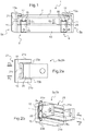
- an electromagnetic actuator 5a, 5b comprises a ferromagnetic structure 21, for example made of soft iron, which carries two magnets 23a, 23b and a coil 25 disposed between the two magnets 23a, 23b.
- the ferromagnetic structure 21 carrying the two magnets 23a, 23b can be carried by the mobile part 11 of the electromagnetic actuator 5a, 5b (see figure 1 ) or alternatively by the fixed part 9 of the electromagnetic actuator 5a, 5b (see figure 3 ).
- the coil 25 can be carried by the fixed part 9 of the electromagnetic actuator 5a, 5b (see figure 1 ) or alternatively by the movable part 11 of the electromagnetic actuator 5a, 5b (see figure 3 ).
- the shape of the plate 3 is adapted to be fixed to the movable part 11 carrying the coil 25. More precisely, the plate 3 has at its ends two extensions which come to be fixed on the movable parts 11.
- the two magnets 23a, 23b are permanent magnets of the same polarity arranged opposite each other so as to generate a first B1 and a second B2 opposite magnetic fields.
- the structure 21 has a general shape substantially E-shaped, with two outer branches 21a, 21b and a central branch 21c.
- an elastic element 15 is provided in each air gap delimited by an outer branch 21a, 21b and the central branch 21c.
- the outer branches 21a, 21b respectively carry a magnet 23a, 23b.
- the magnets 23a, 23b have a substantially flat shape and extend respectively along the outer branches 21a, 21b.
- the central branch 21c engages an opening 27 provided in the body of the coil 25, the central branch 21c thus forming a support for winding the coil 25 which then passes successively through the two opposite magnetic fields B1 and B2.
- This central branch 21c thus also ensures the mechanical guidance of the translation of the movable part 11.
- the winding of the coil 25 is along the longitudinal axis L of the electromagnetic actuator 5a, 5b perpendicular to the magnetic fields B1 and B2 created by the magnets 23a, 23b, so as to generate a translation of the plate 3 in direction D1 or D2 perpendicular both to the longitudinal axis L and to the fields B1, B2.
- the current supply to the coil 25 in a second direction opposite to the first direction and perpendicular to the second magnetic field B2 generated by the magnet 23b, to the lower portion of the coil generates a Laplace force Fl2 perpendicular both to the second magnetic field B2 and to the direction of .
- the two Laplace forces Fl1 and Fl2 generated are oriented in a common drive direction D1 and are combined so that the resulting actuation force drives the movable part 11 in translation in the air gap to move the plate 3 in the direction D1.
- Such an actuator 5a or 5b makes it possible to generate an actuating force alternately in two opposite directions.
- the current supply to the coil 25 of an electromagnetic actuator 5a, 5b makes it possible to move the plate 3 in translation in the direction D2, by reversing the direction of flow of the current.
- the device 1 can also be made for the device 1 to include at least one passive actuator having a general shape substantially similar to the electromagnetic actuator 5a, 5b.
- the term “passive actuator” is understood to mean the fact that this actuator does not include actuation means for driving the movable part 11 in translation in the air gap so as to generate the haptic feedback.
- This passive actuator serves to guide the plate 3 when the haptic feedback is generated by the electromagnetic actuator (s) 5a, 5b.
- the device 1 then no longer requires additional guidance means which may be the source of a hyperstatic problem tending to reduce the overall efficiency of the device 1.
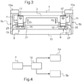
- the device 1 may include a control unit 19 ( figure 4 ) connected to the sensor 7 with a touch surface and to the electromagnetic actuators 5a, 5b to provide an independent control signal to each actuator 1 so as to drive the plate 3 in motion, when a press is detected on the touch surface.
- the control signal can be square or sinusoidal.
- Unit 19 can, for example, supply a periodic supply signal to each electromagnetic actuator 5a, 5b, the supply signals being out of phase.
- the phase shift can be adapted to the position of the support detected.
- the supply signals are phase-shifted by 180 ° so that when the electromagnetic actuator 5a directs the plate 3 in the direction D1, the electromagnetic actuator 5b directs the plate 3 in the direction D2 opposite to the direction D1 (see figures 1 and 3 ).
- Such a control in phase opposition of the two electromagnetic actuators 5a, 5b plays a rocking effect which practically makes it possible to double the acceleration and therefore to amplify the mechanical power to generate the haptic feedback. Moreover, given the short displacement stroke of the movable part 11, the user feels a uniform haptic feedback despite the rocking effect.
- the unit 19 can control the application of different voltage levels to the terminals of each actuator 1.
- the unit 19 can adapt the control signals as a function of the position of the finger on the touch surface.
- the haptic feedback can be generated firstly, for example with a piloting in phase opposition in two opposite directions, then by a simultaneous piloting in a common direction when the finger arrives at the center of the touch surface, and vice versa.
- a control device 1 comprising such an electromagnetic actuator 5a, 5b makes it possible to generate in an improved manner a haptic feedback to a user in a horizontal or vertical plane relative to the plate 3 for supporting the touch surface.
Landscapes
- Engineering & Computer Science (AREA)
- General Engineering & Computer Science (AREA)
- Theoretical Computer Science (AREA)
- Human Computer Interaction (AREA)
- Physics & Mathematics (AREA)
- General Physics & Mathematics (AREA)
- User Interface Of Digital Computer (AREA)
- Reciprocating, Oscillating Or Vibrating Motors (AREA)
- Apparatuses For Generation Of Mechanical Vibrations (AREA)
Applications Claiming Priority (2)
| Application Number | Priority Date | Filing Date | Title |
|---|---|---|---|
| FR0802323A FR2930657B1 (fr) | 2008-04-25 | 2008-04-25 | Dispositif de commande a retour haptique et actionneur electromagnetique correspondant |
| PCT/EP2009/054681 WO2009130188A2 (fr) | 2008-04-25 | 2009-04-20 | Actionneur electromagnetique et dispositif de commande a retour haptique correspondant |
Publications (2)
| Publication Number | Publication Date |
|---|---|
| EP2277095A2 EP2277095A2 (fr) | 2011-01-26 |
| EP2277095B1 true EP2277095B1 (fr) | 2020-09-09 |
Family
ID=40091256
Family Applications (1)
| Application Number | Title | Priority Date | Filing Date |
|---|---|---|---|
| EP09735933.5A Active EP2277095B1 (fr) | 2008-04-25 | 2009-04-20 | Actionneur electromagnetique et dispositif de commande a retour haptique correspondant |
Country Status (5)
| Country | Link |
|---|---|
| US (1) | US8760248B2 (ja) |
| EP (1) | EP2277095B1 (ja) |
| JP (1) | JP6106360B2 (ja) |
| FR (1) | FR2930657B1 (ja) |
| WO (1) | WO2009130188A2 (ja) |
Families Citing this family (39)
| Publication number | Priority date | Publication date | Assignee | Title |
|---|---|---|---|---|
| FR2944614B1 (fr) * | 2009-04-20 | 2011-06-03 | Dav | Dispositif de commande a retour haptique et actionneur correspondant |
| FR2944613B1 (fr) * | 2009-04-20 | 2011-06-03 | Dav | Dispositif de commande a retour haptique |
| DE102010007486A1 (de) * | 2010-02-09 | 2011-08-11 | Continental Automotive GmbH, 30165 | Bedienvorrichtung |
| JP5815698B2 (ja) * | 2010-07-16 | 2015-11-17 | コーニンクレッカ フィリップス エヌ ヴェKoninklijke Philips N.V. | 触覚面上に触覚効果を生じさせる複アクチュエータ触覚面を含む装置 |
| FR2977363B1 (fr) * | 2011-06-30 | 2014-02-28 | Dav | Module d'interface tactile a retour haptique |
| DE102011079357B4 (de) * | 2011-07-18 | 2015-10-15 | Continental Automotive Gmbh | Bedieneinrichtung |
| DE112013003425T5 (de) | 2012-07-07 | 2015-04-09 | Saia-Burgess Llc | Haptische Aktuatoren |
| FR2999740B1 (fr) * | 2012-12-13 | 2018-03-30 | Dav | Actionneur pour module d'interface tactile a retour haptique |
| US9436341B2 (en) | 2012-12-21 | 2016-09-06 | Johnson Electric S.A. | Haptic feedback devices |
| US10282014B2 (en) | 2013-09-30 | 2019-05-07 | Apple Inc. | Operating multiple functions in a display of an electronic device |
| US9726922B1 (en) | 2013-12-20 | 2017-08-08 | Apple Inc. | Reducing display noise in an electronic device |
| US10275028B2 (en) | 2014-09-22 | 2019-04-30 | Samsung Electronics Company, Ltd. | Magnetic haptic system |
| FR3032396B1 (fr) * | 2015-02-10 | 2020-08-28 | Dav | Dispositif de retour haptique pour vehicule automobile |
| US10296123B2 (en) | 2015-03-06 | 2019-05-21 | Apple Inc. | Reducing noise in a force signal in an electronic device |
| US10185397B2 (en) | 2015-03-08 | 2019-01-22 | Apple Inc. | Gap sensor for haptic feedback assembly |
| DE102015107828B4 (de) * | 2015-05-19 | 2018-03-08 | Trw Automotive Electronics & Components Gmbh | Schaltvorrichtung |
| WO2016195588A1 (en) * | 2015-06-03 | 2016-12-08 | Razer (Asia-Pacific) Pte. Ltd. | Haptics devices and methods for controlling a haptics device |
| DE102015008571B4 (de) | 2015-07-02 | 2017-08-24 | Audi Ag | Kraftfahrzeug-Bedienvorrichtung mit verfahrbarer Bedienoberfläche |
| DE102015008537A1 (de) * | 2015-07-02 | 2017-01-05 | Audi Ag | Kraftfahrzeug-Bedienvorrichtung mit haptischer Rückmeldung |
| US9927905B2 (en) | 2015-08-19 | 2018-03-27 | Apple Inc. | Force touch button emulation |
| US10416811B2 (en) | 2015-09-24 | 2019-09-17 | Apple Inc. | Automatic field calibration of force input sensors |
| JP6828029B2 (ja) * | 2015-10-13 | 2021-02-10 | ダヴ | タクト・インターフェースモジュールのアクチュエータ、タクト・インターフェースモジュール、及び触覚フィードバックを生成する方法 |
| FR3042289B1 (fr) * | 2015-10-13 | 2019-08-16 | Dav | Module d'interface tactile et procede de generation d'un retour haptique |
| DE102015120605A1 (de) * | 2015-11-27 | 2017-06-01 | Valeo Schalter Und Sensoren Gmbh | Bedienvorrichtung für ein Kraftfahrzeug mit Antriebseinrichtung zum Ausgeben einer haptischen Rückmeldung sowie Kraftfahrzeug |
| DE102016005926A1 (de) * | 2016-05-14 | 2017-11-16 | Leopold Kostal Gmbh & Co. Kg | Elektromagnetischer Feedback-Aktuator für ein Bedienelement und Anordnung mit mindestens einem elektromagnetischen Feedback-Aktuator |
| WO2017219137A1 (en) * | 2016-06-24 | 2017-12-28 | Nanoport Technology Inc. | Tactile feedback actuator, electronic device using same, and method of operating same |
| WO2018162704A1 (de) * | 2017-03-09 | 2018-09-13 | Behr-Hella Thermocontrol Gmbh | Elektromagnetischer aktuator für eine mechanische rückmeldeeinheit |
| IT201700058490A1 (it) * | 2017-05-30 | 2018-11-30 | Bitron Spa | Plancia di comando con dispositivo di riscontro aptico. |
| DE202018101900U1 (de) * | 2018-04-09 | 2018-04-17 | Preh Gmbh | Berührempfindliches Eingabegerät mit in Maximalmagnetisierung betriebenem, elektromagnetischem Aktuator |
| JP7038601B2 (ja) | 2018-05-28 | 2022-03-18 | 京セラ株式会社 | ユニット及び触感呈示装置 |
| US10345910B1 (en) * | 2018-06-15 | 2019-07-09 | Immersion Corporation | Haptic actuator assembly with a spring pre-load device |
| US11410109B2 (en) * | 2018-11-01 | 2022-08-09 | Precog, LLC | Portable real-time experience communications device and monitoring system |
| US10890974B2 (en) | 2018-11-07 | 2021-01-12 | Microsoft Technology Licensing, Llc | Electromagnetically actuating a haptic feedback system |
| KR20220007858A (ko) * | 2019-05-09 | 2022-01-19 | 베르-헬라 테르모콘트롤 게엠베하 | 자동차용 조작유닛 |
| DE102019112461A1 (de) | 2019-05-13 | 2020-11-19 | Preh Gmbh | Eingabeanordnung mit aktivem haptischem feedback und störschwingungsunterdrückung |
| US11496034B2 (en) | 2019-06-14 | 2022-11-08 | Apple Inc. | Haptic actuator having a double-wound driving coil for temperature-independent velocity sensing |
| US11527946B2 (en) * | 2019-06-14 | 2022-12-13 | Apple Inc. | Haptic actuator having a double-wound driving coil for temperature- and driving current-independent velocity sensing |
| FR3099260B1 (fr) * | 2019-07-23 | 2022-03-04 | Valeo Comfort & Driving Assistance | Procédé de calibration d’un actionneur haptique et actionneur haptique |
| FR3099833A1 (fr) * | 2019-08-07 | 2021-02-12 | Moving Magnet Technologies | Interface haptique passive |
Citations (1)
| Publication number | Priority date | Publication date | Assignee | Title |
|---|---|---|---|---|
| US20050017947A1 (en) * | 2000-01-19 | 2005-01-27 | Shahoian Erik J. | Haptic input devices |
Family Cites Families (9)
| Publication number | Priority date | Publication date | Assignee | Title |
|---|---|---|---|---|
| US5189660A (en) * | 1991-05-09 | 1993-02-23 | Tandy Corporation | Optical data storage system with unitary ferrous frame |
| US5717423A (en) * | 1994-12-30 | 1998-02-10 | Merltec Innovative Research | Three-dimensional display |
| KR19980032013A (ko) * | 1995-12-15 | 1998-07-25 | 모리시타요오이찌 | 진동 발생장치 |
| FR2778267B1 (fr) * | 1998-04-30 | 2000-07-21 | Otis Elevator Co | Bouton d'appel d'ascenseur pour non-voyants |
| US6982696B1 (en) | 1999-07-01 | 2006-01-03 | Immersion Corporation | Moving magnet actuator for providing haptic feedback |
| FR2802302B1 (fr) | 1999-12-09 | 2002-02-15 | Sagem | Appareil de mesure de l'intensite du courant dans un conducteur |
| US6347036B1 (en) * | 2000-03-29 | 2002-02-12 | Dell Products L.P. | Apparatus and method for mounting a heat generating component in a computer system |
| DE10243600A1 (de) * | 2002-09-19 | 2004-04-01 | Delphi Technologies, Inc., Troy | Elektrischer Schalter |
| DE202006011302U1 (de) * | 2006-07-22 | 2006-09-21 | Hoffmann & Krippner Gmbh | Tastatur |
-
2008
- 2008-04-25 FR FR0802323A patent/FR2930657B1/fr active Active
-
2009
- 2009-04-20 EP EP09735933.5A patent/EP2277095B1/fr active Active
- 2009-04-20 US US12/937,769 patent/US8760248B2/en active Active
- 2009-04-20 WO PCT/EP2009/054681 patent/WO2009130188A2/fr active Application Filing
- 2009-04-20 JP JP2011505474A patent/JP6106360B2/ja active Active
Patent Citations (1)
| Publication number | Priority date | Publication date | Assignee | Title |
|---|---|---|---|---|
| US20050017947A1 (en) * | 2000-01-19 | 2005-01-27 | Shahoian Erik J. | Haptic input devices |
Also Published As
| Publication number | Publication date |
|---|---|
| US20110037546A1 (en) | 2011-02-17 |
| JP6106360B2 (ja) | 2017-03-29 |
| US8760248B2 (en) | 2014-06-24 |
| EP2277095A2 (fr) | 2011-01-26 |
| WO2009130188A2 (fr) | 2009-10-29 |
| WO2009130188A3 (fr) | 2010-07-15 |
| FR2930657A1 (fr) | 2009-10-30 |
| FR2930657B1 (fr) | 2010-04-30 |
| JP2012524506A (ja) | 2012-10-11 |
Similar Documents
| Publication | Publication Date | Title |
|---|---|---|
| EP2277095B1 (fr) | Actionneur electromagnetique et dispositif de commande a retour haptique correspondant | |
| EP2630555B2 (fr) | Module d'interface tactile à retour haptique | |
| EP2740016B1 (fr) | Module d'interface tactile | |
| EP2932353B1 (fr) | Actionneur pour module d'interface tactile à retour haptique | |
| EP3221773B1 (fr) | Dispositif de retour haptique pour véhicule automobile | |
| EP3362874B1 (fr) | Actionneur de module d'interface tactile, module d'interface tactile et procédé de génération d'un retour haptique | |
| EP2244168B1 (fr) | Dispositif de commande à retour haptique et actionneur correspondant | |
| EP3362873B1 (fr) | Module d'interface tactile et procédé de génération d'un retour haptique | |
| WO2016051114A1 (fr) | Dispositif de commande pour véhicule automobile | |
| EP2244167B1 (fr) | Dispositif de commande à retour haptique | |
| FR2977334A1 (fr) | Module d'interface tactile a retour haptique | |
| WO2010055234A1 (fr) | Dispositif de commande à retour haptique et actionneur correspondant | |
| WO2010046495A1 (fr) | Dispositif de commande à retour haptique | |
| WO2016128673A1 (fr) | Dispositif de retour haptique pour véhicule automobile | |
| EP2180396B1 (fr) | Dispositif de commande à retour haptique | |
| WO2023002129A1 (fr) | Actionneur oscillant destiné à générer une vibration haptique | |
| FR2977363A1 (fr) | Module d'interface tactile a retour haptique | |
| FR2937785A1 (fr) | Dispositif de commande pour vehicule automobile et actionneur correspondant |
Legal Events
| Date | Code | Title | Description |
|---|---|---|---|
| PUAI | Public reference made under article 153(3) epc to a published international application that has entered the european phase |
Free format text: ORIGINAL CODE: 0009012 |
|
| AK | Designated contracting states |
Kind code of ref document: A2 Designated state(s): AT BE BG CH CY CZ DE DK EE ES FI FR GB GR HR HU IE IS IT LI LT LU LV MC MK MT NL NO PL PT RO SE SI SK TR |
|
| AX | Request for extension of the european patent |
Extension state: AL BA RS |
|
| 17P | Request for examination filed |
Effective date: 20101004 |
|
| DAX | Request for extension of the european patent (deleted) | ||
| 17Q | First examination report despatched |
Effective date: 20120620 |
|
| STAA | Information on the status of an ep patent application or granted ep patent |
Free format text: STATUS: EXAMINATION IS IN PROGRESS |
|
| GRAP | Despatch of communication of intention to grant a patent |
Free format text: ORIGINAL CODE: EPIDOSNIGR1 |
|
| STAA | Information on the status of an ep patent application or granted ep patent |
Free format text: STATUS: GRANT OF PATENT IS INTENDED |
|
| INTG | Intention to grant announced |
Effective date: 20191025 |
|
| GRAJ | Information related to disapproval of communication of intention to grant by the applicant or resumption of examination proceedings by the epo deleted |
Free format text: ORIGINAL CODE: EPIDOSDIGR1 |
|
| STAA | Information on the status of an ep patent application or granted ep patent |
Free format text: STATUS: EXAMINATION IS IN PROGRESS |
|
| INTC | Intention to grant announced (deleted) | ||
| GRAP | Despatch of communication of intention to grant a patent |
Free format text: ORIGINAL CODE: EPIDOSNIGR1 |
|
| STAA | Information on the status of an ep patent application or granted ep patent |
Free format text: STATUS: GRANT OF PATENT IS INTENDED |
|
| INTG | Intention to grant announced |
Effective date: 20200403 |
|
| GRAS | Grant fee paid |
Free format text: ORIGINAL CODE: EPIDOSNIGR3 |
|
| GRAA | (expected) grant |
Free format text: ORIGINAL CODE: 0009210 |
|
| STAA | Information on the status of an ep patent application or granted ep patent |
Free format text: STATUS: THE PATENT HAS BEEN GRANTED |
|
| AK | Designated contracting states |
Kind code of ref document: B1 Designated state(s): AT BE BG CH CY CZ DE DK EE ES FI FR GB GR HR HU IE IS IT LI LT LU LV MC MK MT NL NO PL PT RO SE SI SK TR |
|
| REG | Reference to a national code |
Ref country code: GB Ref legal event code: FG4D Free format text: NOT ENGLISH |
|
| REG | Reference to a national code |
Ref country code: AT Ref legal event code: REF Ref document number: 1312402 Country of ref document: AT Kind code of ref document: T Effective date: 20200915 Ref country code: CH Ref legal event code: EP |
|
| REG | Reference to a national code |
Ref country code: IE Ref legal event code: FG4D Free format text: LANGUAGE OF EP DOCUMENT: FRENCH |
|
| REG | Reference to a national code |
Ref country code: DE Ref legal event code: R096 Ref document number: 602009062741 Country of ref document: DE |
|
| REG | Reference to a national code |
Ref country code: LT Ref legal event code: MG4D |
|
| PG25 | Lapsed in a contracting state [announced via postgrant information from national office to epo] |
Ref country code: FI Free format text: LAPSE BECAUSE OF FAILURE TO SUBMIT A TRANSLATION OF THE DESCRIPTION OR TO PAY THE FEE WITHIN THE PRESCRIBED TIME-LIMIT Effective date: 20200909 Ref country code: SE Free format text: LAPSE BECAUSE OF FAILURE TO SUBMIT A TRANSLATION OF THE DESCRIPTION OR TO PAY THE FEE WITHIN THE PRESCRIBED TIME-LIMIT Effective date: 20200909 Ref country code: HR Free format text: LAPSE BECAUSE OF FAILURE TO SUBMIT A TRANSLATION OF THE DESCRIPTION OR TO PAY THE FEE WITHIN THE PRESCRIBED TIME-LIMIT Effective date: 20200909 Ref country code: LT Free format text: LAPSE BECAUSE OF FAILURE TO SUBMIT A TRANSLATION OF THE DESCRIPTION OR TO PAY THE FEE WITHIN THE PRESCRIBED TIME-LIMIT Effective date: 20200909 Ref country code: GR Free format text: LAPSE BECAUSE OF FAILURE TO SUBMIT A TRANSLATION OF THE DESCRIPTION OR TO PAY THE FEE WITHIN THE PRESCRIBED TIME-LIMIT Effective date: 20201210 Ref country code: BG Free format text: LAPSE BECAUSE OF FAILURE TO SUBMIT A TRANSLATION OF THE DESCRIPTION OR TO PAY THE FEE WITHIN THE PRESCRIBED TIME-LIMIT Effective date: 20201209 Ref country code: NO Free format text: LAPSE BECAUSE OF FAILURE TO SUBMIT A TRANSLATION OF THE DESCRIPTION OR TO PAY THE FEE WITHIN THE PRESCRIBED TIME-LIMIT Effective date: 20201209 |
|
| REG | Reference to a national code |
Ref country code: AT Ref legal event code: MK05 Ref document number: 1312402 Country of ref document: AT Kind code of ref document: T Effective date: 20200909 |
|
| REG | Reference to a national code |
Ref country code: NL Ref legal event code: MP Effective date: 20200909 |
|
| PG25 | Lapsed in a contracting state [announced via postgrant information from national office to epo] |
Ref country code: PL Free format text: LAPSE BECAUSE OF FAILURE TO SUBMIT A TRANSLATION OF THE DESCRIPTION OR TO PAY THE FEE WITHIN THE PRESCRIBED TIME-LIMIT Effective date: 20200909 Ref country code: LV Free format text: LAPSE BECAUSE OF FAILURE TO SUBMIT A TRANSLATION OF THE DESCRIPTION OR TO PAY THE FEE WITHIN THE PRESCRIBED TIME-LIMIT Effective date: 20200909 |
|
| PG25 | Lapsed in a contracting state [announced via postgrant information from national office to epo] |
Ref country code: RO Free format text: LAPSE BECAUSE OF FAILURE TO SUBMIT A TRANSLATION OF THE DESCRIPTION OR TO PAY THE FEE WITHIN THE PRESCRIBED TIME-LIMIT Effective date: 20200909 Ref country code: NL Free format text: LAPSE BECAUSE OF FAILURE TO SUBMIT A TRANSLATION OF THE DESCRIPTION OR TO PAY THE FEE WITHIN THE PRESCRIBED TIME-LIMIT Effective date: 20200909 Ref country code: PT Free format text: LAPSE BECAUSE OF FAILURE TO SUBMIT A TRANSLATION OF THE DESCRIPTION OR TO PAY THE FEE WITHIN THE PRESCRIBED TIME-LIMIT Effective date: 20210111 Ref country code: EE Free format text: LAPSE BECAUSE OF FAILURE TO SUBMIT A TRANSLATION OF THE DESCRIPTION OR TO PAY THE FEE WITHIN THE PRESCRIBED TIME-LIMIT Effective date: 20200909 Ref country code: CZ Free format text: LAPSE BECAUSE OF FAILURE TO SUBMIT A TRANSLATION OF THE DESCRIPTION OR TO PAY THE FEE WITHIN THE PRESCRIBED TIME-LIMIT Effective date: 20200909 |
|
| PG25 | Lapsed in a contracting state [announced via postgrant information from national office to epo] |
Ref country code: IS Free format text: LAPSE BECAUSE OF FAILURE TO SUBMIT A TRANSLATION OF THE DESCRIPTION OR TO PAY THE FEE WITHIN THE PRESCRIBED TIME-LIMIT Effective date: 20210109 Ref country code: ES Free format text: LAPSE BECAUSE OF FAILURE TO SUBMIT A TRANSLATION OF THE DESCRIPTION OR TO PAY THE FEE WITHIN THE PRESCRIBED TIME-LIMIT Effective date: 20200909 Ref country code: AT Free format text: LAPSE BECAUSE OF FAILURE TO SUBMIT A TRANSLATION OF THE DESCRIPTION OR TO PAY THE FEE WITHIN THE PRESCRIBED TIME-LIMIT Effective date: 20200909 |
|
| REG | Reference to a national code |
Ref country code: DE Ref legal event code: R097 Ref document number: 602009062741 Country of ref document: DE |
|
| PG25 | Lapsed in a contracting state [announced via postgrant information from national office to epo] |
Ref country code: SK Free format text: LAPSE BECAUSE OF FAILURE TO SUBMIT A TRANSLATION OF THE DESCRIPTION OR TO PAY THE FEE WITHIN THE PRESCRIBED TIME-LIMIT Effective date: 20200909 |
|
| PLBE | No opposition filed within time limit |
Free format text: ORIGINAL CODE: 0009261 |
|
| STAA | Information on the status of an ep patent application or granted ep patent |
Free format text: STATUS: NO OPPOSITION FILED WITHIN TIME LIMIT |
|
| 26N | No opposition filed |
Effective date: 20210610 |
|
| PG25 | Lapsed in a contracting state [announced via postgrant information from national office to epo] |
Ref country code: SI Free format text: LAPSE BECAUSE OF FAILURE TO SUBMIT A TRANSLATION OF THE DESCRIPTION OR TO PAY THE FEE WITHIN THE PRESCRIBED TIME-LIMIT Effective date: 20200909 Ref country code: DK Free format text: LAPSE BECAUSE OF FAILURE TO SUBMIT A TRANSLATION OF THE DESCRIPTION OR TO PAY THE FEE WITHIN THE PRESCRIBED TIME-LIMIT Effective date: 20200909 |
|
| PG25 | Lapsed in a contracting state [announced via postgrant information from national office to epo] |
Ref country code: IT Free format text: LAPSE BECAUSE OF FAILURE TO SUBMIT A TRANSLATION OF THE DESCRIPTION OR TO PAY THE FEE WITHIN THE PRESCRIBED TIME-LIMIT Effective date: 20200909 |
|
| PG25 | Lapsed in a contracting state [announced via postgrant information from national office to epo] |
Ref country code: MC Free format text: LAPSE BECAUSE OF FAILURE TO SUBMIT A TRANSLATION OF THE DESCRIPTION OR TO PAY THE FEE WITHIN THE PRESCRIBED TIME-LIMIT Effective date: 20200909 |
|
| GBPC | Gb: european patent ceased through non-payment of renewal fee |
Effective date: 20210420 |
|
| PG25 | Lapsed in a contracting state [announced via postgrant information from national office to epo] |
Ref country code: LU Free format text: LAPSE BECAUSE OF NON-PAYMENT OF DUE FEES Effective date: 20210420 |
|
| REG | Reference to a national code |
Ref country code: BE Ref legal event code: MM Effective date: 20210430 |
|
| PG25 | Lapsed in a contracting state [announced via postgrant information from national office to epo] |
Ref country code: CH Free format text: LAPSE BECAUSE OF NON-PAYMENT OF DUE FEES Effective date: 20210430 Ref country code: LI Free format text: LAPSE BECAUSE OF NON-PAYMENT OF DUE FEES Effective date: 20210430 Ref country code: GB Free format text: LAPSE BECAUSE OF NON-PAYMENT OF DUE FEES Effective date: 20210420 |
|
| PG25 | Lapsed in a contracting state [announced via postgrant information from national office to epo] |
Ref country code: IE Free format text: LAPSE BECAUSE OF NON-PAYMENT OF DUE FEES Effective date: 20210420 |
|
| PG25 | Lapsed in a contracting state [announced via postgrant information from national office to epo] |
Ref country code: IS Free format text: LAPSE BECAUSE OF FAILURE TO SUBMIT A TRANSLATION OF THE DESCRIPTION OR TO PAY THE FEE WITHIN THE PRESCRIBED TIME-LIMIT Effective date: 20210109 |
|
| PG25 | Lapsed in a contracting state [announced via postgrant information from national office to epo] |
Ref country code: BE Free format text: LAPSE BECAUSE OF NON-PAYMENT OF DUE FEES Effective date: 20210430 |
|
| PG25 | Lapsed in a contracting state [announced via postgrant information from national office to epo] |
Ref country code: HU Free format text: LAPSE BECAUSE OF FAILURE TO SUBMIT A TRANSLATION OF THE DESCRIPTION OR TO PAY THE FEE WITHIN THE PRESCRIBED TIME-LIMIT; INVALID AB INITIO Effective date: 20090420 Ref country code: CY Free format text: LAPSE BECAUSE OF FAILURE TO SUBMIT A TRANSLATION OF THE DESCRIPTION OR TO PAY THE FEE WITHIN THE PRESCRIBED TIME-LIMIT Effective date: 20200909 |
|
| P01 | Opt-out of the competence of the unified patent court (upc) registered |
Effective date: 20230528 |
|
| PGFP | Annual fee paid to national office [announced via postgrant information from national office to epo] |
Ref country code: FR Payment date: 20230425 Year of fee payment: 15 Ref country code: DE Payment date: 20230412 Year of fee payment: 15 |
|
| PG25 | Lapsed in a contracting state [announced via postgrant information from national office to epo] |
Ref country code: MK Free format text: LAPSE BECAUSE OF FAILURE TO SUBMIT A TRANSLATION OF THE DESCRIPTION OR TO PAY THE FEE WITHIN THE PRESCRIBED TIME-LIMIT Effective date: 20200909 |