EP2276660B1 - Robot for climbing posts - Google Patents
Robot for climbing posts Download PDFInfo
- Publication number
- EP2276660B1 EP2276660B1 EP09726057A EP09726057A EP2276660B1 EP 2276660 B1 EP2276660 B1 EP 2276660B1 EP 09726057 A EP09726057 A EP 09726057A EP 09726057 A EP09726057 A EP 09726057A EP 2276660 B1 EP2276660 B1 EP 2276660B1
- Authority
- EP
- European Patent Office
- Prior art keywords
- post
- support
- robot
- climbing robot
- robot according
- Prior art date
- Legal status (The legal status is an assumption and is not a legal conclusion. Google has not performed a legal analysis and makes no representation as to the accuracy of the status listed.)
- Active
Links
- 230000009194 climbing Effects 0.000 title claims description 23
- 230000005484 gravity Effects 0.000 claims abstract description 15
- 230000033001 locomotion Effects 0.000 claims abstract description 15
- 230000007246 mechanism Effects 0.000 claims description 15
- 230000008878 coupling Effects 0.000 claims description 2
- 238000010168 coupling process Methods 0.000 claims description 2
- 238000005859 coupling reaction Methods 0.000 claims description 2
- 239000000725 suspension Substances 0.000 claims 4
- 238000005096 rolling process Methods 0.000 abstract description 13
- 241001503987 Clematis vitalba Species 0.000 description 14
- 230000005540 biological transmission Effects 0.000 description 8
- 238000005265 energy consumption Methods 0.000 description 6
- 241001644893 Entandrophragma utile Species 0.000 description 5
- 238000006073 displacement reaction Methods 0.000 description 5
- 229910052782 aluminium Inorganic materials 0.000 description 4
- XAGFODPZIPBFFR-UHFFFAOYSA-N aluminium Chemical compound [Al] XAGFODPZIPBFFR-UHFFFAOYSA-N 0.000 description 4
- 239000003638 chemical reducing agent Substances 0.000 description 4
- 238000004891 communication Methods 0.000 description 4
- 230000008901 benefit Effects 0.000 description 3
- 238000011109 contamination Methods 0.000 description 3
- 230000037230 mobility Effects 0.000 description 3
- 230000008447 perception Effects 0.000 description 3
- 230000002787 reinforcement Effects 0.000 description 3
- 230000003068 static effect Effects 0.000 description 3
- 239000004411 aluminium Substances 0.000 description 2
- 230000000295 complement effect Effects 0.000 description 2
- 230000006835 compression Effects 0.000 description 2
- 238000007906 compression Methods 0.000 description 2
- 230000006870 function Effects 0.000 description 2
- 239000007787 solid Substances 0.000 description 2
- 239000000126 substance Substances 0.000 description 2
- 238000006677 Appel reaction Methods 0.000 description 1
- 208000031968 Cadaver Diseases 0.000 description 1
- 241001415961 Gaviidae Species 0.000 description 1
- 241000287107 Passer Species 0.000 description 1
- 241000897276 Termes Species 0.000 description 1
- 230000001133 acceleration Effects 0.000 description 1
- 230000016571 aggressive behavior Effects 0.000 description 1
- 238000013459 approach Methods 0.000 description 1
- 230000001174 ascending effect Effects 0.000 description 1
- 238000013475 authorization Methods 0.000 description 1
- 230000033228 biological regulation Effects 0.000 description 1
- 230000000903 blocking effect Effects 0.000 description 1
- 238000013480 data collection Methods 0.000 description 1
- 230000007423 decrease Effects 0.000 description 1
- 230000003247 decreasing effect Effects 0.000 description 1
- 230000001934 delay Effects 0.000 description 1
- 238000001514 detection method Methods 0.000 description 1
- 230000000694 effects Effects 0.000 description 1
- 238000009434 installation Methods 0.000 description 1
- 230000004807 localization Effects 0.000 description 1
- 230000009347 mechanical transmission Effects 0.000 description 1
- 229910052751 metal Inorganic materials 0.000 description 1
- 239000002184 metal Substances 0.000 description 1
- 238000012544 monitoring process Methods 0.000 description 1
- 238000010422 painting Methods 0.000 description 1
- 244000045947 parasite Species 0.000 description 1
- 230000002093 peripheral effect Effects 0.000 description 1
- 239000003380 propellant Substances 0.000 description 1
- 238000013138 pruning Methods 0.000 description 1
- 230000009257 reactivity Effects 0.000 description 1
- 230000002123 temporal effect Effects 0.000 description 1
- 230000000007 visual effect Effects 0.000 description 1
- XLYOFNOQVPJJNP-UHFFFAOYSA-N water Substances O XLYOFNOQVPJJNP-UHFFFAOYSA-N 0.000 description 1
Images

Classifications
-
- B—PERFORMING OPERATIONS; TRANSPORTING
- B62—LAND VEHICLES FOR TRAVELLING OTHERWISE THAN ON RAILS
- B62D—MOTOR VEHICLES; TRAILERS
- B62D57/00—Vehicles characterised by having other propulsion or other ground- engaging means than wheels or endless track, alone or in addition to wheels or endless track
- B62D57/02—Vehicles characterised by having other propulsion or other ground- engaging means than wheels or endless track, alone or in addition to wheels or endless track with ground-engaging propulsion means, e.g. walking members
- B62D57/024—Vehicles characterised by having other propulsion or other ground- engaging means than wheels or endless track, alone or in addition to wheels or endless track with ground-engaging propulsion means, e.g. walking members specially adapted for moving on inclined or vertical surfaces
-
- A—HUMAN NECESSITIES
- A63—SPORTS; GAMES; AMUSEMENTS
- A63B—APPARATUS FOR PHYSICAL TRAINING, GYMNASTICS, SWIMMING, CLIMBING, OR FENCING; BALL GAMES; TRAINING EQUIPMENT
- A63B27/00—Apparatus for climbing poles, trees, or the like
Definitions
- the invention is in the field of the safety of goods and people, and contributes more particularly to the "crisis management" civil (natural disaster, chemical, biological or radiological contamination, riots) and / or military (actions of peacekeeping, perimeter security, area control, etc. It concerns rather structured environments (urban or rural), but may apply to natural areas.
- the effectiveness of managing such contexts is essentially based on a rapid, reliable and permanent estimate of the situation. This involves gathering all the data needed to characterize it in terms of criticality (what is the level of severity?), Of space (what is the extent of the crisis?) And of time (how is the situation evolving?). In a centralized crisis management, which is the most common case, all of this data must then be forwarded to the central station coordinating actions in the field.
- a first solution is to manually install the sensors considered. But a manual placement of the sensors does not allow to easily benefit from a height positioning.
- the use of ladders, forklifts or any other equivalent means requires significant logistics; the necessary means are not always immediately available and their implementation requires always significant delays, incompatible with the reactivity usually sought in crisis.
- the discretion required for certain uses (police, military) is also penalized when using heavy deployment means.
- Some sites deemed sensitive may be pre-equipped by permanent means to carry out their permanent surveillance.
- This second solution is indeed already adopted for sites such as, for example, public places conducive to aggression or overflowing (surveillance of public transport, crowd control in stadiums) or industrial areas at risk.
- the proposed gripper mechanism is, however, specifically dedicated to this type of medium and consumes energy.
- this system implies a great complexity and requires a large number of sensors to ensure the judicious positioning of the grippers between the nodes of the lattice structure.
- the "climbing robot" presented in the patent US 005542496 is initially intended to climb metal pipes and columns for sanding and / or painting purposes. Taking into account the variation of the diameter of the conical pole to be climbed is carried out with a pneumatic pressing device, heavy, expensive and with high energy consumption. It also calls for a complex pressure regulation loop in order to guarantee the non slip of the robot.
- this device encloses the pole over its entire circumference, which does not seem compatible with the presence of possible obstacles.
- the patent US 2003/0188416 describes a climber robot according to the preamble of claim 1, which comprises a spring-loaded clamping mechanism for holding the robot on the pole.
- Several tree pruning robots exploit the principle of a crown centered on the trunk by several peripheral rollers held pressed against a strong pressure; they are described in the patents US2581479 , US2477922 , US2482392 . All of them require to completely enclose the trunk and include controlled, complex and bulky tightening mechanisms.
- a system capable of climbing along a pole (such as a lamppost, a tree trunk, a gutter, etc.), equipped with means to ensure a mission of surveillance for example, especially in urban areas, and simultaneously satisfying all the aforementioned requirements, ie reduced size and lightness, operating endurance, low energy consumption, easy installation, fast and discreet, autonomy and speed of movement along the post, ability to orientate around the post, ability to cross any tangential obstacles to the post.
- a pole such as a lamppost, a tree trunk, a gutter, etc.
- the climber robot is a robot equipped with displacement means, different sensors, an autonomous energy source and a transceiver for transmitting the information received to a central monitoring station (PC) and to receive from the PC the control commands of the sensors and the means of displacement
- PC central monitoring station
- robot climber we mean a robot able to climb along a pole and down.
- This clamping mechanism comprises for example two adjustable rolling supports, movable relative to the frame and mounted on rotating arms sprung tight. It is possible to add a coupling mechanism making the movements of the two symmetrical arms.
- the support advantageously has a volume able to fit between a plane T tangential to the post and a plane P parallel to T and passing through the axis Oz of the post.
- the motorized displacement means comprise a motor, a propulsion support, an orientable turret and a clutch connected on the one hand to the engine and on the other hand to the propulsion support or to the swiveling turret. .
- the clutch can optionally be replaced by two opposing freewheel mechanisms allowing, depending on the direction of rotation of the engine, to actuate the propulsion of the robot or the orientation of the turret.
- they comprise a propulsion support, a steerable turret, a first engine connected to the propulsion support, and a second engine connected to the steerable turret.
- the invention relates to a climbing robot along a pole.
- pole is meant a vertical structure of frustoconical or cylindrical type. substantially circular or polygonal section, adapted to be gripped by the robot, in part or totally.
- an electric or telephone pole As representative of poles, there may be mentioned an electric or telephone pole, a lamppost, a descent of water, etc.
- the power consumption is greatly reduced compared to the systems of the prior art because only the ascent of the robot is energy consuming.
- the climber robot consumes no more energy, which then becomes fully available for the payload. Maintaining position on the post is ensured without energy consumption by the principle of bracing, that is to say by a wedging obtained during a rubbing contact between the post and the support points of the robot on the pole. The wedging is obtained when the tangential force to the contact tends to increase the normal force, which then increases the tangential force until the blocking.
- bracing that is to say by a wedging obtained during a rubbing contact between the post and
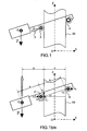
- the robot is braced on two points of support at least as illustrated Figures 1 and 1 bis. It is then stable and can remain attached to the pole 50 without energy consumption.
- the punctual contacts are ensured by rolling supports such as the roller 2 and the ball 4.
- a rolling sub-assembly is called a mechanical subassembly allowing robot support on the pole; it is a rolling solid such as a roller or a ball, in pivot connection or ball joint with another body of the robot, etc. These rolling bearings are motorized to allow the ascent or descent.
- the most relevant choice is to motorize a support, the closest to the body of the robot, that is to say the roller 2. It is also possible to motorize the ball 4 but the transmission mechanism is more complex . The simultaneous motorization of the supports 2 and 4 requires that the two supports advance at the same speed.
- the exploitable vertical structures are frustoconical type elements, with a diameter of between 30 cm and 10 cm. Operation on octagonal structures is possible. It is able to cross strapping around the post and generating a thickness of 5 mm on its surface.
Abstract
Description
L'invention s'inscrit dans le domaine de la sécurité des biens et des personnes, et contribue plus particulièrement à la « gestion de crises » civiles (catastrophe naturelle ; contamination chimique, biologique ou radiologique ; émeutes) et/ou militaires (actions de maintien de la paix, sécurisation de périmètre, contrôle de zone, ...}. Elle concerne plutôt les milieux structurés (urbains ou ruraux), mais s'applique éventuellement aux espaces naturels.
L'efficacité de la gestion de tels contextes repose essentiellement sur une estimation à la fois rapide, fiable et permanente de la situation. Il s'agit pour cela de recueillir l'ensemble des données nécessaires pour la caractériser en termes de criticité (quel est le niveau de gravité ?), d'espace (quelle est l'étendue de la crise ?) et de temps (comment la situation évolue-t-elle ?). Dans une gestion de crise centralisée, qui est le cas le plus courant, l'ensemble de ces données doit ensuite être acheminé au poste central coordonnant les actions sur le terrain.
La nature des données à acquérir pour bâtir et maintenir à jour une bonne représentation de la situation, dépend de la nature de la crise considérée : l'observation visuelle, directe quand elle est possible sans risque ou bien par l'intermédiaire de caméras déportées, constitue clairement une source d'information privilégiée. Les moyens utilisés doivent cependant être compatibles avec le contexte (perception de jour et/ou de nuit, nécessité de points de vue multiples, présence de contamination, discrétion, etc.) et ne suffisent pas forcément à appréhender toutes les dimensions de la crise.
Ainsi, au-delà de la seule vision directe ou déportée, des capteurs dédiés sont souvent requis pour enrichir la connaissance de la situation ; on peut notamment considérer des capteurs acoustiques (microphones), des capteurs de contamination nucléaire, chimique, biologique ou radiologique, des capteurs de température, de détection de mouvements voire des modules de localisation GPS.
Il existe donc un besoin fort d'adaptabilité et de modularité dans les équipements de perception à utiliser, afin de recueillir l'information la plus exhaustive possible.The invention is in the field of the safety of goods and people, and contributes more particularly to the "crisis management" civil (natural disaster, chemical, biological or radiological contamination, riots) and / or military (actions of peacekeeping, perimeter security, area control, etc. It concerns rather structured environments (urban or rural), but may apply to natural areas.
The effectiveness of managing such contexts is essentially based on a rapid, reliable and permanent estimate of the situation. This involves gathering all the data needed to characterize it in terms of criticality (what is the level of severity?), Of space (what is the extent of the crisis?) And of time (how is the situation evolving?). In a centralized crisis management, which is the most common case, all of this data must then be forwarded to the central station coordinating actions in the field.
The nature of the data to be acquired to build and maintain a good representation of the situation, depends on the nature of the crisis considered: the visual observation, direct when it is possible without risk or by means of remote cameras, clearly constitutes a privileged source of information. The means used must, however, be compatible with the context (perception of day and / or night, need for multiple points of view, presence of contamination, discretion, etc.) and are not necessarily sufficient to apprehend all the dimensions of the crisis.
Thus, beyond the mere direct or remote vision, dedicated sensors are often required to enrich the knowledge of the situation; we can especially consider acoustic sensors (microphones), nuclear, chemical, biological or radiological contamination sensors, temperature sensors, motion detection or even GPS location modules.
There is therefore a strong need for adaptability and modularity in the perception equipment to be used, in order to collect the most exhaustive information possible.
La capacité à recueillir simultanément des données sur toute la zone concernée, au travers d'un maillage plus ou moins dense de capteurs complémentaires, constitue un autre facteur de succès de la gestion de crise. Il faut alors disposer des moyens permettant un positionnement adapté et une mise en oeuvre rapide de ces équipements multiples, qui permettront une permanence (endurance) de fonctionnement maximale.
La qualité et la richesse des données délivrées par la majorité des capteurs considérés dépendent fortement de leur placement sur le terrain. Un positionnement en hauteur permet d'étendre la portée de perception, en particulier pour les capteurs d'observation (caméras) qui constituent l'une des sources d'information principales, et permet de s'affranchir des obstacles propres au milieu urbanisé, cadre d'application préférentielle de la présente invention.
Enfin, la collecte d'informations réparties sur la zone de crise doit s'accompagner des moyens de communication adaptés permettant d'acheminer les données vers le poste de gestion centralisée. Les infrastructures existantes (réseaux téléphoniques, réseau internet, ...) peuvent répondre à une partie du besoin, par exemple entre un « noeud de communication du réseau de capteurs » et le poste de gestion centralisée ; par contre, il reste nécessaire de mettre en place les transmissions individuelles (radio) entre les capteurs et ce « noeud de communication », en cherchant à s'affranchir au mieux des difficultés de transmission radio propres au milieu urbain (occultations et masquages, réflexions parasites, ...). Une capacité de positionnement rapide d'antennes et/ou de relais de communication sur des points hauts du milieu urbain est nécessaire à la crédibilité d'un dispositif de recueil d'informations réparti, avec mise en oeuvre accélérée. Cette capacité peut être combinée à celle permettant déjà un déploiement en hauteur des différents capteurs.The ability to simultaneously collect data on the entire area concerned, through a more or less dense network of complementary sensors, is another success factor for crisis management. It is then necessary to have means allowing a suitable positioning and rapid implementation of these multiple equipment, which will allow a permanence (endurance) of maximum operation.
The quality and richness of the data delivered by the majority of the sensors considered depend strongly on their placement in the field. Positioning at a height allows to extend the range of perception, especially for the observation sensors (cameras) which constitute one of the main sources of information, and makes it possible to overcome the obstacles specific to the urbanized environment. preferential application of the present invention.
Finally, the collection of information spread over the crisis zone must be accompanied by appropriate means of communication to route the data to the centralized management position. Existing infrastructures (telephone networks, internet network, etc.) can meet part of the need, for example between a "sensor network communication node" and the centralized management station; on the other hand, it remains necessary to set up the individual transmissions (radio) between the sensors and this "communication node", seeking to overcome at best the radio transmission difficulties specific to the urban environment (occultations and masks, reflections parasites, ...). Rapid antenna positioning and / or communication relay capability at high points in the urban environment is necessary for the credibility of a distributed information collection device, with accelerated implementation. This capacity can be combined with that already allowing a deployment at height of the various sensors.
Une première solution consiste à installer manuellement les capteurs considérés. Mais une mise en place manuelle des capteurs ne permet pas de bénéficier facilement d'un positionnement en hauteur. L'usage d'échelles, de chariots élévateurs ou de tout autre moyen équivalent nécessite une logistique importante ; les moyens nécessaires ne sont pas toujours immédiatement disponibles et leur mise en oeuvre nécessite toujours des délais importants, incompatibles avec la réactivité habituellement recherchée en situation de crise. De plus, la discrétion requise par certaines utilisations (policière, militaire) est également pénalisée lorsque l'on fait appel à des moyens de déploiement lourds.
Certains sites jugés sensibles peuvent être pré-équipés par des moyens à demeure permettant de réaliser leur surveillance permanente. Cette deuxième solution est effectivement d'ores et déjà retenue pour des sites tels que par exemple, des lieux publics propices aux agressions ou aux débordements (surveillance des transports en commun, contrôle de foule dans les stades) ou bien des zones industrielles à risques. Il n'est cependant pas envisageable d'équiper l'ensemble des sites potentiellement concernés par une situation de crise, à la fois pour des raisons économiques et du fait du caractère par définition imprévisible de la crise (par exemple, surveillance de certaines cités sensibles par les forces de police).
Il existe actuellement différents dispositifs électromécaniques capables de se déplacer sur des supports verticaux à 1 degré de liberté (de type échelle ou poteau) ou 2 degrés de liberté (de type paroi).
On connaît des robots capables de se déplacer le long d'un mur au moyen de ventouses (tel que décrit dans le brevet
Le brevet
Le « robot grimpeur » présenté dans le brevet
Le brevet
Plusieurs robots d'élagage d'arbres exploitent le principe d'une couronne centrée sur le tronc par plusieurs galets périphériques maintenus plaqués par une forte pression ; ils sont décrits dans les brevets
Il existe aussi des dispositifs exploitant un mécanisme d'arc-boutement statique permettant de fixer une plate-forme en porte-à-faux sur un poteau ou dans un arbre ; un exemple est présenté dans le brevet
En conséquence, il demeure à ce jour un besoin pour un système capable de grimper le long d'un poteau (tel qu'un lampadaire, un tronc d'arbre, une gouttière, etc.), équipé de moyens pour assurer une mission de surveillance par exemple, notamment en milieu urbain, et donnant simultanément satisfaction à l'ensemble des exigences précitées, à savoir encombrement réduit et légèreté, endurance de fonctionnement, faible consommation d'énergie, installation facile, rapide et discrète, autonomie et rapidité de déplacement le long du poteau, capacité d'orientation autour du poteau, aptitude à franchir d'éventuels obstacles tangentiels au poteau.A first solution is to manually install the sensors considered. But a manual placement of the sensors does not allow to easily benefit from a height positioning. The use of ladders, forklifts or any other equivalent means requires significant logistics; the necessary means are not always immediately available and their implementation requires always significant delays, incompatible with the reactivity usually sought in crisis. In addition, the discretion required for certain uses (police, military) is also penalized when using heavy deployment means.
Some sites deemed sensitive may be pre-equipped by permanent means to carry out their permanent surveillance. This second solution is indeed already adopted for sites such as, for example, public places conducive to aggression or overflowing (surveillance of public transport, crowd control in stadiums) or industrial areas at risk. However, it is not conceivable to equip all sites potentially affected by a crisis situation, both for economic reasons and because of the unpredictable nature of the crisis (for example, surveillance of certain sensitive cities). by the police).
There are currently various electromechanical devices capable of moving on vertical supports with 1 degree of freedom (ladder or column type) or 2 degrees of freedom (wall type).
There are known robots capable of moving along a wall by means of suction cups (as described in the patent
The patent
The "climbing robot" presented in the patent
The patent
Several tree pruning robots exploit the principle of a crown centered on the trunk by several peripheral rollers held pressed against a strong pressure; they are described in the patents
There are also devices using a static bracing mechanism for attaching a platform cantilever on a pole or in a tree; an example is presented in the patent
As a result, there remains to this day a need for a system capable of climbing along a pole (such as a lamppost, a tree trunk, a gutter, etc.), equipped with means to ensure a mission of surveillance for example, especially in urban areas, and simultaneously satisfying all the aforementioned requirements, ie reduced size and lightness, operating endurance, low energy consumption, easy installation, fast and discreet, autonomy and speed of movement along the post, ability to orientate around the post, ability to cross any tangential obstacles to the post.
Le robot grimpeur selon l'invention est un robot équipé de moyens de déplacement, de différents capteurs, d'une source d'énergie autonome et d'un émetteur récepteur pour transmettre les informations captées à un poste central (PC) de surveillance et pour recevoir du PC les consignes de commande des capteurs et des moyens de déplacement
Par robot grimpeur, on entend un robot capable de grimper le long d'un poteau et d'en redescendre.The climber robot according to the invention is a robot equipped with displacement means, different sensors, an autonomous energy source and a transceiver for transmitting the information received to a central monitoring station (PC) and to receive from the PC the control commands of the sensors and the means of displacement
By robot climber, we mean a robot able to climb along a pole and down.
La consommation d'énergie est fortement réduite par rapport aux systèmes de l'art antérieur car le maintien en position sur le poteau est assuré sans consommation d'énergie par le principe d'arc-boutement. Seule l'ascension (ou la descente) du robot est consommatrice d'énergie.
Plus précisément l'invention a pour objet un robot grimpeur mobile le long d'un poteau présentant un axe vertical Oz, qui comprend un bâti équipé de moyens motorisés de déplacement le long du poteau et d'un module de contrôle-commande de ces moyens de déplacement. Il est caractérisé en ce que les moyens motorisés de déplacement comportent des moyens d'arc-boutement dont le centre de gravité G est éloigné de l'axe Oz du poteau, et qui comprennent au moins deux appuis roulants destinés à être en contact avec le poteau, dont au moins un appui roulant motorisé désigné appui propulseur frottant avec le poteau, l'éloignement de G, le coefficient de frottement de l'appui propulseur et l'inclinaison du robot par rapport à l'axe Oz étant liés entre eux de manière à assurer le maintien du robot en position fixe sans consommation d'énergie.
On obtient ainsi un dispositif électro-mécanique permettant d'améliorer l'efficacité de la gestion des crises en milieu structuré. Il a comme avantages :
- une capacité d'emport de charges utiles modulaires et facilement interchangeables, de natures diverses (caméras, capteurs NRBC acronyme de l'expression Nucléaire Radiologique Biologique Chimique, moyens de transmission et relayage radio, antennes, modules de localisation GPS),
- une capacité à positionner rapidement les charges utiles emportées, sur différents supports verticaux du milieu urbain afin d'étendre leurs performances via une exploitation des « positions surélevées »,
- une masse et un gabarit réduits pour un déploiement rapide par un utilisateur unique, sans logistique additionnelle et sans préparation lourde (y compris en termes de déclarations ou d'autorisations),
- une couverture spatiale étendue et simultanée du recueil de données (par exploitation de plusieurs robots grimpeurs, pouvant être équipés de capteurs complémentaires),
- une permanence temporelle du recueil de données : une fois positionné, le robot grimpeur ne consomme plus d'énergie qui devient alors entièrement disponible pour la charge utile ; le positionnement sur des « points hauts extérieurs » associé à la faible consommation des capteurs considérés, permet d'envisager des capteurs solaires pour alimenter l'unité centrale, sur une durée indéfinie.
De préférence, pour des raisons de simplicité de la transmission mécanique, l' (ou les) appui(s) roulant(s) motorisé(s) est (sont) l' (les) appui(s) roulant(s) le(s) plus proche(s) du centre de gravité G.
Afin d'éviter tout déséquilibre des forces de contact du poteau sur le robot, les appuis roulants sont par exemple situés dans un plan GOz, plan de symétrie du robot (avec G = centre de gravité du robot et Oz = axe du poteau) et/ou symétriquement répartis par rapport à ce plan de symétrie.
Le robot s'agrippe au poteau en utilisant le phénomène d'arc-boutement, qui est étroitement lié à la position relative du centre de gravité G de l'ensemble {robot + charge utile} par rapport aux points d'appuis et dépend bien sûr également du coefficient de frottement des contacts aux appuis et de l'inclinaison du robot par rapport à l'axe Oz. Le phénomène d'arc-boutement qui sera rappelé plus loin survient quand G est suffisamment éloigné de l'axe Oz du poteau.
Selon un mode de réalisation de l'invention, le centre de gravité est situé au niveau d'un ensemble moteur-batteries inclus dans les moyens motorisés ; il peut aussi être situé au niveau de la charge utile du robot.
Les moyens d'arc-boutement comportent avantageusement une tourelle orientable selon un axe sensiblement normal au poteau, sur laquelle est monté un appui propulseur. En changeant l'orientation de la tourelle, il devient possible d'avoir un mouvement d'ascension hélicoïdal, voire d'orienter le robot autour du poteau à altitude constante.
Ils comportent également de préférence, au moins un appui roulant non motorisé aussi désigné appui passif et cet (ces) appui(s) passif(s) est(sont) une (des) liaison(s).
Selon une caractéristique de l'invention, afin de permettre l'ascension de poteaux coniques, les moyens d'arc-boutement comportent pour au moins un appui, un mécanisme de serrage destiné à maintenir tous les appuis serrés sur le poteau.The power consumption is greatly reduced compared to the systems of the prior art because the position in position on the pole is ensured without energy consumption by the principle of buttressing. Only the ascent (or descent) of the robot is energy consuming.
More specifically, the invention relates to a mobile climbing robot along a pole having a vertical axis Oz, which comprises a frame equipped with motorized means of movement along the pole and a control-command module of these means. of displacement. It is characterized in that the motorized displacement means comprise bracing means whose center of gravity G is distant from the axis Oz of the pole, and which comprise at least two rolling supports intended to be in contact with the pole, of which at least one motorized rolling support designated support propellant rubbing with the post, the distance of G, the coefficient of friction of the propulsion support and the inclination of the robot relative to the axis Oz being linked together to maintain the robot in a fixed position without energy consumption.
An electro-mechanical device is thus obtained that makes it possible to improve the efficiency of crisis management in a structured medium. It has the following advantages:
- a modular and easily interchangeable payload carrying capacity of various natures (cameras, NRBC sensors, acronym for the expression Nuclear Biological Radiological Radiology, means of transmission and radio relaying, antennas, GPS positioning modules),
- an ability to quickly position the carried payloads, on different vertical supports of the urban environment in order to extend their performances via an exploitation of the "raised positions",
- a reduced mass and size for fast deployment by a single user, without additional logistics and without heavy preparation (including in terms of declarations or authorizations),
- an extensive and simultaneous spatial coverage of data collection (by exploiting several climbing robots, which can be equipped with complementary sensors),
- a temporal permanence of the collection of data: once positioned, the climber robot consumes no more energy which then becomes fully available for the payload; positioning on 'points external high "associated with the low consumption of the sensors considered, allows to consider solar panels to power the CPU, for an indefinite period.
Preferably, for the sake of simplicity of the mechanical transmission, the (or) support (s) motorized (s) is (are) the (s) support (s) rolling (s) the (s) s) nearest to the center of gravity G.
In order to avoid any imbalance of the contact forces of the post on the robot, the rolling supports are for example located in a plane GOz, plane of symmetry of the robot (with G = center of gravity of the robot and Oz = axis of the post) and or symmetrically distributed with respect to this plane of symmetry.
The robot clings to the post using the bracing phenomenon, which is closely related to the relative position of the center of gravity G of the set (robot + payload) relative to the support points and depends on sure also the coefficient of friction of the contacts at the supports and the inclination of the robot with respect to the axis Oz. The bracing phenomenon that will be recalled later occurs when G is sufficiently far from the Oz axis of the pole.
According to one embodiment of the invention, the center of gravity is located at a motor-battery assembly included in the motorized means; it can also be located at the payload of the robot.
The bracing means advantageously comprise an orientable turret along an axis substantially normal to the pole, on which is mounted a propulsion support. By changing the orientation of the turret, it becomes possible to have a helical ascending motion, or even to orient the robot around the pole at constant altitude.
They also preferably include at least one non-motorized rolling support also designated passive support and this (these) support (s) passive (s) is (are) binding (s).
According to a characteristic of the invention, in order to allow the ascent of conical posts, the bracing means comprise for at least one support, a clamping mechanism intended to maintain all the supports tight on the post.
Ce mécanisme de serrage comprend par exemple deux appuis roulants réglables, mobiles par rapport au bâti et montés sur des bras rotatifs serrés par ressorts. Il est possible de rajouter un mécanisme de couplage rendant les déplacements des deux bras symétriques.
L'appui présente avantageusement un volume apte à s'inscrire entre un plan T tangentiel au poteau et un plan P parallèle à T et passant par l'axe Oz du poteau.
Selon une autre caractéristique de l'invention, les moyens motorisés de déplacement comportent un moteur, un appui propulseur, une tourelle orientable et un crabot relié d'une part au moteur et d'autre part à l'appui propulseur ou à la tourelle orientable. Cette disposition permet d'actionner soit la propulsion du robot, soit l'orientation de la tourelle avec un seul moteur et peut contribuer à alléger le robot. Le crabot peut éventuellement être remplacé par deux mécanismes à roues-libres antagonistes permettant, suivant le sens de rotation du moteur, d'actionner la propulsion du robot ou l'orientation de la tourelle.
Selon une variante de réalisation, ils comportent un appui propulseur, une tourelle orientable, un premier moteur relié à l'appui propulseur, et un deuxième moteur relié à la tourelle orientable. L'utilisation de deux moteurs permet plus de fiabilité et des manoeuvres supplémentaires.This clamping mechanism comprises for example two adjustable rolling supports, movable relative to the frame and mounted on rotating arms sprung tight. It is possible to add a coupling mechanism making the movements of the two symmetrical arms.
The support advantageously has a volume able to fit between a plane T tangential to the post and a plane P parallel to T and passing through the axis Oz of the post.
According to another characteristic of the invention, the motorized displacement means comprise a motor, a propulsion support, an orientable turret and a clutch connected on the one hand to the engine and on the other hand to the propulsion support or to the swiveling turret. . This arrangement makes it possible to actuate either the propulsion of the robot or the orientation of the turret with a single motor and can help lighten the robot. The clutch can optionally be replaced by two opposing freewheel mechanisms allowing, depending on the direction of rotation of the engine, to actuate the propulsion of the robot or the orientation of the turret.
According to an alternative embodiment, they comprise a propulsion support, a steerable turret, a first engine connected to the propulsion support, and a second engine connected to the steerable turret. The use of two motors allows more reliability and additional maneuvers.
D'autres caractéristiques et avantages de l'invention apparaîtront à la lecture de la description détaillée qui suit, faite à titre d'exemple non limitatif et en référence aux dessins annexés dans lesquels :
- la
Figure 1 représente schématiquement un exemple de robot grimpeur à deux appuis selon l'invention, en vue de côté, lafigure 1 bis reprenant lafigure 1 pour illustrer le phénomène d'arc-boutement, - les
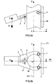
Figures 2 représentent schématiquement un exemple de robot grimpeur à trois appuis selon l'invention, en vue de côté (Fig. 2a ) et de dessus (Fig. 2b ), - la
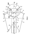
Figure 3 représente la schématisation géométrique d'un robot grimpeur à trois appuis selon l'invention, avec ses cotes caractéristiques pour un diamètre de poteau variable entre Dmin et Dmax, en vue de dessus, - les
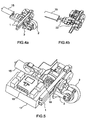
Figures 4 représentent la vue du bloc-transmission dans sa variante à 2 roues libres en perspective, en entier (fig 4a ) et en coupe (fig 4b ), - la
Figure 5 représente la vue du bloc-transmission dans sa variante à crabot en perspective, - les
Figures 6 représentent schématiquement un exemple de robot grimpeur selon l'invention à trois appuis, vue de dessus (fig 6a ) et vue en perspective (fig 6b ).
- the
Figure 1 schematically represents an example of a climber robot with two supports according to the invention, in side view, thefigure 1 bis taking over thefigure 1 to illustrate the phenomenon of arching, - the
Figures 2 schematically represent an example of a robot climber with three supports according to the invention, in side view (Fig. 2a ) and from above (Fig. 2b ) - the
Figure 3 represents the geometrical schematization of a three-armed climber robot according to the invention, with its characteristic dimensions for a variable post diameter between Dmin and Dmax, seen from above, - the
Figures 4 represent the view of the block-transmission in its variant with 2 free wheels in perspective, in full (fig 4a ) and in section (fig 4b ) - the
Figure 5 represents the view of the transmission block in its perspective dog variant, - the
Figures 6 schematically represent an example of a climber robot according to the invention with three supports, viewed from above (fig 6a ) and perspective view (fig 6b ).
L'invention concerne un robot grimpeur le long d'un poteau. Par poteau, on entend une structure verticale de type tronconique ou cylindrique. à section sensiblement circulaire ou polygonale, apte à être enserrée par le robot, en partie ou totalement. A titre représentatif de poteaux, on peut citer un poteau électrique ou téléphonique, un lampadaire, une descente d'eau, etc.
La consommation d'énergie est fortement réduite par rapport aux systèmes de l'art antérieur car seule l'ascension du robot est consommatrice d'énergie. Une fois positionné, le robot grimpeur ne consomme plus d'énergie, qui devient alors entièrement disponible pour la charge utile.
Le maintien en position sur le poteau est assuré sans consommation d'énergie par le principe d'arc-boutement, c'est-à-dire par un coincement obtenu lors d'un contact frottant entre le poteau et les points d'appui du robot sur le poteau. Le coincement s'obtient lorsque la force tangentielle au contact tend à augmenter la force normale, ce qui augmente alors la force tangentielle jusqu'au blocage.
La description est faite en relation avec les figures et la nomenclature suivante.The invention relates to a climbing robot along a pole. By pole is meant a vertical structure of frustoconical or cylindrical type. substantially circular or polygonal section, adapted to be gripped by the robot, in part or totally. As representative of poles, there may be mentioned an electric or telephone pole, a lamppost, a descent of water, etc.
The power consumption is greatly reduced compared to the systems of the prior art because only the ascent of the robot is energy consuming. Once positioned, the climber robot consumes no more energy, which then becomes fully available for the payload.
Maintaining position on the post is ensured without energy consumption by the principle of bracing, that is to say by a wedging obtained during a rubbing contact between the post and the support points of the robot on the pole. The wedging is obtained when the tangential force to the contact tends to increase the normal force, which then increases the tangential force until the blocking.
The description is made in relation to the figures and the following nomenclature.
- 1 Bâti1 Frame
- 2 Appui motorisé : galet propulseur2 Motorized support: thruster
- 3 Tourelle orientable3 swivel turret
- 4 Appui passif à rotule4 passive ball support
- 5 Bras mobile5 Moving arm
- 6 Pivot du bras6 Arm pivot
- 7 Levier arrière du bras7 Rear arm lever
- 8 Renfort de bras mobile8 Mobile arm reinforcement
- 9 Trou de goupille pour réglage de l'ouverture des bras9 Pin hole for adjusting the opening of the arms
- 10 Bielle de commande10 Control rod
- 11 Chariot coulissant11 Sliding trolley
- 12 Tube de guidage de chariot12 Trolley guide tube
- 13 Support avant mobile13 Mobile Front Support
- 14 Support arrière fixe14 Fixed rear support
- 15 Moteur électrique15 Electric motor
- 16 Automate programmable commandable à distance (Bluetooth)16 Remote Controllable Programmable Controller (Bluetooth)
- 17 Bloc de commande (carte de puissance, batteries, ...)17 Control block (power board, batteries, ...)
- 18 Crabot18 Crabot
- 19 Réducteur à engrenages pour la propulsion du galet19 Gear reducer for roller propulsion
- 20 Réducteur à engrenages pour l'orientation de la tourelle20 Gear reducer for turret orientation
- 21 Couronne dentée21 Toothed crown
- 22 Roues libres22 Free wheels
- 50 Poteau cylindrique ou conique50 Cylindrical or conical post
Pour assurer son maintien en position sous l'effet du poids P, le robot est arc-bouté sur deux points d'appuis au minimum comme illustré
Afin de permettre l'ascension ou la descente du robot tout en gardant une cinématique très simple, les contacts ponctuels sont assurés par des appuis roulants tels que le galet 2 et la rotule 4. On appelle appui roulant un sous-ensemble mécanique permettant l'appui du robot sur le poteau ; il s'agit d'un solide roulant tel qu'un galet ou une bille, en liaison pivot ou rotule avec un autre corps du robot, etc.
Ces appuis roulants sont motorisés afin de permettre l'ascension ou la descente. Le choix le plus pertinent consiste à ne motoriser qu'un appui, le plus proche du corps du robot, c'est-à-dire le galet 2. Il est également possible de motoriser la rotule 4 mais le mécanisme de transmission est plus complexe. La motorisation simultanée des appuis 2 et 4 réclame que les deux appuis avancent à la même vitesse.To keep it in position under the effect of the weight P, the robot is braced on two points of support at least as illustrated
In order to allow the ascent or descent of the robot while keeping a very simple kinematics, the punctual contacts are ensured by rolling supports such as the
These rolling bearings are motorized to allow the ascent or descent. The most relevant choice is to motorize a support, the closest to the body of the robot, that is to say the
On rappelle les notions d'arc-boutement.
On dit qu'il y a arc-boutement sur un solide lorsque le phénomène d'adhérence provoque une impossibilité de mouvement quelle que soit l'intensité des actions mécaniques extérieures.
Le robot selon l'invention est basé sur l'arc-boutement pour son maintien en position. Afin d'assurer la mobilité en ascension, les points de contact C1 et C2 sont assurés par les appuis roulants 2 et 4. La
Seul le galet 2 est motorisé. Le contact C1 peut donc transmettre à la fois un effort normal N1 et un effort tangentiel T1. Le galet 4 est libre. Le contact C2 ne transmet qu'un effort normal N2. Il n'y a aucun effort tangentiel.
Ecrivons la condition de maintien en équilibre statique à l'aide du principe fondamental de la statique :
- Bilan des forces selon x :

- Bilan des forces selon z :

- Bilan des moments selon y (direction perpendiculaire au plan de la figure) ramenés au point C1 :

a étant la distance entre le contact C1 du galet 2 et le centre de gravité G, b la distance entre les deux contacts C1 et C2 des galets 2et 4, m la masse du robot, g l'accélération de la pesanteur. - En introduisant le coefficient de frottement µ, la condition de non-glissement en C1 s'écrit :
(éq 2) et (éq 4) permettent de ré-écrire la condition de non glissement :
(éq 1) et (éq 3) permettent d'obtenir l'expression de N1 :
(éq 5) et (éq 6) permettent enfin d'obtenir la condition de non-glissement, garante de l'arc-boutement c'est-à-dire permettant que le robot soit maintenu sur le poteau sans glisser quelle que soit l'intensité des forces extérieures verticales:
d étant le diamètre du poteau, D la distance du centre de gravité G au poteau.
It is said that there is buttressing on a solid when the phenomenon of adhesion causes an impossibility of movement irrespective of the intensity of the external mechanical actions.
The robot according to the invention is based on the bracing for holding it in position. In order to ensure mobility in ascension, the contact points C1 and C2 are provided by the rolling supports 2 and 4. The
Only
Let's write the condition of maintaining static equilibrium using the fundamental principle of statics:
- Balance of forces according to x:
- Balance of forces according to z:
- Balance of moments according to y (direction perpendicular to the plane of the figure) brought back to point C1:
a being the distance between the contact C1 of theroller 2 and the center of gravity G, b the distance between the two contacts C1 and C2 of therollers - By introducing the coefficient of friction μ, the condition of non-slip in C1 is written:
(éq 2) and (éq 4) make it possible to re-write the non slip condition:
(éq 1) and (éq 3) make it possible to obtain the expression of N1:
(eq 5) and (eq 6) finally allow to obtain the non-slip condition, guaranteeing the bracing that is to say that allows the robot to be maintained on the pole without sliding whatever the intensity of the vertical external forces:
d being the diameter of the post, D the distance from the center of gravity G to the post.
On voit que cette condition impose d'avoir un porte-à-faux a suffisamment long pour que l'arc-boutement survienne. Plus l'adhérence augmente (pour de grandes valeurs de µ) et plus a peut être court. Selon (éq 7), moins le robot est incliné (pour de petites valeurs de α) et plus a décroit. En effet, (éq 3) montre que les efforts normaux augmentent lorsque α diminue. Dans le cas d'un robot quasi horizontal, les efforts normaux tendent vers l'infini.
La condition d'arc-boutement (éq 7) dépend uniquement de la géométrie et du coefficient de frottement.We see that this condition requires having a cantilever long enough for the jamming to occur. More adhesion increases (for large values of μ) and more can be short. According to (eq 7), the less the robot is inclined (for small values of α) and more has decreased. Indeed, (eq 3) shows that the normal forces increase when α decreases. In the case of a quasi-horizontal robot, the normal forces tend towards infinity.
The bracing condition (eq 7) depends solely on the geometry and the coefficient of friction.
Pour donner au robot une seconde mobilité en rotation autour du poteau, on monte le galet 2 sur une tourelle orientable 3. Cette tourelle 3 est orientable selon un axe sensiblement normal au poteau 50. De plus, on choisit pour l'appui 4 une liaison compatible simultanément avec les mobilités en ascension et en rotation axiale autour de Oz, une liaison sphérique par exemple.
Afin d'améliorer la stabilité du robot sur le poteau 50 et d'éviter un déversement latéral en rotation autour de l'axe Gx, les points de contact du robot sur le poteau doivent être positionnés symétriquement par rapport au plan GOz, G étant le centre de gravité du robot, Oz l'axe du poteau. Ce plan de symétrie du robot est noté S par la suite. Lorsque seul l'appui le plus proche de G est motorisé, on peut envisager différents cas en se plaçant dans la vue de la
- 2 appuis à 180°
- 3 appuis à 120° (
Figure 2 ) - 4 appuis à 90°
- n appuis à 360°/n, (n>1)
Afin de rendre le robot compatible avec des poteaux coniques, on le dote de deux
Le bâti 1 comporte les segments MLOKN ainsi que le support OT pour les ressorts. On donne dans les tableaux suivants des exemples de dimensions de ces segments ainsi que des exemples de plages de diamètres de poteaux.

Comme aucun ressort ne peut s'allonger suffisamment tout en appliquant les efforts intenses nécessaires en P et R, on propose trois réglages des
Le châssis est par exemple réalisé en tube aluminium soudé très rigide.
On aborde à présent l'aspect motorisation du robot.
Sur les
Selon une variante représentée
Une seconde variante est envisagée qui permet d'améliorer le rendement et la simplicité mécanique. La motorisation est alors assurée par deux moteurs séparés : un gros moteur pour la rotation du galet 2, un moteur plus réduit pour l'orientation de la tourelle 3.
Le centre de gravité G peut être situé dans l'ensemble moteur-batteries ou dans la charge utile.
On va décrire un exemple de robot grimpeur assemblé, en relation avec les
Le robot assemblé intègre le châssis, le bloc-transmission et un module de commande 17.
Les
Chaque
Selon une variante de réalisation, on peut remplacer les ressorts de traction par des ressorts de compression fixés d'une part
L'arrière du bâti 1 supporte un moteur électrique 15 qui est actionné par le biais d'un automate programmable 16 et d'un bloc de commande 17 comportant une carte de puissance et des batteries. Le moteur et les batteries sont des composants pesants positionnés intentionnellement loin de l'axe Oz du poteau afin d'écarter le centre de gravité G et garantir ainsi la bonne fixation du robot par arc-boutement. Le moteur actionne par l'intermédiaire d'un système de crabotage 18, soit un réducteur à engrenage 19 qui entraîne le galet propulseur 2, soit un second réducteur à engrenages 20 qui entraîne la couronne dentée 21 solidaire de la tourelle orientable 3. Les fonctions de propulsion et d'orientation du galet sont donc obtenues avec un seul moteur et un crabot. On peut aussi imaginer de supprimer le crabot 18 et de rajouter un second moteur dévolu exclusivement à l'orientation du galet 2 comme indiqué précédemment.
Un tel robot grimpeur a été réalisé. Il a les principales caractéristiques suivantes.
La masse totale est inférieure à 8 kg et les dimensions repliées restent dans le gabarit suivant : 50 cm x 50 cm x 50 cm.
Il permet l'emport d'une charge utile de 1 kilogramme, dans un espace d'emport dédié constitué d'un cube de 10 cm x 10 cm x 10 cm.
La vitesse maximale en montée et descente est d'au moins 50 m m/s.To give the robot a second rotational mobility around the post, the
In order to improve the stability of the robot on the
- 2 supports at 180 °
- 3 supports at 120 ° (
Figure 2 ) - 4 supports at 90 °
- n supports 360 ° / n, (n> 1)
In order to make the robot compatible with conical posts, it is provided with two
The
The
Since no spring can lengthen sufficiently while applying the intense forces required in P and R, three adjustments of the arms of the robot allowing climbing of poles within the diameter ranges indicated in the table above are proposed. To go from one configuration to another, we modify the triangulation of the arms, that is to say the angle α between SM and MR, respectively VN and NP, by means of
The frame is for example made of very rigid welded aluminum tube.
We now approach the motorization aspect of the robot.
On the
According to a variant represented
A second variant is envisaged which improves the efficiency and mechanical simplicity. The motorization is then ensured by two separate motors: a large motor for the rotation of the
The center of gravity G may be located in the engine-battery unit or in the payload.
We will describe an example of assembled climber robot, in relation with the
The assembled robot integrates the chassis, the transmission block and a
The
Each
The
According to an alternative embodiment, the tension springs can be replaced by compression springs fixed on the one hand to the sliding
The rear of the
Such a climber robot has been realized. It has the following main features.
The total mass is less than 8 kg and the folded dimensions remain in the following template: 50 cm x 50 cm x 50 cm.
It allows the carrying of a payload of 1 kilogram, in a dedicated carrying space consisting of a cube of 10 cm x 10 cm x 10 cm.
The maximum speed in ascent and descent is at least 50 mm / s.
Les structures verticales exploitables sont des éléments de type tronconique, d'un diamètre compris entre 30 cm et 10 cm. Le fonctionnement sur des structures octogonales est possible.
Il est capable de franchir des cerclages ceinturant le poteau et générant une surépaisseur de 5 mm à sa surface.The exploitable vertical structures are frustoconical type elements, with a diameter of between 30 cm and 10 cm. Operation on octagonal structures is possible.
It is able to cross strapping around the post and generating a thickness of 5 mm on its surface.
Claims (15)
- A climbing robot for moving along a post (50) having a vertical axis Oz, comprising a frame (1) provided with motorised means for moving along the post and with a module (16, 17) for controlling said movement means, said motorised movement means comprising at least two roller supports (2, 4) that are designed to be in contact with the post, at least one of which being a motorised roller support (2), referred to as driven support, said support having friction contact with the post, characterised in that it comprises bracing-suspension means, comprising said roller supports, with a centre of gravity G that is located at a distance from the axis Oz of the post (50), and in that the distance from G, the friction coefficient of the driven support and the incline of the robot relative to the axis Oz are inter-linked so as to keep the robot in a fixed position without consuming energy.
- The climbing robot according to the preceding claim, characterised in that the driven support (2) comprises a roller.
- The climbing robot according to any one of the preceding claims, characterised in that the one (or more) motorised driven support(s) (2) is/are the roller supports that are closest to the centre of gravity G.
- The climbing robot according to any one of the preceding claims, characterised in that the roller supports are located in a plane of symmetry S of the robot that passes through the axis Oz of the post (50) and the centre of gravity G and/or are symmetrically distributed relative to said plane of symmetry S.
- The climbing robot according to any one of the preceding claims, characterised in that the bracing-suspension means comprise a revolving head (3) that can be oriented along an axis that is substantially perpendicular to the post (50), on which a driven support (2) is mounted.
- The climbing robot according to any one of the preceding claims, characterised in that the bracing-suspension means comprise at least one non-motorised roller support (4), also referred to as passive support.
- The climbing robot according to the preceding claim, characterised in that the passive support (4) is a ball joint.
- The climbing robot according to any one of the preceding claims, in combination with claim 2 or 7, characterised in that the volume of the roller and/or the ball joint is such that they can be included between a plane T that is tangential to the post (50) and a plane P that is parallel to T and passes through the axis Oz of the post.
- The climbing robot according to any one of the preceding claims, characterised in that the bracing-suspension means comprise, for at least one support, a clamping mechanism that is designed to keep the support clamped against the post (50).
- The climbing robot according to the preceding claim, characterised in that the clamping mechanism comprises at least one spring and, for each support that is designed to be clamped, a mobile arm (5) that supports said support (4) and is linked to the spring.
- The climbing robot according to the preceding claim, characterised in that the mobile arm (5) is activated by a linkage mechanism (10), a sliding carriage (11) and a moveable front beam (13).
- The climbing robot according to any one of claims 10 to 1l, characterised in that the arm (5) comprises a segment that is in contact with the post and in that the clamping force that is applied to the arm (5) is quasi-perpendicular to said segment in all of the clamping positions.
- The climbing robot according to any one of the preceding claims, characterised in that the motorised movement means comprises a motor (15), a driven support (2), an orientable revolving head (3) and a dog coupling (18) connected on the one hand to the motor and on the other hand to the driven support or to the orientable revolving head.
- The climbing robot according to any one of claims 1 to 12, characterised in that the motorised movement means comprises a driven support (2), an orientable revolving head (3), a first motor connected to the driven support (2), and a second motor connected to the orientable revolving head (3).
- The climbing robot according to any one of the preceding claims in combination with claim 4, characterised in that it comprises three roller supports including one driven support (2) that is located in the plane of symmetry S and two passive supports (4), the three supports being designed to be substantially distributed at 120° intervals around the post (50).
Applications Claiming Priority (2)
| Application Number | Priority Date | Filing Date | Title |
|---|---|---|---|
| FR0801713A FR2929228B1 (en) | 2008-03-28 | 2008-03-28 | POKER ROBOT ROBOT. |
| PCT/EP2009/053663 WO2009118409A1 (en) | 2008-03-28 | 2009-03-27 | Robot for climbing posts |
Publications (2)
| Publication Number | Publication Date |
|---|---|
| EP2276660A1 EP2276660A1 (en) | 2011-01-26 |
| EP2276660B1 true EP2276660B1 (en) | 2012-08-08 |
Family
ID=39865464
Family Applications (1)
| Application Number | Title | Priority Date | Filing Date |
|---|---|---|---|
| EP09726057A Active EP2276660B1 (en) | 2008-03-28 | 2009-03-27 | Robot for climbing posts |
Country Status (5)
| Country | Link |
|---|---|
| US (1) | US8978792B2 (en) |
| EP (1) | EP2276660B1 (en) |
| CA (1) | CA2719916C (en) |
| FR (1) | FR2929228B1 (en) |
| WO (1) | WO2009118409A1 (en) |
Families Citing this family (37)
| Publication number | Priority date | Publication date | Assignee | Title |
|---|---|---|---|---|
| WO2011133221A2 (en) * | 2010-04-20 | 2011-10-27 | Savannah River Nuclear Solutions, Llc | Robotic platform for traveling on vertical piping network |
| DE102012001725A1 (en) * | 2012-01-31 | 2013-08-01 | Fachhochschule Aachen | Climbing robot for masts |
| GB201310023D0 (en) * | 2013-06-05 | 2013-07-17 | Godwin Michael | Transporation system |
| CN104054457B (en) * | 2014-07-09 | 2015-11-11 | 衢州图艺工业设计有限公司 | One is climbed tree machine for picking fruits |
| JP6593991B2 (en) * | 2014-12-25 | 2019-10-23 | 三菱重工業株式会社 | Mobile robot and tip tool |
| US10384804B2 (en) * | 2015-04-14 | 2019-08-20 | ETAK Systems, LLC | Cell tower installation and maintenance systems and methods using robotic devices |
| CN105730543B (en) * | 2016-04-01 | 2020-01-07 | 国家电网公司 | Automatic pole-climbing device |
| US10456906B2 (en) * | 2016-07-08 | 2019-10-29 | ETAK Systems, LLC | Mechanical tower climber for operations on cell towers |
| CN106347516B (en) * | 2016-11-01 | 2024-03-26 | 新疆大学 | Design of pneumatic pole-climbing robot carrying platform |
| CN106394719B (en) * | 2016-11-15 | 2019-03-15 | 安徽工程大学 | A kind of automatic climbing device of auxiliary |
| CN108340364B (en) * | 2017-01-24 | 2020-09-15 | 南京原觉信息科技有限公司 | Crawling machine device and deployment method thereof |
| CN106926911B (en) * | 2017-03-07 | 2023-04-21 | 华南理工大学 | Self-locking type tree climbing robot and tree climbing method thereof |
| CN107010134B (en) * | 2017-03-24 | 2018-10-26 | 广西大学 | A kind of step-by-step movement change born of the same parents' tree-climbing machine robot mechanism |
| CN107117222A (en) * | 2017-03-24 | 2017-09-01 | 广西大学 | A kind of hydraulic-driven step-by-step movement becomes born of the same parents' robot capable of climbing trees |
| CN107117219A (en) * | 2017-03-24 | 2017-09-01 | 广西大学 | One kind become cell type servo-drive stepping climb tree scissors training robot |
| CN107161233A (en) * | 2017-03-24 | 2017-09-15 | 广西大学 | A kind of combination drive becomes cell type stepping and climbed tree monitoring sniffing robot |
| CN108724158B (en) * | 2017-04-20 | 2024-02-27 | 深圳市朗驰欣创科技股份有限公司 | Pole climbing robot |
| CN107472392B (en) * | 2017-07-07 | 2023-04-07 | 武汉科技大学 | Wheel type obstacle-crossing pole-climbing robot |
| CN108945141B (en) * | 2018-07-11 | 2023-08-15 | 西南交通大学 | Climbing robot and compound foot end thereof |
| CN108942964B (en) * | 2018-08-15 | 2021-12-17 | 武汉科技大学 | Bionic robot for detecting surface of columnar structure |
| WO2020113275A1 (en) * | 2018-12-06 | 2020-06-11 | Newcastle City Council | A housing |
| CN112455563B (en) * | 2018-12-12 | 2022-02-08 | 杭州申昊科技股份有限公司 | Intelligent inspection robot with pole-climbing mechanism |
| CN109895114B (en) * | 2019-03-12 | 2024-02-27 | 广东机电职业技术学院 | Pneumatic muscle driven climbing robot with polygonal structure |
| CN110271621B (en) * | 2019-08-07 | 2021-10-01 | 国网安徽省电力有限公司电力科学研究院 | Obstacle-crossing pole climbing device and pole climbing method thereof |
| CN112429107A (en) * | 2019-08-26 | 2021-03-02 | 临颍县爬杆机器人有限公司 | Pole-climbing robot |
| CN111055945B (en) * | 2020-01-19 | 2020-09-08 | 南京溧水高新创业投资管理有限公司 | Lantern linkage based on data identification control |
| CN111776100B (en) * | 2020-07-08 | 2022-11-11 | 上海交通大学 | Outer pipeline crawling robot with six-link mechanism |
| CN111731403B (en) * | 2020-07-28 | 2023-12-26 | 北京雅利多创新科技有限公司 | Climbing robot, climbing structure and climbing method |
| CN112429109A (en) * | 2020-11-11 | 2021-03-02 | 柳州市中晶科技有限公司 | Pole-climbing robot locking device |
| CN112623059B (en) * | 2020-11-16 | 2022-04-01 | 北京理工大学前沿技术研究院 | Wheel-leg mechanism of motor vehicle, wheel-leg motor vehicle and wheel-leg motor vehicle set |
| CN112516544B (en) * | 2020-11-27 | 2021-11-23 | 国网福建省电力有限公司宁德供电公司 | Laborsaving and high electric power of security overhauls uses electric wire pole climbing device |
| CN113086041B (en) * | 2021-03-25 | 2022-03-04 | 安徽工业大学 | Pole-climbing robot |
| CN113650694B (en) * | 2021-08-19 | 2023-03-07 | 深圳昱拓智能有限公司 | Tower climbing chassis platform of inspection operation robot and adjusting method thereof |
| CN114100089B (en) * | 2021-11-29 | 2022-09-23 | 国网安徽省电力有限公司桐城市供电公司 | Climbing device for high-altitude electric power overhaul |
| CN114228859A (en) * | 2022-01-25 | 2022-03-25 | 海南大学 | Palmae tree climbing robot |
| US11840856B1 (en) | 2022-02-08 | 2023-12-12 | Melina Ford | Tree climbing tarp securing cuff |
| CN115447689B (en) * | 2022-09-29 | 2023-06-06 | 中铁十局集团城建工程有限公司 | H-column crawling robot system and crawling method |
Family Cites Families (27)
| Publication number | Priority date | Publication date | Assignee | Title |
|---|---|---|---|---|
| DE717002C (en) * | 1933-04-26 | 1942-02-04 | Castelli Cesare | Climbing shoe |
| US2477922A (en) * | 1946-09-18 | 1949-08-02 | Walter B Emery | Machine for debarking and trimming either standing or felled tree trunks |
| US2581479A (en) * | 1948-04-19 | 1952-01-08 | Charles W Grasham | Palm tree pruner |
| US2854293A (en) * | 1953-10-26 | 1958-09-30 | Henry J Riblet | Combined scaffold bracket and lock |
| US3460649A (en) * | 1967-11-21 | 1969-08-12 | James E Baker | Tree climbing-hunting platform |
| US3485320A (en) * | 1968-06-14 | 1969-12-23 | T V Jones | Portable deer stand |
| US3811320A (en) * | 1973-03-12 | 1974-05-21 | Rockwell International Corp | Surface scaler apparatus |
| US3991853A (en) * | 1973-03-15 | 1976-11-16 | Bridges Bobby L | Tree platform |
| US3856111A (en) * | 1974-04-16 | 1974-12-24 | J Baker | Hand climber accessory for tree-climbing-hunting platforms |
| US3960240A (en) * | 1974-09-16 | 1976-06-01 | Cotton C W | Tree climbing device |
| US3955645A (en) * | 1974-12-04 | 1976-05-11 | Dye James E | Tree climbing stand and loop |
| AR216620A1 (en) | 1978-10-18 | 1979-12-28 | Fonte F | A CLIMBING APPARATUS FOR POSTS |
| US4331216A (en) * | 1978-11-17 | 1982-05-25 | Amacker, Inc. | Tree climbing stand |
| US4637494A (en) * | 1983-11-15 | 1987-01-20 | Kabushiki Kaisha Toshiba | Apparatus for moving carriages along ladders |
| US4738583A (en) * | 1986-09-30 | 1988-04-19 | The United States Of America As Represented By The Administrator Of The National Aeronautics And Space Administration | Space spider crane |
| IT1230248B (en) * | 1989-06-08 | 1991-10-18 | Luigi Paris | CLIMBING ROBOT, MOBILE ALONG A TRUSS STRUCTURE, IN PARTICULAR OF A HIGH VOLTAGE ELECTRIC LINE POLE. |
| WO1992004269A1 (en) * | 1990-08-31 | 1992-03-19 | Guy Vandal | Pole climbing robot |
| US5551525A (en) * | 1994-08-19 | 1996-09-03 | Vanderbilt University | Climber robot |
| US5542496A (en) * | 1994-12-15 | 1996-08-06 | St. Denis; Carroll R. | Robotic centering device |
| US5680910A (en) * | 1995-01-03 | 1997-10-28 | Sarphie, Iv; Joe E. | Climbing tree stand |
| CA2192757A1 (en) * | 1995-12-15 | 1997-06-16 | Ed Dyck | Pole climbing apparatus |
| FR2743162B1 (en) * | 1995-12-27 | 1998-05-07 | Dassault Electronique | CONTROL DEVICE FOR SECURING A FAST VEHICLE, IN PARTICULAR GUIDED BY AN OPERATOR ON OR OFF BY THE VEHICLE |
| GB9929640D0 (en) * | 1999-12-16 | 2000-02-09 | Tecsec Europ Limited | Equippment deployment method and apparatus |
| US6793026B1 (en) * | 2000-08-22 | 2004-09-21 | I Robot Corporation | Wall-climbing robot |
| US7399258B1 (en) * | 2001-11-20 | 2008-07-15 | Sugar Thomas G | Omni-directional treadmill |
| US7086502B2 (en) * | 2004-02-24 | 2006-08-08 | Palo Alto Research Center Incorporated | Transport apparatus and method having conformable gripping capability |
| EP2099672B1 (en) * | 2006-11-13 | 2011-08-31 | Raytheon Company | Tracked robotic crawler having a moveable arm |
-
2008
- 2008-03-28 FR FR0801713A patent/FR2929228B1/en not_active Expired - Fee Related
-
2009
- 2009-03-27 WO PCT/EP2009/053663 patent/WO2009118409A1/en active Application Filing
- 2009-03-27 EP EP09726057A patent/EP2276660B1/en active Active
- 2009-03-27 CA CA2719916A patent/CA2719916C/en active Active
- 2009-03-27 US US12/935,159 patent/US8978792B2/en not_active Expired - Fee Related
Also Published As
| Publication number | Publication date |
|---|---|
| FR2929228A1 (en) | 2009-10-02 |
| CA2719916A1 (en) | 2009-10-01 |
| US8978792B2 (en) | 2015-03-17 |
| CA2719916C (en) | 2015-12-22 |
| WO2009118409A1 (en) | 2009-10-01 |
| EP2276660A1 (en) | 2011-01-26 |
| US20110100734A1 (en) | 2011-05-05 |
| FR2929228B1 (en) | 2010-06-18 |
Similar Documents
| Publication | Publication Date | Title |
|---|---|---|
| EP2276660B1 (en) | Robot for climbing posts | |
| EP3210658B1 (en) | Drone provided with foldable drone supports | |
| FR2819784A1 (en) | CARRIER STRUCTURE FOR A SATELLITE SAIL | |
| FR2511340A1 (en) | SYSTEM FOR RECOVERING AND / OR LAUNCHING AN AIRCRAFT | |
| WO2018100564A1 (en) | System comprising a drone, a wire and a docking station allowing the autonomous landing of drones in degraded conditions | |
| FR2938825A1 (en) | DEVICE FOR TRANSPORTING AND EJECTING SMALL SPACEFUL LOADS | |
| WO2016198809A1 (en) | Drone launching device and launch method | |
| EP2858884B1 (en) | Rolling robot on wheels | |
| WO2000007877A1 (en) | Device suspended to a carrier for rescuing people or equipment | |
| WO2018189259A1 (en) | Extending device | |
| EP3347668B1 (en) | Device for transporting a torpedo from a transport carriage to a launching tube | |
| EP3056435B1 (en) | Device for holding and releasing a remotely operated vehicle | |
| FR2589633A1 (en) | Active type aiming antenna | |
| WO2014057046A2 (en) | Remote‑operated drone comprising a means of attachment to a surface | |
| EP1427632B1 (en) | Captive lighter-than-air craft and the associated control equipment | |
| FR3094349A1 (en) | Drone charging station | |
| EP0679794B1 (en) | Extension ladder operating device | |
| EP2858790B1 (en) | Rolling robot comprising an arm | |
| EP2708331A1 (en) | Climbing robot | |
| EP2024043B1 (en) | Wheeled vehicle provided with an electric motor | |
| FR3093021A1 (en) | High mobility land robot & high performance, thanks to its active arms with controlled compliance | |
| FR3013333A1 (en) | DEVICE FOR THE SUSPENDED STORAGE OF A LIGHT AIRCRAFT, IN PARTICULAR A KIT DEVICE | |
| CN115289327A (en) | Miniature cloud platform | |
| EP2397395A1 (en) | Motorised tool-carrier vehicle with 4 skewed wheels | |
| FR2841530A1 (en) | Stationary radar mission lighter-than-air aircraft having two balloons linked together forming chassis, with electromagnetic coupling formed between balloons |
Legal Events
| Date | Code | Title | Description |
|---|---|---|---|
| PUAI | Public reference made under article 153(3) epc to a published international application that has entered the european phase |
Free format text: ORIGINAL CODE: 0009012 |
|
| 17P | Request for examination filed |
Effective date: 20100928 |
|
| AK | Designated contracting states |
Kind code of ref document: A1 Designated state(s): AT BE BG CH CY CZ DE DK EE ES FI FR GB GR HR HU IE IS IT LI LT LU LV MC MK MT NL NO PL PT RO SE SI SK TR |
|
| AX | Request for extension of the european patent |
Extension state: AL BA RS |
|
| RIN1 | Information on inventor provided before grant (corrected) |
Inventor name: LE GUSQUET, FREDERIC Inventor name: MORILLON, JOEL Inventor name: FAUROUX, JEAN-CHRISTOPHE Inventor name: VIENNE, MAXIME Inventor name: GUIET, FREDERIC |
|
| DAX | Request for extension of the european patent (deleted) | ||
| GRAP | Despatch of communication of intention to grant a patent |
Free format text: ORIGINAL CODE: EPIDOSNIGR1 |
|
| GRAS | Grant fee paid |
Free format text: ORIGINAL CODE: EPIDOSNIGR3 |
|
| GRAA | (expected) grant |
Free format text: ORIGINAL CODE: 0009210 |
|
| AK | Designated contracting states |
Kind code of ref document: B1 Designated state(s): AT BE BG CH CY CZ DE DK EE ES FI FR GB GR HR HU IE IS IT LI LT LU LV MC MK MT NL NO PL PT RO SE SI SK TR |
|
| REG | Reference to a national code |
Ref country code: GB Ref legal event code: FG4D Free format text: NOT ENGLISH |
|
| REG | Reference to a national code |
Ref country code: CH Ref legal event code: EP Ref country code: AT Ref legal event code: REF Ref document number: 569588 Country of ref document: AT Kind code of ref document: T Effective date: 20120815 |
|
| REG | Reference to a national code |
Ref country code: IE Ref legal event code: FG4D Free format text: LANGUAGE OF EP DOCUMENT: FRENCH |
|
| REG | Reference to a national code |
Ref country code: DE Ref legal event code: R096 Ref document number: 602009008833 Country of ref document: DE Effective date: 20121004 |
|
| REG | Reference to a national code |
Ref country code: NL Ref legal event code: VDEP Effective date: 20120808 |
|
| REG | Reference to a national code |
Ref country code: AT Ref legal event code: MK05 Ref document number: 569588 Country of ref document: AT Kind code of ref document: T Effective date: 20120808 |
|
| REG | Reference to a national code |
Ref country code: LT Ref legal event code: MG4D Effective date: 20120808 |
|
| PG25 | Lapsed in a contracting state [announced via postgrant information from national office to epo] |
Ref country code: FI Free format text: LAPSE BECAUSE OF FAILURE TO SUBMIT A TRANSLATION OF THE DESCRIPTION OR TO PAY THE FEE WITHIN THE PRESCRIBED TIME-LIMIT Effective date: 20120808 Ref country code: LT Free format text: LAPSE BECAUSE OF FAILURE TO SUBMIT A TRANSLATION OF THE DESCRIPTION OR TO PAY THE FEE WITHIN THE PRESCRIBED TIME-LIMIT Effective date: 20120808 Ref country code: NO Free format text: LAPSE BECAUSE OF FAILURE TO SUBMIT A TRANSLATION OF THE DESCRIPTION OR TO PAY THE FEE WITHIN THE PRESCRIBED TIME-LIMIT Effective date: 20121108 Ref country code: HR Free format text: LAPSE BECAUSE OF FAILURE TO SUBMIT A TRANSLATION OF THE DESCRIPTION OR TO PAY THE FEE WITHIN THE PRESCRIBED TIME-LIMIT Effective date: 20120808 Ref country code: AT Free format text: LAPSE BECAUSE OF FAILURE TO SUBMIT A TRANSLATION OF THE DESCRIPTION OR TO PAY THE FEE WITHIN THE PRESCRIBED TIME-LIMIT Effective date: 20120808 Ref country code: CY Free format text: LAPSE BECAUSE OF FAILURE TO SUBMIT A TRANSLATION OF THE DESCRIPTION OR TO PAY THE FEE WITHIN THE PRESCRIBED TIME-LIMIT Effective date: 20120808 Ref country code: IS Free format text: LAPSE BECAUSE OF FAILURE TO SUBMIT A TRANSLATION OF THE DESCRIPTION OR TO PAY THE FEE WITHIN THE PRESCRIBED TIME-LIMIT Effective date: 20121208 |
|
| PG25 | Lapsed in a contracting state [announced via postgrant information from national office to epo] |
Ref country code: PT Free format text: LAPSE BECAUSE OF FAILURE TO SUBMIT A TRANSLATION OF THE DESCRIPTION OR TO PAY THE FEE WITHIN THE PRESCRIBED TIME-LIMIT Effective date: 20121210 Ref country code: GR Free format text: LAPSE BECAUSE OF FAILURE TO SUBMIT A TRANSLATION OF THE DESCRIPTION OR TO PAY THE FEE WITHIN THE PRESCRIBED TIME-LIMIT Effective date: 20121109 Ref country code: LV Free format text: LAPSE BECAUSE OF FAILURE TO SUBMIT A TRANSLATION OF THE DESCRIPTION OR TO PAY THE FEE WITHIN THE PRESCRIBED TIME-LIMIT Effective date: 20120808 Ref country code: PL Free format text: LAPSE BECAUSE OF FAILURE TO SUBMIT A TRANSLATION OF THE DESCRIPTION OR TO PAY THE FEE WITHIN THE PRESCRIBED TIME-LIMIT Effective date: 20120808 Ref country code: SE Free format text: LAPSE BECAUSE OF FAILURE TO SUBMIT A TRANSLATION OF THE DESCRIPTION OR TO PAY THE FEE WITHIN THE PRESCRIBED TIME-LIMIT Effective date: 20120808 Ref country code: SI Free format text: LAPSE BECAUSE OF FAILURE TO SUBMIT A TRANSLATION OF THE DESCRIPTION OR TO PAY THE FEE WITHIN THE PRESCRIBED TIME-LIMIT Effective date: 20120808 |
|
| PG25 | Lapsed in a contracting state [announced via postgrant information from national office to epo] |
Ref country code: NL Free format text: LAPSE BECAUSE OF FAILURE TO SUBMIT A TRANSLATION OF THE DESCRIPTION OR TO PAY THE FEE WITHIN THE PRESCRIBED TIME-LIMIT Effective date: 20120808 |
|
| PG25 | Lapsed in a contracting state [announced via postgrant information from national office to epo] |
Ref country code: CZ Free format text: LAPSE BECAUSE OF FAILURE TO SUBMIT A TRANSLATION OF THE DESCRIPTION OR TO PAY THE FEE WITHIN THE PRESCRIBED TIME-LIMIT Effective date: 20120808 Ref country code: ES Free format text: LAPSE BECAUSE OF FAILURE TO SUBMIT A TRANSLATION OF THE DESCRIPTION OR TO PAY THE FEE WITHIN THE PRESCRIBED TIME-LIMIT Effective date: 20121119 Ref country code: RO Free format text: LAPSE BECAUSE OF FAILURE TO SUBMIT A TRANSLATION OF THE DESCRIPTION OR TO PAY THE FEE WITHIN THE PRESCRIBED TIME-LIMIT Effective date: 20120808 Ref country code: EE Free format text: LAPSE BECAUSE OF FAILURE TO SUBMIT A TRANSLATION OF THE DESCRIPTION OR TO PAY THE FEE WITHIN THE PRESCRIBED TIME-LIMIT Effective date: 20120808 Ref country code: DK Free format text: LAPSE BECAUSE OF FAILURE TO SUBMIT A TRANSLATION OF THE DESCRIPTION OR TO PAY THE FEE WITHIN THE PRESCRIBED TIME-LIMIT Effective date: 20120808 |
|
| PG25 | Lapsed in a contracting state [announced via postgrant information from national office to epo] |
Ref country code: SK Free format text: LAPSE BECAUSE OF FAILURE TO SUBMIT A TRANSLATION OF THE DESCRIPTION OR TO PAY THE FEE WITHIN THE PRESCRIBED TIME-LIMIT Effective date: 20120808 |
|
| PLBE | No opposition filed within time limit |
Free format text: ORIGINAL CODE: 0009261 |
|
| STAA | Information on the status of an ep patent application or granted ep patent |
Free format text: STATUS: NO OPPOSITION FILED WITHIN TIME LIMIT |
|
| 26N | No opposition filed |
Effective date: 20130510 |
|
| PG25 | Lapsed in a contracting state [announced via postgrant information from national office to epo] |
Ref country code: BG Free format text: LAPSE BECAUSE OF FAILURE TO SUBMIT A TRANSLATION OF THE DESCRIPTION OR TO PAY THE FEE WITHIN THE PRESCRIBED TIME-LIMIT Effective date: 20121108 |
|
| REG | Reference to a national code |
Ref country code: DE Ref legal event code: R097 Ref document number: 602009008833 Country of ref document: DE Effective date: 20130510 |
|
| BERE | Be: lapsed |
Owner name: THALES Effective date: 20130331 Owner name: INSTITUT FRANCAIS DE MECANIQUE AVANCEE Effective date: 20130331 |
|
| PG25 | Lapsed in a contracting state [announced via postgrant information from national office to epo] |
Ref country code: MC Free format text: LAPSE BECAUSE OF NON-PAYMENT OF DUE FEES Effective date: 20130331 |
|
| REG | Reference to a national code |
Ref country code: CH Ref legal event code: PL |
|
| REG | Reference to a national code |
Ref country code: IE Ref legal event code: MM4A |
|
| PG25 | Lapsed in a contracting state [announced via postgrant information from national office to epo] |
Ref country code: LI Free format text: LAPSE BECAUSE OF NON-PAYMENT OF DUE FEES Effective date: 20130331 Ref country code: CH Free format text: LAPSE BECAUSE OF NON-PAYMENT OF DUE FEES Effective date: 20130331 Ref country code: IE Free format text: LAPSE BECAUSE OF NON-PAYMENT OF DUE FEES Effective date: 20130327 Ref country code: BE Free format text: LAPSE BECAUSE OF NON-PAYMENT OF DUE FEES Effective date: 20130331 |
|
| PG25 | Lapsed in a contracting state [announced via postgrant information from national office to epo] |
Ref country code: MT Free format text: LAPSE BECAUSE OF FAILURE TO SUBMIT A TRANSLATION OF THE DESCRIPTION OR TO PAY THE FEE WITHIN THE PRESCRIBED TIME-LIMIT Effective date: 20120808 |
|
| PG25 | Lapsed in a contracting state [announced via postgrant information from national office to epo] |
Ref country code: TR Free format text: LAPSE BECAUSE OF FAILURE TO SUBMIT A TRANSLATION OF THE DESCRIPTION OR TO PAY THE FEE WITHIN THE PRESCRIBED TIME-LIMIT Effective date: 20120808 |
|
| PG25 | Lapsed in a contracting state [announced via postgrant information from national office to epo] |
Ref country code: MK Free format text: LAPSE BECAUSE OF FAILURE TO SUBMIT A TRANSLATION OF THE DESCRIPTION OR TO PAY THE FEE WITHIN THE PRESCRIBED TIME-LIMIT Effective date: 20120808 Ref country code: LU Free format text: LAPSE BECAUSE OF NON-PAYMENT OF DUE FEES Effective date: 20130327 Ref country code: HU Free format text: LAPSE BECAUSE OF FAILURE TO SUBMIT A TRANSLATION OF THE DESCRIPTION OR TO PAY THE FEE WITHIN THE PRESCRIBED TIME-LIMIT; INVALID AB INITIO Effective date: 20090327 |
|
| REG | Reference to a national code |
Ref country code: FR Ref legal event code: PLFP Year of fee payment: 8 |
|
| REG | Reference to a national code |
Ref country code: FR Ref legal event code: PLFP Year of fee payment: 9 |
|
| REG | Reference to a national code |
Ref country code: FR Ref legal event code: PLFP Year of fee payment: 10 |
|
| PGFP | Annual fee paid to national office [announced via postgrant information from national office to epo] |
Ref country code: GB Payment date: 20200311 Year of fee payment: 12 Ref country code: IT Payment date: 20200226 Year of fee payment: 12 Ref country code: DE Payment date: 20200317 Year of fee payment: 12 |
|
| REG | Reference to a national code |
Ref country code: DE Ref legal event code: R119 Ref document number: 602009008833 Country of ref document: DE |
|
| GBPC | Gb: european patent ceased through non-payment of renewal fee |
Effective date: 20210327 |
|
| PG25 | Lapsed in a contracting state [announced via postgrant information from national office to epo] |
Ref country code: DE Free format text: LAPSE BECAUSE OF NON-PAYMENT OF DUE FEES Effective date: 20211001 Ref country code: GB Free format text: LAPSE BECAUSE OF NON-PAYMENT OF DUE FEES Effective date: 20210327 |
|
| PG25 | Lapsed in a contracting state [announced via postgrant information from national office to epo] |
Ref country code: IT Free format text: LAPSE BECAUSE OF NON-PAYMENT OF DUE FEES Effective date: 20210327 |
|
| PGFP | Annual fee paid to national office [announced via postgrant information from national office to epo] |
Ref country code: FR Payment date: 20231221 Year of fee payment: 16 |