EP2276262B1 - Image pick-up apparatus with a light transmissive filter - Google Patents
Image pick-up apparatus with a light transmissive filter Download PDFInfo
- Publication number
- EP2276262B1 EP2276262B1 EP10167725.0A EP10167725A EP2276262B1 EP 2276262 B1 EP2276262 B1 EP 2276262B1 EP 10167725 A EP10167725 A EP 10167725A EP 2276262 B1 EP2276262 B1 EP 2276262B1
- Authority
- EP
- European Patent Office
- Prior art keywords
- light receiving
- polarizing filter
- receiving device
- receiving devices
- filter sections
- Prior art date
- Legal status (The legal status is an assumption and is not a legal conclusion. Google has not performed a legal analysis and makes no representation as to the accuracy of the status listed.)
- Not-in-force
Links
- 230000010287 polarization Effects 0.000 claims description 81
- 238000003384 imaging method Methods 0.000 claims description 53
- 238000012545 processing Methods 0.000 claims description 38
- 239000011159 matrix material Substances 0.000 claims description 13
- 230000035945 sensitivity Effects 0.000 claims description 13
- 230000003595 spectral effect Effects 0.000 description 36
- 238000006073 displacement reaction Methods 0.000 description 28
- 238000003672 processing method Methods 0.000 description 13
- 238000000926 separation method Methods 0.000 description 8
- 230000005540 biological transmission Effects 0.000 description 5
- 238000010586 diagram Methods 0.000 description 5
- 239000003086 colorant Substances 0.000 description 3
- 238000012937 correction Methods 0.000 description 3
- 239000000853 adhesive Substances 0.000 description 2
- 230000012447 hatching Effects 0.000 description 2
- 230000010365 information processing Effects 0.000 description 2
- 238000004519 manufacturing process Methods 0.000 description 2
- 238000000034 method Methods 0.000 description 2
- 230000003252 repetitive effect Effects 0.000 description 2
- 238000012935 Averaging Methods 0.000 description 1
- 230000008033 biological extinction Effects 0.000 description 1
- 230000000295 complement effect Effects 0.000 description 1
- 230000007423 decrease Effects 0.000 description 1
- 230000001419 dependent effect Effects 0.000 description 1
- 238000009826 distribution Methods 0.000 description 1
- 230000002708 enhancing effect Effects 0.000 description 1
- 230000006870 function Effects 0.000 description 1
- 229910044991 metal oxide Inorganic materials 0.000 description 1
- 150000004706 metal oxides Chemical class 0.000 description 1
- 238000012986 modification Methods 0.000 description 1
- 230000004048 modification Effects 0.000 description 1
- 230000003287 optical effect Effects 0.000 description 1
- 238000002360 preparation method Methods 0.000 description 1
- 239000004065 semiconductor Substances 0.000 description 1
- 238000000411 transmission spectrum Methods 0.000 description 1
Images


Classifications
-
- G—PHYSICS
- G02—OPTICS
- G02B—OPTICAL ELEMENTS, SYSTEMS OR APPARATUS
- G02B27/00—Optical systems or apparatus not provided for by any of the groups G02B1/00 - G02B26/00, G02B30/00
- G02B27/28—Optical systems or apparatus not provided for by any of the groups G02B1/00 - G02B26/00, G02B30/00 for polarising
-
- H—ELECTRICITY
- H04—ELECTRIC COMMUNICATION TECHNIQUE
- H04N—PICTORIAL COMMUNICATION, e.g. TELEVISION
- H04N23/00—Cameras or camera modules comprising electronic image sensors; Control thereof
- H04N23/10—Cameras or camera modules comprising electronic image sensors; Control thereof for generating image signals from different wavelengths
- H04N23/12—Cameras or camera modules comprising electronic image sensors; Control thereof for generating image signals from different wavelengths with one sensor only
Definitions
- the disclosures herein relate to an imaging apparatus that is provided with a light transmissive filter having a plurality of polarizing filters or color separation filters arranged therein, and that produces image signals by imaging an object.
- an imaging apparatus takes an image of an object to produce image signals, and may separate the image signals into image data of different wavelength bands.
- an imaging apparatus takes an image of an object to produce image signals, and may separate the image signals into image data of different polarization components. This may be performed for the purpose of enhancing the contrast of the imaged object by removing unnecessary polarization components.
- Such imaging apparatuses may use a light receiving device array in which light receiving devices of the same type are arranged, and may separate incoming light into light components having different polarization directions or different wavelength bands.
- an area-divided-type filter that has its entire area divided into plural types, each allowing the passage of light having a different characteristic, may be disposed in front of a light receiving device array such as a CCD (Charge Coupled Device), a CMOS (Complementary Metal Oxide Semiconductor), or the like. Signal processing is then performed on image signal data output from the light receiving devices. With this arrangement, a plurality of image signals are obtained as if light receiving devices of different types corresponding to light transmissive filters of respective, different characteristics were provided.
- a light receiving device array such as a CCD (Charge Coupled Device), a CMOS (Complementary Metal Oxide Semiconductor), or the like.
- Signal processing is then performed on image signal data output from the light receiving devices.
- a plurality of image signals are obtained as if light receiving devices of different types corresponding to light transmissive filters of respective, different characteristics were provided.
- a color filter may be disposed in front of a light receiving device array such as a CCD.
- This color filter may include spectral filters (hereinafter referred to as "spectral filter sections”) having different light transmission wavelength bands disposed in a predetermined arrangement pattern as in the case of a color separation filter (i.e., area-divided spectral filter), in which areas are divided into R (red), G (green), and B (blue).
- spectral filter sections spectral filters having different light transmission wavelength bands disposed in a predetermined arrangement pattern as in the case of a color separation filter (i.e., area-divided spectral filter), in which areas are divided into R (red), G (green), and B (blue).
- the light receiving device array is used to produce image signal data of respective colors.
- Such a configuration is disclosed in Japanese Patent Application Publication No. 2007-086720 , for example.
- a polarizing filter may be disposed in front of a light receiving device array such as a CCD.
- This polarizing filter may be an area-divided polarizing filter that includes plural polarizing filters (hereinafter referred to as "polarizing filter sections") having different polarization directions disposed in a predetermined arrangement pattern.
- polarizing filter sections plural polarizing filters having different polarization directions disposed in a predetermined arrangement pattern.
- a single image signal obtained by imaging an object is separated according to polarization directions to produce plural image signals.
- the imaging apparatuses as described above have the following problems.
- light received by a single light receiving device corresponding to a single pixel of an image needs to have passed only through one of the plural light transmissive filters (hereinafter referred to as "light transmissive filter sections").
- the shape and size of each light receiving device need to match the shape and size of each light transmissive filter section if the light receiving devices are provided in one-to-one correspondence to the light transmissive filter sections.
- a light transmissive filter provided as a separate unit is attached by an adhesive agent or the like to the front face of a light receiving device array such as a CCD or CMOS. Accordingly, the provision of filter sections having shapes and sizes that match those of the light receiving devices alone is not sufficient. There is an additional requirement that the light transmissive filter sections need to be accurately aligned with the light receiving array.
- a single light receiving device may receive light through plural polarizing filter sections having different polarization characteristics.
- the image signal data output from this light receiving device is different from what is intended as polarized image data. Polarized image data may not be obtained at all depending on the ratio of mixing of lights.
- the light transmissive filter is displaced by rotation relative to the light receiving devices, such a displacement may be regarded as a parallel displacement in a small area of interest for a small rotation angle. In the same manner as described above, such an arrangement gives rise to a problem in that polarization information may not be properly obtained.
- an imaging apparatus that can reproduce image signal data corresponding to respective light transmissive filter sections even when the accuracy of alignment of the light transmissive filter disposed in front of light receiving devices is not sufficient.
- JP S57-188188 A relates to a solid-state color image pickup device to improve productivity and the resolution, by eliminating the need for the alignment between a color filter and an image pickup device, through the repetitive location of three or more kinds of stripe color filters horizontally with a slope.
- three or more kinds of stripe color filters which transmit different colored lights, e.g., R, G and Cy filters are repetitively located toward the horizontal direction with a slope to the vertical direction and the image of an objective is formed on a solid-state image pickup element via the color filters.
- the slope of the stripe filters is taken that the space phase of a tilted stripe filters to the 1st horizontal video element train nH on the pickup element and that to the 2nd horizontal element train (n+1) H can be different from 90 deg., and the repetitive pitch toward the horizontal direction of the color filters can be taken as twice the horizontal pitch of the picture element on the image pickup element.
- an image processing apparatus includes: a color and polarization obtaining section including a single-chip color image capture element with a color mosaic filter and a patterned polarizer in which a number of polarizer units, of which the polarization transmission planes define mutually different angles, are arranged adjacent to each other within each single color pixel; a color information processing section for getting average color intensity information by averaging the intensities of the light rays that have been transmitted through the polarizer units within each said single color pixel; and a polarization information processing section for approximating, as a sinusoidal function, a relation between the intensity of light rays that have been transmitted through the polarizer units within each said single color pixel and the angles of the polarization transmission planes of the polarizer units.
- US-5,283,634 A relates to a Luminance signal correcting method.
- a correction circuit is used for correcting the luminance signal with a correction signal which is formed from the color difference signals, and the correction signal is formed by selecting one of the color difference signals which has the largest value among the color difference signals.
- the invention is defined by the subject-matter of independent claim 1.
- the dependent claims are directed to advantageous embodiments.
- an imaging apparatus that substantially eliminates one or more problems caused by the limitations and disadvantages of the related art.
- an imaging apparatus includes a light receiving device array having light receiving devices two-dimensionally arranged in both a row direction and a column direction, and a light transmissive filter disposed in front of the light receiving device array, wherein the light transmissive filter includes plural types of band-shape light transmissive sections having respective, different light transmissive characteristics, and the plural types of band-shape light transmissive sections are arranged in sequence in a width direction thereof.
- an imaging apparatus includes a light receiving device array having light receiving devices two-dimensionally arranged in both a row direction and a column direction, and a light transmissive filter disposed in front of the light receiving device array, wherein the light transmissive filter includes plural types of band-shape light transmissive sections having respective, different light transmissive characteristics, and the plural types of band-shape light transmissive sections are arranged in sequence in a width direction thereof, wherein a direction perpendicular to a border line between the light transmissive sections is parallel to neither the row direction nor the column direction in which the light receiving devices are arranged, and wherein a width of the light transmissive sections as measured in the row direction in which the light receiving devices are arranged is substantially equal to a width of one light receiving device as measured in the row direction.
- an imaging apparatus includes a light receiving device array having light receiving devices two-dimensionally arranged in both a row direction and a column direction; a light transmissive filter disposed in front of the light receiving device array, and an arithmetic processing unit configured to perform arithmetic processing on image data output from the light receiving devices, wherein the light transmissive filter includes plural types of band-shape light transmissive sections having respective, different light transmissive characteristics, and the plural types of band-shape light transmissive sections are arranged in sequence in a width direction thereof, and wherein the arithmetic processing is performed to obtain a weighted sum of image data output from a plurality of light receiving devices by using weight factors calculated in advance.
- an imaging apparatus in which a light transmissive filter having different types of light transmissive sections is disposed in front of light receiving devices can reproduce image data corresponding to the respective light transmissive sections over the entire area of the image even when the accuracy of alignment of the light transmissive filter relative to the light receiving devices is not sufficient.
- the imaging apparatus of the present embodiment takes an image of an object once by using a pair of a light receiving device array and an area-divided polarizing filter.
- the imaging device then reconstructs two image data corresponding to the vertical polarization component and the horizontal polarization component, respectively, from the obtained original image data.
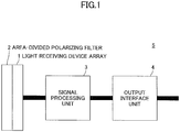
- Fig. 1 is a block diagram schematically illustrating the entire configuration of the imaging apparatus according to the present embodiment.
- an imaging apparatus 5 of the present embodiment includes a light receiving device array 1, an area-divided polarizing filter 2, a signal processing unit 3, and an output interface unit 4.
- the area-divided polarizing filter 2 and the signal processing unit 3 serve as a light transmissive filter and an arithmetic processing unit, respectively.
- the light receiving device array 1 has light receiving devices arranged two-dimensionally in rows and columns.
- a CCD, MOS, CMOS, or the like may be used as the light receiving device array 1.
- the area-divided polarizing filter 2 is situated in front of the light receiving device array 1 on an optical path through which the light receiving device array 1 receives light.
- the signal processing unit 3 receives image data output from the light receiving device array 1, and produces image data that are equivalent to data obtained through respective, separate polarizing filters.
- Polarizing filter sections of the present embodiment serve as light transmissive sections.
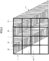
- Fig. 2 is a drawing illustrating an arrangement pattern of the polarizing filter sections of the area-divided polarizing filter that is provided in the imaging apparatus according to the present embodiment.
- the area-divided polarizing filter 2 includes band-shape polarizing filter sections of different types that allow the selective passage of lights having respective, different polarization directions.
- the area-divided polarizing filter 2 includes polarizing filter sections 21 and 22 of different types that allow the selective passage of lights having different polarization directions that are at 90-degree angles relative to each other.
- the two types of diagonal bands illustrated in Fig. 2 are the two types of polarizing filter sections 21 and 22 that correspond to the vertical direction and the horizontal direction, respectively.
- the two types of polarizing filter sections 21 and 22 are arranged alternately (i.e., in sequence) in a width direction.
- the polarizing filter section 21 may be a vertical polarization filter section for which the polarization direction is vertical.
- the polarizing filter section 22 may be a horizontal polarization filter section for which the polarization direction is horizontal.
- the phrase "arranged in sequence" means that the two types A and B are arranged in the order as follows: A, B, A, B, A, B, and so on.
- the area-divided polarizing filter is not limited to the configuration in which two types of polarizing filter sections for transmitting vertically polarized light and horizontally polarized light are provided.
- the area-divided polarizing filter may have three or more types of polarizing filter sections having different polarization directions.
- the phrase "arranged in sequence" means that the three types A, B, and C are arranged in the order as follows: A, B, C, A, B, C, A, B, C, and so on.
- the area-divided polarizing filter 2 is positioned as illustrated in Fig. 2 if the area-divided polarizing filter 2 is not misaligned with the light receiving device array 1. Namely, the area-divided polarizing filter 2 is situated to have a predetermined positional relationship as described below with light receiving devices 10 (or the light receiving sections of the light receiving devices 10), which are squares arranged in a matrix form.
- each of the vertical polarization filter section 21 and the horizontal polarization filter section 22 has a width that is equal to the width of one light receiving device (i.e., one pixel) in the horizontal direction in Fig. 2 .
- the width of the vertical polarization filter section 21 and the width of the horizontal polarization filter section 22 as measured in the row direction in which the rows of the light receiving devices 10 extend are substantially equal to the width of one light receiving device 10 in the row direction.
- each of the vertical polarization filter section 21 and the horizontal polarization filter section 22 has a width that is equal to the total width of two pixels in the vertical direction in Fig. 2 .
- the width of the vertical polarization filter section 21 and the width of the horizontal polarization filter section 22 as measured in the column direction in which the columns of the light receiving devices 10 extend are substantially twice the width of one light receiving device 10 in the column direction.
- the border line between the adjacent polarizing filter sections of the area-divided polarizing filter has a slope equal to 2.
- the border line is diagonally positioned such that the border line crosses two light receiving devices (i.e., two pixels) in the vertical direction while it crosses one light receiving device (i.e., one pixel) in the horizontal direction.
- the arrangement pattern in which the band-shape polarizing filter sections are arranged is a diagonal stripe pattern.
- the width direction in which the band-shape polarizing filter sections are arranged is parallel to neither the horizontal direction (i.e., row direction) of the light receiving device array nor the vertical direction (i.e., column direction) of the light receiving device array.
- the term "width direction" refers to a direction that is perpendicular to the border line.
- the row direction and the column direction merely refer to the two arrangement directions of a two-dimensional array, respectively, and are interchangeable with each other.
- the configuration of the present embodiment thus includes an arrangement that is obtained through 90-degree rotation in which the column direction and the row direction are swapped with each other.
- the present embodiment includes a configuration that is obtained by replacing the horizontal direction (i.e., row direction) and the vertical direction (i.e., column direction) with the vertical direction (i.e., column direction) and the horizontal direction (i.e., row direction), respectively.
- Figs. 3A through 3D and Fig. 4 will be referred to in order to explain how the arrangement pattern of the polarizing filter sections of the area-divided polarizing filter according to the present embodiment is robust against the misalignment that occurs between the polarizing filter sections and the light receiving devices.
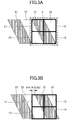
- Figs. 3A through 3D are drawings illustrating examples of misalignments in the horizontal direction (i.e., row direction) between the polarizing filter sections and the light receiving devices.
- Fig. 4 is a graph chart illustrating a cover rate that indicates the size of the overlapping area between a given polarizing filter section and a given light receiving device as a proportion of the area size of the given polarizing filter section with respect to various displacements in the horizontal direction (i.e., row direction).
- Fig. 4 illustrates a cover rate between the vertical polarization filter section and a given light receiving device.
- Fig. 3A, Fig. 3B , Fig. 3C, and Fig. 3D illustrate d being 0 pixel, d being 1/4 pixels (0.25 pixels), d being 1/2 pixels (0.5 pixels), and d being 3/4 pixels (0.75 pixels in the horizontal direction (i.e., row direction)), respectively.
- Fig. 3A, Fig. 3B , Fig. 3C, and Fig. 3D for the sake of simplicity of illustration, four light receiving devices 11 through 14 arranged in two rows and two columns are illustrated with the vertical polarization filter section 21 and the horizontal polarization filter section 22 overlapping these light receiving devices 11 through 14.
- dotted lines II in Fig. 3A corresponds to the area enclosed by dotted lines I in Fig. 2 .
- the vertical polarization filter section 21 is shown in hatching whereas the horizontal polarization filter section 22 is not shown in hatching in Figs. 3A through 3D .
- the light receiving devices 14 and 12 among the light receiving devices 11 through 14 will be described first. Specifically, a description will be given of the cover rate that indicates the size of the overlapping area between the light receiving devices 14 and 12 and the vertical polarization filter section 21 in Figs. 3A through 3D .
- the cover rates of the light receiving devices 14 and 12 with respect to the vertical polarization filter section 21 are 0.75 and 0.25, respectively.
- the cover rates of the light receiving devices 14 and 12 with respect to the vertical polarization filter section 21 are 0.875 and 0.5, respectively.
- the displacement d between the polarizing filter sections and the light receiving devices being 1/2 (0.5) as illustrated in Fig.
- the cover rates of the light receiving devices 14 and 12 with respect to the vertical polarization filter section 21 are 0.75 and 0.75, respectively.
- the cover rates of the light receiving devices 14 and 12 with respect to the vertical polarization filter section 21 are 0.5 and 0.875, respectively.
- Fig. 4 illustrates changes in the cover rate with respect to continuous changes in the displacement d.
- the horizontal axis represents the displacement d in the horizontal direction (i.e., row direction) between the polarizing filter sections and the light receiving devices.
- One unit of the horizontal axis is equal to the width of one light receiving device in the horizontal direction (i.e., row direction).
- the vertical axis represents the cover rate of one light receiving device with respect to the vertical polarization filter section 21.
- a dashed-line curve C1, a solid-line curve C2, a chain-line curve C3, and a dotted-line curve C4 correspond to the light receiving devices 11, 12, 13, and 14 illustrated in Fig. 3A , respectively.
- the cover rate of the vertical polarization filter section 21 indicated by the curve C4 is in the range exceeding 0.75 with respect to the range of the displacement d being 0 to 0.5. Namely, 75% or more of the area of the light receiving device 14 is covered by the vertical polarization filter section 21.
- the curve C4 is downward sloping from left to right in the range of the displacement d being 0.5 to 1.0. Namely, the cover rate of the vertical polarization filter section 21 with respect to the light receiving device 14 decreases with an increase in the displacement d.
- the cover rate of the vertical polarization filter section 21 indicated by the curve C2 is in the range exceeding 0.75 with respect to the range of the displacement d being 0.5 to 1.0.
- the vertical polarization filter section 21 75% or more of the area of the light receiving device 12 is covered by the vertical polarization filter section 21.
- the curves C4 and C2 in the range of the displacement d being 1.0 to 2.0 have the shape that are obtained by flipping the curves C4 and C2 in the range of the displacement d being 0 to 1.0 upside down with respect to a line of symmetry that is the horizontal line situated at a cover rate of 0.5.
- the areas of the light receiving devices 14 and 12 that are not covered by the vertical polarization filter section 21 are covered by the horizontal polarization filter section 22. In the range of the displacement d being 1.0 to 2.0, thus, the cover rate of the horizontal polarization filter section 22 is 75 % or more.
- the light receiving devices 14 and 12 are vertically adjacent to each other.
- the light receiving device 12 on the upper side is covered half by the vertical polarization filter section 21 and half by the horizontal polarization filter section 22 (i.e., when the displacement d is 0.25)
- the light receiving device 14 on the lower side is mainly covered by the vertical polarization filter section 21.
- the light receiving device 14 on the lower side is covered half by the vertical polarization filter section 21 and half by the horizontal polarization filter section 22 (i.e., when the displacement d is 0.75)
- the light receiving device 12 on the upper side is mainly covered by the vertical polarization filter section 21.
- the cover rate of the light receiving device on the right-hand side with respect to coverage by one polarizing filter section is the same as the cover rate of the light receiving device on the left-hand side with respect to coverage by the other polarizing filter section.
- a vicinity area comprised of the four pixels arranged in a 2-pixel-by-2-pixel matrix i.e., in two rows and two columns
- one of these four pixels is mainly covered (i.e., with a cover rate of 0.75 or more) by the vertical polarization filter section 21
- another pixel is mainly covered (i.e., with a cover rate of 0.75 or more) by the horizontal polarization filter section 22. This is true for any displacement d.
- FIG. 5 is a drawing illustrating an example in which the arrangement pattern of an area-divided polarizing filter is a checker board pattern, and is displaced by 1/2 (0.5) in the horizontal direction (i.e., row direction) and in the vertical direction (i.e., column direction), respectively, relative to the light receiving devices.
- Each light receiving device may have a width of 6 micrometers in both the horizontal direction (i.e., row direction) and the vertical direction (i.e., column direction).
- the polarizing filter sections are then displaced relative to the light receiving devices by 3 micrometers (i.e., 1/2 pixels) in the horizontal direction and the vertical direction.
- Fig. 5 four light receiving devices 111, 112, 113, and 114 and four polarizing filter sections are illustrated.
- the four polarizing filter sections include vertical polarization filter sections 121a and 121b and horizontal polarization filter sections 122a and 122b. In the state illustrated in Fig.
- the light received by the light receiving device 114 is an average of lights passing through the four polarizing filter sections 121a, 121b, 122a, and 122b.
- the output of the light receiving device 114 becomes substantially constant regardless of what polarization direction the incoming light has. No information about polarization can thus be obtained.
- the same positional relationships between the light receiving devices and the polarizing filter sections continue in the horizontal direction (i.e., row direction) and in the vertical direction (i.e., column direction). Accordingly, in all the light receiving devices, in addition to the light receiving device 114, the received light becomes an average of the lights passing through the four polarizing filter sections. No information about polarization can thus be obtained.
- neither the cover rate by the vertical polarization filter section nor the cover rate by the horizontal polarization filter section becomes the same in all the four light receiving devices corresponding to the vicinity area comprised of a 2-pixel-by-2-pixel matrix according to the present embodiment. This is true regardless of the displacement d between the light receiving devices and the polarizing filter sections.
- the combination of four pixel outputs is bound to change. Information about polarization can thus be obtained.
- the slope of a border line between adjacent polarizing filter sections relative to a border line between adjacent light receiving devices may be set to a value that is different from 2.
- the width of the filter section in the horizontal direction is one pixel, however, the width of the filter section in the vertical direction becomes 2 pixels.
- This arrangement provides a repetition of the same arrangement in every two pixels in the vertical direction. Such an arrangement can thus help to use a narrow vicinity area, thereby preventing effective resolution from being reduced. Also, such an arrangement can reduce the amount of computation performed by an arithmetic processing unit, which will be described later.
- Fig. 6 is a block diagram illustrating the configuration of the signal processing unit of the imaging apparatus according to the present embodiment.
- the arrangement pattern in which the band-shape polarizing filter sections are arranged is a diagonal stripe pattern. Namely, the arrangement pattern in which the band-shape polarizing filter sections are arranged is the diagonal stripe pattern previously described.
- the width direction in which the band-shape polarizing filter sections are arranged is parallel to neither the horizontal direction (i.e., row direction) of the light receiving device array nor the vertical direction (i.e., column direction) of the light receiving device array.
- the diagonal stripe pattern is employed as the arrangement pattern of the area-divided polarizing filter. This prevents polarization information from being unobtainable when the polarizing filter is misaligned with the light receiving device array.
- one polarizing filter section does not coincide with one light receiving device. Rather, a plurality of polarizing filter sections coincides with one light receiving device. Because of this, image data including only the light component passing through only one polarizing filter section cannot be obtained in a straightforward manner.
- This signal processing method reconstructs plural types of image data corresponding to respective types of polarizing filter sections from image data obtained by taking an image of an object by use of the diagonal stripe arrangement pattern in the area-divided polarizing filter.
- the signal processing unit 3 includes a CPU 31, a DRAM 32, a nonvolatile memory such as a flash memory 33, and an image data input interface 34.
- the signal processing unit 3 executes programs stored in the nonvolatile memory by use of the CPU 31 and the DRAM 32. With this provision, the signal processing unit 3 performs signal processing on the image data received from a light receiving device array through the image data input interface. Data obtained by the signal processing is sent to an output interface unit.
- signal processing is performed by use of software running on the CPU 31.
- Such signal processing may alternatively be performed by a hardware-implemented arithmetic processing circuit.
- Fig. 7 is a flowchart illustrating the signal processing method performed by the imaging apparatus according to the present embodiment.
- the signal processing method of the present embodiment includes a sensitivity measuring step (step S11), a weight factor calculating step (step S12), a weight factor recording step (step S13), an image data acquiring step (step S14), a weighted sum calculating step (step S15), and an image data reconstructing step (step S16).
- step S11 through step S13 are performed in advance. Then, step S14 through step S16 are performed at the time of taking an image of an object.
- the sensitivity measuring step (step S11) is performed in advance.
- polarized light (100% polarization) inclusive of only the vertically polarized light component or only the horizontally polarized light component is shone on the light receiving device array, and image data output from the light receiving device array is input into the signal processing unit.
- the light receiving device array with the area-divided polarizing filter attached thereto is prepared in advance.
- the area-divided polarizing filter may be attached to a face of the light receiving device array by an adhesive agent.
- the positioning, including angular alignment, of the polarizing filter sections of the area-divided polarizing filter relative to the light receiving devices of the light receiving device array does not have to be precise, and may suffice if approximate matching is achieved.
- the light receiving device array with the area-divided polarizing filter attached thereto is combined with the signal processing unit and the output interface unit to prepare the imaging apparatus of the present embodiment.
- the values of the reference image data RI1 and RI2 with respect to a given light receiving device are proportional to the sensitivities of this light receiving device (i.e., pixel) with respect to vertically polarized light and horizontally polarized light, respectively.
- the sensitivities for vertically polarized light and horizontally polarized light are mainly determined by the cover rates of this light receiving device (i.e., pixel) with respect to the vertical polarization filter section and the horizontal polarization filter section, respectively. These sensitivities do not vary after the area-divided polarizing filter is fixedly mounted to the light receiving device array.
- step S12 The weight factor calculating step (step S12) is then performed.
- the signal processing unit calculates weight factors corresponding to respective light receiving devices based on the acquired image data.
- the calculation of the weight factors is performed by using formula (5), which will be described later.
- the weight factor recording step (step S13) is performed.
- the calculated weight factors are stored in memory.
- the memory for storing the weight factors may be the nonvolatile memory such as the flash memory 33.
- step S14 through step S16 are performed at the time of taking an image of an object.
- step S14 the image data acquiring step (step S14) is performed.
- an image of an object is taken to produce image data.
- step S15 the weighted sum calculating step (step S15) is performed.
- arithmetic processing is performed to obtain a weighted sum from the acquired image data by using the stored weight factors.
- the vertically polarized light component of incident light is denoted as L v
- the horizontally polarized light component denoted as L h
- the sensitivity of the vertically polarized light component of a light receiving device i denoted a vi
- the sensitivity of the horizontally polarized light component denoted as a hi
- I i a vi L v + a hi L h
- I 11 I 12 I 13 I 14 a v 11 a h 11 a v 12 a h 12 a v 13 a h 13 a v 14 a h 14 L v L h
- the intensity I i of incident light is determined from the image data output from the light receiving device array.
- the sensitivities a vi and a hi of vertically and horizontally polarized light components of the light receiving device i are known from the data measured in step S11. Only the polarized light components L v and L h of the incident light are unknown.
- the equation (3) represents simultaneous linear equations in which the number of constraint conditions is larger than the number of unknown values L v and L h .
- the matrix M + is calculated for all the light receiving devices by using the equation (5) in step S12, and the calculated matrix M + is then stored in memory in step S13.
- the calculation of the equation (5) is rather complicated. However, it suffices to perform the calculation of the equation (5) only once prior to an actual imaging operation. Namely, it suffices to perform the calculation only once at the time of manufacturing the camera by using a computer separate from the camera to store the results of calculation in memory. The complexity of the calculation thus does not affect the processing speed at the time of taking an image.
- step S16 image data is reconstructed from the obtained weighted sum, followed by sending the reconstructed image data to the output interface unit.
- the polarizing filter sections having a special arrangement pattern is combined with the signal processing to reconstruct plural image data corresponding to the respective polarizing filter sections over the entire area of the image.
- Such reconstruction is achieved even when the accuracy of alignment is not sufficient upon attaching the area-divided polarizing filter to the light receiving device array. Since there is no need to ensure high precision for positional alignment, the manufacturing cost of the imaging apparatus can be reduced.
- the imaging apparatus of the present embodiment can minimize an area of reference used for performing the arithmetic processing to reconstruct image data. This can prevent effective resolution from being reduced, and can also reduce the amount of computation. Since image data is reconstructed by performing simple arithmetic processing, sufficient processing speed at the time of taking an image is achieved. Moreover, the cost of hardware can be reduced. With the use of a proper polarizing filter, plural polarized light images can be taken at once.
- weight factors for the intensities of incident light are obtained from the sensitivities of each light receiving device for vertically and horizontally polarized light components, and such sensitivities are determined based on image data obtained by actually taking an image of a polarized light source or the like.
- the obtained weight factors reflect variations in various characteristics such as the polarization extinction ratio of each polarizing filter sections, light leakage at borders between the polarizing filter sections, and the like, in addition to variation in the cover rate.
- the signal processing method of the present embodiment can thus correct variations in various characteristics in addition to variations in the cover rate.
- the present embodiment employs an area-divided polarizing filter that has two types of polarizing filter sections, i.e., the vertical polarization filter section and the horizontal polarization filter section, which are arranged alternately.
- the polarizing filter sections are not limited to these two types corresponding to the vertical and horizontal polarizations, but may have a configuration in which three or more polarizing filter sections having three or more different polarization directions are arranged in sequence in a repeated manner.
- Fig. 8 is a drawing illustrating an arrangement pattern of the spectral filter sections of the area-divided spectral filter that is provided in the imaging apparatus according to the present embodiment.
- Fig. 8 three types of spectral filter sections are illustrated.
- One spectral filter section is illustrated for each type.
- Fig. 9 is a drawing illustrating the wavelength bands of lights that pass through respective color separation filters constituting the spectral filter sections.
- the imaging apparatus differs from the imaging apparatus of the first embodiment in that a spectral filter is used in place of a polarizing filter.
- the vertical polarization filter section and the horizontal polarization filter section are arranged alternately in the width direction.
- spectral filter sections 23, 24, and 25 comprised of three types of spectral filters having respective spectral transmission characteristics are arranged in sequence in the width direction as illustrated in Fig. 8 .
- the three types of spectral filters may include a first filter F1, a second filter F2, and a third filter F3 having three types of respective transmission wavelength bands as illustrated in Fig. 9 .
- These spectral filters may constitute a color separation filter that allows the passage of RGB colors separately from each other.
- a color separation filter is regarded as a spectral filter in a broader sense, and a description will be given of a spectral filter.
- a spectral filter is used in place of the polarizing filter that is used in the imaging apparatus of the first embodiment.
- the configurations of the light receiving device array, the signal processing unit, and the output interface unit are the same as those described in connection with the block diagram illustrated in Fig. 1 in reference to the first embodiment.
- the signal processing unit of the present embodiment serves as the arithmetic processing unit.
- the area-divided spectral filter and the spectral filter sections of the present embodiment serve as a light transmissive filter and light transmissive sections, respectively.
- each filter section of an area-divided spectral filter 2a of the imaging apparatus has a width equal to the width of one pixel in the horizontal direction (i.e., row direction) as in the first embodiment.
- the border lines between the spectral filter sections 23, 24, and 25 of the area-divided spectral filter 2a have a slope equal to 2.
- the three types of spectral filter sections 23, 24, and 25 are the first filter F1, the second filter F2, and the third filter F3, respectively, which are arranged in sequence in a repeated manner in the width direction.
- the shape of the spectral filter sections 23, 24, and 25 is substantially the same as the shape of the polarizing filter sections 21 and 22 used in the first embodiment.
- Changes in the cover rate with respect to changes in the displacement are substantially the same as those of the polarizing filter sections of the first embodiment described in connection with Fig. 4 .
- the signal processing method of the imaging apparatus is also substantially the same as the signal processing method used in the first embodiment.
- a reference image may be produced by taking an image of an object having uniform luminance with respect to each of the three types of spectral distribution.
- an area of reference is comprised of four light receiving devices (i.e., pixels) having two rows and two columns inclusive of a light receiving device of interest.
- an area of reference is comprised of 6 light receiving devices (i.e., pixels) having two rows and three columns.
- the matrix M appearing in the equation (3) described in the first embodiment is replaced with a matrix M having 6 rows and 2 columns.
- the pseudo inverse matrix M + is obtained by use of the equation (5) described in the first embodiment.
- each spectral filter section may properly be selected, so that a camera for producing spectral images having special spectral characteristics, such as images in the infrared region, may be provided.
- a proper spectral filter plural spectral images can be taken at once.
- the light transmissive filter may include light transmissive sections for transmitting lights that differ from each other in at least one of the three characteristics of light, i.e., wavelength, amplitude (i.e., intensity), and wave vibration direction (i.e., polarization direction).
- the light transmissive filter of the first embodiment provides different light transmissive characteristics that allow the selective passage of lights different from each other in the vibration direction (i.e., polarization direction).
- the light transmissive filter of the second embodiment provides different light transmissive characteristics that allow the selective passage of lights different from each other in the wavelength.
- the light transmissive filter may provide different light transmissive characteristics that allow the selective passage of lights different from each other in the intensity (i.e., amplitude).
Landscapes
- Physics & Mathematics (AREA)
- General Physics & Mathematics (AREA)
- Optics & Photonics (AREA)
- Engineering & Computer Science (AREA)
- Multimedia (AREA)
- Signal Processing (AREA)
- Polarising Elements (AREA)
- Studio Devices (AREA)
- Blocking Light For Cameras (AREA)
- Optical Filters (AREA)
- Optical Elements Other Than Lenses (AREA)
- Color Television Image Signal Generators (AREA)
- Photometry And Measurement Of Optical Pulse Characteristics (AREA)
Description
- The disclosures herein relate to an imaging apparatus that is provided with a light transmissive filter having a plurality of polarizing filters or color separation filters arranged therein, and that produces image signals by imaging an object.
- In digital cameras or the like, an imaging apparatus takes an image of an object to produce image signals, and may separate the image signals into image data of different wavelength bands. In other examples, an imaging apparatus takes an image of an object to produce image signals, and may separate the image signals into image data of different polarization components. This may be performed for the purpose of enhancing the contrast of the imaged object by removing unnecessary polarization components. Such imaging apparatuses may use a light receiving device array in which light receiving devices of the same type are arranged, and may separate incoming light into light components having different polarization directions or different wavelength bands.
- For example, an area-divided-type filter that has its entire area divided into plural types, each allowing the passage of light having a different characteristic, may be disposed in front of a light receiving device array such as a CCD (Charge Coupled Device), a CMOS (Complementary Metal Oxide Semiconductor), or the like. Signal processing is then performed on image signal data output from the light receiving devices. With this arrangement, a plurality of image signals are obtained as if light receiving devices of different types corresponding to light transmissive filters of respective, different characteristics were provided.
- In one example, a color filter may be disposed in front of a light receiving device array such as a CCD. This color filter may include spectral filters (hereinafter referred to as "spectral filter sections") having different light transmission wavelength bands disposed in a predetermined arrangement pattern as in the case of a color separation filter (i.e., area-divided spectral filter), in which areas are divided into R (red), G (green), and B (blue). The light receiving device array is used to produce image signal data of respective colors. Such a configuration is disclosed in Japanese Patent Application Publication No.
2007-086720 - In another example, a polarizing filter may be disposed in front of a light receiving device array such as a CCD. This polarizing filter may be an area-divided polarizing filter that includes plural polarizing filters (hereinafter referred to as "polarizing filter sections") having different polarization directions disposed in a predetermined arrangement pattern. A single image signal obtained by imaging an object is separated according to polarization directions to produce plural image signals. Such a configuration is disclosed in Japanese Patent No.
3771054 - The imaging apparatuses as described above have the following problems.
- In such imaging apparatuses, light received by a single light receiving device corresponding to a single pixel of an image needs to have passed only through one of the plural light transmissive filters (hereinafter referred to as "light transmissive filter sections"). To this end, the shape and size of each light receiving device need to match the shape and size of each light transmissive filter section if the light receiving devices are provided in one-to-one correspondence to the light transmissive filter sections.
- In an imaging apparatus, a light transmissive filter provided as a separate unit is attached by an adhesive agent or the like to the front face of a light receiving device array such as a CCD or CMOS. Accordingly, the provision of filter sections having shapes and sizes that match those of the light receiving devices alone is not sufficient. There is an additional requirement that the light transmissive filter sections need to be accurately aligned with the light receiving array.
- If the light transmissive filter sections are displaced relative to the light receiving devices, a single light receiving device may receive light through plural polarizing filter sections having different polarization characteristics. The image signal data output from this light receiving device is different from what is intended as polarized image data. Polarized image data may not be obtained at all depending on the ratio of mixing of lights.
- If the light transmissive filter is displaced by rotation relative to the light receiving devices, such a displacement may be regarded as a parallel displacement in a small area of interest for a small rotation angle. In the same manner as described above, such an arrangement gives rise to a problem in that polarization information may not be properly obtained.
- These problems that result from the use of a polarizing filter in which plural polarizing filter sections are arranged as an array also occur in the case of a spectral filter in which spectral filter sections are arranged as an array. If the position of a color separation filter is misaligned with the light receiving devices, image signal data produced by a light receiving device ends up being an average of image signals corresponding to lights passing through the respective RGB color separation filters. This gives rise to a problem in that color image information is not properly obtained.
- Accordingly, there may be a need for an imaging apparatus that can reproduce image signal data corresponding to respective light transmissive filter sections even when the accuracy of alignment of the light transmissive filter disposed in front of light receiving devices is not sufficient.
-
JP S57-188188 A -
EP 2 034 743 A1 -
US-5,283,634 A relates to a Luminance signal correcting method. In a method for correcting a luminance signal of a single-plate type color camera which is arranged to read out signals for three primary colors, red, green and blue, by using a solid-state image sensor and to separate and take out the luminance signal and color difference signals, a correction circuit is used for correcting the luminance signal with a correction signal which is formed from the color difference signals, and the correction signal is formed by selecting one of the color difference signals which has the largest value among the color difference signals. - The invention is defined by the subject-matter of
independent claim 1. The dependent claims are directed to advantageous embodiments. - Advantageously, it is provided an imaging apparatus that substantially eliminates one or more problems caused by the limitations and disadvantages of the related art.
- Advantageously, an imaging apparatus includes a light receiving device array having light receiving devices two-dimensionally arranged in both a row direction and a column direction, and a light transmissive filter disposed in front of the light receiving device array, wherein the light transmissive filter includes plural types of band-shape light transmissive sections having respective, different light transmissive characteristics, and the plural types of band-shape light transmissive sections are arranged in sequence in a width direction thereof.
- Advantageously, an imaging apparatus includes a light receiving device array having light receiving devices two-dimensionally arranged in both a row direction and a column direction, and a light transmissive filter disposed in front of the light receiving device array, wherein the light transmissive filter includes plural types of band-shape light transmissive sections having respective, different light transmissive characteristics, and the plural types of band-shape light transmissive sections are arranged in sequence in a width direction thereof, wherein a direction perpendicular to a border line between the light transmissive sections is parallel to neither the row direction nor the column direction in which the light receiving devices are arranged, and wherein a width of the light transmissive sections as measured in the row direction in which the light receiving devices are arranged is substantially equal to a width of one light receiving device as measured in the row direction.
- Advantageously, an imaging apparatus includes a light receiving device array having light receiving devices two-dimensionally arranged in both a row direction and a column direction; a light transmissive filter disposed in front of the light receiving device array, and an arithmetic processing unit configured to perform arithmetic processing on image data output from the light receiving devices, wherein the light transmissive filter includes plural types of band-shape light transmissive sections having respective, different light transmissive characteristics, and the plural types of band-shape light transmissive sections are arranged in sequence in a width direction thereof, and wherein the arithmetic processing is performed to obtain a weighted sum of image data output from a plurality of light receiving devices by using weight factors calculated in advance.
- Advantageously, an imaging apparatus in which a light transmissive filter having different types of light transmissive sections is disposed in front of light receiving devices can reproduce image data corresponding to the respective light transmissive sections over the entire area of the image even when the accuracy of alignment of the light transmissive filter relative to the light receiving devices is not sufficient.
- Other objects and further features of embodiments will be apparent from the following detailed description when read in conjunction with the accompanying drawings, in which:
-
Fig. 1 is a block diagram schematically illustrating the entire configuration of an imaging apparatus according to a first embodiment; -
Fig. 2 is a drawing illustrating an arrangement pattern of polarizing filter sections of a area-divided polarizing filter that is provided in the imaging apparatus according to the first embodiment; -
Figs. 3A through 3D are drawings illustrating examples of misalignments in the horizontal direction (i.e., row direction) between the polarizing filter sections and the light receiving devices; -
Fig. 4 is a graph chart illustrating a cover rate that indicates the size of the overlapping area between a given polarizing filter section and a given light receiving device as a proportion of the area size of the given polarizing filter section with respect to various displacements in the horizontal direction (i.e., row direction); -
Fig. 5 is a drawing illustrating an example in which the arrangement pattern of an area-divided polarizing filter is a checker board pattern, and is displaced by 1/2 (0.5) in the horizontal direction (i.e., row direction) and in the vertical direction (i.e., column direction), respectively, relative to the light receiving devices; -
Fig. 6 is a block diagram illustrating the configuration of a signal processing unit of the imaging apparatus according to the first embodiment; -
Fig. 7 is a flowchart illustrating a signal processing method performed by the imaging apparatus according to the first embodiment; -
Fig. 8 is a drawing illustrating an arrangement pattern of spectral filter sections of a area-divided spectral filter that is provided in the imaging apparatus according to a second embodiment; and -
Fig. 9 is a drawing illustrating the wavelength bands of lights that pass through respective color separation filters constituting the spectral filter sections. - In the following, embodiments will be described by referring to the accompanying drawings. The first embodiment is regarded as the preferred embodiment for carrying out the invention.
- In the following, a description will be given of an imaging apparatus according to a first embodiment by referring to
Fig. 1 through Fig. 6 . - The imaging apparatus of the present embodiment takes an image of an object once by using a pair of a light receiving device array and an area-divided polarizing filter. The imaging device then reconstructs two image data corresponding to the vertical polarization component and the horizontal polarization component, respectively, from the obtained original image data.
- A description will first be given of the entire configuration of the present embodiment by referring to
Fig. 1. Fig. 1 is a block diagram schematically illustrating the entire configuration of the imaging apparatus according to the present embodiment. - As illustrated in
Fig. 1 , animaging apparatus 5 of the present embodiment includes a lightreceiving device array 1, an area-dividedpolarizing filter 2, asignal processing unit 3, and anoutput interface unit 4. - The area-divided
polarizing filter 2 and thesignal processing unit 3 serve as a light transmissive filter and an arithmetic processing unit, respectively. - The light
receiving device array 1 has light receiving devices arranged two-dimensionally in rows and columns. A CCD, MOS, CMOS, or the like may be used as the lightreceiving device array 1. The area-dividedpolarizing filter 2 is situated in front of the lightreceiving device array 1 on an optical path through which the lightreceiving device array 1 receives light. Thesignal processing unit 3 receives image data output from the lightreceiving device array 1, and produces image data that are equivalent to data obtained through respective, separate polarizing filters. - Polarizing filter sections of the present embodiment serve as light transmissive sections.
- In the following, the area-divided polarizing filter of the imaging apparatus according to the present embodiment will be described by referring to
Fig. 2. Fig. 2 is a drawing illustrating an arrangement pattern of the polarizing filter sections of the area-divided polarizing filter that is provided in the imaging apparatus according to the present embodiment. - The area-divided
polarizing filter 2 includes band-shape polarizing filter sections of different types that allow the selective passage of lights having respective, different polarization directions. Specifically, as illustrated inFig. 2 , the area-dividedpolarizing filter 2 includespolarizing filter sections Fig. 2 are the two types ofpolarizing filter sections polarizing filter sections polarizing filter section 21 may be a vertical polarization filter section for which the polarization direction is vertical. Further, thepolarizing filter section 22 may be a horizontal polarization filter section for which the polarization direction is horizontal. - In the example illustrated in the present embodiment, there are two types of polarizing filter sections. In such a case, the phrase "arranged in sequence" means that the two types A and B are arranged in the order as follows: A, B, A, B, A, B, and so on.
- The area-divided polarizing filter is not limited to the configuration in which two types of polarizing filter sections for transmitting vertically polarized light and horizontally polarized light are provided. The area-divided polarizing filter may have three or more types of polarizing filter sections having different polarization directions. In the case in which there are three types of polarizing filter sections provided, for example, the phrase "arranged in sequence" means that the three types A, B, and C are arranged in the order as follows: A, B, C, A, B, C, A, B, C, and so on.
- The area-divided
polarizing filter 2 is positioned as illustrated inFig. 2 if the area-dividedpolarizing filter 2 is not misaligned with the lightreceiving device array 1. Namely, the area-dividedpolarizing filter 2 is situated to have a predetermined positional relationship as described below with light receiving devices 10 (or the light receiving sections of the light receiving devices 10), which are squares arranged in a matrix form. - Specifically, each of the vertical
polarization filter section 21 and the horizontalpolarization filter section 22 has a width that is equal to the width of one light receiving device (i.e., one pixel) in the horizontal direction inFig. 2 . Namely, the width of the verticalpolarization filter section 21 and the width of the horizontalpolarization filter section 22 as measured in the row direction in which the rows of thelight receiving devices 10 extend are substantially equal to the width of onelight receiving device 10 in the row direction. Further, each of the verticalpolarization filter section 21 and the horizontalpolarization filter section 22 has a width that is equal to the total width of two pixels in the vertical direction inFig. 2 . Namely, the width of the verticalpolarization filter section 21 and the width of the horizontalpolarization filter section 22 as measured in the column direction in which the columns of thelight receiving devices 10 extend are substantially twice the width of onelight receiving device 10 in the column direction. Accordingly, the border line between the adjacent polarizing filter sections of the area-divided polarizing filter has a slope equal to 2. In other words, the border line is diagonally positioned such that the border line crosses two light receiving devices (i.e., two pixels) in the vertical direction while it crosses one light receiving device (i.e., one pixel) in the horizontal direction. - In this manner, the arrangement pattern in which the band-shape polarizing filter sections are arranged is a diagonal stripe pattern. The width direction in which the band-shape polarizing filter sections are arranged is parallel to neither the horizontal direction (i.e., row direction) of the light receiving device array nor the vertical direction (i.e., column direction) of the light receiving device array. Here, the term "width direction" refers to a direction that is perpendicular to the border line.
- In the present embodiment, the row direction and the column direction merely refer to the two arrangement directions of a two-dimensional array, respectively, and are interchangeable with each other. The configuration of the present embodiment thus includes an arrangement that is obtained through 90-degree rotation in which the column direction and the row direction are swapped with each other. Namely, the present embodiment includes a configuration that is obtained by replacing the horizontal direction (i.e., row direction) and the vertical direction (i.e., column direction) with the vertical direction (i.e., column direction) and the horizontal direction (i.e., row direction), respectively.
- In the following,
Figs. 3A through 3D andFig. 4 will be referred to in order to explain how the arrangement pattern of the polarizing filter sections of the area-divided polarizing filter according to the present embodiment is robust against the misalignment that occurs between the polarizing filter sections and the light receiving devices. -
Figs. 3A through 3D are drawings illustrating examples of misalignments in the horizontal direction (i.e., row direction) between the polarizing filter sections and the light receiving devices.Fig. 4 is a graph chart illustrating a cover rate that indicates the size of the overlapping area between a given polarizing filter section and a given light receiving device as a proportion of the area size of the given polarizing filter section with respect to various displacements in the horizontal direction (i.e., row direction). Specifically,Fig. 4 illustrates a cover rate between the vertical polarization filter section and a given light receiving device. - With "d" denoting a relative displacement between the polarizing filter sections and the light receiving devices,
Fig. 3A, Fig. 3B ,Fig. 3C, and Fig. 3D illustrate d being 0 pixel, d being 1/4 pixels (0.25 pixels), d being 1/2 pixels (0.5 pixels), and d being 3/4 pixels (0.75 pixels in the horizontal direction (i.e., row direction)), respectively. InFig. 3A, Fig. 3B ,Fig. 3C, and Fig. 3D , for the sake of simplicity of illustration, fourlight receiving devices 11 through 14 arranged in two rows and two columns are illustrated with the verticalpolarization filter section 21 and the horizontalpolarization filter section 22 overlapping theselight receiving devices 11 through 14. The area enclosed by dotted lines II inFig. 3A corresponds to the area enclosed by dotted lines I inFig. 2 . Further, for the sake of providing an easily viewable illustration, the verticalpolarization filter section 21 is shown in hatching whereas the horizontalpolarization filter section 22 is not shown in hatching inFigs. 3A through 3D . - The
light receiving devices light receiving devices 11 through 14 will be described first. Specifically, a description will be given of the cover rate that indicates the size of the overlapping area between thelight receiving devices polarization filter section 21 inFigs. 3A through 3D . - In the case of the displacement d between the polarizing filter sections and the light receiving devices being 0 as illustrated in
Fig. 3A , the cover rates of thelight receiving devices polarization filter section 21 are 0.75 and 0.25, respectively. In the case of the displacement d between the polarizing filter sections and the light receiving devices being 1/4 (0.25) as illustrated inFig. 3B , the cover rates of thelight receiving devices polarization filter section 21 are 0.875 and 0.5, respectively. In the case of the displacement d between the polarizing filter sections and the light receiving devices being 1/2 (0.5) as illustrated inFig. 3C , the cover rates of thelight receiving devices polarization filter section 21 are 0.75 and 0.75, respectively. In the case of the displacement d between the polarizing filter sections and the light receiving devices being 3/4 (0.75) as illustrated inFig. 3D , the cover rates of thelight receiving devices polarization filter section 21 are 0.5 and 0.875, respectively. -
Fig. 4 illustrates changes in the cover rate with respect to continuous changes in the displacement d. InFig. 4 , the horizontal axis represents the displacement d in the horizontal direction (i.e., row direction) between the polarizing filter sections and the light receiving devices. One unit of the horizontal axis is equal to the width of one light receiving device in the horizontal direction (i.e., row direction). The vertical axis represents the cover rate of one light receiving device with respect to the verticalpolarization filter section 21. InFig. 4 , a dashed-line curve C1, a solid-line curve C2, a chain-line curve C3, and a dotted-line curve C4 correspond to thelight receiving devices Fig. 3A , respectively. - By referring to
Fig. 4 , a description will be given of the relationship between displacements and the cover rates of the vertical polarization filter section with respect to thelight receiving devices light receiving devices 11 through 14. - As illustrated in
Fig. 4 , the cover rate of the verticalpolarization filter section 21 indicated by the curve C4 is in the range exceeding 0.75 with respect to the range of the displacement d being 0 to 0.5. Namely, 75% or more of the area of thelight receiving device 14 is covered by the verticalpolarization filter section 21. The curve C4 is downward sloping from left to right in the range of the displacement d being 0.5 to 1.0. Namely, the cover rate of the verticalpolarization filter section 21 with respect to thelight receiving device 14 decreases with an increase in the displacement d. The cover rate of the verticalpolarization filter section 21 indicated by the curve C2 is in the range exceeding 0.75 with respect to the range of the displacement d being 0.5 to 1.0. Namely, 75% or more of the area of thelight receiving device 12 is covered by the verticalpolarization filter section 21. The curves C4 and C2 in the range of the displacement d being 1.0 to 2.0 have the shape that are obtained by flipping the curves C4 and C2 in the range of the displacement d being 0 to 1.0 upside down with respect to a line of symmetry that is the horizontal line situated at a cover rate of 0.5. The areas of thelight receiving devices polarization filter section 21 are covered by the horizontalpolarization filter section 22. In the range of the displacement d being 1.0 to 2.0, thus, the cover rate of the horizontalpolarization filter section 22 is 75 % or more. - The
light receiving devices light receiving device 12 on the upper side is covered half by the verticalpolarization filter section 21 and half by the horizontal polarization filter section 22 (i.e., when the displacement d is 0.25), thelight receiving device 14 on the lower side is mainly covered by the verticalpolarization filter section 21. When thelight receiving device 14 on the lower side is covered half by the verticalpolarization filter section 21 and half by the horizontal polarization filter section 22 (i.e., when the displacement d is 0.75), thelight receiving device 12 on the upper side is mainly covered by the verticalpolarization filter section 21. With respect to two light receiving devices that are horizontally adjacent to each other, the cover rate of the light receiving device on the right-hand side with respect to coverage by one polarizing filter section is the same as the cover rate of the light receiving device on the left-hand side with respect to coverage by the other polarizing filter section. In respect of a vicinity area comprised of the four pixels arranged in a 2-pixel-by-2-pixel matrix (i.e., in two rows and two columns), therefore, one of these four pixels is mainly covered (i.e., with a cover rate of 0.75 or more) by the verticalpolarization filter section 21, and another pixel is mainly covered (i.e., with a cover rate of 0.75 or more) by the horizontalpolarization filter section 22. This is true for any displacement d. - Such an advantage described above is not obtained if the area-divided polarizing filter has other arrangement patterns. A checker board pattern will be compared with the present embodiment by referring to
Fig. 5. Fig. 5 is a drawing illustrating an example in which the arrangement pattern of an area-divided polarizing filter is a checker board pattern, and is displaced by 1/2 (0.5) in the horizontal direction (i.e., row direction) and in the vertical direction (i.e., column direction), respectively, relative to the light receiving devices. - Each light receiving device may have a width of 6 micrometers in both the horizontal direction (i.e., row direction) and the vertical direction (i.e., column direction). The polarizing filter sections are then displaced relative to the light receiving devices by 3 micrometers (i.e., 1/2 pixels) in the horizontal direction and the vertical direction. In
Fig. 5 , fourlight receiving devices polarization filter sections polarization filter sections Fig. 5 , the light received by thelight receiving device 114 is an average of lights passing through the fourpolarizing filter sections light receiving device 114 becomes substantially constant regardless of what polarization direction the incoming light has. No information about polarization can thus be obtained. The same positional relationships between the light receiving devices and the polarizing filter sections continue in the horizontal direction (i.e., row direction) and in the vertical direction (i.e., column direction). Accordingly, in all the light receiving devices, in addition to thelight receiving device 114, the received light becomes an average of the lights passing through the four polarizing filter sections. No information about polarization can thus be obtained. - In contrast to what is described above, neither the cover rate by the vertical polarization filter section nor the cover rate by the horizontal polarization filter section becomes the same in all the four light receiving devices corresponding to the vicinity area comprised of a 2-pixel-by-2-pixel matrix according to the present embodiment. This is true regardless of the displacement d between the light receiving devices and the polarizing filter sections. When the polarization direction of incoming light changes, thus, the combination of four pixel outputs is bound to change. Information about polarization can thus be obtained.
- The slope of a border line between adjacent polarizing filter sections relative to a border line between adjacent light receiving devices may be set to a value that is different from 2. When the slope is 2 and the width of the filter section in the horizontal direction is one pixel, however, the width of the filter section in the vertical direction becomes 2 pixels. This arrangement provides a repetition of the same arrangement in every two pixels in the vertical direction. Such an arrangement can thus help to use a narrow vicinity area, thereby preventing effective resolution from being reduced. Also, such an arrangement can reduce the amount of computation performed by an arithmetic processing unit, which will be described later.
- The above description has been provided with respect to a case in which the area-divided polarizing filter is displaced relative to the light receiving device array in the horizontal direction (i.e., row direction). The same arguments also apply in the case of the area-divided polarizing filter being displaced relative to the light receiving device array in the vertical direction (i.e., column direction).
- Further, rotational displacement by a small angle can be approximated by parallel displacement in the vicinity area. The same arguments as those described above can thus apply.
- In the following, a description will be given of a signal processing method that reconstructs image data of each filter component from image data obtained by use of the above-described arrangement pattern by referring to
Fig. 6. Fig. 6 is a block diagram illustrating the configuration of the signal processing unit of the imaging apparatus according to the present embodiment. - As previously described, the arrangement pattern in which the band-shape polarizing filter sections are arranged is a diagonal stripe pattern. Namely, the arrangement pattern in which the band-shape polarizing filter sections are arranged is the diagonal stripe pattern previously described. The width direction in which the band-shape polarizing filter sections are arranged is parallel to neither the horizontal direction (i.e., row direction) of the light receiving device array nor the vertical direction (i.e., column direction) of the light receiving device array.
- The diagonal stripe pattern is employed as the arrangement pattern of the area-divided polarizing filter. This prevents polarization information from being unobtainable when the polarizing filter is misaligned with the light receiving device array.
- In the arrangement pattern of the polarizing filter sections having the diagonal stripe pattern, however, one polarizing filter section does not coincide with one light receiving device. Rather, a plurality of polarizing filter sections coincides with one light receiving device. Because of this, image data including only the light component passing through only one polarizing filter section cannot be obtained in a straightforward manner.
- In consideration of this, a signal processing method as will be described below is performed. This signal processing method reconstructs plural types of image data corresponding to respective types of polarizing filter sections from image data obtained by taking an image of an object by use of the diagonal stripe arrangement pattern in the area-divided polarizing filter.
- As illustrated in
Fig. 6 , thesignal processing unit 3 includes aCPU 31, aDRAM 32, a nonvolatile memory such as aflash memory 33, and an imagedata input interface 34. Thesignal processing unit 3 executes programs stored in the nonvolatile memory by use of theCPU 31 and theDRAM 32. With this provision, thesignal processing unit 3 performs signal processing on the image data received from a light receiving device array through the image data input interface. Data obtained by the signal processing is sent to an output interface unit. - In this example, signal processing is performed by use of software running on the
CPU 31. Such signal processing may alternatively be performed by a hardware-implemented arithmetic processing circuit. - In the following, a description will be given of the signal processing method performed by the imaging apparatus according to the present embodiment by referring to
Fig. 7. Fig. 7 is a flowchart illustrating the signal processing method performed by the imaging apparatus according to the present embodiment. - As illustrated in
Fig. 7 , the signal processing method of the present embodiment includes a sensitivity measuring step (step S11), a weight factor calculating step (step S12), a weight factor recording step (step S13), an image data acquiring step (step S14), a weighted sum calculating step (step S15), and an image data reconstructing step (step S16). - In the signal processing method of the present embodiment, step S11 through step S13 are performed in advance. Then, step S14 through step S16 are performed at the time of taking an image of an object.
- As described above, the sensitivity measuring step (step S11) is performed in advance. In this step S11, polarized light (100% polarization) inclusive of only the vertically polarized light component or only the horizontally polarized light component is shone on the light receiving device array, and image data output from the light receiving device array is input into the signal processing unit.
- The light receiving device array with the area-divided polarizing filter attached thereto is prepared in advance. Specifically, the area-divided polarizing filter may be attached to a face of the light receiving device array by an adhesive agent. The positioning, including angular alignment, of the polarizing filter sections of the area-divided polarizing filter relative to the light receiving devices of the light receiving device array does not have to be precise, and may suffice if approximate matching is achieved. The light receiving device array with the area-divided polarizing filter attached thereto is combined with the signal processing unit and the output interface unit to prepare the imaging apparatus of the present embodiment.
- Light with the 100% vertically polarized light component having uniform intensity is then shone on the entire face of the light receiving device array. Output values of the light receiving devices of the light receiving device array are then recorded as reference image data RI1. Subsequently, light with the 100% horizontally polarized light component having uniform intensity is shone on the entire face of the light receiving device array. Output values are then recorded as reference image data RI2.
- The values of the reference image data RI1 and RI2 with respect to a given light receiving device (i.e., pixel) are proportional to the sensitivities of this light receiving device (i.e., pixel) with respect to vertically polarized light and horizontally polarized light, respectively. The sensitivities for vertically polarized light and horizontally polarized light are mainly determined by the cover rates of this light receiving device (i.e., pixel) with respect to the vertical polarization filter section and the horizontal polarization filter section, respectively. These sensitivities do not vary after the area-divided polarizing filter is fixedly mounted to the light receiving device array.
- The weight factor calculating step (step S12) is then performed. In this step S12, the signal processing unit calculates weight factors corresponding to respective light receiving devices based on the acquired image data. The calculation of the weight factors is performed by using formula (5), which will be described later.
- Next, the weight factor recording step (step S13) is performed. In this step S13, the calculated weight factors are stored in memory. The memory for storing the weight factors may be the nonvolatile memory such as the
flash memory 33. - After step S11 through step S13 are performed in advance as described above, step S14 through step S16 are performed at the time of taking an image of an object.
- First, the image data acquiring step (step S14) is performed. In this step S14, an image of an object is taken to produce image data.
- Next, the weighted sum calculating step (step S15) is performed. In this step S15, arithmetic processing is performed to obtain a weighted sum from the acquired image data by using the stored weight factors.
- The vertically polarized light component of incident light is denoted as Lv, the horizontally polarized light component denoted as Lh, the sensitivity of the vertically polarized light component of a light receiving device i denoted avi, and the sensitivity of the horizontally polarized light component denoted as ahi. Intensity Ii of incident light entering the light receiving device i through the area-divided polarizing filter is represented as follows.

- Assuming that the same light enters the adjacent light receiving devices arranged in two rows and two columns, the above equation (1) is satisfied with respect to all of these four light receiving devices I1 through I4. The following equation is thus obtained.

- The left-hand side of the equation (2) is denoted as I, and the two matrices on the right-hand side of the equation (2) are denoted as M and L, respectively, in the order in which they appear. Then, the equation (2) is represented as equation (3) as shown below.

- The intensity Ii of incident light is determined from the image data output from the light receiving device array. The sensitivities avi and ahi of vertically and horizontally polarized light components of the light receiving device i are known from the data measured in step S11. Only the polarized light components Lv and Lh of the incident light are unknown.
- The equation (3) represents simultaneous linear equations in which the number of constraint conditions is larger than the number of unknown values Lv and Lh. Such a problem is solved by applying a pseudo inverse matrix M+ of the matrix M to the equation (3) as follows:


- Depending on the displacement between the polarizing filter sections and the light receiving devices, there are cases in which information about polarization is rather difficult to obtain. Such cases occur when the cover rates of adjacent pixels by a filter section are close to 50% in the pixel area comprised of pixels arranged in two rows and two columns. The use of the arithmetic processing method of the present embodiment, however, allows the solutions for Lv and Lh to be obtained in such a manner as to minimize errors through the use of a pseudo inverse matrix.
- As previously described, the matrix M+ is calculated for all the light receiving devices by using the equation (5) in step S12, and the calculated matrix M+ is then stored in memory in step S13. After this preparation, in step S15, a weighted sum of the image data I=(I11, I12, I13, I14) is calculated with respect to the light receiving devices arranged in two rows and two columns, thereby obtaining the vertically and horizontally polarized light components L= (Lv, Lh) of each light receiving device.
- The calculation of the equation (5) is rather complicated. However, it suffices to perform the calculation of the equation (5) only once prior to an actual imaging operation. Namely, it suffices to perform the calculation only once at the time of manufacturing the camera by using a computer separate from the camera to store the results of calculation in memory. The complexity of the calculation thus does not affect the processing speed at the time of taking an image.
- Lastly, the image data reconstructing step (step S16) is performed. In this step S16, image data is reconstructed from the obtained weighted sum, followed by sending the reconstructed image data to the output interface unit.
- According to the imaging apparatus of the present embodiment, the polarizing filter sections having a special arrangement pattern is combined with the signal processing to reconstruct plural image data corresponding to the respective polarizing filter sections over the entire area of the image. Such reconstruction is achieved even when the accuracy of alignment is not sufficient upon attaching the area-divided polarizing filter to the light receiving device array. Since there is no need to ensure high precision for positional alignment, the manufacturing cost of the imaging apparatus can be reduced.
- Furthermore, the imaging apparatus of the present embodiment can minimize an area of reference used for performing the arithmetic processing to reconstruct image data. This can prevent effective resolution from being reduced, and can also reduce the amount of computation. Since image data is reconstructed by performing simple arithmetic processing, sufficient processing speed at the time of taking an image is achieved. Moreover, the cost of hardware can be reduced. With the use of a proper polarizing filter, plural polarized light images can be taken at once.
- In the arithmetic processing method described above, weight factors for the intensities of incident light are obtained from the sensitivities of each light receiving device for vertically and horizontally polarized light components, and such sensitivities are determined based on image data obtained by actually taking an image of a polarized light source or the like. With this arrangement, the obtained weight factors reflect variations in various characteristics such as the polarization extinction ratio of each polarizing filter sections, light leakage at borders between the polarizing filter sections, and the like, in addition to variation in the cover rate. The signal processing method of the present embodiment can thus correct variations in various characteristics in addition to variations in the cover rate.
- Furthermore, the present embodiment employs an area-divided polarizing filter that has two types of polarizing filter sections, i.e., the vertical polarization filter section and the horizontal polarization filter section, which are arranged alternately. Notwithstanding this example, the polarizing filter sections are not limited to these two types corresponding to the vertical and horizontal polarizations, but may have a configuration in which three or more polarizing filter sections having three or more different polarization directions are arranged in sequence in a repeated manner.
- In the following, a description will be given of an imaging apparatus according to a second embodiment by referring to
Fig. 8 andFig. 9 . -
Fig. 8 is a drawing illustrating an arrangement pattern of the spectral filter sections of the area-divided spectral filter that is provided in the imaging apparatus according to the present embodiment. InFig. 8 , three types of spectral filter sections are illustrated. One spectral filter section is illustrated for each type.Fig. 9 is a drawing illustrating the wavelength bands of lights that pass through respective color separation filters constituting the spectral filter sections. - The imaging apparatus according to the present embodiment differs from the imaging apparatus of the first embodiment in that a spectral filter is used in place of a polarizing filter.
- In the imaging apparatus of the first embodiment, the vertical polarization filter section and the horizontal polarization filter section are arranged alternately in the width direction. In the imaging apparatus of the present embodiment, on the other hand,
spectral filter sections Fig. 8 . The three types of spectral filters may include a first filter F1, a second filter F2, and a third filter F3 having three types of respective transmission wavelength bands as illustrated inFig. 9 . These spectral filters may constitute a color separation filter that allows the passage of RGB colors separately from each other. In the following, a color separation filter is regarded as a spectral filter in a broader sense, and a description will be given of a spectral filter. - In the imaging apparatus according to the present embodiment, a spectral filter is used in place of the polarizing filter that is used in the imaging apparatus of the first embodiment. The configurations of the light receiving device array, the signal processing unit, and the output interface unit are the same as those described in connection with the block diagram illustrated in
Fig. 1 in reference to the first embodiment. - As in the first embodiment, the signal processing unit of the present embodiment serves as the arithmetic processing unit. The area-divided spectral filter and the spectral filter sections of the present embodiment serve as a light transmissive filter and light transmissive sections, respectively.
- As illustrated in
Fig. 8 , each filter section of an area-dividedspectral filter 2a of the imaging apparatus according to the present embodiment has a width equal to the width of one pixel in the horizontal direction (i.e., row direction) as in the first embodiment. The border lines between thespectral filter sections spectral filter 2a have a slope equal to 2. The three types ofspectral filter sections Fig. 8 , the shape of thespectral filter sections polarizing filter sections Fig. 4 . In the filter arrangement pattern of the present embodiment, for each spectral filter, there is at least one light receiving device that has a cover rate of at least 75% in the area comprised of 6 pixels having three pixels in the horizontal direction (i.e., row direction) and two pixels in the vertical direction (i.e., column direction). This is true for any displacement. - The signal processing method of the imaging apparatus according to the present embodiment is also substantially the same as the signal processing method used in the first embodiment. Namely, a reference image may be produced by taking an image of an object having uniform luminance with respect to each of the three types of spectral distribution. In the first embodiment, an area of reference is comprised of four light receiving devices (i.e., pixels) having two rows and two columns inclusive of a light receiving device of interest. In the present embodiment, an area of reference is comprised of 6 light receiving devices (i.e., pixels) having two rows and three columns. In the present embodiment, further, the matrix M appearing in the equation (3) described in the first embodiment is replaced with a matrix M having 6 rows and 2 columns. The pseudo inverse matrix M+ is obtained by use of the equation (5) described in the first embodiment.
- In the present embodiment, further, the transmission spectrum of each spectral filter section may properly be selected, so that a camera for producing spectral images having special spectral characteristics, such as images in the infrared region, may be provided. With the use of a proper spectral filter, plural spectral images can be taken at once.
- Further, the present invention is not limited to these embodiments, but various variations and modifications may be made.
- The light transmissive filter may include light transmissive sections for transmitting lights that differ from each other in at least one of the three characteristics of light, i.e., wavelength, amplitude (i.e., intensity), and wave vibration direction (i.e., polarization direction). The light transmissive filter of the first embodiment provides different light transmissive characteristics that allow the selective passage of lights different from each other in the vibration direction (i.e., polarization direction). The light transmissive filter of the second embodiment provides different light transmissive characteristics that allow the selective passage of lights different from each other in the wavelength. The light transmissive filter may provide different light transmissive characteristics that allow the selective passage of lights different from each other in the intensity (i.e., amplitude).
Claims (7)
- An imaging apparatus (5), comprising:a light receiving device array (1) having light receiving devices (10) two-dimensionally arranged in both a row direction and a column direction;an area-divided polarizing filter (2) having a diagonal stripe pattern disposed in front of the light receiving device array (1),wherein the area-divided polarizing filter (2) includes two types of band-shape polarizing filter sections: vertical polarizing filter sections (21) and horizontal polarizing filter sections (22) which are arranged alternatively in a row direction, wherein each of the vertical polarization filter sections (21) and each of the horizontal polarization filter sections (22) has a width that is equal to the width of one light receiving device in the row direction and wherein the border line between the adjacent polarizing filter sections of the area-divided polarizing filter (2) crosses two light receiving devices in the vertical direction while it crosses one light receiving device in the horizontal directions such that each of the band-shape polarizing filter sections (21, 22) has a slope equal to 2; anda signal processing unit (3) configured to perform arithmetic processing on image data output from the light receiving devices (10) in order to reconstruct for each group of four light receiving devices (11 to 14) arranged in two rows and two columns, the horizontally polarized light component L H and the vertically polarized light component L V of incident light,by using the following formula:

where L = [L V , L H ]T is a matrix containing the horizontally polarized light component L H and the vertically polarized light component L V of incident light where
- The imaging apparatus (5) as claimed in claim 1, wherein a direction perpendicular to a border line between the band-shape polarizing filter sections (21, 22) is parallel to neither the row direction nor the column direction in which the four light receiving devices (11 to 14) are arranged.
- The imaging apparatus (5) as claimed in claim 1,
wherein a direction perpendicular to a border line between the band-shaped polarizing filter sections (21, 22) is parallel to neither the row direction nor the column direction in which the light receiving devices (11 to 14) are arranged,
and wherein a width of the band-shaped polarizing filter sections (21, 22) as measured in the row direction in which the light receiving devices (11 to 14) are arranged is equal to a width of one light receiving device (11 to 14) as measured in the row direction. - The imaging apparatus (5) as claimed in claim 3, wherein a width of the band-shaped polarizing filter sections (21, 22) as measured in the column direction in which the light receiving devices (11 to 14) are arranged is equal to twice a width of one light receiving device (11 to 14) as measured in the column direction.
- The imaging apparatus (5) as claimed in claim 1,
wherein the arithmetic processing is performed to obtain a weighted sum of image data output from the four light receiving devices (11 to 14) by using stored weight factors,
wherein the weight factors correspond to the sensitivity avi and ahi. - The imaging apparatus (5) as claimed in claim 5, wherein the signal processing unit (3) is configured to calculate the weight factors based on image data obtained by taking images, wherein
the light receiving device array must be illuminated respectively by a 100% vertically polarized light component having uniform intensity in order to obtain weight factors avi and by a 100% horizontally
polarized light component having uniform intensity in order to obtain weight factors ahi. - The imaging apparatus (5) as claimed in claim 5, further comprising a memory unit configured to store the weight factors.
Applications Claiming Priority (1)
| Application Number | Priority Date | Filing Date | Title |
|---|---|---|---|
| JP2009159965A JP5446521B2 (en) | 2009-07-06 | 2009-07-06 | Imaging device |
Publications (3)
| Publication Number | Publication Date |
|---|---|
| EP2276262A2 EP2276262A2 (en) | 2011-01-19 |
| EP2276262A3 EP2276262A3 (en) | 2015-04-15 |
| EP2276262B1 true EP2276262B1 (en) | 2017-08-09 |
Family
ID=42320833
Family Applications (1)
| Application Number | Title | Priority Date | Filing Date |
|---|---|---|---|
| EP10167725.0A Not-in-force EP2276262B1 (en) | 2009-07-06 | 2010-06-29 | Image pick-up apparatus with a light transmissive filter |
Country Status (3)
| Country | Link |
|---|---|
| US (1) | US8462435B2 (en) |
| EP (1) | EP2276262B1 (en) |
| JP (1) | JP5446521B2 (en) |
Families Citing this family (12)
| Publication number | Priority date | Publication date | Assignee | Title |
|---|---|---|---|---|
| IL201110A (en) | 2009-09-22 | 2014-08-31 | Vorotec Ltd | Apparatus and method for navigation |
| JP5310483B2 (en) * | 2009-10-28 | 2013-10-09 | 株式会社リコー | Imaging device |
| WO2011104714A1 (en) * | 2010-02-25 | 2011-09-01 | Shlomo Vorovitchik | Light filter with varying polarization angles and processing algorithm |
| US9800805B2 (en) * | 2011-02-02 | 2017-10-24 | The Boeing Company | Frequency selective imaging system |
| JP5708099B2 (en) * | 2011-03-18 | 2015-04-30 | 株式会社リコー | Image processing apparatus and image processing method |
| JP5863005B2 (en) * | 2011-09-01 | 2016-02-16 | 株式会社リコー | Imaging device |
| JP5867806B2 (en) * | 2011-09-16 | 2016-02-24 | 株式会社リコー | Imaging device and object identification device using the same |
| JP5929338B2 (en) * | 2012-03-09 | 2016-06-01 | 株式会社リコー | Imaging device, spectral information creation method |
| JP6264349B2 (en) | 2015-09-16 | 2018-01-24 | トヨタ自動車株式会社 | Vehicle front structure |
| CN106226856A (en) * | 2016-08-03 | 2016-12-14 | 京东方科技集团股份有限公司 | A kind of polaroid and display device |
| US10473903B2 (en) * | 2017-12-28 | 2019-11-12 | Waymo Llc | Single optic for low light and high light level imaging |
| WO2020110362A1 (en) * | 2018-11-26 | 2020-06-04 | 株式会社東海理化電機製作所 | Display board and display device |
Family Cites Families (30)
| Publication number | Priority date | Publication date | Assignee | Title |
|---|---|---|---|---|
| JPS51132832A (en) * | 1975-05-13 | 1976-11-18 | Fuji Photo Film Co Ltd | Correction filters automatic control device |
| JPS57188188A (en) * | 1981-05-14 | 1982-11-19 | Matsushita Electric Ind Co Ltd | Solid-state color image pickup device |
| EP0143357B1 (en) * | 1983-10-31 | 1988-06-08 | Matsushita Electric Industrial Co., Ltd. | Optical device and document reader using the same |
| DE3515020A1 (en) * | 1984-04-28 | 1985-11-07 | Kabushiki Kaisha Toshiba, Kawasaki, Kanagawa | LOCAL FREQUENCY FILTER |
| US4737621A (en) * | 1985-12-06 | 1988-04-12 | Adaptive Optics Assoc., Inc. | Integrated adaptive optical wavefront sensing and compensating system |
| US5283634A (en) * | 1987-06-18 | 1994-02-01 | Canon Kabushiki Kaisha | Luminance signal correcting method |
| JP2892177B2 (en) * | 1991-05-15 | 1999-05-17 | 日本放送協会 | Color solid-state imaging device |
| JPH0755561A (en) * | 1993-08-12 | 1995-03-03 | Fujitsu Ltd | Photosensor |
| US6327085B1 (en) * | 1998-03-31 | 2001-12-04 | Nikon Corporation | Optical filter and optical device provided with this optical filter |
| JP3771054B2 (en) | 1998-07-01 | 2006-04-26 | 株式会社リコー | Image processing apparatus and image processing method |
| JP4027079B2 (en) * | 2001-11-02 | 2007-12-26 | キヤノン株式会社 | Imaging device |
| US7196829B2 (en) * | 2002-01-10 | 2007-03-27 | Micron Technology Inc. | Digital image system and method for combining sensing and image processing on sensor with two-color photo-detector |
| US6940061B2 (en) * | 2002-02-27 | 2005-09-06 | Agilent Technologies, Inc. | Two-color photo-detector and methods for demosaicing a two-color photo-detector array |
| US7098442B2 (en) * | 2003-03-05 | 2006-08-29 | Raytheon Company | Thin micropolarizing filter, and a method for making it |
| JP2005259750A (en) * | 2004-03-09 | 2005-09-22 | Fuji Film Microdevices Co Ltd | Multiple-disk color solid state imaging device and digital camera |
| JP4304483B2 (en) * | 2004-03-24 | 2009-07-29 | 住友金属鉱山株式会社 | Spectroscopic element |
| EP1758404A4 (en) * | 2004-05-26 | 2010-10-27 | Acutelogic Corp | Imaging device |
| DE102004033602A1 (en) * | 2004-07-08 | 2006-02-16 | Carl Zeiss Sms Gmbh | Imaging system for emulation of high-aperture scanner systems |
| US7545422B2 (en) * | 2004-10-27 | 2009-06-09 | Aptina Imaging Corporation | Imaging system |
| JP4902112B2 (en) * | 2004-11-22 | 2012-03-21 | キヤノン株式会社 | Low-pass filter and imaging device |
| US20060268357A1 (en) * | 2005-05-25 | 2006-11-30 | Vook Dietrich W | System and method for processing images using centralized image correction data |
| JP4974543B2 (en) | 2005-08-23 | 2012-07-11 | 株式会社フォトニックラティス | Polarization imaging device |
| JP2007110588A (en) * | 2005-10-17 | 2007-04-26 | Funai Electric Co Ltd | Compound-eye imaging apparatus |
| US7667747B2 (en) * | 2006-03-15 | 2010-02-23 | Qualcomm Incorporated | Processing of sensor values in imaging systems |
| US20080002255A1 (en) * | 2006-07-02 | 2008-01-03 | Amon Tavor | Stereoscopic Display Using a Color Parallax Barrier |
| US7655898B2 (en) * | 2006-11-30 | 2010-02-02 | Cambridge Research & Instrumentation, Inc. | Optical filter assembly with selectable bandwidth and rejection |
| JP4930109B2 (en) * | 2007-03-06 | 2012-05-16 | ソニー株式会社 | Solid-state imaging device, imaging device |
| EP2034743A4 (en) * | 2007-05-31 | 2014-03-05 | Panasonic Corp | Image processing device |
| JP2009049117A (en) * | 2007-08-17 | 2009-03-05 | Fujifilm Corp | Method of forming color filter of solid-state image pickup device, solid-state image pickup device, and pattern mask set for solid-state image pickup device |
| JP5439191B2 (en) * | 2007-12-26 | 2014-03-12 | 株式会社日立製作所 | Optical transceiver module |
-
2009
- 2009-07-06 JP JP2009159965A patent/JP5446521B2/en active Active
-
2010
- 2010-06-23 US US12/821,328 patent/US8462435B2/en active Active
- 2010-06-29 EP EP10167725.0A patent/EP2276262B1/en not_active Not-in-force
Non-Patent Citations (1)
| Title |
|---|
| None * |
Also Published As
| Publication number | Publication date |
|---|---|
| JP5446521B2 (en) | 2014-03-19 |
| US20110002040A1 (en) | 2011-01-06 |
| EP2276262A2 (en) | 2011-01-19 |
| US8462435B2 (en) | 2013-06-11 |
| EP2276262A3 (en) | 2015-04-15 |
| JP2011013630A (en) | 2011-01-20 |
Similar Documents
| Publication | Publication Date | Title |
|---|---|---|
| EP2276262B1 (en) | Image pick-up apparatus with a light transmissive filter | |
| EP2330811B1 (en) | Imaging apparatus with light transmissive filter | |
| CN108780142B (en) | 3D imaging system and method | |
| US8908087B2 (en) | Multiband camera, and multiband image capturing method | |
| EP2160018B1 (en) | Image pickup apparatus | |
| US9848118B2 (en) | Phase detection autofocus using opposing filter masks | |
| US7742087B2 (en) | Image pickup device | |
| JP5927570B2 (en) | Three-dimensional imaging device, light transmission unit, image processing device, and program | |
| WO2011142062A1 (en) | Three-dimensional imaging device | |
| CN115152205A (en) | Image pickup apparatus and method | |
| US9188480B2 (en) | Color filter array and image sensor | |
| CN103004218B (en) | Three-dimensional image pickup device, imaging apparatus, transmittance section and image processing apparatus | |
| US6417950B1 (en) | Three-color imaging on each pixel for increased resolution | |
| JP2012252280A (en) | Imaging apparatus | |
| EP4243435A2 (en) | Plenoptic camera with higher resolution using a controllable birefringent layer | |
| JPWO2020071253A1 (en) | Imaging device | |
| JP5359841B2 (en) | IMAGING DEVICE, IMAGING METHOD, AND COMPUTER-READABLE RECORDING MEDIUM RECORDING PROGRAM FOR EXECUTING THE IMAGING METHOD | |
| JP2004085965A (en) | Stereoscopic image pickup device and stereoscopic display device | |
| Zhang et al. | Spatio-spectral modulation using a binary photomask for compressive chromotomography | |
| JP2000023172A (en) | Image pickup device |
Legal Events
| Date | Code | Title | Description |
|---|---|---|---|
| PUAI | Public reference made under article 153(3) epc to a published international application that has entered the european phase |
Free format text: ORIGINAL CODE: 0009012 |
|
| 17P | Request for examination filed |
Effective date: 20100629 |
|
| AK | Designated contracting states |
Kind code of ref document: A2 Designated state(s): AL AT BE BG CH CY CZ DE DK EE ES FI FR GB GR HR HU IE IS IT LI LT LU LV MC MK MT NL NO PL PT RO SE SI SK SM TR |
|
| AX | Request for extension of the european patent |
Extension state: BA ME RS |
|
| PUAL | Search report despatched |
Free format text: ORIGINAL CODE: 0009013 |
|
| AK | Designated contracting states |
Kind code of ref document: A3 Designated state(s): AL AT BE BG CH CY CZ DE DK EE ES FI FR GB GR HR HU IE IS IT LI LT LU LV MC MK MT NL NO PL PT RO SE SI SK SM TR |
|
| AX | Request for extension of the european patent |
Extension state: BA ME RS |
|
| RIC1 | Information provided on ipc code assigned before grant |
Ipc: H04N 9/04 20060101AFI20150309BHEP Ipc: H04N 9/07 20060101ALI20150309BHEP |
|
| RBV | Designated contracting states (corrected) |
Designated state(s): AL AT BE BG CH CY CZ DE DK EE ES FI FR GB GR HR HU IE IS IT LI LT LU LV MC MK MT NL NO PL PT RO SE SI SK SM TR |
|
| 17Q | First examination report despatched |
Effective date: 20160909 |
|
| REG | Reference to a national code |
Ref country code: DE Ref legal event code: R079 Ref document number: 602010044212 Country of ref document: DE Free format text: PREVIOUS MAIN CLASS: H04N0009040000 Ipc: H04N0005225000 |
|
| GRAP | Despatch of communication of intention to grant a patent |
Free format text: ORIGINAL CODE: EPIDOSNIGR1 |
|
| RIC1 | Information provided on ipc code assigned before grant |
Ipc: H04N 9/07 20060101ALI20170201BHEP Ipc: H04N 5/225 20060101AFI20170201BHEP Ipc: H04N 9/04 20060101ALI20170201BHEP |
|
| INTG | Intention to grant announced |
Effective date: 20170220 |
|
| GRAS | Grant fee paid |
Free format text: ORIGINAL CODE: EPIDOSNIGR3 |
|
| GRAA | (expected) grant |
Free format text: ORIGINAL CODE: 0009210 |
|
| AK | Designated contracting states |
Kind code of ref document: B1 Designated state(s): AL AT BE BG CH CY CZ DE DK EE ES FI FR GB GR HR HU IE IS IT LI LT LU LV MC MK MT NL NO PL PT RO SE SI SK SM TR |
|
| REG | Reference to a national code |
Ref country code: GB Ref legal event code: FG4D |
|
| REG | Reference to a national code |
Ref country code: CH Ref legal event code: EP Ref country code: AT Ref legal event code: REF Ref document number: 917998 Country of ref document: AT Kind code of ref document: T Effective date: 20170815 |
|
| REG | Reference to a national code |
Ref country code: IE Ref legal event code: FG4D |
|
| REG | Reference to a national code |
Ref country code: DE Ref legal event code: R096 Ref document number: 602010044212 Country of ref document: DE |
|
| REG | Reference to a national code |
Ref country code: NL Ref legal event code: MP Effective date: 20170809 |
|
| REG | Reference to a national code |
Ref country code: LT Ref legal event code: MG4D |
|
| REG | Reference to a national code |
Ref country code: AT Ref legal event code: MK05 Ref document number: 917998 Country of ref document: AT Kind code of ref document: T Effective date: 20170809 |
|
| PG25 | Lapsed in a contracting state [announced via postgrant information from national office to epo] |
Ref country code: HR Free format text: LAPSE BECAUSE OF FAILURE TO SUBMIT A TRANSLATION OF THE DESCRIPTION OR TO PAY THE FEE WITHIN THE PRESCRIBED TIME-LIMIT Effective date: 20170809 Ref country code: NO Free format text: LAPSE BECAUSE OF FAILURE TO SUBMIT A TRANSLATION OF THE DESCRIPTION OR TO PAY THE FEE WITHIN THE PRESCRIBED TIME-LIMIT Effective date: 20171109 Ref country code: LT Free format text: LAPSE BECAUSE OF FAILURE TO SUBMIT A TRANSLATION OF THE DESCRIPTION OR TO PAY THE FEE WITHIN THE PRESCRIBED TIME-LIMIT Effective date: 20170809 Ref country code: SE Free format text: LAPSE BECAUSE OF FAILURE TO SUBMIT A TRANSLATION OF THE DESCRIPTION OR TO PAY THE FEE WITHIN THE PRESCRIBED TIME-LIMIT Effective date: 20170809 Ref country code: NL Free format text: LAPSE BECAUSE OF FAILURE TO SUBMIT A TRANSLATION OF THE DESCRIPTION OR TO PAY THE FEE WITHIN THE PRESCRIBED TIME-LIMIT Effective date: 20170809 Ref country code: AT Free format text: LAPSE BECAUSE OF FAILURE TO SUBMIT A TRANSLATION OF THE DESCRIPTION OR TO PAY THE FEE WITHIN THE PRESCRIBED TIME-LIMIT Effective date: 20170809 Ref country code: FI Free format text: LAPSE BECAUSE OF FAILURE TO SUBMIT A TRANSLATION OF THE DESCRIPTION OR TO PAY THE FEE WITHIN THE PRESCRIBED TIME-LIMIT Effective date: 20170809 |
|
| PG25 | Lapsed in a contracting state [announced via postgrant information from national office to epo] |
Ref country code: GR Free format text: LAPSE BECAUSE OF FAILURE TO SUBMIT A TRANSLATION OF THE DESCRIPTION OR TO PAY THE FEE WITHIN THE PRESCRIBED TIME-LIMIT Effective date: 20171110 Ref country code: ES Free format text: LAPSE BECAUSE OF FAILURE TO SUBMIT A TRANSLATION OF THE DESCRIPTION OR TO PAY THE FEE WITHIN THE PRESCRIBED TIME-LIMIT Effective date: 20170809 Ref country code: LV Free format text: LAPSE BECAUSE OF FAILURE TO SUBMIT A TRANSLATION OF THE DESCRIPTION OR TO PAY THE FEE WITHIN THE PRESCRIBED TIME-LIMIT Effective date: 20170809 Ref country code: IS Free format text: LAPSE BECAUSE OF FAILURE TO SUBMIT A TRANSLATION OF THE DESCRIPTION OR TO PAY THE FEE WITHIN THE PRESCRIBED TIME-LIMIT Effective date: 20171209 Ref country code: BG Free format text: LAPSE BECAUSE OF FAILURE TO SUBMIT A TRANSLATION OF THE DESCRIPTION OR TO PAY THE FEE WITHIN THE PRESCRIBED TIME-LIMIT Effective date: 20171109 Ref country code: PL Free format text: LAPSE BECAUSE OF FAILURE TO SUBMIT A TRANSLATION OF THE DESCRIPTION OR TO PAY THE FEE WITHIN THE PRESCRIBED TIME-LIMIT Effective date: 20170809 |
|
| PG25 | Lapsed in a contracting state [announced via postgrant information from national office to epo] |
Ref country code: RO Free format text: LAPSE BECAUSE OF FAILURE TO SUBMIT A TRANSLATION OF THE DESCRIPTION OR TO PAY THE FEE WITHIN THE PRESCRIBED TIME-LIMIT Effective date: 20170809 Ref country code: CZ Free format text: LAPSE BECAUSE OF FAILURE TO SUBMIT A TRANSLATION OF THE DESCRIPTION OR TO PAY THE FEE WITHIN THE PRESCRIBED TIME-LIMIT Effective date: 20170809 Ref country code: DK Free format text: LAPSE BECAUSE OF FAILURE TO SUBMIT A TRANSLATION OF THE DESCRIPTION OR TO PAY THE FEE WITHIN THE PRESCRIBED TIME-LIMIT Effective date: 20170809 |
|
| REG | Reference to a national code |
Ref country code: DE Ref legal event code: R097 Ref document number: 602010044212 Country of ref document: DE |
|
| PG25 | Lapsed in a contracting state [announced via postgrant information from national office to epo] |
Ref country code: SM Free format text: LAPSE BECAUSE OF FAILURE TO SUBMIT A TRANSLATION OF THE DESCRIPTION OR TO PAY THE FEE WITHIN THE PRESCRIBED TIME-LIMIT Effective date: 20170809 Ref country code: EE Free format text: LAPSE BECAUSE OF FAILURE TO SUBMIT A TRANSLATION OF THE DESCRIPTION OR TO PAY THE FEE WITHIN THE PRESCRIBED TIME-LIMIT Effective date: 20170809 Ref country code: SK Free format text: LAPSE BECAUSE OF FAILURE TO SUBMIT A TRANSLATION OF THE DESCRIPTION OR TO PAY THE FEE WITHIN THE PRESCRIBED TIME-LIMIT Effective date: 20170809 Ref country code: IT Free format text: LAPSE BECAUSE OF FAILURE TO SUBMIT A TRANSLATION OF THE DESCRIPTION OR TO PAY THE FEE WITHIN THE PRESCRIBED TIME-LIMIT Effective date: 20170809 |
|
| PLBE | No opposition filed within time limit |
Free format text: ORIGINAL CODE: 0009261 |
|
| STAA | Information on the status of an ep patent application or granted ep patent |
Free format text: STATUS: NO OPPOSITION FILED WITHIN TIME LIMIT |
|
| REG | Reference to a national code |
Ref country code: FR Ref legal event code: PLFP Year of fee payment: 9 |
|
| 26N | No opposition filed |
Effective date: 20180511 |
|
| PG25 | Lapsed in a contracting state [announced via postgrant information from national office to epo] |
Ref country code: SI Free format text: LAPSE BECAUSE OF FAILURE TO SUBMIT A TRANSLATION OF THE DESCRIPTION OR TO PAY THE FEE WITHIN THE PRESCRIBED TIME-LIMIT Effective date: 20170809 |
|
| REG | Reference to a national code |
Ref country code: CH Ref legal event code: PL |
|
| REG | Reference to a national code |
Ref country code: BE Ref legal event code: MM Effective date: 20180630 |
|
| PG25 | Lapsed in a contracting state [announced via postgrant information from national office to epo] |
Ref country code: LU Free format text: LAPSE BECAUSE OF NON-PAYMENT OF DUE FEES Effective date: 20180629 Ref country code: MC Free format text: LAPSE BECAUSE OF FAILURE TO SUBMIT A TRANSLATION OF THE DESCRIPTION OR TO PAY THE FEE WITHIN THE PRESCRIBED TIME-LIMIT Effective date: 20170809 |
|
| REG | Reference to a national code |
Ref country code: IE Ref legal event code: MM4A |
|
| PG25 | Lapsed in a contracting state [announced via postgrant information from national office to epo] |
Ref country code: IE Free format text: LAPSE BECAUSE OF NON-PAYMENT OF DUE FEES Effective date: 20180629 Ref country code: CH Free format text: LAPSE BECAUSE OF NON-PAYMENT OF DUE FEES Effective date: 20180630 Ref country code: LI Free format text: LAPSE BECAUSE OF NON-PAYMENT OF DUE FEES Effective date: 20180630 |
|
| PG25 | Lapsed in a contracting state [announced via postgrant information from national office to epo] |
Ref country code: BE Free format text: LAPSE BECAUSE OF NON-PAYMENT OF DUE FEES Effective date: 20180630 |
|
| PG25 | Lapsed in a contracting state [announced via postgrant information from national office to epo] |
Ref country code: MT Free format text: LAPSE BECAUSE OF NON-PAYMENT OF DUE FEES Effective date: 20180629 |
|
| PG25 | Lapsed in a contracting state [announced via postgrant information from national office to epo] |
Ref country code: TR Free format text: LAPSE BECAUSE OF FAILURE TO SUBMIT A TRANSLATION OF THE DESCRIPTION OR TO PAY THE FEE WITHIN THE PRESCRIBED TIME-LIMIT Effective date: 20170809 |
|
| PG25 | Lapsed in a contracting state [announced via postgrant information from national office to epo] |
Ref country code: PT Free format text: LAPSE BECAUSE OF FAILURE TO SUBMIT A TRANSLATION OF THE DESCRIPTION OR TO PAY THE FEE WITHIN THE PRESCRIBED TIME-LIMIT Effective date: 20170809 Ref country code: HU Free format text: LAPSE BECAUSE OF FAILURE TO SUBMIT A TRANSLATION OF THE DESCRIPTION OR TO PAY THE FEE WITHIN THE PRESCRIBED TIME-LIMIT; INVALID AB INITIO Effective date: 20100629 |
|
| PG25 | Lapsed in a contracting state [announced via postgrant information from national office to epo] |
Ref country code: MK Free format text: LAPSE BECAUSE OF NON-PAYMENT OF DUE FEES Effective date: 20170809 Ref country code: CY Free format text: LAPSE BECAUSE OF FAILURE TO SUBMIT A TRANSLATION OF THE DESCRIPTION OR TO PAY THE FEE WITHIN THE PRESCRIBED TIME-LIMIT Effective date: 20170809 |
|
| PG25 | Lapsed in a contracting state [announced via postgrant information from national office to epo] |
Ref country code: AL Free format text: LAPSE BECAUSE OF FAILURE TO SUBMIT A TRANSLATION OF THE DESCRIPTION OR TO PAY THE FEE WITHIN THE PRESCRIBED TIME-LIMIT Effective date: 20170809 |
|
| PGFP | Annual fee paid to national office [announced via postgrant information from national office to epo] |
Ref country code: DE Payment date: 20210618 Year of fee payment: 12 Ref country code: FR Payment date: 20210622 Year of fee payment: 12 |
|
| PGFP | Annual fee paid to national office [announced via postgrant information from national office to epo] |
Ref country code: GB Payment date: 20210625 Year of fee payment: 12 |
|
| REG | Reference to a national code |
Ref country code: DE Ref legal event code: R079 Ref document number: 602010044212 Country of ref document: DE Free format text: PREVIOUS MAIN CLASS: H04N0005225000 Ipc: H04N0023000000 |
|
| REG | Reference to a national code |
Ref country code: DE Ref legal event code: R119 Ref document number: 602010044212 Country of ref document: DE |
|
| GBPC | Gb: european patent ceased through non-payment of renewal fee |
Effective date: 20220629 |
|
| PG25 | Lapsed in a contracting state [announced via postgrant information from national office to epo] |
Ref country code: FR Free format text: LAPSE BECAUSE OF NON-PAYMENT OF DUE FEES Effective date: 20220630 |
|
| PG25 | Lapsed in a contracting state [announced via postgrant information from national office to epo] |
Ref country code: GB Free format text: LAPSE BECAUSE OF NON-PAYMENT OF DUE FEES Effective date: 20220629 Ref country code: DE Free format text: LAPSE BECAUSE OF NON-PAYMENT OF DUE FEES Effective date: 20230103 |