EP2276260B1 - Système de codage de trames lors d' une commutation de flux d'images à multiples références et vitesses. - Google Patents
Système de codage de trames lors d' une commutation de flux d'images à multiples références et vitesses. Download PDFInfo
- Publication number
- EP2276260B1 EP2276260B1 EP20100180917 EP10180917A EP2276260B1 EP 2276260 B1 EP2276260 B1 EP 2276260B1 EP 20100180917 EP20100180917 EP 20100180917 EP 10180917 A EP10180917 A EP 10180917A EP 2276260 B1 EP2276260 B1 EP 2276260B1
- Authority
- EP
- European Patent Office
- Prior art keywords
- picture
- pictures
- unit
- coded
- memory
- Prior art date
- Legal status (The legal status is an assumption and is not a legal conclusion. Google has not performed a legal analysis and makes no representation as to the accuracy of the status listed.)
- Expired - Lifetime
Links
Images


Classifications
-
- H—ELECTRICITY
- H04—ELECTRIC COMMUNICATION TECHNIQUE
- H04N—PICTORIAL COMMUNICATION, e.g. TELEVISION
- H04N19/00—Methods or arrangements for coding, decoding, compressing or decompressing digital video signals
- H04N19/50—Methods or arrangements for coding, decoding, compressing or decompressing digital video signals using predictive coding
-
- H—ELECTRICITY
- H04—ELECTRIC COMMUNICATION TECHNIQUE
- H04N—PICTORIAL COMMUNICATION, e.g. TELEVISION
- H04N19/00—Methods or arrangements for coding, decoding, compressing or decompressing digital video signals
- H04N19/10—Methods or arrangements for coding, decoding, compressing or decompressing digital video signals using adaptive coding
- H04N19/102—Methods or arrangements for coding, decoding, compressing or decompressing digital video signals using adaptive coding characterised by the element, parameter or selection affected or controlled by the adaptive coding
- H04N19/103—Selection of coding mode or of prediction mode
- H04N19/105—Selection of the reference unit for prediction within a chosen coding or prediction mode, e.g. adaptive choice of position and number of pixels used for prediction
-
- G—PHYSICS
- G11—INFORMATION STORAGE
- G11B—INFORMATION STORAGE BASED ON RELATIVE MOVEMENT BETWEEN RECORD CARRIER AND TRANSDUCER
- G11B27/00—Editing; Indexing; Addressing; Timing or synchronising; Monitoring; Measuring tape travel
- G11B27/10—Indexing; Addressing; Timing or synchronising; Measuring tape travel
- G11B27/102—Programmed access in sequence to addressed parts of tracks of operating record carriers
- G11B27/105—Programmed access in sequence to addressed parts of tracks of operating record carriers of operating discs
-
- H—ELECTRICITY
- H04—ELECTRIC COMMUNICATION TECHNIQUE
- H04N—PICTORIAL COMMUNICATION, e.g. TELEVISION
- H04N19/00—Methods or arrangements for coding, decoding, compressing or decompressing digital video signals
- H04N19/10—Methods or arrangements for coding, decoding, compressing or decompressing digital video signals using adaptive coding
- H04N19/102—Methods or arrangements for coding, decoding, compressing or decompressing digital video signals using adaptive coding characterised by the element, parameter or selection affected or controlled by the adaptive coding
- H04N19/103—Selection of coding mode or of prediction mode
- H04N19/107—Selection of coding mode or of prediction mode between spatial and temporal predictive coding, e.g. picture refresh
-
- H—ELECTRICITY
- H04—ELECTRIC COMMUNICATION TECHNIQUE
- H04N—PICTORIAL COMMUNICATION, e.g. TELEVISION
- H04N19/00—Methods or arrangements for coding, decoding, compressing or decompressing digital video signals
- H04N19/10—Methods or arrangements for coding, decoding, compressing or decompressing digital video signals using adaptive coding
- H04N19/134—Methods or arrangements for coding, decoding, compressing or decompressing digital video signals using adaptive coding characterised by the element, parameter or criterion affecting or controlling the adaptive coding
-
- H—ELECTRICITY
- H04—ELECTRIC COMMUNICATION TECHNIQUE
- H04N—PICTORIAL COMMUNICATION, e.g. TELEVISION
- H04N19/00—Methods or arrangements for coding, decoding, compressing or decompressing digital video signals
- H04N19/10—Methods or arrangements for coding, decoding, compressing or decompressing digital video signals using adaptive coding
- H04N19/169—Methods or arrangements for coding, decoding, compressing or decompressing digital video signals using adaptive coding characterised by the coding unit, i.e. the structural portion or semantic portion of the video signal being the object or the subject of the adaptive coding
- H04N19/17—Methods or arrangements for coding, decoding, compressing or decompressing digital video signals using adaptive coding characterised by the coding unit, i.e. the structural portion or semantic portion of the video signal being the object or the subject of the adaptive coding the unit being an image region, e.g. an object
- H04N19/172—Methods or arrangements for coding, decoding, compressing or decompressing digital video signals using adaptive coding characterised by the coding unit, i.e. the structural portion or semantic portion of the video signal being the object or the subject of the adaptive coding the unit being an image region, e.g. an object the region being a picture, frame or field
-
- H—ELECTRICITY
- H04—ELECTRIC COMMUNICATION TECHNIQUE
- H04N—PICTORIAL COMMUNICATION, e.g. TELEVISION
- H04N19/00—Methods or arrangements for coding, decoding, compressing or decompressing digital video signals
- H04N19/42—Methods or arrangements for coding, decoding, compressing or decompressing digital video signals characterised by implementation details or hardware specially adapted for video compression or decompression, e.g. dedicated software implementation
- H04N19/423—Methods or arrangements for coding, decoding, compressing or decompressing digital video signals characterised by implementation details or hardware specially adapted for video compression or decompression, e.g. dedicated software implementation characterised by memory arrangements
-
- H—ELECTRICITY
- H04—ELECTRIC COMMUNICATION TECHNIQUE
- H04N—PICTORIAL COMMUNICATION, e.g. TELEVISION
- H04N19/00—Methods or arrangements for coding, decoding, compressing or decompressing digital video signals
- H04N19/46—Embedding additional information in the video signal during the compression process
-
- H—ELECTRICITY
- H04—ELECTRIC COMMUNICATION TECHNIQUE
- H04N—PICTORIAL COMMUNICATION, e.g. TELEVISION
- H04N19/00—Methods or arrangements for coding, decoding, compressing or decompressing digital video signals
- H04N19/50—Methods or arrangements for coding, decoding, compressing or decompressing digital video signals using predictive coding
- H04N19/503—Methods or arrangements for coding, decoding, compressing or decompressing digital video signals using predictive coding involving temporal prediction
- H04N19/51—Motion estimation or motion compensation
- H04N19/573—Motion compensation with multiple frame prediction using two or more reference frames in a given prediction direction
-
- H—ELECTRICITY
- H04—ELECTRIC COMMUNICATION TECHNIQUE
- H04N—PICTORIAL COMMUNICATION, e.g. TELEVISION
- H04N19/00—Methods or arrangements for coding, decoding, compressing or decompressing digital video signals
- H04N19/60—Methods or arrangements for coding, decoding, compressing or decompressing digital video signals using transform coding
- H04N19/61—Methods or arrangements for coding, decoding, compressing or decompressing digital video signals using transform coding in combination with predictive coding
-
- H—ELECTRICITY
- H04—ELECTRIC COMMUNICATION TECHNIQUE
- H04N—PICTORIAL COMMUNICATION, e.g. TELEVISION
- H04N19/00—Methods or arrangements for coding, decoding, compressing or decompressing digital video signals
- H04N19/70—Methods or arrangements for coding, decoding, compressing or decompressing digital video signals characterised by syntax aspects related to video coding, e.g. related to compression standards
-
- H—ELECTRICITY
- H04—ELECTRIC COMMUNICATION TECHNIQUE
- H04N—PICTORIAL COMMUNICATION, e.g. TELEVISION
- H04N19/00—Methods or arrangements for coding, decoding, compressing or decompressing digital video signals
- H04N19/85—Methods or arrangements for coding, decoding, compressing or decompressing digital video signals using pre-processing or post-processing specially adapted for video compression
- H04N19/89—Methods or arrangements for coding, decoding, compressing or decompressing digital video signals using pre-processing or post-processing specially adapted for video compression involving methods or arrangements for detection of transmission errors at the decoder
-
- H—ELECTRICITY
- H04—ELECTRIC COMMUNICATION TECHNIQUE
- H04N—PICTORIAL COMMUNICATION, e.g. TELEVISION
- H04N21/00—Selective content distribution, e.g. interactive television or video on demand [VOD]
- H04N21/40—Client devices specifically adapted for the reception of or interaction with content, e.g. set-top-box [STB]; Operations thereof
- H04N21/43—Processing of content or additional data, e.g. demultiplexing additional data from a digital video stream; Elementary client operations, e.g. monitoring of home network or synchronising decoder's clock; Client middleware
- H04N21/44—Processing of video elementary streams, e.g. splicing a video clip retrieved from local storage with an incoming video stream, rendering scenes according to MPEG-4 scene graphs
- H04N21/44016—Processing of video elementary streams, e.g. splicing a video clip retrieved from local storage with an incoming video stream, rendering scenes according to MPEG-4 scene graphs involving splicing one content stream with another content stream, e.g. for substituting a video clip
-
- H—ELECTRICITY
- H04—ELECTRIC COMMUNICATION TECHNIQUE
- H04N—PICTORIAL COMMUNICATION, e.g. TELEVISION
- H04N19/00—Methods or arrangements for coding, decoding, compressing or decompressing digital video signals
- H04N19/10—Methods or arrangements for coding, decoding, compressing or decompressing digital video signals using adaptive coding
- H04N19/169—Methods or arrangements for coding, decoding, compressing or decompressing digital video signals using adaptive coding characterised by the coding unit, i.e. the structural portion or semantic portion of the video signal being the object or the subject of the adaptive coding
- H04N19/17—Methods or arrangements for coding, decoding, compressing or decompressing digital video signals using adaptive coding characterised by the coding unit, i.e. the structural portion or semantic portion of the video signal being the object or the subject of the adaptive coding the unit being an image region, e.g. an object
- H04N19/176—Methods or arrangements for coding, decoding, compressing or decompressing digital video signals using adaptive coding characterised by the coding unit, i.e. the structural portion or semantic portion of the video signal being the object or the subject of the adaptive coding the unit being an image region, e.g. an object the region being a block, e.g. a macroblock
Definitions
- the present invention relates to a picture coding method for efficiently compressing moving picture signals using correlation between pictures, a picture decoding method for decoding the signals correctly, and a recording medium on which a program for executing these methods using software.
- multi-media has come in which sound, pictures and other pixel values are integrated into one media, and conventional information media as communication tools like newspapers, magazines, TV, radio and telephone are regarded as the targets of multi-media.
- multi-media is a form of simultaneous representation of not only characters but also graphics, sound, and especially pictures.
- it is a requisite to represent the information digitally.
- a moving picture compression technique standard of H.261 or H.263 internationally standardized by International Telecommunication Union-Telecommunication Standardization Sector (ITU-T) is used for TV telephones.
- ITU-T International Telecommunication Union-Telecommunication Standardization Sector
- CDs music compact discs
- MPEG Moving Picture Experts Group
- MPEG-1 is the standard to compress moving picture signals to 1.5Mbps, that is, compress TV signal information to about one hundredth.
- the quality that satisfies the MPEG-1 standard is medium level that can be realized at a transmission rate of about 1.5Mbps.
- MPEG-2 is thus standardized in order to satisfy the need for higher picture quality, and it compresses moving picture signals to 2 ⁇ 15Mbps.
- the work group (ISO / IECJTC1 / SC29 / WG11), which standardized MPEG-1 and MPEG-2, has standardized MPEG-4 with a higher compression rate.
- MPEG-4 introduced not only efficient coding at a low bit rate, but also a powerful error-resist technique that lessens subjective picture deterioration in case a transmission error occurs.
- ISO / IEC and ITU-T are jointly working for the standardization of Joint Video Team (JVT).
- JM2 Joint Model 2
- the picture for intra predictive coding without any reference picture is called Intra Coded Picture (I picture). Also, the picture for inter predictive coding with a reference picture is called Predictive Coded Picture (P picture). Also, the picture for inter predictive coding in which two reference pictures are referred to simultaneously is called Bi-predictive Coded Picture (B picture).
- I picture Intra Coded Picture
- P picture Predictive Coded Picture
- B picture Bi-predictive Coded Picture
- Picture used here is a term representing one picture.
- a picture means a frame, but in an interlace picture, it means a frame or a field.
- An "interlace picture” mentioned here means a frame composed of two fields with a slight time lag.
- S picture system is to guarantee that streams after S Pictures can be decoded correctly in the case of switching from stream to stream just before S pictures. Also, it is possible to switch streams at a server such as a moving picture distribution server according to the communication capacity of receiving terminals or preference of receivers.
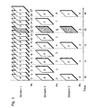
- FIG. 1 is an illustration showing the relations between pictures and picture numbers (PN) when coding an input picture signal (VIN).
- the same picture signal is coded at different picture rates (the number of pictures per second) to make Streams 1, 2 and 3.
- Picture numbers (PN) are numbers to identify coded pictures.
- pictures to be referred to as reference pictures in the following coding are assigned numbers incremented by 1.
- the example of FIG. 1 shows only the case that all pictures in each stream are referred to as reference pictures in the following coding, and the picture numbers are always incremented by 1.
- Pictures that are not referred to in the following coding are unrelated to the increase or decrease in the picture numbers, and not stored in a memory. Therefore, explanation as to pictures that are not referred to in the following coding is omitted because the pictures are unrelated to the following explanation of operations.
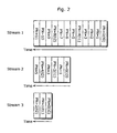
- FIG. 2 is a diagram showing picture numbers (PN) of the pictures to be stored in the reference picture memory when coding or decoding S pictures.
- FIG. 2 shows pictures stored in the reference picture memory (Mem) and their positions.
- the reference picture memory (Mem) pictures in the left position are newer in time than pictures in the right position.
- the same pictures must be referred to in coding and decoding.
- JM2 uses the two methods properly according to purposes.
- the contents of the reference picture memory (Mem) must be the same in every case of switching streams at S pictures.
- the present invention aims at solving all the above-mentioned problems, making the S picture system usable in combination with the other coding method to choose reference pictures in reference picture memory (Mem), and thus providing picture coding and decoding methods that improve compression rates in the above-mentioned combined coding method using S pictures
- XP03005105 and XP03005106 define an Instantaneous Decoder Refresh IDR command for switching pictures.
- a "start of GOP” command is also introduced.
- Picture Numbers (PN) are natural integer numbers used for indexing for-reference-pictures in the reference picture buffer; after an IDR, PN's are re-initialised to "0".
- An IDR picture is a coded picture in which all slices are I or SI slices (INTRA coded picture) that causes the decoding process to mark all reference pictures as "unused for reference” immediately after decoding the IDR picture. After the decoding of an IDR picture, all following coded pictures in decoding order can be decoded, without inter prediction, from any picture decoded prior to the IDR picture.
- the first picture of each coded video sequence is an IDR picture.
- XP 001086627 defines a MMCO "reset" command whereby all pictures in the multi picture reference buffer are marked "unused".
- Document EP 0 982 948 defines a PN reassignment scheme using a feedback mechanism ("continuous- reference-picture-designation-data" is "0" or "1"). PN's are re-encoded using a channel in previous-PN pictures.
- EP 0 940 989 defines a stream switching method for MPEG, after switching, a reference picture may be lost.
- the solution is either a reference picture is repeated or the motion vector is forced to zero in the encoder, or a concealment MV is chosen, or a fading effect is created.
- Picture Numbers PN are not reassigned. There is no memory management considerations.
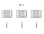
- FIG. 3 is an illustration showing picture numbers (PN) of pictures to be stored in the reference picture memory (Mem). The difference between the same figure and FIG. 2 showing picture numbers (PN) of pictures to be stored in the reference picture memory (Mem) will be explained below.
- FIG. 1 shows the relations of pictures and their picture numbers (PN) when coding input picture signal (Vin), only pictures at the times of to, t1 and t2 that are exactly the same respectively in all streams are stored in the reference picture memory (Mem), while the other pictures are deleted in the reference picture memory (Mem) before coding and decoding S pictures.
- FIG. 3 shows the result of this processing as an illustration showing the picture numbers (PN) of the pictures to be stored in the reference picture memory (Mem).
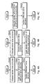
- FIG. 4 is a flow chart showing coding and decoding methods of information concerning picture control of pictures to be stored in the reference picture memory (Mem) in the picture coding decoding methods of the present invention.
- FIG. 4A as a flow chart of the coding method that shows how to realize the method of the operation explained in FIG. 3 , and the coding and decoding methods of the necessary information for realizing the operation.
- Step 1 pictures at the same points of time in a plurality of coding information (streams) are chosen.
- Step 1 it is possible to code delete information showing deletion of the other pictures which are not chosen in Step 0.
- Step 2 pictures which are not chosen in Step 0 are deleted from the reference picture memory (Mem). Up to this point, as shown in FIG. 3 , it is possible to realize the storage condition in the reference picture memory (Mem) to realize decodable streams even after switching coded signals.
- Step 1 and 2 it is possible to change the order of Step 1 and 2, and if it is changed, the flow chart of the picture coding method shown in FIG. 4B is used.
- Decoding the delete information coded according to the coding method shown as the flow chart in FIG. 4A using the decoding method shown as the flow chart in FIG. 4C makes it possible to realize the storage condition of the reference picture memory (Mem) to realize decodable streams using the picture decoding method even after switching coded signals as shown in FIG. 3 .
- Step 6 pictures chosen in Step 5 are deleted in the reference picture memory (Mem). Specifically, when pictures stored in the reference picture memory (Mem) are deleted (or erased), pictures to be deleted are assigned IDs (identification information) such as "release” prohibiting from using the pictures concerned as reference pictures. For that purpose, picture decoding unit (PicDec) and picture encoding unit (PicEnc) always check whether IDs of "release" are assigned or not each time these units refer to pictures stored in the reference picture memory (Mem).
- IDs identification information
- PicDec picture decoding unit
- PicEnc picture encoding unit
- pictures in the reference picture memory (Mem) are deleted (or erased) in the following embodiments.
- this deletion method is an example, it goes without saying that it is possible to delete the above-mentioned picture data in the reference picture memory (Mem) by actually deleting or erasing these data. Up to this point, it is possible to realize the storage condition in the reference picture memory (Mem) to realize decodable streams even after switching the coded signals as shown in FIG. 3 .
- FIG. 5A is an illustration showing picture numbers (PN) of pictures to be stored in the reference picture memory (Mem).
- the difference between FIG. 5A and FIG. 3 showing picture numbers (PN) of pictures to be stored in the reference picture memory (Mem) is whether picture numbers (PN) in the reference picture memory (Mem) are the same or not.
- FIG. 6 is a flow chart showing coding and decoding methods of information for controlling pictures to be stored in the reference picture memory (Mem) according to the picture coding and decoding methods of the present invention, and shows the realization methods of the operation explained in FIG. 5A and the coding and decoding methods of information necessary for the realization.
- Mem reference picture memory
- Step 10 the maximum value of picture numbers (PN) ("8" in the example of FIG. 5A .) of pictures in the coded signals to be switched in the reference memory (Mem) are detected.
- Step 12 information for reassigning picture numbers (PN) of each picture stored in the reference picture memory (Mem) is coded with reference to the maximum value of picture numbers (PN). Also, as the need arises, picture numbers (PN) to be assigned to the next S pictures are coded.
- stream 3 in FIG. 5A is the same as stream 3 in FIG. 3 , there is no need to reassign picture numbers of pictures in stream 3. Therefore, picture numbers are reassigned to necessary pictures only, only information on necessary reassignment needs to be coded in Step 11.
- picture number (PN) of S pictures are 12, in order to make picture numbers (PN) continuous after coding and decoding these S pictures, it is possible to use picture number 11, that is the picture number (PN) immediately before an S picture (immediately before an S picture of stream 1 in FIG. 1 ) as shown in FIG. 5B .
- picture numbers (PN) always increase in the process of coding and decoding as the picture number (PN) of the S picture is 12, which is more effective because the error check function to regard decrease in picture numbers (PN) as an error is also realized.
- FIG. 7 is an illustration showing the relations of pictures and picture numbers (PN) when coding an input picture signal (VIN) of the present invention.
- FIG. 7 is an example of reassignment of picture numbers (PN) using the method explained in FIG. 5B , all the picture numbers of S pictures are 12. Therefore, it is clear that all the pictures after S pictures are correctly decodable even after switching streams at S pictures because pictures in the reference memory (Mem) are identical irrespective of streams when coding and decoding S pictures. Also, it is possible to change the operational order of Step 11 and 12, and in this case, a flow chart of picture coding method shown in FIG. 6B is used.
- Decoding the coded delete information in FIG. 6A shown in the flow chart of the coding method using the decoding method shown in the flow chart in FIG. 6C of the decoding method makes it possible to realize the storage condition of the reference picture memory (Mem) to realize decodable streams using the picture decoding method even after coded signals are switched as shown in FIG. 5A .
- Mem reference picture memory
- Step 15 Decoding the information on reassignment of picture numbers (PN) in Step 15 makes it possible to specify the pictures necessary for reassignment of picture numbers (PN) and the method.
- Step 16 picture numbers (PN) of pictures in the reference picture memory (Mem) is reassigned based on the pictures decoded in Step 15 and also requires for reassignment of picture numbers (PN) and the reassignment method. Up to this point, it is possible to realize the storage condition in the reference picture memory (Mem) to realize decodable streams even after switching the coded signals as shown in FIG. 5 .
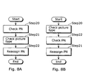
- FIG. 8 is another embodiment so as to realize an illustration of picture numbers (PN) of pictures to be stored in the reference picture memory (Mem) in FIG. 5 .
- Picture types are identified by picture type information (PicType). Therefore, when a picture is identified as an S picture that can change streams by picture type information (PicType), making a rule for reassigning picture numbers (PN) of pictures in the reference picture memory (Mem) to coincide with picture numbers (PN) of S pictures makes it possible to omit coding and decoding the information on reassignment method for each picture number (PN) of pictures in the reference picture memory (Mem).
- Step 20 picture numbers (PN) of pictures are gotten by decoding coded signals.
- the picture type information (PicType) of the pictures is gotten in Step 21.
- picture numbers (PN) of pictures in the reference picture memory (Mem) in a way that they coincide with picture numbers (PN) of S pictures are reassigned based on a specified method in Step 22.
- FIG. 5 it is possible to realize the storage condition in the reference picture memory (Mem) that realizes decodable streams even after switching coded signals.
- Step 21 and 22 it is possible to change the order of Step 21 and 22, and if it is changed, the flow chart of the picture coding method shown in FIG. 8B is used.
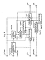
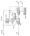
- FIG. 9 is a block diagram showing the structure of the picture coding apparatus of the present invention.
- FIG. 9 as a block diagram concerning the picture coding apparatus of the present invention is an example for realizing the picture coding method in the first embodiment and the second embodiment.
- Picture number generating unit generates picture numbers (PN).
- Picture numbers (PN) are IDs to identify the pictures stored in the reference picture memory (Mem), each picture stored in the reference picture memory (Mem) is assigned to an exclusive picture number (PN).
- PN picture numbers
- PN are incremented by 1 each time a picture is stored in the reference picture memory (Mem).
- Maximum picture number checking unit compares other coded signal picture numbers (OtherPN) and picture numbers (PN) generated in the picture number generating unit (PNGen), detects the maximum value of picture numbers (PN), notifies variable length unit (VLC) and the picture number generating unit (PNGen) of the maximum value of picture numbers (PN), and initializes picture numbers (PN) to be generated in the picture number generating unit (PNGen) using the maximum value of picture numbers (PN).
- Other coded signal picture numbers are picture numbers of pictures in a different stream in parallel with the pictures to be coded. Consequently, after that, the picture number generating unit (PNGen) starts to output picture numbers (PN) larger than the maximum value of the picture numbers (PN).
- TimeCmp Coded picture time comparing unit compares the frame time of each picture in the input picture signal (Vin) coded so far and the frame time of each picture coded as other coded signals (streams), and notifies picture deleting unit (PicDel) of picture information concerning the frame time coded in all the streams.
- picture deleting unit orders reference picture memory (Mem) to delete the pictures outside the time frame in all the streams stored in the reference picture memory (Mem) based on the information notified by the coded picture time comparing unit (TimeCmp), and notifies variable length coding unit (VLC) of the same information at the same time.
- VLC variable length coding unit
- Picture encoding unit (PicEnc) refers to the pictures in the reference picture memory (Mem), codes the input picture signal (Vin) including frequency conversion and quantization as a picture type showin in the picture type information (PicType), sends the result to picture decoding unit (PicDec) and variable length coding unit (VLC).
- Picture decoding unit (PicDec) performs inverse quantization and frequency conversion of the coding result in picture encoding unit (PicEnc) as picture types shown in the picture type information (PicType), and stores the picture types as picture numbers (PN) in the reference picture memory (Mem) so as to refer to the picture types in the following picture coding process.
- Variable length coding unit makes the coded result in picture encoding unit (PicEnc) into variable length codes so as to make a bit stream, codes the information needed for decoding, that is the information for deleting pictures stored in the reference picture memory (Mem) notified by the picture deleting unit (PicDel), the maximum value of the picture numbers (PN) and picture numbers (PN) mentioned above so as to output the information as coded signals (Str).
- Variable length coding unit (VLC) also codes information notified by picture deleting unit (PicDel) and information for reassigning picture numbers (PN) of pictures stored in the reference picture memory (Mem) based on the method shown in the second embodiment.
- FIG. 10 shows a structural example of coded signals (Str) in the present invention. Each data in FIG. 10A will be explained below.
- picture numbers are coded.
- the maximum picture number (PN) to be reassigned, information for deleting pictures stored in the reference picture memory (Mem) and information for reassigning picture numbers stored in the reference picture memory (Mem) are coded.
- picture type information (PicType) and picture coded data which is outputted by picture encoding unit (PicEnc) are located.
- FIG. 10A is simply an example of data location, it is possible to change order of data as shown in FIG. 10B so as to perform picture coding.
- the picture coding apparatus consists of the above-mentioned units that realizes the picture coding method shown in the first and the second embodiments.
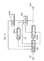
- FIG. 11 is a block diagram showing the structure of the picture decoding apparatus of the present invention.
- FIG. 11 as a block diagram concerning the picture decoding apparatus of the present invention is an example of a picture decoding apparatus that realizes the first, the second and the third embodiments. Its function will be explained below.
- VLD Variable length decoding unit decodes coded signals (Str), outputs various information (such as an order for deleting pictures stored in the reference picture memory (Mem), picture type information (PicType), picture numbers (PN), information for reassigning picture numbers (PN) and picture data.)
- the order for deleting pictures stored in the reference picture memory (Mem) gotten in variable length decoding unit (VLD) is firstly sent to picture deleting unit (PicDel).
- Picture deleting unit (PicDel) deletes the specified pictures stored in the reference picture memory (Mem).
- Picture type information (PicType) gotten in the variable length decoding unit (VLD) is sent to picture decoding unit (PicDec) so as to show the decoding method.
- Picture numbers (PN) gotten in variable length decoding unit (VLD) is sent to the reference picture memory (Mem) as picture numbers (PN) when storing the pictures decoded in picture decoding unit (PicDec).
- Picture number changing unit (PNchg) follows the directions and reassign picture numbers (PN) of pictures stored in the reference picture memory (Mem). To be more specific, picture number changing unit (PNchg) reads out picture numbers (PN) of pictures stored in the reference picture memory (Mem), reassigns the values of picture numbers (PN) read out, and then writes the new picture numbers (PN) in the reference picture memory (Mem).
- picture decoding unit PicDec
- picture data gotten in variable length decoding unit VLD
- a suitable decoding method for the specified picture type shown as picture type information (PicType) PicType
- I pictures are decoded without referring pictures in the reference picture memory (Mem) while P pictures and B pictures are decoded by referring to pictures in the reference picture memory (Mem).
- the decoded pictures gotten in this way are stored in the reference picture memory (Mem) and outputted as decoded picture signals (Vout).
- the picture decoding apparatus consists of the above-mentioned units that realizes the picture decoding method shown in the first, the second, and the third embodiments.
- the picture numbers of the pictures before the switchable pictures are switched so as to make the picture numbers continuous with the picture numbers of the switchable pictures.
- picture numbers are switched at the switchable pictures.
- coding of a plurality of streams having a different picture rate or a bit rate, or a different structure here is an example of a stream switching method that enables coding after switching coded pictures from a picture under coding in a stream to a picture in another stream.
- switching streams For convenience of explanation, the simpler phrase of "switching streams" is used below.
- whether pictures to be coded should be stored in the reference memory or not is judged based on the increment in picture number between pictures to be coded and pictures forwardly adjacent to the pictures to be coded (Simply, "the preceding picture” is used below.) in coding order.
- an increment in picture number between a preceding picture and a picture to be coded is 1, which means the pictures to be coded is stored in the reference memory.
- the picture number of the pictures to be coded is the same as the picture number of the preceding pictures, which means the current picture is not stored in the reference memory.
- FIG. 12 is a diagram showing an example of the relations between pictures and picture numbers (PN) when an input picture number (Vin) is coded.
- An identical picture signal is coded at different picture rates to make streams of 1, 2 and 3.
- pictures are located according to the cording order in each stream.
- picture numbers (PN) are assigned to each picture so that the picture numbers are incremented by 1. Also, in stream 2, there are pictures assigned picture numbers (PN) incremented by 1 and pictures assigned the same picture numbers (PN) as the precedent pictures. Also, in stream 3, picture number (PN) are assigned to each picture so that the picture numbers are incremented by 1 like in stream 1.
- pictures to be coded are stored in the reference memory.
- pictures assigned picture numbers (PN) in a way that the picture numbers are incremented by 1 are stored in the reference memory, and pictures assigned the same picture numbers (PN) as the precedent pictures are not stored in the reference memory.
- pictures assigned the picture number of "0" in streams of 1, 2 and 3 are pictures to be displayed at the time of t0.
- the groups of pictures listed below are pictures to be displayed at the same time: Picture F14 in stream 1, picture F22 in stream 2 and picture F31 in stream 3 are pictures to be displayed at the time of t1.
- Picture F18 in stream 1, picture F24 in stream 2 and picture F32 in stream 3 are pictures to be displayed at the time of t2.
- Picture F112 in stream 1, picture F26 in stream 2 and picture F33 in stream 3 are pictures to be displayed at the time of t3.
- Picture F117 in stream 1, picture F215 in stream 2 and picture F34 in stream 3 are pictures to be displayed at the time of t4. Note that pictures F112, F26 and F33 correspond to S pictures in the first and second embodiments.
- streams are switched by way of picture BP1 and BP2 that exist between the picture before switching and the picture after switching, and both of the BP1 and the BP2 are switching pictures to be coded in a way that they have the same time as their precedent pictures in the respective switching streams.
- switching picture BP1 that exists between F26 and F113 is used as a picture at the time of t3.
- the picture number of switching picture BP1 which is a switching pictureis changed to "12" to make the number continuous with the picture number 13 of picture F113 in the stream after switching.
- switching picture BP2 that exists between F32 and F213 is used as a picture at the time of t3.
- the picture number of switching picture BP2 which is a switching picture is changed to make the number continuous with the picture number 13 of picture F213 in the stream after switching.
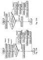
- FIG. 13 is a flow chart showing a coding method after assigning picture numbers (PN) to respective pictures in the streams in FIG. 12 .
- PN picture numbers
- step 1401 whether each of the pictures to be coded is S picture or not is judged.
- picture numbers (PN) of the current pictures are changed to the initial values of M in step 1402.
- picture numbers (PN) of the current pictures are not changed.
- step 1403 whether each of the pictures to be coded is the next pictures of S pictures or not is judged.
- step 1404 whether each of S pictures is stored in the memory or not is judged in step 1404.
- step 1405 When the current pictures are not the next pictures of S pictures, whether each of the current pictures is stored in the memory or not is judged in step 1405.
- step 1404 When S pictures are not judged to be stored in the memory in step 1404, the picture numbers (PN) are regarded as "M"s in step 1407. The picture numbers (PN) are not changed. In step 1405, whether the pictures to be coded are stored in the memory or not is judged. When the current pictures are judged to be stored in the memory, the picture numbers (PN) are incremented to PN+1 in step 1408, and the incremented picture numbers (PN) replace the old picture numbers (PN).
- step 1409 target pictures are coded.
- step 1410 whether all the current pictures have been coded or not is judged. When all the current pictures have not been coded, step 1401 must be repeated. When all the current pictures have been coded, step 1410 finishes.
- the processing shown in FIG. 13 makes it possible to produce coded data streams whose picture numbers (PN) are continuous in the streams after switching coded pictures.
- the coded signals (Str) produced in this way can be decoded based on the decoding method by the picture decoding apparatus in the fifth embodiment. In this way, the picture decoding apparatus that decodes coded signals in the sixth embodiment is realized.
- the coding and the decoding methods shown in the above-mentioned first to sixth embodiments can be implemented in mobile communication instruments such as cellular phones and car navigation systems and cameras such as digital video cameras or digital steel cameras by using semiconductors such as LSI.
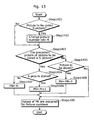
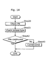
- FIG. 14 shows the processing of checking and correcting errors of picture numbers (PN) based on picture numbers (PN).
- picture numbers (PN) are detected in step 20.
- picture types (PicType) are detected in step 21.
- whether picture numbers (PN) detected in step A2 are continuous or not is judged.
- the picture numbers (PN) are continuous in step A2, error checking and correcting processing of picture numbers (PN) is completed.
- the picture numbers (PN) are not continuous in step A2, errors must be corrected in step A3. Note that the processing of checking the stored maximum PN and reassigning "PN"s can be performed either way of solely done after this error checking and correcting processing or concurrently done with this error checking and correcting processing.
- the first conceivable method of error correcting processing in step A3 is requesting for resending the data concerning the picture numbers with errors and following the error checking processing of picture numbers (PN) again after receiving the resent data.
- the cause of the discontinuity in picture numbers (PN) of S pictures is not a transmission error. That is, as the number of pictures in each stream stored in the memory prior to the S pictures may vary in the case where the discontinuity in picture numbers (PN) of S pictures is found, the picture whose picture number (PN) is required for being resent may not exist, and thus it is highly unlikely that a missing picture can be sent. Therefore, the requests for the pictures that cannot be sent are made endlessly, which may be a hindrance in displaying pictures. For this reason, as to countermeasures in the case of trouble in displaying pictures, further explanation will be made in a tenth embodiment below.
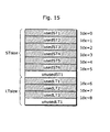
- the memory for short-time storage can store 7 pictures
- the memory for long-time storage can store 4 pictures
- reference picture are specified based on the order calculated from the memory for short-time storage.
- the locations in the memory to specify the identical pictures vary from stream to stream as shown in FIG. 2 .
- the locations in the memory to specify reference pictures vary according to the memory in each stream.
- I pictures can be the pictures at which streams are switched when the pictures decoded in a plurality of streams in the reference memory are exactly the same, and thus I pictures can be used for the same purpose as S pictures (for switching streams).
- this seventh embodiment will show the coding and decoding methods of additional information used for avoiding an endless error checking processing of picture numbers (PN) triggered by problems like discontinuity of picture numbers (PN) or incongruity in the content of the memory.
- This additional information (all picture delete information) is the order for showing that pictures except I pictures and S pictures to be coded must be deleted from the memory for reference in coding and decoding in order to prevent any error from occurring in the process of coding pictures after coding I pictures capable of intra-picture coding and the above-mentioned S pictures.
- This process makes each memory condition identical in a plurality of streams after switching streams from a predetermined stream to another stream and makes it possible to specify predetermined pictures in the memory correctly even when reference pictures are needed for intra-predictive coding and so on. Also, preventing discontinuity in picture numbers (PN) from being detected and corrected as an error resolves the problem of hindering decoding caused by requests for resending nonexistent pictures.
- PN picture numbers
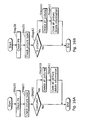
- FIG. 16A shows the making processing of coded signals in this seventh embodiment.
- picture numbers are detected in step 20.
- picture types are detected in step 21. Whether the picture types detected are I pictures or not is judged in step A1.
- the picture types detected are I pictures, all the pictures except I pictures to be coded in the memory are deleted in step A10.
- all picture delete information meaning deleting all the pictures in the memory is coded, and this is the last procedure of coding additional information.
- step A1 in FIG. 16A can be used as a step for judging whether the picture types are S pictures or not in the same coding processing as shown in FIG. 16B . Also, it is possible to combine step A1 with step A2 and judge whether the picture types are I pictures or S pictures after checking the picture types in step 21.
- step A1 when the picture types to be coded are proved to be I pictures in step A1 at the time of checking the picture types in step 21 and when the picture numbers (PN) are judged to be discontinuous after the judgment on whether the picture numbers are continuous or not like the judgment made in step A3, it is also possible to delete all the pictures except I pictures to be coded in the memory. On the other hand, when picture numbers (PN) are continuous in step A3, the pictures in the memory are not deleted.
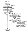
- FIG. 17A When checking S pictures as picture types, the same explanation shown in FIG. 17A holds true. Also, it is possible to combine step A1 with step A2 and judge whether the picture types are I pictures or S pictures after checking the picture types in step 21.
- step 30 It is also possible to perform the processing of step 30 judging whether the numbers of pictures stored in the memory are the same or not so as to avoid the occurrence of errors caused by the difference in the number of pictures stored in the memory as shown in FIG. 17B after the processing of step A3 shown in FIG. 17A . It is possible to perform the processing of step A30 before going on to the processing of step A3 shown in FIG. 17 . And it is possible to delete all the pictures after performing Step A30 before performing Step A3 in FIG. 17B when the numbers of pictures vary from stream to stream, and it is possible to delete all the pictures shown in step A10 when the numbers of pictures do not vary from stream to stream and the picture numbers (PN) are discontinuous. ( FIG. 18 )
- FIG. 17 makes it possible to keep storing the pictures that may be reference pictures in the memory as many as possible and improve the reproducibility of pictures decreasing errors.
- I pictures or S pictures they need no error correction when the numbers of pictures stored in the memory vary or the picture numbers (PN) are discontinuous, which simplifies memory control in the coding apparatus.
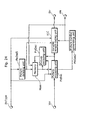
- FIG. 19 is a block diagram showing the structure of the picture coding apparatus of the present invention.
- the block diagram of the picture coding apparatus in the present invention shown in FIG. 19 is an example for realizing the picture coding method in FIG. 16 .
- Picture number generating unit generates picture numbers (PN).
- Picture numbers (PN) are IDs that identify pictures stored in the reference picture memory (Mem), and each different picture stored in the reference picture memory (Mem) is given an exclusive picture number (PN).
- PN picture numbers
- picture numbers (PN) are incremented by 1 each time a picture is stored in the reference picture memory. If picture numbers (PN) received in the picture decoding apparatus are incremented by 2 or more, it is possible to detect the lack of pictures to be stored in the transmission line by the picture decoding apparatus and carry out error correction processing such as picture improvement (making the error less conspicuous) or error correction (retransmitting the picture with no errors to reproduce the picture).
- picture deleting unit 3 orders the reference picture memory (Mem) to delete the pictures stored in the reference picture memory (Mem) except pictures to be coded, and sends the information to variable length coding unit (VLC) at the same time.
- the picture type information shows that the pictures concerned are I pictures (corresponding to the processing of step A1 in FIG. 16 ), picture deleting unit (PicDel) orders the reference picture memory (Mem) to delete the pictures stored in the reference picture memory (Mem) except pictures to be coded, and also sends the information to variable length coding unit (VLC) at the same time.
- picture deleting unit PicDel
- VLC variable length coding unit
- Picture encoding unit refers to the pictures stored in the reference picture memory (Mem) so as to code the input picture signal (Vin) including frequency conversion and quantization as picture types shown by picture type information (PicType) and send the result to the picture decoding unit (PicDec) or the variable length coding unit (VLC).
- Picture decoding unit (PicDec) inversely quantizes and converts the frequency of the information coded in the picture encoding unit (PicEnc) as picture types shown as picture type information (PicType), and stores the information in the reference picture memory (Mem) as picture numbers (PN) to refer so as to the picture numbers in the following picture coding.
- VLC Variable length coding unit
- PicEnc picture encoding unit
- PicDel picture deleting unit 3
- PN picture numbers
- PicType picture type information
- Picture numbers are coded.
- information for deleting pictures stored in the reference picture memory (Mem)
- picture type information (PicTypz)
- picture coding data outputted by the in picture encoding unit (PicEnc) are located.
- FIG. 10C is merely an example of data location, it is possible to switch data coding orders as shown in FIG. 10D .
- the above-mentioned processing enables the picture coding apparatus to realize the picture coding method shown in FIG. 16 and provide a coding apparatus with high error-resistance.
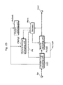
- FIG. 20 is a block diagram showing the structure of the picture coding apparatus in the present invention.
- the block diagram of the picture coding apparatus of the present invention shown in FIG. 20 is an example for realizing the picture coding method in FIG. 17 . Explanation concerning the same units as explained in FIG. 19 will be omitted from the following explanations.
- FIG. 20 and FIG. 19 differ in the process in picture deleting unit 4 (PicDel).
- picture deleting unit 4 PicDel
- picture deleting unit 4 orders the reference picture memory (Mem) to delete the pictures stored in the reference picture memory (Mem) except pictures to be coded, and sends the information to variable length coding unit (VLC) at the same time.
- VLC variable length coding unit
- the above-mentioned processing enables the picture coding apparatus to realize the picture coding method shown in FIG. 17 and provide the coding apparatus with high error-resistance.
- the seventh embodiment above showed that picture display may be hindered because requests for resending pictures that cannot be resent are repeatedly made when discontinuity of picture numbers occurred at an S picture.
- the problem-solving method for the example of picture display with troubles caused by this reason will be explained below.
- FIG. 21A shows the processing of decoding the coded pictures.
- picture numbers (PN) are detected in step 20.
- picture types (PicType) are detected in step 21. Whether the picture types detected are I pictures or not is judged in step A1. When the picture types detected are not I pictures, whether the picture numbers (PN) are continuous or not is judged in step A3. On the other hand, when the picture types detected are I pictures, there is no need to detect or correct errors and a series of processing finishes.
- step A3 When the picture numbers (PN) are not continuous in step A3, errors are corrected in step A4. On the other hand, the picture numbers (PN) are continuous in step A3, error check and correction are completed.
- Error correction in step A4 can be, for example, processing of detecting the stored maximum picture numbers (PN) as explained in the above-mentioned embodiment, or deleting all the pictures in the memory after receiving all picture delete information meaning deleting all the pictures in the memory in the processing of reassigning picture numbers (PN).
- PN stored maximum picture numbers
- step A1 in FIG. 21A the same coding processing can be performed as a step of judging whether the picture types are S pictures or not. Also, it is possible to combine step A1 with step A2 and judge which picture types of I pictures or S pictures they have after checking the picture types in step 21.
- FIG. 22 is a block diagram showing the structure of the picture decoding apparatus of the present invention.
- the block diagram of picture decoding apparatus of the present invention shown in FIG. 22 shows an example for realizing the picture decoding method shown in FIG. 21 . Explanation concerning the same units as explained in FIG. 11 will be omitted from the following explanations.
- the different point of FIG. 22 from FIG. 11 is the processing in the error checking unit (ErrChk) using picture types (PicType) by the picture number checking unit (PNchk).
- PicType picture number checking unit
- an error correction order Err
- processing such as the stored maximum PN check, PN reassignment or deleting all the pictures in the memory according to all picture delete information meaning deleting all the pictures in the memory.
- the above-mentioned processing enables the picture coding apparatus to realize the picture coding method shown in FIG. 21 and provide a decoding apparatus with high error-resistance.
- This embodiment explains another countermeasure against an endless error check of picture numbers (PN) caused by the troubles such as discontinuity of picture numbers (PN) or incongruity in memory contents.
- This twelfth embodiment differs from the seventh embodiment in that the picture numbers (PN) are reassigned from "0" when all the pictures are deleted after the same step of deleting all the pictures in coding shown in the seventh embodiment.
- This process makes the respective memory conditions in a plurality of streams identical after switching streams from a predetermined stream to another stream, and initializes the picture numbers (PN), and thus it makes it possible to correctly specify the predetermined pictures in the memory even when reference pictures are required in intra-predictive coding and so on. It is also possible to resolve the problem of hindering decoding when switching the coded streams to be decoded from the predetermined stream to another stream by avoiding correcting any picture number discontinuity as errors.
- PN picture numbers
- each picture in the stream is given an exclusive picture number (PN) continuous in display time order in the coded streams gotten by coding moving pictures.
- PN exclusive picture number
- the reason why the picture numbers (PN) are given exclusive picture numbers (PN) continuous in display time order is that it makes it possible to check the lack of pictures in the coded streams caused by an error in transmission line in the case where the picture decoding apparatus receives the coded streams by way of the transmission line.
- PN picture number of a picture to be inputted in display time order is incremented by 2 or more while the received coded stream is being decoded
- this picture decoding apparatus can check the transmission error occurred just before the receiving time of the picture concerned and request the sender to resend the missing pictures. Therefore, as long as the picture decoding apparatus is decoding one coded stream continuously, it can check transmission errors effectively and receive the resent missing pictures to decode the coded streams perfectly.
- this error check causes a glitch of endless error checking processing, in the case of the picture decoding apparatus used for continuing decoding after switching to another coded stream with a different picture rate while decoding a coded stream after inputting a plurality of coded streams gotten by coding the same moving picture at a different picture rate.
- the cause of this glitch is that picture numbers (PN) of pictures except the first picture in each stream vary among coded pictures with different picture rates even in the case of the pictures to be displayed at the same time, in other words, picture numbers (PN) are continuous within each coded stream in the display time order.
- picture numbers (PN) are discontinuous even in the case of the pictures to be displayed at the same time.
- the coding method using additional information has been explained in the seventh embodiment so as to avoid the endless error check of picture numbers (PN) caused by the problems such as discontinuity of picture numbers (PN) or incongruity of memory contents in this way.
- This additional information is the order for deleting all the pictures except pictures to be coded from the memory for reference in coding or decoding so that any error should not occur at the time of switching streams in the process of picture coding after coding I pictures for intra-coding or the above-mentioned S pictures.
- FIG. 23A shows the making processing of coded signals in this twelfth embodiment.
- picture numbers (PN) are detected in step 1.
- picture numbers (PN) detected in step 1 are coded in step 2.
- picture types (PicType) are detected in step 3. In the step 3, whether the detected picture types are S pictures or not is judged.
- step 5 When the detected picture types are S pictures, all picture delete information meaning deleting all the pictures in the memory is coded in step 5.
- S pictures are coded in step 6A.
- picture numbers are initialized in step 7, and in the following step 8, all the pictures except S pictures to be coded in the memory are deleted in step 8. Up to this point, the processing of coding additional information and initializing picture numbers (PN) finishes.
- PN picture numbers
- S pictures As picture numbers (PN) are continuous unless the detected picture types are S pictures, these pictures are coded in step 6B, but the processing is completed without coding additional information, initializing picture numbers (PN), and deleting all the pictures.
- Initialization of picture numbers (PN) in step 7 is such as giving picture number of "0" to the coded S pictures.
- initializing picture numbers (PN) of S pictures means giving the pictures after S pictures in display time order new picture numbers (for example, PN 1) starting from the picture number (PN 0) of S pictures. Consequently, picture numbers (PN) are initialized after coding S pictures (that is, after coding the picture numbers (PN) of S pictures.).
- step 4 The judgment on whether the pictures are S pictures or not is made in step 4, the judgment on whether the pictures are I picturesare I pictures or not can be made. Also, when there is a step of deleting all the pictures in step 23A, picture numbers (PN) should be initialized concurrently because whether the pictures are I pictures or S pictures or not is not a sole judgmental standard as to whether picture numbers (PN) should be initialized. Also, picture number (PN) coding processing in Step 2 can be performed at any time between picture number checking processing in step 1 and the picture number initializing processing in step 7. Also, it is possible to initialize picture numbers (PN) in step 7 after deleting all the pictures except S pictures to be coded in the memory in step 8.
- the processing of coding all picture delete information meaning deleting all the pictures in the memory in step 5 is the processing after the judgment whether the pictures are S pictures or not and can be performed at any time before the processing shown in FIG. 23A is finished. Also, it is possible not to code additional information by using special picture types (PicType) that include additional information meaning deleting all the pictures except the pictures to be coded from the memory for reference in coding or decoding.
- PicType special picture types
- PN picture numbers
- FIG. 24 is a block diagram showing the structure of the picture coding apparatus capable of realizing the coding method in the twelfth embodiment.
- Picture number generating unit generates Picture numbers (PN).
- Picture numbers (PN) are IDs that identify the pictures stored in the reference picture memory (Mem), each picture stored in the reference picture memory (Mem) is given an exclusive picture number (PN). Basically, picture numbers (PN) are incremented by 1 each time a picture is stored in the reference picture memory (Mem). Also, picture numbers (PN) of the current S pictures are initialized to "0" after S pictures are coded according to the notification from picture encoding unit (PicEnc).
- picture deleting unit 5 PicDel
- picture deleting unit 5 notifies the reference picture memory (Mem) of an order of deleting the pictures except the pictures to be coded (all picture delete information) stored in the reference picture (Mem) memory and notifies the variable length coding unit (VLC) of the information at the same time.
- the picture encoding unit (PicEnc) refers to the pictures stored in the reference picture memory (Mem) so as to code the input picture signal (Vin) into picture types shown by picture type information (PicType) concurrently performing frequency conversion and quantization and send the result to the picture decoding unit (PicDec) and the variable length coding unit (VLC). Also, the picture encoding unit (PicEnc) notifies the picture number generating unit 2 (PNGen) of the order of initializing picture numbers (PN) after coding S pictures.
- PNGen picture number generating unit 2
- the picture decoding unit (PicDec) inversely quantizes and inversely converts the information coded in the picture encoding unit (PicEnc) into picture types shown as picture type information (PicType), and stores the information in the reference picture memory (Mem) associating with picture numbers (PN) so as to refer to the picture types in the following picture coding.
- variable length coding unit performs variable length coding on the information coded in picture encoding unit (PicEnc) so as to make a bit stream, and codes necessary information in decoding such as the information for deleting pictures stored in the reference picture memory (Mem) (that is, all picture delete information) notified by picture deleting unit 5 (PicDel), picture numbers (PN), and picture type information (PicType) to output the information as coded signals (Str).
- FIG. 23B shows the decoding processing of coded signals.
- step 9 picture numbers (PN) are decoded in step 9. Next, whether all picture delete information is coded or not is judged in step 10.
- step 10 When all picture delete information is judged to be coded in step 10, all picture delete information is decoded in step 11. And, pictures are decoded in step 12A. After that, all the pictures except the pictures to be decoded in the memory are deleted in step 13, and picture numbers (PN) are initialized in step 14. Up to this point, the processing of decoding additional information and initialization of picture numbers (PN) finishes.
- step 12B When all picture delete information is judged not to be coded in step 10, pictures are decoded in step 12B, and the processing of decoding additional information and initializing picture numbers (PN) is completed in step 12B.
- PN initializing picture numbers
- Initialization of picture numbers (PN) in step 14 is such as giving picture number of "0" to the decoded pictures.
- initializing picture numbers (PN) of S pictures means giving the pictures after S pictures in display time order new continuous picture numbers starting from the picture number of S pictures.
- the processing of initializing picture numbers (PN) is necessary, in other words, the judgment on whether the picture numbers should be initialized is not influenced by picture types to be decoded.
- the processing of initializing picture numbers (PN) in step 14 can be performed before the processing of deleting all the pictures except the pictures to be coded in the memory in step 13. It is possible not to code additional information by using special picture types (PicType) that include additional information meaning deleting all the pictures except the pictures to be decoded from the memory for reference in decoding.
- PicType special picture types
- FIG. 25 is a block diagram showing the structure of the picture decoding apparatus that realizes the decoding method of this twelfth embodiment.
- VLD Variable length decoding unit decodes coded signals (Str), and outputs various information (such as an order for deleting the pictures stored in the reference picture memory (Mem), picture type information (PicType), picture numbers (PN), information for reassigning picture numbers (PN), and picture data.)
- Picture type information (PicType) gotten in variable length decoding unit (VLD) is sent to picture decoding unit (PicDec) to specify the decoding method.
- Picture numbers (PN) gotten in variable length decoding unit (VLD) is sent to the reference picture memory (Mem) to be used as picture numbers (PN) at the time of storing the pictures decoded in the picture decoding unit (PicDec).
- Picture number changing unit 2 (PNchg) reassigns (initializes) picture numbers (PN) of the pictures stored in the reference picture memory (Mem) according to the order.
- picture number changing unit 2 (PNchg) reads out the picture numbers (PN) of the pictures stored in the reference picture memory (Mem), changes the values of the read-out picture numbers (PN) to "0", and writes the picture numbers (PN) in the reference picture memory (Mem).
- VLD variable length decoding unit
- P pictures and B pictures are decoded referring to the pictures stored in the reference picture memory (Mem) while I pictures are decoded without referring to pictures in the reference picture memory.
- the decoded picture gotten in this way are stored in the reference picture memory (Mem) and outputted as decoded picture signals (Vout).
- the above-mentioned structure makes it possible to realize the picture decoding apparatus to realize the picture decoding method shown in FIG. 23 and provide a decoding apparatus with high error-resistance.
- the processing of the coding and the decoding methods shown in this twelfth embodiment makes the memory conditions in a plurality of streams identical after switching streams from a predetermined stream to another stream, and thus makes it possible to correctly specify the predetermined pictures in the memory even when reference pictures are required in intra-predictive coding and so on.
- IDR picture is effective as a leading I picture of Group of Pictures (GOP) because IDR pictures become a starting position of random access.
- PN picture numbers
- the picture decoding apparatus detects IDR pictures in the coded streams based on picture types, deletes all the pictures except the current IDR pictures in the memory, and initializes picture numbers (PN) after coding and decoding the current IDR pictures even when any additional information is not coded each time IDR pictures are decoded.
- PN picture numbers
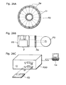
- FIG. 26 is an illustration concerning the storage medium to store the program to realize the coding and the decoding methods shown in the first to the twelfth embodiments mentioned above in the computer systems.
- FIG. 26B shows a flexible disc and the front view and the cross-sectional view of the appearance of the flexible disc
- FIG. 26A shows an example of a physical format of a flexible disc as a recording medium body.
- a flexible disc (FD) is contained in a case F, a plurality of tracks (Tr) are formed concentrically on the surface of the disc from the periphery into the inner radius of the disc, and each track is divided into 16 sectors (Se) in the angular direction. Therefore, in the case of the flexible disc storing the above-mentioned program, the picture coding method and the picture decoding method as the program is recorded in an area allocated for it on the flexible disc (FD).
- FIG. 26C shows the structure for recording and reading out the program on the flexible disc (FD).
- the computer system (Cs) When the program is recorded on the flexible disc (FD), the computer system (Cs) writes in the picture coding method or the picture decoding method as a program via a flexible disc drive.
- the picture coding method and the decoding method mentioned above are constructed in the computer system by the program on the flexible disc, the program is read out from the flexible disc drive and transferred to the computer system.
- the above explanation is made using a flexible disc as a recording medium, but the same processing can also be performed using an optical disc.
- the recording medium is not limited to flexible discs and optical discs, in other words, any other medium capable of recording a program such as DC-ROMs, memory cards, and ROM cassettes can be used.
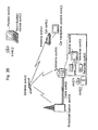
- FIG. 27 is a block diagram showing the overall configuration of a content supply system ex100 for realizing content distribution service.
- the area for providing communication service is divided into cells of desired sizes, and cell sites ex107 ⁇ ex110 of fixed wireless stations are placed in the respective cells.
- This content supply system ex100 is connected to apparatuss such as a computer ex111, a Personal Digital Assistant (PDA) ex112, a camera ex113, a cell phone ex114 and a cell phone with a camera ex115 via, for example, a combination of the Internet ex101, an Internet service provider ex102, a telephone network ex104 and cell sites ex107 ⁇ ex110.
- PDA Personal Digital Assistant
- the content supply system ex100 is not limited to the configuration as shown in FIG. 27 , and may be connected to a combination of any of them. Also, each apparatus can be connected directly to the telephone network ex104, not through the cell sites as fixed radio stations ex107 ⁇ ex110.
- the camera ex113 is a apparatus capable of shooting video (moving pictures) such as a digital video camera.
- the cell phone can be a cell phone of a Personal Digital Communication (PDC) system, a Code Division Multiple Access (CDMA) system, a Wideband-Code Division Multiple Access (W-CDMA) system or a Global System for Mobile Communications (GSM) system, a Personal Handy-phone system (PHS) or the like.
- PDC Personal Digital Communication
- CDMA Code Division Multiple Access
- W-CDMA Wideband-Code Division Multiple Access
- GSM Global System for Mobile Communications
- PHS Personal Handy-phone system
- a streaming server ex103 is connected to the camera ex113 via the telephone network ex104 and the cell site ex109, which enables live distribution or the like using the camera ex113 based on the coded data transmitted from the user.
- Either the camera ex113 or the server for transmitting the data can code the shot data.
- the moving picture data shot by a camera ex116 can be transmitted to the streaming server ex103 via the computer ex111.
- the camera ex116 is a apparatus capable of shooting still and moving pictures such as a digital camera.
- Either the camera ex116 or the computer ex111 can code the moving picture data.
- An LSI ex117 included in the computer ex111 or the camera ex116 performs coding processing.
- Software for coding and decoding pictures can be integrated into any type of storage media such as CD-ROMs, flexible discs and hard discs) that is a recording medium which is readable by the computer ex111 or the like. Furthermore, a cell phone with a camera ex115 can transmit the moving picture data. This moving picture data is the data coded by the LSI included in the cell phone ex115.
- the contents supply system ex100 codes contents (such as a music live video) shot by users using the camera ex113, the camera ex116 or the like in the same manner as the above-mentioned embodiments and transmits them to the streaming server ex103, while the streaming server ex103 makes stream distribution of the contents data to the clients upon their request.
- the clients include the computer ex111, the PDA ex112, the camera ex113, the cell phone ex114 and so on that are capable of decoding the above-mentioned coded data.
- the clients can thus receive and reproduce the coded data, and further can receive, decode and reproduce the data in real time so as to realize personal broadcasting in this way.
- the picture coding apparatus or the picture decoding apparatus can be used, as shown in the above-mentioned embodiments.
- a cell phone will be explained as an example of the apparatus.
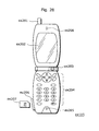
- FIG. 28 is a diagram showing the cell phone ex115 using the picture coding method and the picture decoding method explained in the above-mentioned embodiments.
- the cell phone ex115 has an antenna ex201 for communicating with the cell site ex110 via radio waves, a camera unit ex203 capable of shooting moving and still pictures such as a CCD camera, a display unit ex202 such as a liquid crystal display for displaying the data obtained by decoding pictures and the like shot by the camera unit ex203 and received by the antenna ex201, a body unit including a set of operation keys ex204, a voice output unit ex208 such as a speaker for outputting voices, a voice input unit 205 such as a microphone for inputting voices, a storage medium ex207 for storing coded or decoded data such as data of moving or still pictures shot by the camera, data of received e-mail and data of moving or still pictures, and a slot unit ex206 for attaching the storage medium ex207 to the cell phone ex115.
- a camera unit ex203 capable of shooting moving and still pictures such as
- the storage medium ex207 is equipped with a flash memory element, a kind of Electrically Erasable and Programmable Read Only Memory (EEPROM) that is an electrically erasable and rewritable nonvolatile memory, in a plastic case such as SD cards.
- EEPROM Electrically Erasable and Programmable Read Only Memory
- a main control unit ex311 for overall controlling each unit of the body unit including the display unit ex202 and operation keys ex204 is connected to a power supply circuit unit ex310, an operation input control unit ex304, a picture coding unit ex312, a camera interface unit ex303, an Liquid Crystal Display (LCD) control unit ex302, a picture decoding unit ex309, a demultiplexing unit ex308, a recording and reproducing unit ex307, a modem circuit unit ex306 and a voice processing unit ex305 to each other via a synchronous bus ex313.
- LCD Liquid Crystal Display
- the power supply circuit unit ex310 supplies respective components with power from a battery pack so as to activate the digital cell phone with a camera ex115 for making it into a ready state.
- the voice processing unit ex305 converts the voice signals received by the voice input unit ex205 in conversation mode into digital voice data under the control of the main control unit ex311 including a CPU, a ROM and a RAM, the modem circuit unit ex306 performs spread spectrum processing of the digital voice data, and the communication circuit unit ex301 performs digital-to-analog conversion and frequency transform of the data so as to transmit it via the antenna ex201.
- the communication circuit unit ex301 amplifies the data received by the antenna ex201 in conversation mode and performs frequency transform and analog-to-digital conversion for the data, the modem circuit unit ex306 performs inverse spread spectrum processing of the data, and the voice processing unit ex305 converts it into analog voice data so as to output it via the voice output unit 208.
- the text data of the e-mail inputted by operating the operation keys ex204 on the body unit is sent out to the main control unit ex311 via the operation input control unit ex304.
- the modem circuit unit ex306 performs spread spectrum processing of the text data
- the communication circuit unit ex301 performs digital-to-analog conversion and frequency transform for it
- the data is transmitted to the cell site ex110 via the antenna ex201.
- the moving picture data shot by the camera unit ex203 is supplied to the picture coding unit ex312 via the camera interface unit ex303.
- the picture data is not transmitted, it is also possible to display the picture data shot by the camera unit ex203 directly on the display unit 202 via the camera interface unit ex303 and the LCD control unit ex302.
- the picture coding unit ex312 which includes the picture coding apparatus as explained in the present invention, compresses and codes the picture data supplied from the camera unit ex203 using the coding method used for the picture coding apparatus as shown in the above-mentioned embodiments so as to transform it into coded picture data, and sends it out to the demultiplexing unit ex308.
- the cell phone ex115 sends out the voices received by the voice input unit ex205 during shooting by the camera unit ex203 to the demultiplexing unit ex308 as digital voice data via the voice processing unit ex305.
- the demultiplexing unit ex308 multiplexes the coded picture data supplied from the picture coding unit ex312 and the voice data supplied from the voice processing unit ex305 using a predetermined method, the modem circuit unit ex306 performs spread spectrum processing of the multiplexed data obtained as a result of the multiplexing, and the communication circuit unit ex301 performs digital-to-analog conversion and frequency transform of the data for transmitting via the antenna ex201.
- the modem circuit unit ex306 performs spread spectrum processing of the data received from the cell site ex110 via the antenna ex201, and sends out the multiplexed data obtained as a result of the processing to the demultiplexing unit ex308.
- the demultiplexing unit ex308 separates the multiplexed data into a bit stream of picture data and a bit stream of voice data, and supplies the current coded picture data to the picture decoding unit ex309 and the current voice data to the voice processing unit ex305 respectively via the synchronous bus ex313.
- the picture decoding unit ex309 which includes the picture decoding apparatus as explained in the present invention, decodes the bit stream of picture data using the decoding method corresponding to the coding method as shown in the above-mentioned embodiments to generate reproduced moving picture data, and supplies this data to the display unit ex202 via the LCD control unit ex302, and thus the moving picture data included in a moving picture file linked to a Web page, for instance, is displayed.
- the voice processing unit ex305 converts the voice data into analog voice data, and supplies this data to the voice output unit ex208, and thus voice data included in a moving picture file linked to a Web page, for instance, is reproduced.
- the present invention is not limited to the above-mentioned system, and at least either the picture coding apparatus or the picture decoding apparatus in the above-mentioned embodiments can be incorporated into a digital broadcasting system as shown in FIG. 30 .
- a bit stream of video information is transmitted from a broadcast station ex409 to a communication or a broadcast satellite ex410 via radio waves.
- the broadcast satellite ex410 Upon receipt of it, the broadcast satellite ex410 transmits radio waves for broadcasting, a home-use antenna ex406 with a satellite broadcast reception function receives the radio waves, and a television (receiver) ex401 or a set top box (STB) ex407 decodes and reproduce the bit stream.
- STB set top box
- the picture decoding apparatus as shown in the above-mentioned embodiments can be implemented in the reproduction apparatus ex403 for reading off and decoding the bit stream recorded on a storage medium ex402 that is a recording medium such as a CD and a DVD.
- the reproduced moving picture signals are displayed on a monitor ex404.
- the picture decoding apparatus may be incorporated into the television, in stead of in the set top box.
- a car ex412 having an antenna ex411 can receive signals from the satellite ex410 or the cell site ex107 for reproducing moving pictures on a display apparatus such as a car navigation system ex413.
- the picture coding apparatus shown in the above-mentioned embodiments can code picture signals for recording on a recording medium.
- a recorder ex420 such as a DVD recorder for recording picture signals on a DVD disc ex421 and a disc recorder for recording them on a hard disc. They can be recorded on an SD card ex422. If the recorder ex420 includes the picture decoding apparatus shown in the above-mentioned embodiment, the picture signals recorded on the DVD disc ex421 or the SD card ex422 can be reproduced for display on the monitor ex408.
- a terminal such as the above-mentioned cell phone ex114; a sending/receiving terminal implemented with both an encoder and a decoder, a sending terminal implemented with an encoder only, and a receiving terminal implemented with a decoder only.
- the picture coding apparatus concerning the present invention is useful as the picture coding apparatus installed in personal computers with communication functions, PDAs, digital broadcasting stations and cellular phones.
- the picture decoding apparatus concerning the present invention is useful as the picture decoding apparatus installed in personal computers with communication functions, PDAs, STBs receiving digital broadcasting and cellular phones.
Claims (1)
- Appareil de transmission et de réception (ex111, ex112, ex114, ex115) comprenant :un appareil de transmission qui génère (i) des données d'image d'un signal d'image codé et (ii) des données audio d'un signal audio codé, et transmet les données d'image et les données audio ; etun appareil de réception qui reçoit et décode les données d'image obtenues en codant un signal d'image et les données audio obtenues en codant un signal audiooù ledit appareil de transmission comporte :une unité de traitement d'image configurée pour coder le signal d'image afin de générer les données d'image ;une unité de traitement audio configurée pour coder le signal audio afin de générer les données audio ; etune unité de transmission (ex201, ex301, ex306) configurée pour transmettre les données d'image et les données audio,où ladite unité de traitement d'image comporte :une unité d'attribution de numéro d'image (PNGen2) configurée pour attribuer un numéro d'image à une image courante ;une unité de codage de numéro d'image (VLC) configurée pour coder le numéro d'image (PN) de l'image courante ;une unité de codage d'informations de diffusion (VLC) configurée pour déterminer si toutes les informations de diffusion d'images de référence doivent être attachées ou non à l'image courante, toutes les informations de diffusion d'images de référence étant des informations donnant des instructions à un décodeur pour diffuser toutes les images de référence stockées dans une mémoire ;une unité de codage d'image (PicEnc) configurée pour coder l'image courante et délivrer en sortie l'image codée ;une unité de décodage d'image (PicDec) configurée pour décoder l'image codée afin de générer une image de référence décodée ;une unité de gestion de mémoire configurée pour diffuser toutes les images de référence stockées dans la mémoire (Mem) après le décodage de l'image courante par ladite unité de décodage d'image dans le cas où le résultat de la détermination est positif ;une unité de stockage configurée pour stocker l'image de référence décodée dans la mémoire (Mem) ; etune unité d'initialisation (PNGen) configurée pour initialiser le numéro d'image de l'image courante à un numéro d'image initialisé après le décodage de l'image courante par ladite unité de décodage d'image, en attribuant un numéro d'image qui suit le numéro d'image initialisé à une image qui suit l'image courante dans le cas où le résultat de la détermination est positif,où ladite unité de codage de numéro d'image (VLC) est configurée pour coder le numéro d'image (PN) de l'image suivante dans le cas où le résultat de la détermination est positif, etladite unité de codage d'image (VLC) est configurée pour coder l'image suivante dans le cas où le résultat de la détermination est positif,où ladite totalité d'informations de diffusion d'images de référence est attachée à une inter-image qui est codée en se référant à une ou plusieurs image(s), etoù ledit appareil de réception comporte :une unité de réception (ex201, ex301, ex306) configurée pour recevoir les données d'image et les données audio ;une unité de traitement d'image configurée pour décoder les données d'image afin de générer le signal d'image, les données d'image comportant des numéros d'image (PN) pour identifier des images de référence à stocker dans une mémoire ; etune unité de traitement audio configurée pour décoder les données audio afin de générer le signal audio ;où ladite unité de traitement d'image comporte :une unité d'obtention de numéro d'image (VLD) configurée pour obtenir un premier numéro d'image à partir d'une première image codée comprise dans les données d'image ;une unité de détermination (VLD) configurée pour déterminer si toutes les informations de diffusion d'image sont comprises ou non dans la première image codée, toutes les informations de diffusion d'image étant des informations donnant des instructions permettant de diffuser toutes les images stockées dans la mémoire ;une unité de décodage d'image (PicDec) configurée pour décoder la première image codée afin de générer une première image décodée ayant un premier numéro d'image ;une unité de stockage configurée pour stocker la première image décodée dans la mémoire (Mem) ;une unité de diffusion d'image (PicDel6) ; etune unité de changement de numéro d'image (PNchg2),où, dans le cas où ladite unité de détermination (VLD) détermine que toutes les informations de diffusion d'image ne sont pas comprises dans la première image codée :ladite unité de changement de numéro d'image (PNchg2) est configurée pour maintenir le premier numéro d'image de la première image décodée après le décodage de la première image codée par ladite unité de décodage d'image ; etladite unité de décodage d'image (PicDec) est configurée en outre pour décoder une image codée suivante qui suit la première image codée et présente un numéro d'image qui suit le premier numéro d'image, etoù, dans le cas où ladite unité de détermination détermine que toutes les informations de diffusion d'image sont comprises dans la première image codée :ladite unité de diffusion d'image (PicDel6) est configurée pour diffuser les images restantes qui sont autres que la première image décodée et sont toujours stockées dans la mémoire (Mem) après le décodage de la première image codée par ladite unité de décodage d'image (PicDec) ;ladite unité de changement de numéro d'image (PNchg2) est configurée pour changer le premier numéro d'image de la première image décodée à un numéro d'image initialisé après le décodage de la première image codée par ladite unité de décodage d'image et ladite unité de diffusion d'image diffuse toutes les images restantes ; etladite unité de décodage d'image (PicDec) est configurée pour décoder en outre une image codée suivante qui suit la première image codée et présente un numéro d'image qui suit le numéro d'image initialisé.
Applications Claiming Priority (7)
| Application Number | Priority Date | Filing Date | Title |
|---|---|---|---|
| JP2002112787 | 2002-04-16 | ||
| US37763802P | 2002-05-06 | 2002-05-06 | |
| JP2002192533 | 2002-07-01 | ||
| JP2002204718 | 2002-07-12 | ||
| JP2003092490A JP4355156B2 (ja) | 2002-04-16 | 2003-03-28 | 画像復号化方法及び画像復号化装置 |
| EP20070116298 EP1887805B1 (fr) | 2002-04-16 | 2003-04-10 | Procede d encodage de trames de commutation dans un flot d'images a references et vitesse de donnees multiples. |
| EP03746443A EP1496706B1 (fr) | 2002-04-16 | 2003-04-10 | Méthode pour changer des S-pictures par initialisation du buffer et rénumérotation du PN pour continuité. |
Related Parent Applications (2)
| Application Number | Title | Priority Date | Filing Date |
|---|---|---|---|
| EP03746443.5 Division | 2003-04-10 | ||
| EP07116298.6 Division | 2007-09-13 |
Publications (3)
| Publication Number | Publication Date |
|---|---|
| EP2276260A2 EP2276260A2 (fr) | 2011-01-19 |
| EP2276260A3 EP2276260A3 (fr) | 2011-03-02 |
| EP2276260B1 true EP2276260B1 (fr) | 2013-01-02 |
Family
ID=29255644
Family Applications (4)
| Application Number | Title | Priority Date | Filing Date |
|---|---|---|---|
| EP03746443A Expired - Lifetime EP1496706B1 (fr) | 2002-04-16 | 2003-04-10 | Méthode pour changer des S-pictures par initialisation du buffer et rénumérotation du PN pour continuité. |
| EP20100180940 Expired - Lifetime EP2309755B1 (fr) | 2002-04-16 | 2003-04-10 | Appareil de décodage de trames de flots multiples à vitesses multiples par renumérotation des numéros d' image PN. |
| EP20070116298 Expired - Lifetime EP1887805B1 (fr) | 2002-04-16 | 2003-04-10 | Procede d encodage de trames de commutation dans un flot d'images a references et vitesse de donnees multiples. |
| EP20100180917 Expired - Lifetime EP2276260B1 (fr) | 2002-04-16 | 2003-04-10 | Système de codage de trames lors d' une commutation de flux d'images à multiples références et vitesses. |
Family Applications Before (3)
| Application Number | Title | Priority Date | Filing Date |
|---|---|---|---|
| EP03746443A Expired - Lifetime EP1496706B1 (fr) | 2002-04-16 | 2003-04-10 | Méthode pour changer des S-pictures par initialisation du buffer et rénumérotation du PN pour continuité. |
| EP20100180940 Expired - Lifetime EP2309755B1 (fr) | 2002-04-16 | 2003-04-10 | Appareil de décodage de trames de flots multiples à vitesses multiples par renumérotation des numéros d' image PN. |
| EP20070116298 Expired - Lifetime EP1887805B1 (fr) | 2002-04-16 | 2003-04-10 | Procede d encodage de trames de commutation dans un flot d'images a references et vitesse de donnees multiples. |
Country Status (15)
| Country | Link |
|---|---|
| US (10) | US7505518B2 (fr) |
| EP (4) | EP1496706B1 (fr) |
| JP (1) | JP4355156B2 (fr) |
| KR (2) | KR100980964B1 (fr) |
| CN (3) | CN102355586B (fr) |
| AT (2) | ATE382242T1 (fr) |
| AU (2) | AU2003236033B2 (fr) |
| BR (1) | BR0304528A (fr) |
| CA (1) | CA2448511C (fr) |
| DE (1) | DE60318307T2 (fr) |
| ES (1) | ES2297187T3 (fr) |
| MX (1) | MXPA03011200A (fr) |
| MY (1) | MY135697A (fr) |
| TW (1) | TWI276359B (fr) |
| WO (1) | WO2003088678A1 (fr) |
Cited By (1)
| Publication number | Priority date | Publication date | Assignee | Title |
|---|---|---|---|---|
| US11404071B2 (en) | 2013-06-19 | 2022-08-02 | Dolby Laboratories Licensing Corporation | Audio encoder and decoder with dynamic range compression metadata |
Families Citing this family (38)
| Publication number | Priority date | Publication date | Assignee | Title |
|---|---|---|---|---|
| BR0312657A (pt) * | 2002-07-16 | 2007-06-26 | Nokia Corp | método para executar uma restauração gradual do conteúdo de imagem com acesso randÈmico em uma seqüência de vìdeo codificada |
| JP3513148B1 (ja) | 2002-10-11 | 2004-03-31 | 株式会社エヌ・ティ・ティ・ドコモ | 動画像符号化方法、動画像復号方法、動画像符号化装置、動画像復号装置、動画像符号化プログラム、及び動画像復号プログラム |
| US8824553B2 (en) | 2003-05-12 | 2014-09-02 | Google Inc. | Video compression method |
| CN101686364B (zh) * | 2004-04-28 | 2013-03-13 | 松下电器产业株式会社 | 流产生装置,流产生方法,编码装置,编码方法,记录介质及其程序 |
| US7590059B2 (en) * | 2004-05-21 | 2009-09-15 | Broadcom Corp. | Multistandard video decoder |
| JP4642075B2 (ja) * | 2005-04-13 | 2011-03-02 | シャープ株式会社 | 動画像再生装置 |
| US8559510B2 (en) * | 2006-08-10 | 2013-10-15 | Canon Kabushiki Kaisha | Image decoding apparatus |
| JP5342445B2 (ja) * | 2006-10-16 | 2013-11-13 | トムソン ライセンシング | 映像動作中に瞬間復号化リフレッシュを信号で送るようにネットワーク抽象レイヤを用いる方法 |
| MX2009004352A (es) * | 2006-10-24 | 2009-05-05 | Thomson Licensing | Manejo de imagen para codigo de video de multiples vistas. |
| US9648325B2 (en) | 2007-06-30 | 2017-05-09 | Microsoft Technology Licensing, Llc | Video decoding implementations for a graphics processing unit |
| JP4561851B2 (ja) * | 2008-03-18 | 2010-10-13 | カシオ計算機株式会社 | 撮像装置、撮像方法および撮像プログラム |
| US8385404B2 (en) | 2008-09-11 | 2013-02-26 | Google Inc. | System and method for video encoding using constructed reference frame |
| JP5207895B2 (ja) * | 2008-09-17 | 2013-06-12 | キヤノン株式会社 | 送信装置、受信装置、及び方法、プログラム |
| JP2011082683A (ja) * | 2009-10-05 | 2011-04-21 | Sony Corp | 画像処理装置、画像処理方法、及び、プログラム |
| JP2011199396A (ja) | 2010-03-17 | 2011-10-06 | Ntt Docomo Inc | 動画像予測符号化装置、動画像予測符号化方法、動画像予測符号化プログラム、動画像予測復号装置、動画像予測復号方法、及び動画像予測復号プログラム |
| US9154799B2 (en) | 2011-04-07 | 2015-10-06 | Google Inc. | Encoding and decoding motion via image segmentation |
| US8638854B1 (en) | 2011-04-07 | 2014-01-28 | Google Inc. | Apparatus and method for creating an alternate reference frame for video compression using maximal differences |
| US8731067B2 (en) * | 2011-08-31 | 2014-05-20 | Microsoft Corporation | Memory management for video decoding |
| EP2586922B1 (fr) | 2011-10-31 | 2018-09-05 | RANIT-Befestigungssysteme GmbH | Dispositif de fixation mécanique de matières isolantes sur une infrastructure |
| US9819949B2 (en) | 2011-12-16 | 2017-11-14 | Microsoft Technology Licensing, Llc | Hardware-accelerated decoding of scalable video bitstreams |
| US9426459B2 (en) * | 2012-04-23 | 2016-08-23 | Google Inc. | Managing multi-reference picture buffers and identifiers to facilitate video data coding |
| US9609341B1 (en) | 2012-04-23 | 2017-03-28 | Google Inc. | Video data encoding and decoding using reference picture lists |
| US9565432B2 (en) | 2012-04-23 | 2017-02-07 | Lg Electronics Inc. | Video-encoding method, video-decoding method, and apparatus implementing same |
| US9014266B1 (en) | 2012-06-05 | 2015-04-21 | Google Inc. | Decimated sliding windows for multi-reference prediction in video coding |
| US9332309B2 (en) * | 2012-06-08 | 2016-05-03 | Apple Inc. | Sync frame recovery in real time video transmission system |
| CN108965883B (zh) * | 2012-06-28 | 2022-08-30 | 阿克西斯股份公司 | 使用虚拟帧内帧对视频内容进行编码的系统和方法 |
| US9491487B2 (en) | 2012-09-25 | 2016-11-08 | Apple Inc. | Error resilient management of picture order count in predictive coding systems |
| US9264737B2 (en) | 2012-10-01 | 2016-02-16 | Apple Inc. | Error resilient transmission of random access frames and global coding parameters |
| US9407915B2 (en) | 2012-10-08 | 2016-08-02 | Google Inc. | Lossless video coding with sub-frame level optimal quantization values |
| JP2014192564A (ja) * | 2013-03-26 | 2014-10-06 | Sony Corp | 映像処理装置、映像処理方法及びコンピュータプログラム |
| US9756331B1 (en) | 2013-06-17 | 2017-09-05 | Google Inc. | Advance coded reference prediction |
| JP6365253B2 (ja) | 2014-11-12 | 2018-08-01 | 富士通株式会社 | 映像データ処理装置、映像データ処理プログラムおよび映像データ処理方法 |
| KR101868203B1 (ko) * | 2015-01-28 | 2018-07-20 | 한국전자통신연구원 | 스트림 처리 방법 및 장치 |
| US11095907B2 (en) | 2017-03-27 | 2021-08-17 | Nokia Technologies Oy | Apparatus, a method and a computer program for video coding and decoding |
| CN114363063A (zh) * | 2018-11-01 | 2022-04-15 | 西安万像电子科技有限公司 | 数据传输方法、装置及系统 |
| US11523115B2 (en) * | 2020-04-02 | 2022-12-06 | Electronics And Telecommunications Research Institute | Method, apparatus and storage medium for image encoding/decoding |
| CN115428454A (zh) | 2020-04-06 | 2022-12-02 | 字节跳动有限公司 | 使用参数集的视频编解码 |
| CN115398901A (zh) * | 2020-04-12 | 2022-11-25 | 字节跳动有限公司 | 瞬时解码刷新子图片的编解码 |
Family Cites Families (31)
| Publication number | Priority date | Publication date | Assignee | Title |
|---|---|---|---|---|
| US3670096A (en) * | 1970-06-15 | 1972-06-13 | Bell Telephone Labor Inc | Redundancy reduction video encoding with cropping of picture edges |
| DE69430710T2 (de) * | 1993-12-24 | 2003-01-30 | Nippon Telegraph & Telephone | Vorrichtung zum Wiedergewinn von Bilddaten |
| JP3669523B2 (ja) * | 1995-04-08 | 2005-07-06 | ソニー株式会社 | 符号化装置及び方法 |
| ES2148768T3 (es) * | 1995-07-19 | 2000-10-16 | Koninkl Philips Electronics Nv | Procedimiento y dispositivo para descodificar trenes numericos binarios de video y equipo receptor que incluye a dicho dispositivo. |
| JP3319678B2 (ja) * | 1995-08-11 | 2002-09-03 | ケイディーディーアイ株式会社 | 動画像の高速ブラウジング装置 |
| US5883678A (en) * | 1995-09-29 | 1999-03-16 | Kabushiki Kaisha Toshiba | Video coding and video decoding apparatus for reducing an alpha-map signal at a controlled reduction ratio |
| JP3784879B2 (ja) * | 1996-03-14 | 2006-06-14 | パイオニア株式会社 | 情報記録媒体、情報記録装置及び方法並びに情報再生装置及び方法 |
| JPH09322167A (ja) | 1996-03-29 | 1997-12-12 | Sony Corp | 画像受信装置、画像受信方法、画像送信装置、画像送信方法、画像送受信装置、および画像送受信方法 |
| TW351903B (en) * | 1996-07-03 | 1999-02-01 | Matsushita Electric Ind Co Ltd | Encoding method, encoding apparatus, decoding and compositing method, decoding and composition appratus, and record medium recorded with the aforesaid methods for multiple images |
| US6480541B1 (en) * | 1996-11-27 | 2002-11-12 | Realnetworks, Inc. | Method and apparatus for providing scalable pre-compressed digital video with reduced quantization based artifacts |
| JP3039624B2 (ja) * | 1996-12-02 | 2000-05-08 | 日本電気株式会社 | オーディオ・ビデオ同期再生装置 |
| JPH10262259A (ja) | 1997-03-19 | 1998-09-29 | Sony Corp | 画像信号送出装置及び画像信号送出方法 |
| JP3373130B2 (ja) * | 1997-03-24 | 2003-02-04 | 沖電気工業株式会社 | 画像復号化装置 |
| EP0940982A1 (fr) | 1997-08-21 | 1999-09-08 | Sony Corporation | Procede et dispositif d'enregistrement sur disque, procede et dispositif de lecture de disque et support d'enregistrement |
| US6282240B1 (en) * | 1997-09-03 | 2001-08-28 | Oki Electric Industry Co., Ltd. | Picture coder, picture decoder, and transmission system |
| US6249318B1 (en) * | 1997-09-12 | 2001-06-19 | 8×8, Inc. | Video coding/decoding arrangement and method therefor |
| EP0940989A3 (fr) * | 1998-03-02 | 2003-10-29 | Nippon Telegraph and Telephone Corporation | Système et méthode de communication vidéo |
| JPH11275590A (ja) * | 1998-03-26 | 1999-10-08 | Sony Corp | 画像間圧縮符号化装置および符号化方法 |
| FR2782437B1 (fr) * | 1998-08-14 | 2000-10-13 | Thomson Multimedia Sa | Procede de commutation de flux mpeg |
| US6310915B1 (en) * | 1998-11-20 | 2001-10-30 | Harmonic Inc. | Video transcoder with bitstream look ahead for rate control and statistical multiplexing |
| JP3411234B2 (ja) * | 1999-04-26 | 2003-05-26 | 沖電気工業株式会社 | 符号化情報受信復号装置 |
| GB2353653B (en) | 1999-08-26 | 2003-12-31 | Sony Uk Ltd | Signal processor |
| JP2001258031A (ja) | 2000-03-08 | 2001-09-21 | Sony Corp | 信号処理方法、画像符号化装置及び画像復号装置 |
| US6940911B2 (en) | 2000-03-14 | 2005-09-06 | Victor Company Of Japan, Ltd. | Variable picture rate coding/decoding method and apparatus |
| JP3561485B2 (ja) * | 2000-08-18 | 2004-09-02 | 株式会社メディアグルー | 符号化信号分離・合成装置、差分符号化信号生成装置、符号化信号分離・合成方法、差分符号化信号生成方法、符号化信号分離・合成プログラムを記録した媒体および差分符号化信号生成プログラムを記録した媒体 |
| JP3859989B2 (ja) | 2000-10-30 | 2006-12-20 | 株式会社モノリス | 画像マッチング方法およびその方法を利用可能な画像処理方法と装置 |
| US6765963B2 (en) * | 2001-01-03 | 2004-07-20 | Nokia Corporation | Video decoder architecture and method for using same |
| US20020122491A1 (en) * | 2001-01-03 | 2002-09-05 | Marta Karczewicz | Video decoder architecture and method for using same |
| JP3931595B2 (ja) * | 2001-07-10 | 2007-06-20 | 株式会社日立製作所 | データ修正装置及びデータ修正方法 |
| US7613727B2 (en) * | 2002-02-25 | 2009-11-03 | Sont Corporation | Method and apparatus for supporting advanced coding formats in media files |
| US7403660B2 (en) * | 2003-04-30 | 2008-07-22 | Nokia Corporation | Encoding picture arrangement parameter in picture bitstream |
-
2003
- 2003-03-28 JP JP2003092490A patent/JP4355156B2/ja not_active Expired - Lifetime
- 2003-04-10 AT AT03746443T patent/ATE382242T1/de active
- 2003-04-10 AU AU2003236033A patent/AU2003236033B2/en not_active Expired
- 2003-04-10 CA CA2448511A patent/CA2448511C/fr not_active Expired - Lifetime
- 2003-04-10 KR KR1020087004376A patent/KR100980964B1/ko active IP Right Grant
- 2003-04-10 EP EP03746443A patent/EP1496706B1/fr not_active Expired - Lifetime
- 2003-04-10 KR KR1020037013810A patent/KR100950388B1/ko active IP Right Grant
- 2003-04-10 EP EP20100180940 patent/EP2309755B1/fr not_active Expired - Lifetime
- 2003-04-10 US US10/478,010 patent/US7505518B2/en not_active Expired - Lifetime
- 2003-04-10 DE DE60318307T patent/DE60318307T2/de not_active Expired - Lifetime
- 2003-04-10 WO PCT/JP2003/004539 patent/WO2003088678A1/fr active Application Filing
- 2003-04-10 CN CN201110356819.8A patent/CN102355586B/zh not_active Expired - Lifetime
- 2003-04-10 AT AT07116298T patent/ATE555607T1/de active
- 2003-04-10 EP EP20070116298 patent/EP1887805B1/fr not_active Expired - Lifetime
- 2003-04-10 MX MXPA03011200A patent/MXPA03011200A/es active IP Right Grant
- 2003-04-10 CN CN038004488A patent/CN1516974B/zh not_active Expired - Lifetime
- 2003-04-10 CN CN2011103566934A patent/CN102355585B/zh not_active Expired - Lifetime
- 2003-04-10 EP EP20100180917 patent/EP2276260B1/fr not_active Expired - Lifetime
- 2003-04-10 BR BR0304528A patent/BR0304528A/pt active IP Right Grant
- 2003-04-10 ES ES03746443T patent/ES2297187T3/es not_active Expired - Lifetime
- 2003-04-14 MY MYPI20031395 patent/MY135697A/en unknown
- 2003-04-15 TW TW92108714A patent/TWI276359B/zh not_active IP Right Cessation
-
2007
- 2007-10-30 US US11/979,008 patent/US8675729B2/en active Active
-
2008
- 2008-11-17 AU AU2008243276A patent/AU2008243276B2/en not_active Expired
-
2009
- 2009-01-28 US US12/361,193 patent/US8787448B2/en active Active
-
2014
- 2014-06-06 US US14/297,941 patent/US9516307B2/en not_active Expired - Lifetime
-
2016
- 2016-10-31 US US15/338,726 patent/US10021389B2/en not_active Expired - Lifetime
-
2017
- 2017-12-19 US US15/846,578 patent/US10148951B2/en not_active Expired - Lifetime
-
2018
- 2018-10-31 US US16/176,391 patent/US10542252B2/en not_active Expired - Fee Related
-
2019
- 2019-12-09 US US16/707,473 patent/US10812792B2/en not_active Expired - Lifetime
- 2019-12-10 US US16/708,734 patent/US10834388B2/en not_active Expired - Lifetime
- 2019-12-11 US US16/710,275 patent/US10869034B2/en not_active Expired - Lifetime
Non-Patent Citations (1)
| Title |
|---|
| MISKA M HANNUKSELA ET AL: "Random Access and Time Information: Appendix A. Proposed Changes to Joint Model", 2. JVT MEETING; 29-01-2002 - 01-02-2002; GENEVA, CH; (JOINT VIDEO TEAMOF ISO/IEC JTC1/SC29/WG11 AND ITU-T SG.16 ),, no. JVT-B109_Appendix_A, 1 February 2002 (2002-02-01), XP030005106, ISSN: 0000-0443 * |
Cited By (2)
| Publication number | Priority date | Publication date | Assignee | Title |
|---|---|---|---|---|
| US11404071B2 (en) | 2013-06-19 | 2022-08-02 | Dolby Laboratories Licensing Corporation | Audio encoder and decoder with dynamic range compression metadata |
| US11823693B2 (en) | 2013-06-19 | 2023-11-21 | Dolby Laboratories Licensing Corporation | Audio encoder and decoder with dynamic range compression metadata |
Also Published As
Similar Documents
| Publication | Publication Date | Title |
|---|---|---|
| EP2276260B1 (fr) | Système de codage de trames lors d' une commutation de flux d'images à multiples références et vitesses. | |
| DK2271108T3 (en) | Method for encoding moving pictures and procedure to decode moving pictures | |
| JP5355807B2 (ja) | 符号化データ配信方法および配信システム | |
| CA2473898C (fr) | Methode de codage de films et methode de decodage de films | |
| KR20040074635A (ko) | 동화상 부호화 방법 및 동화상 복호화 방법 | |
| JP4405272B2 (ja) | 動画像復号化方法、動画像復号化装置及びプログラム | |
| EP2306728B1 (fr) | Procédé de codage et de décodage vidéo | |
| JP5171662B2 (ja) | 画像符号化方法および画像符号化装置 | |
| JP2004260236A (ja) | 動画像の符号化方法および復号化方法 | |
| BRPI0304528B1 (pt) | Method and apparatus for image coding and method and apparatus for image decoding |
Legal Events
| Date | Code | Title | Description |
|---|---|---|---|
| PUAI | Public reference made under article 153(3) epc to a published international application that has entered the european phase |
Free format text: ORIGINAL CODE: 0009012 |
|
| AC | Divisional application: reference to earlier application |
Ref document number: 1496706 Country of ref document: EP Kind code of ref document: P Ref document number: 1887805 Country of ref document: EP Kind code of ref document: P |
|
| AK | Designated contracting states |
Kind code of ref document: A2 Designated state(s): AT BE BG CH CY CZ DE DK EE ES FI FR GB GR HU IE IT LI LU MC NL PT RO SE SI SK TR |
|
| PUAL | Search report despatched |
Free format text: ORIGINAL CODE: 0009013 |
|
| AK | Designated contracting states |
Kind code of ref document: A3 Designated state(s): AT BE BG CH CY CZ DE DK EE ES FI FR GB GR HU IE IT LI LU MC NL PT RO SE SI SK TR |
|
| 17P | Request for examination filed |
Effective date: 20110902 |
|
| 17Q | First examination report despatched |
Effective date: 20111209 |
|
| RIC1 | Information provided on ipc code assigned before grant |
Ipc: H04N 7/26 20060101ALN20111202BHEP Ipc: H04N 7/36 20060101AFI20111202BHEP Ipc: H04N 7/64 20060101ALN20111202BHEP |
|
| RIC1 | Information provided on ipc code assigned before grant |
Ipc: H04N 7/26 20060101ALN20120426BHEP Ipc: H04N 7/64 20060101ALN20120426BHEP Ipc: H04N 7/36 20060101AFI20120426BHEP |
|
| RIC1 | Information provided on ipc code assigned before grant |
Ipc: G11B 27/10 20060101ALI20120509BHEP Ipc: H04N 7/36 20060101ALN20120509BHEP Ipc: H04N 21/438 20110101ALI20120509BHEP Ipc: H04N 7/64 20060101ALN20120509BHEP Ipc: H04N 7/26 20060101AFI20120509BHEP Ipc: H04N 7/50 20060101ALI20120509BHEP |
|
| REG | Reference to a national code |
Ref country code: DE Ref legal event code: R079 Ref document number: 60343044 Country of ref document: DE Free format text: PREVIOUS MAIN CLASS: H04N0007320000 Ipc: H04N0007260000 |
|
| GRAP | Despatch of communication of intention to grant a patent |
Free format text: ORIGINAL CODE: EPIDOSNIGR1 |
|
| RIC1 | Information provided on ipc code assigned before grant |
Ipc: H04N 21/438 20110101ALI20120622BHEP Ipc: G11B 27/10 20060101ALI20120622BHEP Ipc: H04N 7/64 20060101ALN20120622BHEP Ipc: H04N 7/36 20060101ALN20120622BHEP Ipc: H04N 7/50 20060101ALI20120622BHEP Ipc: H04N 7/26 20060101AFI20120622BHEP |
|
| RIC1 | Information provided on ipc code assigned before grant |
Ipc: H04N 7/26 20060101AFI20120704BHEP Ipc: G11B 27/10 20060101ALI20120704BHEP Ipc: H04N 7/64 20060101ALN20120704BHEP Ipc: H04N 7/36 20060101ALN20120704BHEP Ipc: H04N 7/50 20060101ALI20120704BHEP Ipc: H04N 21/438 20110101ALI20120704BHEP |
|
| RIN1 | Information on inventor provided before grant (corrected) |
Inventor name: ABE, KIYOFUMI Inventor name: KONDO, SATOSHI Inventor name: KADONO, SHINYA Inventor name: HAGAI, MAKOTO |
|
| GRAS | Grant fee paid |
Free format text: ORIGINAL CODE: EPIDOSNIGR3 |
|
| GRAA | (expected) grant |
Free format text: ORIGINAL CODE: 0009210 |
|
| AC | Divisional application: reference to earlier application |
Ref document number: 1887805 Country of ref document: EP Kind code of ref document: P Ref document number: 1496706 Country of ref document: EP Kind code of ref document: P |
|
| AK | Designated contracting states |
Kind code of ref document: B1 Designated state(s): AT BE BG CH CY CZ DE DK EE ES FI FR GB GR HU IE IT LI LU MC NL PT RO SE SI SK TR |
|
| REG | Reference to a national code |
Ref country code: GB Ref legal event code: FG4D |
|
| REG | Reference to a national code |
Ref country code: AT Ref legal event code: REF Ref document number: 592154 Country of ref document: AT Kind code of ref document: T Effective date: 20130115 Ref country code: CH Ref legal event code: EP |
|
| REG | Reference to a national code |
Ref country code: IE Ref legal event code: FG4D |
|
| REG | Reference to a national code |
Ref country code: DE Ref legal event code: R096 Ref document number: 60343044 Country of ref document: DE Effective date: 20130228 |
|
| REG | Reference to a national code |
Ref country code: AT Ref legal event code: MK05 Ref document number: 592154 Country of ref document: AT Kind code of ref document: T Effective date: 20130102 |
|
| REG | Reference to a national code |
Ref country code: NL Ref legal event code: VDEP Effective date: 20130102 |
|
| PG25 | Lapsed in a contracting state [announced via postgrant information from national office to epo] |
Ref country code: SI Free format text: LAPSE BECAUSE OF FAILURE TO SUBMIT A TRANSLATION OF THE DESCRIPTION OR TO PAY THE FEE WITHIN THE PRESCRIBED TIME-LIMIT Effective date: 20130102 |
|
| PG25 | Lapsed in a contracting state [announced via postgrant information from national office to epo] |
Ref country code: BG Free format text: LAPSE BECAUSE OF FAILURE TO SUBMIT A TRANSLATION OF THE DESCRIPTION OR TO PAY THE FEE WITHIN THE PRESCRIBED TIME-LIMIT Effective date: 20130402 Ref country code: AT Free format text: LAPSE BECAUSE OF FAILURE TO SUBMIT A TRANSLATION OF THE DESCRIPTION OR TO PAY THE FEE WITHIN THE PRESCRIBED TIME-LIMIT Effective date: 20130102 Ref country code: BE Free format text: LAPSE BECAUSE OF FAILURE TO SUBMIT A TRANSLATION OF THE DESCRIPTION OR TO PAY THE FEE WITHIN THE PRESCRIBED TIME-LIMIT Effective date: 20130102 Ref country code: ES Free format text: LAPSE BECAUSE OF FAILURE TO SUBMIT A TRANSLATION OF THE DESCRIPTION OR TO PAY THE FEE WITHIN THE PRESCRIBED TIME-LIMIT Effective date: 20130413 Ref country code: CZ Free format text: LAPSE BECAUSE OF FAILURE TO SUBMIT A TRANSLATION OF THE DESCRIPTION OR TO PAY THE FEE WITHIN THE PRESCRIBED TIME-LIMIT Effective date: 20130102 Ref country code: SE Free format text: LAPSE BECAUSE OF FAILURE TO SUBMIT A TRANSLATION OF THE DESCRIPTION OR TO PAY THE FEE WITHIN THE PRESCRIBED TIME-LIMIT Effective date: 20130102 |
|
| PG25 | Lapsed in a contracting state [announced via postgrant information from national office to epo] |
Ref country code: GR Free format text: LAPSE BECAUSE OF FAILURE TO SUBMIT A TRANSLATION OF THE DESCRIPTION OR TO PAY THE FEE WITHIN THE PRESCRIBED TIME-LIMIT Effective date: 20130403 Ref country code: PT Free format text: LAPSE BECAUSE OF FAILURE TO SUBMIT A TRANSLATION OF THE DESCRIPTION OR TO PAY THE FEE WITHIN THE PRESCRIBED TIME-LIMIT Effective date: 20130502 Ref country code: NL Free format text: LAPSE BECAUSE OF FAILURE TO SUBMIT A TRANSLATION OF THE DESCRIPTION OR TO PAY THE FEE WITHIN THE PRESCRIBED TIME-LIMIT Effective date: 20130102 Ref country code: FI Free format text: LAPSE BECAUSE OF FAILURE TO SUBMIT A TRANSLATION OF THE DESCRIPTION OR TO PAY THE FEE WITHIN THE PRESCRIBED TIME-LIMIT Effective date: 20130102 |
|
| PG25 | Lapsed in a contracting state [announced via postgrant information from national office to epo] |
Ref country code: SK Free format text: LAPSE BECAUSE OF FAILURE TO SUBMIT A TRANSLATION OF THE DESCRIPTION OR TO PAY THE FEE WITHIN THE PRESCRIBED TIME-LIMIT Effective date: 20130102 Ref country code: RO Free format text: LAPSE BECAUSE OF FAILURE TO SUBMIT A TRANSLATION OF THE DESCRIPTION OR TO PAY THE FEE WITHIN THE PRESCRIBED TIME-LIMIT Effective date: 20130102 Ref country code: DK Free format text: LAPSE BECAUSE OF FAILURE TO SUBMIT A TRANSLATION OF THE DESCRIPTION OR TO PAY THE FEE WITHIN THE PRESCRIBED TIME-LIMIT Effective date: 20130102 Ref country code: EE Free format text: LAPSE BECAUSE OF FAILURE TO SUBMIT A TRANSLATION OF THE DESCRIPTION OR TO PAY THE FEE WITHIN THE PRESCRIBED TIME-LIMIT Effective date: 20130102 |
|
| PLBE | No opposition filed within time limit |
Free format text: ORIGINAL CODE: 0009261 |
|
| STAA | Information on the status of an ep patent application or granted ep patent |
Free format text: STATUS: NO OPPOSITION FILED WITHIN TIME LIMIT |
|
| PG25 | Lapsed in a contracting state [announced via postgrant information from national office to epo] |
Ref country code: CY Free format text: LAPSE BECAUSE OF FAILURE TO SUBMIT A TRANSLATION OF THE DESCRIPTION OR TO PAY THE FEE WITHIN THE PRESCRIBED TIME-LIMIT Effective date: 20130102 Ref country code: MC Free format text: LAPSE BECAUSE OF FAILURE TO SUBMIT A TRANSLATION OF THE DESCRIPTION OR TO PAY THE FEE WITHIN THE PRESCRIBED TIME-LIMIT Effective date: 20130102 |
|
| REG | Reference to a national code |
Ref country code: CH Ref legal event code: PL |
|
| 26N | No opposition filed |
Effective date: 20131003 |
|
| PG25 | Lapsed in a contracting state [announced via postgrant information from national office to epo] |
Ref country code: IT Free format text: LAPSE BECAUSE OF FAILURE TO SUBMIT A TRANSLATION OF THE DESCRIPTION OR TO PAY THE FEE WITHIN THE PRESCRIBED TIME-LIMIT Effective date: 20130102 |
|
| REG | Reference to a national code |
Ref country code: DE Ref legal event code: R097 Ref document number: 60343044 Country of ref document: DE Effective date: 20131003 |
|
| REG | Reference to a national code |
Ref country code: IE Ref legal event code: MM4A |
|
| PG25 | Lapsed in a contracting state [announced via postgrant information from national office to epo] |
Ref country code: LI Free format text: LAPSE BECAUSE OF NON-PAYMENT OF DUE FEES Effective date: 20130430 Ref country code: CH Free format text: LAPSE BECAUSE OF NON-PAYMENT OF DUE FEES Effective date: 20130430 |
|
| PG25 | Lapsed in a contracting state [announced via postgrant information from national office to epo] |
Ref country code: IE Free format text: LAPSE BECAUSE OF NON-PAYMENT OF DUE FEES Effective date: 20130410 |
|
| REG | Reference to a national code |
Ref country code: DE Ref legal event code: R082 Ref document number: 60343044 Country of ref document: DE Representative=s name: EISENFUEHR SPEISER PATENTANWAELTE RECHTSANWAEL, DE |
|
| REG | Reference to a national code |
Ref country code: GB Ref legal event code: 732E Free format text: REGISTERED BETWEEN 20140619 AND 20140625 |
|
| REG | Reference to a national code |
Ref country code: DE Ref legal event code: R081 Ref document number: 60343044 Country of ref document: DE Owner name: PANASONIC INTELLECTUAL PROPERTY CORPORATION OF, US Free format text: FORMER OWNER: PANASONIC CORPORATION, KADOMA-SHI, OSAKA, JP Effective date: 20140711 Ref country code: DE Ref legal event code: R082 Ref document number: 60343044 Country of ref document: DE Representative=s name: EISENFUEHR SPEISER PATENTANWAELTE RECHTSANWAEL, DE Effective date: 20140711 Ref country code: DE Ref legal event code: R081 Ref document number: 60343044 Country of ref document: DE Owner name: GODO KAISHA IP BRIDGE 1, JP Free format text: FORMER OWNER: PANASONIC CORPORATION, KADOMA-SHI, OSAKA, JP Effective date: 20140711 |
|
| REG | Reference to a national code |
Ref country code: FR Ref legal event code: TP Owner name: PANASONIC INTELLECTUAL PROPERTY CORPORATION OF, US Effective date: 20140722 |
|
| REG | Reference to a national code |
Ref country code: FR Ref legal event code: PLFP Year of fee payment: 13 |
|
| PG25 | Lapsed in a contracting state [announced via postgrant information from national office to epo] |
Ref country code: TR Free format text: LAPSE BECAUSE OF FAILURE TO SUBMIT A TRANSLATION OF THE DESCRIPTION OR TO PAY THE FEE WITHIN THE PRESCRIBED TIME-LIMIT Effective date: 20130102 |
|
| PG25 | Lapsed in a contracting state [announced via postgrant information from national office to epo] |
Ref country code: HU Free format text: LAPSE BECAUSE OF FAILURE TO SUBMIT A TRANSLATION OF THE DESCRIPTION OR TO PAY THE FEE WITHIN THE PRESCRIBED TIME-LIMIT; INVALID AB INITIO Effective date: 20030410 Ref country code: LU Free format text: LAPSE BECAUSE OF NON-PAYMENT OF DUE FEES Effective date: 20130410 |
|
| REG | Reference to a national code |
Ref country code: DE Ref legal event code: R082 Ref document number: 60343044 Country of ref document: DE Representative=s name: EISENFUEHR SPEISER PATENTANWAELTE RECHTSANWAEL, DE Ref country code: DE Ref legal event code: R081 Ref document number: 60343044 Country of ref document: DE Owner name: GODO KAISHA IP BRIDGE 1, JP Free format text: FORMER OWNER: PANASONIC INTELLECTUAL PROPERTY CORPORATION OF AMERICA, TORRANCE, CALIF., US |
|
| REG | Reference to a national code |
Ref country code: GB Ref legal event code: 732E Free format text: REGISTERED BETWEEN 20150924 AND 20150930 |
|
| REG | Reference to a national code |
Ref country code: FR Ref legal event code: TP Owner name: GODO KAISHA IP BRIDGE 1, JP Effective date: 20160118 |
|
| REG | Reference to a national code |
Ref country code: FR Ref legal event code: PLFP Year of fee payment: 14 |
|
| REG | Reference to a national code |
Ref country code: FR Ref legal event code: PLFP Year of fee payment: 15 |
|
| REG | Reference to a national code |
Ref country code: FR Ref legal event code: PLFP Year of fee payment: 16 |
|
| PGFP | Annual fee paid to national office [announced via postgrant information from national office to epo] |
Ref country code: GB Payment date: 20220425 Year of fee payment: 20 Ref country code: FR Payment date: 20220421 Year of fee payment: 20 Ref country code: DE Payment date: 20220420 Year of fee payment: 20 |
|
| REG | Reference to a national code |
Ref country code: DE Ref legal event code: R071 Ref document number: 60343044 Country of ref document: DE |
|
| REG | Reference to a national code |
Ref country code: GB Ref legal event code: PE20 Expiry date: 20230409 |
|
| PG25 | Lapsed in a contracting state [announced via postgrant information from national office to epo] |
Ref country code: GB Free format text: LAPSE BECAUSE OF EXPIRATION OF PROTECTION Effective date: 20230409 |