EP2276044B1 - Schiebeschalter - Google Patents
Schiebeschalter Download PDFInfo
- Publication number
- EP2276044B1 EP2276044B1 EP10168923.0A EP10168923A EP2276044B1 EP 2276044 B1 EP2276044 B1 EP 2276044B1 EP 10168923 A EP10168923 A EP 10168923A EP 2276044 B1 EP2276044 B1 EP 2276044B1
- Authority
- EP
- European Patent Office
- Prior art keywords
- plunger
- push switch
- fixedly arranged
- spring
- further element
- Prior art date
- Legal status (The legal status is an assumption and is not a legal conclusion. Google has not performed a legal analysis and makes no representation as to the accuracy of the status listed.)
- Not-in-force
Links
Images




Classifications
-
- H—ELECTRICITY
- H01—ELECTRIC ELEMENTS
- H01H—ELECTRIC SWITCHES; RELAYS; SELECTORS; EMERGENCY PROTECTIVE DEVICES
- H01H3/00—Mechanisms for operating contacts
- H01H3/32—Driving mechanisms, i.e. for transmitting driving force to the contacts
- H01H3/50—Driving mechanisms, i.e. for transmitting driving force to the contacts with indexing or locating means, e.g. indexing by ball and spring
-
- H—ELECTRICITY
- H01—ELECTRIC ELEMENTS
- H01H—ELECTRIC SWITCHES; RELAYS; SELECTORS; EMERGENCY PROTECTIVE DEVICES
- H01H11/00—Apparatus or processes specially adapted for the manufacture of electric switches
- H01H11/0006—Apparatus or processes specially adapted for the manufacture of electric switches for converting electric switches
-
- H—ELECTRICITY
- H01—ELECTRIC ELEMENTS
- H01H—ELECTRIC SWITCHES; RELAYS; SELECTORS; EMERGENCY PROTECTIVE DEVICES
- H01H15/00—Switches having rectilinearly-movable operating part or parts adapted for actuation in opposite directions, e.g. slide switch
- H01H15/24—Switches having rectilinearly-movable operating part or parts adapted for actuation in opposite directions, e.g. slide switch having a single operating part only protruding from one side of the switch casing for alternate pushing and pulling
-
- H—ELECTRICITY
- H01—ELECTRIC ELEMENTS
- H01H—ELECTRIC SWITCHES; RELAYS; SELECTORS; EMERGENCY PROTECTIVE DEVICES
- H01H15/00—Switches having rectilinearly-movable operating part or parts adapted for actuation in opposite directions, e.g. slide switch
- H01H15/02—Details
- H01H15/06—Movable parts; Contacts mounted thereon
Definitions
- the invention relates to a slide switch with the features of claim 1. It is shown a slide switch, which has a better power distribution.
- the slide switch consists of a fixed part and a part displaceable to the fixed part, wherein the displaceable part is displaceable in at least one plane to the fixed part.
- slide switches comprising a slider with moving contacts and a base part or housing with stationary contacts.
- a switching function when the movable contacts are connected to or disconnected from the stationary contacts, a switching function, a mode switching function, or other electrical function are performed.
- a conventional slide switch for example, for use in a dictation machine, consists of two parts, a displaceable part, which is movably mounted, and a fixed part relative to the movable part, the so-called detent gate.
- the movable part is moved over the detent gate; it can be moved over this.
- the detent gate here has elevations and depressions over which the displaceable part slides.
- the sliding part dives when moving over the detent gate in their wells.
- the displaceable part in this case has a resilient element, which allows the displaceable part the difference between elevations and depressions of the Rastkulisse overcomes. If the displaceable part is positioned in the recess, electrical contact points of the displaceable part are connected to corresponding contact points. It is thus closed via these contact points when latched in the recess of the detent gate contact.
- Out EP 1 126 482 B1 is a multidirectional slide switch known. This has a housing with a fixed contact part and a first sliding part and a second sliding part, which are arranged in a housing.
- the first slide member is slidably connected to the second slide member so that movement may be made only in the direction of one of two intersecting axes relative to the second slide member, the second slide member being movably disposed in the direction of the other of the two axes with respect to the housing is.
- the second sliding member is traceable by a return force of at least one return spring in a neutral position.
- the first sliding part is equipped with a control knob and a movable contact part.
- the first and second sliding parts are moved in the respective directions, the movable contact piece being brought into contact with the fixed contact piece and at least one of the additionally attached contact pieces depending on the direction in which the operation button is moved ,
- the first slide member is brought into the neutral position with respect to the second slide member at least by the return force of at least one return spring installed on the second slide member.
- Out DE 102 24 773 B4 is another slide switch known.
- This slide switch comprises a base part, wherein two guide grooves of predetermined length are arranged parallel to each other on a surface.
- the slider is mounted on the base, with the slider a slide body on which two guide grooves of a predetermined length are formed in parallel to each other in the lower surface so as to be symmetrical to the center on the lower surface.
- slide bridge formed of two lower and two upper bridge parts, the two lower bridge parts being slidably fitted along the two parallel guide grooves in the base part, and the two upper bridges slidably fitted along the two parallel guide grooves in the slide switch are.
- the contact spring has contact spring parts, which constitute movable contacts and are arranged radially at the same or unequal angle to a spring plate of the contact spring.
- the stationary and the movable contacts are arranged in the starting position so that they face each other.
- US-A-4,904,828 A is a slide switch, consisting of a sliding part and a fixed part known.
- the sliding member is displaceable within the fixed part in one direction and the sliding part has at least one further element which is firmly connected to the sliding part.
- at least one plunger is movably mounted, which is perpendicular to the direction of displacement of the sliding member by means of a spring is arranged displaceably and protrudes due to the opposing force of the spring at least one of the fixed element associated side.
- the fixed part wells are provided, in which the plunger slides in when moving.
- This switch consists of a fixed housing part and a displaceably mounted in the fixed housing part movable housing part.
- the movable housing part is arranged in the stationary housing part.
- a through hole is provided, in which there is a spring on which a ball is arranged in each case at the inlet openings of the through-bore.
- the balls By means of the balls, the movable element slides within the fixed element.
- recesses are provided, in which the balls move during the movement of the movable part within the fixed element and thus define a detent point.
- Out JP 58 101315 A discloses a slide switch, the slider is held by means of an electromagnetic lock on the end stop against a biased return spring.
- Out CN 2 924 759 Y is a slider disclosed. A stop of the slider is achieved by a locking of a prestressed locking element in holes that are actuated by the user.
- a disadvantage of all these sliding switches is that they have a predetermined by the design locking behavior and a given operating hardness. A user is not able to adjust the latching behavior of the slide switch to his needs. The hardness or the force which is to be used to move the slide switch from one detent point to the other, is not changeable. In addition, the operation of the known slide switch by design, a non-uniform force required, which often leads to tilting and felt jerky operation.
- Object of the present invention is to show slide switches, which have a particularly good operability for a user.
- the sliding switch according to the invention according to the independent claim 1 consists of a displaceable element, a so-called sliding part, and a fixed element.
- the sliding part is displaceable within the fixed element in a plane.
- the sliding part has at least one further element, which is firmly connected to the sliding part.
- at least one movably mounted plunger is arranged, which is arranged perpendicular to the displacement plane of the sliding part to the fixed element in the further element.
- the plunger protrudes from the further element at least one side assigned to the fixed element out of the further element.
- the fixedly arranged element has recesses which correspond to the protruding from the further element plunger, so that when moving the sliding member in the fixed element of the plunger introduced into one of the recesses and thus defines a detent point of the slide switch.
- the further element is rectangular, square, oval, round or polygonal.
- the sliding part with the further element and its at least one plunger and the fixed element with the recesses forms a detent gate.
- the detent gate in the slide switch can be flexibly designed. It can be selected by the recesses and the or the plunger a defined locking as a switching point.
- the shape of the slide and the depressions, the characteristic of the slide switch can be influenced.
- the characteristic of the slide switch can also be influenced influenced by a skillful selection of materials.
- the at least one plunger is resiliently mounted in another element. As a result, the characteristic of the slide switch can be influenced and determined by the selection of the spring and its property. Depending on the spring hardness, the detent points of the slide switch can be felt more or less for a user.
- the spring stiffness of the springs can be changed via an adjusting unit on the slide switch so that a user can set the characteristics of the slide switch and its latching behavior to his needs.
- the at least one plunger is mounted in the further element by means of a spring.
- the spring is an annular spring, a coil spring or a leaf spring.
- the further element has room for a plurality of plungers, which are mounted by means of spring and thereby the force distribution for latching of the further element in the fixed element on a (total) larger spring travel can take place.
- the plunger consists of a head part and a handle part, wherein the head part has a rounding with a defined radius. Due to the possibility of designing the plunger, the characteristics of the slide switch can be influenced. So can be selected by a strong rounding a deep immersion of the plunger in a depression.
- the plunger has a hammer-like shape or in the head part of a head-like shape with a ring broadening.
- the hammer-like shape ensures that the plunger generates a uniform friction when moving the slider over the fixed element and thus the slide switch has a smooth sliding behavior. Due to the configuration of the plunger in the head part with a plug-head-like shape is achieved that the plunger well into the wells of the fixed element initiates and generates a defined detent point.
- the ring widening prevents the ram from sliding out of the other element.
- the ring broadening prevents the plunger from protruding too far through the opening in the further element.
- the further element has openings into which a plunger is insertable, wherein the ring widening of the plunger is larger than the openings. It is also advantageous that the plunger is made of compressible material. This is a particularly good sliding behavior of the slide switch generated.
- the spring is arranged between the side walls of the further element, perpendicular to the plane of movement of the sliding part to the fixed element and the plunger with its stem part or the ring widening mechanically contacted the spring, so that the plunger with a defined force from the opening can be pressed against the fixed element.
- the slide switch can be installed in a device and / or that the device is a dictation machine or a mobile telephone or a device of consumer electronics or a device of the communication electronics.
- the sliding part has at least one contact point and / or that the at least one contact point of the sliding part with contact contact points in the fixed element closes a contact on contact.
- At least one contact point on the sliding part is present for each of the recesses of the fixed element, which closes a contact with contact with at least one mating contact point in or on the fixed element.
- the slide switch has a touch surface which rises above a housing of the device.
- the slide switch has at least two switching points.
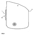
- FIG. 1 a device G with a housing H is shown in sections.
- the device G has a slide switch 1.
- the slide switch 1 has a touch surface 13.
- the touch surface 13 is raised relative to the housing H, so that a user can operate the slide switch 1 and easily reach.
- FIG. 2 is a device G with a slide switch 1 in an exploded view of the slide switch 1 is shown.
- the device G has two housing halves H, in which the slide switch 1 is inserted at the position O.
- the slide switch 1 has a touch surface 13.
- the slide switch 1 consists of a sliding part 2 and a fixedly arranged opposite this element 3.
- the sliding part 2 moves upon actuation of the slide switch 1 in a plane to the fixed element 3.
- the sliding part 2 has at least one further element 4, which firmly with the sliding part 2 is connectable.
- the further element 4 is rectangular, square, oval, round or n-shaped. But it can be used any other geometric shape.
- the further element 4 has an opening 12 into which the plunger 5 can be inserted and from which opening 12 the plunger 5 protrudes at least partially beyond the further element 4.
- the sliding part 2 further comprises springs 15, which are arranged in the direction of the plane of movement of the sliding part 2 to the fixed element 3 and the sliding part 2 at least partially project beyond.
- FIG. 3 is a Aufbruchanno a device G in the area of the slide switch 1 shown.
- two further elements 4 are integrated into the sliding part 2, which receive two plungers 5 each.
- the plunger 5 within a further element 4 are each offset from one another.
- Each of the two plungers 5 in a further element 4 projects in each case on a different side of the further element 4 in the manner described above.
- the fixed element 3 is easily recognizable.
- the fixed element 3 has at least one recess 6.
- the recesses 6 correspond to the plungers 5, which are arranged in the further element 4 of the sliding part 2.
- the plunger 5 slides this in the fixed element 3 existing openings 6.
- the plunger 5 slide into these openings 6 and form in this position latching positions of the slide switch 1 from.
- Each of these locking positions is associated with a contact pairing between fixedly arranged element 3 and sliding part 2, which then trigger a corresponding function in the device G.
- the characteristic of the slide switch 1 is adjustable.
- the characteristic of the slide switch 1 can be influenced. For each combination of depression 6 and plunger 5, a corresponding contact position and a corresponding contact closure between the sliding part 2 and fixed element 3 is provided.
- springs 15 are provided on the sliding part 2. In the end position of the slide switch 1, the respective spring 15 is pressed together and generates a counterforce. By the spring 15, the slide switch 1 does not remain in the end position, but jumps back to the previous position as soon as a user releases the slide switch 1 in the end position (end stop).
- FIG. 4 is a section through a device G and the housing H in the region of the slide switch 1 is shown. Again, the slider 2 and the fixed member 3 are shown. In addition, the further element 4, which is firmly connected to the sliding part 2, shown. There are in FIG. 4 two further elements 4 are shown, each with two opposing tappets 5, which slide along the arranged element 3 upon actuation of the slide switch 1 and sliding of the sliding member 2 in openings 6 of the fixed element 3. The openings 6 are in FIG. 4 not shown. By selecting two further elements 4, each with two tappets 5, a particularly uniform force distribution between the sliding part 2 and the fixed element 3 is provided. The springs 7 store the plunger 5 resiliently in another element. 4
- the force distribution for latching the further element 4 in the fixed element 3 on a (total) larger travel can be done or better distributed.
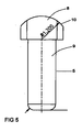
- a plunger 5 is shown in section.
- the plunger 5 is characterized by a head part 8 and a stem part 9.
- the head part 8 is wider than the stem part 9.
- the head part 8 has a rounding 10.
- a plunger 5 is shown in the form of a hammer.
- the head part 8 is parallelepiped-shaped with a rounding 10 in the upper region.
- the stem part 9 is firmly connected to the head part 8 and phased at the end.
- FIG. 7 shows a further embodiment of a plunger 5.
- the plunger 5 according to FIG. 7 again has a head part 8 and a stem part 9. Furthermore, a ring broadening 11 is present. The ring widening 11 is made wider than the opening 12 in the further element 4. In this way, a defined length of the projecting out of the plunger 5 from the further element 4 is given.
- FIG. 8 is a section through the plunger 5 according to FIG. 7 shown. Again, the ring broadening 11, the head part 8 with the rounding 10 and the stem part 9 are again shown here well.
Landscapes
- Engineering & Computer Science (AREA)
- Manufacturing & Machinery (AREA)
- Slide Switches (AREA)
- Push-Button Switches (AREA)
- Mechanisms For Operating Contacts (AREA)
Description
- Die Erfindung betrifft einen Schiebeschalter mit den Merkmalen der Patentanspruches 1. Es wird ein Schiebeschalter aufgezeigt, der eine bessere Kraftverteilung aufweist. Der Schiebeschalter besteht aus einem feststehenden Teil und einem zum feststehenden Teil verschiebbaren Teil, wobei der verschiebbare Teil in mindestens einer Ebene zum fest stehenden Teil verschiebbar ist.
- Es gibt eine große Anzahl von Schiebeschaltern, die einen Schieber mit beweglichen Kontakten und ein Basisteil oder ein Gehäuse mit stationären Kontakten umfassen. In solch einem Schiebeschalter werden, wenn die beweglichen Kontakte mit den stationären Kontakten verbunden oder von diesen getrennt werden, eine Schaltfunktion, eine Betriebsartenumschaltfunktion oder eine andere elektrische Funktion ausgeführt.
- Ein herkömmlicher Schiebeschalter, beispielsweise zum Einsatz in einem Diktiergerät, besteht aus zwei Teilen, einem verschiebbaren Teil, welcher beweglich gelagert ist, und einem gegenüber dem beweglichen Teil feststehenden Teil, der sogenannten Rastkulisse. Das bewegliche Teil wird über die Rastkulisse bewegt; es kann über diese verschoben werden. Die Rastkulisse weist hierbei Erhöhungen und Vertiefungen auf, über welche der verschiebbare Teil gleitet. Der verschiebbare Teil taucht beim Verschieben über die Rastkulisse in deren Vertiefungen ein. Das verschiebbare Teil weist dabei ein federndes Element auf, welches ermöglicht, dass der verschiebbare Teil den Unterschied zwischen Erhöhungen und Vertiefungen der Rastkulisse überwindet. Ist der verschiebbare Teil in der Vertiefung positioniert, werden elektrische Kontaktstellen des verschiebbaren Teils mit korrespondierenden Kontaktstellen verbunden. Es wird somit über diese Kontaktstellen bei Einrastung in der Vertiefung der Rastkulisse ein Kontakt geschlossen.
- Aus
EP 1 126 482 B1 ist ein multidirektionaler Gleitschalter bekannt. Dieser weist ein Gehäuse mit einem festen Kontaktteil und ein erstes Gleitteil sowie ein zweites Gleitteil auf, welche in einem Gehäuse angeordnet sind. Das erste Gleitteil ist mit dem zweiten Gleitteil gleitbar verbunden, so dass nur in Richtung einer von zwei sich kreuzenden Achsen relativ zum zweiten Gleitteil eine Bewegung erfolgen kann, wobei das zweite Gleitteil beweglich in die Richtung der anderen der beiden Achsen in Bezug auf das Gehäuse angeordnet ist. Das zweite Gleitteil ist durch eine Rückholkraft von mindestens einer Rückholfeder in eine neutrale Position rückführbar. Das erste Gleitteil ist mit einem Bedienknopf und einem beweglichen Kontaktteil ausgestattet. Bei der Bedienung des Bedienknopfes werden das erste und das zweite Gleitteil in die jeweilige Richtung bewegt, wobei das bewegliche Kontaktstück in Kontakt mit dem festen Kontaktstück und wenigstens einem der zusätzlich befestigten Kontaktstücke in Abhängigkeit von der Richtung, in der der Bedienknopf bewegt wird, gebracht wird. Das erste Gleitteil wird wenigstens durch die Rückholkraft von wenigstens einer auf dem zweiten Gleitteil installierten Rückholfeder in die neutrale Position in Bezug auf das zweite Gleitteil gebracht. - Aus
DE 102 24 773 B4 ist ein weiterer Schiebeschalter bekannt. Dieser Schiebeschalter umfasst ein Basisteil, wobei zwei Führungsnuten von vorgegebener Länge parallel zueinander auf einer Oberfläche angeordnet sind. Der Schieber ist auf dem Basisteil montiert, wobei der Schieber einen Schiebekörper umfasst, auf dem zwei Führungsnuten einer vorgegebenen Länge parallel zueinander in der unteren Oberfläche ausgebildet sind, so dass diese symmetrisch zum Mittelpunkt auf der unteren Oberfläche liegen. - Weiterhin ist eine Gleitbrücke, die aus zwei unteren und zwei oberen Brückenteilen gebildet ist, vorhanden, wobei die zwei unteren Brückenteile gleitbar entlang der zwei parallelen Führungsnuten in dem Basisteil angepasst sind und wobei die beiden oberen Brücken gleitbar entlang der zwei parallelen Führungsnuten in dem Schiebeschalter angepasst sind.
- Auf dem Basisteil ist eine Vielzahl von Kontaktblättchen beliebiger Form ausgebildet, in denen jeweils eine Gruppe von stationären Kontakten auf einem jeweils gedachten kreisförmigen Pfad mit vorgegebenen Radien mit einem Mittelpunkt auf der Oberfläche des Basisteils ausgebildet ist und eine Kontaktfeder auf der Seite des Schiebeschalters, die dem Basisteil zugewandt ist, montiert ist. Die Kontaktfeder weist Kontaktfederteile auf, die bewegliche Kontakte darstellen und radial bei gleichem oder ungleichem Winkel um eine Federplatte der Kontaktfeder angeordnet sind. Die stationären und die beweglichen Kontakte sind in der Ausgangslage so angeordnet, dass sie einander gegenüber liegen.
- Aus
US-A-4,904,828 A - Aus
US 3,983,355 A ist ein weiterer Schalter bekannt. Dieser Schalter besteht aus einem fest angeordneten Gehäuseteil und einem im fest angeordneten Gehäuseteil verschieblich gelagerten beweglichen Gehäuseteil. Das bewegliche Gehäuseteil ist im feststehenden Gehäuseteil angeordnet. Im beweglichen Gehäuseteil ist eine Durchgangsbohrung vorgesehen, in welcher sich eine Feder befindet, auf welcher jeweils an den Eingangsöffnungen der Durchgangsbohrung eine Kugel angeordnet ist. Mittels der Kugeln gleitet das bewegliche Element innerhalb des fest angeordneten Elementes. Im fest angeordneten Element sind Vertiefungen vorgesehen, in die bei der Bewegung des beweglichen Teiles innerhalb des fest angeordneten Elementes die Kugeln eingleiten und damit einen Rastpunkt definieren. - Aus
JP 58 101315 A - Aus
CN 2 924 759 Y ist ein Schieber offenbart. Ein Anschlag des Schiebers wird durch eine Verrastung eines vorgespannten Rastelementes in Bohrungen erreicht, die vom Benutzer betätigbar sind. - Nachteilig bei all diesen Schiebeschaltern ist, dass diese ein durch die Konstruktion vorgegebenes Rastverhalten und eine vorgegebene Bedienhärte haben. Ein Nutzer ist nicht in der Lage, das Rastverhalten des Schiebeschalters auf seine Bedürfnisse einzustellen. Die Härte bzw. die Kraft, welche aufzuwenden ist, um den Schiebeschalter von einem Rastpunkt in den anderen zu bewegen, ist nicht veränderbar. Außerdem wird bei der Bedienung der bekannten Schiebeschalter konstruktionsbedingt ein ungleichmäßiger Kraftaufwand benötigt, der häufig zu Verkantungen und gefühlter ruckartiger Bedienung führt.
- Aufgabe der vorliegenden Erfindung ist es, Schiebeschalter aufzuzeigen, die für einen Nutzer eine besonders gute Bedienbarkeit aufweisen.
- Diese Aufgabe wird anhand der Merkmale des Patentanspruches 1 gelöst.
- Vorteilhafte Ausgestaltungen der Erfindung ergeben sich anhand der weiteren Beschreibung, der abhängigen Ansprüche sowie der Figuren und der zugehörigen Figurenbeschreibung.
- Der erfindungsgemäße Schiebeschalter gemäß dem unabhängigen Anspruch 1 besteht aus einem verschiebbaren Element, einem sogenannten Gleitteil, und einem fest angeordneten Element.
- Das Gleitteil ist innerhalb des fest angeordneten Elementes in einer Ebene verschiebbar. Das Gleitteil weist mindestens ein weiteres Element auf, das mit dem Gleitteil fest verbindbar ist. Im weiteren Element ist mindestens ein beweglich gelagerter Stößel angeordnet, der senkrecht zur Verschiebungsebene des Gleitteils zum fest angeordneten Element im weiteren Element angeordnet ist. Der Stößel ragt aus dem weiteren Element an zumindest einer dem fest angeordneten Element zugeordneten Seite aus dem weiteren Element heraus. Das fest angeordnete Element weist Vertiefungen auf, welche zum aus dem weiteren Element herausragenden Stößel korrespondieren, so dass beim Bewegen des Gleitteils im fest angeordneten Element der Stößel in eine der Vertiefungen eingleitet und somit einen Rastpunkt des Schiebeschalters definiert.
- Gemäß der Ausführung nach Anspruch 2 ist bevorzugt, dass das weitere Element rechteckig, quadratisch, oval, rund oder vieleckig ist.
- Vorteilhaft gemäß der Ausführung nach Anspruch 3 ist, dass das Gleitteil mit dem weiteren Element und dessen mindestens einen Stößel und dem fest angeordneten Element mit den Vertiefungen eine Rastkulisse ausbildet. Dadurch ist die Rastkulisse im Schiebeschalter flexibel gestaltbar. Es kann durch die Vertiefungen und die bzw. den Stößel ein definiertes Einrasten als Schaltpunkt gewählt werden. Durch die Formwahl des Stößels und der Vertiefungen ist die Charakteristik des Schiebeschalters beeinflussbar. Außerdem kann durch eine geschickte Materialauswahl ebenfalls die Charakteristik des Schiebeschalters beeinflussbar gestaltet werden. Der mindestens eine Stößel ist im weiteren Element federnd gelagert. Hierdurch kann durch die Auswahl der Feder und deren Eigenschaft die Charakteristik des Schiebeschalters beeinflusst und bestimmt werden. Je nach Federhärte sind die Rastpunkte des Schiebeschalters stärker oder schwächer für einen Nutzer spürbar.
- In einer besonders vorteilhaften Ausgestaltung der Erfindung ist über eine Einstelleinheit am Schiebeschalter die Federhärte der Federn veränderbar, so dass ein Nutzer die Charakteristik des Schiebeschalters und dessen Rastverhalten auf seine Bedürfnisse einstellen kann.
- Gemäß der Ausführung nach Anspruch 4 ist bevorzugt, dass der mindestens eine Stößel im weiteren Element mittels einer Feder gelagert ist. Außerdem ist bevorzugt, dass die Feder eine Ringfeder, eine Spiralfeder oder eine Blattfeder ist.
- Gemäß der Ausführung nach Anspruch 5 ist bevorzugt, dass das weitere Element Platz für mehrere Stößel aufweist, die mittels Feder gelagert sind und dadurch die Kraftverteilung zur Rastung des weiteren Elementes im fest angeordneten Element auf einen (insgesamt) größeren Federweg erfolgen kann.
- Es ist vorgesehen, dass der Stößel aus einem Kopfteil und einem Stielteil besteht, wobei das Kopfteil eine Abrundung mit einem definierten Radius aufweist. Durch die Möglichkeit der Gestaltung des Stößels kann die Charakteristik des Schiebeschalters beeinflusst werden. So kann durch eine starke Abrundung ein tiefes Eintauchen des Stößels in eine Vertiefung gewählt werden.
- Es ist vorgesehen, dass der Stößel eine hammerartige Form oder im Kopfteil eine steckkopfartige Form mit einer Ringverbreiterung aufweist. Durch die hammerartige Form wird gewährleistet, dass der Stößel beim Verschieben des Gleitteils über das fest angeordnete Element eine gleichmäßige Reibung erzeugt und somit der Schiebeschalter ein gleichmäßiges Gleitverhalten aufweist. Durch die Ausgestaltung des Stößels im Kopfteil mit einer steckkopfartigen Form wird erreicht, dass der Stößel gut in die Vertiefungen des fest angeordneten Elements eingleitet und einen definierten Rastpunkt erzeugt. Durch die Ringverbreiterung wird verhindert, dass der Stößel aus dem weiteren Element herausgleitet. Durch die Ringverbreiterung wird verhindert, dass der Stößel zu weit durch die Öffnung im weiteren Element herausragt. Außerdem ist bevorzugt, dass das weitere Element Öffnungen aufweist, in welche ein Stößel einführbar ist, wobei die Ringverbreiterung des Stößels größer ist als die Öffnungen. Vorteilhaft ist darüber hinaus, dass der Stößel aus kompressiblem Material besteht. Dadurch wird ein besonders gutes Gleitverhalten des Schiebeschalters erzeugt.
- Es ist vorgesehen, dass die Feder zwischen den Seitenwänden des weiteren Elements angeordnet ist, senkrecht zur Bewegungsebene des Gleitteils zum fest angeordneten Element und der Stößel mit seinem Stielteil oder der Ringverbreiterung die Feder mechanisch kontaktiert, so dass der Stößel mit einer definierten Kraft aus der Öffnung gegen das fest angeordnete Element drückbar ist.
- Gemäß der Ausführung nach Anspruch 6 ist bevorzugt, dass der Schiebeschalter in ein Gerät einbaubar ist und/oder dass das Gerät ein Diktiergerät oder ein Mobiltelefon oder ein Gerät der Unterhaltungselektronik oder ein Gerät der Kommunikationselektronik ist.
- Gemäß der Ausführung nach Anspruch 7 ist bevorzugt, dass das Gleitteil mindestens eine Kontaktstelle aufweist und/oder dass die mindestens eine Kontaktstelle des Gleitteils mit Gegenkontaktstellen im fest angeordneten Element einen Kontakt bei Berührung schließt.
- Gemäß der Ausführung nach Anspruch 8 ist bevorzugt, dass zu jeder der Vertiefungen des fest angeordneten Elements mindestens eine Kontaktstelle am Gleitteil vorhanden ist, welche mit mindestens einer Gegenkontaktstelle im oder am fest angeordneten Element einen Kontakt bei Berührung schließt.
- Gemäß der Ausführung nach Anspruch 9 ist bevorzugt, dass der Schiebeschalter eine Tastfläche aufweist, welche sich über ein Gehäuse des Gerätes erhebt.
- Gemäß der Ausführung nach Anspruch 10 ist bevorzugt, dass der Schiebeschalter mindestens zwei Schaltpunkte aufweist.
- In der weiteren nachfolgenden Beschreibung werden weitere Merkmale und Einzelheiten der Erfindung in Zusammenhang mit den beigefügten Zeichnungen anhand von Ausführungsbeispielen näher erläutert. Dabei sind in einzelnen Varianten beschriebene Merkmale und Zusammenhänge grundsätzlich auf alle Ausführungsbeispiele übertragbar. Es erfolgt keine Einschränkung der Erfindung auf eine der nachfolgenden konkreten Ausführungsbeispiele bzw. des nachfolgenden Ausführungsbeispiels. Es werden bei der Figurenbeschreibung für gleiche Elemente gleiche Bezugszeichen in allen Figuren verwendet. Dies dient der besseren Verständlichkeit der Beschreibung.
- Es zeigen:
- FIG 1
- eine Draufsicht auf ein Gerät mit Schiebeschalter,
- FIG 2
- ein Gerät mit erfindungsgemäßem Schiebeschalter in Explosionsdarstellung,
- FIG 3
- eine Aufbruchzeichnung eines Gerätes mit erfindungsgemäßem Schiebeschalter,
- FIG 4
- einen Schnitt durch ein Gerät mit erfindungsgemäßem Schiebeschalter,
- FIG 5
- einen Stößel,
- FIG 6
- einen weiteren Stößel,
- FIG 7
- einen weiteren Stößel und
- FIG 8
- einen weiteren Stößel.
- In
FIG 1 ist ein Gerät G mit einem Gehäuse H abschnittsweise dargestellt. Das Gerät G weist einen Schiebeschalter 1 auf. Der Schiebeschalter 1 weist eine Tastfläche 13 auf. Die Tastfläche 13 ist gegenüber dem Gehäuse H erhöht, so dass ein Nutzer den Schiebeschalter 1 bedienen und einfach erreichen kann. - In
FIG 2 ist ein Gerät G mit einem Schiebeschalter 1 in Explosionsdarstellung des Schiebeschalters 1 dargestellt. Das Gerät G weist zwei Gehäusehälften H auf, in welche der Schiebeschalter 1 an der Position O eingefügt wird. - Der erfindungsgemäße Schiebeschalter 1 weist eine Tastfläche 13 auf. Der Schiebeschalter 1 besteht aus einem Gleitteil 2 und einem diesen gegenüber fest angeordneten Element 3. Das Gleitteil 2 bewegt sich bei Betätigen des Schiebeschalters 1 in einer Ebene zum fest angeordneten Element 3. Das Gleitteil 2 weist zumindest ein weiteres Element 4 auf, welches fest mit dem Gleitteil 2 verbindbar ist. In diesem weiteren Element 4, welches vorzugsweise rechteckig ausgestaltet ist, ist mindestens ein Stößel 5, gelagert über eine Feder 7, angeordnet.
- In einer weiteren Ausführungsform der Erfindung ist das weitere Element 4 rechteckig, quadratisch, oval, rund oder n-eckig ausgestaltet. Es ist aber jede weitere geometrische Form verwendbar.
- Weiterhin weist das weitere Element 4 eine Öffnung 12 auf, in welche der Stößel 5 einschiebbar ist und aus welcher Öffnung 12 der Stößel 5 zumindest teilweise über das weitere Element 4 herausragt. Das Gleitteil 2 weist weiterhin Federn 15 auf, welche in Richtung der Bewegungsebene des Gleitteils 2 zum fest angeordneten Element 3 angeordnet sind und das Gleitteil 2 zumindest teilweise überragen.
- In
FIG 3 ist eine Aufbruchzeichnung eines Gerätes G im Bereich des Schiebeschalters 1 dargestellt. In diesem Ausführungsbeispiel sind in das Gleitteil 2 zwei weitere Elemente 4 integriert, welche jeweils zwei Stößel 5 aufnehmen. Die Stößel 5 innerhalb eines weiteren Elementes 4 sind jeweils versetzt zueinander angeordnet. Jeder der zwei Stößel 5 in einem weiteren Element 4 ragt jeweils auf einer anderen Seite des weiteren Elements 4 in vorbeschriebener Weise hinaus. - In
FIG 3 ist das fest angeordnete Element 3 gut erkennbar. Das fest angeordnete Element 3 weist mindestens eine Vertiefung 6 auf. Die Vertiefungen 6 korrespondieren zu den Stößeln 5, welche im weiteren Element 4 des Gleitteils 2 angeordnet sind. Beim Verschieben des Gleitteils 2 entlang des fest angeordneten Elements 3 gleiten die Stößel 5, welche über die Federn 7 gelagert sind, entlang der zu den Stößeln 5 anliegenden Flächen des fest angeordneten Elements 3. Die Stößel 5 gleiten hierbei dann in die im fest angeordneten Element 3 vorhandenen Öffnungen 6. Die Stößel 5 gleiten in diese Öffnungen 6 ein und bilden in dieser Position Rastpositionen des Schiebeschalters 1 aus. Jeder dieser Rastpositionen ist eine Kontaktpaarung zwischen fest angeordnetem Element 3 und Gleitteil 2 zugeordnet, welche dann eine entsprechende Funktion im Gerät G auslösen. Durch die Form der Stößel 5 sowie der korrespondierenden Öffnungen 6 im fest angeordneten Element 3 ist die Charakteristik des Schiebeschalters 1 einstellbar. Durch die Wahl der Federn 7, welche die Stößel 5 mit vorgegebener Kraft aus dem weiteren Element 4 durch dessen Öffnungen 12 gegen das fest angeordnete Element 3 drücken, ist ebenfalls die Charakteristik des Schiebeschalters 1 beeinflussbar. Zu jeder Kombination von Vertiefung 6 und Stößel 5 ist eine entsprechende Kontaktposition und ein entsprechender Kontaktschluss zwischen Gleitteil 2 und fest angeordnetem Element 3 vorgesehen. - Im Weiteren sind Federn 15 am Gleitteil 2 vorgesehen. In der Endstellung des Schiebeschalters 1 wird jeweils die entsprechende Feder 15 zusammengepresst und erzeugt eine Gegenkraft. Durch die Feder 15 verbleibt der Schiebeschalter 1 nicht in der Endposition, sondern springt in die vorherige Position zurück, sobald ein Nutzer den Schiebeschalter 1 in der Endstellung (Endanschlag) loslässt.
- In
FIG 4 ist ein Schnitt durch ein Gerät G und dessen Gehäuse H im Bereich des Schiebeschalters 1 dargestellt. Es sind wiederum das Gleitteil 2 und das fest angeordnete Element 3 dargestellt. Im Weiteren ist das weitere Element 4, das mit dem Gleitteil 2 fest verbindbar ist, dargestellt. Es sind inFigur 4 zwei weitere Elemente 4 dargestellt, jeweils mit zwei gegenüberliegenden Stößeln 5, welche entlang des angeordneten Elementes 3 beim Betätigen des Schiebeschalters 1 und Verschieben des Gleitteils 2 in Öffnungen 6 des fest angeordneten Elementes 3 gleiten. Die Öffnungen 6 sind inFigur 4 nicht dargestellt. Durch die Auswahl von zwei weiteren Elementen 4 mit jeweils zwei Stößeln 5 ist eine besonders gleichmäßige Kraftverteilung zwischen Gleitteil 2 und fest angeordnetem Element 3 gegeben. Die Federn 7 lagern die Stößel 5 federnd im weiteren Element 4. - In einer weiteren Ausgestaltung der Erfindung weist das weitere Element 4 Platz oder Bautiefe oder Bauraum für mehrere Stößel 5 auf, die wiederum entweder jeweils mittels einer Feder 7 oder gemeinsam mittels einer Feder 7 oder in Kombination mit einer oder mehreren Federn 7 gelagert sind. Dadurch kann die Kraftverteilung zur Rastung des weiteren Elementes 4 im fest angeordneten Element 3 auf einen (insgesamt) größeren Federweg erfolgen oder bessert verteilt werden.
- In
FIG 5 ist ein Stößel 5 im Schnitt dargestellt. Der Stößel 5 ist gekennzeichnet durch ein Kopfteil 8 und ein Stielteil 9. Der Kopfteil 8 ist breiter als der Stielteil 9. Im Weiteren weist der Kopfteil 8 eine Rundung 10 auf. Durch die geschickte Wahl des Materials und der Form des Stößels 5 ist die Charakteristik des Schiebeschalters 1 beeinflussbar. - In
FIG 6 ist ein Stößel 5 in Form eines Hammers dargestellt. Der Kopfteil 8 ist quaderförmig ausgebildet mit einer Abrundung 10 im oberen Bereich. Der Stielteil 9 ist fest mit dem Kopfteil 8 verbunden und am Ende angephast. -
FIG 7 zeigt eine weitere Ausgestaltungsform eines Stößels 5. Der Stößel 5 gemäßFigur 7 weist wiederum ein Kopfteil 8 sowie ein Stielteil 9 auf. Weiterhin ist eine Ringverbreiterung 11 vorhanden. Die Ringverbreiterung 11 ist breiter ausgestaltet als die Öffnung 12 im weiteren Element 4. Auf diese Weise ist eine definierte Länge des Herausragens des Stößels 5 aus dem weiteren Element 4 vorgegeben. - In
FIG 8 ist ein Schnitt durch den Stößel 5 gemäßFIG 7 dargestellt. Hier sind wiederum gut die Ringverbreiterung 11, der Kopfteil 8 mit der Abrundung 10 sowie der Stielteil 9 dargestellt.
Claims (10)
- Schiebeschalter (1) bestehend aus einem Gleitteil (2) und einem fest angeordneten Element (3), wobei das Gleitteil (2) innerhalb des fest angeordneten Elementes (3) in einer Verschiebungsebene verschiebbar ist, das Gleitteil (2) mindestens ein weiteres Element (4) aufweist, das mit dem Gleitteil (2) fest verbindbar ist, und im weiteren Element (4) mindestens ein beweglich gelagerter Stößel (5) angeordnet ist, der senkrecht zur Verschiebungsebene des Gleitteils (2) zum fest angeordneten Element (3) im weiteren Element (4) angeordnet ist, wobei der Stößel (5) aus dem weiteren Element (4) an zumindest einer dem fest angeordneten Element (3) zugeordneten Seite herausragt, das fest angeordnete Element (3) Vertiefungen (6) aufweist, welche zum aus dem weiteren Element (4) herausragenden Stößel (5) korrespondieren, so dass beim Bewegen des Gleitteils (2) im fest angeordneten Element (3) der Stößel (5) in eine der Vertiefungen (6) eingeleitet und somit einen Rastpunkt des Schiebeschalters (1) definiert wobei der Stößel (5) aus einem Kopfteil (8) und einem Stielteil (9) besteht und das Kopfteil (8) eine Abrundung (10) mit einem definierten Radius aufweist dadurch gekennzeichnet, dass der Stößel (5) im Kopfteil (8) eine steckkopfartige Form mit einer Ringverbreiterung (11) aufweist und das weitere Element (4) Seitenwände mit Öffnungen (12) aufweist, in welchen der Stößel (5) einführbar ist, wobei die Ringverbreiterung (11) des Stößels (5) größer ist als die Öffnung (12), wobei eine Feder (7) zwischen den Seitenwänden des weiteren Elements (4) angeordnet ist, senkrecht zur Bewegungsebene des Gleitteils (2) zum fest angeordneten Element (3), und der Stößel (5) mit seiner Ringverbreiterung (11) die Feder (7) mechanisch kontaktiert, so dass der Stößel (5) mit einer definierten Kraft aus der Öffnung (12) gegen das fest angeordnete Element (3) drückbar ist.
- Schiebeschalter (1) nach Anspruch 1, dadurch gekennzeichnet, dass das weitere Element (4) rechteckig, quadratisch, oval, rund oder vieleckig ist.
- Schiebeschalter (S) nach Anspruch 1 oder 2, dadurch gekennzeichnet, dass das Gleitteil (2) mit dem weiteren Element (4) und dessen mindestens einen Stößel (5) und dem fest angeordneten Element (3) mit den Vertiefungen (6) eine Rastkulisse ausbildet und/oder der mindestens eine Stößel (5) im weiteren Element (4) federnd gelagert ist.
- Schiebeschalter (1) nach Anspruch 3, dadurch gekennzeichnet, dass der mindestens eine Stößel (5) im weiteren Element (4) mittels der Feder (7) gelagert ist und die Feder (7) eine Ringfeder, eine Spiralfeder oder eine Blattfeder ist.
- Schiebeschalter (1) nach einem der vorangegangenen Ansprüche dadurch gekennzeichnet, dass das weitere Element (4) Platz für mehrere Stößel (5) aufweist, die mittels der Feder (7) gelagert sind und dadurch die Kraftverteilung zur Rastung des weiteren Elementes (4) im fest angeordneten Element (3) auf einen veränderbaren Federweg erfolgen kann.
- Schiebeschalter (1) nach einem der vorangehenden Ansprüche, dadurch gekennzeichnet, dass der Schiebeschalter (1) in ein Gerät (G) einbaubar ist und das Gerät (G) ein Diktiergerät oder ein Mobiltelefon oder ein Gerät der Unterhaltungselektronik oder ein Gerät der Kommunikationselektronik ist.
- Schiebeschalter (1) nach einem der vorangehenden Ansprüche, dadurch gekennzeichnet, dass das Gleitteil (2) mindestens eine Kontaktstelle aufweist und die mindestens eine Kontaktstelle des Gleitteils (2) mit Gegenkontaktstellen im fest angeordneten Element (3) einen Kontakt bei Berührung schließt.
- Schiebeschalter (1) nach einem der vorangehenden Ansprüche, dadurch gekennzeichnet, dass zu jeder der Vertiefungen (6) des fest angeordneten Elements (3) mindestens eine Kontaktstelle am Gleitteil (2) vorhanden ist, welche mit mindestens einer Gegenkontaktstelle im oder am fest angeordneten Element (3) einen Kontakt bei Berührung schließt.
- Schiebeschalter (1) nach einem der vorangehenden Ansprüche, dadurch gekennzeichnet, dass der Schiebeschalter (1) eine Tastfläche (13) aufweist, welche sich über ein Gehäuse (H) des Gerätes (G) erhebt.
- Schiebeschalter (1) nach einem der vorangehenden Ansprüche, dadurch gekennzeichnet, dass der Schiebeschalter (1) mindestens zwei Schaltpunkte aufweist.
Priority Applications (1)
| Application Number | Priority Date | Filing Date | Title |
|---|---|---|---|
| EP11005529A EP2375430B1 (de) | 2009-07-17 | 2010-07-08 | Schiebeschalter |
Applications Claiming Priority (1)
| Application Number | Priority Date | Filing Date | Title |
|---|---|---|---|
| DE102009026191A DE102009026191A1 (de) | 2009-07-17 | 2009-07-17 | Schiebeschalter |
Related Child Applications (1)
| Application Number | Title | Priority Date | Filing Date |
|---|---|---|---|
| EP11005529A Division-Into EP2375430B1 (de) | 2009-07-17 | 2010-07-08 | Schiebeschalter |
Publications (3)
| Publication Number | Publication Date |
|---|---|
| EP2276044A2 EP2276044A2 (de) | 2011-01-19 |
| EP2276044A3 EP2276044A3 (de) | 2011-04-20 |
| EP2276044B1 true EP2276044B1 (de) | 2014-10-29 |
Family
ID=42938168
Family Applications (2)
| Application Number | Title | Priority Date | Filing Date |
|---|---|---|---|
| EP10168923.0A Not-in-force EP2276044B1 (de) | 2009-07-17 | 2010-07-08 | Schiebeschalter |
| EP11005529A Not-in-force EP2375430B1 (de) | 2009-07-17 | 2010-07-08 | Schiebeschalter |
Family Applications After (1)
| Application Number | Title | Priority Date | Filing Date |
|---|---|---|---|
| EP11005529A Not-in-force EP2375430B1 (de) | 2009-07-17 | 2010-07-08 | Schiebeschalter |
Country Status (2)
| Country | Link |
|---|---|
| EP (2) | EP2276044B1 (de) |
| DE (2) | DE102009061041B4 (de) |
Family Cites Families (9)
| Publication number | Priority date | Publication date | Assignee | Title |
|---|---|---|---|---|
| JPS5021676U (de) * | 1973-06-21 | 1975-03-11 | ||
| JPS58101315A (ja) | 1981-12-11 | 1983-06-16 | Matsushita Electric Ind Co Ltd | 摺動式電気部品 |
| DE8702343U1 (de) * | 1987-02-16 | 1987-04-02 | Hella KG Hueck & Co, 4780 Lippstadt | Innenleuchte für Fahrzeuge mit einem Schiebeschalter |
| US4904828A (en) | 1988-09-23 | 1990-02-27 | Emhart Industries, Inc. | Multi-circuit slide switch assembly with distinct plunger operated switch |
| JP2001307599A (ja) | 2000-02-15 | 2001-11-02 | Alps Electric Co Ltd | 多方向スライドスイッチ |
| JP2003059374A (ja) | 2001-06-04 | 2003-02-28 | Mic Electron Co | スライドスイッチ |
| US6597796B2 (en) * | 2001-11-09 | 2003-07-22 | Chao-Chih Chang | Microphone with a variable resistance switch |
| US6930268B1 (en) * | 2002-05-20 | 2005-08-16 | Robert M. Tuniewicz | On-off electrical switch having quick make-brake spring loaded plunger mechanism |
| CN2924759Y (zh) | 2006-04-25 | 2007-07-18 | 康舒科技股份有限公司 | 具有强制保护措施的电压选择开关 |
-
2009
- 2009-07-17 DE DE102009061041.3A patent/DE102009061041B4/de not_active Expired - Fee Related
- 2009-07-17 DE DE102009026191A patent/DE102009026191A1/de not_active Withdrawn
-
2010
- 2010-07-08 EP EP10168923.0A patent/EP2276044B1/de not_active Not-in-force
- 2010-07-08 EP EP11005529A patent/EP2375430B1/de not_active Not-in-force
Also Published As
| Publication number | Publication date |
|---|---|
| DE102009061041B4 (de) | 2018-10-31 |
| EP2276044A3 (de) | 2011-04-20 |
| DE102009061041A1 (de) | 2011-01-27 |
| DE102009026191A1 (de) | 2011-01-27 |
| EP2375430B1 (de) | 2012-12-05 |
| EP2375430A1 (de) | 2011-10-12 |
| EP2276044A2 (de) | 2011-01-19 |
Similar Documents
| Publication | Publication Date | Title |
|---|---|---|
| DE10324295B4 (de) | Elektrischer Schalter | |
| DE2346392A1 (de) | Tastatur, insbesondere fuer elektronische rechengeraete | |
| DE2330730A1 (de) | Schalttaste mit einem magnetschaltwerk | |
| DE3208559C2 (de) | Tastatur | |
| DE19829811C2 (de) | Mehrrichtungs-Eingabevorrichtung | |
| DE3613702C2 (de) | ||
| DE2537284A1 (de) | Prellfreier elektrischer schalter | |
| EP0344625B1 (de) | Elektrischer Tastschalter | |
| DE102013107001B4 (de) | Betätigungseinrichtung für ein Kraftfahrzeug | |
| DE2942720C2 (de) | Drucktaste mit Schnappwirkung | |
| DE3442173A1 (de) | Elektrischer schalter gedrungener bauart | |
| EP2375430B1 (de) | Schiebeschalter | |
| DE102021112594A1 (de) | Tastatur sowie zugehörige Taste und zugehöriger Einstellmechanismus | |
| DE102010012908B4 (de) | Multifunktionsschalter | |
| EP2228811A2 (de) | Schaltereinsatz eines elektrischen Installationsgerätes | |
| DE102009026214B4 (de) | Schiebeschalter | |
| DE3900394C2 (de) | ||
| DE3107316A1 (de) | "schiebeschalter" | |
| DE10247093B3 (de) | Navigationsschalter | |
| DE10032518C1 (de) | Mehrstufige elektrische Schaltvorrichtung | |
| DE20117514U1 (de) | Wippenschalter | |
| EP1995746B1 (de) | Schiebeschalter | |
| DE102023109472B3 (de) | Nottasteinrichtung einer Türverriegelung mit einem Notausschalter | |
| DE3111407A1 (de) | Tastenschalter | |
| EP1501108A1 (de) | Elektrischer Mehrwegeschalter |
Legal Events
| Date | Code | Title | Description |
|---|---|---|---|
| PUAI | Public reference made under article 153(3) epc to a published international application that has entered the european phase |
Free format text: ORIGINAL CODE: 0009012 |
|
| AK | Designated contracting states |
Kind code of ref document: A2 Designated state(s): AL AT BE BG CH CY CZ DE DK EE ES FI FR GB GR HR HU IE IS IT LI LT LU LV MC MK MT NL NO PL PT RO SE SI SK SM TR |
|
| AX | Request for extension of the european patent |
Extension state: BA ME RS |
|
| PUAL | Search report despatched |
Free format text: ORIGINAL CODE: 0009013 |
|
| AK | Designated contracting states |
Kind code of ref document: A3 Designated state(s): AL AT BE BG CH CY CZ DE DK EE ES FI FR GB GR HR HU IE IS IT LI LT LU LV MC MK MT NL NO PL PT RO SE SI SK SM TR |
|
| AX | Request for extension of the european patent |
Extension state: BA ME RS |
|
| RIC1 | Information provided on ipc code assigned before grant |
Ipc: H01H 3/50 20060101AFI20101022BHEP Ipc: H01H 15/24 20060101ALI20110316BHEP Ipc: H01H 11/00 20060101ALI20110316BHEP |
|
| DAC | Divisional application: reference to earlier application (deleted) | ||
| 17P | Request for examination filed |
Effective date: 20111020 |
|
| 17Q | First examination report despatched |
Effective date: 20140206 |
|
| RIC1 | Information provided on ipc code assigned before grant |
Ipc: H01H 15/24 20060101ALI20140411BHEP Ipc: H01H 11/00 20060101ALI20140411BHEP Ipc: H01H 3/50 20060101AFI20140411BHEP Ipc: H01H 15/06 20060101ALN20140411BHEP |
|
| GRAP | Despatch of communication of intention to grant a patent |
Free format text: ORIGINAL CODE: EPIDOSNIGR1 |
|
| INTG | Intention to grant announced |
Effective date: 20140602 |
|
| GRAS | Grant fee paid |
Free format text: ORIGINAL CODE: EPIDOSNIGR3 |
|
| GRAA | (expected) grant |
Free format text: ORIGINAL CODE: 0009210 |
|
| AK | Designated contracting states |
Kind code of ref document: B1 Designated state(s): AL AT BE BG CH CY CZ DE DK EE ES FI FR GB GR HR HU IE IS IT LI LT LU LV MC MK MT NL NO PL PT RO SE SI SK SM TR |
|
| REG | Reference to a national code |
Ref country code: GB Ref legal event code: FG4D Free format text: NOT ENGLISH |
|
| REG | Reference to a national code |
Ref country code: CH Ref legal event code: EP |
|
| REG | Reference to a national code |
Ref country code: AT Ref legal event code: REF Ref document number: 693922 Country of ref document: AT Kind code of ref document: T Effective date: 20141115 |
|
| REG | Reference to a national code |
Ref country code: IE Ref legal event code: FG4D Free format text: LANGUAGE OF EP DOCUMENT: GERMAN |
|
| REG | Reference to a national code |
Ref country code: DE Ref legal event code: R096 Ref document number: 502010008132 Country of ref document: DE Effective date: 20141204 |
|
| REG | Reference to a national code |
Ref country code: SE Ref legal event code: TRGR |
|
| REG | Reference to a national code |
Ref country code: NL Ref legal event code: T3 |
|
| REG | Reference to a national code |
Ref country code: LT Ref legal event code: MG4D |
|
| PG25 | Lapsed in a contracting state [announced via postgrant information from national office to epo] |
Ref country code: FI Free format text: LAPSE BECAUSE OF FAILURE TO SUBMIT A TRANSLATION OF THE DESCRIPTION OR TO PAY THE FEE WITHIN THE PRESCRIBED TIME-LIMIT Effective date: 20141029 Ref country code: LT Free format text: LAPSE BECAUSE OF FAILURE TO SUBMIT A TRANSLATION OF THE DESCRIPTION OR TO PAY THE FEE WITHIN THE PRESCRIBED TIME-LIMIT Effective date: 20141029 Ref country code: NO Free format text: LAPSE BECAUSE OF FAILURE TO SUBMIT A TRANSLATION OF THE DESCRIPTION OR TO PAY THE FEE WITHIN THE PRESCRIBED TIME-LIMIT Effective date: 20150129 Ref country code: PT Free format text: LAPSE BECAUSE OF FAILURE TO SUBMIT A TRANSLATION OF THE DESCRIPTION OR TO PAY THE FEE WITHIN THE PRESCRIBED TIME-LIMIT Effective date: 20150302 Ref country code: IS Free format text: LAPSE BECAUSE OF FAILURE TO SUBMIT A TRANSLATION OF THE DESCRIPTION OR TO PAY THE FEE WITHIN THE PRESCRIBED TIME-LIMIT Effective date: 20150228 Ref country code: ES Free format text: LAPSE BECAUSE OF FAILURE TO SUBMIT A TRANSLATION OF THE DESCRIPTION OR TO PAY THE FEE WITHIN THE PRESCRIBED TIME-LIMIT Effective date: 20141029 |
|
| PG25 | Lapsed in a contracting state [announced via postgrant information from national office to epo] |
Ref country code: GR Free format text: LAPSE BECAUSE OF FAILURE TO SUBMIT A TRANSLATION OF THE DESCRIPTION OR TO PAY THE FEE WITHIN THE PRESCRIBED TIME-LIMIT Effective date: 20150130 Ref country code: CY Free format text: LAPSE BECAUSE OF FAILURE TO SUBMIT A TRANSLATION OF THE DESCRIPTION OR TO PAY THE FEE WITHIN THE PRESCRIBED TIME-LIMIT Effective date: 20141029 Ref country code: PL Free format text: LAPSE BECAUSE OF FAILURE TO SUBMIT A TRANSLATION OF THE DESCRIPTION OR TO PAY THE FEE WITHIN THE PRESCRIBED TIME-LIMIT Effective date: 20141029 Ref country code: LV Free format text: LAPSE BECAUSE OF FAILURE TO SUBMIT A TRANSLATION OF THE DESCRIPTION OR TO PAY THE FEE WITHIN THE PRESCRIBED TIME-LIMIT Effective date: 20141029 Ref country code: HR Free format text: LAPSE BECAUSE OF FAILURE TO SUBMIT A TRANSLATION OF THE DESCRIPTION OR TO PAY THE FEE WITHIN THE PRESCRIBED TIME-LIMIT Effective date: 20141029 |
|
| REG | Reference to a national code |
Ref country code: FR Ref legal event code: PLFP Year of fee payment: 6 |
|
| REG | Reference to a national code |
Ref country code: DE Ref legal event code: R097 Ref document number: 502010008132 Country of ref document: DE |
|
| PG25 | Lapsed in a contracting state [announced via postgrant information from national office to epo] |
Ref country code: EE Free format text: LAPSE BECAUSE OF FAILURE TO SUBMIT A TRANSLATION OF THE DESCRIPTION OR TO PAY THE FEE WITHIN THE PRESCRIBED TIME-LIMIT Effective date: 20141029 Ref country code: RO Free format text: LAPSE BECAUSE OF FAILURE TO SUBMIT A TRANSLATION OF THE DESCRIPTION OR TO PAY THE FEE WITHIN THE PRESCRIBED TIME-LIMIT Effective date: 20141029 Ref country code: CZ Free format text: LAPSE BECAUSE OF FAILURE TO SUBMIT A TRANSLATION OF THE DESCRIPTION OR TO PAY THE FEE WITHIN THE PRESCRIBED TIME-LIMIT Effective date: 20141029 Ref country code: DK Free format text: LAPSE BECAUSE OF FAILURE TO SUBMIT A TRANSLATION OF THE DESCRIPTION OR TO PAY THE FEE WITHIN THE PRESCRIBED TIME-LIMIT Effective date: 20141029 Ref country code: SK Free format text: LAPSE BECAUSE OF FAILURE TO SUBMIT A TRANSLATION OF THE DESCRIPTION OR TO PAY THE FEE WITHIN THE PRESCRIBED TIME-LIMIT Effective date: 20141029 |
|
| PG25 | Lapsed in a contracting state [announced via postgrant information from national office to epo] |
Ref country code: IT Free format text: LAPSE BECAUSE OF FAILURE TO SUBMIT A TRANSLATION OF THE DESCRIPTION OR TO PAY THE FEE WITHIN THE PRESCRIBED TIME-LIMIT Effective date: 20141029 |
|
| PLBE | No opposition filed within time limit |
Free format text: ORIGINAL CODE: 0009261 |
|
| STAA | Information on the status of an ep patent application or granted ep patent |
Free format text: STATUS: NO OPPOSITION FILED WITHIN TIME LIMIT |
|
| 26N | No opposition filed |
Effective date: 20150730 |
|
| PG25 | Lapsed in a contracting state [announced via postgrant information from national office to epo] |
Ref country code: SI Free format text: LAPSE BECAUSE OF FAILURE TO SUBMIT A TRANSLATION OF THE DESCRIPTION OR TO PAY THE FEE WITHIN THE PRESCRIBED TIME-LIMIT Effective date: 20141029 Ref country code: MC Free format text: LAPSE BECAUSE OF FAILURE TO SUBMIT A TRANSLATION OF THE DESCRIPTION OR TO PAY THE FEE WITHIN THE PRESCRIBED TIME-LIMIT Effective date: 20141029 |
|
| REG | Reference to a national code |
Ref country code: CH Ref legal event code: PL |
|
| PG25 | Lapsed in a contracting state [announced via postgrant information from national office to epo] |
Ref country code: LU Free format text: LAPSE BECAUSE OF FAILURE TO SUBMIT A TRANSLATION OF THE DESCRIPTION OR TO PAY THE FEE WITHIN THE PRESCRIBED TIME-LIMIT Effective date: 20150708 |
|
| REG | Reference to a national code |
Ref country code: DE Ref legal event code: R082 Ref document number: 502010008132 Country of ref document: DE Representative=s name: DIE PATENTERIE GBR PATENT- UND RECHTSANWALTSSO, DE |
|
| REG | Reference to a national code |
Ref country code: IE Ref legal event code: MM4A |
|
| PG25 | Lapsed in a contracting state [announced via postgrant information from national office to epo] |
Ref country code: LI Free format text: LAPSE BECAUSE OF NON-PAYMENT OF DUE FEES Effective date: 20150731 Ref country code: CH Free format text: LAPSE BECAUSE OF NON-PAYMENT OF DUE FEES Effective date: 20150731 |
|
| REG | Reference to a national code |
Ref country code: FR Ref legal event code: PLFP Year of fee payment: 7 |
|
| PG25 | Lapsed in a contracting state [announced via postgrant information from national office to epo] |
Ref country code: IE Free format text: LAPSE BECAUSE OF NON-PAYMENT OF DUE FEES Effective date: 20150708 |
|
| PG25 | Lapsed in a contracting state [announced via postgrant information from national office to epo] |
Ref country code: MT Free format text: LAPSE BECAUSE OF FAILURE TO SUBMIT A TRANSLATION OF THE DESCRIPTION OR TO PAY THE FEE WITHIN THE PRESCRIBED TIME-LIMIT Effective date: 20141029 |
|
| PG25 | Lapsed in a contracting state [announced via postgrant information from national office to epo] |
Ref country code: SM Free format text: LAPSE BECAUSE OF FAILURE TO SUBMIT A TRANSLATION OF THE DESCRIPTION OR TO PAY THE FEE WITHIN THE PRESCRIBED TIME-LIMIT Effective date: 20141029 Ref country code: BG Free format text: LAPSE BECAUSE OF FAILURE TO SUBMIT A TRANSLATION OF THE DESCRIPTION OR TO PAY THE FEE WITHIN THE PRESCRIBED TIME-LIMIT Effective date: 20141029 Ref country code: HU Free format text: LAPSE BECAUSE OF FAILURE TO SUBMIT A TRANSLATION OF THE DESCRIPTION OR TO PAY THE FEE WITHIN THE PRESCRIBED TIME-LIMIT; INVALID AB INITIO Effective date: 20100708 |
|
| REG | Reference to a national code |
Ref country code: FR Ref legal event code: PLFP Year of fee payment: 8 |
|
| PG25 | Lapsed in a contracting state [announced via postgrant information from national office to epo] |
Ref country code: BE Free format text: LAPSE BECAUSE OF NON-PAYMENT OF DUE FEES Effective date: 20150731 |
|
| PG25 | Lapsed in a contracting state [announced via postgrant information from national office to epo] |
Ref country code: TR Free format text: LAPSE BECAUSE OF FAILURE TO SUBMIT A TRANSLATION OF THE DESCRIPTION OR TO PAY THE FEE WITHIN THE PRESCRIBED TIME-LIMIT Effective date: 20141029 |
|
| REG | Reference to a national code |
Ref country code: DE Ref legal event code: R082 Ref document number: 502010008132 Country of ref document: DE Representative=s name: DIE PATENTERIE GBR PATENT- UND RECHTSANWALTSSO, DE Ref country code: DE Ref legal event code: R081 Ref document number: 502010008132 Country of ref document: DE Owner name: GRUNDIG BUSINESS SYSTEMS GMBH, DE Free format text: FORMER OWNER: GBS HOLDING GMBH, 81827 MUENCHEN, DE |
|
| REG | Reference to a national code |
Ref country code: NL Ref legal event code: HC Owner name: GRUNDIG BUSINESS SYSTEMS GMBH; DE Free format text: DETAILS ASSIGNMENT: CHANGE OF OWNER(S), CHANGE OF OWNER(S) NAME; FORMER OWNER NAME: GBS HOLDING GMBH Effective date: 20180329 |
|
| REG | Reference to a national code |
Ref country code: GB Ref legal event code: 732E Free format text: REGISTERED BETWEEN 20180405 AND 20180411 |
|
| PG25 | Lapsed in a contracting state [announced via postgrant information from national office to epo] |
Ref country code: MK Free format text: LAPSE BECAUSE OF FAILURE TO SUBMIT A TRANSLATION OF THE DESCRIPTION OR TO PAY THE FEE WITHIN THE PRESCRIBED TIME-LIMIT Effective date: 20141029 |
|
| REG | Reference to a national code |
Ref country code: FR Ref legal event code: CA Effective date: 20180607 Ref country code: FR Ref legal event code: CD Owner name: GRUNDIG BUSINESS SYSTEMS GMBH, DE Effective date: 20180607 |
|
| REG | Reference to a national code |
Ref country code: FR Ref legal event code: PLFP Year of fee payment: 9 |
|
| REG | Reference to a national code |
Ref country code: AT Ref legal event code: PC Ref document number: 693922 Country of ref document: AT Kind code of ref document: T Owner name: GRUNDIG BUSINESS SYSTEMS GMBH, DE Effective date: 20180628 |
|
| PG25 | Lapsed in a contracting state [announced via postgrant information from national office to epo] |
Ref country code: AL Free format text: LAPSE BECAUSE OF FAILURE TO SUBMIT A TRANSLATION OF THE DESCRIPTION OR TO PAY THE FEE WITHIN THE PRESCRIBED TIME-LIMIT Effective date: 20141029 |
|
| PGFP | Annual fee paid to national office [announced via postgrant information from national office to epo] |
Ref country code: NL Payment date: 20210721 Year of fee payment: 12 |
|
| PGFP | Annual fee paid to national office [announced via postgrant information from national office to epo] |
Ref country code: AT Payment date: 20210728 Year of fee payment: 12 Ref country code: FR Payment date: 20210723 Year of fee payment: 12 |
|
| PGFP | Annual fee paid to national office [announced via postgrant information from national office to epo] |
Ref country code: GB Payment date: 20210722 Year of fee payment: 12 Ref country code: SE Payment date: 20210722 Year of fee payment: 12 Ref country code: DE Payment date: 20210720 Year of fee payment: 12 |
|
| REG | Reference to a national code |
Ref country code: DE Ref legal event code: R119 Ref document number: 502010008132 Country of ref document: DE |
|
| REG | Reference to a national code |
Ref country code: SE Ref legal event code: EUG |
|
| REG | Reference to a national code |
Ref country code: NL Ref legal event code: MM Effective date: 20220801 |
|
| REG | Reference to a national code |
Ref country code: AT Ref legal event code: MM01 Ref document number: 693922 Country of ref document: AT Kind code of ref document: T Effective date: 20220708 |
|
| GBPC | Gb: european patent ceased through non-payment of renewal fee |
Effective date: 20220708 |
|
| PG25 | Lapsed in a contracting state [announced via postgrant information from national office to epo] |
Ref country code: SE Free format text: LAPSE BECAUSE OF NON-PAYMENT OF DUE FEES Effective date: 20220709 Ref country code: FR Free format text: LAPSE BECAUSE OF NON-PAYMENT OF DUE FEES Effective date: 20220731 Ref country code: AT Free format text: LAPSE BECAUSE OF NON-PAYMENT OF DUE FEES Effective date: 20220708 |
|
| PG25 | Lapsed in a contracting state [announced via postgrant information from national office to epo] |
Ref country code: GB Free format text: LAPSE BECAUSE OF NON-PAYMENT OF DUE FEES Effective date: 20220708 Ref country code: DE Free format text: LAPSE BECAUSE OF NON-PAYMENT OF DUE FEES Effective date: 20230201 |
|
| PG25 | Lapsed in a contracting state [announced via postgrant information from national office to epo] |
Ref country code: NL Free format text: LAPSE BECAUSE OF NON-PAYMENT OF DUE FEES Effective date: 20220801 |