EP2275883A1 - Timepiece - Google Patents
Timepiece Download PDFInfo
- Publication number
- EP2275883A1 EP2275883A1 EP09405115A EP09405115A EP2275883A1 EP 2275883 A1 EP2275883 A1 EP 2275883A1 EP 09405115 A EP09405115 A EP 09405115A EP 09405115 A EP09405115 A EP 09405115A EP 2275883 A1 EP2275883 A1 EP 2275883A1
- Authority
- EP
- European Patent Office
- Prior art keywords
- ring
- tube
- rod
- complementary
- slides
- Prior art date
- Legal status (The legal status is an assumption and is not a legal conclusion. Google has not performed a legal analysis and makes no representation as to the accuracy of the status listed.)
- Granted
Links
- 230000007246 mechanism Effects 0.000 claims abstract description 20
- 230000033001 locomotion Effects 0.000 claims abstract description 17
- 230000000295 complement effect Effects 0.000 claims abstract description 12
- 238000006073 displacement reaction Methods 0.000 claims description 4
- 238000000926 separation method Methods 0.000 claims 1
- 230000005540 biological transmission Effects 0.000 abstract description 16
- 238000004804 winding Methods 0.000 description 5
- 230000036461 convulsion Effects 0.000 description 1
- 238000007789 sealing Methods 0.000 description 1
Images


Classifications
-
- G—PHYSICS
- G04—HOROLOGY
- G04B—MECHANICALLY-DRIVEN CLOCKS OR WATCHES; MECHANICAL PARTS OF CLOCKS OR WATCHES IN GENERAL; TIME PIECES USING THE POSITION OF THE SUN, MOON OR STARS
- G04B37/00—Cases
- G04B37/06—Forming the passage for the winding stem through the case; Divided winding stems
- G04B37/066—Divided stem (tige brisee)
Definitions
- the present invention relates to a timepiece comprising a housing enclosing a clockwork movement, a mechanism for transmitting homokinetic rotational movements between two rods of substantially parallel axes, connecting the outside of the case to the watch movement. through a passage of the housing.
- the object of the present invention is to overcome, at least in part, the aforementioned drawbacks.
- the present invention relates to a timepiece according to claim 1.
- the respective complementary straight sections of the sliding elements and the slides have narrowed parts, allowing engagement and mutual clearance of the sliding elements and the respective slides only by displacements according to the plans. respective sliding members, so that once the sliding elements and the respective slides engaged in each other, the two rods are integral with each other in axial translation.
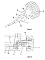
- the transmission mechanism illustrated by the figure 1 has two rods 1a, 1b of parallel axes.
- One end of the rod 1a is integral with a central core of a drive ring 2 intended to be located outside a watch case (not shown in this figure).
- the other end of this rod 1a is integral with a sliding member 3, engaged in a slide 4 formed on one side of a connecting member 5 and extending perpendicularly to the axis of the rod 1a.
- the end of the rod 1b, adjacent to the rod 1a, is integral with a sliding element 6 engaged in a slide 7 formed on another face of the connecting member 5 and extending also perpendicularly to the axis of the rod 1b.
- the two rods 1a, 1b being parallel, the two slides 4 and 7 are so too.
- the orientations of these slides 4 and 7 are perpendicular to each other.
- the straight sections of the sliding elements are complementary to the straight sections of the respective slides.
- the two slides 4 and 7 of the connecting member 5 allow a transmission of homokinetic rotational movements between the two parallel rods 1a, 1b.
- the tests carried out showed that this transmission was carried out without noise and without jerk and allowed to transmit a relatively large torque such as that necessary for the winding of a mainspring. These tests have shown that it is possible to transmit a rotation between two parallel rods axially offset by more than one millimeter from one another, without encountering any problem.
- the same mechanism can also transmit a rotation between two parallel rods having a much lower axial offset.
- the sectional view of the figure 2 illustrates an embodiment of this mechanism mounted on the one hand on a plate 10, the only element represented by a watch movement housed in a watch case of which only the middle part 8 has been shown, on the other hand through the middle 8.
- the rod 1a integral with the drive ring 2 is mounted in a tube 11 screwed into a passage through the middle part 8, while the rod 1b is mounted in a passage 9 of the plate 10.
- the sliding member 3 is integral with the rod 1a which is screwed into the central core 2a of the ring 2 from inside the middle part 8.
- the connecting member 5 is introduced since the opening of the middle side bottom, by successively engaging the sliding elements 3 and 6 in the respective slides 4 and 7.
- the variant illustrated by the figure 3 has been designed to allow the assembly of the transmission mechanism to through the passage in the middle 8 for the control rod. This variant reduces the diameter of the opening of the middle part of the bottom, because the connecting member 5 is no longer mounted through this opening.
- the outer end of the tube 11 ' has an external toothing 11'a and the ring 2' an internal toothing 2'b.
- the teeth 11'a and 2'b may be replaced by polygonal sections or any other non-circular complementary sections adapted to secure the ring 2 'and the tube 11' in rotation.
- the rod 1a, 1b is at three axial positions.
- the ring 2 ' is placed in the tube 11' so that its toothing 2'b is in engagement with the toothing 11'a of the tube 11 '.
- the connecting member 5 is mounted by engaging the sliding element 3 in the slide 4 and the sliding element 6 of the rod 1b is introduced into the slide 7.
- This assembly is then introduced through the lateral opening through the wall of the caseband 8 and the tube 11 'is screwed into the caseband 8 by driving it through the ring 2' whose teeth 2'b are in engagement with the toothing 11'a of the tube 11 '.
- the tube 11 ' is screwed, it pushes the crown 2' towards the center of the movement and blocks the axial position of the assembly, for example by screwing the zipper (not shown), or using a pin spring mounted on the zipper, as is traditionally done in watches, to engage the pull tab in a groove 12 of the rod 1b to make it integral with the zipper.
- the rods 1a, 1b have the same function as a conventional winding rod with two axial positions, one winding, the other time setting.
- This variant presents a difficulty in maintaining the toothing 2'b of the ring gear 2 'in engagement with the toothing 11'a of the tube 11', during the assembly of the transmission mechanism and intended to allow the screwing of this tube 11 ' .
- the outer end of the tube 11 has a conical recess 11" b, while an annular clearance 13 is provided between the central core 2 "of the ring 2" and the rod 1 "a.
- O-ring 14 is housed partly in the annular clearance 13, partly in the conical recess 11 “b, holding the ring 2" in the axial position in which its toothing 11 "a is engaged with the toothing 2" b of the crown 2 "as illustrated by the figure 4a .
- the tube 11 * has an internal thread 11 * c and the base of the central core of the crown 2 * comprises a thread 2 * c intended to be screwed into the thread 11 * c of the tube 11 *, as illustrated by the figure 5 .
- a ring 16 whose cross section of the opening is non-circular, is fixed to the base of the axial housing 2 * d formed in the central core 2 * a of the ring 2 * in which the rod 1 * is housed.
- the rod 1 * has a portion 17 whose cross section is complementary to that of the opening of the ring 16.
- This rod 1 * a further comprises a stop 18 which serves to support a spring 19, compressed between this stop 18 and the bottom of the housing 2 * d.
- This stop 18 also serves to limit the relative axial displacement between the ring 2 * and the rod 1 * a when the ring is unscrewed. As illustrated by figure 6 in this position, the stop 18 bears against the ring 16.
- the mechanism for transmitting movements between two rods of parallel axes is particularly simple and compact. Unlike mechanisms using gears, the same mechanism can be used for different spacings between the parallel axes of the rods 1a, 1b. It requires in all only two or three additional pieces compared to a conventional winding mechanism, namely a second rod and a connecting member, optionally a separate sliding element 3 *, as in the embodiment of the invention. Figures 5 and 6 to allow the fixing of the ring 16 after the introduction of the spring 19 and the rod 1 * a.
Abstract
Description
La présente invention se rapporte à une pièce d'horlogerie comprenant un boîtier renfermant un mouvement d'horlogerie, un mécanisme de transmission de mouvements de rotation homocinétiques entre deux tiges d'axes sensiblement parallèles, reliant l'extérieur du boîtier au mouvement d'horlogerie à travers un passage du boîtier.The present invention relates to a timepiece comprising a housing enclosing a clockwork movement, a mechanism for transmitting homokinetic rotational movements between two rods of substantially parallel axes, connecting the outside of the case to the watch movement. through a passage of the housing.
Il existe différentes raisons pour lesquelles une tige d'un mécanisme de transmission de mouvement de rotation peut se situer dans une position trop décentrée par rapport à la partie latérale de la boîte de montre. Différentes solutions ont été proposées pour éviter ce décentrage qui en plus d'être inesthétique, peut être gênant.There are various reasons why a rod of a rotational movement transmitting mechanism may be located in a position too off-center with respect to the side portion of the watch case. Different solutions have been proposed to avoid this decentering which in addition to being unsightly, can be embarrassing.
Parmi les solutions proposées on peut citer le
On a déjà proposé de réaliser des tiges de remontoir en deux parties dans le
Le but de la présente invention est de remédier, au moins en partie, aux inconvénients susmentionnés.The object of the present invention is to overcome, at least in part, the aforementioned drawbacks.
A cet effet, la présente invention a pour objet une pièce d'horlogerie selon la revendication 1.For this purpose, the present invention relates to a timepiece according to
De préférence, dans cette pièce d'horlogerie, les sections droites complémentaires respectives des éléments de coulissement et des coulisses présentent des parties rétrécies, ne permettant l'engagement et le dégagement mutuel des éléments de coulissement et des coulisses respectives que par déplacements selon les plans de coulissement respectifs, de manière qu'une fois les éléments de coulissement et les coulisses respectives engagés les uns dans les autres, les deux tiges sont solidaires l'une de l'autre en translation axiale.Preferably, in this timepiece, the respective complementary straight sections of the sliding elements and the slides have narrowed parts, allowing engagement and mutual clearance of the sliding elements and the respective slides only by displacements according to the plans. respective sliding members, so that once the sliding elements and the respective slides engaged in each other, the two rods are integral with each other in axial translation.
Les dessins annexés illustrent, schématiquement et à titre d'exemple, une forme d'exécution et différentes variantes de la pièce d'horlogerie objet de l'invention.
- La
figure 1 est une vue en perspective montrant le principe de fonctionnement du mécanisme de transmission de mouvement de rotation de la pièce d'horlogerie objet de l'invention; - la
figure 2 est une vue partielle en coupe d'une pièce d'horlogerie munie de ce mécanisme de transmission; - la
figure 3 est une vue partielle en coupe semblable à lafigure 2 d'une variante du mécanisme de transmission, correspondant à une coupe selon le plan vertical du mécanisme de lafigure 1 ; - les
figures 4a ,4b et 4c sont des vues en coupes d'une autre variante du mécanisme de transmission illustrant différentes phases de son montage; - la
figure 5 est une vue partielle en coupe d'une variante dans laquelle la couronne solidaire de la tige de commande est vissée sur la boîte de montre en position de repos; - la
figure 6 est une vue semblable à celle de lafigure 5 montrant la couronne en position dévissée.
- The
figure 1 is a perspective view showing the principle of operation of the rotational movement transmission mechanism of the timepiece object of the invention; - the
figure 2 is a partial sectional view of a timepiece provided with this transmission mechanism; - the
figure 3 is a partial sectional view similar to thefigure 2 of a variant of the transmission mechanism, corresponding to a section along the vertical plane of the mechanism of thefigure 1 ; - the
Figures 4a ,4b and 4c are sectional views of another variant of the transmission mechanism illustrating different phases of its assembly; - the
figure 5 is a partial sectional view of a variant in which the integral crown of the stem of control is screwed on the watch case in the rest position; - the
figure 6 is a view similar to that of thefigure 5 showing the crown in the unscrewed position.
Le mécanisme de transmission illustré par la
L'extrémité de la tige 1b, adjacente à la tige 1a, est solidaire d'un élément de coulissement 6 engagé dans une coulisse 7 ménagée sur une autre face de l'organe de liaison 5 et s'étendant aussi perpendiculairement à l'axe de la tige 1b. Les deux tiges 1a, 1b étant parallèles, les deux coulisses 4 et 7 le sont donc aussi. Par contre, les orientations de ces coulisses 4 et 7 sont perpendiculaires l'une par rapport à l'autre. Pour assurer le coulissement des éléments de coulissement et des coulisses respectives, les sections droites des éléments de coulissement sont complémentaires des sections droites des coulisses respectives.The end of the
Comme on le voit particulièrement bien en ce qui concerne l'élément de coulissement 6 et la coulisse 7, mais ceci étant aussi le cas de l'élément de coulissement 3 et de la coulisse 4, de préférence leurs sections droites présentent des parties rétrécies, ces sections étant ici en forme de T, ne permettant l'engagement et le dégagement mutuel des éléments de coulissement et des coulisses respectives que par déplacements selon les plans de coulissement respectifs, de manière qu'une fois les éléments de coulissement et les coulisses respectives engagés les uns dans les autres, les deux tiges sont aussi solidaires l'une de l'autre en translation axiale.As can be seen particularly with regard to the
Les deux coulisses 4 et 7 de l'organe de liaison 5 permettent une transmission des mouvements de rotation homocinétiques entre les deux tiges parallèles 1a, 1b. Les essais réalisés ont montré que cette transmission s'effectuait sans bruit et sans à-coup et permettait de transmettre un couple relativement important tel que celui nécessaire au remontage d'un ressort de barillet. Ces essais ont montré qu'il était possible de transmettre une rotation entre deux tiges parallèles décalées axialement de plus d'un millimètre l'une de l'autre, sans rencontrer aucun problème. Le même mécanisme peut tout aussi bien transmettre une rotation entre deux tiges parallèles ayant un décalage axial beaucoup plus faible.The two
La vue en coupe de la
Dans cette forme d'exécution, l'élément de coulissement 3 est solidaire de la tige 1a qui est vissée dans le noyau central 2a de la couronne 2 depuis l'intérieur de la carrure 8. Ensuite, l'organe de liaison 5 est introduit depuis l'ouverture de la carrure côté fond, en engageant successivement les éléments de coulissement 3 et 6 dans les coulisses respectives 4 et 7.In this embodiment, the
La variante illustrée par la
A cet effet, l'extrémité externe du tube 11' présente une denture externe 11'a et la couronne 2' une denture interne 2'b. Les dentures 11'a et 2'b peuvent être remplacées par des sections polygonales ou toutes autres sections complémentaires non circulaires aptes à solidariser la couronne 2' et le tube 11' en rotation. La tige 1a, 1b est à trois positions axiales. Pour le montage du mécanisme de transmission, on place la couronne 2' dans le tube 11' de manière que sa denture 2'b soit en prise avec la denture 11'a du tube 11'. On monte l'organe de liaison 5 en engageant l'élément de coulissement 3 dans la coulisse 4 et on introduit l'élément de coulissement 6 de la tige 1b dans la coulisse 7.For this purpose, the outer end of the tube 11 'has an external toothing 11'a and the ring 2' an internal toothing 2'b. The teeth 11'a and 2'b may be replaced by polygonal sections or any other non-circular complementary sections adapted to secure the ring 2 'and the tube 11' in rotation. The
On introduit ensuite cet ensemble à travers l'ouverture latérale traversant la paroi de la carrure 8 et on visse le tube 11' dans la carrure 8 en l'entraînant par la couronne 2' dont la denture 2'b est en prise avec la denture 11'a du tube 11'. Une fois le tube 11' vissé, on pousse la couronne 2' vers le centre du mouvement et on bloque la position axiale de l'ensemble, par exemple en vissant la tirette (non représentée), ou à l'aide d'une goupille montée à ressort sur la tirette, comme ceci se fait traditionnellement dans les montres, pour engager le plot de tirette dans une gorge 12 de la tige 1b afin de la rendre solidaire de la tirette. Une fois cette opération terminée, les tiges 1a, 1b ont la même fonction qu'une tige de remontoir classique à deux positions axiales, l'une de remontage, l'autre de mise à l'heure.This assembly is then introduced through the lateral opening through the wall of the
Cette variante présente une difficulté quant au maintien de la denture 2'b de la couronne 2' en prise avec la denture 11'a du tube 11', lors du montage du mécanisme de transmission et destiné à permettre le vissage de ce tube 11'.This variant presents a difficulty in maintaining the toothing 2'b of the ring gear 2 'in engagement with the toothing 11'a of the tube 11', during the assembly of the transmission mechanism and intended to allow the screwing of this tube 11 ' .
La variante illustrée par les
A cet effet, l'extrémité externe du tube 11" présente un évidement conique 11"b, alors qu'un dégagement annulaire 13 est ménagé entre le noyau central 2"a de la couronne 2" et la tige 1"a. Un joint torique 14 est logé en partie dans le dégagement annulaire 13, en partie dans l'évidement conique 11"b, retenant la couronne 2" dans la position axiale dans laquelle sa denture 11"a est en prise avec la denture 2"b de la couronne 2", comme illustré par la
Ce positionnement facilite sensiblement le vissage du tube 11". Une fois le tube 11" vissé, on pousse légèrement la couronne vers le centre de la montre pour permettre de visser la tirette comme expliqué précédemment. En poussant la couronne 2", on comprime le joint torique 14 en l'introduisant dans la partie cylindrique du tube 11" adjacente à la petite base de l'évidement conique 11"b, de sorte que le joint 14 sert alors de joint d'étanchéité.This positioning substantially facilitates the screwing of the
La variante illustrée par les
A cet effet, le tube 11* comporte un filetage interne 11*c et la base du noyau central de la couronne 2* comporte un filetage 2*c destiné à se visser dans le filetage 11*c du tube 11*, comme illustré par la
Pendant ce vissage de la couronne 2*, il faut débrayer la couronne 2* de la tige 1*a. Pour obtenir ce débrayage, une bague 16, dont la section droite de l'ouverture est non circulaire, est fixée à la base du logement axial 2*d ménagé dans le noyau central 2*a de la couronne 2* dans lequel la tige 1*a est logée. De son côté, la tige 1*a comporte une partie 17 dont la section droite est complémentaire de celle de l'ouverture de la bague 16. Cette tige 1*a comporte encore une butée 18 qui sert d'appui à un ressort 19, comprimé entre cette butée 18 et le fond du logement 2*d. Cette butée 18 sert également à limiter le déplacement axial relatif entre la couronne 2* et la tige 1*a lorsque la couronne est dévissée. Comme illustré par la
Comme on peut le constater de la description qui précède, le mécanisme de transmission de mouvements entre deux tiges d'axes parallèles est particulièrement simple et peu encombrant. Contrairement aux mécanismes utilisant des engrenages, le même mécanisme peut être utilisé pour différents écartements entre les axes parallèles des tiges 1a, 1b. Il ne nécessite en tout que deux, voire trois pièces supplémentaires par rapport à un mécanisme de remontoir classique, à savoir une seconde tige et un organe de liaison, éventuellement un élément de coulissement 3* séparé, comme dans la forme d'exécution des
Claims (5)
Priority Applications (5)
| Application Number | Priority Date | Filing Date | Title |
|---|---|---|---|
| AT09405115T ATE539388T1 (en) | 2009-07-16 | 2009-07-16 | CLOCK |
| EP09405115A EP2275883B1 (en) | 2009-07-16 | 2009-07-16 | Timepiece |
| US12/824,667 US8282271B2 (en) | 2009-07-16 | 2010-06-28 | Timepiece |
| JP2010160628A JP5596448B2 (en) | 2009-07-16 | 2010-07-15 | clock |
| CN2010102321691A CN101957587B (en) | 2009-07-16 | 2010-07-15 | Timepiece |
Applications Claiming Priority (1)
| Application Number | Priority Date | Filing Date | Title |
|---|---|---|---|
| EP09405115A EP2275883B1 (en) | 2009-07-16 | 2009-07-16 | Timepiece |
Publications (2)
| Publication Number | Publication Date |
|---|---|
| EP2275883A1 true EP2275883A1 (en) | 2011-01-19 |
| EP2275883B1 EP2275883B1 (en) | 2011-12-28 |
Family
ID=41394843
Family Applications (1)
| Application Number | Title | Priority Date | Filing Date |
|---|---|---|---|
| EP09405115A Active EP2275883B1 (en) | 2009-07-16 | 2009-07-16 | Timepiece |
Country Status (5)
| Country | Link |
|---|---|
| US (1) | US8282271B2 (en) |
| EP (1) | EP2275883B1 (en) |
| JP (1) | JP5596448B2 (en) |
| CN (1) | CN101957587B (en) |
| AT (1) | ATE539388T1 (en) |
Cited By (4)
| Publication number | Priority date | Publication date | Assignee | Title |
|---|---|---|---|---|
| EP3425227A1 (en) | 2017-07-06 | 2019-01-09 | Rolex Sa | Clock transmission joint |
| EP3425226A1 (en) | 2017-07-06 | 2019-01-09 | Rolex Sa | Clock transmission joint |
| EP3825778A1 (en) * | 2019-11-21 | 2021-05-26 | The Swatch Group Research and Development Ltd | Control crown for a timepiece |
| US11409243B2 (en) | 2017-07-06 | 2022-08-09 | Rolex Sa | Timepiece transmission coupling |
Families Citing this family (5)
| Publication number | Priority date | Publication date | Assignee | Title |
|---|---|---|---|---|
| EP2365407B1 (en) * | 2010-03-08 | 2017-06-28 | Montres Breguet SA | Device for actuating the winding-up and the time setting of a clockwork |
| EP2600214B1 (en) * | 2011-12-01 | 2015-01-28 | Agenhor SA | Transmission mechanism between two portions of a control rod for a clock movement |
| US9086717B2 (en) | 2012-02-13 | 2015-07-21 | Invicta Watch Company Of America, Inc. | Interface for actuating a device |
| CN104698811B (en) * | 2015-03-24 | 2017-04-26 | 惠州Tcl移动通信有限公司 | Watchcase assembly and watch |
| CN106502077A (en) * | 2016-12-09 | 2017-03-15 | 陈红 | Full-time zone wrist-watch |
Citations (8)
| Publication number | Priority date | Publication date | Assignee | Title |
|---|---|---|---|---|
| CH36526A (en) * | 1906-06-21 | 1907-01-31 | Karl Brunner Johann | Winding shaft for pocket watches |
| CH486728A (en) | 1967-08-16 | 1969-09-15 | Piquerez Sa Ervin | Timepiece comprising two rotating bezels |
| FR2059626A1 (en) * | 1969-08-22 | 1971-06-04 | Meyer & Co Ag | |
| US3690061A (en) | 1969-12-05 | 1972-09-12 | Omega Brandt & Freres Sa Louis | Watch having a two-piece winding stem |
| JPS5494348U (en) * | 1977-12-16 | 1979-07-04 | ||
| CH691632A5 (en) | 1997-06-18 | 2001-08-31 | Chopard Internat S A | Watch winding stem and setting the time into two parts. |
| EP1134628A1 (en) | 2000-03-17 | 2001-09-19 | Dubois & Depraz S.A. | Transmission mechanism for axial and rotational motion between two off-set axes |
| DE202004001124U1 (en) | 2003-01-27 | 2004-06-24 | Tag Heuer S.A., Marin | Clock mechanism with base module and auxiliary module has base, auxiliary clock mechanisms with pointers, pull-out and/or time setting shafts operated axially and/or rotationally by single watch crown |
Family Cites Families (5)
| Publication number | Priority date | Publication date | Assignee | Title |
|---|---|---|---|---|
| FR1134628A (en) | 1955-11-03 | 1957-04-15 | Clamp for props or similar applications and method of manufacture thereof | |
| EP1580626A1 (en) * | 2004-03-24 | 2005-09-28 | Blancpain S.A. | Correction mechanism for a timepiece |
| DE602005014468D1 (en) * | 2005-07-26 | 2009-06-25 | Montres Breguet Sa | Device with spindle for mounting and timing of watches |
| JP4937013B2 (en) * | 2007-06-28 | 2012-05-23 | セイコーインスツル株式会社 | Manufacturing method of crown provided in portable watch |
| ATE469380T1 (en) * | 2007-08-30 | 2010-06-15 | Eta Sa Mft Horlogere Suisse | WATCH EQUIPPED WITH A FUNCTION DISPLAY |
-
2009
- 2009-07-16 EP EP09405115A patent/EP2275883B1/en active Active
- 2009-07-16 AT AT09405115T patent/ATE539388T1/en active
-
2010
- 2010-06-28 US US12/824,667 patent/US8282271B2/en active Active
- 2010-07-15 CN CN2010102321691A patent/CN101957587B/en active Active
- 2010-07-15 JP JP2010160628A patent/JP5596448B2/en active Active
Patent Citations (8)
| Publication number | Priority date | Publication date | Assignee | Title |
|---|---|---|---|---|
| CH36526A (en) * | 1906-06-21 | 1907-01-31 | Karl Brunner Johann | Winding shaft for pocket watches |
| CH486728A (en) | 1967-08-16 | 1969-09-15 | Piquerez Sa Ervin | Timepiece comprising two rotating bezels |
| FR2059626A1 (en) * | 1969-08-22 | 1971-06-04 | Meyer & Co Ag | |
| US3690061A (en) | 1969-12-05 | 1972-09-12 | Omega Brandt & Freres Sa Louis | Watch having a two-piece winding stem |
| JPS5494348U (en) * | 1977-12-16 | 1979-07-04 | ||
| CH691632A5 (en) | 1997-06-18 | 2001-08-31 | Chopard Internat S A | Watch winding stem and setting the time into two parts. |
| EP1134628A1 (en) | 2000-03-17 | 2001-09-19 | Dubois & Depraz S.A. | Transmission mechanism for axial and rotational motion between two off-set axes |
| DE202004001124U1 (en) | 2003-01-27 | 2004-06-24 | Tag Heuer S.A., Marin | Clock mechanism with base module and auxiliary module has base, auxiliary clock mechanisms with pointers, pull-out and/or time setting shafts operated axially and/or rotationally by single watch crown |
Cited By (5)
| Publication number | Priority date | Publication date | Assignee | Title |
|---|---|---|---|---|
| EP3425227A1 (en) | 2017-07-06 | 2019-01-09 | Rolex Sa | Clock transmission joint |
| EP3425226A1 (en) | 2017-07-06 | 2019-01-09 | Rolex Sa | Clock transmission joint |
| US11409243B2 (en) | 2017-07-06 | 2022-08-09 | Rolex Sa | Timepiece transmission coupling |
| EP3825778A1 (en) * | 2019-11-21 | 2021-05-26 | The Swatch Group Research and Development Ltd | Control crown for a timepiece |
| US11243498B2 (en) | 2019-11-21 | 2022-02-08 | The Swatch Group Research And Development Ltd | Control crown for a timepiece |
Also Published As
| Publication number | Publication date |
|---|---|
| ATE539388T1 (en) | 2012-01-15 |
| JP5596448B2 (en) | 2014-09-24 |
| JP2011022144A (en) | 2011-02-03 |
| CN101957587A (en) | 2011-01-26 |
| EP2275883B1 (en) | 2011-12-28 |
| CN101957587B (en) | 2012-07-18 |
| US8282271B2 (en) | 2012-10-09 |
| US20110013496A1 (en) | 2011-01-20 |
Similar Documents
| Publication | Publication Date | Title |
|---|---|---|
| EP2275883B1 (en) | Timepiece | |
| EP2827202B1 (en) | Control device for a timepiece | |
| EP2859412B1 (en) | Rotating bezel system | |
| EP3756501B1 (en) | Fixing device for a bracelet | |
| EP2182417A2 (en) | Screw crown and method for orienting such a crown on a watch case | |
| EP2290477A1 (en) | Assembly for fixing the peripheral end of the hairspring of a device with balance wheel-hairspring for a timepiece | |
| EP1853977B1 (en) | Lockable push-piece | |
| EP1727005B1 (en) | Screwing crown and method to assembly such a crown on a watch case | |
| EP2469358B1 (en) | Mechanism for transmitting axial and rotary movements between two offset shafts | |
| EP2765463B1 (en) | Mechanism for transmitting axial and rotary movements between two offset staffs and timepiece comprising said mechanism | |
| EP3376308B1 (en) | Winding mechanism of a timepiece | |
| EP3825778B1 (en) | Control crown for a timepiece | |
| EP2915445B1 (en) | Device and method for assembling a pivot of at least two parts, corresponding set of two assembled parts | |
| EP3805874B1 (en) | Adjustable threaded crown | |
| CH716825A2 (en) | Control crown for a timepiece. | |
| EP3805871B1 (en) | Adjustable threaded crown | |
| EP2600214B1 (en) | Transmission mechanism between two portions of a control rod for a clock movement | |
| CH716682A2 (en) | Rotatable screw-down crown. | |
| CH717211B1 (en) | Crown for timepiece box, stem for watch movement and timepiece. | |
| EP4155834A1 (en) | Secure control element for a timepiece | |
| CH717111B1 (en) | Display correction mechanism and watch movement comprising this mechanism. | |
| CH719808A1 (en) | Control mechanism of a timepiece. | |
| CH719090B1 (en) | Control device for a timepiece. | |
| CH716681A2 (en) | Rotatable screw-down crown. | |
| CH719000A2 (en) | SECURE CONTROL DEVICE FOR A TIMEPIECE. |
Legal Events
| Date | Code | Title | Description |
|---|---|---|---|
| PUAI | Public reference made under article 153(3) epc to a published international application that has entered the european phase |
Free format text: ORIGINAL CODE: 0009012 |
|
| AK | Designated contracting states |
Kind code of ref document: A1 Designated state(s): AT BE BG CH CY CZ DE DK EE ES FI FR GB GR HR HU IE IS IT LI LT LU LV MC MK MT NL NO PL PT RO SE SI SK SM TR |
|
| AX | Request for extension of the european patent |
Extension state: AL BA RS |
|
| 17P | Request for examination filed |
Effective date: 20110430 |
|
| RIC1 | Information provided on ipc code assigned before grant |
Ipc: G04B 37/06 20060101AFI20110530BHEP |
|
| GRAP | Despatch of communication of intention to grant a patent |
Free format text: ORIGINAL CODE: EPIDOSNIGR1 |
|
| GRAS | Grant fee paid |
Free format text: ORIGINAL CODE: EPIDOSNIGR3 |
|
| GRAA | (expected) grant |
Free format text: ORIGINAL CODE: 0009210 |
|
| AK | Designated contracting states |
Kind code of ref document: B1 Designated state(s): AT BE BG CH CY CZ DE DK EE ES FI FR GB GR HR HU IE IS IT LI LT LU LV MC MK MT NL NO PL PT RO SE SI SK SM TR |
|
| REG | Reference to a national code |
Ref country code: GB Ref legal event code: FG4D Free format text: NOT ENGLISH |
|
| REG | Reference to a national code |
Ref country code: CH Ref legal event code: NV Representative=s name: MOINAS & SAVOYE SA Ref country code: CH Ref legal event code: EP |
|
| REG | Reference to a national code |
Ref country code: AT Ref legal event code: REF Ref document number: 539388 Country of ref document: AT Kind code of ref document: T Effective date: 20120115 |
|
| REG | Reference to a national code |
Ref country code: IE Ref legal event code: FG4D |
|
| REG | Reference to a national code |
Ref country code: DE Ref legal event code: R096 Ref document number: 602009004378 Country of ref document: DE Effective date: 20120315 |
|
| REG | Reference to a national code |
Ref country code: NL Ref legal event code: VDEP Effective date: 20111228 |
|
| PG25 | Lapsed in a contracting state [announced via postgrant information from national office to epo] |
Ref country code: NO Free format text: LAPSE BECAUSE OF FAILURE TO SUBMIT A TRANSLATION OF THE DESCRIPTION OR TO PAY THE FEE WITHIN THE PRESCRIBED TIME-LIMIT Effective date: 20120328 Ref country code: LT Free format text: LAPSE BECAUSE OF FAILURE TO SUBMIT A TRANSLATION OF THE DESCRIPTION OR TO PAY THE FEE WITHIN THE PRESCRIBED TIME-LIMIT Effective date: 20111228 |
|
| LTIE | Lt: invalidation of european patent or patent extension |
Effective date: 20111228 |
|
| PG25 | Lapsed in a contracting state [announced via postgrant information from national office to epo] |
Ref country code: SE Free format text: LAPSE BECAUSE OF FAILURE TO SUBMIT A TRANSLATION OF THE DESCRIPTION OR TO PAY THE FEE WITHIN THE PRESCRIBED TIME-LIMIT Effective date: 20111228 Ref country code: HR Free format text: LAPSE BECAUSE OF FAILURE TO SUBMIT A TRANSLATION OF THE DESCRIPTION OR TO PAY THE FEE WITHIN THE PRESCRIBED TIME-LIMIT Effective date: 20111228 Ref country code: SI Free format text: LAPSE BECAUSE OF FAILURE TO SUBMIT A TRANSLATION OF THE DESCRIPTION OR TO PAY THE FEE WITHIN THE PRESCRIBED TIME-LIMIT Effective date: 20111228 Ref country code: GR Free format text: LAPSE BECAUSE OF FAILURE TO SUBMIT A TRANSLATION OF THE DESCRIPTION OR TO PAY THE FEE WITHIN THE PRESCRIBED TIME-LIMIT Effective date: 20120329 Ref country code: LV Free format text: LAPSE BECAUSE OF FAILURE TO SUBMIT A TRANSLATION OF THE DESCRIPTION OR TO PAY THE FEE WITHIN THE PRESCRIBED TIME-LIMIT Effective date: 20111228 |
|
| PG25 | Lapsed in a contracting state [announced via postgrant information from national office to epo] |
Ref country code: CY Free format text: LAPSE BECAUSE OF FAILURE TO SUBMIT A TRANSLATION OF THE DESCRIPTION OR TO PAY THE FEE WITHIN THE PRESCRIBED TIME-LIMIT Effective date: 20111228 |
|
| REG | Reference to a national code |
Ref country code: IE Ref legal event code: FD4D |
|
| PG25 | Lapsed in a contracting state [announced via postgrant information from national office to epo] |
Ref country code: EE Free format text: LAPSE BECAUSE OF FAILURE TO SUBMIT A TRANSLATION OF THE DESCRIPTION OR TO PAY THE FEE WITHIN THE PRESCRIBED TIME-LIMIT Effective date: 20111228 Ref country code: SK Free format text: LAPSE BECAUSE OF FAILURE TO SUBMIT A TRANSLATION OF THE DESCRIPTION OR TO PAY THE FEE WITHIN THE PRESCRIBED TIME-LIMIT Effective date: 20111228 Ref country code: NL Free format text: LAPSE BECAUSE OF FAILURE TO SUBMIT A TRANSLATION OF THE DESCRIPTION OR TO PAY THE FEE WITHIN THE PRESCRIBED TIME-LIMIT Effective date: 20111228 Ref country code: IE Free format text: LAPSE BECAUSE OF FAILURE TO SUBMIT A TRANSLATION OF THE DESCRIPTION OR TO PAY THE FEE WITHIN THE PRESCRIBED TIME-LIMIT Effective date: 20111228 Ref country code: CZ Free format text: LAPSE BECAUSE OF FAILURE TO SUBMIT A TRANSLATION OF THE DESCRIPTION OR TO PAY THE FEE WITHIN THE PRESCRIBED TIME-LIMIT Effective date: 20111228 Ref country code: BG Free format text: LAPSE BECAUSE OF FAILURE TO SUBMIT A TRANSLATION OF THE DESCRIPTION OR TO PAY THE FEE WITHIN THE PRESCRIBED TIME-LIMIT Effective date: 20120328 Ref country code: IS Free format text: LAPSE BECAUSE OF FAILURE TO SUBMIT A TRANSLATION OF THE DESCRIPTION OR TO PAY THE FEE WITHIN THE PRESCRIBED TIME-LIMIT Effective date: 20120428 |
|
| PG25 | Lapsed in a contracting state [announced via postgrant information from national office to epo] |
Ref country code: PT Free format text: LAPSE BECAUSE OF FAILURE TO SUBMIT A TRANSLATION OF THE DESCRIPTION OR TO PAY THE FEE WITHIN THE PRESCRIBED TIME-LIMIT Effective date: 20120430 Ref country code: RO Free format text: LAPSE BECAUSE OF FAILURE TO SUBMIT A TRANSLATION OF THE DESCRIPTION OR TO PAY THE FEE WITHIN THE PRESCRIBED TIME-LIMIT Effective date: 20111228 Ref country code: PL Free format text: LAPSE BECAUSE OF FAILURE TO SUBMIT A TRANSLATION OF THE DESCRIPTION OR TO PAY THE FEE WITHIN THE PRESCRIBED TIME-LIMIT Effective date: 20111228 |
|
| REG | Reference to a national code |
Ref country code: AT Ref legal event code: MK05 Ref document number: 539388 Country of ref document: AT Kind code of ref document: T Effective date: 20111228 |
|
| PG25 | Lapsed in a contracting state [announced via postgrant information from national office to epo] |
Ref country code: DK Free format text: LAPSE BECAUSE OF FAILURE TO SUBMIT A TRANSLATION OF THE DESCRIPTION OR TO PAY THE FEE WITHIN THE PRESCRIBED TIME-LIMIT Effective date: 20111228 |
|
| PLBE | No opposition filed within time limit |
Free format text: ORIGINAL CODE: 0009261 |
|
| STAA | Information on the status of an ep patent application or granted ep patent |
Free format text: STATUS: NO OPPOSITION FILED WITHIN TIME LIMIT |
|
| PG25 | Lapsed in a contracting state [announced via postgrant information from national office to epo] |
Ref country code: IT Free format text: LAPSE BECAUSE OF FAILURE TO SUBMIT A TRANSLATION OF THE DESCRIPTION OR TO PAY THE FEE WITHIN THE PRESCRIBED TIME-LIMIT Effective date: 20111228 |
|
| 26N | No opposition filed |
Effective date: 20121001 |
|
| REG | Reference to a national code |
Ref country code: DE Ref legal event code: R097 Ref document number: 602009004378 Country of ref document: DE Effective date: 20121001 |
|
| BERE | Be: lapsed |
Owner name: ROLEX SA Effective date: 20120731 |
|
| PG25 | Lapsed in a contracting state [announced via postgrant information from national office to epo] |
Ref country code: AT Free format text: LAPSE BECAUSE OF FAILURE TO SUBMIT A TRANSLATION OF THE DESCRIPTION OR TO PAY THE FEE WITHIN THE PRESCRIBED TIME-LIMIT Effective date: 20111228 |
|
| PG25 | Lapsed in a contracting state [announced via postgrant information from national office to epo] |
Ref country code: MK Free format text: LAPSE BECAUSE OF FAILURE TO SUBMIT A TRANSLATION OF THE DESCRIPTION OR TO PAY THE FEE WITHIN THE PRESCRIBED TIME-LIMIT Effective date: 20111228 Ref country code: MC Free format text: LAPSE BECAUSE OF NON-PAYMENT OF DUE FEES Effective date: 20120731 |
|
| PG25 | Lapsed in a contracting state [announced via postgrant information from national office to epo] |
Ref country code: ES Free format text: LAPSE BECAUSE OF FAILURE TO SUBMIT A TRANSLATION OF THE DESCRIPTION OR TO PAY THE FEE WITHIN THE PRESCRIBED TIME-LIMIT Effective date: 20120408 |
|
| PG25 | Lapsed in a contracting state [announced via postgrant information from national office to epo] |
Ref country code: BE Free format text: LAPSE BECAUSE OF NON-PAYMENT OF DUE FEES Effective date: 20120731 |
|
| PG25 | Lapsed in a contracting state [announced via postgrant information from national office to epo] |
Ref country code: FI Free format text: LAPSE BECAUSE OF FAILURE TO SUBMIT A TRANSLATION OF THE DESCRIPTION OR TO PAY THE FEE WITHIN THE PRESCRIBED TIME-LIMIT Effective date: 20111228 |
|
| PG25 | Lapsed in a contracting state [announced via postgrant information from national office to epo] |
Ref country code: MT Free format text: LAPSE BECAUSE OF FAILURE TO SUBMIT A TRANSLATION OF THE DESCRIPTION OR TO PAY THE FEE WITHIN THE PRESCRIBED TIME-LIMIT Effective date: 20111228 |
|
| PG25 | Lapsed in a contracting state [announced via postgrant information from national office to epo] |
Ref country code: TR Free format text: LAPSE BECAUSE OF FAILURE TO SUBMIT A TRANSLATION OF THE DESCRIPTION OR TO PAY THE FEE WITHIN THE PRESCRIBED TIME-LIMIT Effective date: 20111228 |
|
| PG25 | Lapsed in a contracting state [announced via postgrant information from national office to epo] |
Ref country code: LU Free format text: LAPSE BECAUSE OF NON-PAYMENT OF DUE FEES Effective date: 20120716 Ref country code: SM Free format text: LAPSE BECAUSE OF FAILURE TO SUBMIT A TRANSLATION OF THE DESCRIPTION OR TO PAY THE FEE WITHIN THE PRESCRIBED TIME-LIMIT Effective date: 20111228 |
|
| PG25 | Lapsed in a contracting state [announced via postgrant information from national office to epo] |
Ref country code: HU Free format text: LAPSE BECAUSE OF FAILURE TO SUBMIT A TRANSLATION OF THE DESCRIPTION OR TO PAY THE FEE WITHIN THE PRESCRIBED TIME-LIMIT Effective date: 20090716 |
|
| REG | Reference to a national code |
Ref country code: FR Ref legal event code: PLFP Year of fee payment: 8 |
|
| REG | Reference to a national code |
Ref country code: CH Ref legal event code: PFA Owner name: ROLEX SA, CH Free format text: FORMER OWNER: ROLEX SA, CH |
|
| REG | Reference to a national code |
Ref country code: FR Ref legal event code: PLFP Year of fee payment: 9 |
|
| REG | Reference to a national code |
Ref country code: FR Ref legal event code: PLFP Year of fee payment: 10 |
|
| P01 | Opt-out of the competence of the unified patent court (upc) registered |
Effective date: 20230528 |
|
| PGFP | Annual fee paid to national office [announced via postgrant information from national office to epo] |
Ref country code: GB Payment date: 20230725 Year of fee payment: 15 Ref country code: CH Payment date: 20230802 Year of fee payment: 15 |
|
| PGFP | Annual fee paid to national office [announced via postgrant information from national office to epo] |
Ref country code: FR Payment date: 20230727 Year of fee payment: 15 Ref country code: DE Payment date: 20230712 Year of fee payment: 15 |