EP2275748B1 - Verfahren zum Betrieb einer Heizungsanlage sowie Heizungsanlage - Google Patents
Verfahren zum Betrieb einer Heizungsanlage sowie Heizungsanlage Download PDFInfo
- Publication number
- EP2275748B1 EP2275748B1 EP10169694.6A EP10169694A EP2275748B1 EP 2275748 B1 EP2275748 B1 EP 2275748B1 EP 10169694 A EP10169694 A EP 10169694A EP 2275748 B1 EP2275748 B1 EP 2275748B1
- Authority
- EP
- European Patent Office
- Prior art keywords
- heating medium
- rla
- awt
- connector
- section
- Prior art date
- Legal status (The legal status is an assumption and is not a legal conclusion. Google has not performed a legal analysis and makes no representation as to the accuracy of the status listed.)
- Active
Links
Images


Classifications
-
- F—MECHANICAL ENGINEERING; LIGHTING; HEATING; WEAPONS; BLASTING
- F24—HEATING; RANGES; VENTILATING
- F24D—DOMESTIC- OR SPACE-HEATING SYSTEMS, e.g. CENTRAL HEATING SYSTEMS; DOMESTIC HOT-WATER SUPPLY SYSTEMS; ELEMENTS OR COMPONENTS THEREFOR
- F24D12/00—Other central heating systems
- F24D12/02—Other central heating systems having more than one heat source
-
- F—MECHANICAL ENGINEERING; LIGHTING; HEATING; WEAPONS; BLASTING
- F24—HEATING; RANGES; VENTILATING
- F24D—DOMESTIC- OR SPACE-HEATING SYSTEMS, e.g. CENTRAL HEATING SYSTEMS; DOMESTIC HOT-WATER SUPPLY SYSTEMS; ELEMENTS OR COMPONENTS THEREFOR
- F24D11/00—Central heating systems using heat accumulated in storage masses
- F24D11/002—Central heating systems using heat accumulated in storage masses water heating system
- F24D11/004—Central heating systems using heat accumulated in storage masses water heating system with conventional supplementary heat source
-
- F—MECHANICAL ENGINEERING; LIGHTING; HEATING; WEAPONS; BLASTING
- F24—HEATING; RANGES; VENTILATING
- F24D—DOMESTIC- OR SPACE-HEATING SYSTEMS, e.g. CENTRAL HEATING SYSTEMS; DOMESTIC HOT-WATER SUPPLY SYSTEMS; ELEMENTS OR COMPONENTS THEREFOR
- F24D11/00—Central heating systems using heat accumulated in storage masses
- F24D11/002—Central heating systems using heat accumulated in storage masses water heating system
- F24D11/005—Central heating systems using heat accumulated in storage masses water heating system with recuperation of waste heat
-
- F—MECHANICAL ENGINEERING; LIGHTING; HEATING; WEAPONS; BLASTING
- F24—HEATING; RANGES; VENTILATING
- F24D—DOMESTIC- OR SPACE-HEATING SYSTEMS, e.g. CENTRAL HEATING SYSTEMS; DOMESTIC HOT-WATER SUPPLY SYSTEMS; ELEMENTS OR COMPONENTS THEREFOR
- F24D19/00—Details
- F24D19/10—Arrangement or mounting of control or safety devices
- F24D19/1006—Arrangement or mounting of control or safety devices for water heating systems
- F24D19/1009—Arrangement or mounting of control or safety devices for water heating systems for central heating
- F24D19/1015—Arrangement or mounting of control or safety devices for water heating systems for central heating using a valve or valves
- F24D19/1024—Arrangement or mounting of control or safety devices for water heating systems for central heating using a valve or valves a multiple way valve
-
- F—MECHANICAL ENGINEERING; LIGHTING; HEATING; WEAPONS; BLASTING
- F24—HEATING; RANGES; VENTILATING
- F24D—DOMESTIC- OR SPACE-HEATING SYSTEMS, e.g. CENTRAL HEATING SYSTEMS; DOMESTIC HOT-WATER SUPPLY SYSTEMS; ELEMENTS OR COMPONENTS THEREFOR
- F24D2200/00—Heat sources or energy sources
- F24D2200/04—Gas or oil fired boiler
-
- F—MECHANICAL ENGINEERING; LIGHTING; HEATING; WEAPONS; BLASTING
- F24—HEATING; RANGES; VENTILATING
- F24D—DOMESTIC- OR SPACE-HEATING SYSTEMS, e.g. CENTRAL HEATING SYSTEMS; DOMESTIC HOT-WATER SUPPLY SYSTEMS; ELEMENTS OR COMPONENTS THEREFOR
- F24D2200/00—Heat sources or energy sources
- F24D2200/16—Waste heat
- F24D2200/18—Flue gas recuperation
-
- F—MECHANICAL ENGINEERING; LIGHTING; HEATING; WEAPONS; BLASTING
- F24—HEATING; RANGES; VENTILATING
- F24D—DOMESTIC- OR SPACE-HEATING SYSTEMS, e.g. CENTRAL HEATING SYSTEMS; DOMESTIC HOT-WATER SUPPLY SYSTEMS; ELEMENTS OR COMPONENTS THEREFOR
- F24D2220/00—Components of central heating installations excluding heat sources
- F24D2220/02—Fluid distribution means
- F24D2220/0214—Inlets or outlets
-
- F—MECHANICAL ENGINEERING; LIGHTING; HEATING; WEAPONS; BLASTING
- F24—HEATING; RANGES; VENTILATING
- F24D—DOMESTIC- OR SPACE-HEATING SYSTEMS, e.g. CENTRAL HEATING SYSTEMS; DOMESTIC HOT-WATER SUPPLY SYSTEMS; ELEMENTS OR COMPONENTS THEREFOR
- F24D2220/00—Components of central heating installations excluding heat sources
- F24D2220/08—Storage tanks
-
- Y—GENERAL TAGGING OF NEW TECHNOLOGICAL DEVELOPMENTS; GENERAL TAGGING OF CROSS-SECTIONAL TECHNOLOGIES SPANNING OVER SEVERAL SECTIONS OF THE IPC; TECHNICAL SUBJECTS COVERED BY FORMER USPC CROSS-REFERENCE ART COLLECTIONS [XRACs] AND DIGESTS
- Y02—TECHNOLOGIES OR APPLICATIONS FOR MITIGATION OR ADAPTATION AGAINST CLIMATE CHANGE
- Y02B—CLIMATE CHANGE MITIGATION TECHNOLOGIES RELATED TO BUILDINGS, e.g. HOUSING, HOUSE APPLIANCES OR RELATED END-USER APPLICATIONS
- Y02B10/00—Integration of renewable energy sources in buildings
- Y02B10/70—Hybrid systems, e.g. uninterruptible or back-up power supplies integrating renewable energies
-
- Y—GENERAL TAGGING OF NEW TECHNOLOGICAL DEVELOPMENTS; GENERAL TAGGING OF CROSS-SECTIONAL TECHNOLOGIES SPANNING OVER SEVERAL SECTIONS OF THE IPC; TECHNICAL SUBJECTS COVERED BY FORMER USPC CROSS-REFERENCE ART COLLECTIONS [XRACs] AND DIGESTS
- Y02—TECHNOLOGIES OR APPLICATIONS FOR MITIGATION OR ADAPTATION AGAINST CLIMATE CHANGE
- Y02B—CLIMATE CHANGE MITIGATION TECHNOLOGIES RELATED TO BUILDINGS, e.g. HOUSING, HOUSE APPLIANCES OR RELATED END-USER APPLICATIONS
- Y02B30/00—Energy efficient heating, ventilation or air conditioning [HVAC]
Definitions
- the invention relates to a method for operating a heating system according to the preamble of claim 1 and a heating system according to the preamble of claim 4.
- RLA return flow increase
- Such heat generators are very often combined with storage tanks in which the heat generated is stored until it is used.
- the upper part of the buffer in the shortest possible time must be brought to the highest possible temperature, rather than a large amount of heat transport and storage medium, which is usually water to heat only moderately.
- This objective is achieved with various methods and devices whose functions are to first supply warmer water from a central port of the buffer to the RLA before accessing the coldest water of a lowermost port.
- the known devices include, for example, a starting relief with three-way switching valve and storage sensor, a three-way mixing valve with a second control circuit and flow sensor, a three-way mixing valve with a control loop and sequential circuit, a multi-way mixing valve with a control loop.
- the utilization of condensing energy is often used, in which the heat of condensation of the water vapor contained in the exhaust gases is used.
- the exhaust gas is passed through an exhaust gas heat exchanger, at least from a part of the return of the Heat generator is fed.
- the prerequisite for this is, however, that the surface of the heat exchanger and thus the return temperature of the flowing into the exhaust gas heat exchanger heat transfer and heat storage medium (usually water) below the dew point of the exhaust gas at about as gas at about 58 ° C and in oil at about 48 ° C is.
- the return of the heat generator requires the aforementioned minimum return temperature.
- the invention is based on the technical problem of, on the one hand, making the use of calorific value as efficiently as possible and, on the other hand, of being able to efficiently store the heat quantity delivered by the heat generator in the buffer store.
- a regulation of the exhaust gas temperature of the exhaust gas heat exchanger or the temperature of the heating medium at the outlet of the exhaust gas heat exchanger with the flow rate of emerging from the buffer memory coldest possible heating medium as a manipulated variable allows optimal adjustment of the amount of heating medium taken from the lowest port of the buffer memory, so that an unnecessarily high removal amount is avoided.
- This is achieved by a separate control circuit for the exhaust gas temperature, which is arranged at least in a partial section parallel to the control circuit for the return lift.
- the heating medium flows of both control circuits open in the return of the heat generator.
- the control loop If the temperature of the heating medium flowing out of the exhaust gas heat exchanger serves as a controlled variable, a minimum flow rate should be ensured in order to ensure reliable heat transfer from the heat exchanger to the temperature sensor.
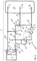
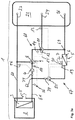
- Fig. 1 a shows a heating system 1 with a heat generator 2, the primary heat exchanger 3 requires a regulated minimum return temperature.
- a flow 60 of the heat generator 2 is connected to the uppermost port 23 of a buffer memory 22. Load-side connections of the buffer memory 22 are not shown here.
- a return flow increase is provided, which is realized by a RLA three-way valve 8.
- the return temperature is measured by an RLA temperature sensor 10 located downstream of the exit of the RLA three-way valve 8.
- the return temperature can also be at another location, eg.
- Example the position shown by the reference numeral 32, are measured.
- the wiring harness is indicated, which extends from the connection point 69 (at the lowest port 26) via the RLA three-way valve 8 to the connection point 62 (in the return 61).
- the temperature detected by the RLA temperature sensor 10 acts either proportionally (for example via a capillary tube sensor and a Dehnscherlement) or three-point integral (for example by means of electric actuator with limit switches) on an actuator 9 for the RLA three-way valve 8.
- a charge pump 4 which is connected in series with a backflow preventer or a gravity brake 34 in order to avoid unwanted return flows or standstill circulation.
- the charge pump 4 is adapted in its flow rate to the power of the heat generator 2 and can also be switched off, in particular when the heat generator 2 is switched off. The adjustment of the flow rate can be done for example by controlling the flow temperature as a reference variable.
- the flow temperature is measured by a VL temperature sensor 56 and acts, for example proportionally to the speed of the charge pump 4.
- the not used for admixture to the return 61 water of the flow 60 passes through the top port 23 for loading in the buffer memory 22.
- a second input of the RLA three-way valve 8 is connected to the output of an AE three-way valve 11, which serves for starting discharge (AE).
- the AE three-way valve 11 leads from the buffer memory 22 initially via a central buffer port 24 to the RLA strand 68 warmer water before the coldest water of a lowermost buffer port 26 of the buffer memory 22 is accessed.
- the access to the warmer water of the middle buffer port 24 causes the water at the entrance of the RLA three-way valve 8 is also warmer and thus less flow water from the flow 60 are mixed got to.
- An actuator 12 of the AE three-way valve 11 can be proportionally controlled by a temperature sensor 13 arranged on the buffer memory 22 in the region of the central buffer connection 24 (for example capillary tube sensor and expansion element) or two-point integral (for example electric actuator with automatic return).
- the heat of condensation of the water vapor contained in the exhaust gas of the heat generator 2 is used.
- An exhaust gas channel 5 of the heat generator 2 for this purpose arranged in an AWT strand 67 exhaust gas heat exchanger 6 in series, which may be formed as a capacitor.
- the exhaust passage 5 is in Fig. 1a
- the exhaust gas heat exchanger 6 is connected on the input side to the lowermost buffer connection 26 and on the output side via a connection point 62 to the return 61.
- the AWT strand is understood to mean the wiring harness running between the connection points 69 and 62 via the exhaust gas heat exchanger 6.
- a differential pressure control valve (DRV) 16 is connected, which is a constant from Flow causes possible independent differential pressure drop, which corresponds to that of the exhaust gas heat exchanger 6 at nominal throughput and is typically between 50 and 100 mbar.
- RLA strand 68 Parallel to the RLA strand 68, which is formed by the series-connected elements DRV 16, RLA three-way valve 8 and AE three-way valve 11 is in the AWT strand 67 of the exhaust gas heat exchanger 6 water side in series with a minimum temperature Switched, which includes a two-way valve 17.
- the control is proportional (for example, capillary tube sensor and expansion element) or three-point integral (for example, electric actuator with limit switches).
- the respectively measured temperature acts as a controlled variable, which is kept constant, wherein the manipulated variable is the water flow rate through the exhaust gas heat exchanger 6.
- the term minimum temperature control does not refer to the minimum return temperature of the heat generator 2 but generally means that through this control the throughput increases with increasing control temperature and is reduced when the control temperature decreases. This also prevents the control temperature drops to unreasonably low temperatures and thus too much water is drawn from the coldest port 26 of the buffer memory 22.
- a minimum circulation of the water must be ensured even at strongly underrun setpoint so that heat from the exhaust gas heat exchanger 6 can get to the WTW temperature sensor 19.
- This minimum circulation can be achieved by means of a bypass 21 (also a two-way valve, but unregulated) connected in parallel with the two-way valve 17 with an adjustable minimum passage. This bypass 21 and thus a minimum circulation are not necessary if the AG temperature sensor 20 supplies the controlled variable.
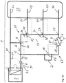
- Fig. 1b shows a variant of the heating system 1 according to the invention, which differs from the variant according to FIG. 1a only differs in that the buffer memory 22 with four Ports 23 to 26 is provided and in addition to the first AE three-way valve 11 is still a second AE three-way valve 27 is provided, which is also used for the Anfahrentlastung.
- the buffer memory 22 with four Ports 23 to 26 is provided and in addition to the first AE three-way valve 11 is still a second AE three-way valve 27 is provided, which is also used for the Anfahrentlastung.
- An actuator 28 of the second AE three-way valve 27 may be controlled proportionally by a second buffer temperature sensor 29 (eg, capillary tube sensor and expansion element) or integral with two points (eg, electric actuator with automatic return).
- the control of the second AE three-way valve 27 may be controlled by a DV temperature sensor 30 which measures the mixing temperature present behind the second AE three-way valve 27.
- the control can here be proportional or three-point integral (for example, electric actuator with limit switches).
- the two AE three-way valves 11 and 27 and the RLA three-way valve 9 by the in Fig. 4b described electrical coupling 31 of the three electrical actuators involved 28, 12 and 9 are controlled solely by the control circuit of the return lift.
- only the minimum return temperature of the return flow increase measured by the RLA temperature sensor 10 is the control or reference variable.
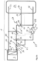
- Fig. 2a shows a heating system 1, extending from the heating system 1 according to Fig. 1a differs in that here the differential pressure control valve (DRV) and the two-way valve (17 in Fig. 1a ) have been omitted.
- the actuator 18 for the MTR three-way valve 33 acts on the ratio of the throughput in the present case at the MTR three-way valve 33 ending RLA strand 68 for throughput through the AWT strand 67, the present case also at the MTR three-way Valve 33 ends.
- the flow through the exhaust gas heat exchanger 6 is increased when a rising temperature is measured by the water side WTW temperature sensor 19 downstream of the exhaust gas heat exchanger 6 and the exhaust gas side AG temperature sensor 20, respectively.
- the control of the actuator 18 via the water-side WTW temperature sensor 19 is controlled, in turn, to ensure a minimum circulation, which is ensured by the bypass 21, which is realized by an adjustable two-way valve.
- the bypass 21 is provided here, the AWT strand 67 branches and ends firstly at the MTR three-way valve 33 and secondly at the connection point 70.
- Fig. 2b shows a heating system 1, which differs from the heating system according to FIG. 2a only differs in that the buffer memory 22 has four ports instead of three.
- the two middle ports 24 and 25 feed two AE three-way valves 11 and 27 for the starting relief.
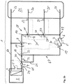
- FIGS. 3a and 3b show heating systems, with respect to the design of the Anfahrentlastung with in the FIGS. 1a or 1b match.
- the differences from FIGS. 1 a and 1 b are given by the strands 67 and 68, which are located downstream of the exhaust gas heat exchanger 6 and the RLA three-way valve 8.
- the charge pump 4 is arranged between the RLA three-way valve 8 and the connection point 62 of return 61 and the exhaust heat exchanger 6 following AWT strand 67.
- a circulating pump 55 is provided in the following on the heat exchanger 6 strand, which serves as a minimum temperature controller, whereby the in the heating system according to Fig.
- the circulating pump 55 is regulated by the temperature, which is determined either on the wastewater side of the WTW temperature sensor 19 or on the exhaust side of the AG temperature sensor 20. If necessary, a minimum circulation in the AWT line 67 can be ensured via the circulation pump 55, for example via a low minimum speed or via a pulsed operation.
- the control can also be proportional or three-point integral. Both the circulation pump 55 and the charge pump 4 are connected in series with a backflow preventer or a gravity brake 34.
- the heating system according to Fig. 3b differs from the system according to Fig. 3a only in that according to Fig. 3b a buffer memory 22 with four terminals 23 to 26th is provided so that there are two AE three-way valves 11 and 27 for the Anfahrentlastung.
- a buffer memory 22 with four terminals 23 to 26th is provided so that there are two AE three-way valves 11 and 27 for the Anfahrentlastung.
- Fig. 1b directed.
- Fig. 4a shows a circuit for implementing the coupling 15, which makes it possible to control the AE three-way valve 11 and the RLA three-way valve 8 with a single control.
- the AE three-way valve 11 can only leave the "fully open” status by closing when the RLA three-way valve 8 is fully closed.
- a three-way valve is considered in the context of the invention then as fully open when the entrance to which the warmer water is present (in the example of Fig. 1a and the RLA three-way valve 8 of the input connected to the flow 60) is fully opened and the other input is fully closed. Accordingly, a three-way valve is then completely closed when the input, at which the warmer medium is present, is completely closed. Then the other input for the colder medium is fully open. In a three-way valve of the type concerned here, both inputs are never closed at the same time.
- the RLA three-way valve 8 Only when the temperature of the water from the central port 24 continues to be insufficient, the RLA three-way valve 8 starts to open, so that too Supply water from the flow 60 the return 61 is mixed. Conversely, when the minimum temperature is exceeded, first only the RLA valve 8 is closed. Only when the RLA three-way valve 8 is fully closed, the AE three-way valve 11 may begin to close. This ensures that as much as possible of the feed water from the feed 60 is fed into the buffer memory 22 in the uppermost port 23 and the temperature stratification within the buffer storage remains as stable as possible.
- Fig. 4a are now shown schematically the servo motor 9 for the RLA three-way valve 8 and the servo motor 12 for the AE three-way valve 11 with an electrical connection.
- the cascade-type interconnection will be explained below with reference to an example. It should first be assumed that both three-way mixing valves are fully closed, the two servomotors 9 and 12 are thus in the "closed” position. Is now given over the scheme of the command "open”, in Fig. 4a symbolized by a switch 63, a circuit is closed to the servo motor 12 and the motor starts to move from the position "to" in the position "open” as long as the command "open” remains.
- a limit switch 64 automatically reverses, so that the circuit is now closed on the servomotor 9, which now also moves from the "closed” position "moved to the” on “position. If the RLA three-way valve 8 is also fully opened, the further limit switch 65 will jump over and the circuit will be interrupted. In this extreme case, the return of the heat generator 2 would be fed by the flow 60 alone. This corresponds eg to the state at the start of the heating system 1.
- the closing runs. Receives the interconnection of the control command "close", the circuit intended to close the closed circuit to the servo motor 9 is closed by means of the switch 63. Only when the servomotor 9 is in the "closed” position and thus the RLA three-way valve 8 is fully closed, the further limit switch 66 jumps, so that the servomotor 9 is cut off from the power supply and instead the circuit for the servomotor 12 for the AE three-way valve 11 is closed and can start closing. The opening and closing movements can be stopped by a stop signal at any time be interrupted (three-step control). If the positioning motor 12 is also fully “closed” in position, the other limit switch 66b can also disconnect the circuit.
- the corresponding limit switch 64 to 66 b in each case returns to the starting position in order to ensure the cascade connection.
- the switches are only symbols if the cascade connection is realized electronically or by means of data processing.
- the cascading described above has the advantage that with the signal of a single reference variable, for.
- the RLA three-way mixer 8 and the AE three-way mixer 11 can be controlled together via a single control with a single three-point signal.
- Fig. 4b shows the coupling 31 by means of a cascade connection of the servomotors 9, 12 and 28 of the two AE three-way valves 27 and 11 and the RLA three-way valve 8, which are jointly controlled such that the AE three-way valve 11 and the RLA Three-way valve 8 can only start to open when the upstream three-way valve in the flow direction is already fully open. When closing it is reversed in a corresponding manner.
- the operation of the cascade connection corresponds to that of Fig. 4a , for which reason reference is made to the description in this regard.
- a heating system 1 according to Fig. 7a corresponds to the heating system according to Fig. 1a with the difference that the AE three-way valve 11 and the RLA three-way valve 8 have been combined into a 4-way valve 35.
- a suitable 4-way valve 35 is in Fig. 5a shown schematically.
- An input 39 is connected to the lowest port 26 of the buffer memory 22, an input 38 to the central port 24 of the buffer memory 22 and an input 37 to the flow 60 of the heat generator 2, while the output 36 of the 4-way valve 35 in the Return line 61 opens.
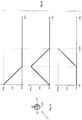
- Fig. 6a three graphs are shown, with which flow passages 41 to 43 of the three inputs 37 to 39 via the position 40 of a not shown here Actuator of the 4-way valve is shown.
- the top graph represents the flow passage 41 of the inlet 37, the middle graph the flow passage 42 of the second inlet 38, and the bottom graph Fig. 6a the flow passage 43 of the input 39 to the output 36 of the 4-way valve 35 as a function of the position of the actuating body, not shown here.
- this 4-way valve 35 for a two-zone buffer replaces the two in the FIGS. 1a . 2a and 3a presented here three-way valves 11 and 8. Again, the control by means of the RLA temperature sensor 10 (alternatively alternatively in the position 32) via a single control signal.
- Fig. 7b shows a heating system 1
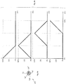
- the to Fig. 7a is similar, with the difference that a 3-zone buffer memory 22 with four terminals 23 to 26 is provided and instead of the 4-way valve, a 5-way valve 44 is used.
- the inputs 46 to 49 are connected so that an input can only be fully opened when all other inputs are completely closed and only the water flows of adjacent inputs can be mixed with each other.
- FIGS. 5a and 6a corresponding manner in the FIGS. 5b and 6b schematically illustrated with the 5-way valve 44, the output 45, the inputs 46 to 49 and the flow passages 51 to 54 of these inputs 46-49 in response to the actuator body position 50th Because of the explanation can on the Description to the FIGS.
- the 5-way valve 44 thus replaces three three-way valves, as z. In Fig. 1b be used.
- the combination of a 3-zone buffer with the 4-way valve 35 and a four-zone buffer with the 5-way valve 44 is also in the heating systems according to the FIGS. 2a . 2 B . 3a and 3b to be used in such a way that the three-way valves in the start-up relief or the return flow increase are replaced.
Landscapes
- Engineering & Computer Science (AREA)
- Physics & Mathematics (AREA)
- Thermal Sciences (AREA)
- Chemical & Material Sciences (AREA)
- Combustion & Propulsion (AREA)
- Mechanical Engineering (AREA)
- General Engineering & Computer Science (AREA)
- Steam Or Hot-Water Central Heating Systems (AREA)
Priority Applications (1)
| Application Number | Priority Date | Filing Date | Title |
|---|---|---|---|
| PL10169694T PL2275748T3 (pl) | 2009-07-15 | 2010-07-15 | Sposób eksploatacji urządzenia grzejnego oraz urządzenie grzejne |
Applications Claiming Priority (1)
| Application Number | Priority Date | Filing Date | Title |
|---|---|---|---|
| DE102009033493 | 2009-07-15 |
Publications (3)
| Publication Number | Publication Date |
|---|---|
| EP2275748A2 EP2275748A2 (de) | 2011-01-19 |
| EP2275748A3 EP2275748A3 (de) | 2016-07-06 |
| EP2275748B1 true EP2275748B1 (de) | 2018-04-04 |
Family
ID=42983635
Family Applications (1)
| Application Number | Title | Priority Date | Filing Date |
|---|---|---|---|
| EP10169694.6A Active EP2275748B1 (de) | 2009-07-15 | 2010-07-15 | Verfahren zum Betrieb einer Heizungsanlage sowie Heizungsanlage |
Country Status (3)
| Country | Link |
|---|---|
| EP (1) | EP2275748B1 (pl) |
| DK (1) | DK2275748T3 (pl) |
| PL (1) | PL2275748T3 (pl) |
Families Citing this family (4)
| Publication number | Priority date | Publication date | Assignee | Title |
|---|---|---|---|---|
| NL2009006C2 (nl) * | 2012-06-14 | 2013-12-17 | Samsom Installaties B V | Inrichting en werkwijze voor het verwarmen van een fluã¯dum, zoals water, verwarming en tapwater. |
| ITTO20130198A1 (it) * | 2013-03-13 | 2014-09-14 | Adsum S R L | Metodo di controllo per un'unita' di riscaldamento con un accumulatore termico per acqua sanitaria |
| DE102016226232A1 (de) * | 2016-12-27 | 2018-06-28 | Robert Bosch Gmbh | Wärmeübergabevorrichtung |
| AT523184B1 (de) | 2020-03-13 | 2021-06-15 | Hargassner Gmbh | Heizungsanlage |
Family Cites Families (4)
| Publication number | Priority date | Publication date | Assignee | Title |
|---|---|---|---|---|
| US4403572A (en) * | 1980-05-16 | 1983-09-13 | Advanced Mechanical Technology, Inc. | Combustion product condensing water heater |
| DE3714261C1 (de) * | 1987-04-29 | 1988-07-07 | Rolf Bommer | Brennwert-Heizkessel und Verfahren zu seinem Betreiben |
| AT400758B (de) * | 1988-06-07 | 1996-03-25 | Vaillant Gmbh | Heizungsanlage |
| DE19628818A1 (de) * | 1996-07-17 | 1998-01-22 | Alois Sauter | Heizungsanlage |
-
2010
- 2010-07-15 DK DK10169694.6T patent/DK2275748T3/da active
- 2010-07-15 PL PL10169694T patent/PL2275748T3/pl unknown
- 2010-07-15 EP EP10169694.6A patent/EP2275748B1/de active Active
Non-Patent Citations (1)
| Title |
|---|
| None * |
Also Published As
| Publication number | Publication date |
|---|---|
| EP2275748A2 (de) | 2011-01-19 |
| PL2275748T3 (pl) | 2018-12-31 |
| DK2275748T3 (da) | 2018-07-23 |
| EP2275748A3 (de) | 2016-07-06 |
Similar Documents
| Publication | Publication Date | Title |
|---|---|---|
| EP2154436B1 (de) | Verfahren und Vorrichtung zur Wärmenutzung | |
| WO1996031694A1 (de) | Verfahren und schaltungsanordnung zum betrieb von wärmespeichern insbesondere für fühlbare wärme | |
| WO2009095010A2 (de) | Heizungsanlage | |
| DE19818030C2 (de) | Verfahren und Vorrichtung zum Betreiben eines Kühlmittelkreises einer Brennkraftmaschine | |
| EP2275748B1 (de) | Verfahren zum Betrieb einer Heizungsanlage sowie Heizungsanlage | |
| EP0675326A1 (de) | Wasserheizanlage zur Bereitung von Brauch- und Heizwasser | |
| EP2426420B1 (de) | Warmwasserbereitungsanlage und Verfahren zum Betreiben einer Warmwasserbereitungsanlage | |
| EP2404114B1 (de) | Heizungsanlage oder kühlungsanlage sowie verfahren zum betrieb von heizungsanlagen oder kühlungsanlagen | |
| EP0892223A2 (de) | Steuer- und Regelgerät für eine Heizungsanlage | |
| EP0098450A2 (de) | Brennstoffbeheizte Wärmequelle | |
| EP0807790A2 (de) | Anordnung und Verfahren zur Bereitstellung von warmem Brauchwasser | |
| EP3800403B1 (de) | Verfahren zum betreiben einer heizvorrichtung, heizvorrichtung | |
| DE102007048728B4 (de) | Heizkessel, Heizungsanlage sowie Verfahren zum Betreiben einer Heizungsanlage, insbesondere zur solaren Heizungsunterstützung | |
| DE10244256B4 (de) | Heizanlage und/oder Kühlanlage mit mindestens einer Wärmequelle | |
| DE19617111A1 (de) | Wasserheizanlage | |
| DE102007063489B4 (de) | Verfahren zum Steuern einer Heizanlage mit einer einen von einem Brenner beheizten Wärmetauscher aufweisenden, insbesondere im Brennwertbereich betriebenen Wärmequelle | |
| EP1792125B1 (de) | Brauchwasserbereiter | |
| DE10259279B3 (de) | Versorgungssystem für Heiz-oder Kühlwasser sowie Verfahren zum Betreiben desselben | |
| WO2009074145A2 (de) | Verfahren zum steuern oder regeln einer heizungsanlage und heizanlage | |
| EP0122475A2 (de) | Heizanlage | |
| AT6001U1 (de) | Heizanlage oder kühlanlage mit mindestens einer wärmequelle | |
| DE102018122503A1 (de) | Saunaofen, Saunakabine mit und Verfahren zum Betrieb eines Saunaofens | |
| EP2339247B1 (de) | Verfahren zur Erwärmung von Brauchwasser | |
| DE19706067A1 (de) | Verfahren zur Steuerung einer Heizungsanlage mit einer Verbrennung fester Biomasse und Vorrichtung zur Durchführung des Verfahrens | |
| CH663268A5 (de) | Heizanlage an einem fernheizsystem. |
Legal Events
| Date | Code | Title | Description |
|---|---|---|---|
| PUAI | Public reference made under article 153(3) epc to a published international application that has entered the european phase |
Free format text: ORIGINAL CODE: 0009012 |
|
| AK | Designated contracting states |
Kind code of ref document: A2 Designated state(s): AL AT BE BG CH CY CZ DE DK EE ES FI FR GB GR HR HU IE IS IT LI LT LU LV MC MK MT NL NO PL PT RO SE SI SK SM TR |
|
| AX | Request for extension of the european patent |
Extension state: BA ME RS |
|
| PUAL | Search report despatched |
Free format text: ORIGINAL CODE: 0009013 |
|
| AK | Designated contracting states |
Kind code of ref document: A3 Designated state(s): AL AT BE BG CH CY CZ DE DK EE ES FI FR GB GR HR HU IE IS IT LI LT LU LV MC MK MT NL NO PL PT RO SE SI SK SM TR |
|
| AX | Request for extension of the european patent |
Extension state: BA ME RS |
|
| RIC1 | Information provided on ipc code assigned before grant |
Ipc: F24D 19/10 20060101AFI20160527BHEP Ipc: F24D 11/00 20060101ALI20160527BHEP |
|
| STAA | Information on the status of an ep patent application or granted ep patent |
Free format text: STATUS: REQUEST FOR EXAMINATION WAS MADE |
|
| 17P | Request for examination filed |
Effective date: 20161230 |
|
| RBV | Designated contracting states (corrected) |
Designated state(s): AL AT BE BG CH CY CZ DE DK EE ES FI FR GB GR HR HU IE IS IT LI LT LU LV MC MK MT NL NO PL PT RO SE SI SK SM TR |
|
| GRAP | Despatch of communication of intention to grant a patent |
Free format text: ORIGINAL CODE: EPIDOSNIGR1 |
|
| STAA | Information on the status of an ep patent application or granted ep patent |
Free format text: STATUS: GRANT OF PATENT IS INTENDED |
|
| INTG | Intention to grant announced |
Effective date: 20171004 |
|
| GRAJ | Information related to disapproval of communication of intention to grant by the applicant or resumption of examination proceedings by the epo deleted |
Free format text: ORIGINAL CODE: EPIDOSDIGR1 |
|
| STAA | Information on the status of an ep patent application or granted ep patent |
Free format text: STATUS: REQUEST FOR EXAMINATION WAS MADE |
|
| INTC | Intention to grant announced (deleted) | ||
| GRAP | Despatch of communication of intention to grant a patent |
Free format text: ORIGINAL CODE: EPIDOSNIGR1 |
|
| STAA | Information on the status of an ep patent application or granted ep patent |
Free format text: STATUS: GRANT OF PATENT IS INTENDED |
|
| GRAS | Grant fee paid |
Free format text: ORIGINAL CODE: EPIDOSNIGR3 |
|
| INTG | Intention to grant announced |
Effective date: 20180130 |
|
| GRAA | (expected) grant |
Free format text: ORIGINAL CODE: 0009210 |
|
| STAA | Information on the status of an ep patent application or granted ep patent |
Free format text: STATUS: THE PATENT HAS BEEN GRANTED |
|
| AK | Designated contracting states |
Kind code of ref document: B1 Designated state(s): AL AT BE BG CH CY CZ DE DK EE ES FI FR GB GR HR HU IE IS IT LI LT LU LV MC MK MT NL NO PL PT RO SE SI SK SM TR |
|
| REG | Reference to a national code |
Ref country code: GB Ref legal event code: FG4D Free format text: NOT ENGLISH |
|
| REG | Reference to a national code |
Ref country code: CH Ref legal event code: EP |
|
| REG | Reference to a national code |
Ref country code: AT Ref legal event code: REF Ref document number: 985997 Country of ref document: AT Kind code of ref document: T Effective date: 20180415 |
|
| REG | Reference to a national code |
Ref country code: DE Ref legal event code: R096 Ref document number: 502010014817 Country of ref document: DE |
|
| REG | Reference to a national code |
Ref country code: IE Ref legal event code: FG4D Free format text: LANGUAGE OF EP DOCUMENT: GERMAN |
|
| REG | Reference to a national code |
Ref country code: DK Ref legal event code: T3 Effective date: 20180716 |
|
| REG | Reference to a national code |
Ref country code: NL Ref legal event code: MP Effective date: 20180404 |
|
| REG | Reference to a national code |
Ref country code: LT Ref legal event code: MG4D |
|
| PG25 | Lapsed in a contracting state [announced via postgrant information from national office to epo] |
Ref country code: NL Free format text: LAPSE BECAUSE OF FAILURE TO SUBMIT A TRANSLATION OF THE DESCRIPTION OR TO PAY THE FEE WITHIN THE PRESCRIBED TIME-LIMIT Effective date: 20180404 |
|
| PG25 | Lapsed in a contracting state [announced via postgrant information from national office to epo] |
Ref country code: NO Free format text: LAPSE BECAUSE OF FAILURE TO SUBMIT A TRANSLATION OF THE DESCRIPTION OR TO PAY THE FEE WITHIN THE PRESCRIBED TIME-LIMIT Effective date: 20180704 Ref country code: AL Free format text: LAPSE BECAUSE OF FAILURE TO SUBMIT A TRANSLATION OF THE DESCRIPTION OR TO PAY THE FEE WITHIN THE PRESCRIBED TIME-LIMIT Effective date: 20180404 Ref country code: BG Free format text: LAPSE BECAUSE OF FAILURE TO SUBMIT A TRANSLATION OF THE DESCRIPTION OR TO PAY THE FEE WITHIN THE PRESCRIBED TIME-LIMIT Effective date: 20180704 Ref country code: FI Free format text: LAPSE BECAUSE OF FAILURE TO SUBMIT A TRANSLATION OF THE DESCRIPTION OR TO PAY THE FEE WITHIN THE PRESCRIBED TIME-LIMIT Effective date: 20180404 Ref country code: SE Free format text: LAPSE BECAUSE OF FAILURE TO SUBMIT A TRANSLATION OF THE DESCRIPTION OR TO PAY THE FEE WITHIN THE PRESCRIBED TIME-LIMIT Effective date: 20180404 Ref country code: ES Free format text: LAPSE BECAUSE OF FAILURE TO SUBMIT A TRANSLATION OF THE DESCRIPTION OR TO PAY THE FEE WITHIN THE PRESCRIBED TIME-LIMIT Effective date: 20180404 Ref country code: LT Free format text: LAPSE BECAUSE OF FAILURE TO SUBMIT A TRANSLATION OF THE DESCRIPTION OR TO PAY THE FEE WITHIN THE PRESCRIBED TIME-LIMIT Effective date: 20180404 |
|
| PG25 | Lapsed in a contracting state [announced via postgrant information from national office to epo] |
Ref country code: HR Free format text: LAPSE BECAUSE OF FAILURE TO SUBMIT A TRANSLATION OF THE DESCRIPTION OR TO PAY THE FEE WITHIN THE PRESCRIBED TIME-LIMIT Effective date: 20180404 Ref country code: GR Free format text: LAPSE BECAUSE OF FAILURE TO SUBMIT A TRANSLATION OF THE DESCRIPTION OR TO PAY THE FEE WITHIN THE PRESCRIBED TIME-LIMIT Effective date: 20180705 Ref country code: LV Free format text: LAPSE BECAUSE OF FAILURE TO SUBMIT A TRANSLATION OF THE DESCRIPTION OR TO PAY THE FEE WITHIN THE PRESCRIBED TIME-LIMIT Effective date: 20180404 |
|
| PG25 | Lapsed in a contracting state [announced via postgrant information from national office to epo] |
Ref country code: PT Free format text: LAPSE BECAUSE OF FAILURE TO SUBMIT A TRANSLATION OF THE DESCRIPTION OR TO PAY THE FEE WITHIN THE PRESCRIBED TIME-LIMIT Effective date: 20180806 |
|
| REG | Reference to a national code |
Ref country code: DE Ref legal event code: R097 Ref document number: 502010014817 Country of ref document: DE |
|
| PG25 | Lapsed in a contracting state [announced via postgrant information from national office to epo] |
Ref country code: EE Free format text: LAPSE BECAUSE OF FAILURE TO SUBMIT A TRANSLATION OF THE DESCRIPTION OR TO PAY THE FEE WITHIN THE PRESCRIBED TIME-LIMIT Effective date: 20180404 Ref country code: CZ Free format text: LAPSE BECAUSE OF FAILURE TO SUBMIT A TRANSLATION OF THE DESCRIPTION OR TO PAY THE FEE WITHIN THE PRESCRIBED TIME-LIMIT Effective date: 20180404 Ref country code: RO Free format text: LAPSE BECAUSE OF FAILURE TO SUBMIT A TRANSLATION OF THE DESCRIPTION OR TO PAY THE FEE WITHIN THE PRESCRIBED TIME-LIMIT Effective date: 20180404 Ref country code: SK Free format text: LAPSE BECAUSE OF FAILURE TO SUBMIT A TRANSLATION OF THE DESCRIPTION OR TO PAY THE FEE WITHIN THE PRESCRIBED TIME-LIMIT Effective date: 20180404 |
|
| PLBE | No opposition filed within time limit |
Free format text: ORIGINAL CODE: 0009261 |
|
| STAA | Information on the status of an ep patent application or granted ep patent |
Free format text: STATUS: NO OPPOSITION FILED WITHIN TIME LIMIT |
|
| PG25 | Lapsed in a contracting state [announced via postgrant information from national office to epo] |
Ref country code: SM Free format text: LAPSE BECAUSE OF FAILURE TO SUBMIT A TRANSLATION OF THE DESCRIPTION OR TO PAY THE FEE WITHIN THE PRESCRIBED TIME-LIMIT Effective date: 20180404 Ref country code: IT Free format text: LAPSE BECAUSE OF FAILURE TO SUBMIT A TRANSLATION OF THE DESCRIPTION OR TO PAY THE FEE WITHIN THE PRESCRIBED TIME-LIMIT Effective date: 20180404 |
|
| REG | Reference to a national code |
Ref country code: CH Ref legal event code: PL |
|
| 26N | No opposition filed |
Effective date: 20190107 |
|
| GBPC | Gb: european patent ceased through non-payment of renewal fee |
Effective date: 20180715 |
|
| PG25 | Lapsed in a contracting state [announced via postgrant information from national office to epo] |
Ref country code: LU Free format text: LAPSE BECAUSE OF NON-PAYMENT OF DUE FEES Effective date: 20180715 Ref country code: MC Free format text: LAPSE BECAUSE OF FAILURE TO SUBMIT A TRANSLATION OF THE DESCRIPTION OR TO PAY THE FEE WITHIN THE PRESCRIBED TIME-LIMIT Effective date: 20180404 |
|
| REG | Reference to a national code |
Ref country code: BE Ref legal event code: MM Effective date: 20180731 |
|
| REG | Reference to a national code |
Ref country code: IE Ref legal event code: MM4A |
|
| PG25 | Lapsed in a contracting state [announced via postgrant information from national office to epo] |
Ref country code: FR Free format text: LAPSE BECAUSE OF NON-PAYMENT OF DUE FEES Effective date: 20180731 Ref country code: CH Free format text: LAPSE BECAUSE OF NON-PAYMENT OF DUE FEES Effective date: 20180731 Ref country code: LI Free format text: LAPSE BECAUSE OF NON-PAYMENT OF DUE FEES Effective date: 20180731 Ref country code: GB Free format text: LAPSE BECAUSE OF NON-PAYMENT OF DUE FEES Effective date: 20180715 Ref country code: IE Free format text: LAPSE BECAUSE OF NON-PAYMENT OF DUE FEES Effective date: 20180715 |
|
| PG25 | Lapsed in a contracting state [announced via postgrant information from national office to epo] |
Ref country code: BE Free format text: LAPSE BECAUSE OF NON-PAYMENT OF DUE FEES Effective date: 20180731 Ref country code: SI Free format text: LAPSE BECAUSE OF FAILURE TO SUBMIT A TRANSLATION OF THE DESCRIPTION OR TO PAY THE FEE WITHIN THE PRESCRIBED TIME-LIMIT Effective date: 20180404 |
|
| REG | Reference to a national code |
Ref country code: AT Ref legal event code: MM01 Ref document number: 985997 Country of ref document: AT Kind code of ref document: T Effective date: 20180715 |
|
| PG25 | Lapsed in a contracting state [announced via postgrant information from national office to epo] |
Ref country code: AT Free format text: LAPSE BECAUSE OF NON-PAYMENT OF DUE FEES Effective date: 20180715 |
|
| PG25 | Lapsed in a contracting state [announced via postgrant information from national office to epo] |
Ref country code: MT Free format text: LAPSE BECAUSE OF FAILURE TO SUBMIT A TRANSLATION OF THE DESCRIPTION OR TO PAY THE FEE WITHIN THE PRESCRIBED TIME-LIMIT Effective date: 20180404 |
|
| PG25 | Lapsed in a contracting state [announced via postgrant information from national office to epo] |
Ref country code: TR Free format text: LAPSE BECAUSE OF FAILURE TO SUBMIT A TRANSLATION OF THE DESCRIPTION OR TO PAY THE FEE WITHIN THE PRESCRIBED TIME-LIMIT Effective date: 20180404 |
|
| PG25 | Lapsed in a contracting state [announced via postgrant information from national office to epo] |
Ref country code: HU Free format text: LAPSE BECAUSE OF FAILURE TO SUBMIT A TRANSLATION OF THE DESCRIPTION OR TO PAY THE FEE WITHIN THE PRESCRIBED TIME-LIMIT; INVALID AB INITIO Effective date: 20100715 |
|
| PG25 | Lapsed in a contracting state [announced via postgrant information from national office to epo] |
Ref country code: MK Free format text: LAPSE BECAUSE OF NON-PAYMENT OF DUE FEES Effective date: 20180404 Ref country code: CY Free format text: LAPSE BECAUSE OF FAILURE TO SUBMIT A TRANSLATION OF THE DESCRIPTION OR TO PAY THE FEE WITHIN THE PRESCRIBED TIME-LIMIT Effective date: 20180404 |
|
| PG25 | Lapsed in a contracting state [announced via postgrant information from national office to epo] |
Ref country code: IS Free format text: LAPSE BECAUSE OF FAILURE TO SUBMIT A TRANSLATION OF THE DESCRIPTION OR TO PAY THE FEE WITHIN THE PRESCRIBED TIME-LIMIT Effective date: 20180804 |
|
| PGFP | Annual fee paid to national office [announced via postgrant information from national office to epo] |
Ref country code: PL Payment date: 20210707 Year of fee payment: 12 Ref country code: DK Payment date: 20210721 Year of fee payment: 12 |
|
| REG | Reference to a national code |
Ref country code: DK Ref legal event code: EBP Effective date: 20220731 |
|
| PG25 | Lapsed in a contracting state [announced via postgrant information from national office to epo] |
Ref country code: DK Free format text: LAPSE BECAUSE OF NON-PAYMENT OF DUE FEES Effective date: 20220731 |
|
| PG25 | Lapsed in a contracting state [announced via postgrant information from national office to epo] |
Ref country code: PL Free format text: LAPSE BECAUSE OF NON-PAYMENT OF DUE FEES Effective date: 20220715 |
|
| PGFP | Annual fee paid to national office [announced via postgrant information from national office to epo] |
Ref country code: DE Payment date: 20250731 Year of fee payment: 16 |