EP2274196B1 - Windshield installation device and method of use - Google Patents
Windshield installation device and method of use Download PDFInfo
- Publication number
- EP2274196B1 EP2274196B1 EP08746643A EP08746643A EP2274196B1 EP 2274196 B1 EP2274196 B1 EP 2274196B1 EP 08746643 A EP08746643 A EP 08746643A EP 08746643 A EP08746643 A EP 08746643A EP 2274196 B1 EP2274196 B1 EP 2274196B1
- Authority
- EP
- European Patent Office
- Prior art keywords
- tubular member
- windshield
- assembly
- suction device
- set forth
- Prior art date
- Legal status (The legal status is an assumption and is not a legal conclusion. Google has not performed a legal analysis and makes no representation as to the accuracy of the status listed.)
- Active
Links
- 238000009434 installation Methods 0.000 title claims description 34
- 238000000034 method Methods 0.000 title claims description 6
- 230000008878 coupling Effects 0.000 claims description 5
- 238000010168 coupling process Methods 0.000 claims description 5
- 238000005859 coupling reaction Methods 0.000 claims description 5
- 230000004323 axial length Effects 0.000 claims 1
- 238000010276 construction Methods 0.000 description 6
- 239000000463 material Substances 0.000 description 3
- 239000011521 glass Substances 0.000 description 2
- 229910001369 Brass Inorganic materials 0.000 description 1
- 229910000831 Steel Inorganic materials 0.000 description 1
- 239000010951 brass Substances 0.000 description 1
- 230000002860 competitive effect Effects 0.000 description 1
- 239000010959 steel Substances 0.000 description 1
Images


Classifications
-
- B—PERFORMING OPERATIONS; TRANSPORTING
- B60—VEHICLES IN GENERAL
- B60J—WINDOWS, WINDSCREENS, NON-FIXED ROOFS, DOORS, OR SIMILAR DEVICES FOR VEHICLES; REMOVABLE EXTERNAL PROTECTIVE COVERINGS SPECIALLY ADAPTED FOR VEHICLES
- B60J1/00—Windows; Windscreens; Accessories therefor
- B60J1/004—Mounting of windows
-
- B—PERFORMING OPERATIONS; TRANSPORTING
- B25—HAND TOOLS; PORTABLE POWER-DRIVEN TOOLS; MANIPULATORS
- B25B—TOOLS OR BENCH DEVICES NOT OTHERWISE PROVIDED FOR, FOR FASTENING, CONNECTING, DISENGAGING OR HOLDING
- B25B11/00—Work holders not covered by any preceding group in the subclass, e.g. magnetic work holders, vacuum work holders
- B25B11/005—Vacuum work holders
- B25B11/007—Vacuum work holders portable, e.g. handheld
-
- B—PERFORMING OPERATIONS; TRANSPORTING
- B60—VEHICLES IN GENERAL
- B60J—WINDOWS, WINDSCREENS, NON-FIXED ROOFS, DOORS, OR SIMILAR DEVICES FOR VEHICLES; REMOVABLE EXTERNAL PROTECTIVE COVERINGS SPECIALLY ADAPTED FOR VEHICLES
- B60J1/00—Windows; Windscreens; Accessories therefor
- B60J1/004—Mounting of windows
- B60J1/005—Mounting of windows using positioning means during mounting
-
- B—PERFORMING OPERATIONS; TRANSPORTING
- B62—LAND VEHICLES FOR TRAVELLING OTHERWISE THAN ON RAILS
- B62D—MOTOR VEHICLES; TRAILERS
- B62D65/00—Designing, manufacturing, e.g. assembling, facilitating disassembly, or structurally modifying motor vehicles or trailers, not otherwise provided for
- B62D65/02—Joining sub-units or components to, or positioning sub-units or components with respect to, body shell or other sub-units or components
- B62D65/06—Joining sub-units or components to, or positioning sub-units or components with respect to, body shell or other sub-units or components the sub-units or components being doors, windows, openable roofs, lids, bonnets, or weather strips or seals therefor
-
- Y—GENERAL TAGGING OF NEW TECHNOLOGICAL DEVELOPMENTS; GENERAL TAGGING OF CROSS-SECTIONAL TECHNOLOGIES SPANNING OVER SEVERAL SECTIONS OF THE IPC; TECHNICAL SUBJECTS COVERED BY FORMER USPC CROSS-REFERENCE ART COLLECTIONS [XRACs] AND DIGESTS
- Y10—TECHNICAL SUBJECTS COVERED BY FORMER USPC
- Y10T—TECHNICAL SUBJECTS COVERED BY FORMER US CLASSIFICATION
- Y10T29/00—Metal working
- Y10T29/49—Method of mechanical manufacture
- Y10T29/49998—Work holding
Definitions
- a windshield installation device which can be operated by a single technician is disclosed in EP 1 785 300 .
- This device includes a first suction assembly for coupling to a vehicle side window and which includes an L-shaped tubular pivot member, a first portion of which connects together two suction cups of the first assembly, and a second portion of which extends substantially perpendicular to the first portion.
- a second suction assembly is provided for coupling to the windshield.
- the second assembly includes support blocks which slidably and rotatably support an elongate rod.
- the elongate rod can be positioned on the second portion of the tubular pivot member of the first assembly to allow the windshield to be positioned adjacent a windshield opening, whilst being pivotably supported by the first assembly coupled to the vehicle side window.
- the present invention provides a windshield installation device comprising a first assembly including a suction device, a first tubular member connected to the suction device, the first tubular member having a first end and a second end, and a second tubular member having a first portion and a second portion extending substantially perpendicular to the first portion, the first portion positioned within the first end of the first tubular member in a first configuration, the first portion positioned within the second end of the first tubular member in a second configuration, wherein the suction device is coupled to a first window of a vehicle in the first configuration, and where the suction device is coupled to a second window of the vehicle in the second configuration; and a second assembly for coupling to a windshield.
- the first portion of the second tubular member has a diameter less than a diameter of the first tubular member, the first portion adapted to slide within the first tubular member.
- the windshield installation device may also include a second assembly which includes a suction device, a bracket connected to the suction device, a third tubular member defining a bore and connected to the bracket, the bracket adapted to pivot with respect to the third tubular member, and an elongated rod positioned and adapted to slide within the bore, wherein the elongated rod is adapted to couple to the second portion of the second tubular member of the first assembly.
- the present invention also provides a windshield installation device comprising a first assembly and a second assembly.
- the first assembly includes a suction device, a first tubular member connected to the suction device, and a second tubular member having a first portion and a second portion extending substantially perpendicular to the first portion, the first portion having a diameter less than a diameter of the first tubular member, the first portion adapted to slide within the first tubular member.
- the second assembly includes a suction device, a bracket connected to the suction device, a third tubular member defining a bore and connected to the bracket, the bracket adapted to pivot with respect to the third tubular member, and an elongated rod positioned and adapted to slide within the bore, wherein the elongated rod is adapted to couple to the second portion of the second tubular member of the first assembly.
- the present invention further provides a method of installing a windshield on a vehicle, the vehicle including a windshield opening and a side window.
- the method comprises the acts of attaching a first assembly to the side window, the first assembly including a suction device, a first tubular member coupled to the suction device, and a substantially L-shaped second tubular member adapted to slide within the first tubular member; attaching a second assembly to the windshield, the second assembly including a second suction device, a third tubular member coupled to the second suction device, and a rod supported by the third tubular member; positioning the rod on the L-shaped second tubular member; positioning the windshield adjacent the windshield opening; and securing the windshield to the windshield opening.
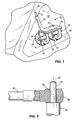
- FIG. 1 is a perspective view of a pivot portion of a windshield installation device which does not form part of the invention.
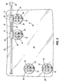
- FIG. 2 is a front view of a support portion of the windshield installation device coupled to a windshield.
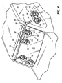
- FIG. 3 is a perspective view of the windshield installation device supporting a windshield for installation in a vehicle.
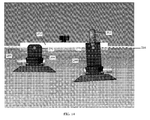
- FIG. 4 is a perspective view of the windshield installation device with the windshield positioned for installation in the vehicle.
- FIG. 5 is a section view taken along line 5-5 of FIG. 4 .
- FIG. 6 is a front view of a first assembly of a windshield installation device embodying the invention.
- FIG. 7 is a perspective view of the first assembly illustrated in FIG. 6 .
- FIG. 8 is a side view of the first assembly illustrated in FIG. 6 .
- FIG. 9 is an exploded view of the first assembly illustrated in FIG. 6 .
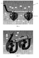
- FIG. 10 is a perspective view of a second assembly of a windshield installation device.
- FIG. 11 is an enlarged perspective view of a portion of the second assembly illustrated in FIG. 10 .
- FIG. 12 is an enlarged perspective view of a portion of the second assembly illustrated in FIG. 10 .
- FIG. 13 is a rear perspective view of a portion of the second assembly illustrated in FIG. 10 .
- FIG. 14 is a top view of a portion of the second assembly illustrated in FIG. 10 .
- FIG. 1-5 illustrate a windshield installation device 10 which does not form part of the present invention.
- the device 10 includes a pivot assembly 12 that attaches to a side window 14 of a vehicle.
- the pivot assembly 12 includes a first suction device 16, a second suction device 18, and a pivot member 24 coupled to the first and second suction devices 16, 18.
- Each suction device 16, 18 includes a resilient cup 28, a handle 32 coupled to the cup 28, and a manually actuated vacuum device 34 that removes air from between the cup 28 and a surface to which the suction device is being attached (e.g. the side window 14).
- the construction of the suction devices 16, 18 and the vacuum device 34 are more fully described in commonly assigned U.S. Patent No. 5,772,823 .
- a plate 36 is coupled to the handles 32 and couples the suction devices 16, 18 to one another.
- the plate 36 can include upturned side edges in some embodiments.
- the pivot member 24 is substantially L-shaped and includes a first portion that is coupled to the plate 36 and a depending portion 40 that extends away from the plate 36 and which defines a reduced-diameter cylindrical portion 44 at one end.
- the reduced-diameter cylindrical portion 44 is operable to retract inside of the depending portion 40.
- FIG. 2 illustrates a support assembly 48 of the windshield installation device coupled to a windshield 52 that is to be installed on the vehicle.
- the support assembly 48 includes a third suction device 56 and a fourth suction device 60, both of which are configured similarly to the first and second suction devices 16, 18.
- a channel or plate 64 couples the third and fourth suction devices 56, 60 to one another, and support blocks 68 are coupled to the plate 64.
- the third and fourth suction devices 56, 60 are configured such that a first plane defined by the plate 64 is at an obtuse angle with respect to a second plane defined generally by the windshield 52.
- the support blocks 68 each define a bore 72, and the bores 72 are substantially axially aligned with one another and define an axis 76.
- a generally cylindrical elongated support rod 80 extends through the bores 72 and is both rotatable about the axis 76 and axially moveable with respect to the support blocks 68.
- the support blocks 68 may include bushings and/or bearings to facilitate smooth sliding and rotation of the support rod 80.
- the support rod 80 includes an end portion 84 having external threads adapted to receive a connector 86.
- the connector 86 includes an opening 88 adapted to receive the cylindrical portion 44 of the pivot member 24 (see FIG. 5 ).
- the support rod 80 and pivot member 24 are therefore pivotable with respect to one another about an axis 90 defined by the cylindrical portion 44.
- additional suction devices 92 can be coupled to the windshield 52 to facilitate handling of the windshield 52 during windshield installation.
- the support assembly 48 and the additional suction devices 92 are coupled to the windshield 52, and the pivot assembly 12 is coupled to the side window 14, all by way of manually operating the vacuum devices 34.
- the pivot assembly 12 is positioned on the side window 14 so that the depending portion 40 extends upwardly and forwardly from the plate 36, adjacent a windshield opening 96.
- the support rod 80 is moved axially within the support blocks 68 so that the end portion 84 extends past a side edge of the windshield 52.
- the windshield 52 is manually lifted using the handles 32 of the third and/or fourth suction devices 56, 60 and/or the additional suction devices 92, and the end portion 84 of the support rod 80 is positioned over the cylindrical portion 44 of the pivot member 24.
- the windshield 52 is thereafter at least partially supported by the pivot member 24 and can be pivoted about the axis 90 of the cylindrical portion 44.
- the windshield 52 With the support rod 80 engaged with the pivot member 24, the windshield 52 is manipulated from the position illustrated in FIG. 3 into an installation position over the windshield opening 96 as illustrated in FIG. 4 .
- Manipulating the windshield 52 in this manner will generally include pivoting the windshield 52 and the support assembly 48 about the pivot member 24, sliding the support rod 80 axially within the support blocks 68, and also rotating the windshield 52 about the axis 76.
- the pivotal engagement between the support rod 80 and the pivot assembly 12, along with the sliding and rotating engagement between the support rod 80 and the support blocks 68 movably supports the windshield 52 in such a way that the windshield 52 can be installed by a single technician.
- the technician can first engage the end portion 84 with the pivot member 24, and can then grasp the additional suction devices 92 while walking around the forward portion of the vehicle, thereby pivoting the support rod 80 about the pivot member 24.
- the windshield 52 can be rotated about the axis 76 and moved axially along the support rod 80 until the windshield 52 is properly positioned above the windshield opening 96.
- FIGS. 6-14 illustrate a windshield installation device 100 according to one construction of the present invention.
- the device 100 includes a first assembly 104 (illustrated in FIGS. 6-9 ) that attaches to a side window (e.g., the passenger side window or driver side window) 14 of a vehicle.
- the first assembly 104 includes a first tubular member 108 connected to a first suction device 110 and a second suction device 114.
- the first tubular member 108 can include two collars 118, 122 coupled to an exterior surface of the tubular member 108 such that the tubular member 108 is connected to the first suction device 110 and second suction device 114 through the first collar 118 and the second collar 122, respectively.
- the first tubular member 108 also includes an aperture 126 adapted to receive a quick release pin 130.
- the first tubular member 108 also includes a first end 134 and a second end 138.
- the first suction member 110 and the second suction device 114 each include a resilient cup 142, a handle 146 coupled to the cup 142, and a manually actuated vacuum device 150 that removes air from between the cup 142 and a surface to which the suction device is being attached (e.g., a side window 14 of the vehicle).
- the construction of the suction devices 110, 114 and the vacuum device 150 are more fully described in commonly assigned U.S. Patent No. 5,772,823 .
- the tubular member 108 is connected to a portion of the handle 146 of both the first suction device 110 and the second suction device 114 with a connector 154.
- the connector 154 illustrated in the figures is a nut and a bolt, however other suitable connectors may be utilized to connect the tubular member 108 to the first suction device 110 and the second suction device 114.
- the tubular member 108 can be connected to the first suction device 110 and the second suction device 114 through additional supporting structure as well. Similarly, additional connection points between the tubular member 108 and the first suction device 110 and the second suction device 114 may be implemented.
- the first assembly 104 also includes a second tubular member 158 generally L-shaped.
- the second tubular member 158 includes a diameter less than a diameter of the first tubular member 108.
- the second tubular member 158 includes a first portion 162 adapted to be received by and slide within the first end 134 or the second end 13 8 of the first tubular member 108 (to accommodate a driver side or passenger side mounting).
- the second tubular member 158 includes a plurality of apertures 166 adapted to align with the aperture 126 in the first tubular member 108 and to receive the quick release pin 130. Although two apertures 166 are illustrated in FIG. 9 , additional apertures 166 can be implemented in the first tubular member 108 and the second tubular member 158.
- the second tubular member 158 is adapted to slide within the first tubular member 108 to adjust a position of the second tubular member 158 with respect to the first tubular member 108.
- the second tubular member 158 includes a second portion 170 extending substantially perpendicular to the first portion 162.
- the second tubular member 158 also includes a reduced-diameter cylindrical member 174 coupled to the second portion 170 at a distal end of the second portion 170.
- the reduced-diameter cylindrical member 174 extends from the distal end of the second portion 170 and is operable to retract inside of the second portion 170 via a peg 178 that slides along a track 182 formed in the second portion 170.
- the windshield installation device 100 also includes a second assembly 200 (illustrated in FIGS. 10-14 ) that attaches to a windshield 52 to be installed in a vehicle.
- the second assembly 200 includes a third suction device 204 and a fourth suction device 208.
- the third suction device 204 and the fourth suction device 208 each include a resilient cup 212 and a manually actuated vacuum device 216 that removes air from between the cup 212 and a surface to which the suction device is being attached (e.g., a windshield).
- the construction of the suction devices 204, 208 and the vacuum device 216 are more fully described in commonly assigned U.S. Patent No. 5,772,823 .
- the second assembly 200 also includes a first bracket 220 connected to the third suction device 204 and a second bracket 224 connected to the fourth suction device 208.
- the first bracket 220 includes a body 232, a first leg 236 extending from the body 232, a first flange 240 extending from an end of the first leg 236, a second leg 244 extending from the body 232, and a second flange 248 extending from an end of the second leg 244.
- the first flange 240 and the second flange 248 are connected to a handle 252.
- the second bracket 224 includes a body 256, a first leg 260 extending from the body 256, and a second leg 264 extending from the body 256.
- the body 232 of the first bracket 220 is connected to the third suction device 204 with a connector 268.
- the body 256 of the second bracket 224 is connected to the fourth suction device 208 with a connector 268.
- the connector 268 can be a bolt, however other suitable connectors may be utilized to connect the brackets 220, 224 to the respective suction devices 204, 208.
- the second assembly 200 also includes a third tubular member 272 connected to the first and second legs 236, 244 of the first bracket 220 and to the first and second legs 260, 264 of the second bracket 224.
- the first bracket 220 and the second bracket 224 are connected to the third tubular member 272 with a connector 276, which allows the first and second brackets 220, 224 and corresponding suction devices to pivot with respect to the third tubular member 272 to accommodate different shapes and/or contours of windshields.
- the third tubular member 272 defines a bore 280 and an axis 284.
- the second assembly 200 also includes an elongated rod 288 adapted to slide along the axis 284 on bearings within the bore 280 of the third tubular member 272.
- the elongated rod 288 also is rotatable about the axis 284.
- the elongated rod 288 includes a connector 292 secured to a first end 296 that has an opening 300 adapted to receive the reduced-diameter cylindrical member 174 of the first assembly 104.
- the elongated rod 288 is adapted to pivot with respect to reduced-diameter cylindrical member 174.
- the elongated rod 288 also includes a flange 304 at a second end 308 that has a diameter greater than a diameter of the bore 280.
- the third tubular member 272 includes a brake mechanism 312 adapted to slow down movement of the elongated rod 288 through the bore 280.
- the brake mechanism 312 includes a knob connected to one end of a screw, which has a second end positioned inside of the third tubular member 272 adapted to contact the elongated rod 288 to provide sufficient friction to reduce movement of the elongated rod 288 with respect to the third tubular member 272.
- the screw can comprise a material softer than the material of the elongated rod 288.
- brass is a suitable material for the screw to provide sufficient friction and slow movement of the elongated rod 288, which can comprise steel.
- a rubber pad can be connected to a second end of the screw. The rubber pad is positioned inside of the third tubular member 272 and is adapted to contact the elongated rod 288 to provide sufficient friction to reduce movement of the elongated rod 288 with respect to the third tubular member 272. Additional suction devices can be coupled to the windshield 52 to facilitate handling of the windshield 52 during windshield installation.
- installation devices 10, 100 are shown and described herein as facilitating installation of a windshield in an automotive vehicle, it should be appreciated that the device 10, 100 can be utilized in a variety of other applications in which it is desired to at least partially support an object in a moveable manner to facilitate installation or general manipulation thereof.
Description
- Installing a windshield on an automotive vehicle requires precise placement of the windshield. Given the weight and considerable size of windshields, and the arrangement of most cars, installing a windshield is often a two-person job that requires individuals on both the driver's and passenger's side of the vehicle. Many businesses that provide auto glass repair and replacement provide on site service, in which a service technician or a team of technicians travel to the customer's vehicle for repair or replacement of the windshield wherever the vehicle happens to be located. Providing on site service in this manner provides a high level of convenience to the customer and can be a distinct competitive advantage for glass replacement businesses.
- A windshield installation device which can be operated by a single technician is disclosed in
EP 1 785 300 . This device includes a first suction assembly for coupling to a vehicle side window and which includes an L-shaped tubular pivot member, a first portion of which connects together two suction cups of the first assembly, and a second portion of which extends substantially perpendicular to the first portion. A second suction assembly is provided for coupling to the windshield. The second assembly includes support blocks which slidably and rotatably support an elongate rod. The elongate rod can be positioned on the second portion of the tubular pivot member of the first assembly to allow the windshield to be positioned adjacent a windshield opening, whilst being pivotably supported by the first assembly coupled to the vehicle side window. - The present invention provides a windshield installation device comprising a first assembly including a suction device, a first tubular member connected to the suction device, the first tubular member having a first end and a second end, and a second tubular member having a first portion and a second portion extending substantially perpendicular to the first portion, the first portion positioned within the first end of the first tubular member in a first configuration, the first portion positioned within the second end of the first tubular member in a second configuration, wherein the suction device is coupled to a first window of a vehicle in the first configuration, and where the suction device is coupled to a second window of the vehicle in the second configuration; and a second assembly for coupling to a windshield.
- In some embodiments the first portion of the second tubular member has a diameter less than a diameter of the first tubular member, the first portion adapted to slide within the first tubular member. The windshield installation device may also include a second assembly which includes a suction device, a bracket connected to the suction device, a third tubular member defining a bore and connected to the bracket, the bracket adapted to pivot with respect to the third tubular member, and an elongated rod positioned and adapted to slide within the bore, wherein the elongated rod is adapted to couple to the second portion of the second tubular member of the first assembly.
- The present invention also provides a windshield installation device comprising a first assembly and a second assembly. The first assembly includes a suction device, a first tubular member connected to the suction device, and a second tubular member having a first portion and a second portion extending substantially perpendicular to the first portion, the first portion having a diameter less than a diameter of the first tubular member, the first portion adapted to slide within the first tubular member. The second assembly includes a suction device, a bracket connected to the suction device, a third tubular member defining a bore and connected to the bracket, the bracket adapted to pivot with respect to the third tubular member, and an elongated rod positioned and adapted to slide within the bore, wherein the elongated rod is adapted to couple to the second portion of the second tubular member of the first assembly.
- The present invention further provides a method of installing a windshield on a vehicle, the vehicle including a windshield opening and a side window. The method comprises the acts of attaching a first assembly to the side window, the first assembly including a suction device, a first tubular member coupled to the suction device, and a substantially L-shaped second tubular member adapted to slide within the first tubular member; attaching a second assembly to the windshield, the second assembly including a second suction device, a third tubular member coupled to the second suction device, and a rod supported by the third tubular member; positioning the rod on the L-shaped second tubular member; positioning the windshield adjacent the windshield opening; and securing the windshield to the windshield opening.
- Other aspects of the invention will become apparent by consideration of the detailed description and accompanying drawings.
-
FIG. 1 is a perspective view of a pivot portion of a windshield installation device which does not form part of the invention. -
FIG. 2 is a front view of a support portion of the windshield installation device coupled to a windshield. -
FIG. 3 is a perspective view of the windshield installation device supporting a windshield for installation in a vehicle. -
FIG. 4 is a perspective view of the windshield installation device with the windshield positioned for installation in the vehicle. -
FIG. 5 is a section view taken along line 5-5 ofFIG. 4 . -
FIG. 6 is a front view of a first assembly of a windshield installation device embodying the invention. -
FIG. 7 is a perspective view of the first assembly illustrated inFIG. 6 . -
FIG. 8 is a side view of the first assembly illustrated inFIG. 6 . -
FIG. 9 is an exploded view of the first assembly illustrated inFIG. 6 . -
FIG. 10 is a perspective view of a second assembly of a windshield installation device. -
FIG. 11 is an enlarged perspective view of a portion of the second assembly illustrated inFIG. 10 . -
FIG. 12 is an enlarged perspective view of a portion of the second assembly illustrated inFIG. 10 . -
FIG. 13 is a rear perspective view of a portion of the second assembly illustrated inFIG. 10 . -
FIG. 14 is a top view of a portion of the second assembly illustrated inFIG. 10 . - Before any embodiments of the invention are explained in detail, it is to be understood that the invention is not limited in its application to the details of construction and the arrangement of components set forth in the following description or illustrated in the drawings. The invention is capable of other embodiments and of being practiced or of being carried out in various ways. Also, it is to be understood that the phraseology and terminology used herein is for the purpose of description and should not be regarded as limiting.
-
Figures 1-5 illustrate awindshield installation device 10 which does not form part of the present invention. With reference toFIG. 1 , thedevice 10 includes apivot assembly 12 that attaches to aside window 14 of a vehicle. Thepivot assembly 12 includes afirst suction device 16, asecond suction device 18, and apivot member 24 coupled to the first andsecond suction devices suction device resilient cup 28, ahandle 32 coupled to thecup 28, and a manually actuatedvacuum device 34 that removes air from between thecup 28 and a surface to which the suction device is being attached (e.g. the side window 14). The construction of thesuction devices vacuum device 34 are more fully described in commonly assignedU.S. Patent No. 5,772,823 . Aplate 36 is coupled to thehandles 32 and couples thesuction devices plate 36 can include upturned side edges in some embodiments. Thepivot member 24 is substantially L-shaped and includes a first portion that is coupled to theplate 36 and a dependingportion 40 that extends away from theplate 36 and which defines a reduced-diametercylindrical portion 44 at one end. The reduced-diametercylindrical portion 44 is operable to retract inside of the dependingportion 40. -
FIG. 2 illustrates asupport assembly 48 of the windshield installation device coupled to awindshield 52 that is to be installed on the vehicle. Thesupport assembly 48 includes athird suction device 56 and afourth suction device 60, both of which are configured similarly to the first andsecond suction devices plate 64 couples the third andfourth suction devices support blocks 68 are coupled to theplate 64. The third andfourth suction devices plate 64 is at an obtuse angle with respect to a second plane defined generally by thewindshield 52. - The
support blocks 68 each define abore 72, and thebores 72 are substantially axially aligned with one another and define anaxis 76. A generally cylindricalelongated support rod 80 extends through thebores 72 and is both rotatable about theaxis 76 and axially moveable with respect to thesupport blocks 68. Thesupport blocks 68 may include bushings and/or bearings to facilitate smooth sliding and rotation of thesupport rod 80. Thesupport rod 80 includes anend portion 84 having external threads adapted to receive a connector 86. The connector 86 includes anopening 88 adapted to receive thecylindrical portion 44 of the pivot member 24 (seeFIG. 5 ). Thesupport rod 80 andpivot member 24 are therefore pivotable with respect to one another about anaxis 90 defined by thecylindrical portion 44. As illustrated,additional suction devices 92 can be coupled to thewindshield 52 to facilitate handling of thewindshield 52 during windshield installation. - Referring also to
FIGS. 3 and4 , thesupport assembly 48 and theadditional suction devices 92 are coupled to thewindshield 52, and thepivot assembly 12 is coupled to theside window 14, all by way of manually operating thevacuum devices 34. Thepivot assembly 12 is positioned on theside window 14 so that the dependingportion 40 extends upwardly and forwardly from theplate 36, adjacent awindshield opening 96. Thesupport rod 80 is moved axially within thesupport blocks 68 so that theend portion 84 extends past a side edge of thewindshield 52. Thewindshield 52 is manually lifted using thehandles 32 of the third and/orfourth suction devices additional suction devices 92, and theend portion 84 of thesupport rod 80 is positioned over thecylindrical portion 44 of thepivot member 24. Thewindshield 52 is thereafter at least partially supported by thepivot member 24 and can be pivoted about theaxis 90 of thecylindrical portion 44. - With the
support rod 80 engaged with thepivot member 24, thewindshield 52 is manipulated from the position illustrated inFIG. 3 into an installation position over thewindshield opening 96 as illustrated inFIG. 4 . Manipulating thewindshield 52 in this manner will generally include pivoting thewindshield 52 and thesupport assembly 48 about thepivot member 24, sliding thesupport rod 80 axially within the support blocks 68, and also rotating thewindshield 52 about theaxis 76. The pivotal engagement between thesupport rod 80 and thepivot assembly 12, along with the sliding and rotating engagement between thesupport rod 80 and the support blocks 68 movably supports thewindshield 52 in such a way that thewindshield 52 can be installed by a single technician. More specifically, the technician can first engage theend portion 84 with thepivot member 24, and can then grasp theadditional suction devices 92 while walking around the forward portion of the vehicle, thereby pivoting thesupport rod 80 about thepivot member 24. From the opposite side of the vehicle as thepivot assembly 12, thewindshield 52 can be rotated about theaxis 76 and moved axially along thesupport rod 80 until thewindshield 52 is properly positioned above thewindshield opening 96. -
Figures 6-14 illustrate a windshield installation device 100 according to one construction of the present invention. The device 100 includes a first assembly 104 (illustrated inFIGS. 6-9 ) that attaches to a side window (e.g., the passenger side window or driver side window) 14 of a vehicle. With reference toFIGS. 6-9 , the first assembly 104 includes a firsttubular member 108 connected to a first suction device 110 and asecond suction device 114. The firsttubular member 108 can include twocollars tubular member 108 such that thetubular member 108 is connected to the first suction device 110 andsecond suction device 114 through thefirst collar 118 and thesecond collar 122, respectively. The firsttubular member 108 also includes an aperture 126 adapted to receive aquick release pin 130. The firsttubular member 108 also includes afirst end 134 and a second end 138. - The first suction member 110 and the
second suction device 114 each include aresilient cup 142, ahandle 146 coupled to thecup 142, and a manually actuatedvacuum device 150 that removes air from between thecup 142 and a surface to which the suction device is being attached (e.g., aside window 14 of the vehicle). The construction of thesuction devices 110, 114 and thevacuum device 150 are more fully described in commonly assignedU.S. Patent No. 5,772,823 . - The
tubular member 108 is connected to a portion of thehandle 146 of both the first suction device 110 and thesecond suction device 114 with aconnector 154. Theconnector 154 illustrated in the figures is a nut and a bolt, however other suitable connectors may be utilized to connect thetubular member 108 to the first suction device 110 and thesecond suction device 114. Thetubular member 108 can be connected to the first suction device 110 and thesecond suction device 114 through additional supporting structure as well. Similarly, additional connection points between thetubular member 108 and the first suction device 110 and thesecond suction device 114 may be implemented. - The first assembly 104 also includes a second
tubular member 158 generally L-shaped. The secondtubular member 158 includes a diameter less than a diameter of the firsttubular member 108. The secondtubular member 158 includes afirst portion 162 adapted to be received by and slide within thefirst end 134 or the second end 13 8 of the first tubular member 108 (to accommodate a driver side or passenger side mounting). The secondtubular member 158 includes a plurality ofapertures 166 adapted to align with the aperture 126 in the firsttubular member 108 and to receive thequick release pin 130. Although twoapertures 166 are illustrated inFIG. 9 ,additional apertures 166 can be implemented in the firsttubular member 108 and the secondtubular member 158. The secondtubular member 158 is adapted to slide within the firsttubular member 108 to adjust a position of the secondtubular member 158 with respect to the firsttubular member 108. - The second
tubular member 158 includes asecond portion 170 extending substantially perpendicular to thefirst portion 162. The secondtubular member 158 also includes a reduced-diametercylindrical member 174 coupled to thesecond portion 170 at a distal end of thesecond portion 170. The reduced-diametercylindrical member 174 extends from the distal end of thesecond portion 170 and is operable to retract inside of thesecond portion 170 via apeg 178 that slides along atrack 182 formed in thesecond portion 170. - The windshield installation device 100 also includes a second assembly 200 (illustrated in
FIGS. 10-14 ) that attaches to awindshield 52 to be installed in a vehicle. With reference toFIGS. 10-14 , thesecond assembly 200 includes athird suction device 204 and afourth suction device 208. Thethird suction device 204 and thefourth suction device 208 each include aresilient cup 212 and a manually actuatedvacuum device 216 that removes air from between thecup 212 and a surface to which the suction device is being attached (e.g., a windshield). The construction of thesuction devices vacuum device 216 are more fully described in commonly assignedU.S. Patent No. 5,772,823 . - The
second assembly 200 also includes afirst bracket 220 connected to thethird suction device 204 and asecond bracket 224 connected to thefourth suction device 208. Thefirst bracket 220 includes abody 232, afirst leg 236 extending from thebody 232, afirst flange 240 extending from an end of thefirst leg 236, asecond leg 244 extending from thebody 232, and asecond flange 248 extending from an end of thesecond leg 244. Thefirst flange 240 and thesecond flange 248 are connected to ahandle 252. Thesecond bracket 224 includes abody 256, afirst leg 260 extending from thebody 256, and asecond leg 264 extending from thebody 256. - The
body 232 of thefirst bracket 220 is connected to thethird suction device 204 with aconnector 268. Similarly, thebody 256 of thesecond bracket 224 is connected to thefourth suction device 208 with aconnector 268. Theconnector 268 can be a bolt, however other suitable connectors may be utilized to connect thebrackets respective suction devices - The
second assembly 200 also includes a thirdtubular member 272 connected to the first andsecond legs first bracket 220 and to the first andsecond legs second bracket 224. Thefirst bracket 220 and thesecond bracket 224 are connected to the thirdtubular member 272 with aconnector 276, which allows the first andsecond brackets tubular member 272 to accommodate different shapes and/or contours of windshields. - The third
tubular member 272 defines a bore 280 and anaxis 284. Thesecond assembly 200 also includes anelongated rod 288 adapted to slide along theaxis 284 on bearings within the bore 280 of the thirdtubular member 272. Theelongated rod 288 also is rotatable about theaxis 284. Theelongated rod 288 includes aconnector 292 secured to afirst end 296 that has anopening 300 adapted to receive the reduced-diametercylindrical member 174 of the first assembly 104. Theelongated rod 288 is adapted to pivot with respect to reduced-diametercylindrical member 174. Theelongated rod 288 also includes aflange 304 at asecond end 308 that has a diameter greater than a diameter of the bore 280. The thirdtubular member 272 includes abrake mechanism 312 adapted to slow down movement of theelongated rod 288 through the bore 280. Thebrake mechanism 312 includes a knob connected to one end of a screw, which has a second end positioned inside of the thirdtubular member 272 adapted to contact theelongated rod 288 to provide sufficient friction to reduce movement of theelongated rod 288 with respect to the thirdtubular member 272. The screw can comprise a material softer than the material of theelongated rod 288. For example, brass is a suitable material for the screw to provide sufficient friction and slow movement of theelongated rod 288, which can comprise steel. In other constructions, a rubber pad can be connected to a second end of the screw. The rubber pad is positioned inside of the thirdtubular member 272 and is adapted to contact theelongated rod 288 to provide sufficient friction to reduce movement of theelongated rod 288 with respect to the thirdtubular member 272. Additional suction devices can be coupled to thewindshield 52 to facilitate handling of thewindshield 52 during windshield installation. - Although the
installation devices 10, 100 are shown and described herein as facilitating installation of a windshield in an automotive vehicle, it should be appreciated that thedevice 10, 100 can be utilized in a variety of other applications in which it is desired to at least partially support an object in a moveable manner to facilitate installation or general manipulation thereof. - Various features of the invention are set forth in the following claims.
Claims (13)
- A windshield installation device comprising:a first assembly (104) including
a suction device (110, 114),
a first tubular member (108) connected to the suction device (110, 114), the first tubular member (108) having a first end (134) and a second end (138), and
a second tubular member (158) having a first portion (162) and a second portion (170) extending substantially perpendicular to the first portion (162), the first portion (162) positioned stedingly within the first end (134) of the first tubular member (108) in a first configuration, the first portion (162) positioned stedingly within the second end (138) of the first tubular member (108) in a second configuration,
wherein the suction device (110, 114) is coupled to a first window of a vehicle in the first configuration, and where the suction device (110, 114) is coupled to a second window of the vehicle in the second configuration; and
a second assembly attached to the distalend of the second portion of the second tubular member for coupling to a windshield. - The windshield installation device as set forth in claim 1, wherein the first assembly (104) further includes a cylindrical member (174) coupled to a distal end of the second portion (170) of the second tubular member (158), and wherein the second assembly (200) is adapted to couple to the cylindrical member (174) and pivot with respect to the cylindrical member (174).
- The windshield installation device as set forth in claim 1 or claim 2 wherein the first assembly (104) further includes a second suction device (110, 114), and wherein the first tubular member (108) is connected to the second suction device (110, 114).
- The windshield installation device as set forth in any preceding claim, wherein the first tubular member (108) includes an aperture (126) and the first portion (162) of the second tubular member (158) includes an aperture (166), and wherein the apertures (126, 166) are aligned and adapted to receive a connector (130).
- The windshield installation device as set forth in claim 4, wherein the first portion (162) of the second tubular member (158) includes a plurality of apertures (166) along its axial length to adjust a length between the second portion (170) of the second tubular member (158) and one of the first end (134) and the second end (138) of the first tubular member (108).
- The windshield installation device as set forth in any preceding claim, wherein the second assembly (200) further includes a suction device (204, 208) for coupling to the windshield.
- The windshield installation device as set forth in any preceding claim, wherein the second assembly (200) further includes a third tubular member (272) defining a bore (280) and is connected to the suction device (204, 208), the second assembly (200) further including an elongated rod (288) adapted to move within the bore (280).
- The windshield installation device as set forth in claim 7, wherein the second assembly (200) further includes a bracket (220) having a body (232), a first leg (236) extending from the body (232), a first flange (240) extending from the first leg (236), a second leg (244) extending from the body (232), and a second flange (248) extending from the second leg (244), and wherein the body (232) is connected to the suction device (204), and wherein the first leg (236) and the second leg (244) is connected to the third tubular member (272), and wherein the first flange (240) and the second flange (248) is connected to a handle (252).
- The windshield installation device as set forth in claim 7 or claim 8, wherein the second assembly (200) further includes a second suction device (208), and wherein the third tubular member (272) is connected to the first suction device (204) and the second suction device (208).
- The windshield installation device as set forth in claim 9, wherein at least one of the first suction device (204) and the second suction device (208) is pivotable with respect to the third tubular member (272).
- The windshield installation device as set forth in any one of claims 7 to 10, wherein the second assembly (200) further includes a brake mechanism (312) adapted to slow movement of the elongated rod (288) within the bore (280) of the third tubular member (272).
- A method of installing a windshield on a vehicle, the vehicle including a windshield opening and a side window (14), the method comprising:attaching a first assembly (104) to the side window (14), the first assembly (104) including a suction device (110, 114), a first tubular member (108) coupled to the suction device (110, 114), and a substantially L-shaped second tubular member (158) adapted to slide within the first tubular member (108);attaching a second assembly (200) to the windshield, (52), the second assembly (200) including a second suction device (204, 208), a third tubular member (272) coupled to the second suction device (204, 208), and a rod (288) supported by the third tubular member (272);positioning the rod (272) on the L-shaped second tubular member (158);positioning the windshield (52) adjacent the windshield opening (96); andsecuring the windshield (52) to the windshield opening (96).
- The method as set forth in claim 12 wherein positioning the windshield (52) adjacent the windshield opening (96) further comprising swinging the windshield (52) over a front portion of the vehicle.
Priority Applications (1)
| Application Number | Priority Date | Filing Date | Title |
|---|---|---|---|
| PL08746643T PL2274196T3 (en) | 2008-04-23 | 2008-04-23 | Windshield installation device and method of use |
Applications Claiming Priority (1)
| Application Number | Priority Date | Filing Date | Title |
|---|---|---|---|
| PCT/US2008/061259 WO2009131576A1 (en) | 2008-04-23 | 2008-04-23 | Windshield installation device and method of use |
Publications (3)
| Publication Number | Publication Date |
|---|---|
| EP2274196A1 EP2274196A1 (en) | 2011-01-19 |
| EP2274196A4 EP2274196A4 (en) | 2011-11-09 |
| EP2274196B1 true EP2274196B1 (en) | 2013-03-06 |
Family
ID=41217094
Family Applications (1)
| Application Number | Title | Priority Date | Filing Date |
|---|---|---|---|
| EP08746643A Active EP2274196B1 (en) | 2008-04-23 | 2008-04-23 | Windshield installation device and method of use |
Country Status (7)
| Country | Link |
|---|---|
| US (1) | US8672309B2 (en) |
| EP (1) | EP2274196B1 (en) |
| JP (1) | JP5591793B2 (en) |
| CN (1) | CN102056790A (en) |
| ES (1) | ES2409933T3 (en) |
| PL (1) | PL2274196T3 (en) |
| WO (1) | WO2009131576A1 (en) |
Families Citing this family (14)
| Publication number | Priority date | Publication date | Assignee | Title |
|---|---|---|---|---|
| GB2470035B (en) * | 2009-05-06 | 2013-12-18 | Belron Hungary Kft Zug Branch | Suction lifting device for glazing panels with cantilever handle |
| FR2952023B1 (en) * | 2009-11-02 | 2011-11-11 | Robotic Consulting | DEVICE FOR ASSISTING THE INSTALLATION OF A WINDSCREEN OR THE LIKE |
| FR2958254B1 (en) * | 2010-04-06 | 2013-05-31 | Peugeot Citroen Automobiles Sa | TOOL FOR SETTING FIXED GLASSES |
| GB201018558D0 (en) * | 2010-11-03 | 2010-12-15 | Belron Hungary Kft Zug Branch | Windscreen installation apparatus and method |
| CN102756348B (en) * | 2012-07-31 | 2014-07-02 | 奇瑞汽车股份有限公司 | Mounting tool for glass locating buckle |
| US9855897B2 (en) * | 2013-03-12 | 2018-01-02 | Ken Kniepmann | Vehicle mountable carrier system |
| CN103264738B (en) * | 2013-06-07 | 2015-07-01 | 上海发那科机器人有限公司 | Automatic assembling system and method for vehicle windshield glass |
| CN103624514B (en) * | 2013-09-29 | 2015-09-02 | 南车青岛四方机车车辆股份有限公司 | A kind of high speed motor car front screen erecting device and installation method |
| US20150360737A1 (en) * | 2014-06-12 | 2015-12-17 | Richard E. Brummett | Vehicle glass removal and replacement system and method |
| US10190345B2 (en) * | 2015-05-21 | 2019-01-29 | Kyle S. McCullough | Suction cup child restraint lock for sliding doors/windows |
| US11529849B2 (en) * | 2016-06-24 | 2022-12-20 | Christian M. Foss | Windshield installation system and triangulation method |
| US10710656B2 (en) * | 2017-05-04 | 2020-07-14 | GM Global Technology Operations LLC | Windshield assembly system |
| KR102015063B1 (en) * | 2017-07-31 | 2019-08-28 | 하현수 | Device for exchange a glass by oneself |
| RU177241U1 (en) * | 2017-11-13 | 2018-02-14 | федеральное государственное бюджетное образовательное учреждение высшего образования "Санкт-Петербургский горный университет" | DEVICE MOUNTING DEVICE |
Family Cites Families (40)
| Publication number | Priority date | Publication date | Assignee | Title |
|---|---|---|---|---|
| US3020017A (en) | 1958-12-30 | 1962-02-06 | William S Watson | Placement devices for use in medical, surgical, orthopedic, and like work |
| US3620524A (en) | 1970-06-26 | 1971-11-16 | Joseph Czompi | Automobile windshield installer |
| US4231501A (en) * | 1978-01-13 | 1980-11-04 | Goode David P | Window mount ski rack |
| FR2510933A1 (en) | 1981-08-06 | 1983-02-11 | Renault | DEVICE AND METHOD FOR AUTOMATICALLY FITTING A GLAZING ELEMENT, PAVILION TRIM, OR THE LIKE |
| US4670974A (en) | 1985-11-06 | 1987-06-09 | Westinghouse Electric Corp. | Windshield insertion system for a vehicle on a moving conveyor apparatus |
| US4852237A (en) | 1985-11-09 | 1989-08-01 | Kuka | Method and apparatus for mounting windshields on vehicles |
| US4828303A (en) * | 1987-12-18 | 1989-05-09 | Soria Rolando C | Automobile body protection apparatus and method |
| US5039050A (en) * | 1989-08-25 | 1991-08-13 | Eidschun Robert W | Equipment mounting apparatus |
| US4998711A (en) * | 1990-02-23 | 1991-03-12 | Borg Donald M | Workpiece holder and method of installing a vehicle windshield therewith |
| US5085415A (en) | 1990-04-17 | 1992-02-04 | Shaver Craig A | Windshield installation tool |
| US5112092A (en) | 1991-03-21 | 1992-05-12 | Pucci Ricco D | Apparatus for elmination of vehicle door dents |
| DE69131427T2 (en) | 1991-05-28 | 1999-11-25 | Toshiba Kawasaki Kk | WORKING DEVICE |
| JPH0665577A (en) | 1992-08-19 | 1994-03-08 | Nippon Steel Corp | Production of formed coke having uniform quality, high strength, and few cracks |
| GB2273517B (en) * | 1992-12-21 | 1996-04-03 | Autoglass Ltd | Apparatus and method for installing windows |
| US5429253A (en) | 1993-01-05 | 1995-07-04 | Mcnett; Donald L. | Vehicle mounted lightweight pivoting hoist |
| US5416965A (en) | 1993-01-29 | 1995-05-23 | Mayhugh; Kent R. | On-site method of installing replacement glass in a vehicle |
| JPH0665577U (en) * | 1993-02-24 | 1994-09-16 | 株式会社エキスパートオブジャパン | Tent pole |
| US5398602A (en) * | 1993-09-13 | 1995-03-21 | Taylor; Kim S. | Registration device for positioning silk screen frame against smooth, flat surface |
| US5479689A (en) | 1994-05-24 | 1996-01-02 | Harmon Glass Company | Windshield expansion tool and method for removing vehicle windshields |
| US5556505A (en) | 1994-07-05 | 1996-09-17 | Ford Motor Company | Windshield assembly system |
| US5622093A (en) | 1995-01-19 | 1997-04-22 | Equalizer Industries, Inc. | Automobile windshield removal apparatus and method |
| US5639134A (en) | 1996-01-16 | 1997-06-17 | Auto Glass Specialists, Inc. | Multiposition windshield lifting attachment |
| US5826342A (en) | 1996-08-05 | 1998-10-27 | Equalizer Industries, Inc. | Vehicle windshield removing tool |
| US6578248B1 (en) * | 1997-11-05 | 2003-06-17 | Laslo L. Boldizar | Vehicle window support tool |
| US5953802A (en) | 1998-02-17 | 1999-09-21 | Radzio; Matthew D. | Windshield removal jack |
| US6101702A (en) * | 1998-02-19 | 2000-08-15 | Claycomb; Kevin | Windshield lift and method of use |
| KR100305348B1 (en) | 1999-06-03 | 2001-09-24 | 이계안 | Device for dismounting wind shield/rear glass of scrapped automobile |
| US6413022B1 (en) * | 2000-09-18 | 2002-07-02 | The Boeing Company | Vacuum clamp device |
| US6584925B2 (en) | 2000-12-21 | 2003-07-01 | Larson/Glastron Boats, Inc. | Device and method for handling a boat windshield |
| US6616800B2 (en) * | 2001-03-05 | 2003-09-09 | Rolf O. Eriksson | Method and device for removing windshields |
| FR2828826B1 (en) * | 2001-08-23 | 2003-10-31 | Jean Luc Domeon | GUIDING DEVICE FOR THE INSTALLATION OF GLUE WINDSHIELDS |
| US7039995B2 (en) * | 2002-07-08 | 2006-05-09 | Thompson Bobby D | Windshield removal and replacement apparatus |
| DE202004013157U1 (en) | 2004-08-24 | 2006-01-05 | PMA/Tools Division Autoglas-Zubehör AG | Suction pad grips especially for fitting glass panels into vehicle has pairs of pads connected by adjustable tilt and length supports |
| US7216411B1 (en) * | 2004-09-23 | 2007-05-15 | Mayhugh Kent R | Method for enabling a single technician to install a windshield into a vehicle |
| US20060156533A1 (en) | 2004-09-23 | 2006-07-20 | Mayhugh Kent R | Single technician large windshield installation tool |
| US7322092B2 (en) | 2005-11-14 | 2008-01-29 | Aegis Tools International, Inc. | Windshield installation device and method of use |
| CA2568746A1 (en) * | 2005-11-29 | 2007-05-29 | Her Majesty The Queen In Right Of Canada As Represented By The Solicitor General Of Canada, Acting Through The Commissioner Of The Royal Canadia | Automotive glass clamping system |
| DE102006019519B3 (en) | 2006-04-27 | 2007-10-25 | Proglass Gmbh | Vehicle window device for fitting a vehicle's window in a motor vehicle's window section has a carrier frame with suckers as well as a mounting frame |
| US7628434B2 (en) * | 2006-07-12 | 2009-12-08 | Honda Motor Co., Ltd. | Vacuum-operated vehicle glass handling system |
| FR2952023B1 (en) * | 2009-11-02 | 2011-11-11 | Robotic Consulting | DEVICE FOR ASSISTING THE INSTALLATION OF A WINDSCREEN OR THE LIKE |
-
2008
- 2008-04-23 PL PL08746643T patent/PL2274196T3/en unknown
- 2008-04-23 JP JP2011506247A patent/JP5591793B2/en active Active
- 2008-04-23 WO PCT/US2008/061259 patent/WO2009131576A1/en active Application Filing
- 2008-04-23 CN CN2008801296477A patent/CN102056790A/en active Pending
- 2008-04-23 EP EP08746643A patent/EP2274196B1/en active Active
- 2008-04-23 ES ES08746643T patent/ES2409933T3/en active Active
- 2008-04-23 US US12/989,358 patent/US8672309B2/en active Active
Also Published As
| Publication number | Publication date |
|---|---|
| PL2274196T3 (en) | 2013-09-30 |
| EP2274196A1 (en) | 2011-01-19 |
| EP2274196A4 (en) | 2011-11-09 |
| CN102056790A (en) | 2011-05-11 |
| ES2409933T8 (en) | 2013-09-05 |
| JP2011521819A (en) | 2011-07-28 |
| US20110089619A1 (en) | 2011-04-21 |
| JP5591793B2 (en) | 2014-09-17 |
| ES2409933T3 (en) | 2013-06-28 |
| US8672309B2 (en) | 2014-03-18 |
| WO2009131576A1 (en) | 2009-10-29 |
Similar Documents
| Publication | Publication Date | Title |
|---|---|---|
| EP2274196B1 (en) | Windshield installation device and method of use | |
| US7610666B2 (en) | Windshield installation device and method of use | |
| US11623326B2 (en) | Windscreen installation apparatus and method | |
| US8230547B2 (en) | Connector arrangement for a wiper device on motor vehicle windscreens | |
| EP1964644B1 (en) | Motor-driven grinder | |
| US5190604A (en) | Windshield installation tool | |
| DE102018127090A1 (en) | Hand-held cleaning device | |
| CN209812109U (en) | Positioning device suitable for rectangular pipe processing | |
| US7568279B2 (en) | System and method of installing an instrument panel | |
| JP4185459B2 (en) | Tire fitting processing equipment | |
| JP4305235B2 (en) | Walking stick type parking brake lever and its assembly method | |
| KR100342615B1 (en) | Apparatus for supplying an instrument panel of an automobile | |
| DE202007016885U1 (en) | Assembly tool for car windscreens | |
| WO2014071192A1 (en) | Windshield repair tool and method of use | |
| JPH0724870U (en) | Hand rail attachment / detachment tool | |
| EP1559644A3 (en) | Lifting handle especially for bicycles | |
| SE535078C2 (en) | Handle device, vehicle cab and vehicle | |
| GB2334243A (en) | Tyre bead breaking device |
Legal Events
| Date | Code | Title | Description |
|---|---|---|---|
| PUAI | Public reference made under article 153(3) epc to a published international application that has entered the european phase |
Free format text: ORIGINAL CODE: 0009012 |
|
| 17P | Request for examination filed |
Effective date: 20101103 |
|
| AK | Designated contracting states |
Kind code of ref document: A1 Designated state(s): AT BE BG CH CY CZ DE DK EE ES FI FR GB GR HR HU IE IS IT LI LT LU LV MC MT NL NO PL PT RO SE SI SK TR |
|
| AX | Request for extension of the european patent |
Extension state: AL BA MK RS |
|
| DAX | Request for extension of the european patent (deleted) | ||
| RIN1 | Information on inventor provided before grant (corrected) |
Inventor name: BIRKHAUSER, ROBERT Inventor name: HOWERY, ROBERT |
|
| A4 | Supplementary search report drawn up and despatched |
Effective date: 20111007 |
|
| RIC1 | Information provided on ipc code assigned before grant |
Ipc: B25B 11/00 20060101ALI20110930BHEP Ipc: B62D 65/06 20060101AFI20110930BHEP Ipc: B60J 1/00 20060101ALI20110930BHEP |
|
| GRAJ | Information related to disapproval of communication of intention to grant by the applicant or resumption of examination proceedings by the epo deleted |
Free format text: ORIGINAL CODE: EPIDOSDIGR1 |
|
| GRAP | Despatch of communication of intention to grant a patent |
Free format text: ORIGINAL CODE: EPIDOSNIGR1 |
|
| GRAC | Information related to communication of intention to grant a patent modified |
Free format text: ORIGINAL CODE: EPIDOSCIGR1 |
|
| RAP1 | Party data changed (applicant data changed or rights of an application transferred) |
Owner name: AEGIS TOOLS INTERNATIONAL, INC. |
|
| RIN1 | Information on inventor provided before grant (corrected) |
Inventor name: BIRKHAUSER, ROBERT Inventor name: HOWERY, ROBERT |
|
| GRAP | Despatch of communication of intention to grant a patent |
Free format text: ORIGINAL CODE: EPIDOSNIGR1 |
|
| GRAS | Grant fee paid |
Free format text: ORIGINAL CODE: EPIDOSNIGR3 |
|
| GRAA | (expected) grant |
Free format text: ORIGINAL CODE: 0009210 |
|
| AK | Designated contracting states |
Kind code of ref document: B1 Designated state(s): AT BE BG CH CY CZ DE DK EE ES FI FR GB GR HR HU IE IS IT LI LT LU LV MC MT NL NO PL PT RO SE SI SK TR |
|
| REG | Reference to a national code |
Ref country code: GB Ref legal event code: FG4D |
|
| REG | Reference to a national code |
Ref country code: CH Ref legal event code: EP Ref country code: AT Ref legal event code: REF Ref document number: 599429 Country of ref document: AT Kind code of ref document: T Effective date: 20130315 |
|
| REG | Reference to a national code |
Ref country code: IE Ref legal event code: FG4D |
|
| REG | Reference to a national code |
Ref country code: DE Ref legal event code: R096 Ref document number: 602008022713 Country of ref document: DE Effective date: 20130502 |
|
| REG | Reference to a national code |
Ref country code: CH Ref legal event code: NV Representative=s name: MARKS AND CLERK (LUXEMBOURG) LLP, CH |
|
| REG | Reference to a national code |
Ref country code: SE Ref legal event code: TRGR |
|
| REG | Reference to a national code |
Ref country code: ES Ref legal event code: FG2A Ref document number: 2409933 Country of ref document: ES Kind code of ref document: T3 Effective date: 20130628 |
|
| REG | Reference to a national code |
Ref country code: NL Ref legal event code: T3 |
|
| PG25 | Lapsed in a contracting state [announced via postgrant information from national office to epo] |
Ref country code: BG Free format text: LAPSE BECAUSE OF FAILURE TO SUBMIT A TRANSLATION OF THE DESCRIPTION OR TO PAY THE FEE WITHIN THE PRESCRIBED TIME-LIMIT Effective date: 20130606 Ref country code: NO Free format text: LAPSE BECAUSE OF FAILURE TO SUBMIT A TRANSLATION OF THE DESCRIPTION OR TO PAY THE FEE WITHIN THE PRESCRIBED TIME-LIMIT Effective date: 20130606 |
|
| PG25 | Lapsed in a contracting state [announced via postgrant information from national office to epo] |
Ref country code: FI Free format text: LAPSE BECAUSE OF FAILURE TO SUBMIT A TRANSLATION OF THE DESCRIPTION OR TO PAY THE FEE WITHIN THE PRESCRIBED TIME-LIMIT Effective date: 20130306 Ref country code: SI Free format text: LAPSE BECAUSE OF FAILURE TO SUBMIT A TRANSLATION OF THE DESCRIPTION OR TO PAY THE FEE WITHIN THE PRESCRIBED TIME-LIMIT Effective date: 20130306 Ref country code: LV Free format text: LAPSE BECAUSE OF FAILURE TO SUBMIT A TRANSLATION OF THE DESCRIPTION OR TO PAY THE FEE WITHIN THE PRESCRIBED TIME-LIMIT Effective date: 20130306 Ref country code: GR Free format text: LAPSE BECAUSE OF FAILURE TO SUBMIT A TRANSLATION OF THE DESCRIPTION OR TO PAY THE FEE WITHIN THE PRESCRIBED TIME-LIMIT Effective date: 20130607 |
|
| PG25 | Lapsed in a contracting state [announced via postgrant information from national office to epo] |
Ref country code: HR Free format text: LAPSE BECAUSE OF FAILURE TO SUBMIT A TRANSLATION OF THE DESCRIPTION OR TO PAY THE FEE WITHIN THE PRESCRIBED TIME-LIMIT Effective date: 20130306 |
|
| REG | Reference to a national code |
Ref country code: PL Ref legal event code: T3 |
|
| PG25 | Lapsed in a contracting state [announced via postgrant information from national office to epo] |
Ref country code: EE Free format text: LAPSE BECAUSE OF FAILURE TO SUBMIT A TRANSLATION OF THE DESCRIPTION OR TO PAY THE FEE WITHIN THE PRESCRIBED TIME-LIMIT Effective date: 20130306 Ref country code: PT Free format text: LAPSE BECAUSE OF FAILURE TO SUBMIT A TRANSLATION OF THE DESCRIPTION OR TO PAY THE FEE WITHIN THE PRESCRIBED TIME-LIMIT Effective date: 20130708 Ref country code: SK Free format text: LAPSE BECAUSE OF FAILURE TO SUBMIT A TRANSLATION OF THE DESCRIPTION OR TO PAY THE FEE WITHIN THE PRESCRIBED TIME-LIMIT Effective date: 20130306 Ref country code: RO Free format text: LAPSE BECAUSE OF FAILURE TO SUBMIT A TRANSLATION OF THE DESCRIPTION OR TO PAY THE FEE WITHIN THE PRESCRIBED TIME-LIMIT Effective date: 20130306 Ref country code: IS Free format text: LAPSE BECAUSE OF FAILURE TO SUBMIT A TRANSLATION OF THE DESCRIPTION OR TO PAY THE FEE WITHIN THE PRESCRIBED TIME-LIMIT Effective date: 20130706 |
|
| PGFP | Annual fee paid to national office [announced via postgrant information from national office to epo] |
Ref country code: SE Payment date: 20130711 Year of fee payment: 6 Ref country code: LT Payment date: 20130716 Year of fee payment: 6 Ref country code: ES Payment date: 20130711 Year of fee payment: 6 Ref country code: CZ Payment date: 20130712 Year of fee payment: 6 Ref country code: IE Payment date: 20130711 Year of fee payment: 6 Ref country code: CH Payment date: 20130712 Year of fee payment: 6 |
|
| PG25 | Lapsed in a contracting state [announced via postgrant information from national office to epo] |
Ref country code: CY Free format text: LAPSE BECAUSE OF FAILURE TO SUBMIT A TRANSLATION OF THE DESCRIPTION OR TO PAY THE FEE WITHIN THE PRESCRIBED TIME-LIMIT Effective date: 20130306 |
|
| PGFP | Annual fee paid to national office [announced via postgrant information from national office to epo] |
Ref country code: TR Payment date: 20130725 Year of fee payment: 6 Ref country code: PL Payment date: 20130819 Year of fee payment: 6 |
|
| PG25 | Lapsed in a contracting state [announced via postgrant information from national office to epo] |
Ref country code: MC Free format text: LAPSE BECAUSE OF FAILURE TO SUBMIT A TRANSLATION OF THE DESCRIPTION OR TO PAY THE FEE WITHIN THE PRESCRIBED TIME-LIMIT Effective date: 20130306 |
|
| PGFP | Annual fee paid to national office [announced via postgrant information from national office to epo] |
Ref country code: IT Payment date: 20130708 Year of fee payment: 6 |
|
| PLBE | No opposition filed within time limit |
Free format text: ORIGINAL CODE: 0009261 |
|
| STAA | Information on the status of an ep patent application or granted ep patent |
Free format text: STATUS: NO OPPOSITION FILED WITHIN TIME LIMIT |
|
| PG25 | Lapsed in a contracting state [announced via postgrant information from national office to epo] |
Ref country code: DK Free format text: LAPSE BECAUSE OF FAILURE TO SUBMIT A TRANSLATION OF THE DESCRIPTION OR TO PAY THE FEE WITHIN THE PRESCRIBED TIME-LIMIT Effective date: 20130306 |
|
| 26N | No opposition filed |
Effective date: 20131209 |
|
| REG | Reference to a national code |
Ref country code: DE Ref legal event code: R097 Ref document number: 602008022713 Country of ref document: DE Effective date: 20131209 |
|
| REG | Reference to a national code |
Ref country code: LT Ref legal event code: MM4D Effective date: 20140423 |
|
| REG | Reference to a national code |
Ref country code: CH Ref legal event code: PL |
|
| REG | Reference to a national code |
Ref country code: SE Ref legal event code: EUG |
|
| REG | Reference to a national code |
Ref country code: AT Ref legal event code: MM01 Ref document number: 599429 Country of ref document: AT Kind code of ref document: T Effective date: 20140423 |
|
| REG | Reference to a national code |
Ref country code: IE Ref legal event code: MM4A |
|
| PG25 | Lapsed in a contracting state [announced via postgrant information from national office to epo] |
Ref country code: SE Free format text: LAPSE BECAUSE OF NON-PAYMENT OF DUE FEES Effective date: 20140424 Ref country code: LT Free format text: LAPSE BECAUSE OF NON-PAYMENT OF DUE FEES Effective date: 20140423 Ref country code: CH Free format text: LAPSE BECAUSE OF NON-PAYMENT OF DUE FEES Effective date: 20140430 Ref country code: LI Free format text: LAPSE BECAUSE OF NON-PAYMENT OF DUE FEES Effective date: 20140430 Ref country code: CZ Free format text: LAPSE BECAUSE OF NON-PAYMENT OF DUE FEES Effective date: 20140423 |
|
| PG25 | Lapsed in a contracting state [announced via postgrant information from national office to epo] |
Ref country code: AT Free format text: LAPSE BECAUSE OF NON-PAYMENT OF DUE FEES Effective date: 20140423 Ref country code: MT Free format text: LAPSE BECAUSE OF FAILURE TO SUBMIT A TRANSLATION OF THE DESCRIPTION OR TO PAY THE FEE WITHIN THE PRESCRIBED TIME-LIMIT Effective date: 20130306 |
|
| PG25 | Lapsed in a contracting state [announced via postgrant information from national office to epo] |
Ref country code: IT Free format text: LAPSE BECAUSE OF NON-PAYMENT OF DUE FEES Effective date: 20140423 |
|
| PG25 | Lapsed in a contracting state [announced via postgrant information from national office to epo] |
Ref country code: IE Free format text: LAPSE BECAUSE OF NON-PAYMENT OF DUE FEES Effective date: 20140423 |
|
| PG25 | Lapsed in a contracting state [announced via postgrant information from national office to epo] |
Ref country code: HU Free format text: LAPSE BECAUSE OF FAILURE TO SUBMIT A TRANSLATION OF THE DESCRIPTION OR TO PAY THE FEE WITHIN THE PRESCRIBED TIME-LIMIT; INVALID AB INITIO Effective date: 20080423 Ref country code: LU Free format text: LAPSE BECAUSE OF NON-PAYMENT OF DUE FEES Effective date: 20130423 |
|
| REG | Reference to a national code |
Ref country code: PL Ref legal event code: LAPE |
|
| PG25 | Lapsed in a contracting state [announced via postgrant information from national office to epo] |
Ref country code: PL Free format text: LAPSE BECAUSE OF NON-PAYMENT OF DUE FEES Effective date: 20140423 |
|
| REG | Reference to a national code |
Ref country code: ES Ref legal event code: FD2A Effective date: 20151030 |
|
| PG25 | Lapsed in a contracting state [announced via postgrant information from national office to epo] |
Ref country code: ES Free format text: LAPSE BECAUSE OF NON-PAYMENT OF DUE FEES Effective date: 20140424 |
|
| REG | Reference to a national code |
Ref country code: FR Ref legal event code: PLFP Year of fee payment: 9 |
|
| REG | Reference to a national code |
Ref country code: FR Ref legal event code: PLFP Year of fee payment: 10 |
|
| PG25 | Lapsed in a contracting state [announced via postgrant information from national office to epo] |
Ref country code: TR Free format text: LAPSE BECAUSE OF NON-PAYMENT OF DUE FEES Effective date: 20140423 |
|
| REG | Reference to a national code |
Ref country code: FR Ref legal event code: PLFP Year of fee payment: 11 |
|
| REG | Reference to a national code |
Ref country code: FR Ref legal event code: PLFP Year of fee payment: 15 |
|
| PGFP | Annual fee paid to national office [announced via postgrant information from national office to epo] |
Ref country code: BE Payment date: 20220502 Year of fee payment: 15 |
|
| REG | Reference to a national code |
Ref country code: DE Ref legal event code: R082 Ref document number: 602008022713 Country of ref document: DE Representative=s name: COHAUSZ & FLORACK PATENT- UND RECHTSANWAELTE P, DE |
|
| PGFP | Annual fee paid to national office [announced via postgrant information from national office to epo] |
Ref country code: NL Payment date: 20230418 Year of fee payment: 16 |
|
| PGFP | Annual fee paid to national office [announced via postgrant information from national office to epo] |
Ref country code: FR Payment date: 20230419 Year of fee payment: 16 Ref country code: DE Payment date: 20230418 Year of fee payment: 16 |
|
| PGFP | Annual fee paid to national office [announced via postgrant information from national office to epo] |
Ref country code: GB Payment date: 20230530 Year of fee payment: 16 |
|
| REG | Reference to a national code |
Ref country code: BE Ref legal event code: MM Effective date: 20230430 |
|
| PG25 | Lapsed in a contracting state [announced via postgrant information from national office to epo] |
Ref country code: BE Free format text: LAPSE BECAUSE OF NON-PAYMENT OF DUE FEES Effective date: 20230430 |