EP2273667A2 - Motor control unit and vehicle steering apparatus - Google Patents
Motor control unit and vehicle steering apparatus Download PDFInfo
- Publication number
- EP2273667A2 EP2273667A2 EP10168439A EP10168439A EP2273667A2 EP 2273667 A2 EP2273667 A2 EP 2273667A2 EP 10168439 A EP10168439 A EP 10168439A EP 10168439 A EP10168439 A EP 10168439A EP 2273667 A2 EP2273667 A2 EP 2273667A2
- Authority
- EP
- European Patent Office
- Prior art keywords
- angle
- addition angle
- value
- torque
- unit
- Prior art date
- Legal status (The legal status is an assumption and is not a legal conclusion. Google has not performed a legal analysis and makes no representation as to the accuracy of the status listed.)
- Granted
Links
Images


Classifications
-
- H—ELECTRICITY
- H02—GENERATION; CONVERSION OR DISTRIBUTION OF ELECTRIC POWER
- H02P—CONTROL OR REGULATION OF ELECTRIC MOTORS, ELECTRIC GENERATORS OR DYNAMO-ELECTRIC CONVERTERS; CONTROLLING TRANSFORMERS, REACTORS OR CHOKE COILS
- H02P21/00—Arrangements or methods for the control of electric machines by vector control, e.g. by control of field orientation
- H02P21/0003—Control strategies in general, e.g. linear type, e.g. P, PI, PID, using robust control
-
- B—PERFORMING OPERATIONS; TRANSPORTING
- B62—LAND VEHICLES FOR TRAVELLING OTHERWISE THAN ON RAILS
- B62D—MOTOR VEHICLES; TRAILERS
- B62D5/00—Power-assisted or power-driven steering
- B62D5/04—Power-assisted or power-driven steering electrical, e.g. using an electric servo-motor connected to, or forming part of, the steering gear
- B62D5/0457—Power-assisted or power-driven steering electrical, e.g. using an electric servo-motor connected to, or forming part of, the steering gear characterised by control features of the drive means as such
- B62D5/046—Controlling the motor
-
- H—ELECTRICITY
- H02—GENERATION; CONVERSION OR DISTRIBUTION OF ELECTRIC POWER
- H02P—CONTROL OR REGULATION OF ELECTRIC MOTORS, ELECTRIC GENERATORS OR DYNAMO-ELECTRIC CONVERTERS; CONTROLLING TRANSFORMERS, REACTORS OR CHOKE COILS
- H02P21/00—Arrangements or methods for the control of electric machines by vector control, e.g. by control of field orientation
- H02P21/04—Arrangements or methods for the control of electric machines by vector control, e.g. by control of field orientation specially adapted for very low speeds
Landscapes
- Engineering & Computer Science (AREA)
- Power Engineering (AREA)
- Chemical & Material Sciences (AREA)
- Combustion & Propulsion (AREA)
- Transportation (AREA)
- Mechanical Engineering (AREA)
- Steering Control In Accordance With Driving Conditions (AREA)
- Control Of Motors That Do Not Use Commutators (AREA)
- Control Of Ac Motors In General (AREA)
Abstract
Description
- The disclosures of Japanese Patent Application No.
2009-159897 filed on July 6, 2009 - The invention relates to a motor control unit used to drive a brushless motor and a vehicle steering apparatus using the same.
- A brushless motor may be used as a drive source for, for example, a vehicle steering apparatus. An example of a vehicle steering apparatus is an electric power steering apparatus. A motor control unit that controls driving of a brushless motor is usually configured to control the electric current that is supplied to a motor based on the output from a rotational angle sensor that detects the rotational angle of a rotor. As a rotational angle sensor, a resolver that outputs a sine-wave signal and a cosine-wave signal that correspond to the rotational angle (electrical angle) of a rotor is usually used-However, a resolver is expensive, and needs a large number of wires and a large installation space. Therefore, using a resolver as a rotational angle sensor hinders reduction in cost and size of a unit that includes a brushless motor.
-
US Patent Application Publication No. 2007/0229021 A1 describes a sensorless drive method for driving a brushless motor without using a rotational angle sensor. According to the sensorless drive method, the induced voltage that varies depending on the rotational speed of a rotor is estimated in order to estimate the phase of a magnetic pole (electrical angle of the rotor). When the rotor is at a standstill or rotating at a considerably low speed, it is not possible to estimate induced voltage. Therefore, the phase of the magnetic pole is estimated by another method. More specifically, a sensing signal is input in a stator, and a response of the motor to the sensing signal is detected. Then, the rotational position of the rotor is estimated based on the response of the motor. - It is an object of the invention to provide a motor control unit that controls a motor according to a new control method that does not require a rotational angle sensor, and a vehicle steering apparatus that uses such motor control unit.
- An aspect of the invention relates to a motor control unit that controls a motor including a rotor and a stator facing the rotor. A current drive unit drives the motor at an axis current value of a rotating coordinate system that rotates in accordance with a control angle that is a rotational angle used in a control. An addition angle calculation unit calculates an addition angle to be added to the control angle. A control angle calculation unit obtains, at every predetermined calculation cycle, a present value of the control angle by adding the addition angle that is calculated by the addition angle calculation unit to an immediately preceding value of the control angle. An angular speed calculation unit calculates an angular speed of the rotor. An addition angle correction unit corrects the addition angle based on the angular speed calculated by the angular speed calculation unit. A filtering unit filters the angular speed calculated by the angular speed calculation unit.
- The foregoing and further features and advantages of the invention will become apparent from the following description of example embodiments with reference to the accompanying drawings, wherein like numerals are used to represent like elements and wherein:
-
FIG. 1 is a block diagram illustrating the electrical configuration of an electric power steering apparatus that includes a motor control unit according to a first embodiment of the invention; -
FIG. 2 is a view illustrating the configuration of a motor; -
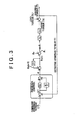
FIG. 3 is a control block diagram of the electric power steering apparatus; -
FIG. 4 is a graph showing an example of the characteristic of the command steering torque with respect to the steering angle; -
FIG 5 is a graph for describing the function of a steering torque limiter; -
FIG 6 is a graph showing an example of a manner of setting the γ-axis command current value; -
FIG 7 is a flowchart for describing the function of an addition angle limiter; -
FIG 8A is a flowchart for describing the function of an addition angle guard when the load angle and the motor torque are positively correlated with each other; -
FIG 8B is a flowchart for describing the function of the addition angle guard when the load angle and the motor torque are negatively correlated with each other; -
FIG 9 is a block diagram illustrating the configurations of an induced voltage estimation unit and a rotational angle estimation unit; -
FIG 10 is a flowchart for describing an example of a process performed in a rotor angular displacement calculation unit; and -
FIG 11 is a flowchart for describing a process performed in the rotor displacement calculation unit according to a second embodiment of the invention. - Hereafter, example embodiments of the invention will be described with reference to the accompanying drawings.
FIG 1 is a block diagram illustrating the electrical configuration of an electric power steering apparatus (an example of a vehicle steering apparatus) that includes a motor control unit according to a first embodiment of the invention. The electric power steering apparatus includes atorque sensor 1 that detects the steering torque T that is applied to asteering wheel 10 that serves as an operation member used to steer a vehicle, an electric motor 3 (brushless motor) that applies a steering assist force to asteering mechanism 2 of the vehicle via a speed reduction mechanism 7, asteering angle sensor 4 that detects the steering angle that is the rotational angle of thesteering wheel 10, a motor control unit 5 that controls driving of themotor 3, and avehicle speed sensor 6 that detects the speed of the vehicle in which the electric power steering apparatus is mounted. Thesteering mechanism 2 is a drive target that is driven by themotor 3. - The motor control unit 5 controls driving of the
motor 3 based on the steering torque detected by thetorque sensor 1, the steering angle detected by thesteering angle sensor 4, and the vehicle speed detected by thevehicle speed sensor 6, thereby providing appropriate steering assistance based on the steering state and the vehicle speed.
In the first embodiment, themotor 3 is a three-phase brushless motor. As illustrated inFIG 2 , themotor 3 includes arotor 50 that serves as a field magnet, and aU-phase stator coil 51, a V-phase stator coil 52, and a W-phase stator coil 53 that are arranged on astator 55 that faces therotor 50. Themotor 3 may be an inner rotor motor in which a stator is arranged on the outer side of a rotor so as to face the rotor, or an outer rotor motor in which a stator is arranged on the inner side of a tubular rotor so as to face the rotor. - A three-phase fixed coordinate system (UVW coordinate system), where the direction in which the
U-phase stator coil 51 extends, the direction in which the V-phase coil 52 extends, and the direction in which the W-phase coil 53 extends are used as the U-axis, the V-axis and W-axis, respectively, is defined. In addition, a two-phase rotating coordinate system (dq coordinate system: actual rotating coordinate system), where the direction of the magnetic poles of therotor 50 is used as the d-axis (axis of the magnetic poles) and the direction that is perpendicular to the d-axis within the rotary plane of therotor 50 is used as the q-axis (torque axis), is defined. The dq coordinate system is a rotating coordinate system that rotates together with therotor 50. In the dq coordinate system, only the q-axis current contributes to generation of torque by therotor 50. Therefore, the d-axis current may be set to 0 and the q-axis current may be controlled based on a desired torque. The rotational angle (rotor angle) θM of therotor 50 is a rotational angle of the d-axis with respect to the U-axis. The dq coordinate system is an actual rotating coordinate system that rotates in accordance with the rotor angle θM. With the use of the rotor angle θM, coordinate conversion may be made between the UVW coordinate system and the dq coordinate system. - In the first embodiment, the control angle θC that indicates the rotational angle used in the control is employed. The control angle θC is an imaginary rotational angle with respect to the U-axis. An imaginary two-phase rotating coordinate system (γδ coordinate system: hereafter, referred to as "imaginary rotating coordinate system". Hereafter, the coordinate axis of the imaginary rotating coordinate system will be referred to as "imaginary axis". Also, the axis current value of the imaginary axis will be referred to as "imaginary axis current value".), where the imaginary axis that forms the control angle θC with the U-axis is used as the γ-axis, and the axis that is advanced 90 degrees from the γ-axis is used as the δ-axis, is defined. When the control angle θC is equal to the rotor angle θM, the γδ coordinate system, which is the imaginary rotating coordinate system, and the dq coordinate system, which is the actual rotating coordinate system, coincide with each other. That is, the γ-axis, which is the imaginary axis, coincides with the d-axis, which is the actual axis, and the δ-axis, which is the imaginary axis, coincides with the q-axis, which is the actual axis. The γδ coordinate system is an imaginary rotating coordinate system that rotates in accordance with the control angle θC. Coordinate conversion may be made between the UVW coordinate system and the γδ coordinate system with the use of the control angle θC.
- The load angle θL (= θC - θM) is defined based on the difference between the control angle θC and the rotor angle θM.
- When the γ-axis current Iγ is supplied to the
motor 3 based on the control angle θC, the q-axis component of the γ-axis current Iγ (orthogonal projection to the q-axis) is used as the q-axis current Iq that contributes to generation of torque by therotor 50. That is, the relationship expressed byEquation 1 is established between the γ-axis current Iγ and the q-axis current Iq.
- Referring again to
FIG. 1 , the motor control unit 5 includes amicrocomputer 11, a drive circuit (inverter circuit) 12 that is controlled by themicrocomputer 11 and that supplies electric power to themotor 3, and acurrent detection unit 13 that detects an electric current that flows through the stator coil of each phase of themotor 3. - The
current detection unit 13 detects the U-phase current IU, the V-phase current IV and the W-phase current IW that flow through theU-phase stator coil 51, the V-phase stator coil 52, and the W-phase stator coil 53 of themotor 3, respectively, (these phase currents will be collectively referred to as "three-phase detected current IUVW" where appropriate). The U-phase current IU, the V-phase current IV and the W-phase current IW are the current values in the directions of the axes of the UVW coordinate system.
Themicrocomputer 11 includes a CPU and memories (a ROM, a RAM, etc.), and serves as multiple function processing units by executing predetermined programs. The multiple function processing units include asteering torque limiter 20, a command steeringtorque setting unit 21, a torquedeviation calculation unit 22, a PI (proportional integral)control unit 23, anaddition angle limiter 24, an additionangle monitoring unit 25, a controlangle calculation unit 26, again change unit 27, an inducedvoltage estimation unit 28, a rotationalangle estimation unit 29, a rotor angulardisplacement calculation unit 30, a command currentvalue preparation unit 31, a currentdeviation calculation unit 32, aPI control unit 33, a γδ /αβ conversion unit 34A, an αβ /UVW conversion unit 34B, a PWM (Pulse Width Modulation)control unit 35, a UVW /αβ conversion unit 36A, an αβ /γδ conversion unit 36B, a torquedeviation monitoring unit 40, and anaddition angle guard 41. - The command steering
torque setting unit 21 sets the command steering torque T* based on the steering angle detected by thesteering angle sensor 4 and the vehicle speed detected by thevehicle speed sensor 6. For example, as shown inFIG. 4 , the command steering torque T* when the steering angle is a positive value (when thesteering wheel 10 is operated clockwise) is set to a positive value (torque applied in the clockwise direction), and the command steering torque T* when the steering angle is a negative value (when thesteering wheel 10 is operated counterclockwise) is set to a negative value (torque applied in the counterclockwise direction). The command steering torque T* is set in such a manner that the absolute value of the command steering torque T* increases (non-linearly increases, in the example inFIG. 4 ) as the absolute value of the steering angle increases. However, the command steering torque T* is set to a value within a range between a predetermined upper limit (positive value (e.g. + 6Nm)) and a predetermined lower limit (negative value (e.g. - 6Nm)). In addition, the command steering torque T* is set in such a manner that the absolute value of the command steering torque T* decreases as the vehicle speed increases. That is, a vehicle speed-sensitive control is execute. - The
steering torque limiter 20 limits the output from thetorque sensor 1 within a range between a predetermined upper saturation value +Tmax (+Tmax > 0 (e.g. +Tmax = 7 Nm)) and a predetermined lower saturation value -Tmax (-Tmax < 0 (e.g. -Tmax = -7 Nm)). More specifically, as shown inFIG. 5 , when the output from thetorque sensor 1 is within the range between the upper saturation value +Tmax and the lower saturation value -Tmax, thesteering torque limiter 20 outputs the detected steering torque T that is the value output from thetorque sensor 1 without limitation. When the detected steering torque T from thetorque sensor 1 is equal to or higher than the upper saturation value +Tmax, thesteering torque limiter 20 outputs the upper saturation value +Tmax. When the detected steering torque T from thetorque sensor 1 is equal to or lower than the lower saturation value -Tmax, thesteering torque limiter 20 outputs the lower saturation value -Tmax. The saturation values +Tmax and -Tmax define a stable range (reliable range) of the output signal from thetorque sensor 1. That is, in the range where the output from thetorque sensor 1 is higher than the upper saturation value +Tmax and the range where the output from thetorque sensor 1 is lower than the lower saturation value -Tmax, the output signal from thetorque sensor 1 is unstable and does not correspond to the actual steering torque. In other words, the saturation values +Tmax and -Tmax are determined based on the output characteristic of thetorque sensor 1. - The torque
deviation calculation unit 22 obtains the deviation (torque deviation) ΔT (= T* - T) of the steering torque T that is detected by thetorque sensor 1 and then subjected to the limiting process executed by the torque limiter 20 (hereinafter, referred to as "detected steering torque T" so as to be distinguished from the command steering torque T*) from the command steering torque T* that is set by the command steeringtorque setting unit 21. ThePI control unit 23 executes the PI calculation on the torque deviation ΔT. That is, the torquedeviation calculation unit 22 and thePI control unit 23 constitute a torque feedback control unit that brings the detected steering torque T to the command steering torque T*. ThePI control unit 23 calculates the addition angle α for the control angle θC by executing the PI calculation on the torque deviation ΔT. Therefore, the torque feedback control unit constitutes an addition angle calculation unit that calculates the addition angle α. - More specifically, the
PI control unit 23 includes aproportional element 23a, anintegral element 23b, and anadder 23c. Note that KP is a proportional gain, KI is an integral gain, and 1/s is an integration operator. A proportional term (proportional calculation value) for a proportional integration calculation is obtained by theproportional element 23a, and an integral term (integral calculation value) for the proportional integration calculation is obtained by theintegral element 23b. Theadder 23c adds up the results of calculations executed by theseelements - The
addition angle limiter 24 is an addition angle limiting unit that imposes limits on the addition angle α obtained by thePI control unit 23. More specifically, theaddition angle limiter 24 limits the addition angle α to a value within a range between a predetermined upper limit UL (positive value) and a predetermined lower limit LL (negative value). The upper limit UL and the lower limit LL are determined based on a predetermined limit mmax (ωmax > 0: e.g. ωmax = 45 degrees). The predetermined limit ωmax is determined based on, for example, the maximum steering angular speed. The maximum steering angular speed is the maximum assumable value of the steering angular speed of thesteering wheel 10, and, for example, approximately 800 deg / sec. - The rate of change in the electrical angle of the rotor 50 (angular speed in the electrical angle: maximum rotor angular speed) at the maximum steering angular speed is expressed by the product of the maximum steering angular speed, the speed reduction ratio of the speed reduction mechanism 7, and the number of pole pairs of the
rotor 50, as indicated byEquation 2. The number of pole pairs is the number of magnetic pole pairs (pair of north pole and south pole) of therotor 50.
- The maximum value of the amount of change in the electrical angle of the
rotor 50 between the calculations (in the calculation cycle) of the control angle θC is expressed by the value obtained by multiplying the maximum rotor angular speed by the calculation cycle, as indicated byEquation 3.
- This maximum value of the amount of change in the rotor angle is the maximum amount of change in the control angle θC that is permitted within one calculation cycle. Therefore, the maximum value of the amount of change in the rotor angle may be used as the limit ωmax. With the use of the limit ωmax, the upper limit UL and the lower limit LL for the addition angle α are expressed by
Equation 4 and Equation 5, respectively.

- The addition angle α obtained after the above-described limiting process executed by the
addition angle limiter 24 is added to the immediately preceding value θC(n-1) (n is the number of the present calculation cycle) of the control angle θC by an addition unit 26A of the control angle calculation unit 26 ("Z - 1" in the drawings indicates the immediately preceding value indicated by a signal). Note that, the mitral value of the control angle θC is a predetermined value (e.g. 0).
The controlangle calculation unit 26 includes the addition unit 26A that adds the addition angle α provided from theaddition angle limiter 24 to the immediately preceding value θC(n-1) of the control angle θC. That is, the controlangle calculation unit 26 calculates the control angle θC at each predetermined calculation cycle. The controlangle calculation unit 26 uses the control angle θC in the immediately preceding calculation cycle as the immediately preceding value θC(n-1), and obtains the present value θC(n) that is the control angle θC in the present calculation cycle based on the immediately preceding value θC(n-1). - The addition
angle monitoring unit 25 monitors the addition angle α that is prepared by theaddition angle limiter 24. More specifically, the additionangle monitoring unit 25 monitors whether the absolute value of the addition angle α has reached the addition angle threshold that is smaller than the limit ωmax. If the addition angle absolute value |α| is equal to or larger than the addition angle threshold, the additionangle monitoring unit 25 provides thegain change unit 27 with the information that the addition angle absolute value |α| is equal to or larger than the addition angle threshold. - When the information that the addition angle absolute value |α| is excessively large (equal to or larger than the addition angle threshold) is provided from the addition
angle monitoring unit 25 to thegain change unit 27, thegain change unit 27 changes the gains (the proportional gain and the integral gain) of thePI control unit 23 to values that are smaller than the normal values. Thus, for example, when the steering speed is high, the gains of thePI control unit 23 are decreased before theaddition angle limiter 24 is actuated. Therefore, limits are less likely to be imposed by theaddition angle limiter 24. As a result, it is possible to stabilize the control, thereby improving a steering feel.
The gains of thePI control unit 23 are changed in such a manner that when the addition angle absolute value |α| is equal to or larger than the addition angle threshold, the gains are decreased. Alternatively, the gains of thePI control unit 23 may be changed in such a manner that the gains are decreased as the addition angle absolute value |α| increases. - The induced
voltage estimation unit 28 estimates the induced voltage that is generated by the rotation of themotor 3. The rotationalangle estimation unit 29 calculates the estimated value θE of the rotational angle (estimated rotational angle) of therotor 50 based on the induced voltage that is estimated by the inducedvoltage estimation unit 28. Concrete examples of the inducedvoltage estimation unit 28 and the rotationalangle estimation unit 29 will be described later. - The rotor angular
displacement calculation unit 30 obtains the amount of change in the estimated rotational angle θE in the calculation cycle to obtain the angular displacement Δθ (value corresponding to the rotational angular speed) of therotor 50 in the calculation cycle. The rotor angulardisplacement calculation unit 30 constitutes an angular speed calculation unit. - The command current
value preparation unit 31 prepares, as command current values, values of electric currents that should be supplied to the coordinate axes (imaginary axes) of the γδ coordinate system, which is the imaginary rotating coordinate system that corresponds to the control angle θC that is a rotational angle used in the control. More specifically, the command currentvalue preparation unit 31 prepares the γ-axis command current value Iγ* and the δ-axis command current value Iδ* (hereinafter, these values will be collectively referred to as "two-phase command current value Iγδ*" where appropriate). The command currentvalue preparation unit 31 sets the γ-axis command current value Iγ* to a significant value, and sets the δ-axis command current value Iδ* to 0. More specifically, the command currentvalue preparation unit 31 sets the γ-axis command current value Iγ* based on the detected steering torque T that is detected by thetorque sensor 1. -
FIG 6 shows an example of a manner of setting the γ-axis command current value Iγ* with respect to the detected steering torque T. The dead band NR is set in a region near the point at which the detected steering torque T is 0. The γ-axis command current value Iγ* rises sharply in the region outside the dead band NR, and is maintained substantially constant in the region where the torque is at or higher than a predetermined value. Thus, when the driver does not operate thesteering wheel 10, electric power supply to themotor 3 is stopped to suppress unnecessary electric power consumption. - The current
deviation calculation unit 32 calculates the deviation Iγ* - Iγ of the γ-axis detected current Iγ from the γ-axis command current value Iγ* prepared by the command currentvalue preparation unit 31 and the deviation Iδ* - Iδ of the δ-axis detected current Iδ from the δ-axis command current value Iδ*(= 0) prepared by the command currentvalue preparation unit 31. The γ-axis detected current Iγ and the δ-axis detected current Iδ are provided from the αβ /γδ conversion unit 36B to thedeviation calculation unit 32. - The UVW /
αβ conversion unit 36A converts the three-phase detected current IUVW (U-phase detected current IU, V-phase detected current IV, and the W-phase detected current IW) of the UVW coordinate system, which is detected by thecurrent detection unit 13, into the two-phase detected currents Iα and Iβ of the αβ coordinate system that is the two-phase fixed coordinated system (hereinafter, these phase currents will be collectively referred to as "two-phase detected current Iαβ" where appropriate). As shown inFIG 2 , the αβ coordinate system is a fixed coordinate system that is defined by setting the α-axis and the β-axis that is perpendicular to the α-axis (in the example inFIG 2 , the β-axis coincides with the U-axis) within the rotary plane of therotor 50 using the rotational center of therotor 50 as the origin. The αβ /γδ conversion unit 36B converts the two-phase detected current Iαβ into the two-phase detected currents Iγ and Iδ of the γδ coordinate system (hereinafter, these phase currents will be collectively referred to as "two-phase detected current Iγδ" where appropriate). These two-phase detected currents Iγ and Iδ are provided to the currentdeviation calculation unit 32. The control angle θC calculated by the controlangle calculation unit 26 is used for the coordinate conversion that is executed by the αβ /γδ conversion unit 36B. - The
PI control unit 33 executes the PI calculation on the current deviation calculated by the currentdeviation calculation unit 32 to prepare the two-phase command voltage Vγδ* (the γ-axis command voltage Vγ* and the δ-axis command voltage Vδ*) that should be applied to themotor 3. The two-phase command voltage Vγδ* is provided to the γδ /αβ conversion unit 34A. - The γδ /
αβ conversion unit 34A converts the two-phase command voltage Vγδ* into the two-phase command voltage Vαβ* of the αβ coordinate system. The control angle θC calculated by the controlangle calculation unit 26 is used for this coordinate conversion. The two-phase command voltage Vαβ* is formed of the α-axis command voltage Vα* and the β-axis command voltage Vβ*. The αβ /UVW conversion unit 34B executes the coordinate conversion calculation on the two-phase command voltage Vαβ* to prepare the three-phase command voltage VUVW*. The three-phase command voltage VUVW* is formed of the U-phase command voltage VU*, the V-phase command voltage VV* and the W-phase command voltage VW*. The three-phase command voltage VUVW* is provided to thePWM control unit 35. - The
PWM control unit 35 prepares the U-phase PWM control signal, the V-phase PWM control signal and the W-phase PWM control signal having duty ratios that correspond to the U-phase command voltage VU*, the V-phase command voltage VV* and the W-phase command voltage VW*, respectively, and provides the control signals to thedrive circuit 12. - The
drive circuit 12 is formed of an inverter circuit having three phases that correspond to the U-phase, the V-phase and the W-phase. The power elements that constitute the inverter circuit are controlled based on the PWM control signals provided from thePWM control unit 35, and therefore the voltages that correspond to the three-phase command voltage VUVW* are applied to theU-phase stator coil 51, the V-phase stator coil 52 and the W-phase stator coil 53 of themotor 3. - The current
deviation calculation unit 32 and thePI control unit 33 constitute a current feedback control unit. The current feedback control unit controls the electric current that is supplied to themotor 3 in such a manner that the electric current that is supplied to themotor 3 approaches the two-phase command current value Iγδ* that is set by the command currentvalue preparation unit 31. - The command current
value preparation unit 31, the currentdeviation calculation unit 32, thePI control unit 33, the γδ αβconversion unit 34A, the αβ /UVW conversion unit 34B, thePWM control unit 35, thedrive circuit 12, the UVW /αβ conversion unit 36A and the αβ /γδ conversion unit 36B constitute a current drive unit. - The torque
deviation monitoring unit 40 monitors the sign of the torque deviation ΔT that is calculated by the torquedeviation calculation unit 22 to determine the magnitude relationship between the command steering torque T* and the detected steering torque T. The result of determination is provided to theaddition angle guard 41. - The
addition angle guard 41 executes an addition angle guard process on the addition angle α that is prepared by thePI control unit 23. In the addition angle guard process, if the addition angle α that is prepared by thePI control unit 23 contradicts the magnitude relationship between the command steering torque T* and the detected steering torque T, the addition angle α is corrected in such a manner that this contradiction is resolved. More specifically, theaddition angle guard 41 corrects the addition angle α based on the rotor angular displacement Δθ that is obtained by the rotor angulardisplacement calculation unit 30, when necessary. Because the rotor angular displacement Δθ corresponds to the angular speed of the rotor, the process in theaddition angle guard 41 is the process that corrects the addition angle α based on the angular speed of the rotor. -
FIG 3 is a control block diagram of the electric power steering apparatus. Note that the functions of theaddition angle guard 41 theaddition angle limiter 24 are omitted to simplify the explanation. - Through the PI control (KP is a proportionality coefficient, KI is an integration coefficient, and 1/s is an integration operator) on the deviation (torque deviation) AT of the detected steering torque T from the command steering torque T*, the addition angle α is prepared. The present value θC(n) (θC(n) = θC(n - 1) + α) of the control angle θC is obtained by adding the addition angle α to the immediately preceding value θC(n- 1) of the control angle θC. At this time, the deviation of the actual rotor angle θM of the
rotor 50 from the control angle θC is used as the load angle θL (θL = θC - θM). - Therefore, if the γ-axis current Iγ is supplied to the γ-axis (imaginary axis) in the γδ coordinate system (imaginary rotating coordinate system), which rotates in accordance with the control angle θC, based on the γ-axis command current value Iγ*, the q-axis current Iq is equal to IγsinθL (Iq = IγsinθL). The q-axis current Iq contributes to generation of torque by the
rotor 50. That is, the value obtained by multiplying the q-axis current Iq (= IγsinθL) by the torque constant KT of themotor 3 is transmitted to thesteering mechanism 2 via the speed reduction mechanism 7 as the assist torque TA (= KT x IγsinθL). The value obtained by subtracting the assist torque TA from the load torque TL from thesteering mechanism 2 is the steering torque T that should be applied by the driver to thesteering wheel 10. When the steering torque T is fed back, a system is operated in such a manner that the steering torque T is brought to the command steering torque T*. That is, the addition angle α is obtained and the control angle θC is controlled based on the addition angle α so that the detected steering torque T coincides with the command steering torque T*. - The control angle θC is updated with the use of the addition angle α that is obtained based on the deviation ΔT of the detected steering torque T from the command steering torque T* while an electric current is supplied to the γ-axis that is the imaginary axis used in the control. Thus, the load angle θL changes and therefore, the torque that corresponds to the load angle θL is generated by the
motor 3. Therefore, the torque that corresponds to the command steering torque T* set based on the steering angle and the vehicle speed is generated by themotor 3. Accordingly, an appropriate steering assist force that corresponds to the steering angle and the vehicle speed is applied to thesteering mechanism 2. That is, a steering assist control is executed in such a manner that the steering torque increases as the absolute value of the steering angle increases and the steering torque decreases as the vehicle speed increases. - Therefore, there is provided the electric power steering apparatus in which an appropriate steering assist operation is executed by appropriately controlling the
motor 3 without using a rotational angle sensor. Thus, the configuration is simplified and cost is reduced. - In the first embodiment, the addition angle α is controlled in such a manner that the load angle θL is adjusted in a correlation region where the load angle θL and the motor torque (assist torque) are positively correlated with each other. More specifically, because the q-axis current Iq is equal to IγsinθL (Iq = IγsinθL), the addition angle α is controlled in such a manner that the load angle θL is equal to or larger than - 90 degrees and equal to or smaller than 90 degrees (- 90° ≤ θL ≤ 90°). As a matter of course, the addition angle α may be controlled in such a manner that the load angle θL is adjusted in a correlation region where the load angle θL and the motor torque (assist torque) are negatively correlated with each other. In this case, the addition angle α is controlled in such a manner that the load angle θL is equal to or larger than 90 degrees and equal to or smaller than 270 degrees (90° ≤ θL ≤ 270°). If the gain of the
PI control unit 23 is set to a positive value, the control is executed within the correlation region where the load angle θL and the motor torque (assist torque) are positively correlated with each other. On the other hand, if the gain of thePI control unit 23 is set to a negative value, the control is executed within the correlation region where the load angle θL and the motor torque (assist torque) are negatively correlated with each other. -
FIG. 7 is a flowchart for describing the function of theaddition angle limiter 24. Theaddition angle limiter 24 compares the addition angle α obtained by thePI control unit 23 with the upper limit UL of the addition angle (step (hereinafter, referred to as "S") 1). When the addition angle α is larger than the upper limit UL ("YES" in S1), the upper limit UL is substituted for the addition angle α (S2). Thus, the upper limit UL (= + ωmax) is added to the control angle θC. - When the addition angle α obtained by the
PI control unit 23 is equal to or smaller than the upper limit UL ("NO" in S1), theaddition angle limiter 24 further compares the addition angle α with the lower limit LL of the addition angle (S3). When the addition angle α is smaller than the lower limit LL ("YES" in S3), the lower limit LL is substituted for the addition angle α (S4). Thus, the lower limit LL (= - ωmax) is added to the control angle θC. - When the addition angle α is equal to or larger than the lower limit LL and equal to or smaller than the upper limit UL ("NO" in S3), the addition angle α is added to the control angle θC without correction. Therefore, the
addition angle limiter 24 limits the addition angle α within the range between the upper limit UL of the addition angle and the lower limit LL of the addition angle so as to stabilize the control. More specifically, although the control state is unstable (assist force is unstable) when the electric current is small or when the control starts, theaddition angle limiter 24 encourage the control to move to the stable state. -
FIG 8A is a flowchart for describing an addition angle guard process. Note thatFIG 8A shows an example of the process that is executed when the addition angle α is controlled in such a manner that the load angle θL is adjusted in the correlation region where the load angle θL and the motor torque (assist torque) are positively correlated with each other.
The torquedeviation monitoring unit 40 monitors the sign of the torque deviation ΔT that is calculated by the torquedeviation calculation unit 22, and provides theaddition angle guard 41 with the information concerning the magnitude relationship between the command steering torque T* and the detected steering torque T. Theaddition angle guard 41 constitutes an addition angle correction unit. - When the detected steering torque T is higher than the command steering torque T* ("YES" in S11), the
addition angle guard 41 determines whether the addition angle α that is obtained by thePI control unit 23 is smaller than the rotor angular displacement Δθ in the calculation cycle that is obtained by the rotor angular displacement calculation unit 30 (S12). When an affirmative determination is made in S12, theaddition angle guard 41 substitutes the rotor angular displacement Δθ for the addition angle α (S13). That is, the addition angle α is corrected to the rotor angular displacement Δθ. If the addition angle α is equal to or larger than the rotor angular displacement Δθ ("NO" in S12), theaddition angle guard 41 further compares the addition angle α with the value (Δθ + A) that is larger than the rotor angular displacement Δθ by the predetermined change limit A (A > 0: e.g. A = 7 degrees) (S14). When the addition angle α is larger than the value (Δθ + A) ("YES" in S 14), theaddition angle guard 41 substitutes the value (Δθ + A) for the addition angle α (S15). That is, the addition angle α is corrected to the value (Δθ + A) that is larger than the rotor angular displacement Δθ by the predetermined change limit A. When the addition angle α is equal to or smaller than the value (Δθ + A) ("NO" in S 14), the addition angle α is not corrected. - On the other hand, when the detected steering torque T is lower than the command steering torque T* ("NO" in S11 and "YES" in S 16), the
addition angle guard 41 determines whether the addition angle α obtained by thePI control unit 23 is larger than the rotor angular displacement Δθ (S17). When an affirmative determination is made in S17, theaddition angle guard 41 substitutes the rotor angular displacement Δθ for the addition angle α (S13) to correct the addition angle α to the rotor angular displacement Δθ. When the addition angle α is equal to or smaller than the rotor angular displacement Δθ ("NO" in S17), theaddition angle guard 41 further compares the addition angle α with the value (Δθ - A) that is smaller than the rotor angular displacement Δθ by the change limit A (S 18). When the addition angle α is smaller than the value (Δθ - A) ("YES" in S18), theaddition angle guard 41 substitutes the value (Δθ - A) for the addition angle α (S 19). That is, the addition angle α is corrected to the value (Δθ - A) that is smaller than the rotor angular displacement Δθ by the predetermined change limit A. When the addition angle α is equal to or larger than the value (Δθ - A) ("NO" in S18), the addition angle α is not corrected. - When the detected steering torque T is equal to the command steering torque T* ("NO" in both S11 and S16), the addition angle α is not corrected.
- The addition angle α is the amount of change in the control angle θC in the calculation cycle, and is equal to the angular displacement (corresponding to the rotational angular speed) of the γδ coordinate axis in the calculation cycle. Therefore, when the addition angle α is larger than the rotor angular displacement Δθ in the calculation cycle, the load angle θL is increased. On the other hand, when the addition angle α is smaller than the rotor angular displacement Δθ in the calculation cycle, the load angle θL is decreased. When the load angle θL and the motor torque (assist torque) are positively correlated with each other, the motor torque is increased if the load angle θL increases, and the motor torque is decreased if the load angle θL decreases.
- When the detected steering torque T is higher than the command steering torque T*, the motor torque (assist torque) is insufficient. Therefore, the load angle θL is increased in order to increase the motor torque. That is, when the addition angle α is equal to or larger than the rotor angular displacement Δθ, the load angle θL is increased. Because the motor torque increases, the detected steering torque T approaches the command steering torque T*. In the first embodiment, in S11 to S13 in
FIG. 8A , the addition angle guard process is executed. In this addition angle guard process, the addition angle α is corrected to a value equal to or larger than the rotor angular displacement Δθ when the detected steering torque T is higher than the command steering torque T* In other words, if the addition angle α is smaller than the rotor angular displacement Δθ although the detected steering torque T is higher than the command steering torque T*, the object of the control is not achieved and there is a contradiction. Such a situation may occur depending on, for example, the response of thePI control unit 23. Therefore, in this case, the addition angle α is corrected to a value equal to or larger than the rotor angular displacement Δθ (in the first embodiment, the addition angle α is corrected to the value equal to the rotor angular displacement Δθ). As a matter of course, the addition angle α may be corrected to a value larger than the rotor angular displacement Δθ (for example, a value that is larger than the rotor angular displacement Δθ by a predetermined value (a value smaller than the change limit A)). - The following process is executed based on the same concept. When the detected steering torque T is lower than the command steering torque T*, the motor torque (assist torque) is excessive. Therefore, the load angle θL is decreased to decrease the motor torque. That is, when the addition angle α is equal to or smaller than the rotor angular displacement Δθ, the load angle θL is decreased. Because the motor torque decreases, the detected steering torque T approaches the command steering torque T*. Therefore, in the first embodiment, in S16, S17 and S13 in
FIG. 8A , the addition angle guard process is executed. In this addition angle guard process, the addition angle α is corrected to a value equal to or smaller than the rotor angular displacement Δθ when the detected steering torque T is lower than the command steering torque T*. In other words, if the addition angle α is larger than the rotor angular displacement Δθ although the detected steering torque T is lower than the command steering torque T*, the object of the control is not achieved and there is a contradiction. Such a situation may occur depending on, for example, the response of thePI control unit 23. Therefore, in this case, the addition angle α is corrected to a value equal to or smaller than the rotor angular displacement Δθ (in the first embodiment, the addition angle α is corrected to the value equal to the rotor angular displacement Δθ). As a matter of course, the addition angle α may be corrected to a value smaller than the rotor angular displacement Δθ (for example, a value that is smaller than the rotor angular displacement Δθ by a predetermined value (a value smaller than the change limit A)). - In the first embodiment, when the detected steering torque T is higher than the command steering torque T* ("YES" in S11) and the addition angle α is equal to or larger than the rotor angular displacement Δθ ("NO" in S12), the addition angle α is compared with the value that is obtained by adding the change limit A to the rotor angular displacement Δθ (S14). When the addition angle α is larger than the value that is obtained by adding the change limit A to the rotor angular displacement Δθ ("YES" in S14), the addition angle α is corrected to the value (Δθ + A) (S15). This is because, if the addition angle α is excessively larger than the rotor angular displacement Δθ in the calculation cycle, it takes a long time to bring the addition angle α to an appropriate value.
- When the detected steering torque T is lower than the command steering torque T* ("YES" in S16) and the addition angle α is equal to or smaller than the rotor angular displacement Δθ ("NO" in S17), the addition angle α is compared with the value that is obtained by subtracting the change limit A from the rotor angular displacement Δθ (S18). When the addition angle α is smaller than the value that is obtained by subtracting the change limit A from the rotor angular displacement Δθ ("YES" in S18), the addition angle α is corrected to the value (Δθ- A) (S19). This is because, if the addition angle α is excessively smaller than the rotor angular displacement Δθ in the calculation cycle, it takes a long time to bring the addition angle α to an appropriate value. If the above-described correction is made, the addition angle α is more easily brought to the appropriate value. Therefore, it is possible to stabilize the control. Even if an abnormality occurs in the control, it is possible to effectively encourage the control to move to the normal state.
- As described above, in the guard process in
FIG. 8A , when the detected steering torque T is higher than the command steering torque T*, the addition angle α is corrected in such a manner that the addition angle α is equal to or smaller than (Δθ + A) and equal to or larger than Δθ (Δθ + A ≥ α ≥ Δθ). On the other hand, when the detected steering torque T is lower than the command steering torque T*, the addition angle α is corrected in such a manner that the addition angle α is equal to or smaller than Δθ and equal to or larger than (Δθ - A) (Δθ ≥ α ≥ Δθ - A). Thus, the addition angle α is brought to an appropriate value corresponding to the rotor angular displacement Δθ. -
FIG 8B shows an example of the addition angle guard process when the addition angle α is controlled in such a manner that the load angle θL is adjusted within the correlation region where the load angle θL and the motor torque (assist torque) are negatively correlated with each other. The steps inFIG. 8B , in which the same processes as those in the steps inFIG. 8A are executed, are denoted by the same reference numerals used inFIG 8A . In the process shown inFIG. 8B , the processes based on the magnitude relationship between the detected steering torque T and the command steering torque T* are executed in a manner opposite to that inFIG. 8A . - When the detected steering torque T is lower than the command steering torque T* ("YES" in S11A), the
addition angle guard 41 determines whether the addition angle α is smaller than the rotor angular displacement Δθ (S12). If an affirmative determination is made inS 12, theaddition angle guard 41 substitutes the rotor angular displacement Δθ for the addition angle α (S13). That is, the addition angle α is corrected to the rotor angular displacement Δθ. When the addition angle α is equal to or larger than the rotor angular displacement Δθ ("NO" in S12), theaddition angle guard 41 further compares the addition angle α with the value (Δθ + A) that is larger than the rotor angular displacement Δθ by the change limit A (S14). When the addition angle α is larger than the value (Δθ + A) ("YES" in S14), theaddition angle guard 41 substitutes the value (Δθ + A) for the addition angle α (S15). That is, the addition angle α is corrected to the value (Δθ + A). When the addition angle α is equal to or smaller than the value (Δθ + A) ("NO" in S14), the addition angle α is not corrected. - On the other hand, when the detected steering torque T is higher than the command steering torque T* ("NO" in S11A and "YES" in S16A), the
addition angle guard 41 determines whether the addition angle α is larger than the rotor angular displacement Δθ (S17). If an affirmative determination is made in S17, theaddition angle guard 41 substitutes the rotor angular displacement Δθ for the addition angle α (S13) to correct the addition angle α to the rotor angular displacement Δθ. When the addition angle α is equal to or smaller than the rotor angular displacement Δθ ("NO" in S 17), theaddition angle guard 41 further compares the addition angle α with the value (Δθ - A) that is smaller than the rotor angular displacement Δθ by the change limit A (S18). When the addition angle α is smaller than the value (Δθ - A) ("YES" in S 18), theaddition angle guard 41 substitutes the value (Δθ - A) for the addition angle α (S19). That is, the addition angle α is corrected to the value (Δθ - A). When the addition angle α is equal to or larger than the value (Δθ - A) ("NO" in S18), the addition angle α is not corrected. - When the detected steering torque T is equal to the command steering torque T* ("NO" in both S11A and S16A), the addition angle α is not corrected.
- When the load angle θL and the motor torque (assist torque) are negatively correlated with each other, the motor torque is decreased if the load angle θL increases, and the motor torque is increased if the load angle θL decreases.
- When the detected steering torque T is lower than the command steering torque T*, the motor torque (assist torque) is excessive. Therefore, the load angle θL is increased to decrease the motor torque. That is, when the addition angle α is equal to or larger than the rotor angular displacement Δθ, the load angle θL is increased. Because the motor torque decreases, the detected steering torque T approaches the command steering torque T*. In the first embodiment, in S11A to S13 in
FIG. 8B , the addition angle guard process is executed. In this addition angle guard process, the addition angle α is corrected to a value equal to or larger than the rotor angular displacement Δθ when the detected steering torque T is lower than the command steering torque T*. In other words, if the addition angle α is smaller than the rotor angular displacement Δθ although the detected steering torque T is lower than the command steering torque T*, the object of the control is not achieved and there is a contradiction. Therefore, in this case, the addition angle α is corrected to a value equal to or larger than the rotor angular displacement Δθ (in the first embodiment, the addition angle α is corrected to the value equal to the rotor angular displacement Δθ). As a matter of course, the addition angle α may be corrected to a value that is larger than the rotor angular displacement Δθ (for example, a value that is larger than the rotor angular displacement Δθ by a predetermined value (a value that is smaller than the change limit A)). - The following process is executed based on the same concept. When the detected steering torque T is higher than the command steering torque T*, the motor torque (assist torque) is insufficient. Therefore, the load angle θL is decreased to increase the motor torque. That is, when the addition angle α is equal to or smaller than the rotor angular displacement Δθ, the load angle θL is decreased. Because the motor torque increases, the detected steering torque T approaches the command steering torque T*. In the first embodiment, in S16A, S17 and S13 in
FIG. 8B , the addition angle guard process is executed. In this addition angle guard process, the addition angle α is corrected to a value equal to or smaller than the rotor angular displacement Δθ when the detected steering torque T is higher than the command steering torque T*. In other words, if the addition angle α is larger than the rotor angular displacement Δθ although the detected steering torque T is higher than the command steering torque T*, the object of the control is not achieved and there is a contradiction. Therefore, in this case, the addition angle α is corrected to a value equal to or smaller than the rotor angular displacement Δθ (in the first embodiment, the addition angle α is corrected to the value equal to the rotor angular displacement Δθ). As a matter of course, the addition angle α may be corrected to a value smaller than the rotor angular displacement Δθ (for example, a value that is smaller than the rotor angular displacement Δθ by a predetermined value (a value smaller than the change limit A)). - In the process in
FIG 8B , when the detected steering torque T is lower than the command steering torque T* ("YES" in S11A) and the addition angle α is equal to or larger than the rotor angular displacement Δθ ("NO" in S12), the addition angle α is compared with the value that is obtained by adding the change limit A to the rotor angular displacement Δθ (S14). When the addition angle α is larger than the value that is obtained by adding the change limit A to the rotor angular displacement Δθ ("YES" in S14), the addition angle α is corrected to the value (Δθ + A) (S15). This is because, if the addition angle α is excessively larger than the rotor angular displacement Δθ in the calculation cycle, it takes a long time to bring the addition angle α to an appropriate value. - When the detected steering torque T is higher than the command steering torque T* ("YES" in
S 1 6A) and the addition angle α is equal to or smaller than the rotor angular displacement Δθ ("NO" in S17), the addition angle α is compared with the value that is obtained by subtracting the change limit A from the rotor angular displacement Δθ (S18). When the addition angle α is smaller than the value that is obtained by subtracting the change limit A from the rotor angular displacement Δθ ("YES" in S 18), the addition angle α is corrected to the value (Δθ - A) (S 19). This is because, if the addition angle α is excessively smaller than the rotor angular displacement Δθ in the calculation cycle, it takes a long time to bring the addition angle α to an appropriate value. If the above-described correction is made, the addition angle α is more easily brought to the appropriate value. Therefore, it is possible to stabilize the control. Even if an abnormality occurs in the control, it is possible to effectively encourage the control to move to the normal state. - If the above-described process is executed, when the detected steering torque T is lower than the command steering torque T*, the addition angle α is corrected in such a manner that the addition angle α is equal to or smaller than (Δθ + A) and equal to or larger than Δθ (Δθ + A ≥ α ≥ Δθ). On the other hand, when the detected steering torque T is higher than the command steering torque T*, the addition angle α is corrected in such a manner that the addition angle α is equal to or smaller than Δθ and equal to or larger than (Δθ - A) (Δθ ≥ α ≥ Δθ - A). Thus, the addition angle α is brought to an appropriate value corresponding to the rotor angular displacement Δθ.
-
FIG. 9 is a block diagram for describing the configurations of the inductedvoltage estimation unit 28 and the rotationalangle estimation unit 29. The inducedvoltage estimation unit 28 estimates the inducted voltage of themotor 3 based on the two-phase detected current Iαβ and the two-phase command voltage Vαβ*. More specifically, the inducedvoltage estimation unit 28 is formed as a disturbance observer that estimates the induced voltage of themotor 3 as a disturbance based on a motor model that is a mathematical model of themotor 3. The motor model may be expressed by, for example, (R + pL) - 1. Note that R is an armature coil resistance, L is an αβ-axis inductance, and p is a differential operator. It is considered that the two-phase command voltage Vαβ* and the induced voltage Eαβ (α-axis induced voltage Eα and the β-axis induced voltage Eβ) are applied to themotor 3. - The induced
voltage estimation unit 28 is formed of an inverse motor model (inverse model of the motor model) 65 that estimates the motor voltage using the two-phase detected current Iαβ as an input, and a voltagedeviation calculation unit 66 that obtains the deviation of the motor voltage that is estimated by theinverse motor model 65 from the two-phase command voltage Vαβ*. The voltagedeviation calculation unit 66 obtains the disturbance to the two-phase command voltage Vαβ*. As is clear fromFIG. 9 , the disturbance is the estimated value E^αβ (α-axis induced voltage estimated value E^α and the β-axis induced voltage estimated value E^β (hereinafter, collectively referred to as "estimated induced voltage E^αβ")) corresponding to the induced voltage Eαβ. Theinverse motor model 65 is expressed by, for example, R + pL. - The induced voltage Eαβ is expressed by
Equation 6. Note that KE is the induced voltage constant, θM is the rotor angle, and ω is the rotor rotational angular speed.
- Therefore, when the estimated induced voltage E^αβ is obtained, the estimated rotational angle θE is obtained according to Equation 7. The rotational
angle estimation unit 29 executes the calculation according to Equation 7.
-
FIG 10 is a flowchart for describing an example of the process performed in the rotor angulardisplacement calculation unit 30. The rotor angulardisplacement calculation unit 30 calculates the rotor angular displacement Δθ (S21). The rotor angular displacement Δθ is calculated by subtracting the immediately preceding value θE(n-1) of the estimated rotational angle θE obtained in the immediately preceding calculation cycle in the rotationalangle estimation unit 29 from the present value θE(n) thereof. The rotor angular displacement Δθ corresponds to the value of the rotor angular speed. - Next, the rotor angular
displacement calculation unit 30 compares the rotor angular displacement Δθ with a predetermined upper limit Ulim (Ulim > 0) of the angular displacement (S22). When the rotor angular displacement Δθ is larger than the upper limit Ulim (YES in S22), the upper limit Ulim is substituted for the rotor angular displacement Δθ (S23). Thus, the upper limit Ulim of the angular displacement is used as the rotor angular displacement Δθ in the present calculation cycle. - On the other hand, when the rotor angular displacement Δθ calculated in S21 is equal to or smaller than the upper limit Ulim (NO in S22), the rotor angular
displacement calculation unit 30 further compares the rotor angular displacement Δθ with a predetermined lower limit Llim (Llim < 0, for example, Llim = -Ulim) of the angular displacement (S24). When the rotor angular displacement Δθ is smaller than the lower limit Llim (YES in S24), the lower limit Llim is substituted for the rotor angular displacement Δθ (S25). Thus, the lower limit Llim of the angular displacement is used as the rotor angular displacement Δθ in the present calculation cycle. - In the case that the rotor angular displacement Δθ is equal to or larger than the lower limit Llim and is equal to or smaller than the upper limit Ulim (NO in S22 and NO in S24), the rotor angular displacement Δθ is used as it stands.
- Next, the rotor angular
displacement calculation unit 30 applies a moving average process to the rotor angular displacement Δθ (S26). The value calculated by the moving average process is input to theaddition angle guard 41 as the conclusive rotor angular displacement Δθ (corresponding value of the rotor angular speed). The process in S22 to S26 of the rotor angulardisplacement calculation unit 30 constitutes a filtering unit that is a limitation/smoothing unit and filters the rotor angular displacement (rotor angular speed) calculated by the rotor angulardisplacement calculation unit 30. - As described above, the rotor angular
displacement calculation unit 30 calculates the rotor angular displacement Δθ (corresponding value of the rotor angular speed) based on the estimated rotational angle θE calculated in the rotationalangle estimation unit 29. Further, the rotor angulardisplacement calculation unit 30 limits the rotor angular displacement Δθ between the upper limit Ulim of the angular displacement and the lower limit Llim thereof. Therefore, even if any of the command current value Iγδ*, the detected current Iγδ and the control angle θC changes suddenly, the addition angle α is appropriately corrected based on the rotor angular displacement Δθ. - When the driver rapidly operates the
steering wheel 10, an external force is input form a road surface and etc., sudden change may happen in the command current value Iγδ*, the detected current Iγδ and/or the control angle θC. In such a case, the accuracy of the rotational angle estimated by the inducedvoltage estimation unit 28 and the rotationalangle estimation unit 29 becomes worse. Thus, the accuracy of the rotor angular displacement Δθ calculated by using the estimated rotational angle θE also becomes worse. If such rotor angular displacement Δθ is used for correcting the addition angle α as it stands, the addition angle α is not appropriately corrected. Therefore, the steering feeling may become worse. - In the first embodiment, the rotor angular displacement Δθ is limited between the upper limit Ulim and the lower limit Llim. Further, the limited rotor angular displacement Δθ is smoothed with the moving average process. In such a manner, the influence by the sudden change of the command current value Iγδ*, the detected current Iγδ and/or the control angle θC is inhibited. Therefore, the
addition angle guard 41 appropriately perform. Thus the good steering feeling is obtained. - The upper limit Ulim and the lower limit Llim of the angular displacement, for example, are determined based on the maximum steering angular speed. As described hereinbefore, the maximum steering speed is the maximum assumable value of the steering angular speed of the
steering wheel 10, and, for example, approximately 800 degrees per second. Based on the similar consideration of the limit ωmax that limits the addition angle α as described hereinbefore, the maximum value of the rotor angular displacement Δθ is obtained byEquation 8.
- Therefore, the upper limit Ulim is defined by the maximum value of the rotor angular displacement, and the lower limit Llim is defined by thereof with a negative sign.
-
FIG 11 is a flowchart for describing a process in the rotor angulardisplacement calculation unit 30 according to a second embodiment. The second embodiment differs from the first embodiment only in the calculation process of the rotor angular displacement Δθ.
The rotor angulardisplacement calculation unit 30 calculates a temporary value Δθ(temp) of the rotor angular displacement Δθ (S31). The temporary value Δθ(temp) is calculated by subtracting the immediately preceding value Δθ(n-1) of the estimated rotational angle θE obtained in the immediately preceding calculation cycle in the rotationalangle estimation unit 29 from the present value θE(n) thereof. The rotor angular displacement Δθ corresponds to the value of the rotor angular speed. - Further, the rotor angular
displacement calculation unit 30 calculates a pre-limited value d(Δθ)(pre-limitation) of a rotor angular displacement deviation d(Δθ) (S32). The pre-limited value d(Δθ)(pre-limitation) is calculated by subtracting the conclusive immediately preceding value Δθ(n-1)( preceding conclusion) of the rotor angular displacement Δθ(n-1) prepared by the rotor angulardisplacement calculation unit 30 in the immediately preceding calculation cycle from the present temporary value Δθ(n)(temp) thereof. The rotor angular displacement deviation d(Δθ) corresponds to a value of a rotor angular acceleration. The process of S32 in the rotor angular displacement calculation unit (angular speed calculation unit) 30 constitutes an angular acceleration calculation unit. - Next, the rotor angular
displacement calculation unit 30 compares the pre-limited value d(Δθ)(pre-limitation) of the rotor angular displacement deviation d(Δθ) with a predetermined upper limit dUlim (dUlim > 0) of the rotor angular displacement deviation (S33). When the rotor angular displacement deviation d(Δθ) is larger than the upper limit dUlim (YES in S33), the upper limit dUlim is substituted for a post-limited value d(Δθ)(post-limitation) of the rotor angular displacement deviation d(Δθ) (S34). Thus, the upper limit dUlim of the rotor angular displacement deviation is used as the post-fimited value d(Δθ)(post-limitation) of the rotor angular displacement deviation d(Δθ) in the present calculation cycle. - When the pre-limited value d(Δθ)(pre-limitation) of the rotor angular displacement deviation d(Δθ) is equal to or smaller than the upper limit dUlim (NO in S33), the rotor angular
displacement calculation unit 30 further compares the pre-limited value d(Δθ)(pre-limitation) of the rotor angular displacement deviation d(Δθ) with a predetermined lower limit dLlim (dLlim < 0, for example, dLlim = -dUlim) of the rotor angular displacement deviation (S3S). When the pre-limited value d(Δθ)(pre-limitation) of the rotor angular displacement deviation d(Δθ) is smaller than the lower limit dLlim (YES in S35), the lower limit dLlim is substituted for a post-limited value d(Δθ)(post-limitation) of the rotor angular displacement deviation d(Δθ) (S36). Thus, the lower limit dLlim of the rotor angular displacement deviation is used as the post-limited value d(Δθ)(post-limitation) of the rotor angular displacement deviation d(Δθ) in the present calculation cycle. - When the rotor angular displacement deviation d(Δθ) is equal to or larger than the lower limit dLlim and equal to or smaller than the upper limit dUlim (NO in S33 and NO in S35), the pre-limited value d(Δθ)(pre-limitation) of the rotor angular displacement deviation d(Δθ) is used as the post-limited value d(Δθ)(Post-limitation) as it stands. Thus, the rotor angular
displacement calculation unit 30 determines the post-limited value d(Δθ)(post-limitation) that limits the rotor angular displacement deviation d(Δθ) to the value between the lower limit dLlim and the upper limit dUlim. - The rotor angular
displacement calculation unit 30 adds the post-limited value d(Δθ)(post-limitation) of the rotor angular displacement deviation d(Δθ) to the conclusive immediately preceding value Δθ(n-1)( preceding conclusion) of the rotor angular displacement Δθ(n-1) prepared by the rotor angulardisplacement calculation unit 30 in the immediately preceding calculation cycle, so as to determine the conclusive value Δθ(n)(conclusion) of the rotor angular displacement Δθ(n) in the present calculation cycle (S37). The conclusive value Δθ(n)(conclusion) of the rotor angular displacement is used as the rotor angular displacement Δθ to correct the addition angle α in theaddition angle guard 41. - According to the second embodiment, the rotor angular displacement deviation d(Δθ) is limited. As a result, the rotor angular displacement Δθ is limited. Thus, the second embodiment obtains similar effect of the process of
FIG. 10 .
In the second embodiment, before determining the conclusive value Δθ(n)(conclusion) of the rotor angular displacement (S37), post-limited value d(Δθ)(post-limitation) of the rotor angular displacement deviation may be smoothed by the moving average process or the other smoothing process. In the rotor angular displacement calculation unit (angular speed calculation unit) 30, the processes S32 to S36 constitute the filtering unit that is the limitation/smoothing unit. - Described hereinbefore, the embodiments may be modified. For example, instead of the limitation of the rotor angular displacement Δθ in S22 to S24 shown in
FIG 10 , smoothing process using, for example, low pass filter, band pass filter, moving average filter or the other filter, may perform. Thus, because the rotor angular displacement Δθ is inhibited from rapid change, if the estimated rotational angle θE is inappropriate value, the correction of the addition angle α is inhibited form affect of such inappropriateness so as to perform appropriately. Similarly, instead of the limitation of the rotor angular displacement deviation d(Δθ) in S33 to S36 shown inFIG. 11 , smoothing process using, for example, low pass filter, band pass filter, moving average filter or the other filter, may perform. Thus, similar effect may be obtained. - In the above-described embodiments, although the addition angle α is corrected based on not only the rotor angular displacement Δθ but also the torque deviation ΔT, the correction based on the torque deviation AT may be omitted. In detail, the
addition angle guard 41 may limit the addition angle α to the range of (Δθ - A ≦ α ≦ Δθ + A) based on the rotor angular displacement Δθ.
Further, although the rotor angular displacement Δθ is calculated based on the estimation of the induced voltage in the embodiments, the rotor angular displacement Δθ may be calculated based on the steering angle detected by thesteering angle sensor 4. - According to the embodiments, the motor control unit 5 controls the
electric motor 3 having therotor 50 and thestator 55. Thecurrent drive unit 31 to 36B drives themotor 3 based on the axis current value Iγ* of the rotating coordinate system that rotates in accordance with the control angle θC that is the rotational angle of the control. The additionangle calculation unit angle calculation unit 26 calculates the present value of the control angle by adding the addition angle α to the immediately preceding value θC(n-1) of the control angle. The angularspeed calculation unit 30 calculates the angular speed Δθ of the rotor 50 (S21 and S37), and limits or smoothes the angular speed Δθ (S22 to S26, S32 to S36). The additionangle correction unit 41 corrects the addition angle α based on the angular speed Δθ. - In such configuration, while the
motor 3 is driven based on the axis current value (imaginary axis current value) Iγ* of the rotating coordinate system that rotates in accordance with the control angle θC (γδ coordinate system, imaginary rotating coordinate system), the control angle θC is updated by adding the addition angle α every calculation cycle. Thus, updating the control angle θC, namely, updating the rotating coordinate system (imaginary rotating coordinate system), the motor control unit 5 drives themotor 3 with the imaginary axis current value Iγ* so that themotor 3 generates the required torque. Therefore, themotor 3 generates the appropriate torque without using the rotational angle sensor. That is, the deviation (load angle θL) between the coordinate axis of the rotational coordinate system (dq coordinate system), which extends in the direction of the magnetic poles of therotor 50, and the imaginary axis is led to the appropriate value, so that themotor 3 generates the appropriate torque. - In the embodiments, the angular speed Δθ of the
rotor 50 is calculated by the angularspeed calculation unit 30, and then the addition angle α is corrected based on the angular speed Δθ. Therefore, the addition angle α is corrected, for example, such that the addition angle α is limited to the appropriate range in accordance with the angular speed Δθ of therotor 50. As a result, the addition angle α has appropriate value so that themotor 3 is appropriately controlled. The angular speed Δθ is calculated, for example, by subtracting the estimated rotational angle θ(n-1) in the immediately preceding calculation cycle from the estimated rotational angle θ(n) in the present calculation cycle. - The angular speed Δθ is further limited or smoothed so that the angular speed Δθ also has appropriate value. Therefore, when, for example, the angular speed Δθ of the
rotor 50 is estimated based on the induced voltage of themotor 3, the angular speed Δθ used for correcting the addition angle α is inhibited from being inappropriate value even though the motor current or etc. suddenly changes. As a result, even in the case that the motor current suddenly changes because of the current control or disturbance, the addition angle α is appropriately corrected so that themotor 3 is appropriately controlled. - In the first embodiment, the angular
speed calculation unit 30 limits the angular speed Δθ to between the predetermined upper limit Ulim and the predetermined lower limit Llim. Therefore, the additionangle correction unit 41 appropriately performs. - In the second embodiment, the angular
speed calculation unit 30 calculates the angular acceleration d(Δθ) of the rotor 50 (S32), and limits or smoothes the angular acceleration d(Δθ) of the rotor 50 (S33 to S36). For example, the angular speed Δθ(n) in the present calculation cycle is calculated by adding the angular acceleration d(Δθ) in the present calculation cycle to the angular speed Δθ(n-1) in the immediately preceding calculation cycle. In such a case, the angularspeed calculation unit 30 limits or smoothes the angular speed Δθ by limiting or smoothing the angular acceleration d(Δθ). As a result, the additionangle correction unit 41 appropriately performs. - The angular
speed calculation unit 30 may calculate the angular displacement Δθ, the value corresponding to the angular speed, of therotor 50 in the calculation cycle. The angular acceleration calculation unit S32 may calculate the angular displacement deviation d(Δθ), the value corresponding to the angular acceleration, of therotor 50 in the calculation cycle. - According to the embodiments, the torque that is other than the motor torque and that is applied to the
drive target 2 is detected by thetorque detection unit 1. Also, the command torque T* that should be applied to thedrive target 2 is set by the commandtorque setting unit 21. For example, the additionangle calculation units torque detection unit 1 coincides with the command torque T* by the feedback control. Thus, the motor torque is controlled in such a manner that the torque (torque other than the motor torque) corresponding to the command torque T* is applied to thedrive target 2. The motor torque corresponds to the load angle θL that is the amount of deviation of the coordinate axis of the rotating coordinate system (dq coordinate system), which extends in the direction of the magnetic poles of therotor 50, from the imaginary axis. The load angle θL is expressed by the difference between the control angle θC and the rotor angle θM. The motor torque is controlled by adjusting the load angle θL, and the load angle θL is adjusted by controlling the addition angle α. - In such a case, the command torque T* and the detected torque T are compared with each other, and the addition angle α is adjusted based on the result of comparison. Thus, for example, when the addition angle α that does not conform to the magnitude relationship between the command torque T* and the detected torque T is calculated, it is possible to correct this addition angle α to an appropriate value.
- In the embodiments, the
motor 3 applies driving power to thesteering mechanism 2 of the vehicle. Thus, the vehicle steering apparatus that is the electric power steering apparatus is provided. In this case, thetorque detection unit 1 detects the steering torque T that is applied to the steeringmember 10 for steering the vehicle. The commandtorque setting unit 21 sets the command steering torque T* that is the target value of the steering torque T. The additionangle calculation unit torque setting unit 21 and the steering torque T detected by thetorque detection unit 1. - With this configuration, the command steering torque T* is set, and the addition angle α is calculated based on the deviation ΔT of the steering torque (detected value) T from the command steering torque T*. Thus, the addition angle α is set in such a manner that the steering torque T coincides with the command steering torque T*, and the control angle θC corresponding to the addition angle α is set. Therefore, if the command steering torque T* is appropriately set, an appropriate drive power is generated by the
motor 3 and applied to thesteering mechanism 2. That is, the amount of deviation (load angle θL) of the coordinate axis of the rotating coordinate system (dq coordinate system), which extends in the direction of the magnetic poles of therotor 50, from the imaginary axis is brought to a value corresponding to the command steering torque T*. As a result, an appropriate torque is generated by themotor 3, and a drive power that reflects the intention of the driver is applied to thesteering mechanism 2. - Preferably, the motor control unit further includes the steering
angle detection unit 4 that detects the steering angle of theoperation member 10, and the commandtorque setting unit 21 sets the command steering torque T* based on the steering angle that is detected by the steeringangle detection unit 4. With this configuration, because the command steering torque T* is set based on the steering angle of theoperation member 10, an appropriate torque corresponding to the steering angle is generated by themotor 3. Therefore, it is possible to bring the steering torque T that is applied to theoperation member 10 by the driver to a value corresponding to the steering angle. Thus, it is possible to obtain a good steering feel. - The command
torque setting unit 21 may set the command steering torque T* based on the vehicle speed that is detected by the vehiclespeed detection unit 6 that detects the speed of the vehicle. With this configuration, because the command steering torque T* is set based on the vehicle speed, it is possible to execute a so-called vehicle speed-sensitive control. As a result, it is possible to obtain a good steering feel. For example, as the vehicle speed increases, that is, as speed at which the vehicle travels increases, the command steering torque T* is set to a lower value. Thus, it is possible to obtain a good steering feel. - Also, in the embodiments described above, the configuration in which a rotational angle sensor is not provided and the
motor 3 is driven by executing the sensorless control has been described. Alternatively, the configuration in which a rotational angle sensor, for example, a resolver is provided and the above-described sensorless control is executed when the rotational angle sensor malfunctions may be employed. Thus, even if the rotational angle sensor malfunctions, themotor 3 is continuously driven. Therefore, the steering assist operation is continuously executed.
In this case, when the rotational angle sensor is used, the δ-axis command current value Iδ* is generated by the command currentvalue preparation unit 31 based on the steering torque and the vehicle speed according to the predetermined assist characteristic. - In the embodiments described above, the invention is applied to the electric power steering apparatus. Alternatively, the invention may be applied to a motor control for an electric pump hydraulic power steering apparatus. Further alternatively, the invention may be implemented in various embodiments other than a power steering apparatus. For example, the invention may be applied to a steer-by-wire (SBW) system, a variable gear ratio (VGR) steering system, and a control over a brushless motor provided in another vehicle steering apparatus. The motor control unit according to the invention may be used in a control not only for the vehicle steering apparatus but also for motors for other use.
In addition, various design change may be made within the scope of the claims. - A motor control unit controls a motor including a rotor and a stator facing the rotor. A current drive unit drives the motor at an axis current value of a rotating coordinate system that rotates in accordance with a control angle that is a rotational angle used in a control. An addition angle calculation unit calculates an addition angle to be added to the control angle. A control angle calculation unit obtains, at every predetermined calculation cycle, a present value of the control angle by adding the addition angle that is calculated by the addition angle calculation unit to an immediately preceding value of the control angle. An angular speed calculation unit calculates an angular speed of the rotor. An addition angle correction unit corrects the addition angle based on the angular speed calculated by the angular speed calculation unit. A filtering unit filters the angular speed calculated by the angular speed calculation unit.
Claims (9)
- A motor control unit that is used to control a motor that includes a rotor and a stator that faces the rotor, comprising:a current drive unit that drives the motor at an axis current value of a rotating coordinate system that rotates in accordance with a control angle that is a rotational angle used in a control;an addition angle calculation unit that calculates an addition angle that is to be added to the control angle;a control angle calculation unit that obtains, at every predetermined calculation cycle, a present value of the control angle by adding the addition angle that is calculated by the addition angle calculation unit to an immediately preceding value of the control angle;an angular speed calculation unit that calculates an angular speed of the rotor;an addition angle correction unit that corrects the addition angle based on the angular speed calculated by the angular speed calculation unit; anda filtering unit that filters the angular speed calculated by the angular speed calculation unit.
- The motor control unit according to claim 1, wherein the filtering unit limits the angular speed to a value between a predetermined upper limit and a predetermined lower limit.
- The motor control unit according to claim 1, wherein:the angular speed calculation unit comprises an angular acceleration calculation unit that calculates an angular acceleration of the rotor; andthe filtering unit filters the angular speed by filtering the angular acceleration.
- The motor control unit according to claim 3, wherein the filtering unit limits the angular acceleration to a value between a predetermined upper limit and a predetermined lower limit.
- The motor control unit according to claim 3 or 4, wherein the angular speed calculation unit obtains, at the every calculation cycle, a present value of the angular speed by adding the angular acceleration that is filtered by the filtering unit to an immediately preceding value of the angular speed.
- The motor control unit according to any one of claims 1 to 5, wherein the angular speed calculation unit estimates an induced voltage of the motor, and calculates the angular speed in the calculation cycle based on the estimated induced voltage.
- The motor control unit according to any one of claims 1 to 6, further comprising:a torque detection unit that detects a torque that is other than a motor torque and that is applied to a drive target that is driven by the motor; anda command torque setting unit that sets a command torque that is to be applied to the drive target; and wherein the addition angle correction unit compares the command torque that is set by the command torque setting unit with the detected torque that is detected by the torque detection unit, and corrects the addition angle based on a result of comparison.
- The motor control unit according to claim 7, wherein when the addition angle does not conform to a magnitude relationship between the command torque and the detected torque, the addition angle correction unit corrects the addition angle.
- A vehicle steering apparatus, comprising:a motor that applies a driving force to a steering mechanism of a vehicle; andthe motor control unit according to any one of claims 1 to 8 that controls the motor.
Applications Claiming Priority (1)
| Application Number | Priority Date | Filing Date | Title |
|---|---|---|---|
| JP2009159897A JP5561516B2 (en) | 2009-07-06 | 2009-07-06 | Motor control device and vehicle steering device |
Publications (3)
| Publication Number | Publication Date |
|---|---|
| EP2273667A2 true EP2273667A2 (en) | 2011-01-12 |
| EP2273667A3 EP2273667A3 (en) | 2018-02-14 |
| EP2273667B1 EP2273667B1 (en) | 2020-04-22 |
Family
ID=43036961
Family Applications (1)
| Application Number | Title | Priority Date | Filing Date |
|---|---|---|---|
| EP10168439.7A Active EP2273667B1 (en) | 2009-07-06 | 2010-07-05 | Motor control unit and vehicle steering apparatus |
Country Status (4)
| Country | Link |
|---|---|
| US (1) | US8862322B2 (en) |
| EP (1) | EP2273667B1 (en) |
| JP (1) | JP5561516B2 (en) |
| CN (1) | CN101944872B (en) |
Families Citing this family (17)
| Publication number | Priority date | Publication date | Assignee | Title |
|---|---|---|---|---|
| FR2960357B1 (en) * | 2010-05-21 | 2012-06-29 | Soc Tech Michelin | METHOD FOR AUTOMATICALLY ADJUSTING A RESOLVER OF AN ELECTRIC MACHINE |
| US9173261B2 (en) | 2010-07-30 | 2015-10-27 | Wesley L. Mokry | Secondary-side alternating energy transfer control with inverted reference and LED-derived power supply |
| JP5772359B2 (en) * | 2011-08-02 | 2015-09-02 | 株式会社ジェイテクト | Motor control device and electric power steering device |
| JP5803422B2 (en) * | 2011-08-22 | 2015-11-04 | 株式会社ジェイテクト | Motor control device and electric power steering device |
| JP5867782B2 (en) * | 2011-11-30 | 2016-02-24 | 株式会社ジェイテクト | Vehicle steering system |
| TWI502878B (en) * | 2014-08-20 | 2015-10-01 | Tatung Co | Current sampling apparatus and sampling method thereof |
| JP6548023B2 (en) * | 2015-09-11 | 2019-07-24 | 株式会社ジェイテクト | Vehicle steering system |
| US20190363658A1 (en) * | 2017-03-03 | 2019-11-28 | Nidec Corporation | Motor controlling method, motor controlling system, and electronic power steering system |
| JPWO2018159099A1 (en) * | 2017-03-03 | 2019-12-26 | 日本電産株式会社 | Motor control method, motor control system, and electric power steering system |
| WO2018159103A1 (en) * | 2017-03-03 | 2018-09-07 | 日本電産株式会社 | Motor control method, motor control system, and electric power steering system |
| JPWO2018159104A1 (en) * | 2017-03-03 | 2019-12-26 | 日本電産株式会社 | Motor control method, motor control system, and electric power steering system |
| US20200059184A1 (en) * | 2017-03-03 | 2020-02-20 | Nidec Corporation | Motor controlling method, motor controlling system, and electronic power steering system |
| CN108945086A (en) * | 2017-05-19 | 2018-12-07 | 上海海拉电子有限公司 | A kind of electric boosting steering system |
| DE112018006268T5 (en) * | 2017-12-06 | 2020-08-13 | Nidec Corporation | CONTROL UNIT, ENGINE CONTROL SYSTEM INCLUDING THE CONTROL UNIT, AND ELECTRIC POWER STEERING SYSTEM INCLUDING THE ENGINE CONTROL SYSTEM |
| CN111510043B (en) * | 2020-03-31 | 2022-04-22 | 南京航空航天大学 | Rotating high-frequency signal injection system based on angular coordinate system and position extraction method |
| CN114248831A (en) * | 2020-09-25 | 2022-03-29 | 本田技研工业株式会社 | Electric power steering apparatus |
| DE102021202482B4 (en) * | 2021-03-15 | 2023-06-29 | Continental Automotive Technologies GmbH | Control device and method for steering angle control of a vehicle |
Citations (1)
| Publication number | Priority date | Publication date | Assignee | Title |
|---|---|---|---|---|
| US20070229021A1 (en) | 2006-03-29 | 2007-10-04 | Jtekt Corporation | Motor controller |
Family Cites Families (51)
| Publication number | Priority date | Publication date | Assignee | Title |
|---|---|---|---|---|
| JPH04161085A (en) | 1990-10-22 | 1992-06-04 | Canon Inc | Synchronous motor control method |
| US5513720A (en) * | 1991-01-23 | 1996-05-07 | Mitsubishi Jidosha Kogyo Kabushiki Kaisha | Power steering apparatus for vehicle |
| JPH06305436A (en) | 1993-04-26 | 1994-11-01 | Toyota Motor Corp | Motor-driven power steering device |
| US5568389A (en) * | 1994-03-11 | 1996-10-22 | Trw Inc. | Method and apparatus for controlling an electric assist steering system |
| JPH0880096A (en) * | 1994-09-06 | 1996-03-22 | Meidensha Corp | Speed sensorless vector controller of induction motor |
| JP3525275B2 (en) * | 1996-02-23 | 2004-05-10 | 光洋精工株式会社 | Electric power steering device |
| JP3764536B2 (en) | 1996-09-04 | 2006-04-12 | 本田技研工業株式会社 | Electric power steering device |
| JP3640120B2 (en) | 1997-02-27 | 2005-04-20 | 富士電機機器制御株式会社 | Control device for synchronous motor |
| JP3746377B2 (en) | 1998-07-24 | 2006-02-15 | トヨタ自動車株式会社 | AC motor drive control device |
| JP2001037281A (en) | 1999-05-18 | 2001-02-09 | Matsushita Electric Ind Co Ltd | Motor torque controller |
| WO2000074228A1 (en) * | 1999-05-28 | 2000-12-07 | Kabushiki Kaisha Yaskawa Denki | Speed control method for synchronous motor and constant identifying method |
| JP3774599B2 (en) * | 1999-10-07 | 2006-05-17 | 株式会社ジェイテクト | Electric power steering device |
| JP3409753B2 (en) * | 1999-10-29 | 2003-05-26 | トヨタ自動車株式会社 | Electric power steering device for vehicles |
| JP3411878B2 (en) * | 2000-03-06 | 2003-06-03 | 株式会社日立製作所 | Method for estimating rotor position of synchronous motor, control method without position sensor, and control device |
| JP4248739B2 (en) * | 2000-08-30 | 2009-04-02 | 三菱電機株式会社 | Electric power steering control device and control method thereof |
| JP3755424B2 (en) | 2001-05-31 | 2006-03-15 | トヨタ自動車株式会社 | AC motor drive control device |
| JP3867518B2 (en) * | 2001-06-06 | 2007-01-10 | 株式会社日立製作所 | Sensorless control system for synchronous motor |
| JP4826868B2 (en) * | 2001-08-06 | 2011-11-30 | 株式会社ジェイテクト | Power steering device |
| JP3894286B2 (en) | 2001-10-15 | 2007-03-14 | 富士電機システムズ株式会社 | Control device for permanent magnet synchronous motor |
| JP3868287B2 (en) | 2001-12-21 | 2007-01-17 | 株式会社ジェイテクト | Vehicle steering device |
| JP4391719B2 (en) | 2002-03-20 | 2009-12-24 | トヨタ自動車株式会社 | Motor temperature estimation device and motor control device |
| US6995679B2 (en) * | 2002-04-30 | 2006-02-07 | International Rectifier Corporation | Electronically controlled power steering system for vehicle and method and system for motor control |
| US6856109B2 (en) * | 2002-10-15 | 2005-02-15 | International Rectifier Corporation | Efficiency optimization control for permanent magnet motor drive |
| JP4230276B2 (en) * | 2003-05-19 | 2009-02-25 | 本田技研工業株式会社 | Brushless DC motor control device |
| JP4556500B2 (en) * | 2004-06-04 | 2010-10-06 | 株式会社アドヴィックス | Automatic steering control device for vehicle |
| JP4441909B2 (en) * | 2004-10-25 | 2010-03-31 | 株式会社デンソー | Vehicle control device |
| JP4294573B2 (en) * | 2004-11-02 | 2009-07-15 | 本田技研工業株式会社 | Steering device |
| JP4589093B2 (en) * | 2004-12-10 | 2010-12-01 | 日立オートモティブシステムズ株式会社 | Synchronous motor driving apparatus and method |
| JP4367383B2 (en) * | 2005-07-08 | 2009-11-18 | トヨタ自動車株式会社 | Vehicle steering assist device |
| JP4425193B2 (en) * | 2005-08-16 | 2010-03-03 | 三洋電機株式会社 | Motor position sensorless control device |
| JP5011705B2 (en) * | 2005-10-28 | 2012-08-29 | 日本精工株式会社 | Electric power steering control device |
| JP5028863B2 (en) * | 2006-05-25 | 2012-09-19 | 日本精工株式会社 | Control device for electric power steering device |
| WO2007139030A1 (en) | 2006-05-31 | 2007-12-06 | Nsk Ltd. | Electric power steering device |
| JP4959233B2 (en) * | 2006-06-13 | 2012-06-20 | 富士重工業株式会社 | Vehicle steering control device |
| JP2008024196A (en) | 2006-07-24 | 2008-02-07 | Nsk Ltd | Control device of electric power steering system |
| JP4329792B2 (en) * | 2006-08-10 | 2009-09-09 | トヨタ自動車株式会社 | Electric power steering device |
| JP4419997B2 (en) * | 2006-08-28 | 2010-02-24 | トヨタ自動車株式会社 | Electric power steering device |
| JP5012258B2 (en) * | 2006-09-07 | 2012-08-29 | 日本精工株式会社 | Electric power steering device |
| JP5151128B2 (en) * | 2006-11-30 | 2013-02-27 | 日本精工株式会社 | Electric steering device |
| JP5250979B2 (en) * | 2007-02-07 | 2013-07-31 | 日本精工株式会社 | Control device for electric power steering device |
| JP5104239B2 (en) | 2007-11-13 | 2012-12-19 | 富士電機株式会社 | Control device for permanent magnet type synchronous motor |
| TWI341641B (en) * | 2007-12-24 | 2011-05-01 | Delta Electronics Inc | Apparatus and method for sensorless control of induction motor |
| JP5435252B2 (en) | 2008-01-30 | 2014-03-05 | 株式会社ジェイテクト | Vehicle steering system |
| JP4605250B2 (en) | 2008-05-14 | 2011-01-05 | トヨタ自動車株式会社 | Vehicle steering device |
| CN102027670B (en) * | 2008-05-28 | 2013-07-31 | 本田技研工业株式会社 | Motor control device, and electric steering device |
| JP5217794B2 (en) * | 2008-08-29 | 2013-06-19 | 株式会社ジェイテクト | Electric power steering device |
| JP2010095075A (en) * | 2008-10-15 | 2010-04-30 | Jtekt Corp | Vehicle steering apparatus |
| JP5408469B2 (en) | 2009-01-30 | 2014-02-05 | 株式会社ジェイテクト | Motor control device |
| JP5376215B2 (en) * | 2009-01-30 | 2013-12-25 | 株式会社ジェイテクト | Motor control device |
| US9995507B2 (en) * | 2009-04-15 | 2018-06-12 | Richard Norman | Systems for cost-effective concentration and utilization of solar energy |
| JP2011010379A (en) * | 2009-06-23 | 2011-01-13 | Jtekt Corp | Motor control device and electric power steering device |
-
2009
- 2009-07-06 JP JP2009159897A patent/JP5561516B2/en not_active Expired - Fee Related
-
2010
- 2010-06-25 US US12/823,573 patent/US8862322B2/en not_active Expired - Fee Related
- 2010-06-29 CN CN201010216909.2A patent/CN101944872B/en not_active Expired - Fee Related
- 2010-07-05 EP EP10168439.7A patent/EP2273667B1/en active Active
Patent Citations (1)
| Publication number | Priority date | Publication date | Assignee | Title |
|---|---|---|---|---|
| US20070229021A1 (en) | 2006-03-29 | 2007-10-04 | Jtekt Corporation | Motor controller |
Also Published As
| Publication number | Publication date |
|---|---|
| JP2011015595A (en) | 2011-01-20 |
| EP2273667B1 (en) | 2020-04-22 |
| US20110001441A1 (en) | 2011-01-06 |
| EP2273667A3 (en) | 2018-02-14 |
| US8862322B2 (en) | 2014-10-14 |
| JP5561516B2 (en) | 2014-07-30 |
| CN101944872B (en) | 2014-10-22 |
| CN101944872A (en) | 2011-01-12 |
Similar Documents
| Publication | Publication Date | Title |
|---|---|---|
| EP2273667B1 (en) | Motor control unit and vehicle steering apparatus | |
| EP2177422B1 (en) | Vehicle steering apparatus | |
| EP2228898B1 (en) | Motor control unit and motor control unit for vehicle steering apparatus | |
| US8874318B2 (en) | Motor control unit and motor control unit for vehicle steering apparatus | |
| US8855857B2 (en) | Electric motor controller and electric motor controller for vehicle steering apparatus | |
| EP2326000B1 (en) | Motor control unit and vehicle steering system | |
| EP2322408B1 (en) | Motor control unit and vehicle steering system | |
| EP2296264B1 (en) | Motor control device and vehicle-steering device comprising same | |
| EP2323250B1 (en) | Motor control unit and vehicle steering system | |
| EP2423074B1 (en) | Vehicle steering system | |
| JP5408469B2 (en) | Motor control device | |
| JP5440845B2 (en) | Motor control device and vehicle steering device | |
| JP5333839B2 (en) | Motor control device | |
| JP5495019B2 (en) | Motor control device and vehicle steering device |
Legal Events
| Date | Code | Title | Description |
|---|---|---|---|
| PUAI | Public reference made under article 153(3) epc to a published international application that has entered the european phase |
Free format text: ORIGINAL CODE: 0009012 |
|
| AK | Designated contracting states |
Kind code of ref document: A2 Designated state(s): AL AT BE BG CH CY CZ DE DK EE ES FI FR GB GR HR HU IE IS IT LI LT LU LV MC MK MT NL NO PL PT RO SE SI SK SM TR |
|
| AX | Request for extension of the european patent |
Extension state: BA ME RS |
|
| PUAL | Search report despatched |
Free format text: ORIGINAL CODE: 0009013 |
|
| AK | Designated contracting states |
Kind code of ref document: A3 Designated state(s): AL AT BE BG CH CY CZ DE DK EE ES FI FR GB GR HR HU IE IS IT LI LT LU LV MC MK MT NL NO PL PT RO SE SI SK SM TR |
|
| AX | Request for extension of the european patent |
Extension state: BA ME RS |
|
| RIC1 | Information provided on ipc code assigned before grant |
Ipc: H02P 21/04 20060101ALI20180108BHEP Ipc: H02P 21/00 20160101AFI20180108BHEP |
|
| STAA | Information on the status of an ep patent application or granted ep patent |
Free format text: STATUS: REQUEST FOR EXAMINATION WAS MADE |
|
| 17P | Request for examination filed |
Effective date: 20180814 |
|
| GRAP | Despatch of communication of intention to grant a patent |
Free format text: ORIGINAL CODE: EPIDOSNIGR1 |
|
| STAA | Information on the status of an ep patent application or granted ep patent |
Free format text: STATUS: GRANT OF PATENT IS INTENDED |
|
| INTG | Intention to grant announced |
Effective date: 20191105 |
|
| GRAS | Grant fee paid |
Free format text: ORIGINAL CODE: EPIDOSNIGR3 |
|
| GRAA | (expected) grant |
Free format text: ORIGINAL CODE: 0009210 |
|
| STAA | Information on the status of an ep patent application or granted ep patent |
Free format text: STATUS: THE PATENT HAS BEEN GRANTED |
|
| AK | Designated contracting states |
Kind code of ref document: B1 Designated state(s): AL AT BE BG CH CY CZ DE DK EE ES FI FR GB GR HR HU IE IS IT LI LT LU LV MC MK MT NL NO PL PT RO SE SI SK SM TR |
|
| REG | Reference to a national code |
Ref country code: GB Ref legal event code: FG4D |
|
| REG | Reference to a national code |
Ref country code: CH Ref legal event code: EP |
|
| REG | Reference to a national code |
Ref country code: IE Ref legal event code: FG4D |
|
| REG | Reference to a national code |
Ref country code: DE Ref legal event code: R096 Ref document number: 602010063980 Country of ref document: DE |
|
| REG | Reference to a national code |
Ref country code: AT Ref legal event code: REF Ref document number: 1261477 Country of ref document: AT Kind code of ref document: T Effective date: 20200515 |
|
| PGFP | Annual fee paid to national office [announced via postgrant information from national office to epo] |
Ref country code: FR Payment date: 20200611 Year of fee payment: 11 |
|
| REG | Reference to a national code |
Ref country code: LT Ref legal event code: MG4D |
|
| REG | Reference to a national code |
Ref country code: NL Ref legal event code: MP Effective date: 20200422 |
|
| PG25 | Lapsed in a contracting state [announced via postgrant information from national office to epo] |
Ref country code: GR Free format text: LAPSE BECAUSE OF FAILURE TO SUBMIT A TRANSLATION OF THE DESCRIPTION OR TO PAY THE FEE WITHIN THE PRESCRIBED TIME-LIMIT Effective date: 20200723 Ref country code: NO Free format text: LAPSE BECAUSE OF FAILURE TO SUBMIT A TRANSLATION OF THE DESCRIPTION OR TO PAY THE FEE WITHIN THE PRESCRIBED TIME-LIMIT Effective date: 20200722 Ref country code: FI Free format text: LAPSE BECAUSE OF FAILURE TO SUBMIT A TRANSLATION OF THE DESCRIPTION OR TO PAY THE FEE WITHIN THE PRESCRIBED TIME-LIMIT Effective date: 20200422 Ref country code: SE Free format text: LAPSE BECAUSE OF FAILURE TO SUBMIT A TRANSLATION OF THE DESCRIPTION OR TO PAY THE FEE WITHIN THE PRESCRIBED TIME-LIMIT Effective date: 20200422 Ref country code: IS Free format text: LAPSE BECAUSE OF FAILURE TO SUBMIT A TRANSLATION OF THE DESCRIPTION OR TO PAY THE FEE WITHIN THE PRESCRIBED TIME-LIMIT Effective date: 20200822 Ref country code: LT Free format text: LAPSE BECAUSE OF FAILURE TO SUBMIT A TRANSLATION OF THE DESCRIPTION OR TO PAY THE FEE WITHIN THE PRESCRIBED TIME-LIMIT Effective date: 20200422 Ref country code: PT Free format text: LAPSE BECAUSE OF FAILURE TO SUBMIT A TRANSLATION OF THE DESCRIPTION OR TO PAY THE FEE WITHIN THE PRESCRIBED TIME-LIMIT Effective date: 20200824 Ref country code: NL Free format text: LAPSE BECAUSE OF FAILURE TO SUBMIT A TRANSLATION OF THE DESCRIPTION OR TO PAY THE FEE WITHIN THE PRESCRIBED TIME-LIMIT Effective date: 20200422 |
|
| PGFP | Annual fee paid to national office [announced via postgrant information from national office to epo] |
Ref country code: DE Payment date: 20200624 Year of fee payment: 11 |
|
| REG | Reference to a national code |
Ref country code: AT Ref legal event code: MK05 Ref document number: 1261477 Country of ref document: AT Kind code of ref document: T Effective date: 20200422 |
|
| PG25 | Lapsed in a contracting state [announced via postgrant information from national office to epo] |
Ref country code: BG Free format text: LAPSE BECAUSE OF FAILURE TO SUBMIT A TRANSLATION OF THE DESCRIPTION OR TO PAY THE FEE WITHIN THE PRESCRIBED TIME-LIMIT Effective date: 20200722 Ref country code: HR Free format text: LAPSE BECAUSE OF FAILURE TO SUBMIT A TRANSLATION OF THE DESCRIPTION OR TO PAY THE FEE WITHIN THE PRESCRIBED TIME-LIMIT Effective date: 20200422 Ref country code: LV Free format text: LAPSE BECAUSE OF FAILURE TO SUBMIT A TRANSLATION OF THE DESCRIPTION OR TO PAY THE FEE WITHIN THE PRESCRIBED TIME-LIMIT Effective date: 20200422 |
|
| PG25 | Lapsed in a contracting state [announced via postgrant information from national office to epo] |
Ref country code: AL Free format text: LAPSE BECAUSE OF FAILURE TO SUBMIT A TRANSLATION OF THE DESCRIPTION OR TO PAY THE FEE WITHIN THE PRESCRIBED TIME-LIMIT Effective date: 20200422 |
|
| REG | Reference to a national code |
Ref country code: DE Ref legal event code: R097 Ref document number: 602010063980 Country of ref document: DE |
|
| PG25 | Lapsed in a contracting state [announced via postgrant information from national office to epo] |
Ref country code: ES Free format text: LAPSE BECAUSE OF FAILURE TO SUBMIT A TRANSLATION OF THE DESCRIPTION OR TO PAY THE FEE WITHIN THE PRESCRIBED TIME-LIMIT Effective date: 20200422 Ref country code: AT Free format text: LAPSE BECAUSE OF FAILURE TO SUBMIT A TRANSLATION OF THE DESCRIPTION OR TO PAY THE FEE WITHIN THE PRESCRIBED TIME-LIMIT Effective date: 20200422 Ref country code: DK Free format text: LAPSE BECAUSE OF FAILURE TO SUBMIT A TRANSLATION OF THE DESCRIPTION OR TO PAY THE FEE WITHIN THE PRESCRIBED TIME-LIMIT Effective date: 20200422 Ref country code: IT Free format text: LAPSE BECAUSE OF FAILURE TO SUBMIT A TRANSLATION OF THE DESCRIPTION OR TO PAY THE FEE WITHIN THE PRESCRIBED TIME-LIMIT Effective date: 20200422 Ref country code: SM Free format text: LAPSE BECAUSE OF FAILURE TO SUBMIT A TRANSLATION OF THE DESCRIPTION OR TO PAY THE FEE WITHIN THE PRESCRIBED TIME-LIMIT Effective date: 20200422 Ref country code: EE Free format text: LAPSE BECAUSE OF FAILURE TO SUBMIT A TRANSLATION OF THE DESCRIPTION OR TO PAY THE FEE WITHIN THE PRESCRIBED TIME-LIMIT Effective date: 20200422 Ref country code: CZ Free format text: LAPSE BECAUSE OF FAILURE TO SUBMIT A TRANSLATION OF THE DESCRIPTION OR TO PAY THE FEE WITHIN THE PRESCRIBED TIME-LIMIT Effective date: 20200422 Ref country code: RO Free format text: LAPSE BECAUSE OF FAILURE TO SUBMIT A TRANSLATION OF THE DESCRIPTION OR TO PAY THE FEE WITHIN THE PRESCRIBED TIME-LIMIT Effective date: 20200422 |
|
| PG25 | Lapsed in a contracting state [announced via postgrant information from national office to epo] |
Ref country code: MC Free format text: LAPSE BECAUSE OF FAILURE TO SUBMIT A TRANSLATION OF THE DESCRIPTION OR TO PAY THE FEE WITHIN THE PRESCRIBED TIME-LIMIT Effective date: 20200422 Ref country code: PL Free format text: LAPSE BECAUSE OF FAILURE TO SUBMIT A TRANSLATION OF THE DESCRIPTION OR TO PAY THE FEE WITHIN THE PRESCRIBED TIME-LIMIT Effective date: 20200422 Ref country code: SK Free format text: LAPSE BECAUSE OF FAILURE TO SUBMIT A TRANSLATION OF THE DESCRIPTION OR TO PAY THE FEE WITHIN THE PRESCRIBED TIME-LIMIT Effective date: 20200422 |
|
| PLBE | No opposition filed within time limit |
Free format text: ORIGINAL CODE: 0009261 |
|
| REG | Reference to a national code |
Ref country code: CH Ref legal event code: PL |
|
| STAA | Information on the status of an ep patent application or granted ep patent |
Free format text: STATUS: NO OPPOSITION FILED WITHIN TIME LIMIT |
|
| 26N | No opposition filed |
Effective date: 20210125 |
|
| GBPC | Gb: european patent ceased through non-payment of renewal fee |
Effective date: 20200722 |
|
| REG | Reference to a national code |
Ref country code: BE Ref legal event code: MM Effective date: 20200731 |
|
| PG25 | Lapsed in a contracting state [announced via postgrant information from national office to epo] |
Ref country code: GB Free format text: LAPSE BECAUSE OF NON-PAYMENT OF DUE FEES Effective date: 20200722 Ref country code: LU Free format text: LAPSE BECAUSE OF NON-PAYMENT OF DUE FEES Effective date: 20200705 Ref country code: CH Free format text: LAPSE BECAUSE OF NON-PAYMENT OF DUE FEES Effective date: 20200731 Ref country code: LI Free format text: LAPSE BECAUSE OF NON-PAYMENT OF DUE FEES Effective date: 20200731 Ref country code: IE Free format text: LAPSE BECAUSE OF NON-PAYMENT OF DUE FEES Effective date: 20200705 |
|
| PG25 | Lapsed in a contracting state [announced via postgrant information from national office to epo] |
Ref country code: BE Free format text: LAPSE BECAUSE OF NON-PAYMENT OF DUE FEES Effective date: 20200731 Ref country code: SI Free format text: LAPSE BECAUSE OF FAILURE TO SUBMIT A TRANSLATION OF THE DESCRIPTION OR TO PAY THE FEE WITHIN THE PRESCRIBED TIME-LIMIT Effective date: 20200422 |
|
| REG | Reference to a national code |
Ref country code: DE Ref legal event code: R119 Ref document number: 602010063980 Country of ref document: DE |
|
| PG25 | Lapsed in a contracting state [announced via postgrant information from national office to epo] |
Ref country code: DE Free format text: LAPSE BECAUSE OF NON-PAYMENT OF DUE FEES Effective date: 20220201 |
|
| PG25 | Lapsed in a contracting state [announced via postgrant information from national office to epo] |
Ref country code: TR Free format text: LAPSE BECAUSE OF FAILURE TO SUBMIT A TRANSLATION OF THE DESCRIPTION OR TO PAY THE FEE WITHIN THE PRESCRIBED TIME-LIMIT Effective date: 20200422 Ref country code: MT Free format text: LAPSE BECAUSE OF FAILURE TO SUBMIT A TRANSLATION OF THE DESCRIPTION OR TO PAY THE FEE WITHIN THE PRESCRIBED TIME-LIMIT Effective date: 20200422 Ref country code: FR Free format text: LAPSE BECAUSE OF NON-PAYMENT OF DUE FEES Effective date: 20210731 Ref country code: CY Free format text: LAPSE BECAUSE OF FAILURE TO SUBMIT A TRANSLATION OF THE DESCRIPTION OR TO PAY THE FEE WITHIN THE PRESCRIBED TIME-LIMIT Effective date: 20200422 |
|
| PG25 | Lapsed in a contracting state [announced via postgrant information from national office to epo] |
Ref country code: MK Free format text: LAPSE BECAUSE OF FAILURE TO SUBMIT A TRANSLATION OF THE DESCRIPTION OR TO PAY THE FEE WITHIN THE PRESCRIBED TIME-LIMIT Effective date: 20200422 |