EP2273528A1 - Transmission electron microscope, and method of observing specimen - Google Patents
Transmission electron microscope, and method of observing specimen Download PDFInfo
- Publication number
- EP2273528A1 EP2273528A1 EP09738779A EP09738779A EP2273528A1 EP 2273528 A1 EP2273528 A1 EP 2273528A1 EP 09738779 A EP09738779 A EP 09738779A EP 09738779 A EP09738779 A EP 09738779A EP 2273528 A1 EP2273528 A1 EP 2273528A1
- Authority
- EP
- European Patent Office
- Prior art keywords
- specimen
- ionic liquid
- holding member
- liquid
- electron beam
- Prior art date
- Legal status (The legal status is an assumption and is not a legal conclusion. Google has not performed a legal analysis and makes no representation as to the accuracy of the status listed.)
- Granted
Links
Images




Classifications
-
- H—ELECTRICITY
- H01—ELECTRIC ELEMENTS
- H01J—ELECTRIC DISCHARGE TUBES OR DISCHARGE LAMPS
- H01J37/00—Discharge tubes with provision for introducing objects or material to be exposed to the discharge, e.g. for the purpose of examination or processing thereof
- H01J37/02—Details
- H01J37/20—Means for supporting or positioning the object or the material; Means for adjusting diaphragms or lenses associated with the support
-
- G—PHYSICS
- G01—MEASURING; TESTING
- G01N—INVESTIGATING OR ANALYSING MATERIALS BY DETERMINING THEIR CHEMICAL OR PHYSICAL PROPERTIES
- G01N23/00—Investigating or analysing materials by the use of wave or particle radiation, e.g. X-rays or neutrons, not covered by groups G01N3/00 – G01N17/00, G01N21/00 or G01N22/00
- G01N23/02—Investigating or analysing materials by the use of wave or particle radiation, e.g. X-rays or neutrons, not covered by groups G01N3/00 – G01N17/00, G01N21/00 or G01N22/00 by transmitting the radiation through the material
- G01N23/04—Investigating or analysing materials by the use of wave or particle radiation, e.g. X-rays or neutrons, not covered by groups G01N3/00 – G01N17/00, G01N21/00 or G01N22/00 by transmitting the radiation through the material and forming images of the material
-
- G—PHYSICS
- G01—MEASURING; TESTING
- G01N—INVESTIGATING OR ANALYSING MATERIALS BY DETERMINING THEIR CHEMICAL OR PHYSICAL PROPERTIES
- G01N23/00—Investigating or analysing materials by the use of wave or particle radiation, e.g. X-rays or neutrons, not covered by groups G01N3/00 – G01N17/00, G01N21/00 or G01N22/00
- G01N23/22—Investigating or analysing materials by the use of wave or particle radiation, e.g. X-rays or neutrons, not covered by groups G01N3/00 – G01N17/00, G01N21/00 or G01N22/00 by measuring secondary emission from the material
- G01N23/225—Investigating or analysing materials by the use of wave or particle radiation, e.g. X-rays or neutrons, not covered by groups G01N3/00 – G01N17/00, G01N21/00 or G01N22/00 by measuring secondary emission from the material using electron or ion
- G01N23/2251—Investigating or analysing materials by the use of wave or particle radiation, e.g. X-rays or neutrons, not covered by groups G01N3/00 – G01N17/00, G01N21/00 or G01N22/00 by measuring secondary emission from the material using electron or ion using incident electron beams, e.g. scanning electron microscopy [SEM]
-
- H—ELECTRICITY
- H01—ELECTRIC ELEMENTS
- H01J—ELECTRIC DISCHARGE TUBES OR DISCHARGE LAMPS
- H01J37/00—Discharge tubes with provision for introducing objects or material to be exposed to the discharge, e.g. for the purpose of examination or processing thereof
- H01J37/26—Electron or ion microscopes; Electron or ion diffraction tubes
-
- H—ELECTRICITY
- H01—ELECTRIC ELEMENTS
- H01J—ELECTRIC DISCHARGE TUBES OR DISCHARGE LAMPS
- H01J37/00—Discharge tubes with provision for introducing objects or material to be exposed to the discharge, e.g. for the purpose of examination or processing thereof
- H01J37/26—Electron or ion microscopes; Electron or ion diffraction tubes
- H01J37/261—Details
-
- G—PHYSICS
- G01—MEASURING; TESTING
- G01N—INVESTIGATING OR ANALYSING MATERIALS BY DETERMINING THEIR CHEMICAL OR PHYSICAL PROPERTIES
- G01N1/00—Sampling; Preparing specimens for investigation
- G01N1/28—Preparing specimens for investigation including physical details of (bio-)chemical methods covered elsewhere, e.g. G01N33/50, C12Q
- G01N1/2813—Producing thin layers of samples on a substrate, e.g. smearing, spinning-on
-
- G—PHYSICS
- G01—MEASURING; TESTING
- G01N—INVESTIGATING OR ANALYSING MATERIALS BY DETERMINING THEIR CHEMICAL OR PHYSICAL PROPERTIES
- G01N1/00—Sampling; Preparing specimens for investigation
- G01N1/28—Preparing specimens for investigation including physical details of (bio-)chemical methods covered elsewhere, e.g. G01N33/50, C12Q
- G01N1/40—Concentrating samples
- G01N1/4022—Concentrating samples by thermal techniques; Phase changes
- G01N2001/4027—Concentrating samples by thermal techniques; Phase changes evaporation leaving a concentrated sample
-
- H—ELECTRICITY
- H01—ELECTRIC ELEMENTS
- H01J—ELECTRIC DISCHARGE TUBES OR DISCHARGE LAMPS
- H01J2237/00—Discharge tubes exposing object to beam, e.g. for analysis treatment, etching, imaging
- H01J2237/20—Positioning, supporting, modifying or maintaining the physical state of objects being observed or treated
- H01J2237/2002—Controlling environment of sample
-
- H—ELECTRICITY
- H01—ELECTRIC ELEMENTS
- H01J—ELECTRIC DISCHARGE TUBES OR DISCHARGE LAMPS
- H01J2237/00—Discharge tubes exposing object to beam, e.g. for analysis treatment, etching, imaging
- H01J2237/20—Positioning, supporting, modifying or maintaining the physical state of objects being observed or treated
- H01J2237/202—Movement
- H01J2237/20214—Rotation
-
- H—ELECTRICITY
- H01—ELECTRIC ELEMENTS
- H01J—ELECTRIC DISCHARGE TUBES OR DISCHARGE LAMPS
- H01J2237/00—Discharge tubes exposing object to beam, e.g. for analysis treatment, etching, imaging
- H01J2237/20—Positioning, supporting, modifying or maintaining the physical state of objects being observed or treated
- H01J2237/204—Means for introducing and/or outputting objects
-
- H—ELECTRICITY
- H01—ELECTRIC ELEMENTS
- H01J—ELECTRIC DISCHARGE TUBES OR DISCHARGE LAMPS
- H01J2237/00—Discharge tubes exposing object to beam, e.g. for analysis treatment, etching, imaging
- H01J2237/20—Positioning, supporting, modifying or maintaining the physical state of objects being observed or treated
- H01J2237/206—Modifying objects while observing
-
- H—ELECTRICITY
- H01—ELECTRIC ELEMENTS
- H01J—ELECTRIC DISCHARGE TUBES OR DISCHARGE LAMPS
- H01J37/00—Discharge tubes with provision for introducing objects or material to be exposed to the discharge, e.g. for the purpose of examination or processing thereof
- H01J37/30—Electron-beam or ion-beam tubes for localised treatment of objects
- H01J37/3002—Details
- H01J37/3007—Electron or ion-optical systems
Definitions
- the present invention relates to a transmission electron microscope and a method for observing a specimen.
- a specimen to be observed is spread by use of a dispersion medium, such as water and an alcohol on a plastic support film such as a collodion film.
- a dispersion medium such as water and an alcohol
- Patent Document 1 Conventional pretreatment methods for a specimen to be subjected to observation and specimen holding methods are as follows. For example, as shown in Patent Document 1, to observe a scanned electron microscopic image in a wet environment, there is a method of providing a partition to a specimen holding unit to prevent breakage of the specimen and controlling application of pressure. Furthermore, as shown in Patent Document 2, in a process of reducing the thickness of a powder specimen by a FIB process, there is a method of providing a recess in a plate-form specimen-holding substrate, thereby reducing the amount of embedding agent for holding the specimen and reducing the FIB process time.
- Patent Document 3 when a powder specimen is observed by a transmission electron microscope, there is a method of sprinkling the powder specimen by means of vibration of a vibrator such that the specimen is sufficiently dispersed and deposited onto a collodion film.
- a support film is a thin organic polymer film sufficient to allow an electron beam to pass; however, it is a solid. Therefore, a specimen placed on the film deforms by its weight or deforms during a drying process before it is set in an electron microscope, with the result that a correct shape of the specimen cannot be observed.
- a specimen to be observed since the interior of an electron microscope is maintained in vacuum, a specimen to be observed must be dried such that it can be observed under vacuum. Therefore, a specimen containing water, such as a biological specimen, is dewatered by use of an organic solvent such as an alcohol before it is set within the microscope. However, denaturation and deformation occur at that time. Thus, it is impossible to observe a shape thereof as close as an original shape present in nature.
- the specimen in the case of a micro-particulate specimen such as an extracted virus or a protein particle, sometimes, the specimen is momentarily frozen, embedded in amorphous ice and subjected to observation. However, since the specimen is embedded in solid ice, movement of the specimen cannot be observed.
- the shape of a specimen and the function thereof are closely related with each other. Therefore, to elucidate the function of the specimen, the shape as is in nature is preferably observed. Accordingly, it has been desired to develop an observation method for a specimen without deformation.
- the present invention was made in the above circumstances and provides means which enables observation of a natural shape of a specimen without deformation.
- an ionic liquid is held in a specimen-holding member having an opening (for example, a microgrid and a mesh) and a specimen is charged to the ionic liquid to allow a specimen to suspend and then observed. Furthermore, in the proximity of the specimen-holding member, a mechanism of injecting an ionic liquid (an ionic-liquid introduction mechanism) and/or an electrode are provided. When a voltage is applied to the electrode, the specimen moves and deforms in the ionic liquid. In this manner, how a specimen moves and deforms can be observed. Furthermore, in the proximity of the specimen-holding member, an evaporation apparatus is provided to charge a specimen into the ionic liquid while evaporating. Moreover, in the proximity of the specimen-holding member, a microcapillary is provided to charge a liquid-state specimen into the ionic liquid. Note that the specimen-holding member is designed to be rotatable.
- a transmission electron microscope an electron beam is applied to a specimen set in a specimen chamber and an image of the specimen is formed from the electron beam transmitted through the specimen.
- the transmission electron microscope has a specimen holder and an image forming unit for forming a specimen image based on the electron beam transmitted through the specimen.
- the specimen holder herein is used for introducing a specimen into a specimen chamber.
- the tip portion thereof i.e., a specimen-holding member, has an opening for transmitting an electron beam and holding the ionic liquid having a specimen charged.
- a specimen is introduced into the opening of the specimen-holding member by a liquid introduction mechanism for introducing an ionic liquid. Note that, the amount of ionic liquid to be introduced is controlled by a liquid introduction-amount controlling unit.
- a transmission electron microscope according to the present invention further has voltage application means which applies a voltage to a specimen in the ionic liquid held in the opening of the specimen-holding member.
- the transmission electron microscope may have specimen evaporation means which evaporates a specimen by heating to charge the specimen into an ionic liquid.
- the liquid introduction means may be constructed such that any one of a liquid-state specimen, a solution containing a powder specimen dissolved therein and a reagent specimen solution and an ionic liquid are independently introduced into the opening of the specimen-holding member.
- the aforementioned transmission electron microscope may be constructed such that a specimen is observed while rotating the specimen-holding member.
- the specimen observation method is a method for observing a specimen image by applying an electron beam to a specimen set in a specimen chamber and forming the specimen image from the electron beam transmitted through the specimen.
- This method includes a step of introducing an ionic liquid having a specimen dispersed therein into the tip portion of a specimen holder, i.e., a specimen-holding member, for introducing the specimen into a specimen chamber, a step of applying an electron beam to an ionic liquid, and a step of observing a specimen image formed based on the electron beam transmitted through the specimen.
- the specimen holder In the step of introducing an ionic liquid, the specimen holder is set in the specimen chamber and thereafter the ionic liquid is introduced by use of the liquid introduction mechanism into the opening of the specimen-holding member. At this time, the amount of ionic liquid to be introduced may be controlled by the liquid introduction-amount controlling unit.
- the method for observing a specimen further includes a step of applying a voltage to the specimen in an ionic liquid held in the opening of the specimen-holding member.
- the ionic liquid may be introduced into the specimen-holding member and subsequently a specimen is heated to evaporate and charged in the ionic liquid.
- any one of a liquid-state specimen, a solution containing a powder specimen dissolved therein and a reagent specimen solution and an ionic liquid may be independently introduced into an opening of the specimen-holding member by use of the liquid introduction mechanism.
- the electron beam may be applied to a specimen while the specimen-holding member is rotated by use of the specimen-holding member driving mechanism.
- the present invention it is possible to observe a natural shape of a specimen without deforming. Note that, when a voltage is applied to a specimen, the specimen in motion or the specimen deformed can be observed.
- the present invention relates to a transmission electron microscope by which a specimen allowed to suspend in a liquid can be observed by allowing a specimen holding member to hold an ionic liquid having the specimen charged thereto, and a method for observing a specimen by using the same.
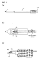
- Figure 1 is a view showing a structure of a specimen-holding member (microgrid having a plurality of openings) used in each embodiment of the present invention.
- Figure 1 shows a microgrid; however, a member having a plurality of openings, such as a mesh, may be used.
- any specimen-holding member may be used as long as it can hold the liquid in the openings with the help of the surface-tension of the liquid when an ionic liquid having a specimen charged thereto is supplied dropwise to the specimen-holding member.
- Figure 1a is a schematic view of a microgrid, which is a specimen-holding member having openings, which hold a specimen to be led in a specimen chamber and through which an electron beam passes. A plurality of openings are formed in a thin film made of an organic polymer, such as a collodion film.
- Figure 1b is a schematic view showing an ionic liquid dispersed in the microgrid, more specifically, an ionic liquid dispersed in the openings of the microgrid.
- Figure 1c shows a transmission electron image actually observed through a scanning electron microscope by dispersing an ionic liquid in the microgrid. In this figure, an opening of the microgrid holding an ionic liquid and an opening holding no ionic liquid are observed.
- the ionic liquid used in the present invention is, for example, 1-Butyl-3-methylimidazolium Tetrafluoroborate.
- FIG. 2 is a view showing a schematic structure of a transmission electron microscope according to a first embodiment of the invention and equipped with an ionic-liquid injection mechanism.
- an electron beam 2 which is emitted from an electron gun 1 of an electron microscope main body, is applied to specimen 9 held by a specimen holder 5 by an irradiation lens 3a and 3b.
- Reference numerals 4a and 4b indicate specimen-stage driving mechanisms of the specimen holder 5, which control the driving of the specimen holder 5 in the X-direction and in the Y direction, respectively.
- the electron beam 3 transmitted though the specimen 9 held by the specimen holder 5 is magnified by a magnification lens system and projected to an imaging apparatus 8 such as a CCD camera.
- the magnification lens system consists of an objective lens 6a, an intermediate lens 6b and a projection lens 6c.
- the specimen holder 5 can be rotated by a specimen rotation motor 16 by way of a power source for motor 15.
- a specimen-holding member (the tip portion of the specimen holder 5) 17 is constructed so as to rotate by the specimen-stage driving mechanisms.
- a specimen is rotated about the optical axis of an electron beam to enable multidirectional observation of the specimen.
- serial images are taken while rotating, reconstituted and subjected to electron beam tomography, a three dimensional structure of a specimen can be also observed.
- an ionic liquid is injected into the specimen-holding member 17.
- the ionic liquid stored in the liquid vessel 10 is injected by a liquid feed pump 11 into the specimen holder 5 through a capillary tube 12.
- a valve 13 is provided to the capillary tube 12.
- injection of an ionic liquid into the specimen holder 5 is controlled.
- the driving of the liquid feed pump 11 and the valve 13 is controlled by an ionic-liquid amount controlling unit 14.
- Figure 3 is a view showing a structure of an ionic-liquid injection (introduction) mechanism provided to the specimen holder 5.
- Figure 3a shows appearance of the specimen holder 5 having the ionic-liquid injection mechanism.
- a specimen 9 is placed in the opening of the tip portion.
- Figure 3b is an enlarged view of the tip portion of the specimen holder 5.
- a specimen rotation motor 16 is connected to the specimen-holding member 17, for enabling the specimen-holding member 17 to rotate.
- an ionic liquid is injected into the specimen-holding member 17 by the capillary tube 12.
- a thin metal line processed in the form of loop is used, which may be detachably attached like a cartridge.
- the amount of ionic liquid is controlled to an optimal level sufficient to allow an electron beam to pass while directly observing the dispersion state of the ionic liquid in the specimen-holding member by a transmission electron microscope.
- the specimen-holding member 17 can be rotated by the specimen-stage driving mechanisms, a specimen is rotated about the optical axis of an electron beam to enable multidirectional observation of the specimen. Furthermore, if serial images are taken while rotating, reconstituted and subjected to electron beam tomography, a three dimensional structure of a specimen can be also observed.
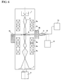
- Figure 4 is a view showing a schematic structure of a transmission electron microscope according to a second embodiment of the invention, which has a specimen holder equipped with an electrode.
- a voltage application source 20 which is connected to a specimen holder 5, is operated to apply a voltage to an ionic liquid. In this manner, an electric field is applied to a specimen 9.
- the ionic liquid introduction mechanism of the first embodiment is not shown in Figure 4 , needless to say, the mechanism may be provided.
- Figure 5 is a view showing the structure of the specimen holder 5 equipped with an electrode according to the second embodiment.
- Figure 5a shows appearance of the specimen holder 5 equipped with an electrode.
- a specimen 9 is placed in the opening of the tip portion of the specimen holder 5.
- Figure 5b is enlarged view of the tip portion of the specimen holder 5.
- the tip portion of the specimen holder 5, i.e., a specimen-holding member 17, can be rotated by a specimen rotation motor 16 connected to the member.
- the specimen-holding member 17 holding an ionic liquid is equipped with an electrode 18.
- a specimen injected in an ionic liquid and dispersed in the specimen-holding member is moved or changed in shape by voltage application. How to move and change can be directly observed by a transmission electron microscope. By use of this, for example, in a semiconductor manufacturing process, how a specimen changes can be checked. Furthermore, in the embodiment, since the specimen-holding member can be rotated by the specimen-stage driving mechanisms, a specimen is rotated about the optical axis of an electron beam to enable multidirectional observation of the specimen. Furthermore, if serial images are taken while rotating, reconstituted and subjected to electron beam tomography, a three dimensional structure of a specimen can be also observed.
- Figure 6 is a view showing a schematic structure of a transmission electron microscope according to the third embodiment of the invention, which is equipped with a specimen charge mechanism by evaporation.
- an evaporation power source 21 is connected to a specimen holder 5 so as to charge a specimen into an ionic liquid by evaporation.
- the ionic liquid introduction mechanism according to the first embodiment may be provided.
- Figure 7 shows a structure of the specimen holder 5 having the specimen charge mechanism by evaporation, according to the third embodiment.
- Figure 7a shows appearance of the specimen holder 5 having the specimen charge mechanism by evaporation.
- a specimen 9 is placed in the opening of the tip portion.
- Figure 7b is an enlarged view of the tip portion of the specimen holder 5.
- the tip portion of the specimen holder 5, i.e., a specimen-holding member 17, can be rotated by a specimen rotation motor 16 connected to the member.
- an evaporation heater 19 is provided in the proximity of the specimen-holding member 17 holding an ionic liquid.
- a material to be evaporated set on the evaporation heater 19 such as palladium and platinum (referred to as metal M) is melted on the evaporation heater 19, when heated by supplying a current by the evaporation power source 21 and microparticles thereof are charged into an ionic liquid.
- the shape of evaporated metal microparticles in an ionic liquid and how microparticles are evaporated and charged into an ionic liquid can be directly observed by a transmission electron microscope.
- the strength of materials constituting a micro region of a specimen and compatibility between the materials (ions) can be analyzed.
- the specimen-holding member can be rotated by the specimen-stage driving mechanisms, a specimen is rotated about the optical axis of an electron beam to enable multidirectional observation of the specimen. Furthermore, if serial images are taken while rotating, reconstituted and subjected to electron beam tomography, a three dimensional structure of a specimen can be also observed.
- Figure 8 is a view showing a schematic structure of a transmission electron microscope according to a fourth embodiment of the invention, which has an ionic liquid and reaction-solution introduction (injection) mechanisms.
- an ionic liquid and a reaction solution can be injected respectively by independent ionic-liquid and reaction-solution introduction mechanisms connected to a specimen holder 5 while independently controlling the injection amounts.
- the ionic liquid and reaction solution are stored in liquid vessels 10a and 10b, injected into the specimen holder 5 respectively by means of liquid feed pumps 11a and 11b by way of respective capillary tubes (microcapillary) 12a and 12b.
- capillary tubes 12a and 12b respectively feeding an ionic liquid and the reaction solution.
- valves 13a and 13b are provided respectively. Injection of the ionic liquid and reaction solution to the specimen holder 5 is controlled by the function of the valves 13a and 13b.
- Driving of the liquid feed pumps 11a and 11b and the valves 13a and 13b is controlled by ionic liquid and reaction-solution amount controlling units 14a and 14b.
- Figure 9 shows a structure of the specimen holder 5 according to the fourth embodiment, which has ionic liquid and reaction-solution introduction mechanisms.
- Figure 9a shows appearance of the specimen holder 5 having the ionic liquid and reaction solution injection mechanisms.
- a specimen 9 is placed in the opening of the tip portion.
- Figure 9b shows an enlarged view of the tip portion of the specimen holder 5.
- a specimen-holding member 17 can be rotated by a specimen rotation motor 16 connected to the member.
- the ionic liquid and reaction solution are injected by the respective liquid-feed capillary tubes 12a and 12b into the specimen-holding member 17.
- a thin metal line processed in the form of loop is used, which may be detachably attached like a cartridge.
- a mechanism for introducing a liquid-state specimen, a solution containing a powder specimen dissolved therein or a reagent solution, for example, a microcapillary is provided to charge a liquid specimen into an ionic liquid.
- an enzyme is introduced as a specimen, an enzyme reaction can be directly observed by an electron microscope.
- a specimen which is an antibody having an antigen dispersed therein, is introduced, how to react with a reagent, in other words, an antigen-antibody reaction, can be directly observed by an electron microscope.
- the specimen holding member can be rotated by the specimen-stage driving mechanisms, a specimen is rotated about the optical axis of an electron beam to enable multidirectional observation of the specimen. Furthermore, if serial images are taken while rotating, reconstituted and subjected to electron beam tomography, a three dimensional structure of a specimen can be also observed.
- an ionic liquid is used as a dispersion medium to allow a specimen to suspend therein to observe the specimen without deformation.
- a mechanism for injecting an ionic liquid is provided in the proximity of a specimen-holding member. By virtue of this, the injection amount of ionic liquid is controlled. Furthermore, whether the injection amount of ionic liquid is optimum or not can be checked while observing an electron microscopic image. Therefore, the thickness of a film serving as a specimen support film can be controlled without fail.
- an electrode is provided in the proximity of a specimen-holding member.
- a specimen can be moved by supplying a current, and a phenomenon thereof can be directly observed by an electron microscope.
- an evaporation apparatus is provided in the proximity of a specimen-holding member.
- metal microparticles are introduced by evaporation in an ionic liquid to allow direct observation of microparticles and evaporation phenomenon by an electron microscope.
- a mechanism for introducing a liquid-state specimen, a solution containing a powder specimen dissolved therein or a reagent solution, for example, a microcapillary, is provided in the proximity of a specimen-holding member.
- a liquid specimen can be charged into an ionic liquid.
- an enzyme is introduced as a specimen, an enzyme reaction can be directly observed by an electron microscope.
- an antibody in the case of a specimen having an antigen dispersed therein, how to react with the reagent, in other words, an antigen-antibody reaction, can be directly observed by an electron microscope.
- a specimen holding member can be rotated by specimen-stage driving mechanisms, a specimen is rotated about the optical axis of an electron beam to enable multidirectional observation of the specimen. Furthermore, if serial images are taken while rotating, reconstituted and subjected to electron beam tomography, a three dimensional structure of a specimen can be also observed.
Landscapes
- Chemical & Material Sciences (AREA)
- Analytical Chemistry (AREA)
- Physics & Mathematics (AREA)
- Health & Medical Sciences (AREA)
- Life Sciences & Earth Sciences (AREA)
- Biochemistry (AREA)
- General Health & Medical Sciences (AREA)
- General Physics & Mathematics (AREA)
- Immunology (AREA)
- Pathology (AREA)
- Sampling And Sample Adjustment (AREA)
- Analysing Materials By The Use Of Radiation (AREA)
Abstract
Description
- The present invention relates to a transmission electron microscope and a method for observing a specimen.
- When a specimen is observed by a transmission electron microscope, a specimen to be observed is spread by use of a dispersion medium, such as water and an alcohol on a plastic support film such as a collodion film.
- Conventional pretreatment methods for a specimen to be subjected to observation and specimen holding methods are as follows. For example, as shown in
Patent Document 1, to observe a scanned electron microscopic image in a wet environment, there is a method of providing a partition to a specimen holding unit to prevent breakage of the specimen and controlling application of pressure. Furthermore, as shown inPatent Document 2, in a process of reducing the thickness of a powder specimen by a FIB process, there is a method of providing a recess in a plate-form specimen-holding substrate, thereby reducing the amount of embedding agent for holding the specimen and reducing the FIB process time. Moreover, as shown in Patent Document 3, when a powder specimen is observed by a transmission electron microscope, there is a method of sprinkling the powder specimen by means of vibration of a vibrator such that the specimen is sufficiently dispersed and deposited onto a collodion film. - [Patent Document 1]
JP Patent Publication (Kohyo) No. 2005-529340A - [Patent Document 2]
JP Patent Publication (Kokai) No. 11-30575A 1999 - [Patent Document 3]
JP Patent Publication (Kokai) No. 49-103565A 1974 - However, in any one of the methods of Patent Documents, deformation of a specimen cannot be avoided and a specimen in motion cannot be observed.
- To describe more specifically, a support film is a thin organic polymer film sufficient to allow an electron beam to pass; however, it is a solid. Therefore, a specimen placed on the film deforms by its weight or deforms during a drying process before it is set in an electron microscope, with the result that a correct shape of the specimen cannot be observed.
- Furthermore, since the interior of an electron microscope is maintained in vacuum, a specimen to be observed must be dried such that it can be observed under vacuum. Therefore, a specimen containing water, such as a biological specimen, is dewatered by use of an organic solvent such as an alcohol before it is set within the microscope. However, denaturation and deformation occur at that time. Thus, it is impossible to observe a shape thereof as close as an original shape present in nature.
- Moreover, in the case of a micro-particulate specimen such as an extracted virus or a protein particle, sometimes, the specimen is momentarily frozen, embedded in amorphous ice and subjected to observation. However, since the specimen is embedded in solid ice, movement of the specimen cannot be observed.
- The shape of a specimen and the function thereof are closely related with each other. Therefore, to elucidate the function of the specimen, the shape as is in nature is preferably observed. Accordingly, it has been desired to develop an observation method for a specimen without deformation.
- The present invention was made in the above circumstances and provides means which enables observation of a natural shape of a specimen without deformation.
- To solve the problem, in the present invention, an ionic liquid is held in a specimen-holding member having an opening (for example, a microgrid and a mesh) and a specimen is charged to the ionic liquid to allow a specimen to suspend and then observed. Furthermore, in the proximity of the specimen-holding member, a mechanism of injecting an ionic liquid (an ionic-liquid introduction mechanism) and/or an electrode are provided. When a voltage is applied to the electrode, the specimen moves and deforms in the ionic liquid. In this manner, how a specimen moves and deforms can be observed. Furthermore, in the proximity of the specimen-holding member, an evaporation apparatus is provided to charge a specimen into the ionic liquid while evaporating. Moreover, in the proximity of the specimen-holding member, a microcapillary is provided to charge a liquid-state specimen into the ionic liquid. Note that the specimen-holding member is designed to be rotatable.
- More specifically, in a transmission electron microscope according to the present invention, an electron beam is applied to a specimen set in a specimen chamber and an image of the specimen is formed from the electron beam transmitted through the specimen. The transmission electron microscope has a specimen holder and an image forming unit for forming a specimen image based on the electron beam transmitted through the specimen. The specimen holder herein is used for introducing a specimen into a specimen chamber. The tip portion thereof, i.e., a specimen-holding member, has an opening for transmitting an electron beam and holding the ionic liquid having a specimen charged. A specimen is introduced into the opening of the specimen-holding member by a liquid introduction mechanism for introducing an ionic liquid. Note that, the amount of ionic liquid to be introduced is controlled by a liquid introduction-amount controlling unit.
- A transmission electron microscope according to the present invention further has voltage application means which applies a voltage to a specimen in the ionic liquid held in the opening of the specimen-holding member. Alternatively, the transmission electron microscope may have specimen evaporation means which evaporates a specimen by heating to charge the specimen into an ionic liquid.
- The liquid introduction means may be constructed such that any one of a liquid-state specimen, a solution containing a powder specimen dissolved therein and a reagent specimen solution and an ionic liquid are independently introduced into the opening of the specimen-holding member.
- The aforementioned transmission electron microscope may be constructed such that a specimen is observed while rotating the specimen-holding member.
- The specimen observation method according to the present invention is a method for observing a specimen image by applying an electron beam to a specimen set in a specimen chamber and forming the specimen image from the electron beam transmitted through the specimen. This method includes a step of introducing an ionic liquid having a specimen dispersed therein into the tip portion of a specimen holder, i.e., a specimen-holding member, for introducing the specimen into a specimen chamber, a step of applying an electron beam to an ionic liquid, and a step of observing a specimen image formed based on the electron beam transmitted through the specimen.
- In the step of introducing an ionic liquid, the specimen holder is set in the specimen chamber and thereafter the ionic liquid is introduced by use of the liquid introduction mechanism into the opening of the specimen-holding member. At this time, the amount of ionic liquid to be introduced may be controlled by the liquid introduction-amount controlling unit.
- The method for observing a specimen further includes a step of applying a voltage to the specimen in an ionic liquid held in the opening of the specimen-holding member.
- Note that in the step of introducing an ionic liquid, the ionic liquid may be introduced into the specimen-holding member and subsequently a specimen is heated to evaporate and charged in the ionic liquid.
- Furthermore, in the step of introducing an ionic liquid, after the specimen holder is set in the specimen chamber, any one of a liquid-state specimen, a solution containing a powder specimen dissolved therein and a reagent specimen solution and an ionic liquid may be independently introduced into an opening of the specimen-holding member by use of the liquid introduction mechanism.
- Furthermore, in the step of applying an electron beam, the electron beam may be applied to a specimen while the specimen-holding member is rotated by use of the specimen-holding member driving mechanism.
- Further characteristics of the present invention will be clearly described in Best Mode for Carrying Out of the Invention below and the accompanying drawings.
- According to the present invention, it is possible to observe a natural shape of a specimen without deforming. Note that, when a voltage is applied to a specimen, the specimen in motion or the specimen deformed can be observed.
-
-
Figure 1 is a view showing a structure of a specimen-holding member (microgrid) used in each embodiment of the present invention. -
Figure 2 is a view showing a schematic structure of a transmission electron microscope according to the first embodiment of the invention. -
Figure 3 is a view showing a structure of a specimen holder equipped with an ionic liquid introduction mechanism according to the first embodiment. -
Figure 4 is a view showing a schematic structure of a transmission electron microscope according to the second embodiment of the invention. -
Figure 5 is a view showing the structure of a specimen holder equipped with an electrode according to the second embodiment. -
Figure 6 is a view showing a schematic structure of a transmission electron microscope according to the third embodiment of the invention. -
Figure 7 is a view showing a structure of specimen holder equipped with a specimen charge mechanism by evaporation according to the third embodiment. -
Figure 8 is a view showing a schematic structure of a transmission electron microscope according to the fourth embodiment of the invention. -
Figure 9 is a view showing a structure of a specimen holder equipped with an ionic-liquid and reaction-solution introduction mechanism according to the fourth embodiment. - 1...Electron gun, 2...Electron beam, 3a...Illumination lens (1), 3b...illumination lens (2), 4a...Specimen-stage driving mechanism (X direction), 4b...Specimen-stage driving mechanism (Y direction), 5...Specimen holder , 6a...Objective lens, 6b...Intermediate lens , 7...Fluorescent plate, 8...Imaging apparatus such as a CCD camera, 9...Specimen , 10...Liquid vessel, 10a...Vessel for ionic liquid, 10b...Vessel for reaction solution, 11...Liquid feed pump , 11a...Ionic-liquid feed pump, 11b...Reaction-solution feed pump, 12...Capillary tube (microcapillary), 12a...Capillary tube (microcapillary) for feeding ionic liquid, 12b...Capillary tube (microcapillary) for feeding a reaction solution, 13...valve, 13a...valve for ionic liquid, 13b...valve for reaction solution, 14...liquid-amount controlling unit, 14a...Ionic-liquid amount controlling unit, 14b...Liquid-amount controlling unit for reaction solution, 15...Power source for motor, 16...Specimen rotation motor, 17...Specimen-holding member, 18...Electrode , 18a...Anode, 18b...Cathode, 19...Evaporation heater, 20...Voltage application source, 21...Evaporation power source
- The present invention relates to a transmission electron microscope by which a specimen allowed to suspend in a liquid can be observed by allowing a specimen holding member to hold an ionic liquid having the specimen charged thereto, and a method for observing a specimen by using the same.
- Referring to the accompanying drawings, the embodiments of the present invention will be described below. It should be noted that the each of the embodiments is merely an example of realizing the present invention and will not limit the technical range of the present invention. Furthermore, in the drawings, like reference numerals are used to designate like structural elements.
-
Figure 1 is a view showing a structure of a specimen-holding member (microgrid having a plurality of openings) used in each embodiment of the present invention.Figure 1 shows a microgrid; however, a member having a plurality of openings, such as a mesh, may be used. In other words, any specimen-holding member may be used as long as it can hold the liquid in the openings with the help of the surface-tension of the liquid when an ionic liquid having a specimen charged thereto is supplied dropwise to the specimen-holding member. -
Figure 1a is a schematic view of a microgrid, which is a specimen-holding member having openings, which hold a specimen to be led in a specimen chamber and through which an electron beam passes. A plurality of openings are formed in a thin film made of an organic polymer, such as a collodion film.Figure 1b is a schematic view showing an ionic liquid dispersed in the microgrid, more specifically, an ionic liquid dispersed in the openings of the microgrid. Furthermore,Figure 1c shows a transmission electron image actually observed through a scanning electron microscope by dispersing an ionic liquid in the microgrid. In this figure, an opening of the microgrid holding an ionic liquid and an opening holding no ionic liquid are observed. Note that the ionic liquid used in the present invention is, for example, 1-Butyl-3-methylimidazolium Tetrafluoroborate. -
Figure 2 is a view showing a schematic structure of a transmission electron microscope according to a first embodiment of the invention and equipped with an ionic-liquid injection mechanism. As shown inFigure 2 , anelectron beam 2, which is emitted from anelectron gun 1 of an electron microscope main body, is applied tospecimen 9 held by aspecimen holder 5 by anirradiation lens Reference numerals specimen holder 5, which control the driving of thespecimen holder 5 in the X-direction and in the Y direction, respectively. The electron beam 3 transmitted though thespecimen 9 held by thespecimen holder 5 is magnified by a magnification lens system and projected to animaging apparatus 8 such as a CCD camera. The magnification lens system consists of anobjective lens 6a, anintermediate lens 6b and aprojection lens 6c. Thespecimen holder 5 can be rotated by aspecimen rotation motor 16 by way of a power source formotor 15. - In the embodiment, a specimen-holding member (the tip portion of the specimen holder 5) 17 is constructed so as to rotate by the specimen-stage driving mechanisms. By virtue of the mechanisms, a specimen is rotated about the optical axis of an electron beam to enable multidirectional observation of the specimen. Furthermore, if serial images are taken while rotating, reconstituted and subjected to electron beam tomography, a three dimensional structure of a specimen can be also observed.
- Furthermore, in the embodiment, from the ionic-liquid injection mechanism connected to the
specimen holder 5, an ionic liquid is injected into the specimen-holdingmember 17. The ionic liquid stored in theliquid vessel 10 is injected by aliquid feed pump 11 into thespecimen holder 5 through acapillary tube 12. To thecapillary tube 12, avalve 13 is provided. By the function of thevalve 13, injection of an ionic liquid into thespecimen holder 5 is controlled. The driving of theliquid feed pump 11 and thevalve 13 is controlled by an ionic-liquidamount controlling unit 14. -
Figure 3 is a view showing a structure of an ionic-liquid injection (introduction) mechanism provided to thespecimen holder 5.Figure 3a shows appearance of thespecimen holder 5 having the ionic-liquid injection mechanism. Aspecimen 9 is placed in the opening of the tip portion. Furthermore,Figure 3b is an enlarged view of the tip portion of thespecimen holder 5. To the specimen-holdingmember 17, aspecimen rotation motor 16 is connected for enabling the specimen-holdingmember 17 to rotate. Furthermore, as shown inFigure 3c , an ionic liquid is injected into the specimen-holdingmember 17 by thecapillary tube 12. As the specimen-holdingmember 17, a thin metal line processed in the form of loop is used, which may be detachably attached like a cartridge. - Note that, in the embodiment, the amount of ionic liquid is controlled to an optimal level sufficient to allow an electron beam to pass while directly observing the dispersion state of the ionic liquid in the specimen-holding member by a transmission electron microscope.
- As described above, in the embodiment, since the specimen-holding
member 17 can be rotated by the specimen-stage driving mechanisms, a specimen is rotated about the optical axis of an electron beam to enable multidirectional observation of the specimen. Furthermore, if serial images are taken while rotating, reconstituted and subjected to electron beam tomography, a three dimensional structure of a specimen can be also observed. -
Figure 4 is a view showing a schematic structure of a transmission electron microscope according to a second embodiment of the invention, which has a specimen holder equipped with an electrode. In this embodiment, unlike the first embodiment, avoltage application source 20, which is connected to aspecimen holder 5, is operated to apply a voltage to an ionic liquid. In this manner, an electric field is applied to aspecimen 9. Furthermore, although the ionic liquid introduction mechanism of the first embodiment is not shown inFigure 4 , needless to say, the mechanism may be provided. -
Figure 5 is a view showing the structure of thespecimen holder 5 equipped with an electrode according to the second embodiment.Figure 5a shows appearance of thespecimen holder 5 equipped with an electrode. Aspecimen 9 is placed in the opening of the tip portion of thespecimen holder 5.Figure 5b is enlarged view of the tip portion of thespecimen holder 5. The tip portion of thespecimen holder 5, i.e., a specimen-holdingmember 17, can be rotated by aspecimen rotation motor 16 connected to the member. Furthermore, as shown inFigure 5c , the specimen-holdingmember 17 holding an ionic liquid is equipped with an electrode 18. - By virtue of the structure as mentioned above, in the embodiment, a specimen injected in an ionic liquid and dispersed in the specimen-holding member is moved or changed in shape by voltage application. How to move and change can be directly observed by a transmission electron microscope. By use of this, for example, in a semiconductor manufacturing process, how a specimen changes can be checked. Furthermore, in the embodiment, since the specimen-holding member can be rotated by the specimen-stage driving mechanisms, a specimen is rotated about the optical axis of an electron beam to enable multidirectional observation of the specimen. Furthermore, if serial images are taken while rotating, reconstituted and subjected to electron beam tomography, a three dimensional structure of a specimen can be also observed.
-
Figure 6 is a view showing a schematic structure of a transmission electron microscope according to the third embodiment of the invention, which is equipped with a specimen charge mechanism by evaporation. - In the embodiment, unlike from the first embodiment, an
evaporation power source 21 is connected to aspecimen holder 5 so as to charge a specimen into an ionic liquid by evaporation. Also in this embodiment, the ionic liquid introduction mechanism according to the first embodiment may be provided. -
Figure 7 shows a structure of thespecimen holder 5 having the specimen charge mechanism by evaporation, according to the third embodiment.Figure 7a shows appearance of thespecimen holder 5 having the specimen charge mechanism by evaporation. Aspecimen 9 is placed in the opening of the tip portion.Figure 7b is an enlarged view of the tip portion of thespecimen holder 5. The tip portion of thespecimen holder 5, i.e., a specimen-holdingmember 17, can be rotated by aspecimen rotation motor 16 connected to the member. Furthermore, as shown inFigure 7c , anevaporation heater 19 is provided in the proximity of the specimen-holdingmember 17 holding an ionic liquid. A material to be evaporated set on theevaporation heater 19 such as palladium and platinum (referred to as metal M) is melted on theevaporation heater 19, when heated by supplying a current by theevaporation power source 21 and microparticles thereof are charged into an ionic liquid. - In the embodiment, the shape of evaporated metal microparticles in an ionic liquid and how microparticles are evaporated and charged into an ionic liquid can be directly observed by a transmission electron microscope. By virtue of this, the strength of materials constituting a micro region of a specimen and compatibility between the materials (ions) can be analyzed.
- Furthermore, in the embodiment, since the specimen-holding member can be rotated by the specimen-stage driving mechanisms, a specimen is rotated about the optical axis of an electron beam to enable multidirectional observation of the specimen. Furthermore, if serial images are taken while rotating, reconstituted and subjected to electron beam tomography, a three dimensional structure of a specimen can be also observed.
-
Figure 8 is a view showing a schematic structure of a transmission electron microscope according to a fourth embodiment of the invention, which has an ionic liquid and reaction-solution introduction (injection) mechanisms. - In the embodiment, an ionic liquid and a reaction solution can be injected respectively by independent ionic-liquid and reaction-solution introduction mechanisms connected to a
specimen holder 5 while independently controlling the injection amounts. To describe more specifically, the ionic liquid and reaction solution are stored inliquid vessels specimen holder 5 respectively by means of liquid feed pumps 11a and 11b by way of respective capillary tubes (microcapillary) 12a and 12b. To thecapillary tubes valves specimen holder 5 is controlled by the function of thevalves valves amount controlling units -
Figure 9 shows a structure of thespecimen holder 5 according to the fourth embodiment, which has ionic liquid and reaction-solution introduction mechanisms.Figure 9a shows appearance of thespecimen holder 5 having the ionic liquid and reaction solution injection mechanisms. Aspecimen 9 is placed in the opening of the tip portion.Figure 9b shows an enlarged view of the tip portion of thespecimen holder 5. A specimen-holdingmember 17 can be rotated by aspecimen rotation motor 16 connected to the member. Furthermore, as shown inFigure 9c , the ionic liquid and reaction solution are injected by the respective liquid-feed capillary tubes member 17. As the specimen-holdingmember 17 herein, a thin metal line processed in the form of loop is used, which may be detachably attached like a cartridge. - In the embodiment, in the proximity of the specimen-holding member, a mechanism for introducing a liquid-state specimen, a solution containing a powder specimen dissolved therein or a reagent solution, for example, a microcapillary, is provided to charge a liquid specimen into an ionic liquid. At this time, if an enzyme is introduced as a specimen, an enzyme reaction can be directly observed by an electron microscope. Alternatively, if a specimen, which is an antibody having an antigen dispersed therein, is introduced, how to react with a reagent, in other words, an antigen-antibody reaction, can be directly observed by an electron microscope. In the embodiment, since the specimen holding member can be rotated by the specimen-stage driving mechanisms, a specimen is rotated about the optical axis of an electron beam to enable multidirectional observation of the specimen. Furthermore, if serial images are taken while rotating, reconstituted and subjected to electron beam tomography, a three dimensional structure of a specimen can be also observed.
- According to embodiments of the present invention, in a transmission electron microscope, an ionic liquid is used as a dispersion medium to allow a specimen to suspend therein to observe the specimen without deformation.
- Furthermore, a mechanism for injecting an ionic liquid is provided in the proximity of a specimen-holding member. By virtue of this, the injection amount of ionic liquid is controlled. Furthermore, whether the injection amount of ionic liquid is optimum or not can be checked while observing an electron microscopic image. Therefore, the thickness of a film serving as a specimen support film can be controlled without fail.
- Furthermore, an electrode is provided in the proximity of a specimen-holding member. By virtue of this, a specimen can be moved by supplying a current, and a phenomenon thereof can be directly observed by an electron microscope.
- Furthermore, an evaporation apparatus is provided in the proximity of a specimen-holding member. By virtue of this, metal microparticles are introduced by evaporation in an ionic liquid to allow direct observation of microparticles and evaporation phenomenon by an electron microscope.
- A mechanism for introducing a liquid-state specimen, a solution containing a powder specimen dissolved therein or a reagent solution, for example, a microcapillary, is provided in the proximity of a specimen-holding member. By virtue of this, a liquid specimen can be charged into an ionic liquid. At this time, if an enzyme is introduced as a specimen, an enzyme reaction can be directly observed by an electron microscope. Alternatively, if an antibody, in the case of a specimen having an antigen dispersed therein, how to react with the reagent, in other words, an antigen-antibody reaction, can be directly observed by an electron microscope.
- Since a specimen holding member can be rotated by specimen-stage driving mechanisms, a specimen is rotated about the optical axis of an electron beam to enable multidirectional observation of the specimen. Furthermore, if serial images are taken while rotating, reconstituted and subjected to electron beam tomography, a three dimensional structure of a specimen can be also observed.
Claims (14)
- A transmission electron microscope in which an electron beam is applied to a specimen set in a specimen chamber and an image of the specimen is formed from the electron beam transmitted through the specimen, comprising
a specimen holder for introducing the specimen into the specimen chamber, having a specimen holding member at the tip portion, which has an opening for transmitting the electron beam and for holding an ionic liquid having the specimen charged therein, and
an image forming unit for forming an image of the specimen based on the electron beam transmitted through the specimen. - The transmission electron microscope according to claim 1, further comprising a liquid introduction mechanism for introducing the ionic liquid into the opening of the specimen-holding member.
- The transmission electron microscope according to claim 2, further comprising a liquid introduction-amount controlling unit for controlling an introduction amount of the ionic liquid.
- The transmission electron microscope according to claim 1, further comprising voltage application means which applies a voltage to the specimen in the ionic liquid held in an opening of the specimen-holding member.
- The transmission electron microscope according to claim 1, further comprising specimen evaporation means which evaporates the specimen by heating and charges the specimen in the ionic liquid.
- The transmission electron microscope according to claim 1, further comprising a liquid introduction mechanism for independently introducing any one of a liquid-state specimen, a solution containing a powder specimen dissolved therein and a reagent specimen solution, and the ionic liquid.
- The transmission electron microscope according to claim 1, further comprising a specimen-holding member driving mechanism for rotating the specimen-holding member.
- A method for observing a specimen in which an electron beam is applied to a specimen set in a specimen chamber and a specimen image formed from the electron beam transmitted through the specimen is observed, comprising
a step of introducing an ionic liquid having the specimen dispersed therein into a specimen-holding member at the tip potion of a specimen holder for introducing the specimen to the specimen chamber,
a step of applying an electron beam to the ionic liquid, and
a step of observing a specimen image formed based on the electron beam transmitted through the specimen. - The method for observing a specimen according to claim 8, wherein, in the step of introducing an ionic liquid, the specimen holder is set in the specimen chamber, and thereafter, the ionic liquid is introduced in an opening of the specimen-holding member by use of a liquid introduction mechanism.
- The method for observing a specimen according to claim 9, wherein the ionic liquid introduction amount is controlled by a liquid introduction-amount controlling unit.
- The method for observing a specimen according to claim 8, further comprising the step of applying a voltage to the specimen in the ionic liquid contained in the opening of the specimen-holding member.
- The method for observing a specimen according to claim 8, wherein, in the step of introducing an ionic liquid, the ionic liquid is introduced into the specimen-holding member and subsequently the specimen is evaporated by heating and charged into the ionic liquid.
- The method for observing a specimen according to claim 8, wherein, in the step of introducing an ionic liquid, the specimen holder is set in the specimen chamber, and thereafter, any one of a liquid-state specimen, a solution containing a powder specimen dissolved therein and a reagent specimen solution, and the ionic liquid are independently introduced in an opening of the specimen-holding member by use of the liquid introduction mechanism.
- The method for observing a specimen according to claim 8, wherein, in the step of applying an electron beam, the electron beam is applied to the specimen while the specimen-holding member is rotated by use of a specimen-holding member driving mechanism.
Priority Applications (1)
| Application Number | Priority Date | Filing Date | Title |
|---|---|---|---|
| EP14002375.5A EP2801998B1 (en) | 2008-04-28 | 2009-04-27 | Transmission electron microscope, and method of observing specimen |
Applications Claiming Priority (2)
| Application Number | Priority Date | Filing Date | Title |
|---|---|---|---|
| JP2008117547A JP5226378B2 (en) | 2008-04-28 | 2008-04-28 | Transmission electron microscope and sample observation method |
| PCT/JP2009/058261 WO2009133842A1 (en) | 2008-04-28 | 2009-04-27 | Transmission electron microscope, and method of observing specimen |
Related Child Applications (2)
| Application Number | Title | Priority Date | Filing Date |
|---|---|---|---|
| EP14002375.5A Division-Into EP2801998B1 (en) | 2008-04-28 | 2009-04-27 | Transmission electron microscope, and method of observing specimen |
| EP14002375.5A Division EP2801998B1 (en) | 2008-04-28 | 2009-04-27 | Transmission electron microscope, and method of observing specimen |
Publications (3)
| Publication Number | Publication Date |
|---|---|
| EP2273528A1 true EP2273528A1 (en) | 2011-01-12 |
| EP2273528A4 EP2273528A4 (en) | 2014-04-23 |
| EP2273528B1 EP2273528B1 (en) | 2015-03-11 |
Family
ID=41255058
Family Applications (2)
| Application Number | Title | Priority Date | Filing Date |
|---|---|---|---|
| EP09738779.9A Active EP2273528B1 (en) | 2008-04-28 | 2009-04-27 | Transmission electron microscope, and method of observing specimen |
| EP14002375.5A Not-in-force EP2801998B1 (en) | 2008-04-28 | 2009-04-27 | Transmission electron microscope, and method of observing specimen |
Family Applications After (1)
| Application Number | Title | Priority Date | Filing Date |
|---|---|---|---|
| EP14002375.5A Not-in-force EP2801998B1 (en) | 2008-04-28 | 2009-04-27 | Transmission electron microscope, and method of observing specimen |
Country Status (4)
| Country | Link |
|---|---|
| US (2) | US8785883B2 (en) |
| EP (2) | EP2273528B1 (en) |
| JP (1) | JP5226378B2 (en) |
| WO (1) | WO2009133842A1 (en) |
Cited By (2)
| Publication number | Priority date | Publication date | Assignee | Title |
|---|---|---|---|---|
| CN106018851A (en) * | 2016-05-23 | 2016-10-12 | 济南大学 | Method for preparing steroid immunosensor based on sheet black phosphorus and application |
| CN109444195A (en) * | 2018-12-27 | 2019-03-08 | 中建材蚌埠玻璃工业设计研究院有限公司 | A kind of preparation method of the scanning electron microscope sample of nanoscale barium titanate powder |
Families Citing this family (26)
| Publication number | Priority date | Publication date | Assignee | Title |
|---|---|---|---|---|
| JP4799690B2 (en) * | 2009-12-01 | 2011-10-26 | 国立大学法人北海道大学 | Liquid medium for sample observation by electron microscope and sample observation method by electron microscope using the same |
| JP5442417B2 (en) * | 2009-12-14 | 2014-03-12 | 株式会社日立ハイテクノロジーズ | Charged particle beam apparatus and sample observation method |
| JP2011216426A (en) * | 2010-04-02 | 2011-10-27 | Hitachi High-Technologies Corp | Sample holder and sample observation method |
| JP5707082B2 (en) * | 2010-10-08 | 2015-04-22 | 株式会社日立ハイテクノロジーズ | Scanning electron microscope observation method for a sample floating on the surface of a liquid |
| EP2755225B1 (en) * | 2011-09-09 | 2017-05-10 | Japan Science and Technology Agency | Electron-microscopic examination method for examining a living biological sample |
| JP5951223B2 (en) * | 2011-11-02 | 2016-07-13 | 株式会社日立ハイテクノロジーズ | Electron microscopy, electron microscope and observation specimen preparation device |
| JP5723801B2 (en) | 2012-02-06 | 2015-05-27 | 株式会社日立ハイテクノロジーズ | Charged particle beam apparatus and wiring method |
| US9086343B2 (en) * | 2012-03-09 | 2015-07-21 | Hitachi High-Technologies Corporation | Methods for observing samples and preprocessing thereof |
| EP2639568A1 (en) | 2012-03-16 | 2013-09-18 | Stichting Dutch Polymer Institute | Observation method by TEM or SEM and specimen for use therein |
| US8969827B2 (en) * | 2012-07-09 | 2015-03-03 | Materials Analysis Technology (Us) Corp. | Specimen preparation for transmission electron microscopy |
| WO2014013709A1 (en) * | 2012-07-17 | 2014-01-23 | 株式会社メルビル | Specimen holder tip part, specimen holder having said specimen holder tip part, gonio stage, and electron microscope having said gonio stage |
| JP6169334B2 (en) * | 2012-07-27 | 2017-07-26 | 株式会社日立ハイテクノロジーズ | Electron microscope and electron microscope sample holder |
| JP2014092496A (en) * | 2012-11-06 | 2014-05-19 | Hitachi High-Technologies Corp | Sample observation method using ionic liquid |
| JP6126425B2 (en) * | 2013-03-27 | 2017-05-10 | 株式会社日立ハイテクサイエンス | Focused ion beam apparatus and control method thereof |
| US9244025B2 (en) * | 2013-07-05 | 2016-01-26 | Semiconductor Energy Laboratory Co., Ltd. | Transmission electron diffraction measurement apparatus and method for measuring transmission electron diffraction pattern |
| EP2838108A1 (en) * | 2013-08-12 | 2015-02-18 | Fei Company | Method of using an environmental transmission electron microscope |
| WO2015115502A1 (en) | 2014-01-29 | 2015-08-06 | 独立行政法人科学技術振興機構 | Protectant for electron microscope observation of hydrated biological sample, kit for electron microscope observation, method for observation, diagnosis, evaluation, or quantification by electron microscope, and sample stage |
| JP6569151B2 (en) * | 2015-02-25 | 2019-09-04 | 学校法人日本大学 | Observation method and sample for observation of complex by transmission electron microscope using ionic liquid |
| DE112016006464T5 (en) | 2016-03-18 | 2018-11-08 | Hitachi High-Technologies Corporation | Sample observation method |
| US11085039B2 (en) | 2016-12-12 | 2021-08-10 | xCella Biosciences, Inc. | Methods and systems for screening using microcapillary arrays |
| EP3551745A4 (en) | 2016-12-12 | 2020-07-15 | Xcella Biosciences, Inc. | METHODS AND SYSTEMS FOR SCREENING USING MICROCAPILLAR ARRAYS |
| CN110382439B (en) | 2016-12-30 | 2026-07-21 | 埃克切拉生物科学公司 | Multistage sample recovery system |
| DK3890876T3 (en) | 2018-12-06 | 2024-07-22 | Xcella Biosciences Inc | LATERAL FILLING OF MICROCAPILLAR ARRAYS |
| DE102019103551B3 (en) * | 2019-02-13 | 2020-07-30 | JOMESA Meßsysteme GmbH | Method for the analysis of a particle accumulation on a filter membrane |
| CA3156776A1 (en) | 2019-11-08 | 2021-05-14 | xCella Biosciences, Inc. | Apparatus and methods for laser-based single cell recovery from microcapillary arrays |
| EP4502699A1 (en) * | 2023-08-03 | 2025-02-05 | Leica Microsystems CMS GmbH | Computer-based methods for analyzing a plurality of images, diagnostic and medical devices, and gui |
Family Cites Families (13)
| Publication number | Priority date | Publication date | Assignee | Title |
|---|---|---|---|---|
| JPS49103565A (en) | 1973-02-05 | 1974-10-01 | ||
| JP2781320B2 (en) | 1993-01-18 | 1998-07-30 | 株式会社蛋白工学研究所 | Sample holder for electron microscope |
| JPH10247467A (en) * | 1997-03-04 | 1998-09-14 | Jeol Ltd | Sample holder |
| JPH1130575A (en) | 1997-07-10 | 1999-02-02 | Kawasaki Steel Corp | Powder sample holder for electron microscope |
| US6828566B2 (en) * | 1997-07-22 | 2004-12-07 | Hitachi Ltd | Method and apparatus for specimen fabrication |
| IL150056A0 (en) | 2002-06-05 | 2002-12-01 | Yeda Res & Dev | Low-pressure chamber for scanning electron microscopy in a wet environment |
| JP4408363B2 (en) * | 2003-10-01 | 2010-02-03 | 株式会社日立ハイテクノロジーズ | Sample holder for electron microscope and electron microscope |
| JP2005174808A (en) * | 2003-12-12 | 2005-06-30 | Jeol Ltd | Sample holder and charged particle beam apparatus |
| NL1027025C2 (en) | 2004-09-13 | 2006-03-14 | Univ Delft Tech | Microreactor for a transmission electron microscope and heating element and method for manufacturing thereof. |
| JP2007163447A (en) | 2005-12-09 | 2007-06-28 | Lee Bing Huan | Ultra-thin liquid control plate for electron microscope |
| JP2007165283A (en) * | 2005-12-09 | 2007-06-28 | Lee Bing Huan | Strip for controlling ultrathin liquid for electron microscope, and combination of same and box |
| EP1978355B1 (en) * | 2006-01-20 | 2016-07-27 | Hitachi High-Technologies Corporation | Method of observing sample using a liquid medium for preventing charge-up in an electron microscope |
| EP1868225A1 (en) * | 2006-05-29 | 2007-12-19 | FEI Company | Sample carrier and sample holder |
-
2008
- 2008-04-28 JP JP2008117547A patent/JP5226378B2/en active Active
-
2009
- 2009-04-27 US US12/918,619 patent/US8785883B2/en active Active
- 2009-04-27 EP EP09738779.9A patent/EP2273528B1/en active Active
- 2009-04-27 WO PCT/JP2009/058261 patent/WO2009133842A1/en not_active Ceased
- 2009-04-27 EP EP14002375.5A patent/EP2801998B1/en not_active Not-in-force
-
2014
- 2014-05-28 US US14/289,092 patent/US9129772B2/en active Active
Cited By (3)
| Publication number | Priority date | Publication date | Assignee | Title |
|---|---|---|---|---|
| CN106018851A (en) * | 2016-05-23 | 2016-10-12 | 济南大学 | Method for preparing steroid immunosensor based on sheet black phosphorus and application |
| CN106018851B (en) * | 2016-05-23 | 2018-01-30 | 济南大学 | A kind of preparation method and application of the steroids immunosensor based on sheet black phosphorus |
| CN109444195A (en) * | 2018-12-27 | 2019-03-08 | 中建材蚌埠玻璃工业设计研究院有限公司 | A kind of preparation method of the scanning electron microscope sample of nanoscale barium titanate powder |
Also Published As
| Publication number | Publication date |
|---|---|
| US20140264017A1 (en) | 2014-09-18 |
| WO2009133842A1 (en) | 2009-11-05 |
| US20110057100A1 (en) | 2011-03-10 |
| EP2273528A4 (en) | 2014-04-23 |
| EP2273528B1 (en) | 2015-03-11 |
| EP2801998B1 (en) | 2016-08-31 |
| JP2009266741A (en) | 2009-11-12 |
| EP2801998A2 (en) | 2014-11-12 |
| US9129772B2 (en) | 2015-09-08 |
| EP2801998A3 (en) | 2014-12-10 |
| JP5226378B2 (en) | 2013-07-03 |
| US8785883B2 (en) | 2014-07-22 |
Similar Documents
| Publication | Publication Date | Title |
|---|---|---|
| EP2801998B1 (en) | Transmission electron microscope, and method of observing specimen | |
| Weissenberger et al. | Understanding the invisible hands of sample preparation for cryo-EM | |
| Wagner et al. | Preparing samples from whole cells using focused-ion-beam milling for cryo-electron tomography | |
| Suga et al. | The atmospheric scanning electron microscope with open sample space observes dynamic phenomena in liquid or gas | |
| Miyagi et al. | High-speed atomic force microscopy shows that annexin V stabilizes membranes on the second timescale | |
| Ide et al. | An artificial lipid bilayer formed on an agarose-coated glass for simultaneous electrical and optical measurement of single ion channels | |
| US7880144B2 (en) | Liquid medium for preventing charge-up in electron microscope and method of observing sample using the same | |
| JP6143487B2 (en) | Method for making a vitrified sample for an electron microscope | |
| US11719603B2 (en) | Collecting apparatus for microscopic objects, collecting container used in collecting apparatus, and method of collecting microscopic objects | |
| EP2557588B1 (en) | Combined charged particle beam and fluorescence microscope | |
| Smith et al. | Liquid-phase electron microscopy imaging of cellular and biomolecular systems | |
| Evans et al. | Enabling direct nanoscale observations of biological reactions with dynamic TEM | |
| Denkov et al. | Nanoparticle arrays in freely suspended vitrified films | |
| JP2010002300A (en) | Sample holder, sample inspection device and sample inspecting method | |
| Lv et al. | A precise pointing nanopipette for single-cell imaging via electroosmotic injection | |
| Basak et al. | Versatile microfluidics platform for enhanced multitarget super-resolution microscopy | |
| Bharat et al. | Cryo‐Correlative Light and Electron Microscopy: Toward in situ Structural Biology | |
| Sakurai et al. | A new approach to molecular self-assembly through formation of dipeptide-based unique architectures by artificial supersaturation | |
| KR101672336B1 (en) | Correlative microscopy of light microscope and electron microscope using a work station comprising sample holder for cryogenic electron microscopy for correlative imaging detection apparatus in combination of optical microscopy and electron microscopy or correlative imaging detection including said work station | |
| Zhu et al. | Electrophoretic exclusion microscale sample preparation for cryo-EM structural determination of proteins | |
| Lim et al. | High-throughput quantitative analysis of amino acids in freeze-dried drops using time-of-flight secondary ion mass spectrometry | |
| Schaffer et al. | Cryo-FIB Lamella Milling: A Comprehensive Technique to Prepare Samples of Both Plunge-and High-pressure Frozen-hydrated Specimens for in situ Studies. | |
| Cossa et al. | Cryo-electron Microscopy to Analyze the Structure of Bacterial Amyloids In Vitro | |
| Deniaud et al. | Sample Preparation for Electron Cryo-Microscopy of Macromolecular Machines | |
| Yoshikawa et al. | Spatiotemporal Control of Formation of Dynamic Protein Fiber Assemblies via Photophysical Effects of a Focused Laser Beam |
Legal Events
| Date | Code | Title | Description |
|---|---|---|---|
| PUAI | Public reference made under article 153(3) epc to a published international application that has entered the european phase |
Free format text: ORIGINAL CODE: 0009012 |
|
| 17P | Request for examination filed |
Effective date: 20101123 |
|
| AK | Designated contracting states |
Kind code of ref document: A1 Designated state(s): AT BE BG CH CY CZ DE DK EE ES FI FR GB GR HR HU IE IS IT LI LT LU LV MC MK MT NL NO PL PT RO SE SI SK TR |
|
| AX | Request for extension of the european patent |
Extension state: AL BA RS |
|
| DAX | Request for extension of the european patent (deleted) | ||
| A4 | Supplementary search report drawn up and despatched |
Effective date: 20140325 |
|
| RIC1 | Information provided on ipc code assigned before grant |
Ipc: H01J 37/26 20060101ALI20140319BHEP Ipc: G01N 1/40 20060101ALI20140319BHEP Ipc: G01N 23/225 20060101ALI20140319BHEP Ipc: H01J 37/20 20060101AFI20140319BHEP Ipc: G01N 1/28 20060101ALI20140319BHEP |
|
| RIC1 | Information provided on ipc code assigned before grant |
Ipc: H01J 37/26 20060101ALI20140731BHEP Ipc: G01N 1/28 20060101ALI20140731BHEP Ipc: G01N 1/40 20060101ALI20140731BHEP Ipc: G01N 23/225 20060101ALI20140731BHEP Ipc: H01J 37/20 20060101AFI20140731BHEP |
|
| GRAP | Despatch of communication of intention to grant a patent |
Free format text: ORIGINAL CODE: EPIDOSNIGR1 |
|
| INTG | Intention to grant announced |
Effective date: 20141001 |
|
| GRAS | Grant fee paid |
Free format text: ORIGINAL CODE: EPIDOSNIGR3 |
|
| GRAA | (expected) grant |
Free format text: ORIGINAL CODE: 0009210 |
|
| AK | Designated contracting states |
Kind code of ref document: B1 Designated state(s): AT BE BG CH CY CZ DE DK EE ES FI FR GB GR HR HU IE IS IT LI LT LU LV MC MK MT NL NO PL PT RO SE SI SK TR |
|
| REG | Reference to a national code |
Ref country code: GB Ref legal event code: FG4D |
|
| REG | Reference to a national code |
Ref country code: CH Ref legal event code: EP |
|
| REG | Reference to a national code |
Ref country code: IE Ref legal event code: FG4D |
|
| REG | Reference to a national code |
Ref country code: AT Ref legal event code: REF Ref document number: 715724 Country of ref document: AT Kind code of ref document: T Effective date: 20150415 |
|
| REG | Reference to a national code |
Ref country code: DE Ref legal event code: R096 Ref document number: 602009029940 Country of ref document: DE Effective date: 20150423 |
|
| REG | Reference to a national code |
Ref country code: NL Ref legal event code: VDEP Effective date: 20150311 |
|
| REG | Reference to a national code |
Ref country code: NL Ref legal event code: VDEP Effective date: 20150311 |
|
| PG25 | Lapsed in a contracting state [announced via postgrant information from national office to epo] |
Ref country code: HR Free format text: LAPSE BECAUSE OF FAILURE TO SUBMIT A TRANSLATION OF THE DESCRIPTION OR TO PAY THE FEE WITHIN THE PRESCRIBED TIME-LIMIT Effective date: 20150311 Ref country code: ES Free format text: LAPSE BECAUSE OF FAILURE TO SUBMIT A TRANSLATION OF THE DESCRIPTION OR TO PAY THE FEE WITHIN THE PRESCRIBED TIME-LIMIT Effective date: 20150311 Ref country code: LT Free format text: LAPSE BECAUSE OF FAILURE TO SUBMIT A TRANSLATION OF THE DESCRIPTION OR TO PAY THE FEE WITHIN THE PRESCRIBED TIME-LIMIT Effective date: 20150311 Ref country code: FI Free format text: LAPSE BECAUSE OF FAILURE TO SUBMIT A TRANSLATION OF THE DESCRIPTION OR TO PAY THE FEE WITHIN THE PRESCRIBED TIME-LIMIT Effective date: 20150311 Ref country code: NO Free format text: LAPSE BECAUSE OF FAILURE TO SUBMIT A TRANSLATION OF THE DESCRIPTION OR TO PAY THE FEE WITHIN THE PRESCRIBED TIME-LIMIT Effective date: 20150611 Ref country code: SE Free format text: LAPSE BECAUSE OF FAILURE TO SUBMIT A TRANSLATION OF THE DESCRIPTION OR TO PAY THE FEE WITHIN THE PRESCRIBED TIME-LIMIT Effective date: 20150311 |
|
| REG | Reference to a national code |
Ref country code: AT Ref legal event code: MK05 Ref document number: 715724 Country of ref document: AT Kind code of ref document: T Effective date: 20150311 |
|
| REG | Reference to a national code |
Ref country code: LT Ref legal event code: MG4D |
|
| PG25 | Lapsed in a contracting state [announced via postgrant information from national office to epo] |
Ref country code: GR Free format text: LAPSE BECAUSE OF FAILURE TO SUBMIT A TRANSLATION OF THE DESCRIPTION OR TO PAY THE FEE WITHIN THE PRESCRIBED TIME-LIMIT Effective date: 20150612 Ref country code: LV Free format text: LAPSE BECAUSE OF FAILURE TO SUBMIT A TRANSLATION OF THE DESCRIPTION OR TO PAY THE FEE WITHIN THE PRESCRIBED TIME-LIMIT Effective date: 20150311 |
|
| PG25 | Lapsed in a contracting state [announced via postgrant information from national office to epo] |
Ref country code: NL Free format text: LAPSE BECAUSE OF FAILURE TO SUBMIT A TRANSLATION OF THE DESCRIPTION OR TO PAY THE FEE WITHIN THE PRESCRIBED TIME-LIMIT Effective date: 20150311 |
|
| PG25 | Lapsed in a contracting state [announced via postgrant information from national office to epo] |
Ref country code: SK Free format text: LAPSE BECAUSE OF FAILURE TO SUBMIT A TRANSLATION OF THE DESCRIPTION OR TO PAY THE FEE WITHIN THE PRESCRIBED TIME-LIMIT Effective date: 20150311 Ref country code: PT Free format text: LAPSE BECAUSE OF FAILURE TO SUBMIT A TRANSLATION OF THE DESCRIPTION OR TO PAY THE FEE WITHIN THE PRESCRIBED TIME-LIMIT Effective date: 20150713 Ref country code: CZ Free format text: LAPSE BECAUSE OF FAILURE TO SUBMIT A TRANSLATION OF THE DESCRIPTION OR TO PAY THE FEE WITHIN THE PRESCRIBED TIME-LIMIT Effective date: 20150311 Ref country code: RO Free format text: LAPSE BECAUSE OF FAILURE TO SUBMIT A TRANSLATION OF THE DESCRIPTION OR TO PAY THE FEE WITHIN THE PRESCRIBED TIME-LIMIT Effective date: 20150311 Ref country code: EE Free format text: LAPSE BECAUSE OF FAILURE TO SUBMIT A TRANSLATION OF THE DESCRIPTION OR TO PAY THE FEE WITHIN THE PRESCRIBED TIME-LIMIT Effective date: 20150311 |
|
| PG25 | Lapsed in a contracting state [announced via postgrant information from national office to epo] |
Ref country code: MC Free format text: LAPSE BECAUSE OF FAILURE TO SUBMIT A TRANSLATION OF THE DESCRIPTION OR TO PAY THE FEE WITHIN THE PRESCRIBED TIME-LIMIT Effective date: 20150311 Ref country code: PL Free format text: LAPSE BECAUSE OF FAILURE TO SUBMIT A TRANSLATION OF THE DESCRIPTION OR TO PAY THE FEE WITHIN THE PRESCRIBED TIME-LIMIT Effective date: 20150311 Ref country code: IS Free format text: LAPSE BECAUSE OF FAILURE TO SUBMIT A TRANSLATION OF THE DESCRIPTION OR TO PAY THE FEE WITHIN THE PRESCRIBED TIME-LIMIT Effective date: 20150711 Ref country code: AT Free format text: LAPSE BECAUSE OF FAILURE TO SUBMIT A TRANSLATION OF THE DESCRIPTION OR TO PAY THE FEE WITHIN THE PRESCRIBED TIME-LIMIT Effective date: 20150311 |
|
| REG | Reference to a national code |
Ref country code: CH Ref legal event code: PL |
|
| REG | Reference to a national code |
Ref country code: DE Ref legal event code: R097 Ref document number: 602009029940 Country of ref document: DE |
|
| PG25 | Lapsed in a contracting state [announced via postgrant information from national office to epo] |
Ref country code: IT Free format text: LAPSE BECAUSE OF FAILURE TO SUBMIT A TRANSLATION OF THE DESCRIPTION OR TO PAY THE FEE WITHIN THE PRESCRIBED TIME-LIMIT Effective date: 20150311 |
|
| PLBE | No opposition filed within time limit |
Free format text: ORIGINAL CODE: 0009261 |
|
| STAA | Information on the status of an ep patent application or granted ep patent |
Free format text: STATUS: NO OPPOSITION FILED WITHIN TIME LIMIT |
|
| REG | Reference to a national code |
Ref country code: IE Ref legal event code: MM4A |
|
| PG25 | Lapsed in a contracting state [announced via postgrant information from national office to epo] |
Ref country code: CH Free format text: LAPSE BECAUSE OF NON-PAYMENT OF DUE FEES Effective date: 20150430 Ref country code: DK Free format text: LAPSE BECAUSE OF FAILURE TO SUBMIT A TRANSLATION OF THE DESCRIPTION OR TO PAY THE FEE WITHIN THE PRESCRIBED TIME-LIMIT Effective date: 20150311 Ref country code: LI Free format text: LAPSE BECAUSE OF NON-PAYMENT OF DUE FEES Effective date: 20150430 |
|
| REG | Reference to a national code |
Ref country code: FR Ref legal event code: ST Effective date: 20151231 |
|
| 26N | No opposition filed |
Effective date: 20151214 |
|
| GBPC | Gb: european patent ceased through non-payment of renewal fee |
Effective date: 20150611 |
|
| PG25 | Lapsed in a contracting state [announced via postgrant information from national office to epo] |
Ref country code: SI Free format text: LAPSE BECAUSE OF FAILURE TO SUBMIT A TRANSLATION OF THE DESCRIPTION OR TO PAY THE FEE WITHIN THE PRESCRIBED TIME-LIMIT Effective date: 20150311 Ref country code: FR Free format text: LAPSE BECAUSE OF NON-PAYMENT OF DUE FEES Effective date: 20150511 |
|
| PG25 | Lapsed in a contracting state [announced via postgrant information from national office to epo] |
Ref country code: IE Free format text: LAPSE BECAUSE OF NON-PAYMENT OF DUE FEES Effective date: 20150427 Ref country code: GB Free format text: LAPSE BECAUSE OF NON-PAYMENT OF DUE FEES Effective date: 20150611 |
|
| PG25 | Lapsed in a contracting state [announced via postgrant information from national office to epo] |
Ref country code: BE Free format text: LAPSE BECAUSE OF FAILURE TO SUBMIT A TRANSLATION OF THE DESCRIPTION OR TO PAY THE FEE WITHIN THE PRESCRIBED TIME-LIMIT Effective date: 20150311 |
|
| PG25 | Lapsed in a contracting state [announced via postgrant information from national office to epo] |
Ref country code: MT Free format text: LAPSE BECAUSE OF FAILURE TO SUBMIT A TRANSLATION OF THE DESCRIPTION OR TO PAY THE FEE WITHIN THE PRESCRIBED TIME-LIMIT Effective date: 20150311 |
|
| PG25 | Lapsed in a contracting state [announced via postgrant information from national office to epo] |
Ref country code: HU Free format text: LAPSE BECAUSE OF FAILURE TO SUBMIT A TRANSLATION OF THE DESCRIPTION OR TO PAY THE FEE WITHIN THE PRESCRIBED TIME-LIMIT; INVALID AB INITIO Effective date: 20090427 Ref country code: BG Free format text: LAPSE BECAUSE OF FAILURE TO SUBMIT A TRANSLATION OF THE DESCRIPTION OR TO PAY THE FEE WITHIN THE PRESCRIBED TIME-LIMIT Effective date: 20150311 |
|
| PG25 | Lapsed in a contracting state [announced via postgrant information from national office to epo] |
Ref country code: CY Free format text: LAPSE BECAUSE OF FAILURE TO SUBMIT A TRANSLATION OF THE DESCRIPTION OR TO PAY THE FEE WITHIN THE PRESCRIBED TIME-LIMIT Effective date: 20150311 |
|
| PG25 | Lapsed in a contracting state [announced via postgrant information from national office to epo] |
Ref country code: TR Free format text: LAPSE BECAUSE OF FAILURE TO SUBMIT A TRANSLATION OF THE DESCRIPTION OR TO PAY THE FEE WITHIN THE PRESCRIBED TIME-LIMIT Effective date: 20150311 |
|
| PG25 | Lapsed in a contracting state [announced via postgrant information from national office to epo] |
Ref country code: LU Free format text: LAPSE BECAUSE OF NON-PAYMENT OF DUE FEES Effective date: 20150427 |
|
| PG25 | Lapsed in a contracting state [announced via postgrant information from national office to epo] |
Ref country code: MK Free format text: LAPSE BECAUSE OF FAILURE TO SUBMIT A TRANSLATION OF THE DESCRIPTION OR TO PAY THE FEE WITHIN THE PRESCRIBED TIME-LIMIT Effective date: 20150311 |
|
| REG | Reference to a national code |
Ref country code: DE Ref legal event code: R082 Ref document number: 602009029940 Country of ref document: DE Representative=s name: STREHL SCHUEBEL-HOPF & PARTNER MBB PATENTANWAE, DE Ref country code: DE Ref legal event code: R081 Ref document number: 602009029940 Country of ref document: DE Owner name: HITACHI HIGH-TECH CORPORATION, JP Free format text: FORMER OWNER: HITACHI HIGH-TECHNOLOGIES CORP., TOKYO, JP |
|
| PGFP | Annual fee paid to national office [announced via postgrant information from national office to epo] |
Ref country code: DE Payment date: 20260319 Year of fee payment: 18 |