EP2273525A1 - Elektrischer Leistungsschalter - Google Patents
Elektrischer Leistungsschalter Download PDFInfo
- Publication number
- EP2273525A1 EP2273525A1 EP09011746A EP09011746A EP2273525A1 EP 2273525 A1 EP2273525 A1 EP 2273525A1 EP 09011746 A EP09011746 A EP 09011746A EP 09011746 A EP09011746 A EP 09011746A EP 2273525 A1 EP2273525 A1 EP 2273525A1
- Authority
- EP
- European Patent Office
- Prior art keywords
- circuit breaker
- poles
- chambers
- housing
- dome
- Prior art date
- Legal status (The legal status is an assumption and is not a legal conclusion. Google has not performed a legal analysis and makes no representation as to the accuracy of the status listed.)
- Granted
Links
- 239000012212 insulator Substances 0.000 claims description 7
- 238000005192 partition Methods 0.000 claims description 5
- 238000009413 insulation Methods 0.000 claims 1
- 238000005538 encapsulation Methods 0.000 description 3
- 230000005540 biological transmission Effects 0.000 description 2
- 239000002775 capsule Substances 0.000 description 1
- 230000001419 dependent effect Effects 0.000 description 1
- 230000007257 malfunction Effects 0.000 description 1
- 239000002184 metal Substances 0.000 description 1
Images


Classifications
-
- H—ELECTRICITY
- H01—ELECTRIC ELEMENTS
- H01H—ELECTRIC SWITCHES; RELAYS; SELECTORS; EMERGENCY PROTECTIVE DEVICES
- H01H33/00—High-tension or heavy-current switches with arc-extinguishing or arc-preventing means
- H01H33/02—Details
- H01H33/022—Details particular to three-phase circuit breakers
-
- H—ELECTRICITY
- H01—ELECTRIC ELEMENTS
- H01H—ELECTRIC SWITCHES; RELAYS; SELECTORS; EMERGENCY PROTECTIVE DEVICES
- H01H33/00—High-tension or heavy-current switches with arc-extinguishing or arc-preventing means
- H01H33/02—Details
- H01H33/53—Cases; Reservoirs, tanks, piping or valves, for arc-extinguishing fluid; Accessories therefor, e.g. safety arrangements, pressure relief devices
- H01H33/56—Gas reservoirs
-
- H—ELECTRICITY
- H01—ELECTRIC ELEMENTS
- H01H—ELECTRIC SWITCHES; RELAYS; SELECTORS; EMERGENCY PROTECTIVE DEVICES
- H01H33/00—High-tension or heavy-current switches with arc-extinguishing or arc-preventing means
- H01H33/02—Details
- H01H33/022—Details particular to three-phase circuit breakers
- H01H2033/024—Details particular to three-phase circuit breakers with a triangular setup of circuit breakers
-
- H—ELECTRICITY
- H01—ELECTRIC ELEMENTS
- H01H—ELECTRIC SWITCHES; RELAYS; SELECTORS; EMERGENCY PROTECTIVE DEVICES
- H01H33/00—High-tension or heavy-current switches with arc-extinguishing or arc-preventing means
- H01H33/70—Switches with separate means for directing, obtaining, or increasing flow of arc-extinguishing fluid
- H01H33/98—Switches with separate means for directing, obtaining, or increasing flow of arc-extinguishing fluid the flow of arc-extinguishing fluid being initiated by an auxiliary arc or a section of the arc, without any moving parts for producing or increasing the flow
Definitions
- the invention relates to an electrical, gas-insulated high-voltage circuit breaker according to the preamble of claim 1.
- Such high-voltage power switches have a number of phases corresponding number of circuit breaker poles, which are arranged in a plane next to each other or at the corners of a triangle.
- the individual poles can be accommodated in an encapsulation that accommodates all poles or individually in a separate encapsulation.
- the polyphase circuit breaker poles are mainly used in a kesselelförmigen housing, which is set up vertically, with the inlet and outlet lines are connected transversely to the housing.
- a switchgear of this kind is for example from the Reference Heidelberganlagenhandbund ABB, 11th edition, 2006, page 504, Figure 11-3 known.
- the circuit breaker poles located in the boiler require a lot Space and accordingly, the amount of the introduced in the metal encapsulation insulating gas is very high.
- the object of the invention is to provide a circuit breaker in which on the one hand space and space and on the other hand also insulating gas is saved.
- the circuit breaker housing has a number of poles corresponding number of open at their ends chambers, in which the individual poles are arranged.
- the open ends of the chambers are closed by means of one of the front ends covering dome-like lid.
- the Fig. 1 shows a longitudinal sectional view through the circuit breaker 10 according to the invention, which has a number of phases corresponding number of circuit breaker poles 11 and 12, of which the circuit breaker pole 11 is shown in sectional view schematically.
- the switching chamber 13 is shown without built-in parts.
- In the switching chamber 13 is a fixed contact piece and a movable contact piece, of which the movable contact piece is connected to a shift rod 14 which protrudes from the end of the circuit breaker pole 11, which is the switching chamber 13 opposite.
- the shift rod 14 is connected to a yoke 15 to which the not shown shift rails of the other circuit breaker poles 12 and 28 are connected to; the third circuit breaker pole 28 is located in front of the cutting plane and is therefore not visible.
- the yoke 15 has a central part 16, on which arms 17 are formed, at the ends of the shift rails 14 are connected.
- the central part 16 of the yoke 15 is connected to a transmission rod 18 which is coupled via a thrust feedthrough 19 with a drive 20 which is designed as a hydraulic spring-loaded drive and for the invention is not important, so it will not be described here.
- the thrust feedthrough 19 for the invention is not essential, so that this thrust feedthrough 19 is not described in detail.
- circuit breaker poles 11 and 12 also referred to as switching chamber poles, are accommodated in a circuit breaker housing 21, also referred to as a housing 21, which has an elongate shape and is closed at the free, left and right ends by means of a respective dome-shaped cover 22 and 23 , In the lid 22 is the thrust feedthrough 19.
- the dome-like cover 22, 23 thereby have flanges 24, 25, which are secured with corresponding flanges 26 and 27 on the housing 21.
- bushings may be provided for gas lines to which, for example, a density monitor or the like can be connected.
- the safety unit 55 protects the housing 21 of the high-voltage circuit breaker against damage in the event of a malfunction.
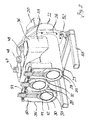
- the Fig. 2 shows a cross-sectional view of the circuit breaker housing 21 and the circuit breaker according to section line II-II (in Fig. 1 ).
- the switching chamber poles 11 and 12 Within the housing 21 are the switching chamber poles 11 and 12 and the in Fig. 1 non-visible switching chamber pole 28. These three switching chamber poles 11, 12 and 28 are arranged at the corners of an isosceles triangle whose plane spanned by the switching chamber poles 12, 28 is below and horizontally.
- the housing 21 is adapted to the switching chamber poles 11, 12 and 28. It therefore has one of the number of switching chamber poles 11, 12 and 28 corresponding number of chambers 29, 30 and 31, which are also associated with each other at the corners of the isosceles triangle on which the switching chamber poles 11, 12 and 28 are arranged.
- the chamber 29 for the switching chamber pole 11 encloses the switching chamber pole 11 such that the distance between the outer surface of the switching chamber pole 11 and the inner surface of the chamber 29 is dimensioned such that flashovers between the switching chamber pole 11 to the housing 21 are prevented.
- the chamber 29 is separated from the chamber 31 and 30 respectively by an intermediate wall 32, 33, so that the intermediate walls 32 and 33 each form part of the chamber 29 as well as a part of the chambers 30 and 31 and in a corresponding manner separate all chambers from each other ,
- the individual chambers 29, 30, 31 are approximately tubular, and in the region of the switching chamber poles 11, 12, 28 itself, a gas connection between the chambers 29, 30 and 31 is not given.
- the individual chambers 29, 30 and 31 are open towards their free ends and together with the respective chambers 29, 30, 31 covering lids 22, 23 completed.
- the interiors of the covers 22, 23 thus form the gas connection of the chambers 29, 30, 31 at the two ends of the housing 21st
- circuit breaker housing 21 between the front ends is formed by individual tubes, which are triangular, as shown in Fig. 3 clearly visible, are placed against each other, wherein in each case two tubes, the chamber 29 and 31 and 29 and 30 respectively via the two common partition walls 32, 33 are connected.
- the Fig. 1 shows the housing 21 to which perpendicular to the plane defined by the two switching chambers 30 and 31 plane three dome stubs 34, 35 and 36 are formed, of which in the Fig. 2 the Domstutzen 35 is shown in more detail.
- the dome stub 36 which is similar to the dome stub 34 and 35, is rectangular in cross-section, each two side walls 39 extend perpendicular to the longitudinal extension of the switching chambers 29, 30 and 31, whereas the side walls 39 extend approximately parallel to the longitudinal extent;
- the side walls 39 open approximately tangentially into the outer surfaces of the chambers 31 and 30 and are tapered together with the side walls 38, so that the cross-sectional area which is parallel to the plane passing through the switching chambers 31 and 30 plane, towards the free end of the Side walls 38 and 39 slightly tapered.
- the side walls 38 and 39 are connected at their free ends to an end wall 40, which closes the dome 36 and thus also the dome 34 and 35 at the top.
- openings 41, 42 and 43 In the end wall 40 are openings 41, 42 and 43, in which disc or Schott insulators 44, 45 and 46 are inserted gas-tight, which can be connected to connecting lines 47, 48, 49.
- the connecting lines 47, 48, 49 then lead in a manner not shown to a busbar arrangement.
- Domstutzens 34 is the same as that of the Domstutzens 36; the insulators and cable bushings used there are therefore not described in detail here.
- the dome sockets 34, 35 and 36 can each be closed with a cover cover 37 as a blanking cover.
- cover cover 37 As a blanking cover.
- the circuit breaker housing 21 is disposed lying horizontally together with the circuit breaker poles or switching chamber poles 11, 12 and 28 arranged therein and fastened by means of its flanges 26 and 27 via carrier 52 on a support frame 53.
- circuit breaker poles located at the corners of a triangle located at the corners of a triangle.
- a corresponding solution can also be provided if the individual circuit breaker poles lie in one plane, as in FIG Fig. 4 is shown. These can then be surrounded in the same way by a respective tube as in the arrangement according to the FIGS. 1 to 3 and also three dome sockets 34, 35 and 36 with disc or Schott insulators 34, 35 and 36 have, however, in the Fig. 4 are not shown.
Abstract
Description
- Die Erfindung betrifft einen elektrischen, gasisolierten Hochspannungsleistungsschalter gemäß dem Oberbegriff des Anspruches 1.
- Derartige Hochspannungsleistungsschalter besitzen eine der Anzahl der Phasen entsprechende Anzahl von Leistungsschalterpolen, die in einer Ebene nebeneinander oder an den Ecken eines Dreiecks angeordnet sind. Die einzelnen Pole können dabei in einer alle Pole aufnehmenden Kapselung oder jeweils für sich in einer eigenen Kapselung untergebracht sein. Üblicherweise sind überwiegend die mehrphasigen Leistungsschalterpole in einem kesselförmigen Gehäuse eingesetzt, welches senkrecht aufgestellt ist, wobei die Zu- und Abgangsleitungen quer dazu am Gehäuse angeschlossen sind.
- Bei einem derartigen kesselförmigen Gehäuse wird viel Raum benötigt und darüber hinaus auch eine große Menge an Isoliergas.
- Eine Schaltanlage dieser Art ist beispielsweise aus der Literaturstelle Schaltanlagenhandbund ABB, 11. Auflage, 2006, Seite 504, Bild 11-3 bekannt geworden. Die in dem Kessel angeordneten Leistungsschalterpole benötigen viel Raum und demgemäß ist die Menge des in der Metallkapselung eingebrachten Isoliergases sehr hoch.
- Aufgabe der Erfindung ist es, einen Leistungsschalter zu schaffen, bei dem einerseits Raum und Platz und andererseits auch Isoliergas eingespart wird.
- Diese Aufgabe wird erfindungsgemäß gelöst durch die Merkmale des Anspruches 1.
- Erfindungsgemäß besitzt das Leistungsschaltergehäuse eine der Anzahl der Pole entsprechende Anzahl von an ihren Stirnenden offenen Kammern, in denen die einzelnen Pole angeordnet sind. Die offenen Stirnenden der Kammern sind mittels je eines die Stirnenden überdeckenden domartigen Deckels verschlossen.
- Dadurch, dass die einzelnen Leistungsschalterpole in eigenen Kammern untergebracht sind, die lediglich an ihren Enden einen offenen Gasraum aufweisen, sodass die Gasverbindung zwischen den einzelnen Kammern jeweils an den Stirnenden erreicht wird, ist die Menge des verwendeten Isoliergases deutlich reduziert.
- Weitere vorteilhafte Ausgestaltungen und Verbesserungen der Erfindung sind den Unteransprüchen zu entnehmen.
- Anhand der Zeichnung, in der ein Ausführungsbeispiel der Erfindung dargestellt ist, sollen die Erfindung sowie weitere vorteilhafte Ausgestaltungen und Verbesserungen und weitere Vorteile näher erläutert und beschrieben werden.
- Es zeigen:
- Fig. 1
- eine Längsschnittansicht durch einen erfindungsgemäßen Leistungsschalter,
- Fig. 2
- eine Schnittansicht gemäß Schnittlinie II-II der
Fig. 1 - Fig. 3
- eine Schnittansicht gemäß der Schnittlinie III-III der
Fig. 1 , und - Fig. 4
- eine schematische Darstellung der Leistungsschalterpole in einer Ebene.
- Die
Fig. 1 zeigt eine Längsschnittansicht durch den erfindungsgemäßen Leistungsschalter 10, der eine der Anzahl der Phasen entsprechende Anzahl von Leistungsschalterpolen 11 und 12 besitzt, von denen der Leistungsschalterpol 11 in Schnittansicht schematisch dargestellt ist. Die Schaltkammer 13 ist ohne Einbauteile dargestellt. In der Die Schaltkammer 13 befindet sich ein festes Kontaktstück und ein bewegliches Kontaktstück, von denen das bewegliche Kontaktstück mit einer Schaltstange 14 verbunden ist, die aus dem Ende des Leistungsschalterpoles 11 herausragt, das der Schaltkammer 13 entgegengesetzt liegt. Die Schaltstange 14 ist mit einem Joch 15 verbunden, an dem die nicht gezeichneten Schaltstangen der anderen Leistungsschalterpole 12 und 28 zu angeschlossen sind; der dritte Leistungsschalterpol 28 liegt vor der Schnittebene und ist daher nicht sichtbar. Das Joch 15 besitzt dabei ein Zentralteil 16, an dem Arme 17 angeformt sind, an deren Enden die Schaltstangen 14 angeschlossen sind. Der Zentralteil 16 des Joches 15 ist mit einer Übertragungsstange 18 verbunden, die über eine Schubdurchführung 19 mit einem Antrieb 20 gekoppelt ist, der als hydraulischer Federspeicherantrieb ausgebildet und für die Erfindung nicht von Bedeutung ist, sodass er hier nicht näher beschrieben wird. In gleicher Weise ist auch die Schubdurchführung 19 für die Erfindung nicht von wesentlicher Bedeutung, sodass auch diese Schubdurchführung 19 nicht näher beschrieben wird. - Die Leistungsschalterpole 11 und 12, nachfolgend auch Schaltkammerpole genannt, sind in einem Leistungsschaltergehäuse 21, kurz auch Gehäuse 21 genannt, untergebracht, welches eine langgestreckte Form aufweist und an den freien, links und rechts befindlichen Enden mittels je eines domartigen Deckels 22 und 23 verschlossen ist. Im Deckel 22 befindet sich die Schubdurchführung 19. Die domartigen Deckel 22, 23 besitzen dabei Flansche 24, 25, die mit entsprechenden Flanschen 26 und 27 am Gehäuse 21 befestigt sind.
- An den Deckeln 22 und 23 können nicht näher dargestellte Durchführungen für Gasleitungen vorgesehen sein, an denen beispielsweise ein Dichtewächter oder dergleichen angeschlossen werden können.
- Der Deckel 22, der ebenso wie der Deckel 23 topfförmig ausgebildet ist, besitzt einen Stutzen 54 an dem eine Sicherheitseinheit 55, beispielsweise eine Berstscheibe, angeflanscht werden kann. Die Sicherheitseinheit 55 schützt das Gehäuse 21 des Hochspannungsleistungsschalters bei einem Störfall vor Beschädigungen.
- Es sei nun Bezug genommen auf die
Fig. 2 . - Die
Fig. 2 zeigt eine Querschnittansicht des Leistungsschaltergehäuses 21 beziehungsweise den Leistungsschalter gemäß Schnittlinie II-II (inFig. 1 ). Innerhalb des Gehäuses 21 befinden sich die Schaltkammerpole 11 und 12 sowie den inFig. 1 nicht sichtbare Schaltkammerpol 28. Diese drei Schaltkammerpole 11, 12 und 28 sind an den Ecken eines gleichschenkligen Dreiecks angeordnet, dessen durch die Schaltkammerpole 12, 28 aufgespannte Ebene unten und horizontal liegt. - Das Gehäuse 21 ist den Schaltkammerpolen 11, 12 und 28 angepasst. Es besitzt daher eine der Anzahl der Schaltkammerpole 11, 12 und 28 entsprechende Anzahl von Kammern 29, 30 und 31, die ebenfalls an den Ecken des gleichschenkligen Dreiecks, auf dem die Schaltkammerpole 11, 12 und 28 angeordnet sind, einander zugeordnet sind. Die Kammer 29 für den Schaltkammerpol 11 umschließt den Schaltkammerpol 11 derart, dass der Abstand der Außenfläche des Schaltkammerpoles 11 und der Innenfläche der Kammer 29 so bemessen ist, dass Überschläge zwischen dem Schaltkammerpol 11 zu dem Gehäuse 21 verhindert sind. Die Kammer 29 ist von der Kammer 31 und 30 jeweils durch eine Zwischenwand 32, 33 getrennt, sodass die Zwischenwände 32 und 33 sowohl je einen Teil der Kammer 29 als auch einen Teil der Kammern 30 beziehungsweise 31 bilden und in entsprechender Weise alle Kammern voneinander trennen. Die einzelnen Kammern 29, 30, 31 sind etwa rohrförmig ausgebildet, und im Bereich der Schaltkammerpole 11, 12, 28 selbst ist eine Gasverbindung zwischen den Kammern 29, 30 und 31 nicht gegeben.
- Die einzelnen Kammern 29, 30 und 31 sind zu ihren freien Enden hin offen und gemeinsam jeweils mit den Kammern 29, 30, 31 abdeckenden Deckeln 22, 23 abgeschlossen. Die Innenräume der Deckel 22, 23 bilden somit die Gasverbindung der Kammern 29, 30, 31 an den beiden Enden des Gehäuses 21.
- Dadurch, dass die einzelnen Kammern 29, 30 und 31 wie Einzelkapselungen wirken, was insbesondere aus der
Fig. 3 deutlich ersichtlich ist, wird einerseits der Platzbedarf reduziert und andererseits die Menge des innerhalb des Gehäuses 21 befindlichen Isoliergases gegenüber einer sogenannten Kessellösung deutlich verringert. - Mit anderen Worten: das Leistungsschaltergehäuse 21 zwischen den Stirnenden wird durch einzelne Rohre gebildet, die dreieckförmig, wie aus der
Fig. 3 deutlich ersichtlich ist, aneinander gelegt sind, wobei jeweils zwei Rohre, die Kammer 29 und 31 beziehungsweise 29 und 30 jeweils über die beiden gemeinsamen Zwischenwände 32, 33 verbunden sind. - Die
Fig. 1 zeigt das Gehäuse 21, an dem senkrecht zu der durch die beiden Schaltkammern 30 und 31 aufgespannten Ebene drei Domstutzen 34, 35 und 36 angeformt sind, von denen in derFig. 2 der Domstutzen 35 näher dargestellt ist. - Es sei nun die
Fig. 3 betrachtet. - Der Domstutzen 36, der den Domstutzen 34 und 35 gleicht, ist rechteckförmig im Querschnitt, wobei je zwei Seitenwände 39 senkrecht zur Längserstreckung der Schaltkammern 29, 30 und 31 verlaufen, wogegen die Seitenwände 39 etwa parallel zu der Längserstreckung verlaufen; die Seitenwände 39 münden etwa tangential in die Außenflächen der Kammern 31 und 30 ein und sind zusammen mit den Seitenwänden 38 sich verjüngend ausgerichtet, sodass sich die Querschnittsfläche, die parallel zu der durch die Schaltkammern 31 und 30 verlaufenden Ebene verläuft, hin zum freien Ende der Seitenwände 38 und 39 leicht verjüngt. Die Seitenwände 38 und 39 sind an ihren freien Enden mit einer Abschlusswand 40 verbunden, die den Dom 36 und damit auch die Dome 34 und 35 nach oben hin abschließt. In der Abschlusswand 40 befinden sich Öffnungen 41, 42 und 43, in denen Scheiben- oder Schottisolatoren 44, 45 und 46 gasdicht eingesetzt sind, die mit Anschlussleitungen 47, 48, 49 verbunden werden können. Die Anschlussleitungen 47, 48, 49 führen dann in nicht näher dargestellter Weise zu einer Sammelschienenanordnung.
- Die Ausführung des Domstutzens 34 ist die Gleiche wie die des Domstutzens 36; die dort eingesetzten Isolatoren und Leitungsdurchführungen sind deshalb hier nicht näher beschrieben.
- Die Domstutzen 34, 35 und 36 können jeweils mit einem Abschlussdeckel 37 als Blindabdeckung verschlossen werden. In der
Fig. 2 sind die den Seitenwänden 39 entsprechenden Seitenwände 50 und 51 von innen zu sehen, wobei diese Seitenwände in derFig. 3 nicht sichtbar sind. - Das Leistungsschaltergehäuse 21 ist zusammen mit den darin angeordneten Leistungsschalterpolen oder Schaltkammerpolen 11, 12 und 28 liegend angeordnet und mittels seiner Flansche 26 und 27 über Träger 52 auf einem Tragegestell 53 befestigt.
- Die Anmeldung ist beschrieben für Leistungsschalterpole, die an den Ecken eines Dreiecks angeordnet sind. Eine entsprechende Lösung kann aber auch dann vorgesehen sein, wenn die einzelnen Leistungsschalterpole in einer Ebene liegen, wie in
Fig. 4 dargestellt ist. Diese können dann in gleicher Weise von jeweils einem Rohr so umgeben sein wie bei der Anordnung gemäß denFiguren 1 bis 3 und ebenso drei Domstutzen 34, 35 und 36 mit Scheiben- oder Schottisolatoren 34, 35 und 36 aufweisen, die jedoch in derFig. 4 nicht dargestellt sind. -
- 10
- Leistungsschalter
- 11
- Leistungsschalterpol
- 12
- Leistungsschalterpol
- 13
- Schaltkammer
- 14
- Schaltstange
- 15
- Joch
- 16
- Zentralteil
- 17
- Arm
- 18
- Übertragungsstange
- 19
- Schubdurchführung
- 20
- Antrieb
- 21
- Leistungsschaltergehäuse, Gehäuse
- 22
- Deckel
- 23
- Deckel
- 24
- Flansch
- 25
- Flansch
- 26
- Flansch
- 27
- Flansch
- 28
- Leistungsschalterpol
- 29
- Kammer
- 30
- Kammer
- 31
- Kammer
- 32
- Zwischenwand
- 33
- Zwischenwand
- 34
- Domstutzen
- 35
- Domstutzen
- 36
- Domstutzen
- 37
- Abschlussdeckel
- 38
- Seitenwand
- 39
- Seitenwand
- 40
- Abschlusswand
- 41
- Öffnung
- 42
- Öffnung
- 43
- Öffnung
- 44
- Schottisolator
- 45
- Schottisolator
- 46
- Schottisolator
- 47
- Anschlussleitung
- 48
- Anschlussleitung
- 49
- Anschlussleitung
- 50
- Seitenwand
- 51
- Seitenwand
- 52
- Träger
- 53
- Gestell
- 55
- Sicherheitseinheit
Claims (9)
- Mehrphasiger, insbesondere dreiphasiger, metallgekapselter, gasisolierter Hochspannungsleistungsschalter, mit je einem Leistungsschalterpol (11), (12), (28) pro Phase, die miteinander in einem gemeinsamen Leistungsschaltergehäuse (21) untergebracht sind, und mit wenigstens zwei Anschlussabgängen pro Phase, dadurch gekennzeichnet, dass das Leistungsschaltergehäuse (21) eine der Anzahl der Pole (11), (12), (28) entsprechende Anzahl von an ihren Stirnenden offenen Kammern (29), (30), (31) aufweist, in denen die Pole (11), (12), (28) angeordnet sind, und dass die offenen Stirnenden der Kammer (29), (30), (31) mittels je eines die Stirnenden überdeckenden domartigen Deckels (22), (23) verschlossen sind, so dass die Gasverbindung zwischen den einzelnen Kammern (29), (30), (31) über die durch die Deckel (22), (23) erzeugten Verbindungsräume ermöglicht ist.
- Leistungsschalter nach Anspruch 1, dadurch gekennzeichnet, dass die Kammern (29), (30), (31) durch Rohre gebildet sind, in denen die Pole (11), (12), (28) angeordnet sind, wobei der Abstand des Außendurchmessers der Pole (11), (12), (28) vom Innendurchmesser der Rohre durch die Isolierfähigkeit des Gases bestimmt ist.
- Leistungsschalter, nach einem der vorherigen Ansprüche, dadurch gekennzeichnet, dass die Leistungsschalterpole (11), (12), (28) bildenden Rohre ebenfalls dreieckförmig einander zugeordnet sind.
- Leistungsschalter, nach einem der Ansprüche 1 oder 2, dadurch gekennzeichnet, dass die Leistungsschalterpole (11), (12), (28) in einer Ebene angeordnet sind.
- Leistungsschalter nach einem der vorherigen Ansprüche, dadurch gekennzeichnet, dass die einzelnen die Kammer (29), (30), (31) bildenden Rohre von den jeweils benachbarten mittels einer gemeinsamen Trennwand getrennt sind.
- Leistungsschalter nach Anspruch 5, dadurch gekennzeichnet, dass die Trennwände zwischen den Kammern (29), (30), (31) jeweils Teile der Rohre bilden.
- Leistungsschalter nach einem der vorherigen Ansprüche, dadurch gekennzeichnet, dass das Leistungsschaltergehäuse (21) Domstutzen (34), (35) und (36) aufweist, die senkrecht zur Längserstreckung vom Gehäuse (21) aus vorspringen beziehungsweise an diesen angeformt sind, wobei an den freien Abschlusswänden (40) Öffnungen (41), (42), (43) vorgesehen sind, in die Schottungsisolatoren einsetzbar sind.
- Leistungsschalter nach Anspruch 5, dadurch gekennzeichnet, dass insgesamt drei Domstutzen (34), (35), (36) vorgesehen sind, von denen der eine Domstutzen die zu den Leistungsschalterpolen (11), (12), (28) führenden Zuleitungen und die beiden anderen zu einer ersten oder einer zweiten Sammelschiene führen, wobei der keine Anschlussleitungen aufweisende Domstutzen mit einer Blindplatte verschließbar oder verschlossen ist.
- Leistungsschalter nach einem der vorherigen Ansprüche, dadurch gekennzeichnet, dass der der eigentlichen Schaltkammer (29), (30), (31) der Leistungsschalterpole (11), (12), (28) entgegengesetzt liegende Deckel (22), (23) eine Schubdurchführung (19) für einen Antrieb (20) der Leistungsschalterpole aufweist.
Applications Claiming Priority (1)
| Application Number | Priority Date | Filing Date | Title |
|---|---|---|---|
| DE102009022106 | 2009-05-20 |
Publications (2)
| Publication Number | Publication Date |
|---|---|
| EP2273525A1 true EP2273525A1 (de) | 2011-01-12 |
| EP2273525B1 EP2273525B1 (de) | 2016-06-15 |
Family
ID=42546392
Family Applications (1)
| Application Number | Title | Priority Date | Filing Date |
|---|---|---|---|
| EP09011746.6A Active EP2273525B1 (de) | 2009-05-20 | 2009-09-15 | Elektrischer Leistungsschalter |
Country Status (4)
| Country | Link |
|---|---|
| EP (1) | EP2273525B1 (de) |
| CN (1) | CN201594712U (de) |
| HU (1) | HUE030600T2 (de) |
| UA (1) | UA103384C2 (de) |
Cited By (1)
| Publication number | Priority date | Publication date | Assignee | Title |
|---|---|---|---|---|
| WO2018015104A1 (de) * | 2016-07-19 | 2018-01-25 | Siemens Aktiengesellschaft | Schaltgeräteanordnung |
Citations (2)
| Publication number | Priority date | Publication date | Assignee | Title |
|---|---|---|---|---|
| DE695051C (de) * | 1934-03-21 | 1940-08-15 | Siemens Schuckertwerke Akt Ges | Mehrpoliger Schalter mit Lichtbogenloeschung durch stroemende oder expandierende Gase oder Daempfe |
| US3641295A (en) | 1969-07-07 | 1972-02-08 | Merlin Gerin | Polyphase circuit interrupter of the fluid blast puffer-type |
-
2009
- 2009-09-15 EP EP09011746.6A patent/EP2273525B1/de active Active
- 2009-09-15 HU HUE09011746A patent/HUE030600T2/hu unknown
- 2009-09-25 CN CN2009201780236U patent/CN201594712U/zh not_active Expired - Lifetime
-
2010
- 2010-05-10 UA UAA201113619A patent/UA103384C2/ru unknown
Patent Citations (2)
| Publication number | Priority date | Publication date | Assignee | Title |
|---|---|---|---|---|
| DE695051C (de) * | 1934-03-21 | 1940-08-15 | Siemens Schuckertwerke Akt Ges | Mehrpoliger Schalter mit Lichtbogenloeschung durch stroemende oder expandierende Gase oder Daempfe |
| US3641295A (en) | 1969-07-07 | 1972-02-08 | Merlin Gerin | Polyphase circuit interrupter of the fluid blast puffer-type |
Cited By (2)
| Publication number | Priority date | Publication date | Assignee | Title |
|---|---|---|---|---|
| WO2018015104A1 (de) * | 2016-07-19 | 2018-01-25 | Siemens Aktiengesellschaft | Schaltgeräteanordnung |
| US10650994B2 (en) | 2016-07-19 | 2020-05-12 | Siemens Aktiengesellschaft | Switching device arrangement |
Also Published As
| Publication number | Publication date |
|---|---|
| HUE030600T2 (hu) | 2017-05-29 |
| EP2273525B1 (de) | 2016-06-15 |
| UA103384C2 (ru) | 2013-10-10 |
| CN201594712U (zh) | 2010-09-29 |
Similar Documents
| Publication | Publication Date | Title |
|---|---|---|
| DE3715053C2 (de) | ||
| DE102010013877B4 (de) | Elektrischer Leistungsschalter und Schaltfeld mit Leistungsschalter | |
| DE2754691C2 (de) | Ein- oder mehrphasig metallgekapselte, druckgasisolierte Hochspannungsschaltanlage | |
| EP0688071B2 (de) | Metallgekapselte gasisolierte Schaltanlage | |
| WO2005083859A1 (de) | Gekapselte gasisolierte schaltanlage | |
| DE2924430A1 (de) | Metallgekapselte, sf tief 6 -gasisolierte schaltanlage | |
| EP1851839B1 (de) | Schaltanlage | |
| EP2254135B1 (de) | Metallgekapselter, mehrphasiger, gasisolierter Sammelschienentrenn- und Erdungsschalter | |
| EP1249910B1 (de) | Hochspannungs-Leistungsschalter für eine druckgasisolierte Schaltanlage | |
| EP2104969B1 (de) | Hochspannungsschaltanlage | |
| EP0205397B1 (de) | Trennschalter für eine metallgekapselte, druckgasisolierte Hochspannungsschaltanlage | |
| DE3331222C2 (de) | ||
| DE102006001237A1 (de) | Gasisolierte, dreiphasige gekapselte Schaltanlage | |
| DE2823056C2 (de) | ||
| DE102010026014A1 (de) | Druckgasisoliertes mehrphasiges Schaltfeld | |
| EP2273525B1 (de) | Elektrischer Leistungsschalter | |
| EP0796502B1 (de) | Metallgekapselte schaltanlage mit einem vakuumschaltgerät | |
| DE19641391C1 (de) | Hochspannungsschaltanlage in Hybridbauweise | |
| DE19606213A1 (de) | Schaltfeld in einer elektrischen, metallgekapselten, gasisolierten Hochspannungsschaltanlage | |
| EP1683246B1 (de) | Mittelspannungsschaltanlage | |
| EP3276647B1 (de) | Erdungseinheit für eine schaltanlage | |
| DE102010004971A1 (de) | Vorrichtung für eine Schaltanlage | |
| DE2856187A1 (de) | Mehrpolige umschalteinrichtung | |
| EP3164919A1 (de) | Kabelendverschluss zur anbindung einer schaltanlage an ein hochspannungskabel | |
| WO2011054933A1 (de) | Ein- oder zweipolige elektrische schaltanlage, insbesondere mittelspannungsschaltanlage |
Legal Events
| Date | Code | Title | Description |
|---|---|---|---|
| PUAI | Public reference made under article 153(3) epc to a published international application that has entered the european phase |
Free format text: ORIGINAL CODE: 0009012 |
|
| 17P | Request for examination filed |
Effective date: 20100909 |
|
| AK | Designated contracting states |
Kind code of ref document: A1 Designated state(s): AT BE BG CH CY CZ DE DK EE ES FI FR GB GR HR HU IE IS IT LI LT LU LV MC MK MT NL NO PL PT RO SE SI SK SM TR |
|
| AX | Request for extension of the european patent |
Extension state: AL BA RS |
|
| GRAP | Despatch of communication of intention to grant a patent |
Free format text: ORIGINAL CODE: EPIDOSNIGR1 |
|
| RIC1 | Information provided on ipc code assigned before grant |
Ipc: H01H 33/56 20060101ALI20160209BHEP Ipc: H01H 33/02 20060101AFI20160209BHEP Ipc: H02B 13/045 20060101ALI20160209BHEP |
|
| INTG | Intention to grant announced |
Effective date: 20160304 |
|
| GRAS | Grant fee paid |
Free format text: ORIGINAL CODE: EPIDOSNIGR3 |
|
| GRAA | (expected) grant |
Free format text: ORIGINAL CODE: 0009210 |
|
| AK | Designated contracting states |
Kind code of ref document: B1 Designated state(s): AT BE BG CH CY CZ DE DK EE ES FI FR GB GR HR HU IE IS IT LI LT LU LV MC MK MT NL NO PL PT RO SE SI SK SM TR |
|
| REG | Reference to a national code |
Ref country code: CH Ref legal event code: EP Ref country code: GB Ref legal event code: FG4D Free format text: NOT ENGLISH |
|
| REG | Reference to a national code |
Ref country code: IE Ref legal event code: FG4D Free format text: LANGUAGE OF EP DOCUMENT: GERMAN |
|
| REG | Reference to a national code |
Ref country code: AT Ref legal event code: REF Ref document number: 806860 Country of ref document: AT Kind code of ref document: T Effective date: 20160715 |
|
| REG | Reference to a national code |
Ref country code: DE Ref legal event code: R096 Ref document number: 502009012695 Country of ref document: DE |
|
| REG | Reference to a national code |
Ref country code: CH Ref legal event code: NV Representative=s name: ABB SCHWEIZ AG INTELLECTUAL PROPERTY (CH-LC/IP, CH |
|
| REG | Reference to a national code |
Ref country code: FR Ref legal event code: PLFP Year of fee payment: 8 |
|
| REG | Reference to a national code |
Ref country code: LT Ref legal event code: MG4D |
|
| REG | Reference to a national code |
Ref country code: NL Ref legal event code: MP Effective date: 20160615 |
|
| PG25 | Lapsed in a contracting state [announced via postgrant information from national office to epo] |
Ref country code: NO Free format text: LAPSE BECAUSE OF FAILURE TO SUBMIT A TRANSLATION OF THE DESCRIPTION OR TO PAY THE FEE WITHIN THE PRESCRIBED TIME-LIMIT Effective date: 20160915 Ref country code: FI Free format text: LAPSE BECAUSE OF FAILURE TO SUBMIT A TRANSLATION OF THE DESCRIPTION OR TO PAY THE FEE WITHIN THE PRESCRIBED TIME-LIMIT Effective date: 20160615 Ref country code: LT Free format text: LAPSE BECAUSE OF FAILURE TO SUBMIT A TRANSLATION OF THE DESCRIPTION OR TO PAY THE FEE WITHIN THE PRESCRIBED TIME-LIMIT Effective date: 20160615 |
|
| PG25 | Lapsed in a contracting state [announced via postgrant information from national office to epo] |
Ref country code: NL Free format text: LAPSE BECAUSE OF FAILURE TO SUBMIT A TRANSLATION OF THE DESCRIPTION OR TO PAY THE FEE WITHIN THE PRESCRIBED TIME-LIMIT Effective date: 20160615 Ref country code: LV Free format text: LAPSE BECAUSE OF FAILURE TO SUBMIT A TRANSLATION OF THE DESCRIPTION OR TO PAY THE FEE WITHIN THE PRESCRIBED TIME-LIMIT Effective date: 20160615 Ref country code: GR Free format text: LAPSE BECAUSE OF FAILURE TO SUBMIT A TRANSLATION OF THE DESCRIPTION OR TO PAY THE FEE WITHIN THE PRESCRIBED TIME-LIMIT Effective date: 20160916 Ref country code: SE Free format text: LAPSE BECAUSE OF FAILURE TO SUBMIT A TRANSLATION OF THE DESCRIPTION OR TO PAY THE FEE WITHIN THE PRESCRIBED TIME-LIMIT Effective date: 20160615 Ref country code: HR Free format text: LAPSE BECAUSE OF FAILURE TO SUBMIT A TRANSLATION OF THE DESCRIPTION OR TO PAY THE FEE WITHIN THE PRESCRIBED TIME-LIMIT Effective date: 20160615 |
|
| PG25 | Lapsed in a contracting state [announced via postgrant information from national office to epo] |
Ref country code: IT Free format text: LAPSE BECAUSE OF FAILURE TO SUBMIT A TRANSLATION OF THE DESCRIPTION OR TO PAY THE FEE WITHIN THE PRESCRIBED TIME-LIMIT Effective date: 20160615 Ref country code: RO Free format text: LAPSE BECAUSE OF FAILURE TO SUBMIT A TRANSLATION OF THE DESCRIPTION OR TO PAY THE FEE WITHIN THE PRESCRIBED TIME-LIMIT Effective date: 20160615 Ref country code: SK Free format text: LAPSE BECAUSE OF FAILURE TO SUBMIT A TRANSLATION OF THE DESCRIPTION OR TO PAY THE FEE WITHIN THE PRESCRIBED TIME-LIMIT Effective date: 20160615 Ref country code: EE Free format text: LAPSE BECAUSE OF FAILURE TO SUBMIT A TRANSLATION OF THE DESCRIPTION OR TO PAY THE FEE WITHIN THE PRESCRIBED TIME-LIMIT Effective date: 20160615 Ref country code: IS Free format text: LAPSE BECAUSE OF FAILURE TO SUBMIT A TRANSLATION OF THE DESCRIPTION OR TO PAY THE FEE WITHIN THE PRESCRIBED TIME-LIMIT Effective date: 20161015 Ref country code: CZ Free format text: LAPSE BECAUSE OF FAILURE TO SUBMIT A TRANSLATION OF THE DESCRIPTION OR TO PAY THE FEE WITHIN THE PRESCRIBED TIME-LIMIT Effective date: 20160615 |
|
| PG25 | Lapsed in a contracting state [announced via postgrant information from national office to epo] |
Ref country code: PL Free format text: LAPSE BECAUSE OF FAILURE TO SUBMIT A TRANSLATION OF THE DESCRIPTION OR TO PAY THE FEE WITHIN THE PRESCRIBED TIME-LIMIT Effective date: 20160615 Ref country code: BE Free format text: LAPSE BECAUSE OF NON-PAYMENT OF DUE FEES Effective date: 20160930 Ref country code: SM Free format text: LAPSE BECAUSE OF FAILURE TO SUBMIT A TRANSLATION OF THE DESCRIPTION OR TO PAY THE FEE WITHIN THE PRESCRIBED TIME-LIMIT Effective date: 20160615 Ref country code: PT Free format text: LAPSE BECAUSE OF FAILURE TO SUBMIT A TRANSLATION OF THE DESCRIPTION OR TO PAY THE FEE WITHIN THE PRESCRIBED TIME-LIMIT Effective date: 20161017 Ref country code: ES Free format text: LAPSE BECAUSE OF FAILURE TO SUBMIT A TRANSLATION OF THE DESCRIPTION OR TO PAY THE FEE WITHIN THE PRESCRIBED TIME-LIMIT Effective date: 20160615 |
|
| REG | Reference to a national code |
Ref country code: DE Ref legal event code: R097 Ref document number: 502009012695 Country of ref document: DE |
|
| REG | Reference to a national code |
Ref country code: DE Ref legal event code: R081 Ref document number: 502009012695 Country of ref document: DE Owner name: HITACHI ENERGY SWITZERLAND AG, CH Free format text: FORMER OWNER: ABB TECHNOLOGY AG, ZUERICH, CH Ref country code: DE Ref legal event code: R081 Ref document number: 502009012695 Country of ref document: DE Owner name: ABB SCHWEIZ AG, CH Free format text: FORMER OWNER: ABB TECHNOLOGY AG, ZUERICH, CH Ref country code: DE Ref legal event code: R081 Ref document number: 502009012695 Country of ref document: DE Owner name: ABB POWER GRIDS SWITZERLAND AG, CH Free format text: FORMER OWNER: ABB TECHNOLOGY AG, ZUERICH, CH Ref country code: DE Ref legal event code: R082 Ref document number: 502009012695 Country of ref document: DE Representative=s name: DENNEMEYER & ASSOCIATES S.A., DE Ref country code: DE Ref legal event code: R082 Ref document number: 502009012695 Country of ref document: DE Representative=s name: ZIMMERMANN & PARTNER PATENTANWAELTE MBB, DE |
|
| PLBE | No opposition filed within time limit |
Free format text: ORIGINAL CODE: 0009261 |
|
| STAA | Information on the status of an ep patent application or granted ep patent |
Free format text: STATUS: NO OPPOSITION FILED WITHIN TIME LIMIT |
|
| PG25 | Lapsed in a contracting state [announced via postgrant information from national office to epo] |
Ref country code: MC Free format text: LAPSE BECAUSE OF FAILURE TO SUBMIT A TRANSLATION OF THE DESCRIPTION OR TO PAY THE FEE WITHIN THE PRESCRIBED TIME-LIMIT Effective date: 20160615 |
|
| RAP2 | Party data changed (patent owner data changed or rights of a patent transferred) |
Owner name: ABB SCHWEIZ AG |
|
| 26N | No opposition filed |
Effective date: 20170316 |
|
| GBPC | Gb: european patent ceased through non-payment of renewal fee |
Effective date: 20160915 |
|
| REG | Reference to a national code |
Ref country code: HU Ref legal event code: AG4A Ref document number: E030600 Country of ref document: HU |
|
| PG25 | Lapsed in a contracting state [announced via postgrant information from national office to epo] |
Ref country code: DK Free format text: LAPSE BECAUSE OF FAILURE TO SUBMIT A TRANSLATION OF THE DESCRIPTION OR TO PAY THE FEE WITHIN THE PRESCRIBED TIME-LIMIT Effective date: 20160615 |
|
| REG | Reference to a national code |
Ref country code: IE Ref legal event code: MM4A |
|
| PG25 | Lapsed in a contracting state [announced via postgrant information from national office to epo] |
Ref country code: GB Free format text: LAPSE BECAUSE OF NON-PAYMENT OF DUE FEES Effective date: 20160915 Ref country code: IE Free format text: LAPSE BECAUSE OF NON-PAYMENT OF DUE FEES Effective date: 20160915 |
|
| PG25 | Lapsed in a contracting state [announced via postgrant information from national office to epo] |
Ref country code: LU Free format text: LAPSE BECAUSE OF NON-PAYMENT OF DUE FEES Effective date: 20160915 Ref country code: SI Free format text: LAPSE BECAUSE OF FAILURE TO SUBMIT A TRANSLATION OF THE DESCRIPTION OR TO PAY THE FEE WITHIN THE PRESCRIBED TIME-LIMIT Effective date: 20160615 |
|
| REG | Reference to a national code |
Ref country code: FR Ref legal event code: PLFP Year of fee payment: 9 |
|
| REG | Reference to a national code |
Ref country code: AT Ref legal event code: MM01 Ref document number: 806860 Country of ref document: AT Kind code of ref document: T Effective date: 20160915 |
|
| REG | Reference to a national code |
Ref country code: BE Ref legal event code: MM Effective date: 20160930 |
|
| REG | Reference to a national code |
Ref country code: HU Ref legal event code: GB9C Owner name: ABB SCHWEIZ AG, CH Free format text: FORMER OWNER(S): ABB TECHNOLOGY AG, CH |
|
| PG25 | Lapsed in a contracting state [announced via postgrant information from national office to epo] |
Ref country code: AT Free format text: LAPSE BECAUSE OF NON-PAYMENT OF DUE FEES Effective date: 20160915 |
|
| REG | Reference to a national code |
Ref country code: CH Ref legal event code: PFUS Owner name: ABB SCHWEIZ AG, CH Free format text: FORMER OWNER: ABB TECHNOLOGY AG, CH |
|
| PG25 | Lapsed in a contracting state [announced via postgrant information from national office to epo] |
Ref country code: CY Free format text: LAPSE BECAUSE OF FAILURE TO SUBMIT A TRANSLATION OF THE DESCRIPTION OR TO PAY THE FEE WITHIN THE PRESCRIBED TIME-LIMIT Effective date: 20160615 |
|
| PG25 | Lapsed in a contracting state [announced via postgrant information from national office to epo] |
Ref country code: MT Free format text: LAPSE BECAUSE OF FAILURE TO SUBMIT A TRANSLATION OF THE DESCRIPTION OR TO PAY THE FEE WITHIN THE PRESCRIBED TIME-LIMIT Effective date: 20160615 Ref country code: MK Free format text: LAPSE BECAUSE OF FAILURE TO SUBMIT A TRANSLATION OF THE DESCRIPTION OR TO PAY THE FEE WITHIN THE PRESCRIBED TIME-LIMIT Effective date: 20160615 Ref country code: TR Free format text: LAPSE BECAUSE OF FAILURE TO SUBMIT A TRANSLATION OF THE DESCRIPTION OR TO PAY THE FEE WITHIN THE PRESCRIBED TIME-LIMIT Effective date: 20160615 |
|
| PG25 | Lapsed in a contracting state [announced via postgrant information from national office to epo] |
Ref country code: BG Free format text: LAPSE BECAUSE OF FAILURE TO SUBMIT A TRANSLATION OF THE DESCRIPTION OR TO PAY THE FEE WITHIN THE PRESCRIBED TIME-LIMIT Effective date: 20160615 |
|
| REG | Reference to a national code |
Ref country code: FR Ref legal event code: PLFP Year of fee payment: 10 |
|
| REG | Reference to a national code |
Ref country code: CH Ref legal event code: PUE Owner name: ABB POWER GRIDS SWITZERLAND AG, CH Free format text: FORMER OWNER: ABB SCHWEIZ AG, CH |
|
| REG | Reference to a national code |
Ref country code: DE Ref legal event code: R081 Ref document number: 502009012695 Country of ref document: DE Owner name: HITACHI ENERGY SWITZERLAND AG, CH Free format text: FORMER OWNER: ABB SCHWEIZ AG, BADEN, CH Ref country code: DE Ref legal event code: R081 Ref document number: 502009012695 Country of ref document: DE Owner name: HITACHI ENERGY LTD, CH Free format text: FORMER OWNER: ABB SCHWEIZ AG, BADEN, CH Ref country code: DE Ref legal event code: R082 Ref document number: 502009012695 Country of ref document: DE Representative=s name: DENNEMEYER & ASSOCIATES S.A., DE Ref country code: DE Ref legal event code: R081 Ref document number: 502009012695 Country of ref document: DE Owner name: ABB POWER GRIDS SWITZERLAND AG, CH Free format text: FORMER OWNER: ABB SCHWEIZ AG, BADEN, CH |
|
| REG | Reference to a national code |
Ref country code: DE Ref legal event code: R081 Ref document number: 502009012695 Country of ref document: DE Owner name: HITACHI ENERGY SWITZERLAND AG, CH Free format text: FORMER OWNER: ABB POWER GRIDS SWITZERLAND AG, BADEN, CH Ref country code: DE Ref legal event code: R081 Ref document number: 502009012695 Country of ref document: DE Owner name: HITACHI ENERGY LTD, CH Free format text: FORMER OWNER: ABB POWER GRIDS SWITZERLAND AG, BADEN, CH |
|
| REG | Reference to a national code |
Ref country code: HU Ref legal event code: HC9C Owner name: HITACHI ENERGY SWITZERLAND AG, CH Free format text: FORMER OWNER(S): ABB TECHNOLOGY AG, CH; ABB POWER GRIDS SWITZERLAND AG, CH; ABB SCHWEIZ AG, CH Ref country code: HU Ref legal event code: GB9C Owner name: HITACHI ENERGY SWITZERLAND AG, CH Free format text: FORMER OWNER(S): ABB TECHNOLOGY AG, CH; ABB POWER GRIDS SWITZERLAND AG, CH; ABB SCHWEIZ AG, CH |
|
| P01 | Opt-out of the competence of the unified patent court (upc) registered |
Effective date: 20230527 |
|
| PGFP | Annual fee paid to national office [announced via postgrant information from national office to epo] |
Ref country code: HU Payment date: 20230922 Year of fee payment: 15 Ref country code: FR Payment date: 20230928 Year of fee payment: 15 Ref country code: DE Payment date: 20230920 Year of fee payment: 15 |
|
| PGFP | Annual fee paid to national office [announced via postgrant information from national office to epo] |
Ref country code: CH Payment date: 20231001 Year of fee payment: 15 |
|
| REG | Reference to a national code |
Ref country code: DE Ref legal event code: R082 Ref document number: 502009012695 Country of ref document: DE Representative=s name: DENNEMEYER & ASSOCIATES S.A., DE Ref country code: DE Ref legal event code: R081 Ref document number: 502009012695 Country of ref document: DE Owner name: HITACHI ENERGY LTD, CH Free format text: FORMER OWNER: HITACHI ENERGY SWITZERLAND AG, BADEN, CH |
|
| REG | Reference to a national code |
Ref country code: HU Ref legal event code: GB9C Owner name: HITACHI ENERGY LTD, CH Free format text: FORMER OWNER(S): ABB TECHNOLOGY AG, CH; ABB POWER GRIDS SWITZERLAND AG, CH; ABB SCHWEIZ AG, CH; HITACHI ENERGY SWITZERLAND AG, CH Ref country code: HU Ref legal event code: FH1C Free format text: FORMER REPRESENTATIVE(S): SBGK SZABADALMI UEGYVIVOEI IRODA, HU Representative=s name: SBGK SZABADALMI UEGYVIVOEI IRODA, HU |