EP2273311A1 - A safety interlock system for a projector system - Google Patents
A safety interlock system for a projector system Download PDFInfo
- Publication number
- EP2273311A1 EP2273311A1 EP10182202A EP10182202A EP2273311A1 EP 2273311 A1 EP2273311 A1 EP 2273311A1 EP 10182202 A EP10182202 A EP 10182202A EP 10182202 A EP10182202 A EP 10182202A EP 2273311 A1 EP2273311 A1 EP 2273311A1
- Authority
- EP
- European Patent Office
- Prior art keywords
- lamp
- ballast
- projector
- module
- power
- Prior art date
- Legal status (The legal status is an assumption and is not a legal conclusion. Google has not performed a legal analysis and makes no representation as to the accuracy of the status listed.)
- Withdrawn
Links
Images


Classifications
-
- G—PHYSICS
- G03—PHOTOGRAPHY; CINEMATOGRAPHY; ANALOGOUS TECHNIQUES USING WAVES OTHER THAN OPTICAL WAVES; ELECTROGRAPHY; HOLOGRAPHY
- G03B—APPARATUS OR ARRANGEMENTS FOR TAKING PHOTOGRAPHS OR FOR PROJECTING OR VIEWING THEM; APPARATUS OR ARRANGEMENTS EMPLOYING ANALOGOUS TECHNIQUES USING WAVES OTHER THAN OPTICAL WAVES; ACCESSORIES THEREFOR
- G03B21/00—Projectors or projection-type viewers; Accessories therefor
- G03B21/14—Details
- G03B21/20—Lamp housings
-
- H—ELECTRICITY
- H05—ELECTRIC TECHNIQUES NOT OTHERWISE PROVIDED FOR
- H05B—ELECTRIC HEATING; ELECTRIC LIGHT SOURCES NOT OTHERWISE PROVIDED FOR; CIRCUIT ARRANGEMENTS FOR ELECTRIC LIGHT SOURCES, IN GENERAL
- H05B47/00—Circuit arrangements for operating light sources in general, i.e. where the type of light source is not relevant
- H05B47/10—Controlling the light source
- H05B47/175—Controlling the light source by remote control
- H05B47/18—Controlling the light source by remote control via data-bus transmission
-
- H—ELECTRICITY
- H05—ELECTRIC TECHNIQUES NOT OTHERWISE PROVIDED FOR
- H05B—ELECTRIC HEATING; ELECTRIC LIGHT SOURCES NOT OTHERWISE PROVIDED FOR; CIRCUIT ARRANGEMENTS FOR ELECTRIC LIGHT SOURCES, IN GENERAL
- H05B47/00—Circuit arrangements for operating light sources in general, i.e. where the type of light source is not relevant
- H05B47/20—Responsive to malfunctions or to light source life; for protection
- H05B47/21—Responsive to malfunctions or to light source life; for protection of two or more light sources connected in parallel
- H05B47/22—Responsive to malfunctions or to light source life; for protection of two or more light sources connected in parallel with communication between the lamps and a central unit
Definitions
- the present invention is directed to projection systems, and more particularly to a safety interlock system for a projector system.
- Digital projection systems are well known in the art, having been used for a number of years in many applications, including the film industry, military and civilian simulations, control rooms, etc.
- the lamp module in such projectors is expensive and subject to performance degradation over time as a result of usage at various power levels, number of lamp strikes as well as system temperatures at various locations.
- the inventors have realized that certain benefits can be derived from tracking lamp operational data, such as hours of usage, number of lamp strikes, temperatures, etc., and using this data to address future design issues such as operational differences between rental staging environments and fixed installations in cinema applications, legitimacy of customer equipment return claims, etc.
- the inventors have recognized that opening of the lamp access door exposes the high-voltage lamp module power. It is desirable to minimize risk of accidental electrocution when the lamp is not properly installed.
- a mechanical push button type switch is provided for deactivating lamp power when the access door is open.
- the switch may be easily bypassed and also introduces cost into production of the lamp module.
- a lamp memory module for recording lamp serial numbers, providing a 'lamp-inserted' interlock for preventing operation of the lamp when the lamp is not properly installed, and for collecting and storing lamp operational data such as lamp use (time), lamp strikes and various system temperatures.
- the manufacturer is provided with useful data concerning field conditions regarding the use of their lamps.
- Figure 1 shows a lamp memory module installed on a projector lamp assembly, according to the present invention
- Figure 2A is a block diagram of the lamp memory module of Figure 1 ;
- Figure 2B is a block diagram of a lamp-interlock function of the lamp memory module of Figure 2A ;
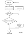
- Figures 3A and 3B in combination, comprise a flow chart showing steps in collecting lamp operational information, according to the preferred embodiment.
- a conventional lamp module 1 is shown with a printed circuit board (PCB) housing a lamp memory module 3 (non-volatile memory) and securely mounted to the same assembly as the lamp, lamp power connector and the mechanical support structure.
- a projector lamp will burn out over time, depending on operating conditions.
- the lamp memory module 3 records such operating conditions for later retrieval by the manufacturer.
- each lamp 5 is powered by ballast 7 under control of software operating in a system controller or CPU 9.
- Each lamp memory module 3 is connected to CPU 9 via a connector 11.
- a plurality of temperature sensors 13 are connected to the CPU 9, as is a real-time clock 15, with battery backup, discussed in greater detail below.
- the safety interlock system is shown according to one aspect of the present invention.
- This system provides protection against any attempt to operate the projector when the lamp 5 is not properly installed, and is less expensive, more reliable and fail-safe relative to prior art mechanical switches.
- the lamp 5 is powered from ballast 7, which is energized upon receiving a lamp enable signal from the CPU or control or 9. If power is disrupted, the ballast 7 does not attempt to energize the lamp 5, and no voltage is present on the lamp power connector.
- Ballast 7 includes an opto-isolator interface 17, which derives power from a SELV (Safety Extra Low Voltage) source, via the lamp memory module 3.
- SELV Safety Extra Low Voltage
- the interlock circuit trace 19 around the lamp memory module PCB becomes open-circuited. This disrupts power to the opto-isolator 17 which, in turn, disables the output of ballast 7, thereby placing the unit into a safe condition.
- a conduction path must be established via the circuit trace 19 around the lamp memory module 3. The interlock can only be overridden by inserting a conductive wire between the two outer pins of the interlock connector, which constitutes an intentional effort and requires a tool.
- a flow chart is provided showing steps of a software program executed by CPU 9 for collecting lamp operational data.
- lamp strike refers to the act of turning on the lamp 5. This process is known to be stressful on a lamp, and an excessive number of lamp strikes (i.e. turning the lamp on and off repeatedly) can shorten the life of the lamp. Lamp striking is controlled by a lamp driver (not shown) controlled by software within CPU 9.
- a lamp driver not shown
- the software issues a command to the lamp driver to strike the lamp. The software then waits for a response. If the lamp is successfully ignited, a positive indication is returned from the lamp driver. If the lamp fails to ignite, a negative response is returned. In the case of a lamp ignition failure, the software waits 90 seconds and then tries again. If the system is operated in "single lamp” mode, the software alternates between lamps until one lamp successfully ignites. The total number of attempted lamp strikes and successful lamp strikes are recorded in memory 3 upon occurrence, independently for each lamp 5.
- memory 3 is programmed with the serial number of the projector and data indicating the position of the lamp module 1 within the projector (projectors frequently include more than one lamp module, as shown in Figure 2A ).
- the serial number and position information stored in memory 3 are compared to the serial number of the projector and the current location of the lamp module 1, as shown in Figure 3 . In the event of any change, the serial number and position information is updated within memory 3.
- a plurality of sensors 13 are located throughout the projector, for measuring temperature.
- sensors 13 are disposed for detecting lamp compartment temperature, operating temperature of controller 9, and air exhaust temperature. These sensors are accessible to the software running within CPU 9.
- the software accesses timer 15 and waits 30 minutes for the system temperature to stabilize.
- the system temperature is then measured and stored within memory 3.
- system temperature is recorded only once a day such that if a lamp 5 is turned on and off multiple times within a 24 hour period, only the first set of measurements are recorded. If a lamp 5 is turned on and left on for more than 24 hours, at the end of that 24 hour. Another set of measurements is taken.
- the software is configured to store a plurality of sets of measurements (e.g. 30 or more), with only the most recent data have been retained.
- the highest and lowest operating temperatures are maintained it in memory 3 over the life of the lamp 5. Each time the temperature is updated, the date and time as read from the real-time clock 15 are also updated.
- power level at which a lamp 5 is operated is controlled by the lamp driver which, in turn, is controlled by the software running in CPU 9. Consequently, the software inherently knows what power the lamp is operating at. The cumulative total for lamp operation is tracked and the lamp our information is updated once per hour.
- power level is divided into three ranges (low, medium, and high), as shown in Figure 3B . According to the preferred embodiment, "a low power” is defined as operation between minimum power and 33%, “medium power” is defined as operation between 33% to 66%, and maximum scratch that "maximum power” is defined as operation between 66% to 100%.
- the lamp memory module 3 of the present invention stores operational data including a number of hours that a lamp 5 has run at low power, medium power and maximum power, the number of successful and attempted lamp strikes, the serial number of the last projector the lamp was installed in and the position where the lamp was installed (in a dual lamp system, the lamp and may be installed in either slot 1 or 2), the time and date of the last temperature measurement, all system temperatures for the last 30 days of operation, and at the maximum and minimum temperatures ever measured.
- the software may be modified and additional hardware items installed to track other operational data for the lamp 5.
Abstract
Description
- The present invention is directed to projection systems, and more particularly to a safety interlock system for a projector system.
- Digital projection systems are well known in the art, having been used for a number of years in many applications, including the film industry, military and civilian simulations, control rooms, etc. The lamp module in such projectors is expensive and subject to performance degradation over time as a result of usage at various power levels, number of lamp strikes as well as system temperatures at various locations. The inventors have realized that certain benefits can be derived from tracking lamp operational data, such as hours of usage, number of lamp strikes, temperatures, etc., and using this data to address future design issues such as operational differences between rental staging environments and fixed installations in cinema applications, legitimacy of customer equipment return claims, etc.
- Quite apart from the foregoing, the inventors have recognized that opening of the lamp access door exposes the high-voltage lamp module power. It is desirable to minimize risk of accidental electrocution when the lamp is not properly installed. According to the prior art, a mechanical push button type switch is provided for deactivating lamp power when the access door is open. However, the switch may be easily bypassed and also introduces cost into production of the lamp module.
- Therefore, according one aspect of the present invention, a lamp memory module is provided for recording lamp serial numbers, providing a 'lamp-inserted' interlock for preventing operation of the lamp when the lamp is not properly installed, and for collecting and storing lamp operational data such as lamp use (time), lamp strikes and various system temperatures.
- By encouraging customers to return spent lamp assemblies to the manufacturer, for example, to comply with a lamp recycling program (e.g. www.lamprecycle.org), the manufacturer is provided with useful data concerning field conditions regarding the use of their lamps.
- These together with other aspects and advantages which will be subsequently apparent, reside in the details of construction and operation as more fully hereinafter described and claimed, reference being had to the accompanying drawings forming a part hereof, wherein like numerals refer to like parts throughout.
-
Figure 1 shows a lamp memory module installed on a projector lamp assembly, according to the present invention; -
Figure 2A is a block diagram of the lamp memory module ofFigure 1 ; -
Figure 2B is a block diagram of a lamp-interlock function of the lamp memory module ofFigure 2A ; and -
Figures 3A and3B , in combination, comprise a flow chart showing steps in collecting lamp operational information, according to the preferred embodiment. - With reference to
Figure 1 , aconventional lamp module 1 is shown with a printed circuit board (PCB) housing a lamp memory module 3 (non-volatile memory) and securely mounted to the same assembly as the lamp, lamp power connector and the mechanical support structure. As indicated above, a projector lamp will burn out over time, depending on operating conditions. Thus, it is highly desirable to review the operating conditions to which a lamp has been exposed during its lifetime, in order to take such conditions into consideration when designing future lamps. As discussed in greater detail below, thelamp memory module 3 records such operating conditions for later retrieval by the manufacturer. In order to encourage users to return the spent lamps andmemory module 3 to the manufacturer, it is contemplated that a program be established for customers whereby prepaid postage is provided with each replacement module along with a request that the customer use existing packaging to return the spent module for recycling purposes (recycling is strongly encouraged because the lamps contain mercury). - As shown in
Figure 2 , eachlamp 5 is powered byballast 7 under control of software operating in a system controller orCPU 9. Eachlamp memory module 3 is connected toCPU 9 via aconnector 11. A plurality oftemperature sensors 13 are connected to theCPU 9, as is a real-time clock 15, with battery backup, discussed in greater detail below. - Turning briefly to the
Figure 2B , the safety interlock system is shown according to one aspect of the present invention. This system provides protection against any attempt to operate the projector when thelamp 5 is not properly installed, and is less expensive, more reliable and fail-safe relative to prior art mechanical switches. Thelamp 5 is powered fromballast 7, which is energized upon receiving a lamp enable signal from the CPU or control or 9. If power is disrupted, theballast 7 does not attempt to energize thelamp 5, and no voltage is present on the lamp power connector. Ballast 7 includes an opto-isolator interface 17, which derives power from a SELV (Safety Extra Low Voltage) source, via thelamp memory module 3. If thelamp module 1 is not installed, or if it is removed while the unit is operating, the interlock circuit trace 19 around the lamp memory module PCB becomes open-circuited. This disrupts power to the opto-isolator 17 which, in turn, disables the output ofballast 7, thereby placing the unit into a safe condition. In order to activate thelamp ballast 7, a conduction path must be established via the circuit trace 19 around thelamp memory module 3. The interlock can only be overridden by inserting a conductive wire between the two outer pins of the interlock connector, which constitutes an intentional effort and requires a tool. - With reference to
Figures 3A and3B , a flow chart is provided showing steps of a software program executed byCPU 9 for collecting lamp operational data. - The phrase "lamp strike" refers to the act of turning on the
lamp 5. This process is known to be stressful on a lamp, and an excessive number of lamp strikes (i.e. turning the lamp on and off repeatedly) can shorten the life of the lamp. Lamp striking is controlled by a lamp driver (not shown) controlled by software withinCPU 9. Turning toFigure 3A , when alamp 5 is turned on, the software issues a command to the lamp driver to strike the lamp. The software then waits for a response. If the lamp is successfully ignited, a positive indication is returned from the lamp driver. If the lamp fails to ignite, a negative response is returned. In the case of a lamp ignition failure, the software waits 90 seconds and then tries again. If the system is operated in "single lamp" mode, the software alternates between lamps until one lamp successfully ignites. The total number of attempted lamp strikes and successful lamp strikes are recorded inmemory 3 upon occurrence, independently for eachlamp 5. - At the time of manufacture,
memory 3 is programmed with the serial number of the projector and data indicating the position of thelamp module 1 within the projector (projectors frequently include more than one lamp module, as shown inFigure 2A ). When thelamp 5 is activated, the serial number and position information stored inmemory 3 are compared to the serial number of the projector and the current location of thelamp module 1, as shown inFigure 3 . In the event of any change, the serial number and position information is updated withinmemory 3. - As shown in
Figure 2A , a plurality ofsensors 13 are located throughout the projector, for measuring temperature. According to the preferred embodiment,sensors 13 are disposed for detecting lamp compartment temperature, operating temperature ofcontroller 9, and air exhaust temperature. These sensors are accessible to the software running withinCPU 9. When the lamp is turned on, the software accessestimer 15 and waits 30 minutes for the system temperature to stabilize. The system temperature is then measured and stored withinmemory 3. However, as shown inFigure 3A , system temperature is recorded only once a day such that if alamp 5 is turned on and off multiple times within a 24 hour period, only the first set of measurements are recorded. If alamp 5 is turned on and left on for more than 24 hours, at the end of that 24 hour. Another set of measurements is taken. If the lamp is not used at all, no records are made of projector temperature for that day. Preferably, the software is configured to store a plurality of sets of measurements (e.g. 30 or more), with only the most recent data have been retained. In addition, the highest and lowest operating temperatures are maintained it inmemory 3 over the life of thelamp 5. Each time the temperature is updated, the date and time as read from the real-time clock 15 are also updated. - The power level at which a
lamp 5 is operated, is controlled by the lamp driver which, in turn, is controlled by the software running inCPU 9. Consequently, the software inherently knows what power the lamp is operating at. The cumulative total for lamp operation is tracked and the lamp our information is updated once per hour. In order to reduce the amount of data storage, power level is divided into three ranges (low, medium, and high), as shown inFigure 3B . According to the preferred embodiment, "a low power" is defined as operation between minimum power and 33%, "medium power" is defined as operation between 33% to 66%, and maximum scratch that "maximum power" is defined as operation between 66% to 100%. - As indicated above, the
lamp memory module 3 of the present invention stores operational data including a number of hours that alamp 5 has run at low power, medium power and maximum power, the number of successful and attempted lamp strikes, the serial number of the last projector the lamp was installed in and the position where the lamp was installed (in a dual lamp system, the lamp and may be installed in eitherslot 1 or 2), the time and date of the last temperature measurement, all system temperatures for the last 30 days of operation, and at the maximum and minimum temperatures ever measured. It will be appreciated that, in addition to the foregoing data, the software may be modified and additional hardware items installed to track other operational data for thelamp 5. - The many features and advantages of the invention are apparent from the detailed specification and, thus, it is intended by the appended claims to cover all such features and advantages of the invention that fall within the true spirit and scope of the invention. Further, since numerous modifications and changes will readily occur to those skilled in the art, it is not desired to limit the invention to the exact construction and operation illustrated and described, and accordingly all suitable modifications and equivalents may be resorted to, falling within the scope of the invention.
Claims (3)
- Projector system having a lamp (5), a controller (9) and ballast (7) for powering said lamp (5) upon receipt of a lamp enable signal from said controller (9), characterized by a safety inter-lock system for deactivating said lamp (5) in the event said lamp (5) is not properly installed.
- The projector system of claim 1, wherein said ballast (7) derives power from a low voltage source within said controller (9), and delivered to said ballast (7) through a module (1) connected to said lamp (5) such that in the event said module (1) is not fully connected to said controller (9) then power is prevented from reaching said ballast (7).
- The projector system of claim 2, wherein said module (1) includes a first contact for connection to said low voltage source, a second contact for connection to said ballast (7), and a trace (19) between said contacts, such that in the event either one of said contacts is not properly connected said trace (19) becomes open-circuited.
Applications Claiming Priority (2)
| Application Number | Priority Date | Filing Date | Title |
|---|---|---|---|
| US11/239,166 US7841724B2 (en) | 2005-09-30 | 2005-09-30 | Method and apparatus for storing lamp data |
| EP06018051A EP1770436A1 (en) | 2005-09-30 | 2006-08-30 | Method and apparatus for storing lamp data |
Related Parent Applications (1)
| Application Number | Title | Priority Date | Filing Date |
|---|---|---|---|
| EP06018051.0 Division | 2006-08-30 |
Publications (1)
| Publication Number | Publication Date |
|---|---|
| EP2273311A1 true EP2273311A1 (en) | 2011-01-12 |
Family
ID=37192565
Family Applications (2)
| Application Number | Title | Priority Date | Filing Date |
|---|---|---|---|
| EP10182202A Withdrawn EP2273311A1 (en) | 2005-09-30 | 2006-08-30 | A safety interlock system for a projector system |
| EP06018051A Ceased EP1770436A1 (en) | 2005-09-30 | 2006-08-30 | Method and apparatus for storing lamp data |
Family Applications After (1)
| Application Number | Title | Priority Date | Filing Date |
|---|---|---|---|
| EP06018051A Ceased EP1770436A1 (en) | 2005-09-30 | 2006-08-30 | Method and apparatus for storing lamp data |
Country Status (3)
| Country | Link |
|---|---|
| US (2) | US7841724B2 (en) |
| EP (2) | EP2273311A1 (en) |
| JP (1) | JP2007102212A (en) |
Families Citing this family (13)
| Publication number | Priority date | Publication date | Assignee | Title |
|---|---|---|---|---|
| US7670010B2 (en) * | 2006-09-21 | 2010-03-02 | Dell Products L.P. | System and method for projector lamp safety interlock |
| JP4433320B2 (en) * | 2007-03-09 | 2010-03-17 | ソニー株式会社 | Projector and control method thereof |
| JP2008224870A (en) * | 2007-03-09 | 2008-09-25 | Sony Corp | Projector and its control method |
| JP5136824B2 (en) * | 2007-03-09 | 2013-02-06 | ソニー株式会社 | Projector and control method thereof |
| US8016433B2 (en) * | 2007-03-09 | 2011-09-13 | Sony Corporation | Projector and control method thereof |
| JP5109527B2 (en) * | 2007-08-03 | 2012-12-26 | ソニー株式会社 | Image forming apparatus, control method therefor, and program |
| JP5217375B2 (en) * | 2007-11-13 | 2013-06-19 | ソニー株式会社 | Multi-lamp projection display |
| JP2010113014A (en) * | 2008-11-04 | 2010-05-20 | Sanyo Electric Co Ltd | Projection image display apparatus |
| JP5362325B2 (en) * | 2008-11-05 | 2013-12-11 | 三洋電機株式会社 | Image display device and lamp unit |
| DE102008059483A1 (en) * | 2008-11-28 | 2010-06-10 | Osram Gesellschaft mit beschränkter Haftung | Integrated gas discharge lamp |
| US8294376B2 (en) * | 2010-05-30 | 2012-10-23 | Lumetric Lighting, Inc. | Fast reignition of a high intensity discharge lamp |
| JP2012141482A (en) * | 2011-01-05 | 2012-07-26 | Mitsubishi Electric Corp | Projection type display device |
| CN102799054B (en) * | 2012-06-20 | 2015-06-10 | 苏州佳世达光电有限公司 | Light source module, projector and setting method of projector |
Citations (4)
| Publication number | Priority date | Publication date | Assignee | Title |
|---|---|---|---|---|
| US5855488A (en) * | 1997-09-19 | 1999-01-05 | In Focus Systems, Inc. | Protection lamp safety interconnect apparatus and method |
| US6424097B1 (en) * | 2000-05-12 | 2002-07-23 | Infocus Corporation | Projection lamp safety interlock apparatus and method |
| US20030214638A1 (en) * | 2002-05-16 | 2003-11-20 | Nec Viewtechnology, Ltd. | Projector and lamp information management method used for the same |
| US20040124785A1 (en) * | 2000-07-21 | 2004-07-01 | Alexandrov Felix I. | Method and apparatus for arc detection and protection for electronic ballasts |
Family Cites Families (10)
| Publication number | Priority date | Publication date | Assignee | Title |
|---|---|---|---|---|
| JP3446912B2 (en) | 1995-02-17 | 2003-09-16 | ソニー株式会社 | Projector device |
| JP2000131758A (en) | 1998-10-26 | 2000-05-12 | Minolta Co Ltd | Projector |
| US6969960B2 (en) * | 1999-09-10 | 2005-11-29 | Belliveau Richard S | Image projection lighting device |
| US6373201B2 (en) * | 1999-12-28 | 2002-04-16 | Texas Instruments Incorporated | Reliable lamp life timer |
| JP2002341442A (en) * | 2001-05-16 | 2002-11-27 | Matsushita Electric Ind Co Ltd | Projection type image display |
| JP2003068478A (en) * | 2001-08-23 | 2003-03-07 | Olympus Optical Co Ltd | Light source device |
| US7048382B2 (en) * | 2002-10-26 | 2006-05-23 | Hewlett-Packard Development Company, L.P. | Recording length(s) of time high-temperature component operates in accordance with high-temperature policy |
| JP4251914B2 (en) * | 2003-05-13 | 2009-04-08 | 三菱電機株式会社 | Projection-type image display apparatus and discharge lamp information storage method thereof |
| US6956490B2 (en) * | 2003-07-28 | 2005-10-18 | Hewlett-Packard Development Company, L.P. | Projector with consumable component having memory device |
| US7377658B2 (en) * | 2005-04-26 | 2008-05-27 | Dell Products L.P. | System and method for automated projector lamp management |
-
2005
- 2005-09-30 US US11/239,166 patent/US7841724B2/en not_active Expired - Fee Related
-
2006
- 2006-08-30 EP EP10182202A patent/EP2273311A1/en not_active Withdrawn
- 2006-08-30 EP EP06018051A patent/EP1770436A1/en not_active Ceased
- 2006-09-21 JP JP2006256228A patent/JP2007102212A/en active Pending
-
2010
- 2010-10-18 US US12/906,391 patent/US8109641B2/en not_active Expired - Fee Related
Patent Citations (4)
| Publication number | Priority date | Publication date | Assignee | Title |
|---|---|---|---|---|
| US5855488A (en) * | 1997-09-19 | 1999-01-05 | In Focus Systems, Inc. | Protection lamp safety interconnect apparatus and method |
| US6424097B1 (en) * | 2000-05-12 | 2002-07-23 | Infocus Corporation | Projection lamp safety interlock apparatus and method |
| US20040124785A1 (en) * | 2000-07-21 | 2004-07-01 | Alexandrov Felix I. | Method and apparatus for arc detection and protection for electronic ballasts |
| US20030214638A1 (en) * | 2002-05-16 | 2003-11-20 | Nec Viewtechnology, Ltd. | Projector and lamp information management method used for the same |
Also Published As
| Publication number | Publication date |
|---|---|
| US20110032493A1 (en) | 2011-02-10 |
| US7841724B2 (en) | 2010-11-30 |
| JP2007102212A (en) | 2007-04-19 |
| US20070075647A1 (en) | 2007-04-05 |
| US8109641B2 (en) | 2012-02-07 |
| EP1770436A1 (en) | 2007-04-04 |
Similar Documents
| Publication | Publication Date | Title |
|---|---|---|
| US8109641B2 (en) | Safety interlock system for a projector system | |
| US6373201B2 (en) | Reliable lamp life timer | |
| EP2077481A2 (en) | Energy storage module | |
| US20050088100A1 (en) | Emergency lighting equipment with automatic charge/discharge and monitoring system | |
| JP2005332471A (en) | Disk array device | |
| US8084963B2 (en) | Management of rechargeable battery in an enclosed lighting module | |
| JP2008096140A (en) | Status detector for storage battery | |
| US20160133338A1 (en) | Self-testing data storage devices and methods | |
| JP3729961B2 (en) | Discharge lamp lighting circuit | |
| US9280654B1 (en) | Battery authentication circuit | |
| JPS6144344B2 (en) | ||
| CN1998270A (en) | Actuator comprising a memory part for a building management system | |
| JP6644923B1 (en) | Alarm | |
| CN112665100A (en) | Control method, computer-readable storage medium, and control device for air conditioner | |
| US8384292B2 (en) | Inrush current protection | |
| US8013753B2 (en) | Method for detecting operations of a power storage device and related power storage device | |
| JP2005093051A (en) | Inventory generation management device | |
| JP2007175373A (en) | Method for detecting opening/closing of lid in electronic apparatus, and lid fixing mechanism in electronic apparatus | |
| BR102020026550A2 (en) | 12V ELECTRICAL POWER SUPPLY AND CONTROL SYSTEM FOR AUTOMOTIVE INSTRUMENTS, EQUIPMENT AND PERIPHERALS AND EVENT RECORD DURING POWER SUPPLY | |
| KR100734101B1 (en) | An apparatus for controlling battery backup of a banking system | |
| JP2022002197A (en) | Lighting device and illumination apparatus | |
| JP2834619B2 (en) | Gas leak alarm device | |
| JP5688337B2 (en) | Battery life check device | |
| JPH079831B2 (en) | Card type lighting control device | |
| JP2020123311A (en) | Alarm |
Legal Events
| Date | Code | Title | Description |
|---|---|---|---|
| PUAI | Public reference made under article 153(3) epc to a published international application that has entered the european phase |
Free format text: ORIGINAL CODE: 0009012 |
|
| AC | Divisional application: reference to earlier application |
Ref document number: 1770436 Country of ref document: EP Kind code of ref document: P |
|
| AK | Designated contracting states |
Kind code of ref document: A1 Designated state(s): AT BE BG CH CY CZ DE DK EE ES FI FR GB GR HU IE IS IT LI LT LU LV MC NL PL PT RO SE SI SK TR |
|
| 17P | Request for examination filed |
Effective date: 20110702 |
|
| 17Q | First examination report despatched |
Effective date: 20120921 |
|
| STAA | Information on the status of an ep patent application or granted ep patent |
Free format text: STATUS: THE APPLICATION IS DEEMED TO BE WITHDRAWN |
|
| 18D | Application deemed to be withdrawn |
Effective date: 20150716 |