EP2272920A1 - Dye for dye-sensitized solar cell and dye-sensitized solar cell including the same - Google Patents
Dye for dye-sensitized solar cell and dye-sensitized solar cell including the same Download PDFInfo
- Publication number
- EP2272920A1 EP2272920A1 EP10162203A EP10162203A EP2272920A1 EP 2272920 A1 EP2272920 A1 EP 2272920A1 EP 10162203 A EP10162203 A EP 10162203A EP 10162203 A EP10162203 A EP 10162203A EP 2272920 A1 EP2272920 A1 EP 2272920A1
- Authority
- EP
- European Patent Office
- Prior art keywords
- substituted
- dye
- unsubstituted
- group
- solar cell
- Prior art date
- Legal status (The legal status is an assumption and is not a legal conclusion. Google has not performed a legal analysis and makes no representation as to the accuracy of the status listed.)
- Granted
Links
- 125000000524 functional group Chemical group 0.000 claims abstract description 24
- 125000003118 aryl group Chemical group 0.000 claims abstract description 19
- 125000001931 aliphatic group Chemical group 0.000 claims abstract description 18
- 125000000623 heterocyclic group Chemical group 0.000 claims abstract description 18
- 125000002887 hydroxy group Chemical group [H]O* 0.000 claims abstract description 17
- 229910052739 hydrogen Inorganic materials 0.000 claims abstract description 15
- 239000001257 hydrogen Substances 0.000 claims abstract description 15
- 125000002723 alicyclic group Chemical group 0.000 claims abstract description 11
- 229910052760 oxygen Inorganic materials 0.000 claims abstract description 10
- 229910052717 sulfur Inorganic materials 0.000 claims abstract description 10
- 230000002378 acidificating effect Effects 0.000 claims abstract description 9
- 150000002431 hydrogen Chemical class 0.000 claims abstract description 9
- UFHFLCQGNIYNRP-UHFFFAOYSA-N Hydrogen Chemical compound [H][H] UFHFLCQGNIYNRP-UHFFFAOYSA-N 0.000 claims abstract description 6
- 230000031700 light absorption Effects 0.000 claims description 29
- 239000004065 semiconductor Substances 0.000 claims description 27
- 239000000758 substrate Substances 0.000 claims description 25
- 239000003792 electrolyte Substances 0.000 claims description 20
- 239000000654 additive Substances 0.000 claims description 16
- 230000000996 additive effect Effects 0.000 claims description 16
- 125000000217 alkyl group Chemical group 0.000 claims description 10
- 125000003178 carboxy group Chemical group [H]OC(*)=O 0.000 claims description 10
- 125000000753 cycloalkyl group Chemical group 0.000 claims description 8
- 125000003342 alkenyl group Chemical group 0.000 claims description 7
- 125000004390 alkyl sulfonyl group Chemical group 0.000 claims description 7
- 125000004414 alkyl thio group Chemical group 0.000 claims description 7
- 125000002252 acyl group Chemical group 0.000 claims description 6
- 125000004423 acyloxy group Chemical group 0.000 claims description 6
- 125000003545 alkoxy group Chemical group 0.000 claims description 6
- 125000004453 alkoxycarbonyl group Chemical group 0.000 claims description 6
- 125000005138 alkoxysulfonyl group Chemical group 0.000 claims description 6
- 125000003710 aryl alkyl group Chemical group 0.000 claims description 6
- 125000004391 aryl sulfonyl group Chemical group 0.000 claims description 6
- 125000004104 aryloxy group Chemical group 0.000 claims description 6
- 125000001188 haloalkyl group Chemical group 0.000 claims description 6
- KXGVEGMKQFWNSR-LLQZFEROSA-N deoxycholic acid Chemical compound C([C@H]1CC2)[C@H](O)CC[C@]1(C)[C@@H]1[C@@H]2[C@@H]2CC[C@H]([C@@H](CCC(O)=O)C)[C@@]2(C)[C@@H](O)C1 KXGVEGMKQFWNSR-LLQZFEROSA-N 0.000 claims description 5
- 229960003964 deoxycholic acid Drugs 0.000 claims description 5
- KXGVEGMKQFWNSR-UHFFFAOYSA-N deoxycholic acid Natural products C1CC2CC(O)CCC2(C)C2C1C1CCC(C(CCC(O)=O)C)C1(C)C(O)C2 KXGVEGMKQFWNSR-UHFFFAOYSA-N 0.000 claims description 5
- 125000003983 fluorenyl group Chemical group C1(=CC=CC=2C3=CC=CC=C3CC12)* 0.000 claims description 5
- 125000004093 cyano group Chemical group *C#N 0.000 claims description 4
- 229910052736 halogen Inorganic materials 0.000 claims description 4
- 150000002367 halogens Chemical class 0.000 claims description 4
- 125000000449 nitro group Chemical group [O-][N+](*)=O 0.000 claims description 4
- 125000002924 primary amino group Chemical group [H]N([H])* 0.000 claims description 4
- RZUDZAJRBFRQLS-UHFFFAOYSA-N 2-dodecylpropanedioic acid Chemical compound CCCCCCCCCCCCC(C(O)=O)C(O)=O RZUDZAJRBFRQLS-UHFFFAOYSA-N 0.000 claims description 3
- XMIIGOLPHOKFCH-UHFFFAOYSA-N 3-phenylpropionic acid Chemical compound OC(=O)CCC1=CC=CC=C1 XMIIGOLPHOKFCH-UHFFFAOYSA-N 0.000 claims description 3
- NBIIXXVUZAFLBC-UHFFFAOYSA-N Phosphoric acid Chemical group OP(O)(O)=O NBIIXXVUZAFLBC-UHFFFAOYSA-N 0.000 claims description 3
- SVMUEEINWGBIPD-UHFFFAOYSA-N dodecylphosphonic acid Chemical compound CCCCCCCCCCCCP(O)(O)=O SVMUEEINWGBIPD-UHFFFAOYSA-N 0.000 claims description 3
- 125000000542 sulfonic acid group Chemical group 0.000 claims description 3
- 239000010410 layer Substances 0.000 description 61
- GWEVSGVZZGPLCZ-UHFFFAOYSA-N Titan oxide Chemical compound O=[Ti]=O GWEVSGVZZGPLCZ-UHFFFAOYSA-N 0.000 description 22
- 150000001875 compounds Chemical class 0.000 description 19
- 239000006185 dispersion Substances 0.000 description 18
- 230000000052 comparative effect Effects 0.000 description 16
- 238000006243 chemical reaction Methods 0.000 description 14
- -1 e.g. Chemical compound 0.000 description 13
- WEVYAHXRMPXWCK-UHFFFAOYSA-N Acetonitrile Chemical compound CC#N WEVYAHXRMPXWCK-UHFFFAOYSA-N 0.000 description 12
- YMWUJEATGCHHMB-UHFFFAOYSA-N Dichloromethane Chemical compound ClCCl YMWUJEATGCHHMB-UHFFFAOYSA-N 0.000 description 12
- 239000000243 solution Substances 0.000 description 12
- XOLBLPGZBRYERU-UHFFFAOYSA-N tin dioxide Chemical compound O=[Sn]=O XOLBLPGZBRYERU-UHFFFAOYSA-N 0.000 description 12
- 239000000463 material Substances 0.000 description 11
- IHXWECHPYNPJRR-UHFFFAOYSA-N 3-hydroxycyclobut-2-en-1-one Chemical group OC1=CC(=O)C1 IHXWECHPYNPJRR-UHFFFAOYSA-N 0.000 description 10
- BASFCYQUMIYNBI-UHFFFAOYSA-N platinum Substances [Pt] BASFCYQUMIYNBI-UHFFFAOYSA-N 0.000 description 9
- FCEHBMOGCRZNNI-UHFFFAOYSA-N 1-benzothiophene Chemical class C1=CC=C2SC=CC2=C1 FCEHBMOGCRZNNI-UHFFFAOYSA-N 0.000 description 8
- LFQSCWFLJHTTHZ-UHFFFAOYSA-N Ethanol Chemical compound CCO LFQSCWFLJHTTHZ-UHFFFAOYSA-N 0.000 description 8
- CSNNHWWHGAXBCP-UHFFFAOYSA-L Magnesium sulfate Chemical compound [Mg+2].[O-][S+2]([O-])([O-])[O-] CSNNHWWHGAXBCP-UHFFFAOYSA-L 0.000 description 8
- 238000010438 heat treatment Methods 0.000 description 8
- 230000033116 oxidation-reduction process Effects 0.000 description 8
- OGIDPMRJRNCKJF-UHFFFAOYSA-N titanium oxide Inorganic materials [Ti]=O OGIDPMRJRNCKJF-UHFFFAOYSA-N 0.000 description 8
- 238000001035 drying Methods 0.000 description 7
- 238000000034 method Methods 0.000 description 7
- 239000002245 particle Substances 0.000 description 7
- IJGRMHOSHXDMSA-UHFFFAOYSA-N Atomic nitrogen Chemical compound N#N IJGRMHOSHXDMSA-UHFFFAOYSA-N 0.000 description 6
- NINIDFKCEFEMDL-UHFFFAOYSA-N Sulfur Chemical compound [S] NINIDFKCEFEMDL-UHFFFAOYSA-N 0.000 description 6
- XLOMVQKBTHCTTD-UHFFFAOYSA-N Zinc monoxide Chemical compound [Zn]=O XLOMVQKBTHCTTD-UHFFFAOYSA-N 0.000 description 6
- QVGXLLKOCUKJST-UHFFFAOYSA-N atomic oxygen Chemical compound [O] QVGXLLKOCUKJST-UHFFFAOYSA-N 0.000 description 6
- 239000010408 film Substances 0.000 description 6
- 239000011521 glass Substances 0.000 description 6
- 239000012044 organic layer Substances 0.000 description 6
- 239000001301 oxygen Substances 0.000 description 6
- 239000000126 substance Substances 0.000 description 6
- 239000011593 sulfur Substances 0.000 description 6
- 229920001169 thermoplastic Polymers 0.000 description 6
- 229910001887 tin oxide Inorganic materials 0.000 description 6
- WFDIJRYMOXRFFG-UHFFFAOYSA-N Acetic anhydride Chemical compound CC(=O)OC(C)=O WFDIJRYMOXRFFG-UHFFFAOYSA-N 0.000 description 5
- 239000004020 conductor Substances 0.000 description 5
- 238000004519 manufacturing process Methods 0.000 description 5
- 239000011259 mixed solution Substances 0.000 description 5
- 229920003023 plastic Polymers 0.000 description 5
- 239000004033 plastic Substances 0.000 description 5
- 229920000642 polymer Polymers 0.000 description 5
- 239000002904 solvent Substances 0.000 description 5
- YYXZQUOJBJOARI-UHFFFAOYSA-M 1-hexyl-2,3-dimethylimidazol-3-ium;iodide Chemical compound [I-].CCCCCCN1C=C[N+](C)=C1C YYXZQUOJBJOARI-UHFFFAOYSA-M 0.000 description 4
- ZMANZCXQSJIPKH-UHFFFAOYSA-N Triethylamine Chemical compound CCN(CC)CC ZMANZCXQSJIPKH-UHFFFAOYSA-N 0.000 description 4
- 239000000853 adhesive Substances 0.000 description 4
- 230000008901 benefit Effects 0.000 description 4
- 238000000576 coating method Methods 0.000 description 4
- 229910052943 magnesium sulfate Inorganic materials 0.000 description 4
- 229910052757 nitrogen Inorganic materials 0.000 description 4
- 229910052697 platinum Inorganic materials 0.000 description 4
- LJXQPZWIHJMPQQ-UHFFFAOYSA-N pyrimidin-2-amine Chemical compound NC1=NC=CC=N1 LJXQPZWIHJMPQQ-UHFFFAOYSA-N 0.000 description 4
- UHOVQNZJYSORNB-UHFFFAOYSA-N Benzene Chemical compound C1=CC=CC=C1 UHOVQNZJYSORNB-UHFFFAOYSA-N 0.000 description 3
- OKTJSMMVPCPJKN-UHFFFAOYSA-N Carbon Chemical compound [C] OKTJSMMVPCPJKN-UHFFFAOYSA-N 0.000 description 3
- 125000000304 alkynyl group Chemical group 0.000 description 3
- IANQTJSKSUMEQM-UHFFFAOYSA-N benzofuran Natural products C1=CC=C2OC=CC2=C1 IANQTJSKSUMEQM-UHFFFAOYSA-N 0.000 description 3
- 229910052799 carbon Inorganic materials 0.000 description 3
- 239000003086 colorant Substances 0.000 description 3
- 150000001907 coumarones Chemical class 0.000 description 3
- 125000004438 haloalkoxy group Chemical group 0.000 description 3
- 125000001072 heteroaryl group Chemical group 0.000 description 3
- 239000002905 metal composite material Substances 0.000 description 3
- 239000012046 mixed solvent Substances 0.000 description 3
- 230000008569 process Effects 0.000 description 3
- 238000006479 redox reaction Methods 0.000 description 3
- 238000010898 silica gel chromatography Methods 0.000 description 3
- 229910052710 silicon Inorganic materials 0.000 description 3
- 238000004544 sputter deposition Methods 0.000 description 3
- 239000004408 titanium dioxide Substances 0.000 description 3
- XLYOFNOQVPJJNP-UHFFFAOYSA-N water Substances O XLYOFNOQVPJJNP-UHFFFAOYSA-N 0.000 description 3
- 239000011787 zinc oxide Substances 0.000 description 3
- HPLYCXVKRFOUIK-UHFFFAOYSA-N 2,3,3-trimethyl-1-octylindol-1-ium-5-carboxylic acid;iodide Chemical compound [I-].OC(=O)C1=CC=C2[N+](CCCCCCCC)=C(C)C(C)(C)C2=C1 HPLYCXVKRFOUIK-UHFFFAOYSA-N 0.000 description 2
- OZOYNWQSFNTBNE-UHFFFAOYSA-N 3-methyl-4-propan-2-yloxycyclobut-3-ene-1,2-dione Chemical compound CC(C)OC1=C(C)C(=O)C1=O OZOYNWQSFNTBNE-UHFFFAOYSA-N 0.000 description 2
- KSRHKOLSOXXCAT-UHFFFAOYSA-N 4-[bis(9,9-dimethylfluoren-2-yl)amino]benzaldehyde Chemical compound C1=C2C(C)(C)C3=CC=CC=C3C2=CC=C1N(C=1C=C2C(C)(C)C3=CC=CC=C3C2=CC=1)C1=CC=C(C=O)C=C1 KSRHKOLSOXXCAT-UHFFFAOYSA-N 0.000 description 2
- 229920002284 Cellulose triacetate Polymers 0.000 description 2
- VEXZGXHMUGYJMC-UHFFFAOYSA-N Hydrochloric acid Chemical compound Cl VEXZGXHMUGYJMC-UHFFFAOYSA-N 0.000 description 2
- 229920002153 Hydroxypropyl cellulose Polymers 0.000 description 2
- LRHPLDYGYMQRHN-UHFFFAOYSA-N N-Butanol Chemical compound CCCCO LRHPLDYGYMQRHN-UHFFFAOYSA-N 0.000 description 2
- 229920003171 Poly (ethylene oxide) Polymers 0.000 description 2
- 239000002202 Polyethylene glycol Substances 0.000 description 2
- 239000004642 Polyimide Substances 0.000 description 2
- 239000004743 Polypropylene Substances 0.000 description 2
- 239000004372 Polyvinyl alcohol Substances 0.000 description 2
- NNLVGZFZQQXQNW-ADJNRHBOSA-N [(2r,3r,4s,5r,6s)-4,5-diacetyloxy-3-[(2s,3r,4s,5r,6r)-3,4,5-triacetyloxy-6-(acetyloxymethyl)oxan-2-yl]oxy-6-[(2r,3r,4s,5r,6s)-4,5,6-triacetyloxy-2-(acetyloxymethyl)oxan-3-yl]oxyoxan-2-yl]methyl acetate Chemical compound O([C@@H]1O[C@@H]([C@H]([C@H](OC(C)=O)[C@H]1OC(C)=O)O[C@H]1[C@@H]([C@@H](OC(C)=O)[C@H](OC(C)=O)[C@@H](COC(C)=O)O1)OC(C)=O)COC(=O)C)[C@@H]1[C@@H](COC(C)=O)O[C@@H](OC(C)=O)[C@H](OC(C)=O)[C@H]1OC(C)=O NNLVGZFZQQXQNW-ADJNRHBOSA-N 0.000 description 2
- NPNMHHNXCILFEF-UHFFFAOYSA-N [F].[Sn]=O Chemical compound [F].[Sn]=O NPNMHHNXCILFEF-UHFFFAOYSA-N 0.000 description 2
- 238000004220 aggregation Methods 0.000 description 2
- 230000002776 aggregation Effects 0.000 description 2
- 125000004450 alkenylene group Chemical group 0.000 description 2
- 125000002947 alkylene group Chemical group 0.000 description 2
- PNEYBMLMFCGWSK-UHFFFAOYSA-N aluminium oxide Inorganic materials [O-2].[O-2].[O-2].[Al+3].[Al+3] PNEYBMLMFCGWSK-UHFFFAOYSA-N 0.000 description 2
- 125000000732 arylene group Chemical group 0.000 description 2
- 239000011230 binding agent Substances 0.000 description 2
- 239000003054 catalyst Substances 0.000 description 2
- 239000011248 coating agent Substances 0.000 description 2
- 229910052593 corundum Inorganic materials 0.000 description 2
- ZYGHJZDHTFUPRJ-UHFFFAOYSA-N coumarin Chemical compound C1=CC=C2OC(=O)C=CC2=C1 ZYGHJZDHTFUPRJ-UHFFFAOYSA-N 0.000 description 2
- 239000006059 cover glass Substances 0.000 description 2
- 125000000392 cycloalkenyl group Chemical group 0.000 description 2
- 125000002993 cycloalkylene group Chemical group 0.000 description 2
- 238000000151 deposition Methods 0.000 description 2
- 238000007606 doctor blade method Methods 0.000 description 2
- QZQVBEXLDFYHSR-UHFFFAOYSA-N gallium(III) oxide Inorganic materials O=[Ga]O[Ga]=O QZQVBEXLDFYHSR-UHFFFAOYSA-N 0.000 description 2
- 229910052737 gold Inorganic materials 0.000 description 2
- 230000005283 ground state Effects 0.000 description 2
- 239000001863 hydroxypropyl cellulose Substances 0.000 description 2
- 235000010977 hydroxypropyl cellulose Nutrition 0.000 description 2
- 229940071676 hydroxypropylcellulose Drugs 0.000 description 2
- 229910052738 indium Inorganic materials 0.000 description 2
- AMGQUBHHOARCQH-UHFFFAOYSA-N indium;oxotin Chemical compound [In].[Sn]=O AMGQUBHHOARCQH-UHFFFAOYSA-N 0.000 description 2
- 238000004768 lowest unoccupied molecular orbital Methods 0.000 description 2
- 238000005259 measurement Methods 0.000 description 2
- 229910044991 metal oxide Inorganic materials 0.000 description 2
- 150000004706 metal oxides Chemical class 0.000 description 2
- ZKATWMILCYLAPD-UHFFFAOYSA-N niobium pentoxide Chemical compound O=[Nb](=O)O[Nb](=O)=O ZKATWMILCYLAPD-UHFFFAOYSA-N 0.000 description 2
- 238000005240 physical vapour deposition Methods 0.000 description 2
- 229920001223 polyethylene glycol Polymers 0.000 description 2
- 229920000139 polyethylene terephthalate Polymers 0.000 description 2
- 239000005020 polyethylene terephthalate Substances 0.000 description 2
- 229920001721 polyimide Polymers 0.000 description 2
- 229920001155 polypropylene Polymers 0.000 description 2
- 229920002451 polyvinyl alcohol Polymers 0.000 description 2
- 229920000036 polyvinylpyrrolidone Polymers 0.000 description 2
- 239000001267 polyvinylpyrrolidone Substances 0.000 description 2
- 235000013855 polyvinylpyrrolidone Nutrition 0.000 description 2
- 238000002360 preparation method Methods 0.000 description 2
- 238000010992 reflux Methods 0.000 description 2
- 229910052707 ruthenium Inorganic materials 0.000 description 2
- 238000005507 spraying Methods 0.000 description 2
- 125000000335 thiazolyl group Chemical group 0.000 description 2
- 230000032258 transport Effects 0.000 description 2
- 238000005406 washing Methods 0.000 description 2
- 229910052724 xenon Inorganic materials 0.000 description 2
- FHNFHKCVQCLJFQ-UHFFFAOYSA-N xenon atom Chemical compound [Xe] FHNFHKCVQCLJFQ-UHFFFAOYSA-N 0.000 description 2
- 229910001845 yogo sapphire Inorganic materials 0.000 description 2
- RYHBNJHYFVUHQT-UHFFFAOYSA-N 1,4-Dioxane Chemical compound C1COCCO1 RYHBNJHYFVUHQT-UHFFFAOYSA-N 0.000 description 1
- YBYIRNPNPLQARY-UHFFFAOYSA-N 1H-indene Natural products C1=CC=C2CC=CC2=C1 YBYIRNPNPLQARY-UHFFFAOYSA-N 0.000 description 1
- ZCYVEMRRCGMTRW-UHFFFAOYSA-N 7553-56-2 Chemical compound [I] ZCYVEMRRCGMTRW-UHFFFAOYSA-N 0.000 description 1
- ROFVEXUMMXZLPA-UHFFFAOYSA-N Bipyridyl Chemical class N1=CC=CC=C1C1=CC=CC=N1 ROFVEXUMMXZLPA-UHFFFAOYSA-N 0.000 description 1
- 0 CCCCCCCC(*)[N+](c1c(C2(C)C)cc(**)cc1)=C2C=C1C([O-])=C(C=Cc(cc2)ccc2N(c(cc2C3(C)C)ccc2-c2c3cccc2)c2ccc3-c4ccccc4C(C)(C)c3c2)C1=O Chemical compound CCCCCCCC(*)[N+](c1c(C2(C)C)cc(**)cc1)=C2C=C1C([O-])=C(C=Cc(cc2)ccc2N(c(cc2C3(C)C)ccc2-c2c3cccc2)c2ccc3-c4ccccc4C(C)(C)c3c2)C1=O 0.000 description 1
- VGGSQFUCUMXWEO-UHFFFAOYSA-N Ethene Chemical compound C=C VGGSQFUCUMXWEO-UHFFFAOYSA-N 0.000 description 1
- 239000005977 Ethylene Substances 0.000 description 1
- KJTLSVCANCCWHF-UHFFFAOYSA-N Ruthenium Chemical class [Ru] KJTLSVCANCCWHF-UHFFFAOYSA-N 0.000 description 1
- 229920003182 Surlyn® Polymers 0.000 description 1
- 229910008559 TiSrO3 Inorganic materials 0.000 description 1
- 239000007983 Tris buffer Substances 0.000 description 1
- 238000002835 absorbance Methods 0.000 description 1
- 239000002253 acid Substances 0.000 description 1
- 125000000641 acridinyl group Chemical group C1(=CC=CC2=NC3=CC=CC=C3C=C12)* 0.000 description 1
- 239000005456 alcohol based solvent Substances 0.000 description 1
- 125000005428 anthryl group Chemical group [H]C1=C([H])C([H])=C2C([H])=C3C(*)=C([H])C([H])=C([H])C3=C([H])C2=C1[H] 0.000 description 1
- 125000004429 atom Chemical group 0.000 description 1
- RFRXIWQYSOIBDI-UHFFFAOYSA-N benzarone Chemical compound CCC=1OC2=CC=CC=C2C=1C(=O)C1=CC=C(O)C=C1 RFRXIWQYSOIBDI-UHFFFAOYSA-N 0.000 description 1
- 125000004618 benzofuryl group Chemical group O1C(=CC2=C1C=CC=C2)* 0.000 description 1
- 125000001164 benzothiazolyl group Chemical group S1C(=NC2=C1C=CC=C2)* 0.000 description 1
- 125000004541 benzoxazolyl group Chemical group O1C(=NC2=C1C=CC=C2)* 0.000 description 1
- 230000015572 biosynthetic process Effects 0.000 description 1
- 125000000609 carbazolyl group Chemical group C1(=CC=CC=2C3=CC=CC=C3NC12)* 0.000 description 1
- 239000001913 cellulose Substances 0.000 description 1
- 229920002678 cellulose Polymers 0.000 description 1
- 239000002131 composite material Substances 0.000 description 1
- 229920001940 conductive polymer Polymers 0.000 description 1
- 229910052802 copper Inorganic materials 0.000 description 1
- 229960000956 coumarin Drugs 0.000 description 1
- 235000001671 coumarin Nutrition 0.000 description 1
- 238000007598 dipping method Methods 0.000 description 1
- 238000000313 electron-beam-induced deposition Methods 0.000 description 1
- 238000009713 electroplating Methods 0.000 description 1
- 238000005516 engineering process Methods 0.000 description 1
- 239000003822 epoxy resin Substances 0.000 description 1
- 238000011156 evaluation Methods 0.000 description 1
- 238000011049 filling Methods 0.000 description 1
- 239000002803 fossil fuel Substances 0.000 description 1
- 125000003838 furazanyl group Chemical group 0.000 description 1
- 125000002541 furyl group Chemical group 0.000 description 1
- 229910052733 gallium Inorganic materials 0.000 description 1
- 229910052732 germanium Inorganic materials 0.000 description 1
- 125000005842 heteroatom Chemical group 0.000 description 1
- XMBWDFGMSWQBCA-UHFFFAOYSA-N hydrogen iodide Chemical compound I XMBWDFGMSWQBCA-UHFFFAOYSA-N 0.000 description 1
- 230000002209 hydrophobic effect Effects 0.000 description 1
- 125000002883 imidazolyl group Chemical group 0.000 description 1
- 125000003454 indenyl group Chemical group C1(C=CC2=CC=CC=C12)* 0.000 description 1
- 125000001041 indolyl group Chemical group 0.000 description 1
- 239000011810 insulating material Substances 0.000 description 1
- 229910052740 iodine Inorganic materials 0.000 description 1
- 239000011630 iodine Substances 0.000 description 1
- 150000002500 ions Chemical class 0.000 description 1
- 229910052741 iridium Inorganic materials 0.000 description 1
- 125000000904 isoindolyl group Chemical group C=1(NC=C2C=CC=CC12)* 0.000 description 1
- 125000005956 isoquinolyl group Chemical group 0.000 description 1
- 235000019341 magnesium sulphate Nutrition 0.000 description 1
- 229910021421 monocrystalline silicon Inorganic materials 0.000 description 1
- 125000001624 naphthyl group Chemical group 0.000 description 1
- 229910052759 nickel Inorganic materials 0.000 description 1
- 125000002347 octyl group Chemical group [H]C([*])([H])C([H])([H])C([H])([H])C([H])([H])C([H])([H])C([H])([H])C([H])([H])C([H])([H])[H] 0.000 description 1
- 230000003287 optical effect Effects 0.000 description 1
- 150000002894 organic compounds Chemical class 0.000 description 1
- 239000011368 organic material Substances 0.000 description 1
- 229920000620 organic polymer Polymers 0.000 description 1
- 125000001715 oxadiazolyl group Chemical group 0.000 description 1
- 125000002971 oxazolyl group Chemical group 0.000 description 1
- 230000003647 oxidation Effects 0.000 description 1
- 238000007254 oxidation reaction Methods 0.000 description 1
- SOQBVABWOPYFQZ-UHFFFAOYSA-N oxygen(2-);titanium(4+) Chemical compound [O-2].[O-2].[Ti+4] SOQBVABWOPYFQZ-UHFFFAOYSA-N 0.000 description 1
- 229910052763 palladium Inorganic materials 0.000 description 1
- 125000002080 perylenyl group Chemical group C1(=CC=C2C=CC=C3C4=CC=CC5=CC=CC(C1=C23)=C45)* 0.000 description 1
- 239000003208 petroleum Substances 0.000 description 1
- 125000004934 phenanthridinyl group Chemical group C1(=CC=CC2=NC=C3C=CC=CC3=C12)* 0.000 description 1
- 125000004625 phenanthrolinyl group Chemical group N1=C(C=CC2=CC=C3C=CC=NC3=C12)* 0.000 description 1
- 125000005561 phenanthryl group Chemical group 0.000 description 1
- 125000001791 phenazinyl group Chemical group C1(=CC=CC2=NC3=CC=CC=C3N=C12)* 0.000 description 1
- 125000001484 phenothiazinyl group Chemical group C1(=CC=CC=2SC3=CC=CC=C3NC12)* 0.000 description 1
- 125000001644 phenoxazinyl group Chemical group C1(=CC=CC=2OC3=CC=CC=C3NC12)* 0.000 description 1
- 125000001997 phenyl group Chemical group [H]C1=C([H])C([H])=C(*)C([H])=C1[H] 0.000 description 1
- NSFSLUUZQIAOOX-LDCXZXNSSA-N pheophorbide a Chemical compound N1C(C=C2[C@H]([C@H](CCC(O)=O)C(=N2)C2=C3NC(=C4)C(C)=C3C(=O)[C@@H]2C(=O)OC)C)=C(C)C(C=C)=C1C=C1C(C)=C(CC)C4=N1 NSFSLUUZQIAOOX-LDCXZXNSSA-N 0.000 description 1
- 229910052698 phosphorus Inorganic materials 0.000 description 1
- CLSUSRZJUQMOHH-UHFFFAOYSA-L platinum dichloride Chemical compound Cl[Pt]Cl CLSUSRZJUQMOHH-UHFFFAOYSA-L 0.000 description 1
- 229920000515 polycarbonate Polymers 0.000 description 1
- 239000004417 polycarbonate Substances 0.000 description 1
- 229920000647 polyepoxide Polymers 0.000 description 1
- 239000011112 polyethylene naphthalate Substances 0.000 description 1
- 150000004032 porphyrins Chemical class 0.000 description 1
- 125000003373 pyrazinyl group Chemical group 0.000 description 1
- 125000001725 pyrenyl group Chemical group 0.000 description 1
- 125000004076 pyridyl group Chemical group 0.000 description 1
- 125000000168 pyrrolyl group Chemical group 0.000 description 1
- 125000005493 quinolyl group Chemical group 0.000 description 1
- 125000001567 quinoxalinyl group Chemical group N1=C(C=NC2=CC=CC=C12)* 0.000 description 1
- 238000006722 reduction reaction Methods 0.000 description 1
- 238000011160 research Methods 0.000 description 1
- 230000027756 respiratory electron transport chain Effects 0.000 description 1
- 229910052703 rhodium Inorganic materials 0.000 description 1
- 150000003839 salts Chemical class 0.000 description 1
- 238000007650 screen-printing Methods 0.000 description 1
- 238000007789 sealing Methods 0.000 description 1
- 238000000926 separation method Methods 0.000 description 1
- 239000010703 silicon Substances 0.000 description 1
- 229910052709 silver Inorganic materials 0.000 description 1
- 238000005245 sintering Methods 0.000 description 1
- 238000001179 sorption measurement Methods 0.000 description 1
- 238000004528 spin coating Methods 0.000 description 1
- 125000001424 substituent group Chemical group 0.000 description 1
- 125000000472 sulfonyl group Chemical group *S(*)(=O)=O 0.000 description 1
- 238000003786 synthesis reaction Methods 0.000 description 1
- 125000001935 tetracenyl group Chemical group C1(=CC=CC2=CC3=CC4=CC=CC=C4C=C3C=C12)* 0.000 description 1
- 125000001544 thienyl group Chemical group 0.000 description 1
- 239000010409 thin film Substances 0.000 description 1
- 229910052719 titanium Inorganic materials 0.000 description 1
- 239000010936 titanium Substances 0.000 description 1
- 125000003944 tolyl group Chemical group 0.000 description 1
- 238000012546 transfer Methods 0.000 description 1
- 229910000314 transition metal oxide Inorganic materials 0.000 description 1
- WRTMQOHKMFDUKX-UHFFFAOYSA-N triiodide Chemical compound I[I-]I WRTMQOHKMFDUKX-UHFFFAOYSA-N 0.000 description 1
- ZNOKGRXACCSDPY-UHFFFAOYSA-N tungsten(VI) oxide Inorganic materials O=[W](=O)=O ZNOKGRXACCSDPY-UHFFFAOYSA-N 0.000 description 1
- 125000005023 xylyl group Chemical group 0.000 description 1
Images

Classifications
-
- C—CHEMISTRY; METALLURGY
- C09—DYES; PAINTS; POLISHES; NATURAL RESINS; ADHESIVES; COMPOSITIONS NOT OTHERWISE PROVIDED FOR; APPLICATIONS OF MATERIALS NOT OTHERWISE PROVIDED FOR
- C09B—ORGANIC DYES OR CLOSELY-RELATED COMPOUNDS FOR PRODUCING DYES, e.g. PIGMENTS; MORDANTS; LAKES
- C09B23/00—Methine or polymethine dyes, e.g. cyanine dyes
-
- C—CHEMISTRY; METALLURGY
- C09—DYES; PAINTS; POLISHES; NATURAL RESINS; ADHESIVES; COMPOSITIONS NOT OTHERWISE PROVIDED FOR; APPLICATIONS OF MATERIALS NOT OTHERWISE PROVIDED FOR
- C09B—ORGANIC DYES OR CLOSELY-RELATED COMPOUNDS FOR PRODUCING DYES, e.g. PIGMENTS; MORDANTS; LAKES
- C09B57/00—Other synthetic dyes of known constitution
- C09B57/007—Squaraine dyes
-
- C—CHEMISTRY; METALLURGY
- C07—ORGANIC CHEMISTRY
- C07D—HETEROCYCLIC COMPOUNDS
- C07D209/00—Heterocyclic compounds containing five-membered rings, condensed with other rings, with one nitrogen atom as the only ring hetero atom
- C07D209/02—Heterocyclic compounds containing five-membered rings, condensed with other rings, with one nitrogen atom as the only ring hetero atom condensed with one carbocyclic ring
-
- H—ELECTRICITY
- H01—ELECTRIC ELEMENTS
- H01G—CAPACITORS; CAPACITORS, RECTIFIERS, DETECTORS, SWITCHING DEVICES OR LIGHT-SENSITIVE DEVICES, OF THE ELECTROLYTIC TYPE
- H01G9/00—Electrolytic capacitors, rectifiers, detectors, switching devices, light-sensitive or temperature-sensitive devices; Processes of their manufacture
- H01G9/20—Light-sensitive devices
- H01G9/2059—Light-sensitive devices comprising an organic dye as the active light absorbing material, e.g. adsorbed on an electrode or dissolved in solution
-
- H—ELECTRICITY
- H01—ELECTRIC ELEMENTS
- H01L—SEMICONDUCTOR DEVICES NOT COVERED BY CLASS H10
- H01L31/00—Semiconductor devices sensitive to infrared radiation, light, electromagnetic radiation of shorter wavelength or corpuscular radiation and specially adapted either for the conversion of the energy of such radiation into electrical energy or for the control of electrical energy by such radiation; Processes or apparatus specially adapted for the manufacture or treatment thereof or of parts thereof; Details thereof
- H01L31/04—Semiconductor devices sensitive to infrared radiation, light, electromagnetic radiation of shorter wavelength or corpuscular radiation and specially adapted either for the conversion of the energy of such radiation into electrical energy or for the control of electrical energy by such radiation; Processes or apparatus specially adapted for the manufacture or treatment thereof or of parts thereof; Details thereof adapted as photovoltaic [PV] conversion devices
-
- H—ELECTRICITY
- H10—SEMICONDUCTOR DEVICES; ELECTRIC SOLID-STATE DEVICES NOT OTHERWISE PROVIDED FOR
- H10K—ORGANIC ELECTRIC SOLID-STATE DEVICES
- H10K85/00—Organic materials used in the body or electrodes of devices covered by this subclass
- H10K85/60—Organic compounds having low molecular weight
- H10K85/649—Aromatic compounds comprising a hetero atom
- H10K85/652—Cyanine dyes
-
- H—ELECTRICITY
- H01—ELECTRIC ELEMENTS
- H01G—CAPACITORS; CAPACITORS, RECTIFIERS, DETECTORS, SWITCHING DEVICES OR LIGHT-SENSITIVE DEVICES, OF THE ELECTROLYTIC TYPE
- H01G9/00—Electrolytic capacitors, rectifiers, detectors, switching devices, light-sensitive or temperature-sensitive devices; Processes of their manufacture
- H01G9/20—Light-sensitive devices
- H01G9/2027—Light-sensitive devices comprising an oxide semiconductor electrode
- H01G9/2031—Light-sensitive devices comprising an oxide semiconductor electrode comprising titanium oxide, e.g. TiO2
-
- Y—GENERAL TAGGING OF NEW TECHNOLOGICAL DEVELOPMENTS; GENERAL TAGGING OF CROSS-SECTIONAL TECHNOLOGIES SPANNING OVER SEVERAL SECTIONS OF THE IPC; TECHNICAL SUBJECTS COVERED BY FORMER USPC CROSS-REFERENCE ART COLLECTIONS [XRACs] AND DIGESTS
- Y02—TECHNOLOGIES OR APPLICATIONS FOR MITIGATION OR ADAPTATION AGAINST CLIMATE CHANGE
- Y02E—REDUCTION OF GREENHOUSE GAS [GHG] EMISSIONS, RELATED TO ENERGY GENERATION, TRANSMISSION OR DISTRIBUTION
- Y02E10/00—Energy generation through renewable energy sources
- Y02E10/50—Photovoltaic [PV] energy
- Y02E10/542—Dye sensitized solar cells
-
- Y—GENERAL TAGGING OF NEW TECHNOLOGICAL DEVELOPMENTS; GENERAL TAGGING OF CROSS-SECTIONAL TECHNOLOGIES SPANNING OVER SEVERAL SECTIONS OF THE IPC; TECHNICAL SUBJECTS COVERED BY FORMER USPC CROSS-REFERENCE ART COLLECTIONS [XRACs] AND DIGESTS
- Y02—TECHNOLOGIES OR APPLICATIONS FOR MITIGATION OR ADAPTATION AGAINST CLIMATE CHANGE
- Y02E—REDUCTION OF GREENHOUSE GAS [GHG] EMISSIONS, RELATED TO ENERGY GENERATION, TRANSMISSION OR DISTRIBUTION
- Y02E10/00—Energy generation through renewable energy sources
- Y02E10/50—Photovoltaic [PV] energy
- Y02E10/549—Organic PV cells
Definitions
- the present invention relates to a dye for a dye-sensitized solar cell and a dye-sensitized solar cell including the same.
- Embodiments are directed to a dye for a dye-sensitized solar cell and a dye-sensitized solar cell including the same, which substantially overcome one or more of the drawbacks, limitations, and/or disadvantages of the related art.
- R 1 to R 3 R 9 to R 12 , R 13 to R 15 , and R 21 to R 23 are each independently hydrogen, a substituted or unsubstituted aromatic group, a substituted or unsubstituted heterocyclic group, substituted or unsubstituted aliphatic group, or a substituted or unsubstituted alicyclic group
- R 4 to R 8 and R 16 to R 20 are each independently hydrogen or a substituted or unsubstituted aliphatic group
- X is O or S
- Y 1 and Y 2 are each independently an acidic functional group or a hydroxy group
- n 1 and n 6 are each independently integers of 0 to 4
- n 2 and n 7 are each independently integers of 1 to 4
- n 3 and n 8 are each independently integers of
- R 1 , R 2 , R 13 and R 14 may each independently be a substituted or unsubstituted C 9 to C 30 aromatic group, a substituted or unsubstituted C 2 to C 30 heterocyclic group, a substituted or unsubstituted C 13 to C 30 aliphatic group, or a substituted or unsubstituted C 3 to C 30 alicyclic group.
- At least one of R 1 , R 2 , R 13 and R 14 may be a substituted or unsubstituted fluorenyl group.
- R 9 and R 21 may each independently be a substituted or unsubstituted C 5 to C 15 aliphatic group.
- Y 1 and Y 2 may each independently be a carboxyl group, a sulfonic acid group, a phosphoric acid group, or a hydroxy group.
- the dye may be represented by Formula 3-1:
- the dye may be represented by Formula 3-2:
- a dye-sensitized solar cell including a first electrode including a conductive transparent substrate, a light absorption layer on one side of the first electrode, a second electrode facing the one side of the first electrode, and an electrolyte between the first electrode and the second electrode, wherein the light absorption layer includes a semiconductor particulate and the dye for a dye-sensitized solar cell as shown above.
- the light absorption layer may further include at least one additive represented by Formula 4: Z-COOH (4) wherein Z is one of a hydrogen, a hydroxy, a halogen, a nitro, a cyano, a carboxyl, a substituted or unsubstituted amino, a substituted or unsubstituted acyl, a substituted or unsubstituted acyloxy, a substituted or unsubstituted alkyl, a substituted or unsubstituted cycloalkyl, a substituted or unsubstituted haloalkyl, a substituted or unsubstituted alkylsulfonyl, a substituted or unsubstituted arylsulfonyl, a substituted or unsubstituted alkylthio, a substituted or unsubstituted alkoxy, a substituted or unsubstituted alkoxysulfonyl, a substitute
- the additive may be one of deoxycholic acid, phenylpropionic acid, dodecylmalonic acid, and dodecylphosphonic acid.
- the additive may be included in an amount of 100 to 3,000 parts by weight, based on 100 parts by weight of the dye for a dye-sensitized solar cell.
- the light absorption layer may have a thickness of 25 ⁇ m or less.
- alkyl refers to a C 1 to C 30 alkyl and, in an implementation, a C 1 to C 20 an alkyl.
- cycloalkyl refers to a C 3 to C 30 cycloalkyl and, in an implementation, a C 3 to C 20 cycloalkyl.
- haloalkyl refers to a C 1 to C 30 haloalkyl and, in an implementation, a C 1 to C 20 haloalkyl.
- alkylsulfonyl refers to a C 1 to C 30 alkylsulfonyl and, in an implementation, a C 1 to C 20 an alkylsulfonyl.
- arylsulfonyl refers to a C 6 to C 30 an arylsulfonyl and, in an implementation, a C 6 to C 20 arylsulfonyl.
- an alkylthio refers to a C 1 to C 30 alkylthio and, in an implementation, C 1 to C 20 an alkylthio.
- alkoxy refers to a C 1 to C 30 alkoxy and, in an implementation, a C 1 to C 20 alkoxy.
- haloalkoxy refers to a C 1 to C 30 haloalkoxy and, in an implementation, a C 1 to C 20 haloalkoxy.
- alkoxysulfonyl refers to a C 1 to C 30 alkoxysulfonyl and, in an implementation, a C 1 to C 20 alkoxysulfonyl.
- alkoxycarbonyl refers to a C 2 to C 30 alkoxycarbonyl and, in an implementation, a C 2 to C 20 alkoxycarbonyl.
- acyl refers to a C 1 to C 30 acyl and, in an implementation, a C 1 to C 20 acyl.
- acyloxy refers to a C 1 to C 30 acyloxy and, in an implementation, a C 1 to C 20 acyloxy.
- aryl refers to a C 6 to C 30 aryl and, in an implementation, a C 6 to C 20 aryl.
- heteroaryl refers to a C 6 to C 30 heteroaryl and, in an implementation, a C 6 to C 20 heteroaryl.
- aryloxy refers to a C 6 to C 30 aryloxy and, in an implementation, a C 6 to C 20 aryloxy.
- alkenyl refers to a C 2 to C 30 alkenyl and, in an implementation, a C 2 to C 20 alkenyl.
- alkynyl refers to a C 2 to C 30 alkynyl and, in an implementation, a C 2 to C 20 alkynyl.
- arylalkyl refers to a C 6 to C 30 arylalkyl and, in an implementation, a C 6 to C 20 arylalkyl.
- heterocyclic group refers to a C 2 to C 30 heterocyclic group and, in an implementation, a C 2 to C 20 heterocyclic group.
- alkylene refers to a C 1 to C 30 alkylene and, in an implementation, a C 1 to C 20 alkylene.
- cycloalkylene refers to a C 3 to C 30 cycloalkylene and, in an implementation, a C 3 to C 20 cycloalkylene.
- alkenylene refers to a C 2 to C 30 alkenylene and, in an implementation, a C 2 to C 20 alkenylene.
- arylene refers to a C 6 to C 30 arylene and, in an implementation, a C 6 to C 20 arylene.
- aliphatic group refers to a C 1 to C 30 alkyl, a C 2 to C 30 alkenyl, or a C 2 to C 30 alkynyl.
- alicyclic group refers to a C 3 to C 30 cycloalkyl, a C 3 to C 30 cycloalkenyl, or a C 3 to C 30 cycloalkynyl.
- aromatic group refers to a C 6 to C 30 aryl.
- substituted refers to one substituted with a substituent including at least one of hydroxy, a halogen, a nitro, a cyano, an amino, a carboxyl, a sulfonyl, an alkyl, a cycloalkyl, an alkoxy, a haloalkyl, a haloalkoxy, an acyl, an acyloxy, an alkylsulfonyl, an arylsulfonyl, an alkylthio, an alkoxysulfonyl, an alkoxycarbonyl, an aryl, an aryloxy, an alkenyl, an arylalkyl, and a heterocyclic group instead of hydrogen of a compound or a functional group.
- heterocyclic group refers to a substituted or unsubstituted C 2 to C 30 cyclo alkyl, a substituted or unsubstituted C 2 to C 30 cycloalkenyl, a substituted or unsubstituted C 2 to C 30 cycloalkynyl, or a substituted or unsubstituted C 2 to C 30 heteroaryl that includes 1 to 3 heteroatoms including at least one of O, S, N, P, and Si in one ring.
- the term "long wavelength region” refers to a range of wavelengths from a visible ray region to an infrared region, a wavelength region of about 400 nm to about 850 nm, or a wavelength region of about 550 nm to about 750 nm.
- a dye-sensitized solar cell is an electrochemical solar cell that includes photosensitive dye molecules, which absorb light and produce electron-hole pairs, and a transition metal oxide, which transfers the produced electrons.
- the dye sensitized solar cell may use nano titanium oxide, e.g., anatase titanium oxide, which was described by Michael Gratzel et al. of the Swiss Federal Institute of Technology, Lausanne (EPFL), Switzerland, in 1991.
- the dye sensitized solar cell may be produced at a low cost, and because it uses a transparent electrode, there may be an advantage in that it may be applied to external glass walls of a building or a glass greenhouse.
- photocharges may be generated by optical energy.
- the photocharges may be generated by dye materials.
- the dye materials may be excited by absorbing light transmitted through a conductive transparent substrate.
- metal composites e.g., a mono, bis, or tris(substituted 2,2'-bipyridine) complex salts of ruthenium have typically been used.
- metal composites have a low efficiency because electrons excited by light may quickly return to a ground state.
- metal composites linked with various electron transporting materials through covalent bonds have been considered.
- linking the electron transporting materials through covalent bonds may require complicated processes.
- Typical dye sensitized solar cells may have a limitation in application for practical use due to low photoelectric conversion efficiency. Therefore, new technology that improves the photoelectric conversion efficiency, e.g., the dye sensitized solar cell of an embodiment, is desirable.
- a compound for use as a dye for a dye-sensitized solar cell includes a squaraine unit having a double bond at an end thereof.
- the compound also includes, linked to the end of the squaraine unit through the double bond, a functional group represented by Formula 5.
- the compound includes, linked to the end of the squaraine unit through the double bond, a substituted or unsubstituted benzofuran including a functional group linked to the ring oxygen (O).
- the compound includes, linked to the end of the squaraine unit through the double bond, a substituted or unsubstituted benzothiophene including a functional group linked to the ring sulfur (S).
- R 9 to R 12 are each independently hydrogen, a substituted or unsubstituted aromatic group, a substituted or unsubstituted heterocyclic group, a substituted or unsubstituted aliphatic group, or a substituted or unsubstituted alicyclic group
- Y 1 is an acidic functional group or a hydroxy group
- n 4 is an integer of 1 to 4
- n 5 is an integer of 0 to 3
- the sum of n 4 +n 5 is 4 or less.
- the sum of n 4 +n 5 may be 4, 3, 2, or 1.
- n 5 may be an integer of 1 to 3.
- the compound is applicable as a dye, and may thereby improve short-circuit current and photoelectric conversion efficiency of a dye-sensitized solar cell, in addition to suppressing dark current generation.
- the compound may also include, linked to the end of the squaraine unit through the double bond, a substituted or unsubstituted benzofuran including a functional group linked to the ring oxygen (O), or a substituted or unsubstituted benzothiophene including a functional group linked to the ring sulfur (S).
- the functional groups linked to the ring oxygen (O) or ring sulfur (S) include, a substituted or unsubstituted aromatic group, a substituted or unsubstituted heterocyclic group, a substituted or unsubstituted aliphatic group, and a substituted or unsubstituted alicyclic group.
- the dye is represented by Formula 1, Formula 2, or a combination thereof.
- R 1 to R 3 , R 9 to R 12 , R 13 to R 15 , and R 21 to R 23 may each independently be hydrogen, a substituted or unsubstituted aromatic group, a substituted or unsubstituted heterocyclic group, substituted or unsubstituted aliphatic group, or a substituted or unsubstituted alicyclic group.
- R 4 to R 8 and R 16 to R 20 may each independently be hydrogen or a substituted or unsubstituted aliphatic group.
- X may be oxygen (O) or sulfur (S).
- Y 1 and Y 2 may each independently be an acidic functional group or a hydroxy group.
- n 1 and n 6 may each independently be integers of 0 to 4
- n 2 and n 7 may each independently be integers of 1 to 4
- n 3 and n 8 may each independently be integers of 0 to 2
- n 4 and n 9 may each independently be integers of 1 to 4
- n 5 and n 10 may each independently be integers of 0 to 3
- the sum of n 4 +n 5 may be 4 or less
- the sum of n 9 +n 10 may be 4 or less.
- the sum of n 9 +n 10 may be 4, 3, 2, or 1.
- n 1 and n 6 may each independently be integers of 1 to 4.
- n 5 and n 10 may each independently be integers of 1 to 3.
- R 1 , R 2 , R 13 , and R 14 may each independently be a substituted or unsubstituted C 9 to C 30 aromatic group, a substituted or unsubstituted C 2 to C 30 heterocyclic group, a substituted or unsubstituted C 13 to C 30 aliphatic group, or a substituted or unsubstituted C 3 to C 30 alicyclic group.
- R 1 , R 2 , R 13 , and R 14 may each independently be a substituted or unsubstituted C 9 to C 20 aromatic group, a substituted or unsubstituted C 2 to C 20 heterocyclic group, a substituted or unsubstituted C 13 to C 20 aliphatic group, or a substituted or unsubstituted C 3 to C 20 alicyclic group.
- the aromatic group may include, e.g., phenyl, naphthyl, xylyl, anthryl, phenanthryl, naphthacenyl, pyrenyl, biphenylyl, terphenylyl, tolyl, fluorenyl, indenyl, perylenyl, and the like.
- the heterocyclic group may include, e.g., thiazolyl, benzothiazolyl, naphtothiazolyl, benzoxazolyl, naphtoxazolyl, imidazolyl, benzoimidazolyl, naphtoimidazolyl, thiazolyl, pyrrolyl, pyrazinyl, pyridyl, indolyl, isoindolyl, furyl, benzofuryl, isobenzofuryl, quinolyl, isoquinolyl, quinoxalinyl, carbazolyl, phenanthridinyl, acridinyl, phenanthrolinyl, phenazinyl, phenothiazinyl, phenoxazinyl, oxazolyl, oxadiazolyl, furazanyl, thienyl, and the like.
- At least one of R 1 , R 2 , R 13 , and R 14 may be a substituted or unsubstituted fluorenyl group.
- At least one of R 1 and R 2 and at least one of R 13 and R 14 may be a substituted or unsubstituted fluorenyl group.
- R 9 and R 21 may each independently be a substituted or unsubstituted C 1 to C 15 alkyl. In an implementation, R 9 and R 21 may be octyl.
- Y 1 and Y 2 may each independently be a carboxyl group, a sulfonic acid group, a phosphoric acid group, or a hydroxy group.
- R 4 to R 8 and R 16 to R 20 may each independently be hydrogen or a substituted or unsubstituted C 1 to C 15 aliphatic group.
- the dye may be a compound represented by Formula 3-1.
- R 9 may be covalently bound to the ring nitrogen and may be, e.g., hydrogen, a substituted or unsubstituted aromatic group, a substituted or unsubstituted heterocyclic group, substituted or unsubstituted aliphatic group, or a substituted or unsubstituted alicyclic group.
- R 9 may be a linear alkyl group.
- the dye may be a compound represented by Formula 3-2.
- the dye includes an electron donor and electron acceptor linked to the squaraine unit.
- the squaraine unit acts as a strong electron transporter to lower a LUMO (lowest unoccupied molecular orbital) level of the compound, thereby enabling the dye to efficiently absorb light in a long wavelength region.
- the squaraine unit may include a hydroxyl (OH) to act as an auxiliary anchor for adsorbing onto semiconductor particulates.
- the dye includes an electron acceptor linked to the squaraine unit.
- the electron acceptor may include a functional group such as a functional group represented by Formula 5 having an acidic functional group or a hydroxyl group.
- the electron acceptor may include a functional group including a substituted or unsubstituted benzofuran having an acidic functional group or a hydroxyl group.
- the electron acceptor may include a functional group including a substituted or unsubstituted benzothiophene having an acidic functional group or a hydroxyl group.
- the acidic functional group or hydroxyl may act as an electron acceptor and anchor.
- the functional group linked to nitrogen (N) of the functional group represented by Formula 5, the functional group linked to oxygen (O) of the benzofuran, and the functional group linked to sulfur (S) of the benzothiophene should be hydrophobic and bulky to protect the nitrogen (N), oxygen (O), and sulfur (S) from attack of triiodide ions (I 3 - ), and thereby suppress dark current generation.
- the electron donor, squaraine unit, and electron acceptor are linearly linked to each other.
- charge separation can be easily realized and charges can be present in an exited state for a long time, resulting in improved photoelectric conversion efficiency.
- the dye according to an embodiment exhibits high efficiency when exposed to light of a long wavelength region.
- the dye may be applicable to various dye-sensitized solar cells.
- the dye is an easily purified organic compound and exhibits a high absorbance coefficient in a long wavelength region, as compared to a conventional dye. Accordingly, the dye of an embodiment is applicable to a thin film solar cell.
- the dye may be a transparent dye to absorb light in a long wavelength region including, e.g., an infrared region, to be applicable to a solar cell for buildings.
- the dye may be mixed with an organic dye to absorb a light in another wavelength region to be usable in a tandem solar cell. In this case, photoelectric conversion efficiency may be even more improved.
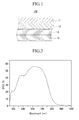
- FIG. 1 illustrates a cross-sectional view of a structure of a dye-sensitized solar cell 100 in accordance with an embodiment.
- the dye-sensitized solar cell 100 may have, e.g., a sandwich structure where two plate-type transparent electrodes, which may include a working electrode 11 and a counter electrode 14, respectively, facing each other.
- One side of one transparent electrode of the two transparent electrodes 11 and 14, e.g., the working electrode 11, may include a light absorption layer 12.
- the light absorption layer 12 may include a semiconductor particulate and the dye of an embodiment adsorbed on the semiconductor particulate. The electrons of the dye may be excited by absorbing light in the long wavelength region.
- a space between the two electrodes 11 and 14 may be filled with an electrolyte 13 for an oxidation-reduction reaction.
- dye molecules in the light absorption layer 12 may absorb photons.
- the dye molecules that have absorbed the photons may be excited from a ground state, to generate excitons (electron-hole pairs).
- the electrons may be injected into a conduction band of the semiconductor particulate.
- the injected electrons may be transferred from the light absorbing layer 12 to the working electrode 11 through the interface and then may be transferred to the counter electrode 14 through an external circuit.
- the dye that is oxidized as a result of the electron transfer may be reduced by an oxidation-reduction reaction in the electrolyte 13.
- the oxidized ions may be involved in a reduction reaction with electrons that have arrived at the interface of the counter electrode 14 to achieve charge neutrality.
- the dye sensitized solar cell 100 may be operated as described above.
- the working electrode 11 may include a transparent substrate and a conductive layer, e.g., a transparent conductive layer, on the transparent substrate.
- the transparent substrate may be, e.g., a plastic substrate or a glass substrate.
- the glass substrate and the plastic substrate may have thereon a layer formed using, e.g., indium tin oxide (ITO), fluorine tin oxide (FTO), ZnO-(Ga 2 O 3 or Al 2 O 3 ), tin oxide (SnO 2 ), and/or zinc oxide.
- ITO indium tin oxide
- FTO fluorine tin oxide
- tin oxide (SnO 2 ) tin oxide
- zinc oxide e.g., zinc oxide
- SnO 2 may be used because it has excellent conductivity, transparency, and heat resistance.
- ITO may be used because it has low production costs.
- the plastic substrate may include, e.g., polyethylene terephthalate (PET), polyethylene naphthalate (PEN), polycarbonate (PC), polypropylene (PP), polyimide (PI), and/or triacetylcellulose (TAC).
- PET polyethylene terephthalate
- PEN polyethylene naphthalate
- PC polycarbonate
- PP polypropylene
- PI polyimide
- TAC triacetylcellulose
- the working electrode 11 may be doped with a doping material including, e.g., Ti, In, Ga, and/or Al.
- the light absorption layer 12 may include a semiconductor particulate and the dye of an embodiment.
- the dye of an embodiment may be adsorbed on the semiconductor particulate, and the electrons of the dye may be excited by the absorption of light in long wavelength regions.
- the semiconductor particulate may include, e.g., silicon, metal oxide, and/or composite metal oxide having a perovskite structure.
- the semiconductor may be, e.g., an n-type semiconductor, in which electrons of the conduction band become a carrier by being optically excited and provide an anode current.
- the semiconductor particulate may include, e.g., Si, Ge, TiO 2 , SnO 2 , ZnO, WO 3 , Nb 2 O 5 , and/or TiSrO 3 .
- the TiO 2 may be anatase TiO 2 .
- the semiconductor particulate may have a large surface area to make the dye adsorbed onto the surface of the semiconductor particulate absorb more light.
- the semiconductor particulate may have an average particle diameter of, e.g., 50 nm or less. Maintaining the particle diameter at 50 nm or less may help ensure that a surface area ratio does not decrease and thereby decrease the light absorption amount of dye and deteriorate catalyst efficiency.
- the semiconductor particulate may have an average particle diameter of 15 nm to 25 nm.
- the light absorption layer 12 may further include at least one additive represented by Formula 4 in order to, e.g., improve photoelectric conversion efficiency of a solar cell.
- Formula 4 at least one additive represented by Formula 4 in order to, e.g., improve photoelectric conversion efficiency of a solar cell.
- Z may be hydrogen, a hydroxy, a halogen, a nitro, a cyano, a carboxyl, a substituted or unsubstituted amino, a substituted or unsubstituted acyl, a substituted or unsubstituted acyloxy, a substituted or unsubstituted alkyl, a substituted or unsubstituted cycloalkyl, a substituted or unsubstituted haloalkyl, a substituted or unsubstituted alkylsulfonyl, a substituted or unsubstituted arylsulfonyl, a substituted or unsubstituted alkylthio, a substituted or unsubstituted alkoxy, a substituted or unsubstituted alkoxysulfonyl, a substituted or unsubstituted alkoxycarbonyl, a substituted or unsubstituted
- the additive is deoxycholic acid represented by Formula 6, phenylpropionic acid, dodecylmalonic acid, or dodecylphosphonic acid.
- the additive may be included in an amount of 100 to 3,000 parts by weight, based on 100 parts by weight of the dye. Maintaining the amount of the additive at 100 to 3,000 parts by weight may help ensure that dye aggregation does not occur and the dye may be efficiently adsorbed on the semiconductor particulate. In an implementation, the additive may be included in an amount of 100 to 2,000 parts by weight, based on 100 parts by weight of the dye.
- the light absorption layer 12 may have a thickness of 25 ⁇ m or less. Maintaining the thickness of the light absorption layer 12 at 25 ⁇ m or less may help ensure that serial resistance is lowered and electron transport efficiency to the working electrode 11 is improved, resulting in improved photoelectric conversion efficiency of a resultant solar cell.
- the thickness may be 1 to 25 ⁇ m. In another implementation, the thickness may be 5 to 25 ⁇ m
- the counter electrode 14 may be formed of any suitable material that has a conductive property. Even if the material is an insulating material, if a conductive layer is formed on a side facing the working electrode 11, it may be used as the counter electrode 14.
- the counter electrode 14 may include, e.g., Pt, Au, Ni, Cu, Ag, In, Ru, Pd, Rh, Ir, Os, C, and/or a conductive polymer.
- the counter electrode 14 may be, e.g., a conductive layer including at least one of the above materials on a glass substrate or a plastic substrate.
- the glass substrate and the plastic substrate for the counter electrode 14 may have a conductive layer thereon including, e.g., indium tin oxide (ITO), fluorine tin oxide (FTO), ZnO-(Ga 2 O 3 or Al 2 O 3 ), tin oxide, and/or zinc oxide.
- a side of the counter electrode 14 facing the working electrode 11 may have a micro structure to increase the surface area.
- the term 'black state' refers to a state not supported by a supporter.
- platinum black may be formed by, e.g., performing anodic oxidation onto platinum or treating platinum with platinum chloride acid.
- the porous carbon may be formed by, e.g., sintering a carbon particulate or baking an organic polymer.
- the electrolyte 13 may include, e.g., an iodide/triiodide pair that receives and transports electrons from the counter electrode 14 to the dye through an oxidation-reduction reaction.
- An open circuit voltage may be determined by a difference between an energy potential of the dye and a redox potential of the electrolyte.
- the electrolyte 13 may be uniformly dispersed between the working electrode 11 and counter electrode 14.
- the electrolyte 13 may also be impregnated inside the light absorption layer 12.
- the electrolyte 13 may be a solution prepared by, e.g., dissolving iodine in acetonitrile.
- the electrolyte 13 may be any suitable substance having hole conductivity.
- the dye sensitized solar cell 100 may be fabricated by a method including, e.g., providing a first, i.e., working, electrode 11 including a conductive transparent substrate, forming a light absorption layer 12 including a semiconductor particulate and the dye of an embodiment on a side of the first electrode 11, fabricating a second, i.e., counter, electrode 14, arranging the first electrode 11 including the light absorption layer 12 and the second electrode 14 to face each other, filling an electrolyte 13 between the first electrode 11 and second electrode 14, and sealing the cell.
- a method including, e.g., providing a first, i.e., working, electrode 11 including a conductive transparent substrate, forming a light absorption layer 12 including a semiconductor particulate and the dye of an embodiment on a side of the first electrode 11, fabricating a second, i.e., counter, electrode 14, arranging the first electrode 11 including the light absorption layer 12 and the second electrode 14 to face each other, filling an electrolyte 13 between
- a conductive transparent substrate may be provided as the first electrode 11.
- a side of the conductive transparent substrate may be coated with a paste including a semiconductor particulate.
- a heat treatment may be performed to thereby form a porous semiconductor particulate layer on the transparent substrate.
- the properties of the paste may vary according to how the substrate is coated.
- the substrate may be coated with the paste using, e.g., a doctor blade or screen printing method.
- a transparent layer e.g., a spin-coating or spraying method, may be used.
- a general wet coating method may be used.
- a binder may be added to the paste.
- the heat treatment may be carried out at about 400 °C to about 600 °C for about 30 minutes. If no binder is added, the heat treatment may be performed at a temperature of less than about 200 °C.
- the porosity of the porous layer may be increased and maintained by adding a polymer to the porous semiconductor particulate layer and performing the heat treatment at about 400 °C to about 600 °C.
- the polymer may not leave organic material after the heat treatment.
- the polymer may include, e.g., ethylene cellulose (EC), hydroxy propyl cellulose (HPC), polyethylene glycol (PEG), polyethylene oxide (PEO), polyvinyl alcohol (PVA), and polyvinyl pyrrolidone (PVP).
- the polymer may have an appropriate molecular weight in consideration of the coating method and coating conditions. With an appropriate polymer added to the semiconductor particulate layer, a dispersion property as well as the porosity may be improved. Further, the layer may be better formed due to, e.g., an increased viscosity, and adhesiveness to the substrate may be improved.
- a dye layer may be formed by, e.g., spraying a dye dispersion onto the semiconductor particulate layer or coating or dipping the semiconductor particulate layer with or in the dye dispersion to adsorb the dye on the semiconductor particulate.
- the dye dispersion may further include an additive including, e.g., compounds represented by Formula 6, in order to improve photoelectric efficiency of a resultant solar cell.
- the additive may be included at a concentration of about 0.3 mM to about 60 mM in the dye dispersion.
- the additive may be included in an amount of about 100 to about 3000 parts by weight, based on 100 parts by weight of the dye in the light absorption layer 12.
- Maintaining the concentration of the additive at about 0.3 mM to about 60 mM in the dye dispersion may help ensure that dye aggregation does not occur and dye adsorption efficiency is improved.
- the additive may be included at a concentration of about 5 mM to about 40 mM in the dye dispersion.
- the dye may be naturally adsorbed on the semiconductor particulate when the first electrode 11 having the semiconductor particulate layer is dipped in the dye dispersion for, e.g., about 12 hours.
- the solvent dispersing the dye may be any suitable solvent including, e.g., acetonitrile, dichloromethane, and an alcohol-based solvent.
- the dye dispersion may further include, e.g., an organic colorant of a variety of colors to further improve the long-wavelength light absorption and to further improve the light absorption efficiency of the dye.
- the organic colorant may include, e.g., coumarin and pheophorbide A, which is a kind of porphyrin.
- preparation of the light absorption layer 12 may be completed by, e.g., washing out the dye that is not adsorbed through solvent washing.
- the second electrode 14 may be prepared by forming a conductive layer including a conductive material on a conductive transparent substrate using, e.g., electroplating, electron beam deposition, or a physical vapor deposition (PVD) method such as sputtering.
- PVD physical vapor deposition
- the first electrode 11 and the second electrode 14 may be arranged such that the light absorption layer 12 faces the second electrode 14. Then, a space between the light absorption layer 12 and the second electrode 14 may be filled with the electrolyte 13 and sealed to complete the dye-sensitized solar cell 10.
- the first electrode 11 and the second electrode 14 may be coupled to each other by using an adhesive agent.
- the adhesive agent may be, e.g., a thermoplastic polymer film, such as Surlyn produced by the DuPont Company.
- the thermoplastic polymer film may be placed between the two electrodes and heat and pressure may be applied to the electrodes.
- an epoxy resin or an ultraviolet (UV) ray curing material may be used as the adhesive agent.
- the adhesive agent may then be hardened after heat treatment or UV treatment.
- the dye (3) was synthesized according to Reaction Scheme 1.
- a mixed solvent of water (30 ml) and dichloromethane (50 ml) was added to the cooled mixed solution to extract an organic layer.
- the extracted organic layer was subjected to a first drying using magnesium sulfate (MgSO 4 ) and then a second drying under vacuum. Then, the compound (3c) was separated using a silica gel chromatography.
- a solution including the separated compound (3c), dioxane (2 ml), and hydrochloric acid (0.5 ml) was heated to 60 °C and then subjected to refluxing for 2 hours, agitating, and drying.
- a mixed solvent including water (30 ml) and dichloromethane (50 ml) was added the dried product to extract an organic layer.
- the extracted organic layer was subjected to a first drying using MgSO 4 and then a second drying under vacuum. Then, the compound (3d) was separated using a silica gel chromatography.
- the mixed solution was dried using a rotary evaporator under vacuum to obtain a dried product.
- a mixed solvent including water (30 ml) and dichloromethane (50 ml) was added the dried product to extract an organic layer.
- the extracted organic layer was subjected to a first drying using MgSO 4 and then a second drying under vacuum. Then, the compound (3) was separated using silica gel chromatography.
- Example 1 Fabrication of a dye-sensitized solar cell
- a titanium dioxide dispersion solution including titanium dioxide particles with a particle diameter of 5 to 15 nm was applied to 1 cm 2 of an indium-doped tin oxide transparent conductor using a doctor blade method.
- a heat treatment was performed at 450 °C for 30 minutes to form a 18 ⁇ m-thick porous titanium dioxide layer.
- a 0.3 mM dye dispersion solution was prepared by dissolving a compound represented by Chemical Formula 3 in ethanol, and then a resulting dye dispersion solution was prepared by adding deoxycholic acid to be 10 mM in the 0.3 mM dye dispersion solution.
- the 18 ⁇ m-thick porous titanium oxide layer was maintained at 80 °C and dipped in the resulting dye dispersion solution to adsorb the dye for over 12 hours.
- the dye-adsorbed porous titanium oxide layer was washed with ethanol and dried at room temperature to thereby form a first electrode with a light absorption layer thereon.
- a second electrode was prepared by depositing a 200 nm-thick Pt layer on an indium-doped tin oxide transparent conductor by sputtering. Then, a fine hole was formed therein with a drill having a diameter of 0.75 mm.
- thermoplastic polymer film was disposed between the first electrode and the second electrode and pressure was applied to the first and second electrodes at 100 °C for 9 seconds to adhere the two electrodes.
- An oxidation-reduction electrolyte was injected through the fine hole in the second electrode and the fine hole was sealed using a cover glass and a thermoplastic polymer film to thereby fabricate a dye-sensitized solar cell.
- the dye-sensitized solar cell was a 0.2 cm 2 cell, about 1 ml of the oxidation-reduction electrolyte was injected therein.
- the oxidation-reduction electrolyte was prepared by dissolving 1,2-dimethyl-3-hexylimidazolium iodide, 2-aminopyrimidine, LiI, and I 2 in an acetonitrile solvent.
- the concentration of the 1,2-dimethyl-3-hexylimidazolium iodide was 0.62 M
- that of the 2-aminopyrimidine was 0.5 M
- that of the LiI was 0.1 M
- that of the I 2 was 0.05 M.
- a titanium oxide dispersion solution including titanium oxide particles with an average particle diameter of 5 to 15 nm was applied to 1 cm 2 of an indium-doped tin oxide transparent conductor using a doctor blade method. Then, a heat treatment was performed at 450 °C for 30 minutes to thereby form a 18 ⁇ m-thick porous titanium oxide layer.
- a 0.3 mM dye dispersion solution was prepared by dissolving a compound represented by Chemical Formula 7 in ethanol, and then a resulting dye dispersion solution was prepared by adding deoxycholic acid to be 10 mM in the 0.3 mM dye dispersion solution.
- the 18 ⁇ m-thick porous titanium oxide layer was maintained at 80 °C and dipped in the resulting dye dispersion solution to adsorb the dye for over 12 hours.
- the dye-adsorbed porous titanium oxide layer was washed with ethanol and dried at room temperature to form a first electrode with a light absorption layer thereon.
- a second electrode was prepared by depositing a 200 nm-thick Pt layer on an indium-doped tin oxide transparent conductor by sputtering. Then, a fine hole was formed therein with a drill having a diameter of 0.75 mm.
- thermoplastic polymer film was disposed between the first electrode and the second electrode. Pressure was then applied to the first and second electrodes at 100 °C for 9 seconds to adhere the two electrodes. An oxidation-reduction electrolyte was injected through the fine hole in the second electrode. The fine hole was then sealed using a cover glass and a thermoplastic polymer film to thereby fabricate a dye-sensitized solar cell. When the dye-sensitized solar cell was 0.2 cm 2 cell, about 1 ml of the oxidation-reduction electrolyte was injected therein.
- the oxidation-reduction electrolyte was prepared by dissolving 1,2-dimethyl-3-hexylimidazolium iodide, 2-aminopyrimidine, LiI, and I 2 in an acetonitrile solvent.
- the concentration of the 1,2-dimethyl-3-hexylimidazolium iodide was 0.62 M
- that of the 2-aminopyrimidine was 0.5 M
- that of the LiI was 0.1 M
- that of the I 2 was 0.05 M.
- a dye-sensitized solar cell was fabricated according to the same method as in Comparative Example 1, except that a compound represented Chemical Formula 8 was used for the dye.
- Photocurrent voltages of the dye-sensitized solar cells according to Example 1 and Comparative Examples 1 and 2 were measured.
- the open-circuit voltage (Voc), current density (short-circuit current: Jsc), and a fill factor (FF) were calculated based on a curve line of the measured photocurrent voltages. From the results, solar cell efficiency was evaluated. The results are shown in Table 1.
- a xenon lamp (Oriel, 01193), was used as a light source, and the solar condition (AM 1.5) of the xenon lamp was corrected by using a standard solar cell (Fraunhofer Institut Solare Energysysteme, Certificate No. C-ISE369, Type of material: Mono-Si + KG filter).
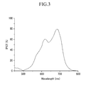
- IPCE Photoelectric conversion efficiency
- the dye-sensitized solar cell of Example 1 absorbed light in an infrared ray (IR) region as well as a visible ray region to efficiently convert light energy into electrical energy. Accordingly, the current density (short-circuit current, Jsc) of the dye-sensitized solar cell according to Example 1 was greater than those of the dye-sensitized solar cell of Comparative Examples 1 and 2.
- the overall photoelectric conversion efficiency of the dye-sensitized solar cell of Example 1 was greater than that of the dye-sensitized solar cell according to Comparative Example 1, and was equivalent to that of the dye-sensitized solar cell according to Comparative Example 2.
Abstract


Description
- The present invention relates to a dye for a dye-sensitized solar cell and a dye-sensitized solar cell including the same.
- Attempts have been made to develop energy sources that can replace fossil fuels. Extensive research is underway to find ways for using alternative energy sources, e.g., wind power, atomic power, and solar power, as substitutes for petroleum resources, which may be depleted within several decades. Among the alternative energy sources, solar cells use solar energy that is infinite and environmentally friendly, as opposed to other energy sources. Since 1983 when a Se solar cell was first produced, solar cells have been highlighted, and Si solar cells have recently been drawing attention.
- However, it may be difficult to practically use Si solar cells because production costs may be high. Therefore, a dye-sensitized solar cell that may be produced at a low cost has attracted attention.
- Embodiments are directed to a dye for a dye-sensitized solar cell and a dye-sensitized solar cell including the same, which substantially overcome one or more of the drawbacks, limitations, and/or disadvantages of the related art.
- It is a feature of an embodiment to provide a dye for a dye-sensitized solar cell having high efficiency.
- It is another feature of an embodiment to provide a dye-sensitized solar cell having improved short-circuit current and photoelectric conversion efficiency and being capable of suppressing dark currents.
- At least one of the above and other features and advantages is realized by providing a dye for a dye-sensitized solar cell represented by Formula 1, Formula 2, or a combination thereof:


- R1, R2, R13 and R14 may each independently be a substituted or unsubstituted C9 to C30 aromatic group, a substituted or unsubstituted C2 to C30 heterocyclic group, a substituted or unsubstituted C13 to C30 aliphatic group, or a substituted or unsubstituted C3 to C30 alicyclic group.
- At least one of R1, R2, R13 and R14 may be a substituted or unsubstituted fluorenyl group.
- R9 and R21 may each independently be a substituted or unsubstituted C5 to C15 aliphatic group.
- Y1 and Y2 may each independently be a carboxyl group, a sulfonic acid group, a phosphoric acid group, or a hydroxy group.
- The dye may be represented by Formula 3-1:

- The dye may be represented by Formula 3-2:

- At least one of the above and other features and advantages may also be realized by providing a dye-sensitized solar cell including a first electrode including a conductive transparent substrate, a light absorption layer on one side of the first electrode, a second electrode facing the one side of the first electrode, and an electrolyte between the first electrode and the second electrode, wherein the light absorption layer includes a semiconductor particulate and the dye for a dye-sensitized solar cell as shown above.
- The light absorption layer may further include at least one additive represented by Formula 4:
Z-COOH (4)
wherein Z is one of a hydrogen, a hydroxy, a halogen, a nitro, a cyano, a carboxyl, a substituted or unsubstituted amino, a substituted or unsubstituted acyl, a substituted or unsubstituted acyloxy, a substituted or unsubstituted alkyl, a substituted or unsubstituted cycloalkyl, a substituted or unsubstituted haloalkyl, a substituted or unsubstituted alkylsulfonyl, a substituted or unsubstituted arylsulfonyl, a substituted or unsubstituted alkylthio, a substituted or unsubstituted alkoxy, a substituted or unsubstituted alkoxysulfonyl, a substituted or unsubstituted alkoxycarbonyl, a substituted or unsubstituted aryl, a substituted or unsubstituted aryloxy, a substituted or unsubstituted alkenyl, a substituted or unsubstituted arylalkyl, or a substituted or unsubstituted heterocyclic group. - The additive may be one of deoxycholic acid, phenylpropionic acid, dodecylmalonic acid, and dodecylphosphonic acid.
- The additive may be included in an amount of 100 to 3,000 parts by weight, based on 100 parts by weight of the dye for a dye-sensitized solar cell.
- The light absorption layer may have a thickness of 25 µm or less.
- The above and other features and advantages will become more apparent to those of ordinary skill in the art by describing in detail exemplary embodiments with reference to the attached drawings, in which:
-
FIG. 1 illustrates a schematic view of a dye-sensitized solar cell according to an embodiment; -
FIG. 2 illustrates a graph showing incident photon-to-current efficiency (IPCE) according to wavelength for the dye-sensitized solar cell according to Example 1; -
FIG. 3 illustrates a graph showing incident photon-to-current efficiency (IPCE) according to wavelength for the dye-sensitized solar cell according to Comparative Example 1; and -
FIG. 4 illustrates a graph showing incident photon-to-current efficiency (IPCE) according to wavelength for the dye-sensitized solar cell according to Comparative Example 2. - Example embodiments will now be described more fully hereinafter with reference to the accompanying drawings.
- In the drawing figures, the dimensions of layers and regions may be exaggerated for clarity of illustration. It will also be understood that when a layer or element is referred to as being "on" another layer or substrate, it can be directly on the other layer or substrate, or intervening layers may also be present. Further, it will be understood that when a layer is referred to as being "under" another layer, it can be directly under, and one or more intervening layers may also be present. In addition, it will also be understood that when a layer is referred to as being "between" two layers, it can be the only layer between the two layers, or one or more intervening layers may also be present. Like reference numerals refer to like elements throughout. As used herein, the terms "a" and "an" are open terms that may be used in conjunction with singular items or with plural items.
- As used herein, when specific definition is not provided, the term "alkyl" refers to a C1 to C30 alkyl and, in an implementation, a C1 to C20 an alkyl. The term "cycloalkyl" refers to a C3 to C30 cycloalkyl and, in an implementation, a C3 to C20 cycloalkyl. The term "haloalkyl" refers to a C1 to C30 haloalkyl and, in an implementation, a C1 to C20 haloalkyl. The term "alkylsulfonyl" refers to a C1 to C30 alkylsulfonyl and, in an implementation, a C1 to C20 an alkylsulfonyl. The term "arylsulfonyl" refers to a C6 to C30 an arylsulfonyl and, in an implementation, a C6 to C20 arylsulfonyl. The term "an alkylthio" refers to a C1 to C30 alkylthio and, in an implementation, C1 to C20 an alkylthio. The term "alkoxy" refers to a C1 to C30 alkoxy and, in an implementation, a C1 to C20 alkoxy. The term "haloalkoxy" refers to a C1 to C30 haloalkoxy and, in an implementation, a C1 to C20 haloalkoxy. The term "alkoxysulfonyl" refers to a C1 to C30 alkoxysulfonyl and, in an implementation, a C1 to C20 alkoxysulfonyl. The term "alkoxycarbonyl" refers to a C2 to C30 alkoxycarbonyl and, in an implementation, a C2 to C20 alkoxycarbonyl. The term "acyl" refers to a C1 to C30 acyl and, in an implementation, a C1 to C20 acyl. The term "acyloxy" refers to a C1 to C30 acyloxy and, in an implementation, a C1 to C20 acyloxy. The term "aryl" refers to a C6 to C30 aryl and, in an implementation, a C6 to C20 aryl. The term "heteroaryl" refers to a C6 to C30 heteroaryl and, in an implementation, a C6 to C20 heteroaryl. The term "aryloxy" refers to a C6 to C30 aryloxy and, in an implementation, a C6 to C20 aryloxy. The term "alkenyl" refers to a C2 to C30 alkenyl and, in an implementation, a C2 to C20 alkenyl. The term "alkynyl" refers to a C2 to C30 alkynyl and, in an implementation, a C2 to C20 alkynyl. The term "arylalkyl" refers to a C6 to C30 arylalkyl and, in an implementation, a C6 to C20 arylalkyl. The term "heterocyclic group" refers to a C2 to C30 heterocyclic group and, in an implementation, a C2 to C20 heterocyclic group. The term "alkylene" refers to a C1 to C30 alkylene and, in an implementation, a C1 to C20 alkylene. The term "cycloalkylene" refers to a C3 to C30 cycloalkylene and, in an implementation, a C3 to C20 cycloalkylene. The term "alkenylene" refers to a C2 to C30 alkenylene and, in an implementation, a C2 to C20 alkenylene. The term "arylene" refers to a C6 to C30 arylene and, in an implementation, a C6 to C20 arylene.
- As used herein, when specific definition is not provided, the term "aliphatic group" refers to a C1 to C30 alkyl, a C2 to C30 alkenyl, or a C2 to C30 alkynyl. The term "alicyclic group" refers to a C3 to C30 cycloalkyl, a C3 to C30 cycloalkenyl, or a C3 to C30 cycloalkynyl. The term "aromatic group" refers to a C6 to C30 aryl.
- As used herein, when specific definition is not provided, the term "substituted" refers to one substituted with a substituent including at least one of hydroxy, a halogen, a nitro, a cyano, an amino, a carboxyl, a sulfonyl, an alkyl, a cycloalkyl, an alkoxy, a haloalkyl, a haloalkoxy, an acyl, an acyloxy, an alkylsulfonyl, an arylsulfonyl, an alkylthio, an alkoxysulfonyl, an alkoxycarbonyl, an aryl, an aryloxy, an alkenyl, an arylalkyl, and a heterocyclic group instead of hydrogen of a compound or a functional group. As used herein, when specific definition is not provided, the term "heterocyclic group" refers to a substituted or unsubstituted C2 to C30 cyclo alkyl, a substituted or unsubstituted C2 to C30 cycloalkenyl, a substituted or unsubstituted C2 to C30 cycloalkynyl, or a substituted or unsubstituted C2 to C30 heteroaryl that includes 1 to 3 heteroatoms including at least one of O, S, N, P, and Si in one ring.
- As used herein, the symbol "*" refers to a portion to be linked to the same or different atom or chemical formula.
- As used herein, when specific definition is not provided, the term "long wavelength region" refers to a range of wavelengths from a visible ray region to an infrared region, a wavelength region of about 400 nm to about 850 nm, or a wavelength region of about 550 nm to about 750 nm.
- A dye-sensitized solar cell is an electrochemical solar cell that includes photosensitive dye molecules, which absorb light and produce electron-hole pairs, and a transition metal oxide, which transfers the produced electrons. The dye sensitized solar cell may use nano titanium oxide, e.g., anatase titanium oxide, which was described by Michael Gratzel et al. of the Swiss Federal Institute of Technology, Lausanne (EPFL), Switzerland, in 1991. The dye sensitized solar cell may be produced at a low cost, and because it uses a transparent electrode, there may be an advantage in that it may be applied to external glass walls of a building or a glass greenhouse.
- During driving of a dye-sensitized solar cell, photocharges may be generated by optical energy. In general, the photocharges may be generated by dye materials. The dye materials may be excited by absorbing light transmitted through a conductive transparent substrate.
- For the dye materials, metal composites, e.g., a mono, bis, or tris(substituted 2,2'-bipyridine) complex salts of ruthenium have typically been used. However, such metal composites have a low efficiency because electrons excited by light may quickly return to a ground state. In order to increase efficiency, metal composites linked with various electron transporting materials through covalent bonds have been considered. However, linking the electron transporting materials through covalent bonds may require complicated processes.
- Typical dye sensitized solar cells may have a limitation in application for practical use due to low photoelectric conversion efficiency. Therefore, new technology that improves the photoelectric conversion efficiency, e.g., the dye sensitized solar cell of an embodiment, is desirable.
- According to an embodiment of the present invention, a compound for use as a dye for a dye-sensitized solar cell (hereinafter, "dye") includes a squaraine unit having a double bond at an end thereof. The compound also includes, linked to the end of the squaraine unit through the double bond, a functional group represented by Formula 5. According to a first alternative, the compound includes, linked to the end of the squaraine unit through the double bond, a substituted or unsubstituted benzofuran including a functional group linked to the ring oxygen (O). According to a second alternative, the compound includes, linked to the end of the squaraine unit through the double bond, a substituted or unsubstituted benzothiophene including a functional group linked to the ring sulfur (S).

- In Chemical Formula 5, R9 to R12 are each independently hydrogen, a substituted or unsubstituted aromatic group, a substituted or unsubstituted heterocyclic group, a substituted or unsubstituted aliphatic group, or a substituted or unsubstituted alicyclic group, Y1 is an acidic functional group or a hydroxy group, n4 is an integer of 1 to 4, n5 is an integer of 0 to 3, and the sum of n4+n5 is 4 or less. In an implementation, the sum of n4+n5 may be 4, 3, 2, or 1. In another implementation, n5 may be an integer of 1 to 3.
- The compound is applicable as a dye, and may thereby improve short-circuit current and photoelectric conversion efficiency of a dye-sensitized solar cell, in addition to suppressing dark current generation. As described above, the compound may also include, linked to the end of the squaraine unit through the double bond, a substituted or unsubstituted benzofuran including a functional group linked to the ring oxygen (O), or a substituted or unsubstituted benzothiophene including a functional group linked to the ring sulfur (S). The functional groups linked to the ring oxygen (O) or ring sulfur (S) include, a substituted or unsubstituted aromatic group, a substituted or unsubstituted heterocyclic group, a substituted or unsubstituted aliphatic group, and a substituted or unsubstituted alicyclic group.
- The dye is represented by Formula 1, Formula 2, or a combination thereof.


- In Formulae 1 and 2, R1 to R3, R9 to R12, R13 to R15, and R21 to R23 may each independently be hydrogen, a substituted or unsubstituted aromatic group, a substituted or unsubstituted heterocyclic group, substituted or unsubstituted aliphatic group, or a substituted or unsubstituted alicyclic group. In Formulae 1 and 2, R4 to R8 and R16 to R20 may each independently be hydrogen or a substituted or unsubstituted aliphatic group. In Formula 2, X may be oxygen (O) or sulfur (S). In Formulae 1 and 2, Y1 and Y2 may each independently be an acidic functional group or a hydroxy group. In Formulae 1 and 2, n1 and n6 may each independently be integers of 0 to 4, n2 and n7 may each independently be integers of 1 to 4, n3 and n8 may each independently be integers of 0 to 2, n4 and n9 may each independently be integers of 1 to 4, n5 and n10 may each independently be integers of 0 to 3, the sum of n4+n5 may be 4 or less, and the sum of n9+n10 may be 4 or less. In an implementation, the sum of n9+n10 may be 4, 3, 2, or 1. In another implementation, n1 and n6 may each independently be integers of 1 to 4. In yet another implementation, n5 and n10 may each independently be integers of 1 to 3.
- In an implementation, R1, R2, R13, and R14 may each independently be a substituted or unsubstituted C9 to C30 aromatic group, a substituted or unsubstituted C2 to C30 heterocyclic group, a substituted or unsubstituted C13 to C30 aliphatic group, or a substituted or unsubstituted C3 to C30 alicyclic group. In another implementation, R1, R2, R13, and R14 may each independently be a substituted or unsubstituted C9 to C20 aromatic group, a substituted or unsubstituted C2 to C20 heterocyclic group, a substituted or unsubstituted C13 to C20 aliphatic group, or a substituted or unsubstituted C3 to C20 alicyclic group.
- The aromatic group may include, e.g., phenyl, naphthyl, xylyl, anthryl, phenanthryl, naphthacenyl, pyrenyl, biphenylyl, terphenylyl, tolyl, fluorenyl, indenyl, perylenyl, and the like.
- The heterocyclic group may include, e.g., thiazolyl, benzothiazolyl, naphtothiazolyl, benzoxazolyl, naphtoxazolyl, imidazolyl, benzoimidazolyl, naphtoimidazolyl, thiazolyl, pyrrolyl, pyrazinyl, pyridyl, indolyl, isoindolyl, furyl, benzofuryl, isobenzofuryl, quinolyl, isoquinolyl, quinoxalinyl, carbazolyl, phenanthridinyl, acridinyl, phenanthrolinyl, phenazinyl, phenothiazinyl, phenoxazinyl, oxazolyl, oxadiazolyl, furazanyl, thienyl, and the like.
- In another implementation, at least one of R1, R2, R13, and R14 may be a substituted or unsubstituted fluorenyl group.
- In another implementation, at least one of R1 and R2 and at least one of R13 and R14 may be a substituted or unsubstituted fluorenyl group.
- R9 and R21 may each independently be a substituted or unsubstituted C1 to C15 alkyl. In an implementation, R9 and R21 may be octyl.
- Y1 and Y2 may each independently be a carboxyl group, a sulfonic acid group, a phosphoric acid group, or a hydroxy group.
- R4 to R8 and R16 to R20 may each independently be hydrogen or a substituted or unsubstituted C1 to C15 aliphatic group.
- In an implementation, the dye may be a compound represented by Formula 3-1.

- In Formula 3-1, R9 may be covalently bound to the ring nitrogen and may be, e.g., hydrogen, a substituted or unsubstituted aromatic group, a substituted or unsubstituted heterocyclic group, substituted or unsubstituted aliphatic group, or a substituted or unsubstituted alicyclic group. In an implemetation, R9 may be a linear alkyl group.
- In an implementation, the dye may be a compound represented by Formula 3-2.

- The dye includes an electron donor and electron acceptor linked to the squaraine unit. The squaraine unit acts as a strong electron transporter to lower a LUMO (lowest unoccupied molecular orbital) level of the compound, thereby enabling the dye to efficiently absorb light in a long wavelength region. The squaraine unit may include a hydroxyl (OH) to act as an auxiliary anchor for adsorbing onto semiconductor particulates.
- The dye includes an electron acceptor linked to the squaraine unit. The electron acceptor may include a functional group such as a functional group represented by Formula 5 having an acidic functional group or a hydroxyl group. In another implementation, the electron acceptor may include a functional group including a substituted or unsubstituted benzofuran having an acidic functional group or a hydroxyl group. In another implementation, the electron acceptor may include a functional group including a substituted or unsubstituted benzothiophene having an acidic functional group or a hydroxyl group. Thus, the dye may efficiently absorb a light in a long wavelength region. The acidic functional group or hydroxyl may act as an electron acceptor and anchor. The functional group linked to nitrogen (N) of the functional group represented by Formula 5, the functional group linked to oxygen (O) of the benzofuran, and the functional group linked to sulfur (S) of the benzothiophene should be hydrophobic and bulky to protect the nitrogen (N), oxygen (O), and sulfur (S) from attack of triiodide ions (I3 -), and thereby suppress dark current generation.
- In the dye, the electron donor, squaraine unit, and electron acceptor are linearly linked to each other. Thus, charge separation can be easily realized and charges can be present in an exited state for a long time, resulting in improved photoelectric conversion efficiency.
- Therefore, the dye according to an embodiment exhibits high efficiency when exposed to light of a long wavelength region.
- The dye may be applicable to various dye-sensitized solar cells. The dye is an easily purified organic compound and exhibits a high absorbance coefficient in a long wavelength region, as compared to a conventional dye. Accordingly, the dye of an embodiment is applicable to a thin film solar cell. The dye may be a transparent dye to absorb light in a long wavelength region including, e.g., an infrared region, to be applicable to a solar cell for buildings. The dye may be mixed with an organic dye to absorb a light in another wavelength region to be usable in a tandem solar cell. In this case, photoelectric conversion efficiency may be even more improved.
- The dye-sensitized solar cell is described with reference to
FIG. 1. FIG. 1 illustrates a cross-sectional view of a structure of a dye-sensitizedsolar cell 100 in accordance with an embodiment. - Referring to
FIG. 1 , the dye-sensitizedsolar cell 100 may have, e.g., a sandwich structure where two plate-type transparent electrodes, which may include a workingelectrode 11 and acounter electrode 14, respectively, facing each other. One side of one transparent electrode of the twotransparent electrodes electrode 11, may include alight absorption layer 12. Thelight absorption layer 12 may include a semiconductor particulate and the dye of an embodiment adsorbed on the semiconductor particulate. The electrons of the dye may be excited by absorbing light in the long wavelength region. A space between the twoelectrodes electrolyte 13 for an oxidation-reduction reaction. - When light enters the dye-sensitized
solar cell 100, dye molecules in thelight absorption layer 12 may absorb photons. The dye molecules that have absorbed the photons may be excited from a ground state, to generate excitons (electron-hole pairs). The electrons may be injected into a conduction band of the semiconductor particulate. The injected electrons may be transferred from thelight absorbing layer 12 to the workingelectrode 11 through the interface and then may be transferred to thecounter electrode 14 through an external circuit. The dye that is oxidized as a result of the electron transfer may be reduced by an oxidation-reduction reaction in theelectrolyte 13. The oxidized ions may be involved in a reduction reaction with electrons that have arrived at the interface of thecounter electrode 14 to achieve charge neutrality. The dye sensitizedsolar cell 100 may be operated as described above. - The working
electrode 11 may include a transparent substrate and a conductive layer, e.g., a transparent conductive layer, on the transparent substrate. The transparent substrate may be, e.g., a plastic substrate or a glass substrate. The glass substrate and the plastic substrate may have thereon a layer formed using, e.g., indium tin oxide (ITO), fluorine tin oxide (FTO), ZnO-(Ga2O3 or Al2O3), tin oxide (SnO2), and/or zinc oxide. In an implementation, SnO2 may be used because it has excellent conductivity, transparency, and heat resistance. In another implementation, ITO may be used because it has low production costs. The plastic substrate may include, e.g., polyethylene terephthalate (PET), polyethylene naphthalate (PEN), polycarbonate (PC), polypropylene (PP), polyimide (PI), and/or triacetylcellulose (TAC). The workingelectrode 11 may be doped with a doping material including, e.g., Ti, In, Ga, and/or Al. - The
light absorption layer 12 may include a semiconductor particulate and the dye of an embodiment. The dye of an embodiment may be adsorbed on the semiconductor particulate, and the electrons of the dye may be excited by the absorption of light in long wavelength regions. - The semiconductor particulate may include, e.g., silicon, metal oxide, and/or composite metal oxide having a perovskite structure. The semiconductor may be, e.g., an n-type semiconductor, in which electrons of the conduction band become a carrier by being optically excited and provide an anode current. In particular, the semiconductor particulate may include, e.g., Si, Ge, TiO2, SnO2, ZnO, WO3, Nb2O5, and/or TiSrO3. The TiO2 may be anatase TiO2.
- The semiconductor particulate may have a large surface area to make the dye adsorbed onto the surface of the semiconductor particulate absorb more light. The semiconductor particulate may have an average particle diameter of, e.g., 50 nm or less. Maintaining the particle diameter at 50 nm or less may help ensure that a surface area ratio does not decrease and thereby decrease the light absorption amount of dye and deteriorate catalyst efficiency. In an implementation, the semiconductor particulate may have an average particle diameter of 15 nm to 25 nm.
- The
light absorption layer 12 may further include at least one additive represented by Formula 4 in order to, e.g., improve photoelectric conversion efficiency of a solar cell.
Z-COOH (4)
- In Formula 4, Z may be hydrogen, a hydroxy, a halogen, a nitro, a cyano, a carboxyl, a substituted or unsubstituted amino, a substituted or unsubstituted acyl, a substituted or unsubstituted acyloxy, a substituted or unsubstituted alkyl, a substituted or unsubstituted cycloalkyl, a substituted or unsubstituted haloalkyl, a substituted or unsubstituted alkylsulfonyl, a substituted or unsubstituted arylsulfonyl, a substituted or unsubstituted alkylthio, a substituted or unsubstituted alkoxy, a substituted or unsubstituted alkoxysulfonyl, a substituted or unsubstituted alkoxycarbonyl, a substituted or unsubstituted aryl, a substituted or unsubstituted aryloxy, a substituted or unsubstituted alkenyl, a substituted or unsubstituted arylalkyl, or a substituted or unsubstituted heterocyclic group.
- In an implementation, the additive is deoxycholic acid represented by Formula 6, phenylpropionic acid, dodecylmalonic acid, or dodecylphosphonic acid.

- The additive may be included in an amount of 100 to 3,000 parts by weight, based on 100 parts by weight of the dye. Maintaining the amount of the additive at 100 to 3,000 parts by weight may help ensure that dye aggregation does not occur and the dye may be efficiently adsorbed on the semiconductor particulate. In an implementation, the additive may be included in an amount of 100 to 2,000 parts by weight, based on 100 parts by weight of the dye.
- The
light absorption layer 12 may have a thickness of 25 µm or less. Maintaining the thickness of thelight absorption layer 12 at 25 µm or less may help ensure that serial resistance is lowered and electron transport efficiency to the workingelectrode 11 is improved, resulting in improved photoelectric conversion efficiency of a resultant solar cell. In an implementation, the thickness may be 1 to 25 µm. In another implementation, the thickness may be 5 to 25 µm - The
counter electrode 14 may be formed of any suitable material that has a conductive property. Even if the material is an insulating material, if a conductive layer is formed on a side facing the workingelectrode 11, it may be used as thecounter electrode 14. Thecounter electrode 14 may include, e.g., Pt, Au, Ni, Cu, Ag, In, Ru, Pd, Rh, Ir, Os, C, and/or a conductive polymer. - The
counter electrode 14 may be, e.g., a conductive layer including at least one of the above materials on a glass substrate or a plastic substrate. In another implementation, the glass substrate and the plastic substrate for thecounter electrode 14 may have a conductive layer thereon including, e.g., indium tin oxide (ITO), fluorine tin oxide (FTO), ZnO-(Ga2O3 or Al2O3), tin oxide, and/or zinc oxide. - In order to improve redox catalyst efficiency, a side of the
counter electrode 14 facing the workingelectrode 11 may have a micro structure to increase the surface area. For example, it may be desirable to form Pt or Au in a black state and to form carbon in a porous structure. Herein, the term 'black state' refers to a state not supported by a supporter. Particularly, platinum black may be formed by, e.g., performing anodic oxidation onto platinum or treating platinum with platinum chloride acid. The porous carbon may be formed by, e.g., sintering a carbon particulate or baking an organic polymer. - The
electrolyte 13 may include, e.g., an iodide/triiodide pair that receives and transports electrons from thecounter electrode 14 to the dye through an oxidation-reduction reaction. An open circuit voltage may be determined by a difference between an energy potential of the dye and a redox potential of the electrolyte. Theelectrolyte 13 may be uniformly dispersed between the workingelectrode 11 andcounter electrode 14. Theelectrolyte 13 may also be impregnated inside thelight absorption layer 12. - The
electrolyte 13 may be a solution prepared by, e.g., dissolving iodine in acetonitrile. Alternatively, theelectrolyte 13 may be any suitable substance having hole conductivity. - The dye sensitized
solar cell 100 according to an embodiment may be fabricated by a method including, e.g., providing a first, i.e., working,electrode 11 including a conductive transparent substrate, forming alight absorption layer 12 including a semiconductor particulate and the dye of an embodiment on a side of thefirst electrode 11, fabricating a second, i.e., counter,electrode 14, arranging thefirst electrode 11 including thelight absorption layer 12 and thesecond electrode 14 to face each other, filling anelectrolyte 13 between thefirst electrode 11 andsecond electrode 14, and sealing the cell. - Hereinafter a process of forming the
light absorption layer 12 is described in detail. - First, a conductive transparent substrate may be provided as the
first electrode 11. A side of the conductive transparent substrate may be coated with a paste including a semiconductor particulate. Then, a heat treatment may be performed to thereby form a porous semiconductor particulate layer on the transparent substrate. - The properties of the paste may vary according to how the substrate is coated. The substrate may be coated with the paste using, e.g., a doctor blade or screen printing method. To form a transparent layer, e.g., a spin-coating or spraying method, may be used. Alternatively, a general wet coating method may be used. A binder may be added to the paste. The heat treatment may be carried out at about 400 °C to about 600 °C for about 30 minutes. If no binder is added, the heat treatment may be performed at a temperature of less than about 200 °C.
- The porosity of the porous layer may be increased and maintained by adding a polymer to the porous semiconductor particulate layer and performing the heat treatment at about 400 °C to about 600 °C. The polymer may not leave organic material after the heat treatment. The polymer may include, e.g., ethylene cellulose (EC), hydroxy propyl cellulose (HPC), polyethylene glycol (PEG), polyethylene oxide (PEO), polyvinyl alcohol (PVA), and polyvinyl pyrrolidone (PVP). The polymer may have an appropriate molecular weight in consideration of the coating method and coating conditions. With an appropriate polymer added to the semiconductor particulate layer, a dispersion property as well as the porosity may be improved. Further, the layer may be better formed due to, e.g., an increased viscosity, and adhesiveness to the substrate may be improved.
- A dye layer may be formed by, e.g., spraying a dye dispersion onto the semiconductor particulate layer or coating or dipping the semiconductor particulate layer with or in the dye dispersion to adsorb the dye on the semiconductor particulate. The dye dispersion may further include an additive including, e.g., compounds represented by Formula 6, in order to improve photoelectric efficiency of a resultant solar cell. The additive may be included at a concentration of about 0.3 mM to about 60 mM in the dye dispersion. The additive may be included in an amount of about 100 to about 3000 parts by weight, based on 100 parts by weight of the dye in the
light absorption layer 12. Maintaining the concentration of the additive at about 0.3 mM to about 60 mM in the dye dispersion may help ensure that dye aggregation does not occur and dye adsorption efficiency is improved. In an implementation, the additive may be included at a concentration of about 5 mM to about 40 mM in the dye dispersion. - The dye may be naturally adsorbed on the semiconductor particulate when the
first electrode 11 having the semiconductor particulate layer is dipped in the dye dispersion for, e.g., about 12 hours. The solvent dispersing the dye may be any suitable solvent including, e.g., acetonitrile, dichloromethane, and an alcohol-based solvent. - The dye dispersion may further include, e.g., an organic colorant of a variety of colors to further improve the long-wavelength light absorption and to further improve the light absorption efficiency of the dye. The organic colorant may include, e.g., coumarin and pheophorbide A, which is a kind of porphyrin.
- After the dye layer is formed, preparation of the
light absorption layer 12 may be completed by, e.g., washing out the dye that is not adsorbed through solvent washing. - The
second electrode 14 may be prepared by forming a conductive layer including a conductive material on a conductive transparent substrate using, e.g., electroplating, electron beam deposition, or a physical vapor deposition (PVD) method such as sputtering. - The
first electrode 11 and thesecond electrode 14 may be arranged such that thelight absorption layer 12 faces thesecond electrode 14. Then, a space between thelight absorption layer 12 and thesecond electrode 14 may be filled with theelectrolyte 13 and sealed to complete the dye-sensitizedsolar cell 10. - The
first electrode 11 and thesecond electrode 14 may be coupled to each other by using an adhesive agent. The adhesive agent may be, e.g., a thermoplastic polymer film, such as Surlyn produced by the DuPont Company. The thermoplastic polymer film may be placed between the two electrodes and heat and pressure may be applied to the electrodes. Alternatively, an epoxy resin or an ultraviolet (UV) ray curing material may be used as the adhesive agent. The adhesive agent may then be hardened after heat treatment or UV treatment. - The following examples illustrate the embodiments in more detail.
- The dye (3) was synthesized according to Reaction Scheme 1.


- Referring to Reaction Scheme 1, a synthesis process of the dye (3) is described. First, a mixed solution including 4-(bis(9,9-dimethyl-9H-fluoren-2-yl)amino)benzaldehyde (3b) (1.91 g, 3.77 mmol), 3-isopropoxy-4-methylcyclobut-3-ene-1,2-dione (3a) (0.58 g, 3.77 mmol), triethylamine (NEt3, 0.554 ml, 3.95 mmol), and acetic anhydride (Ac2O) (0.369 ml 3.95 mmol) was refluxed for 8 hours and agitated. Then, the mixed solution was cooled to room temperature. A mixed solvent of water (30 ml) and dichloromethane (50 ml) was added to the cooled mixed solution to extract an organic layer. The extracted organic layer was subjected to a first drying using magnesium sulfate (MgSO4) and then a second drying under vacuum. Then, the compound (3c) was separated using a silica gel chromatography.
- A solution including the separated compound (3c), dioxane (2 ml), and hydrochloric acid (0.5 ml) was heated to 60 °C and then subjected to refluxing for 2 hours, agitating, and drying. A mixed solvent including water (30 ml) and dichloromethane (50 ml) was added the dried product to extract an organic layer. The extracted organic layer was subjected to a first drying using MgSO4 and then a second drying under vacuum. Then, the compound (3d) was separated using a silica gel chromatography.
- The compound (3d) (0.2 g, 0.316 mmol), and 5-carboxy-2,3,3-trimethyl-1-octyl-3H-indolium iodide (3e) (0.143 g, 0.316 mmol were dissolved in benzene (40 ml) and n-butanol (30 ml), followed by refluxing for 24 hours and agitating to prepare a mixed solution.
- The mixed solution was dried using a rotary evaporator under vacuum to obtain a dried product. A mixed solvent including water (30 ml) and dichloromethane (50 ml) was added the dried product to extract an organic layer. The extracted organic layer was subjected to a first drying using MgSO4 and then a second drying under vacuum. Then, the compound (3) was separated using silica gel chromatography.
- A titanium dioxide dispersion solution including titanium dioxide particles with a particle diameter of 5 to 15 nm was applied to 1 cm2 of an indium-doped tin oxide transparent conductor using a doctor blade method. A heat treatment was performed at 450 °C for 30 minutes to form a 18 µm-thick porous titanium dioxide layer. A 0.3 mM dye dispersion solution was prepared by dissolving a compound represented by Chemical Formula 3 in ethanol, and then a resulting dye dispersion solution was prepared by adding deoxycholic acid to be 10 mM in the 0.3 mM dye dispersion solution. The 18 µm-thick porous titanium oxide layer was maintained at 80 °C and dipped in the resulting dye dispersion solution to adsorb the dye for over 12 hours.
- The dye-adsorbed porous titanium oxide layer was washed with ethanol and dried at room temperature to thereby form a first electrode with a light absorption layer thereon.
- A second electrode was prepared by depositing a 200 nm-thick Pt layer on an indium-doped tin oxide transparent conductor by sputtering. Then, a fine hole was formed therein with a drill having a diameter of 0.75 mm.
- A 60 µm-thick thermoplastic polymer film was disposed between the first electrode and the second electrode and pressure was applied to the first and second electrodes at 100 °C for 9 seconds to adhere the two electrodes. An oxidation-reduction electrolyte was injected through the fine hole in the second electrode and the fine hole was sealed using a cover glass and a thermoplastic polymer film to thereby fabricate a dye-sensitized solar cell. When the dye-sensitized solar cell was a 0.2 cm2 cell, about 1 ml of the oxidation-reduction electrolyte was injected therein. The oxidation-reduction electrolyte was prepared by dissolving 1,2-dimethyl-3-hexylimidazolium iodide, 2-aminopyrimidine, LiI, and I2 in an acetonitrile solvent. In the prepared oxidation-reduction electrolyte, the concentration of the 1,2-dimethyl-3-hexylimidazolium iodide was 0.62 M, that of the 2-aminopyrimidine was 0.5 M, that of the LiI was 0.1 M, and that of the I2 was 0.05 M.
- A titanium oxide dispersion solution including titanium oxide particles with an average particle diameter of 5 to 15 nm was applied to 1 cm2 of an indium-doped tin oxide transparent conductor using a doctor blade method. Then, a heat treatment was performed at 450 °C for 30 minutes to thereby form a 18 µm-thick porous titanium oxide layer. A 0.3 mM dye dispersion solution was prepared by dissolving a compound represented by Chemical Formula 7 in ethanol, and then a resulting dye dispersion solution was prepared by adding deoxycholic acid to be 10 mM in the 0.3 mM dye dispersion solution. The 18 µm-thick porous titanium oxide layer was maintained at 80 °C and dipped in the resulting dye dispersion solution to adsorb the dye for over 12 hours.

- The dye-adsorbed porous titanium oxide layer was washed with ethanol and dried at room temperature to form a first electrode with a light absorption layer thereon.
- A second electrode was prepared by depositing a 200 nm-thick Pt layer on an indium-doped tin oxide transparent conductor by sputtering. Then, a fine hole was formed therein with a drill having a diameter of 0.75 mm.
- A 60 µm-thick thermoplastic polymer film was disposed between the first electrode and the second electrode. Pressure was then applied to the first and second electrodes at 100 °C for 9 seconds to adhere the two electrodes. An oxidation-reduction electrolyte was injected through the fine hole in the second electrode. The fine hole was then sealed using a cover glass and a thermoplastic polymer film to thereby fabricate a dye-sensitized solar cell. When the dye-sensitized solar cell was 0.2 cm2 cell, about 1 ml of the oxidation-reduction electrolyte was injected therein. The oxidation-reduction electrolyte was prepared by dissolving 1,2-dimethyl-3-hexylimidazolium iodide, 2-aminopyrimidine, LiI, and I2 in an acetonitrile solvent. In the prepared oxidation-reduction electrolyte, the concentration of the 1,2-dimethyl-3-hexylimidazolium iodide was 0.62 M, that of the 2-aminopyrimidine was 0.5 M, that of the LiI was 0.1 M, and that of the I2 was 0.05 M.
- A dye-sensitized solar cell was fabricated according to the same method as in Comparative Example 1, except that a compound represented Chemical Formula 8 was used for the dye.

- Photocurrent voltages of the dye-sensitized solar cells according to Example 1 and Comparative Examples 1 and 2 were measured. The open-circuit voltage (Voc), current density (short-circuit current: Jsc), and a fill factor (FF) were calculated based on a curve line of the measured photocurrent voltages. From the results, solar cell efficiency was evaluated. The results are shown in Table 1.
- A xenon lamp (Oriel, 01193), was used as a light source, and the solar condition (AM 1.5) of the xenon lamp was corrected by using a standard solar cell (Fraunhofer Institut Solare Energiesysteme, Certificate No. C-ISE369, Type of material: Mono-Si + KG filter).
- Photoelectric conversion efficiency (IPCE, incident photon to current efficiency) of the dye-sensitized solar cells according to Example 1, Comparative Example 1, and Comparative Example 2 were measured. Herein, the IPCE was evaluated by measuring intensity of photoelectric conversion values of the dye-sensitized solar cell at each wavelength region using SR-810 (PV measurements Inc.). The photoelectric conversion efficiency measurement results are illustrated in
FIGS. 2 ,3 , and4 .Table 1 Example 1 Comparative Example 1 Comparative Example 2 Voc (V) 0.493 0.617 0.603 Jsc (mA/cm2) 12.54 7.60 10.50 FF 70 75 71 Efficiency (%) 4.33 3.52 4.5 - As shown in Table 1, current density (short-circuit current, Jsc) of the dye-sensitized solar cell of Example 1 was greater than those of the dye-sensitized solar cells according to Comparative Examples 1 and 2. As illustrated in
FIGS. 2 to 4 , the dye-sensitized solar cell of Example 1 absorbed light in a long wavelength region of about 400 nm to about 800 nm. On the contrary, the dye-sensitized solar cell of Comparative Example 1 absorbed light in a wavelength region of only about 600 nm to about 700 nm. The dye-sensitized solar cell of Comparative Example 2 absorbed light in a wavelength region of only about 550 nm to about 700 nm. - Therefore, the dye-sensitized solar cell of Example 1 absorbed light in an infrared ray (IR) region as well as a visible ray region to efficiently convert light energy into electrical energy. Accordingly, the current density (short-circuit current, Jsc) of the dye-sensitized solar cell according to Example 1 was greater than those of the dye-sensitized solar cell of Comparative Examples 1 and 2.
- Also, as shown in Table 1, the overall photoelectric conversion efficiency of the dye-sensitized solar cell of Example 1 was greater than that of the dye-sensitized solar cell according to Comparative Example 1, and was equivalent to that of the dye-sensitized solar cell according to Comparative Example 2.
Claims (12)
- A dye for a dye-sensitized solar cell represented by Formula 1, Formula 2, or a combination thereof:

 R1 to R3, R9 to R12, R13 to R15, and R21 to R23 are each independently hydrogen, a substituted or unsubstituted aromatic group, a substituted or unsubstituted heterocyclic group, substituted or unsubstituted aliphatic group, or a substituted or unsubstituted alicyclic group,R4 to R8 and R16 to R20 are each independently hydrogen or a substituted or unsubstituted aliphatic group,X is O or S,Y1 and Y2 are each independently an acidic functional group or a hydroxy group,n1 and n6 are each independently integers of 0 to 4,n2 and n7 are each independently integers of 1 to 4,n3 and n8 are each independently integers of 0 to 2,n4 and n9 are each independently integers of 1 to 4,n5 and n10 are each independently integers of 0 to 3,n4+n5 is an integer of 4 or less, andn9+n10 is an integer of 4 or less.
 - The dye of claim 1, wherein R1, R2, R13 and R14 are each independently a substituted or unsubstituted C9 to C30 aromatic group, a substituted or unsubstituted C2 to C30 heterocyclic group, a substituted or unsubstituted C13 to C30 aliphatic group, or a substituted or unsubstituted C3 to C30 alicyclic group.
- The dye of claim 2, wherein at least one of R1, R2, R13 and R14 is a substituted or unsubstituted fluorenyl group.
- The dye of any one of the preceding claims, wherein R9 and R21 are each independently a substituted or unsubstituted C5 to C15 aliphatic group.
- The dye of any one of the preceding claims, wherein Y1 and Y2 are each independently a carboxyl group, a sulfonic acid group, a phosphoric acid group, or a hydroxy group.
- The dye of claim 1 or claim 4, wherein the dye is represented by Formula 3-1:

- The dye of claim 6, wherein the dye is represented by Formula 3-2:

- A dye-sensitized solar cell, comprising:a first electrode including a conductive transparent substrate;a light absorption layer on one side of the first electrode;a second electrode facing the one side of the first electrode; andan electrolyte between the first electrode and the second electrode,wherein the light absorption layer includes a semiconductor particulate and the dye according to any one of claims 1 through 7.
- The dye-sensitized solar cell of claim 8, wherein the light absorption layer further includes at least one additive represented by Formula 4:
Z-COOH (4)
wherein Z is one of a hydrogen, a hydroxy, a halogen, a nitro, a cyano, a carboxyl, a substituted or unsubstituted amino, a substituted or unsubstituted acyl, a substituted or unsubstituted acyloxy, a substituted or unsubstituted alkyl, a substituted or unsubstituted cycloalkyl, a substituted or unsubstituted haloalkyl, a substituted or unsubstituted alkylsulfonyl, a substituted or unsubstituted arylsulfonyl, a substituted or unsubstituted alkylthio, a substituted or unsubstituted alkoxy, a substituted or unsubstituted alkoxysulfonyl, a substituted or unsubstituted alkoxycarbonyl, a substituted or unsubstituted aryl, a substituted or unsubstituted aryloxy, a substituted or unsubstituted alkenyl, a substituted or unsubstituted arylalkyl, or a substituted or unsubstituted heterocyclic group. - The dye-sensitized solar cell of claim 9, wherein the additive is one of deoxycholic acid, phenylpropionic acid, dodecylmalonic acid, and dodecylphosphonic acid.
- The dye-sensitized solar cell of claim 9 or 10, wherein the additive is included in an amount of 100 to 3,000 parts by weight, based on 100 parts by weight of the dye for a dye-sensitized solar cell.
- The dye-sensitized solar cell of any one of claims 8 through 11, wherein the light absorption layer has a thickness of 25 µm or less.
Applications Claiming Priority (1)
| Application Number | Priority Date | Filing Date | Title |
|---|---|---|---|
| KR1020090063233A KR101107069B1 (en) | 2009-07-10 | 2009-07-10 | Dye for dye-sensitized solar cell and dye-sensitized solar cell prepared using the same |
Publications (2)
| Publication Number | Publication Date |
|---|---|
| EP2272920A1 true EP2272920A1 (en) | 2011-01-12 |
| EP2272920B1 EP2272920B1 (en) | 2011-08-03 |
Family
ID=42235217
Family Applications (1)
| Application Number | Title | Priority Date | Filing Date |
|---|---|---|---|
| EP10162203A Not-in-force EP2272920B1 (en) | 2009-07-10 | 2010-05-06 | Dye for dye-sensitized solar cell and dye-sensitized solar cell including the same |
Country Status (6)
| Country | Link |
|---|---|
| US (1) | US20110005596A1 (en) |
| EP (1) | EP2272920B1 (en) |
| JP (1) | JP5122605B2 (en) |
| KR (1) | KR101107069B1 (en) |
| CN (1) | CN101950674B (en) |
| AT (1) | ATE518919T1 (en) |
Families Citing this family (7)
| Publication number | Priority date | Publication date | Assignee | Title |
|---|---|---|---|---|
| JP2012159975A (en) | 2011-01-31 | 2012-08-23 | Sony Corp | Information processor, method, and program |
| CN102532932B (en) * | 2012-01-12 | 2014-01-08 | 复旦大学 | Pyrazine-ring-containing organic dyes and preparation method and use thereof |
| US9865823B2 (en) * | 2012-03-30 | 2018-01-09 | Basf Se | Quinolinium dyes with fluorinated counter anion for dye sensitized solar cells |
| CN103972393B (en) * | 2013-02-06 | 2016-12-28 | 阮伸 | A kind of miniature natural organic membrane electrooptical device |
| US9911935B2 (en) * | 2015-09-04 | 2018-03-06 | International Business Machines Corporation | Transparent conducting oxide as top-electrode in perovskite solar cell by non-sputtering process |
| KR102564324B1 (en) | 2018-10-15 | 2023-08-07 | 삼성전자주식회사 | Apparatus of semiconductor memory and method of manufacturing the same |
| CN113140682A (en) * | 2021-04-10 | 2021-07-20 | 中国计量大学 | PVP/PVA modified perovskite solar cell based on ZnO @ ZnSe nanorod array and preparation method thereof |
Citations (2)
| Publication number | Priority date | Publication date | Assignee | Title |
|---|---|---|---|---|
| JP2006265549A (en) * | 2005-02-28 | 2006-10-05 | Sumitomo Chemical Co Ltd | Pigment compound, and photoelectric transducer and photoelectrochemical cell using the compound |
| JP2008177147A (en) * | 2006-12-20 | 2008-07-31 | Gifu Univ | Sensitizing dye used for dye-sensitized photoelectric conversion element and solar cell using sensitizing dye |
Family Cites Families (15)
| Publication number | Priority date | Publication date | Assignee | Title |
|---|---|---|---|---|
| US4806488A (en) * | 1985-09-06 | 1989-02-21 | Syntex (U.S.A.) Inc. | Ligand-receptor assays employing squarate dye compositions |
| US6852920B2 (en) * | 2002-06-22 | 2005-02-08 | Nanosolar, Inc. | Nano-architected/assembled solar electricity cell |
| KR101065308B1 (en) * | 2004-02-04 | 2011-09-16 | 삼성에스디아이 주식회사 | Photoelectrochemical cell |
| KR101042959B1 (en) * | 2004-06-03 | 2011-06-20 | 삼성에스디아이 주식회사 | Solar cell and manufacturing method thereof |
| US7868157B2 (en) * | 2005-07-07 | 2011-01-11 | Biosearch Technologies, Inc. | Water soluble fluorescent compounds |
| KR100696636B1 (en) * | 2005-08-18 | 2007-03-19 | 삼성에스디아이 주식회사 | Photosensitizer for photovoltaic cell and photovoltaic cell prepared from the same |
| KR100786865B1 (en) * | 2005-12-26 | 2007-12-20 | 삼성에스디아이 주식회사 | Photovoltaic device |
| AU2007221706B2 (en) * | 2006-03-02 | 2011-12-22 | Nippon Kayaku Kabushiki Kaisha | Dye-sensitized photoelectric conversion device |
| KR100908721B1 (en) * | 2007-03-12 | 2009-07-22 | 삼성에스디아이 주식회사 | Dyes for dye-sensitized solar cells and dye-sensitized solar cells prepared therefrom |
| US8653279B2 (en) * | 2006-04-17 | 2014-02-18 | Samsung Sdi Co., Ltd. | Dye for dye-sensitized solar cell, and solar cell prepared from same |
| KR101223558B1 (en) * | 2006-04-17 | 2013-01-17 | 삼성에스디아이 주식회사 | Photosensitizer for photovoltaic cell, and photovoltaic cell prepared from same |
| US8440840B2 (en) * | 2007-10-25 | 2013-05-14 | Sony Corporation | Dye including an anchoring group in its molecular structure |
| KR100918049B1 (en) * | 2007-11-28 | 2009-09-18 | 삼성에스디아이 주식회사 | Photosensitizer for photovoltaic cell, and photovoltaic cell including same |
| US20100065112A1 (en) * | 2008-09-15 | 2010-03-18 | Thompson Mark E | Organic Photosensitive Devices Comprising a Squaraine Containing Organoheterojunction and Methods of Making Same |
| KR20110107185A (en) * | 2010-03-24 | 2011-09-30 | 삼성에스디아이 주식회사 | Spirobifluorene-based compound and dye sensitized fuel cell using the same |
-
2009
- 2009-07-10 KR KR1020090063233A patent/KR101107069B1/en not_active IP Right Cessation
-
2010
- 2010-04-06 US US12/662,204 patent/US20110005596A1/en not_active Abandoned
- 2010-04-30 JP JP2010105282A patent/JP5122605B2/en not_active Expired - Fee Related
- 2010-05-06 AT AT10162203T patent/ATE518919T1/en not_active IP Right Cessation
- 2010-05-06 EP EP10162203A patent/EP2272920B1/en not_active Not-in-force
- 2010-06-08 CN CN201010198672XA patent/CN101950674B/en not_active Expired - Fee Related
Patent Citations (2)
| Publication number | Priority date | Publication date | Assignee | Title |
|---|---|---|---|---|
| JP2006265549A (en) * | 2005-02-28 | 2006-10-05 | Sumitomo Chemical Co Ltd | Pigment compound, and photoelectric transducer and photoelectrochemical cell using the compound |
| JP2008177147A (en) * | 2006-12-20 | 2008-07-31 | Gifu Univ | Sensitizing dye used for dye-sensitized photoelectric conversion element and solar cell using sensitizing dye |
Non-Patent Citations (4)
| Title |
|---|
| H.QIN ET AL.: "An Organic Sensitizer with a fused Dithienothiophene Unit for efficient an stable Dye-Sensitized Solar Cells", J.AM.CHEM.SOC., vol. 130, 2008, pages 9202 - 9203, XP002588181 * |
| S.ALEX ET AL.: "Dye sensitization of nanocrystalline TiO2: enhanced efficiency of unsymmetrical versus symmetrical Squaraine Dyes", J.PHOTOCHEM.PHOTOBIOL.A, vol. 172, 2005, pages 63 - 71, XP002588180 * |
| SAYAMA K ET AL: "Efficient sensitization of nanocrystalline TiO2 films with cyanine and merocyanine organic dyes", SOLAR ENERGY MATERIALS AND SOLAR CELLS, ELSEVIER SCIENCE PUBLISHERS, AMSTERDAM, NL LNKD- DOI:10.1016/S0927-0248(03)00113-2, vol. 80, no. 1, 15 October 2003 (2003-10-15), pages 47 - 71, XP004456743, ISSN: 0927-0248 * |
| Y.CHEN ET AL.: "Highly efficient co-sensitization of nanocrystalline TiO2 Electrodes with plural Organic Dyes", NEW J.CHEM., vol. 29, 2005, pages 773 - 776, XP002588182 * |
Also Published As
| Publication number | Publication date |
|---|---|
| CN101950674A (en) | 2011-01-19 |
| KR20110005596A (en) | 2011-01-18 |
| US20110005596A1 (en) | 2011-01-13 |
| ATE518919T1 (en) | 2011-08-15 |
| KR101107069B1 (en) | 2012-01-20 |
| CN101950674B (en) | 2013-03-13 |
| EP2272920B1 (en) | 2011-08-03 |
| JP5122605B2 (en) | 2013-01-16 |
| JP2011018633A (en) | 2011-01-27 |
Similar Documents
| Publication | Publication Date | Title |
|---|---|---|
| KR101223558B1 (en) | Photosensitizer for photovoltaic cell, and photovoltaic cell prepared from same | |
| EP2508570B1 (en) | Organic metal dye, and photoelectric element and dye-sensitized solar cell using the organic metal dye | |
| KR100918049B1 (en) | Photosensitizer for photovoltaic cell, and photovoltaic cell including same | |
| Wang et al. | Exploitation of ionic liquid electrolyte for dye-sensitized solar cells by molecular modification of organic-dye sensitizers | |
| Puckyte et al. | Carbazole-based molecular glasses for efficient solid-state dye-sensitized solar cells | |
| EP2272920B1 (en) | Dye for dye-sensitized solar cell and dye-sensitized solar cell including the same | |
| JP5836375B2 (en) | Dye-sensitized solar cell with improved stability | |
| JP2007053102A (en) | Dye for dye-sensitized solar cell and dye-sensitized solar cell | |
| EP1780827A1 (en) | Semiconductor electrode, fabrication method thereof and solar cell comprising the same | |
| JP4563697B2 (en) | Dye-sensitized solar cell and method for producing the same | |
| KR101244210B1 (en) | Dye sensitized solar cell using ion bonding oligomer complexes and preparation method thereof | |
| KR101429759B1 (en) | Electrolyte composition comprising energy relay dyes for dye-sensitized solar cell and dye-sensitized solar cell comprising said electrolyte composition | |
| EP2372734A2 (en) | Ruthenium complex and dye-sensitized fuel cell using the same | |
| EP2246916A2 (en) | Amine dye for a dye sensitized solar cell | |
| JP2010100850A (en) | Ruthenium complex and photoelectric component using the same | |
| KR101551074B1 (en) | Solid-state dye-sensitized solar cell with long-term stability containing pyridine compound as an adhesive | |
| JP5233318B2 (en) | Photoelectric conversion element and solar cell | |
| KR101267658B1 (en) | Dye for dye-sensitized solarcell, preparation method of the same and dye-sensitized solar cell comprising the same | |
| JP2014186995A (en) | Transparent dye-sensitized solar cell and dye-sensitized solar cell module | |
| KR20080018238A (en) | Coumarin-containing dyes for dye-sensitized solar cells | |
| JP2010282780A (en) | Photoelectric conversion element and solar cell | |
| KR20080019669A (en) | Phenothiazine-containing dyes for dye-sensitized solar cells | |
| WO2018047494A1 (en) | Photoelectric conversion element, dye-sensitized solar cell and dipyrromethene complex compound | |
| KR101940491B1 (en) | A NOBLE Ru-TYPE SENSITIZERS AND METHOD FOR PREPARING OF IT | |
| JP5158761B2 (en) | Dye-sensitized semiconductor electrode and photoelectric conversion device using the same |
Legal Events
| Date | Code | Title | Description |
|---|---|---|---|
| PUAI | Public reference made under article 153(3) epc to a published international application that has entered the european phase |
Free format text: ORIGINAL CODE: 0009012 |
|
| 17P | Request for examination filed |
Effective date: 20100506 |
|
| AK | Designated contracting states |
Kind code of ref document: A1 Designated state(s): AL AT BE BG CH CY CZ DE DK EE ES FI FR GB GR HR HU IE IS IT LI LT LU LV MC MK MT NL NO PL PT RO SE SI SK SM TR |
|
| AX | Request for extension of the european patent |
Extension state: BA ME RS |
|
| GRAP | Despatch of communication of intention to grant a patent |
Free format text: ORIGINAL CODE: EPIDOSNIGR1 |
|
| RIC1 | Information provided on ipc code assigned before grant |
Ipc: C09B 57/00 20060101AFI20110214BHEP Ipc: H01G 9/20 20060101ALI20110214BHEP |
|
| GRAS | Grant fee paid |
Free format text: ORIGINAL CODE: EPIDOSNIGR3 |
|
| GRAA | (expected) grant |
Free format text: ORIGINAL CODE: 0009210 |
|
| AK | Designated contracting states |
Kind code of ref document: B1 Designated state(s): AL AT BE BG CH CY CZ DE DK EE ES FI FR GB GR HR HU IE IS IT LI LT LU LV MC MK MT NL NO PL PT RO SE SI SK SM TR |
|
| REG | Reference to a national code |
Ref country code: GB Ref legal event code: FG4D |
|
| REG | Reference to a national code |
Ref country code: CH Ref legal event code: EP |
|
| REG | Reference to a national code |
Ref country code: IE Ref legal event code: FG4D |
|
| REG | Reference to a national code |
Ref country code: DE Ref legal event code: R096 Ref document number: 602010000129 Country of ref document: DE Effective date: 20111013 |
|
| REG | Reference to a national code |
Ref country code: NL Ref legal event code: VDEP Effective date: 20110803 |
|
| LTIE | Lt: invalidation of european patent or patent extension |
Effective date: 20110803 |
|
| PG25 | Lapsed in a contracting state [announced via postgrant information from national office to epo] |
Ref country code: IS Free format text: LAPSE BECAUSE OF FAILURE TO SUBMIT A TRANSLATION OF THE DESCRIPTION OR TO PAY THE FEE WITHIN THE PRESCRIBED TIME-LIMIT Effective date: 20111203 Ref country code: FI Free format text: LAPSE BECAUSE OF FAILURE TO SUBMIT A TRANSLATION OF THE DESCRIPTION OR TO PAY THE FEE WITHIN THE PRESCRIBED TIME-LIMIT Effective date: 20110803 Ref country code: SE Free format text: LAPSE BECAUSE OF FAILURE TO SUBMIT A TRANSLATION OF THE DESCRIPTION OR TO PAY THE FEE WITHIN THE PRESCRIBED TIME-LIMIT Effective date: 20110803 Ref country code: HR Free format text: LAPSE BECAUSE OF FAILURE TO SUBMIT A TRANSLATION OF THE DESCRIPTION OR TO PAY THE FEE WITHIN THE PRESCRIBED TIME-LIMIT Effective date: 20110803 Ref country code: NO Free format text: LAPSE BECAUSE OF FAILURE TO SUBMIT A TRANSLATION OF THE DESCRIPTION OR TO PAY THE FEE WITHIN THE PRESCRIBED TIME-LIMIT Effective date: 20111103 Ref country code: NL Free format text: LAPSE BECAUSE OF FAILURE TO SUBMIT A TRANSLATION OF THE DESCRIPTION OR TO PAY THE FEE WITHIN THE PRESCRIBED TIME-LIMIT Effective date: 20110803 Ref country code: LT Free format text: LAPSE BECAUSE OF FAILURE TO SUBMIT A TRANSLATION OF THE DESCRIPTION OR TO PAY THE FEE WITHIN THE PRESCRIBED TIME-LIMIT Effective date: 20110803 Ref country code: PT Free format text: LAPSE BECAUSE OF FAILURE TO SUBMIT A TRANSLATION OF THE DESCRIPTION OR TO PAY THE FEE WITHIN THE PRESCRIBED TIME-LIMIT Effective date: 20111205 |
|
| REG | Reference to a national code |
Ref country code: AT Ref legal event code: MK05 Ref document number: 518919 Country of ref document: AT Kind code of ref document: T Effective date: 20110803 |
|
| PG25 | Lapsed in a contracting state [announced via postgrant information from national office to epo] |
Ref country code: GR Free format text: LAPSE BECAUSE OF FAILURE TO SUBMIT A TRANSLATION OF THE DESCRIPTION OR TO PAY THE FEE WITHIN THE PRESCRIBED TIME-LIMIT Effective date: 20111104 Ref country code: PL Free format text: LAPSE BECAUSE OF FAILURE TO SUBMIT A TRANSLATION OF THE DESCRIPTION OR TO PAY THE FEE WITHIN THE PRESCRIBED TIME-LIMIT Effective date: 20110803 Ref country code: LV Free format text: LAPSE BECAUSE OF FAILURE TO SUBMIT A TRANSLATION OF THE DESCRIPTION OR TO PAY THE FEE WITHIN THE PRESCRIBED TIME-LIMIT Effective date: 20110803 Ref country code: CY Free format text: LAPSE BECAUSE OF FAILURE TO SUBMIT A TRANSLATION OF THE DESCRIPTION OR TO PAY THE FEE WITHIN THE PRESCRIBED TIME-LIMIT Effective date: 20110803 Ref country code: AT Free format text: LAPSE BECAUSE OF FAILURE TO SUBMIT A TRANSLATION OF THE DESCRIPTION OR TO PAY THE FEE WITHIN THE PRESCRIBED TIME-LIMIT Effective date: 20110803 Ref country code: SI Free format text: LAPSE BECAUSE OF FAILURE TO SUBMIT A TRANSLATION OF THE DESCRIPTION OR TO PAY THE FEE WITHIN THE PRESCRIBED TIME-LIMIT Effective date: 20110803 |
|
| PG25 | Lapsed in a contracting state [announced via postgrant information from national office to epo] |
Ref country code: BE Free format text: LAPSE BECAUSE OF FAILURE TO SUBMIT A TRANSLATION OF THE DESCRIPTION OR TO PAY THE FEE WITHIN THE PRESCRIBED TIME-LIMIT Effective date: 20110803 |
|
| PG25 | Lapsed in a contracting state [announced via postgrant information from national office to epo] |
Ref country code: SK Free format text: LAPSE BECAUSE OF FAILURE TO SUBMIT A TRANSLATION OF THE DESCRIPTION OR TO PAY THE FEE WITHIN THE PRESCRIBED TIME-LIMIT Effective date: 20110803 Ref country code: CZ Free format text: LAPSE BECAUSE OF FAILURE TO SUBMIT A TRANSLATION OF THE DESCRIPTION OR TO PAY THE FEE WITHIN THE PRESCRIBED TIME-LIMIT Effective date: 20110803 |
|
| PG25 | Lapsed in a contracting state [announced via postgrant information from national office to epo] |
Ref country code: RO Free format text: LAPSE BECAUSE OF FAILURE TO SUBMIT A TRANSLATION OF THE DESCRIPTION OR TO PAY THE FEE WITHIN THE PRESCRIBED TIME-LIMIT Effective date: 20110803 Ref country code: IT Free format text: LAPSE BECAUSE OF FAILURE TO SUBMIT A TRANSLATION OF THE DESCRIPTION OR TO PAY THE FEE WITHIN THE PRESCRIBED TIME-LIMIT Effective date: 20110803 Ref country code: EE Free format text: LAPSE BECAUSE OF FAILURE TO SUBMIT A TRANSLATION OF THE DESCRIPTION OR TO PAY THE FEE WITHIN THE PRESCRIBED TIME-LIMIT Effective date: 20110803 |
|
| PLBE | No opposition filed within time limit |
Free format text: ORIGINAL CODE: 0009261 |
|
| STAA | Information on the status of an ep patent application or granted ep patent |
Free format text: STATUS: NO OPPOSITION FILED WITHIN TIME LIMIT |
|
| PG25 | Lapsed in a contracting state [announced via postgrant information from national office to epo] |
Ref country code: DK Free format text: LAPSE BECAUSE OF FAILURE TO SUBMIT A TRANSLATION OF THE DESCRIPTION OR TO PAY THE FEE WITHIN THE PRESCRIBED TIME-LIMIT Effective date: 20110803 |
|
| 26N | No opposition filed |
Effective date: 20120504 |
|
| REG | Reference to a national code |
Ref country code: DE Ref legal event code: R097 Ref document number: 602010000129 Country of ref document: DE Effective date: 20120504 |
|
| PG25 | Lapsed in a contracting state [announced via postgrant information from national office to epo] |
Ref country code: MC Free format text: LAPSE BECAUSE OF NON-PAYMENT OF DUE FEES Effective date: 20120531 |
|
| REG | Reference to a national code |
Ref country code: IE Ref legal event code: MM4A |
|
| PG25 | Lapsed in a contracting state [announced via postgrant information from national office to epo] |
Ref country code: MK Free format text: LAPSE BECAUSE OF FAILURE TO SUBMIT A TRANSLATION OF THE DESCRIPTION OR TO PAY THE FEE WITHIN THE PRESCRIBED TIME-LIMIT Effective date: 20110803 |
|
| PG25 | Lapsed in a contracting state [announced via postgrant information from national office to epo] |
Ref country code: IE Free format text: LAPSE BECAUSE OF NON-PAYMENT OF DUE FEES Effective date: 20120506 Ref country code: ES Free format text: LAPSE BECAUSE OF FAILURE TO SUBMIT A TRANSLATION OF THE DESCRIPTION OR TO PAY THE FEE WITHIN THE PRESCRIBED TIME-LIMIT Effective date: 20111114 |
|
| PG25 | Lapsed in a contracting state [announced via postgrant information from national office to epo] |
Ref country code: BG Free format text: LAPSE BECAUSE OF FAILURE TO SUBMIT A TRANSLATION OF THE DESCRIPTION OR TO PAY THE FEE WITHIN THE PRESCRIBED TIME-LIMIT Effective date: 20111103 |
|
| PG25 | Lapsed in a contracting state [announced via postgrant information from national office to epo] |
Ref country code: MT Free format text: LAPSE BECAUSE OF FAILURE TO SUBMIT A TRANSLATION OF THE DESCRIPTION OR TO PAY THE FEE WITHIN THE PRESCRIBED TIME-LIMIT Effective date: 20110803 |
|
| PG25 | Lapsed in a contracting state [announced via postgrant information from national office to epo] |
Ref country code: AL Free format text: LAPSE BECAUSE OF FAILURE TO SUBMIT A TRANSLATION OF THE DESCRIPTION OR TO PAY THE FEE WITHIN THE PRESCRIBED TIME-LIMIT Effective date: 20110803 |
|
| PG25 | Lapsed in a contracting state [announced via postgrant information from national office to epo] |
Ref country code: TR Free format text: LAPSE BECAUSE OF FAILURE TO SUBMIT A TRANSLATION OF THE DESCRIPTION OR TO PAY THE FEE WITHIN THE PRESCRIBED TIME-LIMIT Effective date: 20110803 |
|
| PG25 | Lapsed in a contracting state [announced via postgrant information from national office to epo] |
Ref country code: LU Free format text: LAPSE BECAUSE OF NON-PAYMENT OF DUE FEES Effective date: 20120506 Ref country code: SM Free format text: LAPSE BECAUSE OF FAILURE TO SUBMIT A TRANSLATION OF THE DESCRIPTION OR TO PAY THE FEE WITHIN THE PRESCRIBED TIME-LIMIT Effective date: 20110803 |
|
| PG25 | Lapsed in a contracting state [announced via postgrant information from national office to epo] |
Ref country code: HU Free format text: LAPSE BECAUSE OF FAILURE TO SUBMIT A TRANSLATION OF THE DESCRIPTION OR TO PAY THE FEE WITHIN THE PRESCRIBED TIME-LIMIT Effective date: 20100506 |
|
| PGFP | Annual fee paid to national office [announced via postgrant information from national office to epo] |
Ref country code: FR Payment date: 20140327 Year of fee payment: 5 Ref country code: GB Payment date: 20140326 Year of fee payment: 5 Ref country code: DE Payment date: 20140327 Year of fee payment: 5 |
|
| REG | Reference to a national code |
Ref country code: CH Ref legal event code: PL |
|
| PG25 | Lapsed in a contracting state [announced via postgrant information from national office to epo] |
Ref country code: LI Free format text: LAPSE BECAUSE OF NON-PAYMENT OF DUE FEES Effective date: 20140531 Ref country code: CH Free format text: LAPSE BECAUSE OF NON-PAYMENT OF DUE FEES Effective date: 20140531 |
|
| REG | Reference to a national code |
Ref country code: DE Ref legal event code: R119 Ref document number: 602010000129 Country of ref document: DE |
|
| GBPC | Gb: european patent ceased through non-payment of renewal fee |
Effective date: 20150506 |
|
| REG | Reference to a national code |
Ref country code: FR Ref legal event code: ST Effective date: 20160129 |
|
| PG25 | Lapsed in a contracting state [announced via postgrant information from national office to epo] |
Ref country code: GB Free format text: LAPSE BECAUSE OF NON-PAYMENT OF DUE FEES Effective date: 20150506 Ref country code: DE Free format text: LAPSE BECAUSE OF NON-PAYMENT OF DUE FEES Effective date: 20151201 |
|
| PG25 | Lapsed in a contracting state [announced via postgrant information from national office to epo] |
Ref country code: FR Free format text: LAPSE BECAUSE OF NON-PAYMENT OF DUE FEES Effective date: 20150601 |