WO2018047494A1 - Photoelectric conversion element, dye-sensitized solar cell and dipyrromethene complex compound - Google Patents
Photoelectric conversion element, dye-sensitized solar cell and dipyrromethene complex compound Download PDFInfo
- Publication number
- WO2018047494A1 WO2018047494A1 PCT/JP2017/026967 JP2017026967W WO2018047494A1 WO 2018047494 A1 WO2018047494 A1 WO 2018047494A1 JP 2017026967 W JP2017026967 W JP 2017026967W WO 2018047494 A1 WO2018047494 A1 WO 2018047494A1
- Authority
- WO
- WIPO (PCT)
- Prior art keywords
- group
- photoelectric conversion
- dye
- conversion element
- formula
- Prior art date
Links
Images


Classifications
-
- C—CHEMISTRY; METALLURGY
- C07—ORGANIC CHEMISTRY
- C07F—ACYCLIC, CARBOCYCLIC OR HETEROCYCLIC COMPOUNDS CONTAINING ELEMENTS OTHER THAN CARBON, HYDROGEN, HALOGEN, OXYGEN, NITROGEN, SULFUR, SELENIUM OR TELLURIUM
- C07F5/00—Compounds containing elements of Groups 3 or 13 of the Periodic System
- C07F5/02—Boron compounds
-
- C—CHEMISTRY; METALLURGY
- C09—DYES; PAINTS; POLISHES; NATURAL RESINS; ADHESIVES; COMPOSITIONS NOT OTHERWISE PROVIDED FOR; APPLICATIONS OF MATERIALS NOT OTHERWISE PROVIDED FOR
- C09B—ORGANIC DYES OR CLOSELY-RELATED COMPOUNDS FOR PRODUCING DYES, e.g. PIGMENTS; MORDANTS; LAKES
- C09B23/00—Methine or polymethine dyes, e.g. cyanine dyes
-
- H—ELECTRICITY
- H01—ELECTRIC ELEMENTS
- H01G—CAPACITORS; CAPACITORS, RECTIFIERS, DETECTORS, SWITCHING DEVICES OR LIGHT-SENSITIVE DEVICES, OF THE ELECTROLYTIC TYPE
- H01G9/00—Electrolytic capacitors, rectifiers, detectors, switching devices, light-sensitive or temperature-sensitive devices; Processes of their manufacture
- H01G9/20—Light-sensitive devices
-
- Y—GENERAL TAGGING OF NEW TECHNOLOGICAL DEVELOPMENTS; GENERAL TAGGING OF CROSS-SECTIONAL TECHNOLOGIES SPANNING OVER SEVERAL SECTIONS OF THE IPC; TECHNICAL SUBJECTS COVERED BY FORMER USPC CROSS-REFERENCE ART COLLECTIONS [XRACs] AND DIGESTS
- Y02—TECHNOLOGIES OR APPLICATIONS FOR MITIGATION OR ADAPTATION AGAINST CLIMATE CHANGE
- Y02E—REDUCTION OF GREENHOUSE GAS [GHG] EMISSIONS, RELATED TO ENERGY GENERATION, TRANSMISSION OR DISTRIBUTION
- Y02E10/00—Energy generation through renewable energy sources
- Y02E10/50—Photovoltaic [PV] energy
- Y02E10/542—Dye sensitized solar cells
Definitions
- the present invention relates to a photoelectric conversion element, a dye-sensitized solar cell, and a dipyrromethene complex compound.
- Photoelectric conversion elements are used in various photosensors, photocopiers, photoelectrochemical cells such as solar cells, and the like.
- Various methods such as a method using a metal, a method using a semiconductor, a method using an organic pigment or a dye, or a combination of these methods have been put to practical use for this photoelectric conversion element.
- a solar cell using non-depleting solar energy does not require fuel, and full-scale practical use is highly expected as it uses inexhaustible clean energy.
- silicon-based solar cells have been researched and developed for a long time, and are spreading due to national policy considerations.
- silicon is an inorganic material, there is a limit to improving throughput and cost.
- Patent Document 1 proposes a dye-sensitized solar cell using a boron complex compound having a 2-thienyl-5-carboxythiazole skeleton as a sensitizing dye.
- Non-Patent Document 1 proposes a dye-sensitized solar cell using, as a sensitizing dye, a dipyrromethene complex compound in which a boron atom is bonded to a dipyrromethene skeleton formed by bonding two pyrrole rings with a methine group.
- a dipyrromethene complex compound in which a boron atom is bonded to a dipyrromethene skeleton formed by bonding two pyrrole rings with a methine group.
- a triarylamino group was introduced via the ethenylene group at the 3rd and 5th positions of the dipyrromethene skeleton (the ring carbon atom adjacent to the ring nitrogen atom of each pyrrole ring). It is a complex compound.
- Patent Document 1 describes that by using the boron complex compound as a sensitizing dye of a dye-sensitized solar cell, improvement in photoelectric conversion efficiency can be expected. Further, in Non-Patent Document 1, it is possible to improve the short circuit current density and the conversion efficiency (overall conversion efficiency) by using the dipyrromethene complex compound as a sensitizing dye of a dye-sensitized solar cell. Are listed.
- An object of the present invention is to provide a photoelectric conversion element and a dye-sensitized solar cell exhibiting excellent photoelectric conversion efficiency, and a dipyrromethene complex compound suitably used for these.
- the inventors of the present invention have provided a photoelectric conversion element using a dipyrromethene complex compound in which an acidic group is introduced at positions 3 and 5 of the dipyrromethene skeleton, and more preferably a substituent is introduced at positions 2 and 6 of the skeleton as a sensitizing dye, and It was found that when used in a dye-sensitized solar cell, a high external quantum yield (IPCE) was exhibited even in a long wavelength region of 800 nm or more, and excellent photoelectric conversion efficiency could be exhibited.
- IPCE external quantum yield
- X represents CR 5 or N.
- R 5 represents an alkyl group, an alkenyl group, an alkynyl group, an aryl group or a heteroaryl group.
- R 1 to R 4 each independently represents an alkyl group, an alkenyl group, an alkynyl group, an aryl group, an alkoxy group, an alkylthio group, a heteroaryl group, an amino group, or a halogen atom.
- L 1 and L 2 each independently represent a single bond or a linking group.
- Z 1 and Z 2 each independently represent an acidic group or a salt thereof, and m and n each independently represents an integer of 1 or more.
- Y 1 and Y 2 each independently represent a halogen atom, an alkynyl group, an aryl group, a heteroaryl group, an alkoxy group, an aryloxy group, a heteroaryloxy group, an alkylthio group, an arylthio group or a heteroarylthio group.
- Each of L 1 and L 2 is an aliphatic unsaturated hydrocarbon group, an aromatic hydrocarbon ring group or an aromatic heterocyclic group, or an aliphatic unsaturated hydrocarbon group, an aromatic hydrocarbon ring group
- the photoelectric conversion element according to ⁇ 1> which represents a linking group formed by combining two or more groups selected from the group consisting of an aromatic heterocyclic group.
- L 1 and L 2 are each a combination of two or more groups selected from the group consisting of an aliphatic unsaturated hydrocarbon group, an aromatic hydrocarbon ring group, and an aromatic heterocyclic group
- L 1 and L 2 are both a linking group formed by combining two or more groups selected from the group consisting of an alkenylene group, an alkynylene group, an aromatic hydrocarbon ring group, and an aromatic heterocyclic group.
- L L1 represents a group represented by any of the following formulas (L-1) to (L-4).
- Ar L represents an aromatic hydrocarbon ring group or an aromatic heterocyclic group. * Represents a bond to the pyrrole ring in formula (1), and *** represents a bond to Z 1 or Z 2 in formula (1).
- R 21 to R 28 each independently represent a hydrogen atom or a substituent, and A represents an oxygen atom or a sulfur atom. * Represents a bond to the pyrrole ring in formula (1), and ** represents a bond to Ar L.
- ⁇ 7> The photoelectric conversion element according to any one of ⁇ 1> to ⁇ 6>, wherein L 1 and L 2 are both styryl groups.
- ⁇ 8> The photoelectric conversion element according to any one of ⁇ 1> to ⁇ 7>, wherein m and n are all 1.
- Each of Z 1 and Z 2 is an acidic group selected from —COOH, —SO 3 H, —PO (OH) 2 , —OH and —SH or a salt thereof ⁇ 1> to ⁇ 8> ⁇ 10>
- a dye-sensitized solar cell comprising the photoelectric conversion element according to any one of ⁇ 1> to ⁇ 9> above.
- a dipyrromethene complex compound represented by the following formula (1) represented by the following formula (1).
- X represents CR 5 or N.
- R 5 represents an alkyl group, an alkenyl group, an alkynyl group, an aryl group or a heteroaryl group.
- R 1 to R 4 each independently represents an alkyl group, an alkenyl group, an alkynyl group, an aryl group, an alkoxy group, an alkylthio group, a heteroaryl group, an amino group, or a halogen atom.
- L 1 and L 2 each independently represent a single bond or a linking group.
- Z 1 and Z 2 each independently represent an acidic group or a salt thereof, and m and n each independently represents an integer of 1 or more.
- Y 1 and Y 2 each independently represent a halogen atom, an alkynyl group, an aryl group, a heteroaryl group, an alkoxy group, an aryloxy group, a heteroaryloxy group, an alkylthio group, an arylthio group or a heteroarylthio group.
- the double bond may be either E-type or Z-type in the molecule, or a mixture thereof.
- substituents linking groups, ligands, etc. (hereinafter referred to as substituents, etc.) indicated by a specific symbol or formula, or when a plurality of substituents etc. are specified simultaneously, there is no special notice.
- substituents linking groups, ligands, etc.
- substituents etc.
- each substituent it may be the same or different.
- the definition of the number of substituents and the like when a plurality of substituents and the like are adjacent (particularly adjacent), they may be connected to each other to form a ring unless otherwise specified.
- a ring such as an alicyclic ring, an aromatic ring, or a heterocyclic ring may be further condensed to form a condensed ring.
- the display of a compound is used to mean not only the compound itself but also its salt and its ion. Moreover, it is the meaning including what changed a part of structure in the range which does not impair the effect of this invention. Furthermore, it is the meaning which may have arbitrary substituents in the range which does not impair the effect of this invention about the compound which does not specify substitution or unsubstituted. The same applies to substituents, linking groups and ligands.
- a numerical range represented by using “to” means a range including numerical values described before and after “to” as a lower limit value and an upper limit value.
- the photoelectric conversion element and the dye-sensitized solar cell of the present invention show excellent photoelectric conversion efficiency by supporting the dipyrromethene complex compound represented by the formula (1). Moreover, the dipyrromethene complex compound of this invention can raise the photoelectric conversion efficiency of a photoelectric conversion element and a dye-sensitized solar cell by using as a sensitizing dye.
- FIG. 1 is a cross-sectional view schematically showing an enlarged view of a circular portion in a layer in a system in which the photoelectric conversion element according to the first aspect of the present invention is applied to a battery.
- FIG. 2 is a cross-sectional view schematically showing a dye-sensitized solar cell including the photoelectric conversion element according to the second aspect of the present invention.
- FIG. 3 shows action spectra in a dye-sensitized solar cell (sample number 1) using the dipyrromethene complex compound D-1 and a dye-sensitized solar cell (sample number c1) using the dye compound C1 for comparison.
- FIG. 1 is a cross-sectional view schematically showing an enlarged view of a circular portion in a layer in a system in which the photoelectric conversion element according to the first aspect of the present invention is applied to a battery.
- FIG. 2 is a cross-sectional view schematically showing a dye-sensitized solar cell including the photoelectric conversion
- the photoelectric conversion element of the present invention has a conductive support, a photoreceptor layer containing an electrolyte, a charge transfer body layer containing an electrolyte, and a counter electrode (counter electrode).
- the photosensitive layer, the charge transfer layer, and the counter electrode are provided on the conductive support in this order.
- the semiconductor fine particles forming the photoreceptor layer are also referred to as a dipyrromethene complex compound represented by the following formula (1) as a sensitizing dye (also referred to as a dipyrromethene complex dye when used as a sensitizing dye).
- a sensitizing dye also referred to as a dipyrromethene complex dye when used as a sensitizing dye.
- the aspect in which the dipyrromethene complex dye is supported on the surface of the semiconductor fine particle includes an aspect in which the dipyrromethene complex dye is adsorbed on the surface of the semiconductor fine particle, an aspect in which the dipyrromethene complex dye is deposited on the surface of the semiconductor fine particle To do.
- the adsorption includes chemical adsorption and physical adsorption, and chemical adsorption is preferable.
- the dipyrromethene complex compound is preferably adsorbed on the semiconductor fine particles via an acidic group (also referred to as an adsorbing group) described later.
- the acidic group becomes an anion or a salt thereof dissociated by releasing a proton. It may be.
- the counter ion when the acidic group becomes a salt has the same meaning as described later.
- the acidic group may be one or two or more.
- the photoelectric conversion element of the present invention is not particularly limited in structure other than the structure defined in the present invention, and a known structure relating to the photoelectric conversion element can be adopted.
- Each of the layers constituting the photoelectric conversion element of the present invention is designed according to the purpose, and may be formed in a single layer or multiple layers, for example. Moreover, you may have layers other than said each layer if needed.
- the dye-sensitized solar cell of the present invention uses the photoelectric conversion element of the present invention.
- preferred embodiments of the photoelectric conversion element and the dye-sensitized solar cell of the present invention will be described.
- a system 100 shown in FIG. 1 is an application of the photoelectric conversion element 10 according to the first aspect of the present invention to a battery application in which an operation means M (for example, an electric motor) is caused to work by an external circuit 6.
- the photoelectric conversion element 10 includes a conductive support 1, semiconductor fine particles 22 sensitized by carrying a dye (dipyrromethene complex dye) 21, a photoreceptor layer 2 containing an electrolyte between the semiconductor fine particles 22, It consists of a charge transfer layer 3 as a hole transport layer and a counter electrode 4.
- the dipyrromethene complex dye represented by the formula (1) is adsorbed to the semiconductor fine particles 22 in the photoreceptor layer 2, which is also referred to as an oxide semiconductor electrode.
- the light receiving electrode 5 has a conductive support 1 and a photoreceptor layer 2 and functions as a working electrode.
- the light incident on the photoreceptor layer 2 excites the dipyrromethene complex dye 21.
- the excited dipyrromethene complex dye 21 has electrons with high energy, and these electrons are transferred from the dipyrromethene complex dye 21 to the conduction band of the semiconductor fine particles 22 and further reach the conductive support 1 by diffusion.
- the dipyrromethene complex dye 21 is an oxidant (cation). Electrons that reach the conductive support 1 reach the oxidized form of the dipyrromethene complex dye 21 via the counter electrode 4 and the charge transfer layer 3 while working in the external circuit 6, and the oxidized form is reduced.
- the system 100 functions as a solar cell.
- the dye-sensitized solar cell 20 shown in FIG. 2 is configured by the photoelectric conversion element of the second aspect of the present invention.
- the photoelectric conversion element used as the dye-sensitized solar cell 20 differs with respect to the photoelectric conversion element shown in FIG. Except for this point, the photoelectric conversion element 10 is configured in the same manner as the photoelectric conversion element 10 shown in FIG. That is, the conductive support 41 has a two-layer structure including a substrate 44 and a transparent conductive film 43 formed on the surface of the substrate 44.
- the photoreceptor layer 42 has a two-layer structure including a semiconductor layer 45 and a light scattering layer 46 formed adjacent to the semiconductor layer 45.
- the dipyrromethene complex dye represented by the formula (1) is adsorbed on the semiconductor fine particles forming the photoreceptor layer 42, and is also referred to as an oxide semiconductor electrode.
- a spacer S is provided between the conductive support 41 and the counter electrode 48.
- reference numeral 40 denotes a light receiving electrode
- 47 denotes a charge transfer body layer.
- the dye-sensitized solar cell 20 functions as a solar cell when light enters the photoreceptor layer 42 as in the system 100 to which the photoelectric conversion element 10 is applied.
- the photoelectric conversion element and the dye-sensitized solar cell of the present invention have a high external quantum yield even in a long wavelength region of 800 nm or more, and exhibit excellent photoelectric conversion efficiency.
- This excellent photoelectric conversion efficiency is exhibited even under sunlight irradiation (also referred to as a high illuminance environment) in fine weather, and also in a low illuminance environment in which the illuminance is low compared to sunlight in fine weather.
- the low illuminance environment is not particularly limited, and refers to an environment having an illuminance of 10,000 lux or less, for example. Examples of such a low illuminance environment include a low illuminance sunlight environment such as in cloudy weather or rainy weather, or a low illuminance environment under illumination such as an indoor environment or a fluorescent lamp.
- the photoelectric conversion element and the dye-sensitized solar cell of the present invention are not limited to the above-described preferred embodiments, and the configuration of each embodiment can be appropriately combined between the embodiments without departing from the gist of the present invention.
- materials and members used for the photoelectric conversion element or the dye-sensitized solar cell can be prepared by a usual method.
- the dipyrromethene complex compound used in the present invention is represented by the following formula (1).
- the dipyrromethene complex compound having such a structure imparts high photoelectric conversion efficiency to the photoelectric conversion element and the dye-sensitized solar cell.
- the dipyrromethene complex compound represented by the formula (1) has acidic groups (Z 1 and Z 2 in the formula (1)) at the 3rd and 5th positions of the dipyrromethene skeleton, and more preferably the 2nd and 6th positions.
- the substituents (R 1 and R 4 in formula (1)) Accordingly, the adsorption stability is improved because the semiconductor fine particles are strongly adsorbed and are not easily desorbed from the semiconductor fine particles.
- the ability to absorb light in a long wavelength region of 800 nm or more is increased. Furthermore, it has substituents at the 2-position and the 6-position, and in addition to this, when an acidic group is introduced into the dipyrromethene skeleton via a linking group, light in the long wavelength region can be absorbed more effectively. . Therefore, the dipyrromethene complex compound is excited by light in a wide wavelength region from a short wavelength to a long wavelength, and the generated electrons are injected into the semiconductor fine particles. As a result, it is considered that the photoelectric conversion efficiency is improved.
- the dipyrromethene complex dye represented by the formula (1) is an isomer such as an optical isomer, a geometric isomer, a bond isomer, an ionized isomer, and any of these isomers. It may also be a mixture of these isomers.
- the compound represented by the formula (1) may change to an oxidized state by an oxidation-reduction reaction with a surrounding material in a state where the compound is incorporated in the photoelectric conversion element.
- X represents CR 5 or N, and CR 5 is preferable.
- R 5 represents an alkyl group, an alkenyl group, an alkynyl group, an aryl group or a heteroaryl group.
- R 5 represents an alkyl group, an alkenyl group, an alkynyl group, an aryl group or a heteroaryl group.
- the alkyl group and alkenyl group which can be adopted as R 5 include a cycloalkyl group and a cycloalkenyl group, respectively.
- the aryl group that can be adopted as R 5 include phenyl and naphthyl, and phenyl is preferable.
- Examples of the heteroaryl group that can be adopted as R 5 include a thiophene ring, a furan ring, a thiazole ring, a pyrrole ring, an oxazole ring, an imidazole ring, a pyrazole ring, and a 5-membered ring group such as a triazole ring, a pyridine ring, and a pyrazine ring. , Pyrimidine ring, pyridazine ring, triazine ring or tetrazine ring 6-membered ring.
- R 5 is preferably an aryl group or a heteroaryl group, more preferably an aryl group, and still more preferably phenyl.
- R 5 may further have a substituent.
- the substituent that may be included is not particularly limited, and a substituent selected from the substituent group T described later is preferable. More preferably, an alkyl group, an alkoxy group, an aryl group, an amino group, and a halogen atom are mentioned, an alkyl group or a halogen atom is more preferable, and a fluorine-containing alkyl group (fluorinated alkyl group) or a fluorine atom is particularly preferable.
- the number of further substituents is not particularly limited as long as it is 1 or more.
- a group having a substituent for example, (tetra or penta) fluorophenyl, (mono-, di- or tri-) (trifluoromethyl) phenyl, amino or alkoxyphenyl, (mono-, di- or tri-) Examples thereof include alkylphenyl, (alkyl) phenylethenyl, phenylethynyl and the like.
- R 5 preferably does not have an acidic group described later.
- R 1 to R 4 each represents an alkyl group, an alkenyl group, an alkynyl group, an aryl group, an alkoxy group, an alkylthio group, a heteroaryl group, an amino group, or a halogen atom.
- R 1 to R 4 preferred ranges of the corresponding groups or halogen atoms in the substituent group T described later are applied.
- an alkyl group, an alkenyl group, an alkoxy group, and an alkylthio group that can be adopted as R 1 to R 4 are, respectively, a cycloalkyl group, a cycloalkenyl group, a cycloalkyloxy group in the substituent group T, and A cycloalkylthio group is included.
- R 1 and R 4 are each preferably an alkyl group, an alkenyl group, an alkynyl group, an aryl group, or a heteroaryl group, and more preferably an alkyl group, an alkynyl group, an aryl group, or a heteroaryl group.
- R 2 and R 3 are each preferably an alkyl group, an alkenyl group, an alkynyl group, an aryl group or a heteroaryl group, more preferably an alkyl group, an alkynyl group, an aryl group or a heteroaryl group, and even more preferably an alkyl group.
- R 1 to R 4 R 1 and R 4 are preferably the same, and R 2 and R 3 are preferably the same. At this time, R 1 and R 2 may be different from R 3 and R 4 .
- R 1 to R 4 may further have a substituent.
- the substituent that may be included is not particularly limited, and a substituent selected from the substituent group T described later is preferable.
- An alkyl group, an alkenyl group, an alkynyl group, an aryl group, a halogen atom, an alkoxy group or an amino group is more preferable, and an alkyl group, an aryl group, an alkoxy group or a halogen atom is still more preferable.
- the number of further substituents is not particularly limited as long as it is 1 or more. For example, 1 to 16 is preferable, and 2 to 12 is more preferable.
- a group having a substituent for example, (tetra or penta) fluorophenyl, (mono-, di- or tri-) (trifluoromethyl) phenyl, (mono-, di- or tri-) alkylphenyl, (mono -, Di- or tri-) alkylphenylethenyl, (mono-, di- or tri-) alkylphenylethynyl, or alkylthienyl.
- fluorophenyl for example, (tetra or penta) fluorophenyl, (mono-, di- or tri-) (trifluoromethyl) phenyl, (mono-, di- or tri-) alkylphenyl, (mono -, Di- or tri-) alkylphenylethenyl, (mono-, di- or tri-) alkylphenylethynyl, or alkylthienyl.
- R 1 to R 4 preferably does not have an acidic group described later.
- L 1 and L 2 each represent a single bond or a linking group, and a linking group is preferred.
- the linking group that can be taken as L 1 and L 2 is preferably a linking group (conjugated linking group) conjugated with the dipyrromethene skeleton (pyrrole ring) in the formula (1) in terms of IPCE and photoelectric conversion efficiency.
- Examples of the linking group that can be adopted as L 1 and L 2 include an aliphatic unsaturated hydrocarbon group, an aromatic hydrocarbon ring group, an aromatic heterocyclic group, an aliphatic unsaturated hydrocarbon group, and an aromatic hydrocarbon ring group.
- a linking group formed by combining two or more groups selected from the group consisting of aromatic heterocyclic groups, and a linking group formed by combining the two or more groups is more preferable.
- Examples of the aliphatic unsaturated hydrocarbon group include a group having at least one carbon-carbon unsaturated bond inside or at the end, and an ethylene hydrocarbon group or an acetylene hydrocarbon group is preferable.
- a carbon-carbon unsaturated bond having a terminal is preferable.
- Examples of the ethylene-based hydrocarbon group include a hydrocarbon group having at least one carbon-carbon double bond in the group, and a group containing a group represented by —CR L ⁇ CR L —.
- L CR L - group represented by are preferred.
- the number of carbon atoms of the ethylene-based hydrocarbon group is preferably 2 to 20, more preferably 2 to 12, and still more preferably 2.
- R L represents a hydrogen atom or a substituent, and is preferably a hydrogen atom.
- This ethylene-based hydrocarbon group may have a substituent.
- the substituent that the ethylene hydrocarbon group may have and the substituent that can be taken as RL are not particularly limited, and examples thereof include a substituent selected from the substituent group T described later.
- This substituent may further have a substituent.
- this ethylene-based hydrocarbon group is a trivalent or higher group, it is a group obtained by removing a predetermined number ((valence-2)) of hydrogen atoms (including RL that takes a hydrogen atom) in the group.
- a predetermined number ((valence-2)) of hydrogen atoms (including RL that takes a hydrogen atom) in the group.
- m or n described later is an integer of 2 or more
- the ethylene-based hydrocarbon group is a group obtained by removing (m ⁇ 1) or (n ⁇ 1) or more hydrogen atoms in the group.
- Examples of the acetylene hydrocarbon group include a hydrocarbon group having at least one carbon-carbon triple bond in the group, and a group containing a group represented by —C ⁇ C—, and —C ⁇ C— The group represented by these is preferable.
- the carbon number of the acetylene hydrocarbon group is preferably 2 to 20, more preferably 2 to 12, and still more preferably 2.
- the acetylene hydrocarbon group may have a substituent.
- the substituent that the acetylene hydrocarbon group may have has the same meaning as the substituent that the ethylene hydrocarbon group may have.
- the acetylene hydrocarbon group is a trivalent or higher group, it is a group obtained by removing a predetermined number ((valence-2)) of hydrogen atoms in the group.
- a predetermined number ((valence-2)
- the acetylene hydrocarbon group is a group obtained by removing (m ⁇ 1) or (n ⁇ 1) or more hydrogen atoms in the group.
- the acetylene hydrocarbon group is preferably a divalent group (for example, when m or n is 1) (alkynylene group), and is referred to as a group represented by —C ⁇ C— (ethynylene group).
- Examples of the aromatic hydrocarbon ring group include groups obtained by further removing m or n hydrogen atoms from an aryl group of the following substituent group T. As a preferable range and the like in the aromatic hydrocarbon ring group, a preferable range and the like in the aryl group of the following substituent group T is applied.
- Examples of the aromatic heterocyclic group include groups obtained by further removing m or n hydrogen atoms from the aromatic heterocyclic group among the heterocyclic groups described in the substituent group T below. As the preferred range and the like for the aromatic heterocyclic group, the preferred range and the like for the aromatic heterocyclic group of the following substituent group T are applied.
- the aromatic hydrocarbon ring group and the aromatic heterocyclic group are preferably divalent groups (arylene group and heteroarylene group).
- arylene group and heteroarylene group are preferable. It is done.
- the group to be combined is selected from the above group
- Two or more groups may be the same group or different groups.
- the number of groups to be combined is not particularly limited, preferably 2 to 6, more preferably 2 to 4, and still more preferably 2 or 3.
- the linking group that can be taken as L 1 and L 2 is a linking group formed by combining two or more groups described above, a group consisting of an alkenylene group, an alkynylene group, an aromatic hydrocarbon ring group, and an aromatic heterocyclic group
- a linking group formed by combining two or more selected groups is preferred, and a group represented by the following formula (L) is more preferred.
- L L1 represents a group represented by any of the following formulas (L-1) to (L-4).
- Ar L represents an aromatic hydrocarbon ring group or an aromatic heterocyclic group, preferably an arylene group or a heteroarylene group.
- R 21 to R 28 each independently represent a hydrogen atom or a substituent, and any of them is preferably a hydrogen atom.
- the substituent that can be adopted as R 21 to R 28 is not particularly limited, and examples thereof include a substituent selected from the substituent group T described later. Of these, an alkyl group or an alkoxy group is preferable. This substituent may further have a substituent.
- A represents an oxygen atom or a sulfur atom.
- L L1 is preferably a linking group represented by any one of formula (L-1), formula (L-2) and formula (L-3), and is represented by formula (L-1) or formula (L- The linking group represented by 2) is more preferable, and the linking group represented by formula (L-1) is more preferable.
- Ar L is an aromatic hydrocarbon ring group or an aromatic heterocyclic group, and preferably an aromatic hydrocarbon ring group.
- the aromatic hydrocarbon ring group that can be taken as Ar L is synonymous with the above-described aromatic hydrocarbon ring group that can be taken as L 1 and L 2 , and includes monocyclic and condensed polycyclic groups.
- the aromatic hydrocarbon ring group preferably has 6 to 30 carbon atoms, more preferably 6 to 10 carbon atoms, and particularly preferably 6 carbon atoms. Specific examples include a benzene ring group or a naphthyl ring group. When the aromatic hydrocarbon ring group is a divalent group (arylene group), phenylene or naphthylene is preferable.
- the aromatic heterocyclic group that can be taken as Ar L is synonymous with the aromatic heterocyclic group that can be taken as L 1 and L 2 described above, and includes monocyclic and condensed polycyclic groups.
- the preferred range and the like for the aromatic heterocyclic group the preferred range and the like for the aromatic heterocyclic group of the following substituent group T are applied.
- the aromatic heterocyclic group for example, the groups mentioned for the heteroarylene group which can be adopted as R 5 are mentioned, and among them, a thiophene ring group or a furan ring group is preferred.
- the aromatic heterocyclic group is a divalent group (heteroarylene group)
- the aromatic hydrocarbon ring group or aromatic heterocyclic group that can be adopted as Ar L may further have a substituent selected from the substituent group T described later, but does not have a substituent. Is preferred.
- the aromatic hydrocarbon ring group or aromatic heterocyclic group has a substituent, the number is not particularly limited as long as it is 1 or more, and for example, 1 to 5 is preferable.
- L L1 is a group represented by the above formula (L-1)
- Ar L is an aromatic hydrocarbon ring group (an ethenylene group and an aromatic carbon group).
- a linking group formed by combining a hydrogen ring group) is preferred.
- the linking group that can be taken as L 1 and L 2 is a combination of two or more groups selected from the group consisting of an aliphatic unsaturated hydrocarbon group, an aromatic hydrocarbon ring group, and an aromatic heterocyclic group. And a linking group formed by combining two or more groups selected from the group consisting of an alkenylene group, an alkynylene group, an aromatic hydrocarbon ring group, and an aromatic heterocyclic group is more preferable.
- a linking group formed by combining two or more groups selected from the group consisting of an alkenylene group, an alkynylene group, and an aromatic hydrocarbon ring group, and an ethenylene group (formula (L- A linking group formed by combining the group represented by 1) and an aromatic hydrocarbon ring group is particularly preferable, and a linking group formed by combining an ethenylene group and a phenylene group (styryl group) is most preferable.
- L 1 and L 2 may be the same or different, and are preferably the same.
- L 1 and L 2 are a linking group formed by combining two or more of the above-mentioned groups, a group other than the terminal group, for example, a group bonded to the pyrrole ring of formula (1) is an acidic group described later. It is preferable not to have.
- Z 1 and Z 2 represent an acidic group or a salt thereof.
- an acidic group is a substituent having a dissociative proton, and a pKa of 11 or less.
- the pKa of the acidic group is determined by J.M. Phys. Chem. A2011, 115, p. It can be determined according to the “SMD / M05-2X / 6-31G * ” method described in 6641-6645.
- the acidic group examples include a carboxy group (—COOH), a phosphonyl group (—PO (OH) 2 ), a phosphoryl group (—O—PO (OH) 2 ), a sulfo group (—SO 3 H), and a boric acid group. , (Phenolic) hydroxyl group, thiophenol group or sulfonamide group.
- the acidic group is preferably —COOH, —SO 3 H, —PO (OH) 2 , —OH or —SH, more preferably a carboxy group.
- the acidic group When incorporated in the dipyrromethene complex compound represented by the formula (1), the acidic group may be an anion dissociated by releasing a proton, or may be a salt.
- the acid group salt may be a metal salt or a non-metal salt.
- the counter ion when the acidic group becomes a salt is not particularly limited, and examples thereof include the following counter ions.
- the counter ion is not particularly limited.
- inorganic or organic ammonium ions for example, tetraalkylammonium ions, amidinium ions, guanidinium ions, pyridinium ions, etc.
- phosphonium ions for example, tetraalkylphosphonium ions, alkyls
- Triphenylphosphonium ions etc.
- alkali metal ions Li ions, Na ions, K ions, etc.
- alkaline earth metal ions or metal complex ions.
- inorganic or organic ammonium ions or alkali metal ions are preferable, and tetraalkylammonium ions (tetraethylammonium ion, tetrabutylammonium ion, tetrahexylammonium ion, tetraoctylammonium ion, tetradecylammonium ion, etc.) as the organic ammonium ion. ) Is more preferable.
- Z 1 and Z 2 may be the same or different and are preferably the same.
- m and n are each an integer of 1 or more.
- the upper limit is the same as (number of hydrogen atoms each of L 1 and L 2 + 1).
- m and n are each preferably 1 or 2, more preferably 1, and still more preferably 1.
- Y 1 and Y 2 are each independently a halogen atom, alkynyl group, aryl group, heteroaryl group, alkoxy group, aryloxy group, heteroaryloxy group, alkylthio group, arylthio group or heteroary
- a ruthio group is shown.
- a halogen atom, an alkynyl group, an aryl group, an alkoxy group, an aryloxy group, an alkylthio group, and an arylthio group are preferable in the corresponding groups of the following substituent group T, respectively. Ranges etc. apply.
- the alkoxy group and the alkylthio group that can be taken as Y 1 and Y 2 include a cycloalkyloxy group and a cycloalkylthio group, respectively.
- the heteroaryl group that can be adopted as Y 1 and Y 2 preferred ranges and the like of the aromatic heterocyclic group among the heterocyclic groups described in the substituent group T below are applied.
- Heteroaryl groups in the heteroaryl group and heteroarylthio group may take as Y 1 and Y 2 are each as defined above heteroaryl groups can take as Y 1 and Y 2, are preferred are also the same.
- the above-mentioned substituents that can be taken as Y 1 and Y 2 may further have a substituent. Further, the substituent that may be included is not particularly limited, and a substituent selected from the substituent group T described later is preferable.
- Each of Y 1 and Y 2 preferably has no acidic group, preferably a halogen atom, an alkynyl group or an alkoxy group, more preferably a halogen atom, and still more preferably a fluorine atom.
- Y 1 and Y 2 may be the same or different, and are preferably the same.
- Y 1 and Y 2 may be linked to each other or linked to L 1 and L 2 to form a ring, as described later.
- Y 1 and Y 2 are connected to each other to form a ring
- Y A second embodiment in which a part of the group taken as 1 or Y 2 is bonded and bonded is included.
- one of Y 1 and Y 2 can be regarded as the above-mentioned group, and the other can be regarded as a part of the above-mentioned group (such as —O— or —S—).
- Examples of the first embodiment for example, when Y 1 and Y 2 are both alkoxy groups include 2 or more alkylenedioxy group carbon atoms.
- Y 1 and Y 2 are both phenyloxy groups
- Y 1 and Y 2 are phenyl groups that share a phenylene structure (—C 6 H 4 —) of the phenyloxy group.
- a range oxy group is mentioned.
- Y 1 is a phenyloxy group
- Y 2 can be regarded as —O—.
- Y 1 and L 1 are linked to form a ring
- Y 1 or L 1 includes a second aspect in which a part of the group is shared and bonded. This point is the same for embodiments and Y 2 and L 2 are connected to form a ring.
- X, R 1 to R 4 , L 1 , L 2 , Y 1 and Y 2 , and the substituents that these may further have, are each other substituents or linkages. It may combine with a group or the like to form a ring.
- R 1 and R 2 , R 3 and R 4 , R 1 and L 1 , R 4 and L 2 , L 1 and Y 1 , and L 2 and Y may each form a ring.
- the ring structure thus formed is not particularly limited. However, when L 1 and L 2 are bonded to each other, the porphyrin ring is not formed including the dipyrromethene skeleton represented by the formula (1).
- the dipyrromethene complex compound represented by the above formula (1) can be synthesized by, for example, Patent Document 1, Non-Patent Document 1, known methods, synthesis examples in Examples, or methods according to these.
- the maximum absorption wavelength in the solution is preferably in the range of 300 to 1000 nm, more preferably in the range of 350 to 950 nm, and particularly preferably in the range of 370 to 900 nm. is there.
- substituents include substituents selected from the following substituent group T.
- the above-mentioned acidic group is not included in the substituent group T.
- this substituent group T is referred to.
- Preferred ranges for the corresponding groups of this substituent group T apply.
- an alkyl group is described separately from a cyclic (cyclo) alkyl group, the alkyl group is used in a sense including a linear alkyl group and a branched alkyl group.
- the alkyl group is not described separately from the cyclic alkyl group (when simply described as an alkyl group), and unless otherwise specified, the alkyl group is a linear alkyl group or a branched alkyl group. And cycloalkyl group.
- a compound containing a group an alkoxy group, an alkylthio group, an alkenyloxy group, etc.
- a group that can take a cyclic structure an alkyl group, an alkenyl group, an alkynyl group, etc.
- a group containing a group that can take a cyclic structure is there.
- the lower limit of the number of atoms of the group forming the cyclic skeleton is 3 or more regardless of the lower limit of the number of atoms specifically described below for the group that can take this structure, 5 or more is preferable.
- substituent group T for example, in order to clarify a linear or branched group and a cyclic group, such as an alkyl group and a cycloalkyl group, they are described separately. There is also.
- Examples of the group included in the substituent group T include the following groups.
- An alkyl group preferably having 1 to 20 carbon atoms, more preferably 1 to 12 carbon atoms
- an alkenyl group preferably having 2 to 20 carbon atoms, more preferably 2 to 12 carbon atoms
- an alkynyl group preferably having 2 to 20 carbon atoms, more Preferably 2 to 12
- a cycloalkyl group preferably 3 to 20 carbon atoms
- a cycloalkenyl group preferably 5 to 20 carbon atoms
- an aryl group preferably 6 to 26 carbon atoms, more preferably 6 to 10 carbon atoms.
- a heterocyclic group (having at least one oxygen atom, sulfur atom or nitrogen atom as a ring-constituting atom, preferably having 2 to 20 carbon atoms, more preferably a 5- or 6-membered heterocyclic group.
- the heterocyclic group includes an aromatic heterocyclic group (heteroaryl group) and an aliphatic heterocyclic group.), An alkoxy group (preferably having 1 to 20 carbon atoms, more preferably 1 to 12 carbon atoms), an A kenyloxy group (preferably 2 to 20 carbon atoms, more preferably 2 to 12 carbon atoms), an alkynyloxy group (preferably 2 to 20 carbon atoms, more preferably 2 to 12 carbon atoms), a cycloalkyloxy group (preferably 3 to 3 carbon atoms). 20), an aryloxy group (preferably having 6 to 26 carbon atoms), a heterocyclic oxy group (preferably having 2 to 20 carbon atoms),
- alkoxycarbonyl group (preferably having a carbon number of 2 to 20), a cycloalkoxycarbonyl group (preferably having a carbon number of 4 to 20), an aryloxycarbonyl group (preferably having a carbon number of 6 to 20), an amino group (preferably having a carbon number of 0 to 20, (mono- or di-) alkylamino group, (mono- or di-) alkenylamino group, (mono- or di-) alkynylamino group, (mono- or di-) cycloalkylamino group, (mono -Or di-) cycloalkenylamino group, (mono- or di-) arylamino group, (mono- or di-) heterocyclic amino group), sulfamoyl group (preferably having 0 to 20 carbon atoms and alkyl , A cycloalkyl or aryl sulfamoyl group is preferred), an acyl group (preferably having a carbon
- An acylamino group (preferably having a carbon number of 1 to 20), a sulfonamide group (preferably having a carbon number of 0 to 20, a sulfonamido group of alkyl, cycloalkyl or aryl is preferred), an alkylthio group (preferably having a carbon number of 1 to 20). More preferably 1 to 12), a cycloalkylthio group (preferably 3 to 20 carbon atoms), an arylthio group (preferably 6 to 26 carbon atoms), an alkyl, cycloalkyl or arylsulfonyl group (preferably 1 to 20 carbon atoms). ),
- a silyl group preferably a silyl group having 1 to 20 carbon atoms and substituted by alkyl, aryl, alkoxy and aryloxy
- a silyloxy group preferably having 1 to 20 carbon atoms, alkyl, aryl, alkoxy and aryloxy
- a hydroxy group, a cyano group, a nitro group, or a halogen atom for example, a fluorine atom, a chlorine atom, a bromine atom, or an iodine atom.
- the substituent selected from the substituent group T is more preferably an alkyl group, alkenyl group, cycloalkyl group, aryl group, heterocyclic group, alkoxy group, cycloalkoxy group, aryloxy group, alkoxycarbonyl group, cycloalkoxycarbonyl.
- the substituent selected from the substituent group T includes a group formed by combining a plurality of the above groups unless otherwise specified.
- a compound or a substituent includes an alkyl group, an alkenyl group, etc., these may be substituted or unsubstituted.
- an aryl group, a heterocyclic group, and the like may be monocyclic or condensed, and may be substituted or unsubstituted.
- dipyrromethene complex compound represented by the formula (1) Specific examples of the dipyrromethene complex compound represented by the formula (1) are shown below, but the present invention is not limited to these dipyrromethene complex compounds.
- Me represents methyl and Ph represents phenyl.
- the conductive support is not particularly limited as long as it has conductivity and can support the photoreceptor layer 2 and the like.
- the conductive support is made of a conductive material, for example, a conductive support 1 made of a metal described later, or a glass or plastic substrate 44 and a transparent conductive film 43 formed on the surface of the substrate 44.
- the electroconductive support body 41 which has is preferable.
- the conductive support 41 having the metal oxide transparent conductive film 43 on the surface of the substrate 44 is more preferable.
- Such a conductive support 41 is obtained by applying a conductive metal oxide to the surface of the substrate 44 to form a transparent conductive film 43.
- the substrate 44 made of plastic include a transparent polymer film described in paragraph No. 0153 of JP-A-2001-291534.
- ceramic Japanese Patent Laid-Open No. 2005-135902
- conductive resin Japanese Patent Laid-Open No. 2001-160425
- tin oxide As the metal oxide, tin oxide (TO) is preferable, and fluorine-doped tin oxide such as indium-tin oxide (tin-doped indium oxide; ITO) and fluorine-doped tin oxide (FTO) is particularly preferable.
- the coating amount of the metal oxide at this time is preferably 0.1 to 100 g per 1 m 2 of the surface area of the substrate 44.
- light is preferably incident from the substrate 44 side.
- the conductive supports 1 and 41 are preferably substantially transparent. “Substantially transparent” means that the transmittance of light (wavelength 300 to 1200 nm) is 10% or more, preferably 50% or more, and particularly preferably 80% or more. .
- the thickness of the conductive supports 1 and 41 is not particularly limited and is preferably 0.05 ⁇ m to 10 mm, more preferably 0.1 ⁇ m to 5 mm, and particularly preferably 0.3 ⁇ m to 4 mm. .
- the thickness of the transparent conductive film 43 is preferably 0.01 to 30 ⁇ m, more preferably 0.03 to 25 ⁇ m, and particularly preferably 0.05 to 20 ⁇ m. .
- the conductive supports 1 and 41 preferably have a metal oxide film made of a metal oxide on the surface thereof.
- the metal oxide the metal oxides that form the transparent conductive film 43 and the metal oxides exemplified in the semiconductor fine particles described later can be used, and the metal oxides exemplified in the semiconductor fine particles are preferable.
- the metal oxide may be the same type of metal oxide as that of the metal oxide or the semiconductive fine particles forming the transparent conductive film 43, or may be a different type of metal oxide. Good.
- This metal oxide film is usually formed as a thin film, and preferably has a thickness of 0.01 to 100 nm, for example.
- a metal oxide film is not specifically limited, The method similar to the formation method of the layer which the semiconductor fine particle mentioned later forms is mentioned.
- a metal oxide film can be formed by applying and heating (baking) a liquid containing a metal oxide or a precursor thereof (for example, a halide or an alkoxide).
- the conductive supports 1 and 41 may have a light management function on the surface.
- a light management function on the surface.
- an antireflection film in which high refractive films and low refractive index oxide films described in JP-A-2003-123859 are alternately laminated may be provided on the surface, as described in JP-A-2002-260746.
- the light guide function may be provided.
- Photoreceptor layer Other configurations are not particularly limited as long as the photoreceptor layer includes the semiconductor fine particles 22 on which the dye 21 is supported and an electrolyte.
- the photoreceptor layer 2 and the photoreceptor layer 42 are used.
- the semiconductor fine particles 22 are preferably fine particles of a metal chalcogenide (eg, oxide, sulfide, selenide, etc.) or a compound having a perovskite crystal structure.
- a metal chalcogenide eg, oxide, sulfide, selenide, etc.
- the metal chalcogenide include titanium, tin, zinc, tungsten, zirconium, hafnium, strontium, indium, cerium, yttrium, lanthanum, vanadium, niobium or tantalum oxide, cadmium sulfide, and cadmium selenide.
- Preferred examples of the compound having a perovskite crystal structure include strontium titanate and calcium titanate. Of these, titanium oxide (titania), zinc oxide, tin oxide, and tungsten oxide are particularly preferable.
- titania examples include anatase type, brookite type, and rutile type, and anatase type and brookite type are preferable. Titania nanotubes, nanowires, and nanorods can be used alone or mixed with titania fine particles.
- the particle diameters of the semiconductor fine particles 22 are 0.001 to 1 ⁇ m as primary particles and 0.01 to 100 ⁇ m as the average particle diameter of the dispersion in terms of the average particle diameter when the projected area is converted into a circle. Is preferred.
- the semiconductor fine particles 22 preferably have a large surface area so that a large amount of the dye 21 can be adsorbed.
- the surface area thereof is preferably 10 times or more, more preferably 100 times or more the projected area.
- This upper limit is not particularly limited, and is usually about 5000 times.
- the greater the thickness of the layer (photoreceptor layer) formed by semiconductor fine particles the higher the amount of dye 21 that can be carried per unit area and the higher the light absorption efficiency, but the longer the diffusion distance of the generated electrons, the higher the charge. Loss due to recombination also increases.
- the preferred thickness of the layer formed by the semiconductor fine particles is not unambiguous depending on the use of the photoelectric conversion element, but is typically preferably 0.1 to 100 ⁇ m, more preferably 1 to 50 ⁇ m, still more preferably 3 to 30 ⁇ m. .
- the layer of the semiconductor fine particles 22 can be formed, for example, by applying the semiconductor fine particles 22 to the conductive support 1 or 41 and then baking at a temperature of 100 to 800 ° C. for 10 minutes to 10 hours. Thereby, the semiconductor fine particles can be brought into close contact with each other, which is preferable.
- Examples of the method for coating the semiconductor fine particles 22 on the conductive support 1 or 41 include a wet method, a dry method, and other methods.
- the coating amount of the semiconductor fine particles 22 per 1 m 2 of the surface area of the conductive support is preferably 0.5 to 500 g, more preferably 5 to 100 g.
- the film forming temperature is preferably 60 to 600 ° C. when glass is used as the material of the conductive support 1 or the substrate 44.
- the photoreceptor layer may have a light scattering layer.
- This light scattering layer is different from the semiconductor layer 45 in that it has a function of scattering incident light.
- the light scattering layer 46 preferably contains rod-like or plate-like metal oxide fine particles. Examples of the metal oxide used in the light scattering layer 46 include the chalcogenide (oxide) of the metal described as the compound that forms the semiconductor fine particles.
- the thickness of the light scattering layer is preferably 10 to 50% of the thickness of the photoreceptor layer 42.
- the light scattering layer 46 is preferably a light scattering layer described in JP-A No. 2002-289274, and the description of JP-A No. 2002-289274 is preferably incorporated in this specification as it is.
- the semiconductor fine particles (including those forming the semiconductor layer 45 and the light scattering layer 46) forming the photoreceptor layer preferably have a metal oxide film on the surface thereof.
- the metal oxide for forming the metal oxide film the metal oxides mentioned above for the semiconductor fine particles can be used. May be.
- This metal oxide film is usually formed as a thin film, and preferably has a thickness of 0.1 to 100 nm, for example.
- the semiconductor fine particles have a metal oxide film
- the dipyrromethene complex compound is adsorbed on the semiconductor fine particles through the metal oxide film.
- the method for forming the metal oxide film is as described above.
- each of the surfaces of the conductive support and the semiconductor fine particles may have a metal oxide film. In this case, each metal oxide film may be formed of the same type of metal oxide or may be formed of different types of metal oxide.
- the dipyrromethene complex dye represented by the above formula (1) is supported as the sensitizing dye.
- the dipyrromethene complex dye represented by the formula (1) is as described above.
- the semiconductor fine particles may carry other dyes together with the above-described dipyrromethene complex dye.
- the dye that can be used in combination with the dipyrromethene complex dye is not particularly limited, and examples thereof include a Ru complex dye, a squarylium cyanine dye, an organic dye, a porphyrin dye, and a phthalocyanine dye.
- the dye that can be used in combination is preferably a Ru complex dye, a squarylium cyanine dye, or an organic dye.
- the amount of the dye used cannot be generally determined, but is preferably 0.01 to 100 mmol, more preferably 0.1 to 50 mmol, particularly preferably 1 to 10 per 1 m 2 of the surface area of the conductive support 1 or 41. Millimolar. Further, the adsorption amount of the dye to the semiconductor fine particles is preferably 0.001 to 1 mmol, more preferably 0.1 to 0.5 mmol, with respect to 1 g of the semiconductor fine particles. By using such a dye amount, the sensitizing effect in the semiconductor fine particles can be sufficiently obtained.
- the ratio of the mass of the dipyrromethene complex dye represented by formula (1) / the mass of the other dye is 95/5 to 10/90. Is preferred, 95/5 to 50/50 is more preferred, 95/5 to 60/40 is still more preferred, 95/5 to 65/35 is particularly preferred, and 95/5 to 70/30 is most preferred.
- the photoreceptor layer contains an electrolyte.
- the electrolyte contained in the photoreceptor layer is synonymous with the electrolyte that the charge transfer layer described later has, and preferred ones are also the same.
- the electrolyte contained in the photoreceptor layer may be the same as or different from the electrolyte of the charge transfer layer, and is preferably the same.
- the semiconductor fine particles carry a co-adsorbent together with the dipyrromethene complex dye represented by the formula (1) or a dye used in combination if necessary.
- a co-adsorbent having at least one acidic group (preferably a carboxy group or a salt thereof) is preferable, and examples thereof include a compound having a fatty acid or a steroid skeleton.
- the fatty acid may be a saturated fatty acid or an unsaturated fatty acid, and examples thereof include butanoic acid, hexanoic acid, octanoic acid, decanoic acid, hexadecanoic acid, dodecanoic acid, palmitic acid, stearic acid, oleic acid, linoleic acid, and linolenic acid.
- Examples of the compound having a steroid skeleton include cholic acid, glycocholic acid, chenodeoxycholic acid, hyocholic acid, deoxycholic acid, lithocholic acid, ursodeoxycholic acid and the like. Preferred are cholic acid, deoxycholic acid and chenodeoxycholic acid, and more preferred are chenodeoxycholic acid.
- Preferable coadsorbents include compounds represented by the formula (CA) described in paragraphs 0125 to 0129 of JP 2014-82187 A, and descriptions of paragraphs 0125 to 0129 of JP 2014-82187 A. Are preferably incorporated in the present specification as they are.
- the co-adsorbent has an effect of suppressing inefficient association of the dipyrromethene complex dye and an effect of preventing reverse electron transfer from the surface of the semiconductor fine particle to the redox system in the electrolyte by being adsorbed on the semiconductor fine particle.
- the amount of the co-adsorbent used is not particularly limited, and is preferably 0.1 to 200 mol, more preferably 1 to 100, with respect to 1 mol of the dipyrromethene complex dye from the viewpoint of effectively expressing the above action. Mol, particularly preferably 2 to 50 mol.
- the surface of the semiconductor fine particles may be treated with an amine compound.
- Preferable amine compounds include pyridine compounds (for example, 4-t-butylpyridine, polyvinylpyridine) and the like. In the case of a liquid, these may be used as they are, or may be used after being dissolved in an organic solvent.
- the charge transfer body layers 3 and 47 are layers having a function of replenishing electrons to the oxidant of the dye 21, and are provided between the light receiving electrode 5 or 40 and the counter electrode 4 or 48.
- the charge transfer body layers 3 and 47 contain an electrolyte.
- “the charge transfer layer includes an electrolyte” means to include both of an embodiment in which the charge transfer layer is composed only of an electrolyte and an embodiment that contains an electrolyte and a substance other than the electrolyte.
- the charge transfer layer 3 and 47 may be solid, liquid, gel, or a mixed state thereof.
- Electrolytes examples include a liquid electrolyte in which a redox couple is dissolved in an organic solvent, a molten salt containing a redox couple, and a so-called gel electrolyte in which a polymer matrix is impregnated with a liquid in which a redox couple is dissolved in an organic solvent. .
- a liquid electrolyte is preferable at the point of photoelectric conversion efficiency.
- iodine and iodide As an oxidation-reduction pair, for example, iodine and iodide (iodide salt, ionic liquid is preferable, lithium iodide, tetrabutylammonium iodide, tetrapropylammonium iodide, methylpropylimidazolium iodide are preferable)
- iodine and iodide iodide salt, ionic liquid is preferable
- lithium iodide, tetrabutylammonium iodide, tetrapropylammonium iodide, methylpropylimidazolium iodide are preferable
- a combination of an alkyl viologen eg, methyl viologen chloride, hexyl viologen bromide, benzyl viologen tetrafluoroborate
- polyhydroxybenzene e
- the cobalt complex is preferably a complex represented by the formula (CC) described in paragraphs 0144 to 0156 of JP2014-82189A, and described in paragraphs 0144 to 0156 of JP2014-82189A. It is preferably incorporated in the present specification as it is.
- iodine and iodide When a combination of iodine and iodide is used as the electrolyte, it is preferable to further use an iodine salt of a 5-membered or 6-membered nitrogen-containing aromatic cation.
- the organic solvent used for the liquid electrolyte and the gel electrolyte is not particularly limited, and is an aprotic polar solvent (for example, acetonitrile, propylene carbonate, ethylene carbonate, dimethylformamide, dimethyl sulfoxide, sulfolane, 1,3-dimethylimidazolinone, 3 -Methyloxazolidinone etc.) are preferred.
- the organic solvent used for the liquid electrolyte is preferably a nitrile compound, an ether compound, an ester compound, more preferably a nitrile compound, and particularly preferably acetonitrile or methoxypropionitrile.
- molten salt or gel electrolyte those described in paragraph No. 0205 and paragraph Nos. 0208-0213 of JP-A No. 2014-139931 are preferable, and those of paragraph No. 0205 and paragraph Nos. 0208-0213 of JP-A No. 2014-139931 are preferable.
- the description is preferably incorporated herein as it is.
- electrolytes include aminopyridine compounds, benzimidazole compounds, aminotriazole compounds and aminothiazole compounds, imidazole compounds, aminotriazine compounds, urea compounds, amide compounds, and pyrimidines as additives. It may contain a compound or a nitrogen-free heterocycle.
- Preferred methods for controlling moisture include a method for controlling the concentration and a method in which a dehydrating agent is allowed to coexist. It is preferable to adjust the water content (content ratio) of the electrolytic solution to 0 to 0.1% by mass.
- Iodine can also be used as an inclusion compound of iodine and cyclodextrin. Cyclic amidine may be used, and an antioxidant, hydrolysis inhibitor, decomposition inhibitor, and zinc iodide may be added.
- a solid charge transport material such as a p-type semiconductor or a hole transport material, for example, CuI or CuNCS can be used. Also, Nature, vol. 486, p. The electrolyte described in 487 (2012) or the like may be used.
- An organic hole transport material may be used as the solid charge transport material.
- the organic hole transport material is preferably a hole transport material that can be applied by solution and becomes a solid.
- the hole transporting material examples include a low molecular compound or a high molecular compound, such as a triarylamine compound, a polythiophene compound (for example, poly (3-hexylthiophene-2,5-diyl), polyethylenedioxythiophene (PEDOT)). , A polyphenylene vinylene compound, a polyaniline compound, a polypyrrole compound, or a copolymer thereof.
- the triarylamine compound may be a low molecular compound or a high molecular compound.
- Examples of the triarylamine compound include a compound represented by the following formula (HT-1).
- R A1 to R A15 each represent a hydrogen atom or a substituent.
- substituents that can be adopted as R A1 to R A15 include a substituent selected from the above substituent group T. Even if adjacent substituents are bonded via a single bond or a linking group to form a ring. Good. From the viewpoint of heat resistance and durability, that at least one of R A1 ⁇ Preferably, at least one of R A5 is an aryl group, R A1 ⁇ least one and R a R A5 A6 ⁇ R A10 is an aryl group More preferred.
- the molecular weight is preferably 400 or more, 1200 or less, more preferably 550 or more and 1100 or less, and more preferably 600 or more and 1000 or less from the viewpoint of suppressing the manufacturing variation of the photoelectric conversion element. More preferably, it is 600 or more and 900 or less.
- HT-1 Specific examples of the compound represented by the above formula (HT-1) include 2,2 ′, 7,7′-tetrakis- (N, N-di-p-methoxyphenylamine) -9,9-spirobi Examples include fluorene (Spiro-OMeTAD) and the compounds represented by the following (HTL-1) to (HTL-14), but the present invention is not limited thereto.
- organic hole transport material examples include 2,2 ′, 7,7′-tetrakis- (N, N-di-p-methoxyphenylamine) -9,9-spirobifluorene, poly (3-hexylthiophene-2 , 5-diyl), 4- (diethylamino) benzaldehyde, diphenylhydrazone, or polyethylenedioxythiophene.
- the redox couple becomes an electron carrier, it is preferably contained at a certain concentration.
- a preferable concentration is 0.01 mol / L or more in total, more preferably 0.1 mol / L or more, and particularly preferably 0.3 mol / L or more.
- the upper limit in this case is not particularly limited, and is usually about 5 mol / L.
- the counter electrodes 4 and 48 preferably function as positive electrodes of the dye-sensitized solar cell.
- the counter electrodes 4 and 48 can usually have the same configuration as that of the conductive support 1 or 41, but the substrate 44 is not necessarily required in a configuration in which the strength is sufficiently maintained.
- Examples of the metal forming the counter electrode include platinum (Pt), gold (Au), nickel (Ni), copper (Cu), silver (Ag), indium (In), ruthenium (Ru), palladium (Pd), Examples include rhodium (Rh), iridium (Ir), osmium (Os), and aluminum (Al).
- the structure of the counter electrodes 4 and 48 is preferably a structure having a high current collecting effect.
- the conductive support 1 or 41 and the counter electrode 4 or 48 must be substantially transparent.
- the conductive support 1 or 41 is transparent, and sunlight is incident from the conductive support 1 or 41 side.
- the counter electrodes 4 and 48 have a property of reflecting light.
- the counter electrodes 4 and 48 of the dye-sensitized solar cell glass or plastic on which a metal or a conductive oxide is vapor-deposited is preferable, and glass on which platinum is vapor-deposited is particularly preferable.
- the thickness of the counter electrode is not particularly limited, but is preferably 0.01 to 100 ⁇ m, more preferably 0.01 to 10 ⁇ m, and particularly preferably 0.01 to 1 ⁇ m.
- the photoelectric conversion element or the dye-sensitized solar cell it is preferable to seal the side surface of the photoelectric conversion element or the dye-sensitized solar cell with a polymer, an adhesive, or the like in order to prevent transpiration of the constituents.
- the dye-sensitized solar cell of the present invention is configured using the above-described photoelectric conversion element.
- a dye-sensitized solar cell can be obtained by connecting a conductive support of a photoelectric conversion element and a counter electrode with an external circuit 6.
- an external circuit 6 a known circuit can be used without particular limitation.
- the photoelectric conversion element and the dye-sensitized solar cell carry the dipyrromethene complex compound represented by the above formula (1). Thereby, high photoelectric conversion efficiency is shown.
- This dipyrromethene complex compound usually exhibits yellow to blue color. Therefore, although depending on the material of each layer, when the conductive support or the counter electrode is substantially transparent, the photoelectric conversion element and the dye-sensitized solar cell exhibit yellow to blue color and are excellent in design.
- the photoelectric conversion element and the dye-sensitized solar cell of the present invention are preferably produced using a dye solution containing a dipyrromethene complex compound represented by the above formula (1) and a solvent.
- the dipyrromethene complex compound represented by the above formula (1) is dissolved in a solvent, and may contain other components as necessary.
- Examples of the solvent to be used include, but are not limited to, the solvents described in JP-A No. 2001-291534.
- an organic solvent is preferable, and an alcohol solvent, an amide solvent, a nitrile solvent, a ketone solvent, a hydrocarbon solvent, and a mixed solvent of two or more of these are more preferable.
- a mixed solvent of an alcohol solvent and a solvent selected from an amide solvent, a nitrile solvent, a ketone solvent and a hydrocarbon solvent is preferable.
- it is a mixed solvent of an alcohol solvent and an amide solvent, a mixed solvent of an alcohol solvent and a hydrocarbon solvent, or a mixed solvent of an alcohol solvent and a nitrile solvent, particularly preferably a mixed solvent of an alcohol solvent and an amide solvent, an alcohol solvent.
- a mixed solvent of nitrile solvent Specifically, a mixed solvent of at least one of methanol, ethanol, propanol and t-butanol and at least one of dimethylformamide and dimethylacetamide, or at least one of methanol, ethanol, propanol and t-butanol A mixed solvent with acetonitrile is preferred.
- the dye solution preferably contains a co-adsorbent, and the co-adsorbent is preferably the above-mentioned co-adsorbent.
- the dye solution is preferably a dye solution in which the concentration of a dipyrromethene complex dye or a co-adsorbent is adjusted so that the solution can be used as it is when a photoelectric conversion element or a dye-sensitized solar cell is produced.
- the dye solution preferably contains 0.001 to 0.1% by mass of the dipyrromethene complex dye represented by the above formula (1).
- the amount of coadsorbent used is as described above.
- the dye solution preferably has a low moisture content in terms of dye adsorption.
- the water content is preferably adjusted to 0 to 0.1% by mass at least during use.
- the water content can be adjusted by a usual method at least at the time of use.
- the photoreceptor layer is preferably formed by applying the above dye solution (including a dipping method) to semiconductor fine particles provided on a conductive support, and drying or curing.
- the photoelectric conversion element of the present invention can be produced by further providing a charge transfer layer, a counter electrode and the like on the light-receiving electrode provided with the photoreceptor layer thus produced by a usual method.
- the dye-sensitized solar cell can be manufactured by connecting the external circuit 6 to the conductive support 1 and the counter electrode 4 of the photoelectric conversion element manufactured as described above.
- the dipyrromethene complex compounds D-1 and D-2 used in this example are shown below.
- room temperature means 25 ° C.
- Synthesis Example 1 Synthesis of dipyrromethene complex compound D-1 Based on the following scheme, Org. Biomol. Chem. 2010, 8, p. The dipyrromethene complex compound D-1 was synthesized according to the method described in 4546.
- the dipyrromethene complex compound D-1 was identified from the following data. In ESI-MS, m / z: 679 ([M + H] + ) Further, NMR of the obtained dipyrromethene complex compound D-1 was measured. Biomol. Chem. 2010, 8, p. Consistent with the NMR spectrum described in 4546.
- Synthesis Example 2 Synthesis of dipyrromethene complex compound D-2 A dipyrromethene complex compound D-2 was synthesized according to the following scheme.
- the dipyrromethene complex compound D-2 was identified from the following data. In ESI-MS, m / z: 962 ([M + H] + )
- Example 1 Production of dye-sensitized solar cell Using the dipyrromethene complex compound synthesized in each synthesis example or the following comparative dye compounds C1 and C2, the dye-sensitized solar cell 20 ( 5 mm ⁇ 5 mm scale) was manufactured and the following performance was evaluated. The results are shown in Table 1.
- a conductive substrate 41 was prepared by forming a fluorine-doped SnO 2 conductive film (transparent conductive film 43, film thickness: 500 nm) on a glass substrate (substrate 44, thickness 4 mm). Then, the glass substrate obtained by forming the SnO 2 conductive film was immersed for 30 minutes in an aqueous titanium tetrachloride solution of 40 mM, ultrapure water, washed with ethanol, followed by firing at 450 ° C., SnO 2 conductive film A thin film layer of titanium oxide (metal oxide film, not shown in FIG. 2) was formed thereon.
- a titania paste “18NR-T” (manufactured by DyeSol) was screen-printed and dried at 120 ° C., and then the titania paste “18NR-T” was screen-printed again and dried at 120 ° C. for 1 hour. I let you. Thereafter, the dried titania paste was baked at 500 ° C. In this way, a semiconductor layer 45 (film thickness: 10 ⁇ m) was formed. Further, a titania paste “18NR-AO” (manufactured by DyeSol) was screen-printed on the semiconductor layer 45 and dried at 120 ° C. for 1 hour, and then the dried titania paste was baked at 500 ° C.
- this glass substrate was immersed in a 20 mM titanium tetrachloride aqueous solution, washed with ultrapure water and then with ethanol, and the whole glass substrate was heated at 460 ° C. for 30 minutes. By allowing this to cool, a light scattering layer 46 (film thickness: 5 ⁇ m) was formed on the semiconductor layer 45.
- a photoreceptor layer 42 (light receiving surface area: 5 mm ⁇ 5 mm, film thickness: 15 ⁇ m) was formed on the SnO 2 conductive film. In this way, a light receiving electrode precursor not carrying a dipyrromethene complex compound was produced.
- each dipyrromethene complex compound synthesized in the above synthesis example was supported on the photoreceptor layer 42 not supporting the dipyrromethene complex compound as follows.
- each of the above dipyrromethene complex compounds is dissolved in a 1: 1 (volume ratio) mixed solvent of t-butanol and acetonitrile so as to have a concentration of 2 ⁇ 10 ⁇ 4 mol / L, and the coadsorbent is further dissolved therein.
- 10 moles of chenodeoxycholic acid was added to 1 mole of the dipyrromethene complex compound to prepare each dye solution.
- the light receiving electrode precursor was immersed in each dye solution at 25 ° C. for 5 hours, pulled up from the dye solution, and then dried. In this way, the light receiving electrode 40 carrying each dipyrromethene complex dye on the light receiving electrode precursor was produced.
- a platinum electrode (Pt thin film thickness: 100 nm) having the same shape and size as the conductive support 41 was prepared. Further, as an electrolytic solution, iodine 0.001M (mol / L), lithium iodide 0.1M, 4-t-butylpyridine 0.5M, and 1,2-dimethyl-3-propylimidazolium iodide 0.6M were used. A liquid electrolyte was prepared by dissolving in acetonitrile. Furthermore, a spacer S (trade name: “Surlin”) manufactured by DuPont having a shape corresponding to the size of the photoreceptor layer 42 was prepared.
- Each of the light-receiving electrodes 40 and the counter electrode 48 manufactured as described above are thermocompression-bonded so as to face each other via the spacer S, and then the electrolyte solution injection port is interposed between the photoreceptor layer 42 and the counter electrode 48.
- the charge transfer layer 47 was formed by filling the liquid electrolyte.
- the outer periphery of the battery thus prepared and the electrolyte inlet were sealed and cured using Resin XNR-5516 manufactured by Nagase Chemtech to produce each dye-sensitized solar cell (sample numbers 1 and 2). .
- dye-sensitized solar cell for comparison, in the same manner as in the production of the dye-sensitized solar cell, except that the following dye compounds C1 and C2 for comparison were used instead of the dipyrromethene complex compound, respectively.
- Dye-sensitized solar cells (sample numbers c1 and c2) were produced.
- the dye compound C1 is the dipyrromethene complex dye “ZH-b” described in Non-Patent Document 1.
- the dye compound C2 is the compound 19 described in Patent Document 1.
- Hexyl represents a hexyl group
- Mes represents a mesityl group (2,4,6-trimethylphenyl group).
- the obtained photoelectric conversion efficiency ( ⁇ ) is compared with the photoelectric conversion efficiency of the dye-sensitized solar cell (sample number c1) for comparison.
- evaluations A and B are acceptable levels, preferably A.
- the photoelectric conversion efficiency ( ⁇ ) is relative to the photoelectric conversion efficiency ( ⁇ c1 ). A: greater than 1.05 times B: greater than 1.01 times, 1.05 times or less C: greater than 1 time, 1.01 times or less D: 1 time or less
- the action spectrum was measured for each of the produced dye-sensitized solar cells.
- PEC-S20 trade name
- a spectrum of action spectrum IPCE spectrum
- Irradiating simulated sunlight under irradiation conditions 150 W xenon lamp, AM1.5G, 100 mW / cm 2
- I went there.
- the action spectrum in the dye-sensitized solar cell (sample number 1) using the dipyrromethene complex compound D-1 and the action spectrum in the dye-sensitized solar cell (sample number c1) using the dye compound C1 for comparison are shown in FIG. This is shown in FIG. In FIG. 3, the dipyrromethene complex compound D-1 is referred to as “compound D-1”, and the dye compound C1 is referred to as “compound C1”.
- the dye-sensitized solar cell (sample number c1) using the dye compound C1 for comparison has a small external quantum efficiency shown in FIG. 3 as a whole, and particularly the external quantum efficiency at 800 nm is 3% or less.
- the photoelectric conversion efficiency was not shown.
- the dye-sensitized solar cell (sample number 1) having semiconductor fine particles carrying the dipyrromethene complex compound represented by the formula (1) has a spectrum that spreads to a long wavelength region of 800 to 900 nm, The external quantum yield at a wavelength of 800 nm showed a high value exceeding 10%. Furthermore, a high external quantum yield was exhibited over a wavelength region of 300 to 800 nm. Moreover, the outstanding photoelectric conversion efficiency was shown with respect to the dye-sensitized solar cell of sample number c1.
Abstract
Provided are: a photoelectric conversion element and a dye-sensitized solar cell, each of which has excellent photoelectric conversion efficiency; and a dipyrromethene complex compound which is suitable for use in these photoelectric conversion element and dye-sensitized solar cell. This photoelectric conversion element comprises a conductive supporting body, a photosensitive body layer containing an electrolyte, a charge transfer layer containing the electrolyte, and a counter electrode; and the photosensitive body layer contains semiconductor fine particles which support a dipyrromethene complex compound represented by formula (1). In the formula, X represents CR5 or N; R5 represents a specific group such as an alkyl group; each of R1-R4 represents a specific group such as an alkyl group; each of L1 and L2 represents a single bond or a linking group; each of Z1 and Z2 represents an acidic group or a salt thereof; each of m and n represents an integer of 1 or more; and each of Y1 and Y2 represents a specific group such as a halogen atom.
Description
本発明は、光電変換素子、色素増感太陽電池及びジピロメテン錯体化合物に関する。
The present invention relates to a photoelectric conversion element, a dye-sensitized solar cell, and a dipyrromethene complex compound.
光電変換素子は、各種の光センサー、複写機、太陽電池等の光電気化学電池等に用いられている。この光電変換素子には、金属を用いた方式、半導体を用いた方式、有機顔料若しくは色素を用いた方式、又は、これらを組み合わせた方式等の様々な方式が実用化されている。特に、非枯渇性の太陽エネルギーを利用した太陽電池は、燃料が不要であり、無尽蔵のクリーンエネルギーを利用するものとして、その本格的な実用化が大いに期待されている。そのなかでも、シリコン系太陽電池は古くから研究開発が進められ、各国の政策的な配慮もあって普及が進んでいる。しかし、シリコンは無機材料であり、スループット及びコスト等の改良には自ずと限界がある。
Photoelectric conversion elements are used in various photosensors, photocopiers, photoelectrochemical cells such as solar cells, and the like. Various methods such as a method using a metal, a method using a semiconductor, a method using an organic pigment or a dye, or a combination of these methods have been put to practical use for this photoelectric conversion element. In particular, a solar cell using non-depleting solar energy does not require fuel, and full-scale practical use is highly expected as it uses inexhaustible clean energy. Among them, silicon-based solar cells have been researched and developed for a long time, and are spreading due to national policy considerations. However, since silicon is an inorganic material, there is a limit to improving throughput and cost.
そこで、色素を用いた光電気化学電池(色素増感太陽電池ともいう)が研究されている。例えば、ルテニウム錯体からなる色素を用いた色素増感太陽電池が、スイス ローザンヌ工科大学のGraetzelらにより、報告されている。
また、ルテニウム錯体からなる色素以外の色素を用いた色素増感太陽電池も研究されている。例えば、特許文献1において、2-チエニル-5-カルボキシチアゾール骨格のホウ素錯体化合物を増感色素として用いた色素増感太陽電池が提案されている。更に、非特許文献1において、2つのピロール環をメチン基で結合してなるジピロメテン骨格にホウ素原子が結合したジピロメテン錯体化合物を増感色素として用いた色素増感太陽電池が提案されている。このジピロメテン錯体化合物は、具体的には、ジピロメテン骨格の3位及び5位(各ピロール環の環構成窒素原子に隣接する環構成炭素原子)にエテニレン基を介在させてトリアリールアミノ基を導入した錯体化合物である。 Therefore, photoelectrochemical cells using dyes (also called dye-sensitized solar cells) have been studied. For example, a dye-sensitized solar cell using a dye made of a ruthenium complex has been reported by Graetzel et al.
In addition, a dye-sensitized solar cell using a dye other than a dye made of a ruthenium complex has been studied. For example, Patent Document 1 proposes a dye-sensitized solar cell using a boron complex compound having a 2-thienyl-5-carboxythiazole skeleton as a sensitizing dye. Furthermore, Non-Patent Document 1 proposes a dye-sensitized solar cell using, as a sensitizing dye, a dipyrromethene complex compound in which a boron atom is bonded to a dipyrromethene skeleton formed by bonding two pyrrole rings with a methine group. Specifically, in this dipyrromethene complex compound, a triarylamino group was introduced via the ethenylene group at the 3rd and 5th positions of the dipyrromethene skeleton (the ring carbon atom adjacent to the ring nitrogen atom of each pyrrole ring). It is a complex compound.
特許文献1には、色素増感太陽電池の増感色素として上記ホウ素錯体化合物を用いることにより、光電変換効率の向上が期待できることが記載されている。また、非特許文献1には、色素増感太陽電池の増感色素として上記のジピロメテン錯体化合物を用いることにより、短絡電流密度(short circuit photocurrent density)及び変換効率(overall conversion efficiency)を改善できることが記載されている。
Patent Document 1 describes that by using the boron complex compound as a sensitizing dye of a dye-sensitized solar cell, improvement in photoelectric conversion efficiency can be expected. Further, in Non-Patent Document 1, it is possible to improve the short circuit current density and the conversion efficiency (overall conversion efficiency) by using the dipyrromethene complex compound as a sensitizing dye of a dye-sensitized solar cell. Are listed.
しかし、年々、光電変換素子及び色素増感太陽電池に求められる性能は高くなっており、ジピロメテン錯体化合物等の色素を用いた色素増感太陽電池においても光電変換効率の更なる向上が望まれている。
However, the performance required for photoelectric conversion elements and dye-sensitized solar cells is increasing year by year, and further improvement in photoelectric conversion efficiency is desired in dye-sensitized solar cells using dyes such as dipyrromethene complex compounds. Yes.
本発明は、優れた光電変換効率を示す光電変換素子及び色素増感太陽電池、並びに、これらに好適に用いられるジピロメテン錯体化合物を提供することを課題とする。
An object of the present invention is to provide a photoelectric conversion element and a dye-sensitized solar cell exhibiting excellent photoelectric conversion efficiency, and a dipyrromethene complex compound suitably used for these.
本発明者らは、ジピロメテン骨格の3位及び5位に酸性基を導入し、更に好ましくはその骨格の2位及び6位に置換基を導入したジピロメテン錯体化合物を増感色素として光電変換素子及び色素増感太陽電池に用いると、800nm以上の長波長領域においても高い外部量子収率(IPCE)を示し、優れた光電変換効率を発揮しうることを、見出した。本発明はこれらの知見に基づき、更に検討を重ね、完成されるに至ったものである。
The inventors of the present invention have provided a photoelectric conversion element using a dipyrromethene complex compound in which an acidic group is introduced at positions 3 and 5 of the dipyrromethene skeleton, and more preferably a substituent is introduced at positions 2 and 6 of the skeleton as a sensitizing dye, and It was found that when used in a dye-sensitized solar cell, a high external quantum yield (IPCE) was exhibited even in a long wavelength region of 800 nm or more, and excellent photoelectric conversion efficiency could be exhibited. The present invention has been further studied and completed based on these findings.
すなわち、本発明の課題は、以下の手段によって達成された。
<1>導電性支持体と、電解質を含む感光体層と、電解質を含む電荷移動体層と、対極とを有する光電変換素子であって、感光体層が、下記式(1)で表されるジピロメテン錯体化合物が担持された半導体微粒子を有する光電変換素子。 That is, the subject of this invention was achieved by the following means.
<1> A photoelectric conversion element having a conductive support, a photoreceptor layer containing an electrolyte, a charge transfer layer containing an electrolyte, and a counter electrode, wherein the photoreceptor layer is represented by the following formula (1). A photoelectric conversion element having semiconductor fine particles carrying a dipyrromethene complex compound.
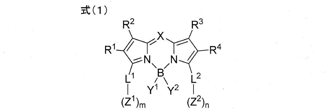
式中、XはCR5又はNを示す。R5はアルキル基、アルケニル基、アルキニル基、アリール基又はヘテロアリール基を示す。
R1~R4は、それぞれ独立に、アルキル基、アルケニル基、アルキニル基、アリール基、アルコキシ基、アルキルチオ基、ヘテロアリール基、アミノ基又はハロゲン原子を示す。
L1及びL2は、それぞれ独立に、単結合又は連結基を示す。
Z1及びZ2は、それぞれ独立に、酸性基又はその塩を示し、m及びnは、それぞれ独立に、1以上の整数を示す。
Y1及びY2は、それぞれ独立に、ハロゲン原子、アルキニル基、アリール基、ヘテロアリール基、アルコキシ基、アリールオキシ基、ヘテロアリールオキシ基、アルキルチオ基、アリールチオ基又はヘテロアリールチオ基を示す。
In the formula, X represents CR 5 or N. R 5 represents an alkyl group, an alkenyl group, an alkynyl group, an aryl group or a heteroaryl group.
R 1 to R 4 each independently represents an alkyl group, an alkenyl group, an alkynyl group, an aryl group, an alkoxy group, an alkylthio group, a heteroaryl group, an amino group, or a halogen atom.
L 1 and L 2 each independently represent a single bond or a linking group.
Z 1 and Z 2 each independently represent an acidic group or a salt thereof, and m and n each independently represents an integer of 1 or more.
Y 1 and Y 2 each independently represent a halogen atom, an alkynyl group, an aryl group, a heteroaryl group, an alkoxy group, an aryloxy group, a heteroaryloxy group, an alkylthio group, an arylthio group or a heteroarylthio group.
<2>L1及びL2が、いずれも、脂肪族不飽和炭化水素基、芳香族炭化水素環基若しくは芳香族ヘテロ環基、又は、脂肪族不飽和炭化水素基、芳香族炭化水素環基及び芳香族ヘテロ環基からなる群より選択される2個以上の基を組み合わせてなる連結基を示す<1>に記載の光電変換素子。
<3>L1及びL2が、いずれも、共役連結基である<1>又は<2>に記載の光電変換素子。
<4>L1及びL2が、いずれも、脂肪族不飽和炭化水素基、芳香族炭化水素環基及び芳香族ヘテロ環基からなる群より選択される2個以上の基を組み合わせてなる連結基である<1>~<3>のいずれか1つに記載の光電変換素子。
<5>L1及びL2が、いずれも、アルケニレン基、アルキニレン基、芳香族炭化水素環基及び芳香族ヘテロ環基からなる群より選択される2個以上の基を組み合わせてなる連結基である<1>~<4>のいずれか1つに記載の光電変換素子。 <2> Each of L 1 and L 2 is an aliphatic unsaturated hydrocarbon group, an aromatic hydrocarbon ring group or an aromatic heterocyclic group, or an aliphatic unsaturated hydrocarbon group, an aromatic hydrocarbon ring group And the photoelectric conversion element according to <1>, which represents a linking group formed by combining two or more groups selected from the group consisting of an aromatic heterocyclic group.
<3> The photoelectric conversion element according to <1> or <2>, in which L 1 and L 2 are both conjugated linking groups.
<4> Linkage in which L 1 and L 2 are each a combination of two or more groups selected from the group consisting of an aliphatic unsaturated hydrocarbon group, an aromatic hydrocarbon ring group, and an aromatic heterocyclic group The photoelectric conversion element according to any one of <1> to <3>, which is a group.
<5> L 1 and L 2 are both a linking group formed by combining two or more groups selected from the group consisting of an alkenylene group, an alkynylene group, an aromatic hydrocarbon ring group, and an aromatic heterocyclic group. The photoelectric conversion element according to any one of <1> to <4>.
<6>L1及びL2が、いずれも、下記式(L)で表される基である<1>~<5>のいずれか1つに記載の光電変換素子。
式(L) *-LL1-ArL-***
式中、LL1は下記式(L-1)~(L-4)のいずれかで表される基を示す。ArLは芳香族炭化水素環基又は芳香族ヘテロ環基を示す。*は式(1)中のピロール環との結合部を示し、***は式(1)中のZ1又はZ2との結合部を示す。

式中、R21~R28は、それぞれ独立に、水素原子又は置換基を示し、Aは酸素原子又は硫黄原子を示す。*は式(1)中のピロール環との結合部を示し、**はArLとの結合部を示す。 <6> The photoelectric conversion element according to any one of <1> to <5>, wherein L 1 and L 2 are both groups represented by the following formula (L).
Formula (L) * -L L1 -Ar L -***
In the formula, L L1 represents a group represented by any of the following formulas (L-1) to (L-4). Ar L represents an aromatic hydrocarbon ring group or an aromatic heterocyclic group. * Represents a bond to the pyrrole ring in formula (1), and *** represents a bond to Z 1 or Z 2 in formula (1).
In the formula, R 21 to R 28 each independently represent a hydrogen atom or a substituent, and A represents an oxygen atom or a sulfur atom. * Represents a bond to the pyrrole ring in formula (1), and ** represents a bond to Ar L.
式(L) *-LL1-ArL-***
式中、LL1は下記式(L-1)~(L-4)のいずれかで表される基を示す。ArLは芳香族炭化水素環基又は芳香族ヘテロ環基を示す。*は式(1)中のピロール環との結合部を示し、***は式(1)中のZ1又はZ2との結合部を示す。
式中、R21~R28は、それぞれ独立に、水素原子又は置換基を示し、Aは酸素原子又は硫黄原子を示す。*は式(1)中のピロール環との結合部を示し、**はArLとの結合部を示す。 <6> The photoelectric conversion element according to any one of <1> to <5>, wherein L 1 and L 2 are both groups represented by the following formula (L).
Formula (L) * -L L1 -Ar L -***
In the formula, L L1 represents a group represented by any of the following formulas (L-1) to (L-4). Ar L represents an aromatic hydrocarbon ring group or an aromatic heterocyclic group. * Represents a bond to the pyrrole ring in formula (1), and *** represents a bond to Z 1 or Z 2 in formula (1).
In the formula, R 21 to R 28 each independently represent a hydrogen atom or a substituent, and A represents an oxygen atom or a sulfur atom. * Represents a bond to the pyrrole ring in formula (1), and ** represents a bond to Ar L.
<7>L1及びL2が、いずれも、スチリル基である<1>~<6>のいずれか1つに記載の光電変換素子。
<8>m及びnが、いずれも、1である<1>~<7>のいずれか1つに記載の光電変換素子。
<9>Z1及びZ2が、いずれも、-COOH、-SO3H、-PO(OH)2、-OH及び-SHから選ばれる酸性基又はその塩である<1>~<8>のいずれか1つに記載の光電変換素子
<10>上記<1>~<9>のいずれか1つに記載の光電変換素子を備えた色素増感太陽電池。 <7> The photoelectric conversion element according to any one of <1> to <6>, wherein L 1 and L 2 are both styryl groups.
<8> The photoelectric conversion element according to any one of <1> to <7>, wherein m and n are all 1.
<9> Each of Z 1 and Z 2 is an acidic group selected from —COOH, —SO 3 H, —PO (OH) 2 , —OH and —SH or a salt thereof <1> to <8><10> A dye-sensitized solar cell comprising the photoelectric conversion element according to any one of <1> to <9> above.
<11>下記式(1)で表されるジピロメテン錯体化合物。

式中、XはCR5又はNを示す。R5はアルキル基、アルケニル基、アルキニル基、アリール基又はヘテロアリール基を示す。
R1~R4は、それぞれ独立に、アルキル基、アルケニル基、アルキニル基、アリール基、アルコキシ基、アルキルチオ基、ヘテロアリール基、アミノ基又はハロゲン原子を示す。
L1及びL2は、それぞれ独立に、単結合又は連結基を示す。
Z1及びZ2は、それぞれ独立に、酸性基又はその塩を示し、m及びnは、それぞれ独立に、1以上の整数を示す。
Y1及びY2は、それぞれ独立に、ハロゲン原子、アルキニル基、アリール基、ヘテロアリール基、アルコキシ基、アリールオキシ基、ヘテロアリールオキシ基、アルキルチオ基、アリールチオ基又はヘテロアリールチオ基を示す。 <11> A dipyrromethene complex compound represented by the following formula (1).
In the formula, X represents CR 5 or N. R 5 represents an alkyl group, an alkenyl group, an alkynyl group, an aryl group or a heteroaryl group.
R 1 to R 4 each independently represents an alkyl group, an alkenyl group, an alkynyl group, an aryl group, an alkoxy group, an alkylthio group, a heteroaryl group, an amino group, or a halogen atom.
L 1 and L 2 each independently represent a single bond or a linking group.
Z 1 and Z 2 each independently represent an acidic group or a salt thereof, and m and n each independently represents an integer of 1 or more.
Y 1 and Y 2 each independently represent a halogen atom, an alkynyl group, an aryl group, a heteroaryl group, an alkoxy group, an aryloxy group, a heteroaryloxy group, an alkylthio group, an arylthio group or a heteroarylthio group.
本明細書において、特段の断りがない限り、二重結合については、分子内にE型及びZ型が存在する場合、そのいずれであっても、またこれらの混合物であってもよい。
特定の符号又は式で表示された置換基、連結基若しくは配位子等(以下、置換基等という)が複数あるとき、又は、複数の置換基等を同時に規定するときには、特段の断りがない限り、それぞれの置換基等は互いに同一でも異なっていてもよい。このことは、置換基等の数の規定についても同様である。また、複数の置換基等が近接するとき(特に、隣接するとき)には、特段の断りがない限り、それらが互いに連結して環を形成していてもよい。また、特段の断りがない限り、環、例えば脂環、芳香族環、ヘテロ環は、更に縮環して縮合環を形成していてもよい。 In the present specification, unless otherwise specified, the double bond may be either E-type or Z-type in the molecule, or a mixture thereof.
When there are a plurality of substituents, linking groups, ligands, etc. (hereinafter referred to as substituents, etc.) indicated by a specific symbol or formula, or when a plurality of substituents etc. are specified simultaneously, there is no special notice. As long as each substituent is the same, it may be the same or different. The same applies to the definition of the number of substituents and the like. Further, when a plurality of substituents and the like are adjacent (particularly adjacent), they may be connected to each other to form a ring unless otherwise specified. In addition, unless otherwise specified, a ring such as an alicyclic ring, an aromatic ring, or a heterocyclic ring may be further condensed to form a condensed ring.
本明細書において、化合物(錯体及び色素を含む)の表示については、化合物そのもののほか、その塩、そのイオンを含む意味に用いる。また、本発明の効果を損なわない範囲で、構造の一部を変化させたものを含む意味である。更に、置換又は無置換を明記していない化合物については、本発明の効果を損なわない範囲で、任意の置換基を有していてもよい意味である。このことは、置換基、連結基及び配位子についても同様である。
In the present specification, the display of a compound (including a complex and a dye) is used to mean not only the compound itself but also its salt and its ion. Moreover, it is the meaning including what changed a part of structure in the range which does not impair the effect of this invention. Furthermore, it is the meaning which may have arbitrary substituents in the range which does not impair the effect of this invention about the compound which does not specify substitution or unsubstituted. The same applies to substituents, linking groups and ligands.
また、本明細書において「~」を用いて表される数値範囲は、「~」前後に記載される数値を下限値及び上限値として含む範囲を意味する。
In addition, in the present specification, a numerical range represented by using “to” means a range including numerical values described before and after “to” as a lower limit value and an upper limit value.
本発明の光電変換素子及び色素増感太陽電池は、式(1)で表されるジピロメテン錯体化合物を担持することにより、優れた光電変換効率を示す。また、本発明のジピロメテン錯体化合物は、増感色素として用いることにより、光電変換素子及び色素増感太陽電池の光電変換効率を高めることができる。
The photoelectric conversion element and the dye-sensitized solar cell of the present invention show excellent photoelectric conversion efficiency by supporting the dipyrromethene complex compound represented by the formula (1). Moreover, the dipyrromethene complex compound of this invention can raise the photoelectric conversion efficiency of a photoelectric conversion element and a dye-sensitized solar cell by using as a sensitizing dye.
[光電変換素子及び色素増感太陽電池]
本発明の光電変換素子は、導電性支持体と、電解質を含む感光体層と、電解質を含む電荷移動体層と、対極(対向電極)とを有する。感光体層と電荷移動体層と対極とがこの順で導電性支持体上に設けられている。 [Photoelectric conversion element and dye-sensitized solar cell]
The photoelectric conversion element of the present invention has a conductive support, a photoreceptor layer containing an electrolyte, a charge transfer body layer containing an electrolyte, and a counter electrode (counter electrode). The photosensitive layer, the charge transfer layer, and the counter electrode are provided on the conductive support in this order.
本発明の光電変換素子において、その感光体層を形成する半導体微粒子は、増感色素として後述する式(1)で表されるジピロメテン錯体化合物(増感色素として用いる場合、ジピロメテン錯体色素ともいう。)を担持している。ここで、ジピロメテン錯体色素が半導体微粒子の表面に担持される態様は、半導体微粒子の表面に吸着している態様、半導体微粒子の表面に堆積している態様、及び、これらが混在した態様等を包含する。吸着は、化学吸着と物理吸着とを含み、化学吸着が好ましい。
ジピロメテン錯体化合物は、後述する酸性基(吸着基ともいう。)を介して半導体微粒子に吸着されていることが好ましく、このとき、酸性基は、プロトンを放出して解離したアニオン若しくはその塩となっていてもよい。酸性基が塩となるときの対イオンについては後述するものと同義である。
ジピロメテン錯体化合物が酸性基を介して半導体微粒子に吸着している場合、この酸性基は1個でも2個以上でもよい。 In the photoelectric conversion element of the present invention, the semiconductor fine particles forming the photoreceptor layer are also referred to as a dipyrromethene complex compound represented by the following formula (1) as a sensitizing dye (also referred to as a dipyrromethene complex dye when used as a sensitizing dye). ). Here, the aspect in which the dipyrromethene complex dye is supported on the surface of the semiconductor fine particle includes an aspect in which the dipyrromethene complex dye is adsorbed on the surface of the semiconductor fine particle, an aspect in which the dipyrromethene complex dye is deposited on the surface of the semiconductor fine particle To do. The adsorption includes chemical adsorption and physical adsorption, and chemical adsorption is preferable.
The dipyrromethene complex compound is preferably adsorbed on the semiconductor fine particles via an acidic group (also referred to as an adsorbing group) described later. At this time, the acidic group becomes an anion or a salt thereof dissociated by releasing a proton. It may be. The counter ion when the acidic group becomes a salt has the same meaning as described later.
When the dipyrromethene complex compound is adsorbed on the semiconductor fine particles via an acidic group, the acidic group may be one or two or more.
本発明の光電変換素子は、本発明で規定する構成以外の構成は特に限定されず、光電変換素子に関する公知の構成を採用できる。本発明の光電変換素子を構成する上記各層は、目的に応じて設計され、例えば、単層に形成されても、複層に形成されてもよい。また、必要により上記各層以外の層を有してもよい。
The photoelectric conversion element of the present invention is not particularly limited in structure other than the structure defined in the present invention, and a known structure relating to the photoelectric conversion element can be adopted. Each of the layers constituting the photoelectric conversion element of the present invention is designed according to the purpose, and may be formed in a single layer or multiple layers, for example. Moreover, you may have layers other than said each layer if needed.
本発明の色素増感太陽電池は、本発明の光電変換素子を用いてなる。
以下、本発明の光電変換素子及び色素増感太陽電池の好ましい実施形態について説明する。 The dye-sensitized solar cell of the present invention uses the photoelectric conversion element of the present invention.
Hereinafter, preferred embodiments of the photoelectric conversion element and the dye-sensitized solar cell of the present invention will be described.
図1に示されるシステム100は、本発明の第1態様の光電変換素子10を、外部回路6で動作手段M(例えば電動モーター)に仕事をさせる電池用途に応用したものである。
光電変換素子10は、導電性支持体1と、色素(ジピロメテン錯体色素)21を担持することにより増感された半導体微粒子22、及び、半導体微粒子22間に電解質を含む感光体層2と、正孔輸送層である電荷移動体層3と、対極4とからなる。
光電変換素子10において、感光体層2は、半導体微粒子22に式(1)で表されるジピロメテン錯体色素が吸着されており、酸化物半導体電極ともいう。また、受光電極5は、導電性支持体1及び感光体層2を有し、作用電極として機能する。 Asystem 100 shown in FIG. 1 is an application of the photoelectric conversion element 10 according to the first aspect of the present invention to a battery application in which an operation means M (for example, an electric motor) is caused to work by an external circuit 6.
Thephotoelectric conversion element 10 includes a conductive support 1, semiconductor fine particles 22 sensitized by carrying a dye (dipyrromethene complex dye) 21, a photoreceptor layer 2 containing an electrolyte between the semiconductor fine particles 22, It consists of a charge transfer layer 3 as a hole transport layer and a counter electrode 4.
In thephotoelectric conversion element 10, the dipyrromethene complex dye represented by the formula (1) is adsorbed to the semiconductor fine particles 22 in the photoreceptor layer 2, which is also referred to as an oxide semiconductor electrode. The light receiving electrode 5 has a conductive support 1 and a photoreceptor layer 2 and functions as a working electrode.
光電変換素子10は、導電性支持体1と、色素(ジピロメテン錯体色素)21を担持することにより増感された半導体微粒子22、及び、半導体微粒子22間に電解質を含む感光体層2と、正孔輸送層である電荷移動体層3と、対極4とからなる。
光電変換素子10において、感光体層2は、半導体微粒子22に式(1)で表されるジピロメテン錯体色素が吸着されており、酸化物半導体電極ともいう。また、受光電極5は、導電性支持体1及び感光体層2を有し、作用電極として機能する。 A
The
In the
光電変換素子10を応用したシステム100において、感光体層2に入射した光は、ジピロメテン錯体色素21を励起する。励起されたジピロメテン錯体色素21はエネルギーの高い電子を有しており、この電子がジピロメテン錯体色素21から半導体微粒子22の伝導帯に渡され、更に拡散によって導電性支持体1に到達する。このときジピロメテン錯体色素21は酸化体(カチオン)となっている。導電性支持体1に到達した電子が外部回路6で仕事をしながら、対極4、電荷移動体層3を経由してジピロメテン錯体色素21の酸化体に到達し、この酸化体が還元される。このような、上記ジピロメテン錯体色素の励起及び電子移動のサイクルを繰り返すことにより、システム100が太陽電池として機能する。
In the system 100 to which the photoelectric conversion element 10 is applied, the light incident on the photoreceptor layer 2 excites the dipyrromethene complex dye 21. The excited dipyrromethene complex dye 21 has electrons with high energy, and these electrons are transferred from the dipyrromethene complex dye 21 to the conduction band of the semiconductor fine particles 22 and further reach the conductive support 1 by diffusion. At this time, the dipyrromethene complex dye 21 is an oxidant (cation). Electrons that reach the conductive support 1 reach the oxidized form of the dipyrromethene complex dye 21 via the counter electrode 4 and the charge transfer layer 3 while working in the external circuit 6, and the oxidized form is reduced. By repeating the cycle of excitation and electron transfer of the dipyrromethene complex dye, the system 100 functions as a solar cell.
図2に示される色素増感太陽電池20は、本発明の第2態様の光電変換素子により構成されている。
色素増感太陽電池20となる光電変換素子は、図1に示す光電変換素子に対して、導電性支持体41及び感光体層42の構成、及び、スペーサーSを有する点で異なるが、それらの点以外は図1に示す光電変換素子10と同様に構成されている。すなわち、導電性支持体41は、基板44と、基板44の表面に成膜された透明導電膜43とからなる2層構造を有している。また、感光体層42は、半導体層45と、半導体層45に隣接して成膜された光散乱層46とからなる2層構造を有している。この感光体層42は、少なくとも、感光体層42を形成する半導体微粒子に式(1)で表されるジピロメテン錯体色素が吸着されており、酸化物半導体電極ともいう。導電性支持体41と対極48との間にはスペーサーSが設けられている。色素増感太陽電池20において、40は受光電極であり、47は電荷移動体層である。 The dye-sensitizedsolar cell 20 shown in FIG. 2 is configured by the photoelectric conversion element of the second aspect of the present invention.
Although the photoelectric conversion element used as the dye-sensitizedsolar cell 20 differs with respect to the photoelectric conversion element shown in FIG. Except for this point, the photoelectric conversion element 10 is configured in the same manner as the photoelectric conversion element 10 shown in FIG. That is, the conductive support 41 has a two-layer structure including a substrate 44 and a transparent conductive film 43 formed on the surface of the substrate 44. The photoreceptor layer 42 has a two-layer structure including a semiconductor layer 45 and a light scattering layer 46 formed adjacent to the semiconductor layer 45. In this photoreceptor layer 42, at least the dipyrromethene complex dye represented by the formula (1) is adsorbed on the semiconductor fine particles forming the photoreceptor layer 42, and is also referred to as an oxide semiconductor electrode. A spacer S is provided between the conductive support 41 and the counter electrode 48. In the dye-sensitized solar cell 20, reference numeral 40 denotes a light receiving electrode, and 47 denotes a charge transfer body layer.
色素増感太陽電池20となる光電変換素子は、図1に示す光電変換素子に対して、導電性支持体41及び感光体層42の構成、及び、スペーサーSを有する点で異なるが、それらの点以外は図1に示す光電変換素子10と同様に構成されている。すなわち、導電性支持体41は、基板44と、基板44の表面に成膜された透明導電膜43とからなる2層構造を有している。また、感光体層42は、半導体層45と、半導体層45に隣接して成膜された光散乱層46とからなる2層構造を有している。この感光体層42は、少なくとも、感光体層42を形成する半導体微粒子に式(1)で表されるジピロメテン錯体色素が吸着されており、酸化物半導体電極ともいう。導電性支持体41と対極48との間にはスペーサーSが設けられている。色素増感太陽電池20において、40は受光電極であり、47は電荷移動体層である。 The dye-sensitized
Although the photoelectric conversion element used as the dye-sensitized
色素増感太陽電池20は、光電変換素子10を応用したシステム100と同様に、感光体層42に光が入射することにより、太陽電池として機能する。
The dye-sensitized solar cell 20 functions as a solar cell when light enters the photoreceptor layer 42 as in the system 100 to which the photoelectric conversion element 10 is applied.
本発明の光電変換素子及び色素増感太陽電池は、後述するように、800nm以上の長波長領域においても外部量子収率が高く、優れた光電変換効率を示す。この優れた光電変換効率は、晴天時の太陽光照射下(高照度環境下ともいう)においても、また、晴天時の太陽光に比べて照度が低い低照度環境下においても、示される。
低照度環境とは、特に限定されず、例えば照度が1万ルクス以下の環境をいう。このような低照度環境としては、例えば、曇天若しくは雨天時等の低照度太陽光環境、又は、屋内環境若しくは蛍光灯等の照明下による低照度環境が挙げられる。 As will be described later, the photoelectric conversion element and the dye-sensitized solar cell of the present invention have a high external quantum yield even in a long wavelength region of 800 nm or more, and exhibit excellent photoelectric conversion efficiency. This excellent photoelectric conversion efficiency is exhibited even under sunlight irradiation (also referred to as a high illuminance environment) in fine weather, and also in a low illuminance environment in which the illuminance is low compared to sunlight in fine weather.
The low illuminance environment is not particularly limited, and refers to an environment having an illuminance of 10,000 lux or less, for example. Examples of such a low illuminance environment include a low illuminance sunlight environment such as in cloudy weather or rainy weather, or a low illuminance environment under illumination such as an indoor environment or a fluorescent lamp.
本発明の光電変換素子及び色素増感太陽電池は、上記の好ましい態様に限定されず、各態様の構成等は、本発明の趣旨を逸脱しない範囲で、各態様間で適宜組み合わせることができる。
The photoelectric conversion element and the dye-sensitized solar cell of the present invention are not limited to the above-described preferred embodiments, and the configuration of each embodiment can be appropriately combined between the embodiments without departing from the gist of the present invention.
本発明において、光電変換素子又は色素増感太陽電池に用いられる材料及び各部材は通常の方法により調製することができる。例えば、米国特許第4,927,721号明細書、米国特許第4,684,537号明細書、米国特許第5,084,365号明細書、米国特許第5,350,644号明細書、米国特許第5,463,057号明細書、米国特許第5,525,440号明細書、特開平7-249790号公報、特開2001-185244号公報、特開2001-210390号公報、特開2003-217688号公報、特開2004-220974号公報、特開2008-135197号公報を参照することができる。
In the present invention, materials and members used for the photoelectric conversion element or the dye-sensitized solar cell can be prepared by a usual method. For example, US Pat. No. 4,927,721, US Pat. No. 4,684,537, US Pat. No. 5,084,365, US Pat. No. 5,350,644, U.S. Pat. No. 5,463,057, U.S. Pat. No. 5,525,440, JP-A-7-249790, JP-A 2001-185244, JP-A 2001-210390, JP Reference can be made to JP2003-217688A, JP2004220974A, and JP2008-135197A.
<式(1)で表されるジピロメテン錯体化合物>
次に、本発明に用いるジピロメテン錯体化合物について、説明する。
ジピロメテン錯体化合物は下記式(1)で表される。このような構造を有するジピロメテン錯体化合物は、光電変換素子及び色素増感太陽電池に高い光電変換効率を付与する。 <Dipyrromethene Complex Compound Represented by Formula (1)>
Next, the dipyrromethene complex compound used in the present invention will be described.
The dipyrromethene complex compound is represented by the following formula (1). The dipyrromethene complex compound having such a structure imparts high photoelectric conversion efficiency to the photoelectric conversion element and the dye-sensitized solar cell.
式(1)で表されるジピロメテン錯体化合物が光電変換素子及び色素増感太陽電池に上記優れた性能を付与できる理由の詳細についてはまだ定かではないが次のように考えられる。
式(1)で表されるジピロメテン錯体化合物は、ジピロメテン骨格の3位及び5位に酸性基(式(1)におけるZ1及びZ2)を有しており、更に好ましくは2位及び6位に置換基(式(1)におけるR1及びR4)を有している。これにより、半導体微粒子に強固に吸着して半導体微粒子から脱着しにくいため、吸着安定性が向上する。その結果、800nm以上の長波長領域の光の吸収能が高くなる。更には、2位及び6位に置換基を有しており、これに加えて酸性基が連結基を介してジピロメテン骨格に導入されていると、長波長領域の光をより効果的に吸収できる。そのため、短波長から長波長までの広い波長領域の光によりジピロメテン錯体化合物が励起され、生じた電子が半導体微粒子に注入される。その結果、光電変換効率が向上すると考えられる。 Although the details of the reason why the dipyrromethene complex compound represented by the formula (1) can impart the above-described excellent performance to the photoelectric conversion element and the dye-sensitized solar cell are not clear yet, it is considered as follows.
The dipyrromethene complex compound represented by the formula (1) has acidic groups (Z 1 and Z 2 in the formula (1)) at the 3rd and 5th positions of the dipyrromethene skeleton, and more preferably the 2nd and 6th positions. Have substituents (R 1 and R 4 in formula (1)). Accordingly, the adsorption stability is improved because the semiconductor fine particles are strongly adsorbed and are not easily desorbed from the semiconductor fine particles. As a result, the ability to absorb light in a long wavelength region of 800 nm or more is increased. Furthermore, it has substituents at the 2-position and the 6-position, and in addition to this, when an acidic group is introduced into the dipyrromethene skeleton via a linking group, light in the long wavelength region can be absorbed more effectively. . Therefore, the dipyrromethene complex compound is excited by light in a wide wavelength region from a short wavelength to a long wavelength, and the generated electrons are injected into the semiconductor fine particles. As a result, it is considered that the photoelectric conversion efficiency is improved.
本発明において、式(1)で表されるジピロメテン錯体色素は、光学異性体、幾何異性体、結合異性体、イオン化異性体等の異性体が存在する場合、これらの異性体のいずれであってもよく、またこれらの異性体の混合物であってもよい。
In the present invention, the dipyrromethene complex dye represented by the formula (1) is an isomer such as an optical isomer, a geometric isomer, a bond isomer, an ionized isomer, and any of these isomers. It may also be a mixture of these isomers.
式(1)で表される化合物は、光電変換素子中に組み込まれた状態において、周囲の材料との酸化還元反応により酸化された状態に変化することがある。
The compound represented by the formula (1) may change to an oxidized state by an oxidation-reduction reaction with a surrounding material in a state where the compound is incorporated in the photoelectric conversion element.

式(1)において、XはCR5又はNを示し、CR5が好ましい。
R5としては、アルキル基、アルケニル基、アルキニル基、アリール基又はヘテロアリール基を示す。R5として採りうるこれらの基は、それぞれ、後述する置換基群Tの対応する基における好ましい範囲等が適用される。ただし、後述するように、R5として採りうるアルキル基及びアルケニル基には、それぞれ、シクロアルキル基及びシクロアルケニル基が包含される。
R5として採りうるアリール基としては、例えば、フェニル又はナフチル等が挙げられ、フェニルが好ましい。
R5として採りうるヘテロアリール基としては、例えば、チオフェン環、フラン環、チアゾール環、ピロール環、オキサゾール環、イミダゾール環、ピラゾール環又はトリアゾール環等の5員環の各基、ピリジン環、ピラジン環、ピリミジン環、ピリダジン環、トリアジン環又はテトラジン環の6員環の各基が挙げられる。
R5は、アリール基又はヘテロアリール基が好ましく、アリール基がより好ましく、フェニルが更に好ましい。 In the formula (1), X represents CR 5 or N, and CR 5 is preferable.
R 5 represents an alkyl group, an alkenyl group, an alkynyl group, an aryl group or a heteroaryl group. For these groups that can be adopted as R 5 , preferred ranges and the like in the corresponding groups of the substituent group T described later are applied. However, as described later, the alkyl group and alkenyl group which can be adopted as R 5 include a cycloalkyl group and a cycloalkenyl group, respectively.
Examples of the aryl group that can be adopted as R 5 include phenyl and naphthyl, and phenyl is preferable.
Examples of the heteroaryl group that can be adopted as R 5 include a thiophene ring, a furan ring, a thiazole ring, a pyrrole ring, an oxazole ring, an imidazole ring, a pyrazole ring, and a 5-membered ring group such as a triazole ring, a pyridine ring, and a pyrazine ring. , Pyrimidine ring, pyridazine ring, triazine ring or tetrazine ring 6-membered ring.
R 5 is preferably an aryl group or a heteroaryl group, more preferably an aryl group, and still more preferably phenyl.
R5として採りうる上記各基は、更に置換基を有していてもよい。更に有していてもよい置換基としては、特に限定されず、後述する置換基群Tから選ばれる置換基が好ましい。より好ましくは、アルキル基、アルコキシ基、アリール基、アミノ基、ハロゲン原子が挙げられ、アルキル基又はハロゲン原子がさらに好ましく、含フッ素アルキル基(フッ化アルキル基)又はフッ素原子が特に好ましい。R5が更に置換基を有する場合、更に有する置換基の数は、1個以上であれば特に限定されず、例えば、1~16個が好ましく、1~12個がより好ましく、2~8個が更に好ましい。
更に置換基を有する基として、例えば、(テトラ若しくはペンタ)フルオロフェニル、(モノ-、ジ-若しくはトリ-)(トリフルオロメチル)フェニル、アミノ若しくはアルコキシフェニル、(モノ-、ジ-若しくはトリ-)アルキルフェニル、(アルキル)フェニルエテニル、又は、フェニルエチニル等が挙げられる。
R5として採りうる上記各基は、後述する酸性基を有していないことが好ましい。 Each of the above groups that can be adopted as R 5 may further have a substituent. Further, the substituent that may be included is not particularly limited, and a substituent selected from the substituent group T described later is preferable. More preferably, an alkyl group, an alkoxy group, an aryl group, an amino group, and a halogen atom are mentioned, an alkyl group or a halogen atom is more preferable, and a fluorine-containing alkyl group (fluorinated alkyl group) or a fluorine atom is particularly preferable. When R 5 further has a substituent, the number of further substituents is not particularly limited as long as it is 1 or more. For example, 1 to 16 is preferable, 1 to 12 is more preferable, and 2 to 8 is preferable. Is more preferable.
Further, as a group having a substituent, for example, (tetra or penta) fluorophenyl, (mono-, di- or tri-) (trifluoromethyl) phenyl, amino or alkoxyphenyl, (mono-, di- or tri-) Examples thereof include alkylphenyl, (alkyl) phenylethenyl, phenylethynyl and the like.
Each of the above groups that can be employed as R 5 preferably does not have an acidic group described later.
式(1)において、R1~R4は、それぞれ、アルキル基、アルケニル基、アルキニル基、アリール基、アルコキシ基、アルキルチオ基、ヘテロアリール基、アミノ基又はハロゲン原子を示す。
R1~R4として採りうる上記各基又はハロゲン原子は、それぞれ、後述する置換基群Tの対応する基又はハロゲン原子における好ましい範囲等が適用される。ただし、後述するように、R1~R4として採りうる、アルキル基、アルケニル基、アルコキシ基及びアルキルチオ基は、それぞれ、置換基群Tにおける、シクロアルキル基、シクロアルケニル基、シクロアルキルオキシ基及びシクロアルキルチオ基が包含される。
R1及びR4は、それぞれ、アルキル基、アルケニル基、アルキニル基、アリール基、ヘテロアリール基が好ましく、アルキル基、アルキニル基、アリール基又はヘテロアリール基がより好ましい。
R2及びR3は、それぞれ、アルキル基、アルケニル基、アルキニル基、アリール基、ヘテロアリール基が好ましく、アルキル基、アルキニル基、アリール基又はヘテロアリール基がより好ましく、アルキル基が更に好ましい。
R1~R4において、R1及びR4が同一であり、R2及びR3が同一であることが好ましい。このとき、R1及びR2とR3及びR4とは異なっていてもよい。 In the formula (1), R 1 to R 4 each represents an alkyl group, an alkenyl group, an alkynyl group, an aryl group, an alkoxy group, an alkylthio group, a heteroaryl group, an amino group, or a halogen atom.
For each of the above groups or halogen atoms that can be adopted as R 1 to R 4 , preferred ranges of the corresponding groups or halogen atoms in the substituent group T described later are applied. However, as described later, an alkyl group, an alkenyl group, an alkoxy group, and an alkylthio group that can be adopted as R 1 to R 4 are, respectively, a cycloalkyl group, a cycloalkenyl group, a cycloalkyloxy group in the substituent group T, and A cycloalkylthio group is included.
R 1 and R 4 are each preferably an alkyl group, an alkenyl group, an alkynyl group, an aryl group, or a heteroaryl group, and more preferably an alkyl group, an alkynyl group, an aryl group, or a heteroaryl group.
R 2 and R 3 are each preferably an alkyl group, an alkenyl group, an alkynyl group, an aryl group or a heteroaryl group, more preferably an alkyl group, an alkynyl group, an aryl group or a heteroaryl group, and even more preferably an alkyl group.
In R 1 to R 4 , R 1 and R 4 are preferably the same, and R 2 and R 3 are preferably the same. At this time, R 1 and R 2 may be different from R 3 and R 4 .
R1~R4として採りうる上記各基は、更に置換基を有していてもよい。更に有していてもよい置換基としては、特に限定されず、後述する置換基群Tから選ばれる置換基が好ましい。より好ましくは、アルキル基、アルケニル基、アルキニル基、アリール基、ハロゲン原子、アルコキシ基又はアミノ基であり、更に好ましくは、アルキル基、アリール基、アルコキシ基又はハロゲン原子である。R1~R4が更に置換基を有する場合、更に有する置換基の数は、1個以上であれば特に限定されず、例えば、1~16個が好ましく、2~12個が更に好ましい。
更に置換基を有する基として、例えば、(テトラ若しくはペンタ)フルオロフェニル、(モノ-、ジ-若しくはトリ-)(トリフルオロメチル)フェニル、(モノ-、ジ-若しくはトリ-)アルキルフェニル、(モノ-、ジ-若しくはトリ-)アルキルフェニルエテニル、(モノ-、ジ-若しくはトリ-)アルキルフェニルエチニル、又は、アルキルチエニル等が挙げられる。 Each of the above groups that can be adopted as R 1 to R 4 may further have a substituent. Further, the substituent that may be included is not particularly limited, and a substituent selected from the substituent group T described later is preferable. An alkyl group, an alkenyl group, an alkynyl group, an aryl group, a halogen atom, an alkoxy group or an amino group is more preferable, and an alkyl group, an aryl group, an alkoxy group or a halogen atom is still more preferable. When R 1 to R 4 further have a substituent, the number of further substituents is not particularly limited as long as it is 1 or more. For example, 1 to 16 is preferable, and 2 to 12 is more preferable.
Further, as a group having a substituent, for example, (tetra or penta) fluorophenyl, (mono-, di- or tri-) (trifluoromethyl) phenyl, (mono-, di- or tri-) alkylphenyl, (mono -, Di- or tri-) alkylphenylethenyl, (mono-, di- or tri-) alkylphenylethynyl, or alkylthienyl.
R1~R4として採りうる上記各基は、後述する酸性基を有していないことが好ましい。
Each of the above groups that can be taken as R 1 to R 4 preferably does not have an acidic group described later.
式(1)において、L1及びL2は、それぞれ、単結合又は連結基を示し、連結基が好ましい。
L1及びL2として採りうる連結基は、IPCE及び光電変換効率の点で、式(1)中のジピロメテン骨格(ピロール環)と共役する連結基(共役連結基)であることが好ましい。L1及びL2として採りうる連結基としては、脂肪族不飽和炭化水素基、芳香族炭化水素環基若しくは芳香族ヘテロ環基、又は、脂肪族不飽和炭化水素基、芳香族炭化水素環基及び芳香族ヘテロ環基からなる群より選択される2個以上の基を組み合わせてなる連結基が好ましく、上記2個以上の基を組み合わせてなる連結基がより好ましい。 In Formula (1), L 1 and L 2 each represent a single bond or a linking group, and a linking group is preferred.
The linking group that can be taken as L 1 and L 2 is preferably a linking group (conjugated linking group) conjugated with the dipyrromethene skeleton (pyrrole ring) in the formula (1) in terms of IPCE and photoelectric conversion efficiency. Examples of the linking group that can be adopted as L 1 and L 2 include an aliphatic unsaturated hydrocarbon group, an aromatic hydrocarbon ring group, an aromatic heterocyclic group, an aliphatic unsaturated hydrocarbon group, and an aromatic hydrocarbon ring group. And a linking group formed by combining two or more groups selected from the group consisting of aromatic heterocyclic groups, and a linking group formed by combining the two or more groups is more preferable.
脂肪族不飽和炭化水素基としては、内部又は末端に炭素-炭素不飽和結合を少なくとも1個有する基が挙げられ、エチレン系炭化水素基又はアセチレン系炭化水素基が好ましく挙げられる。脂肪族不飽和炭化水素基において、炭素-炭素不飽和結合は末端に有するものが好ましい。
Examples of the aliphatic unsaturated hydrocarbon group include a group having at least one carbon-carbon unsaturated bond inside or at the end, and an ethylene hydrocarbon group or an acetylene hydrocarbon group is preferable. In the aliphatic unsaturated hydrocarbon group, a carbon-carbon unsaturated bond having a terminal is preferable.
エチレン系炭化水素基としては、基内に少なくとも1個の炭素-炭素二重結合を有する炭化水素基であり、-CRL=CRL-で表される基を含む基が挙げられ、-CRL=CRL-で表される基が好ましい。エチレン系炭化水素基の炭素数は、好ましくは2~20であり、より好ましくは2~12であり、更に好ましくは2である。RLは水素原子又は置換基を表し、水素原子が好ましい。このエチレン系炭化水素基は置換基を有していてもよい。エチレン系炭化水素基が有していてもよい置換基及びRLとして採りうる置換基としては、特に限定されず、後述する置換基群Tから選ばれる置換基が挙げられる。この置換基は、更に置換基を有していてもよい。このエチレン系炭化水素基は3価以上の基である場合、基中の水素原子(水素原子を採るRLを含む。)を所定数((価数-2)個)取り除いた基となる。例えば、後述するm又はnがそれぞれ2以上の整数である場合、エチレン系炭化水素基は基中の水素原子を(m-1)個又は(n-1)個以上取り除いた基となる。
エチレン系炭化水素基は、2価(m又はnが1である場合)の基(アルケニレン基)が好ましく、-CRL=CRL-基で表される基(エテニレン基)がより好ましい。 Examples of the ethylene-based hydrocarbon group include a hydrocarbon group having at least one carbon-carbon double bond in the group, and a group containing a group represented by —CR L ═CR L —. L = CR L - group represented by are preferred. The number of carbon atoms of the ethylene-based hydrocarbon group is preferably 2 to 20, more preferably 2 to 12, and still more preferably 2. R L represents a hydrogen atom or a substituent, and is preferably a hydrogen atom. This ethylene-based hydrocarbon group may have a substituent. The substituent that the ethylene hydrocarbon group may have and the substituent that can be taken as RL are not particularly limited, and examples thereof include a substituent selected from the substituent group T described later. This substituent may further have a substituent. When this ethylene-based hydrocarbon group is a trivalent or higher group, it is a group obtained by removing a predetermined number ((valence-2)) of hydrogen atoms (including RL that takes a hydrogen atom) in the group. For example, when m or n described later is an integer of 2 or more, the ethylene-based hydrocarbon group is a group obtained by removing (m−1) or (n−1) or more hydrogen atoms in the group.
The ethylene-based hydrocarbon group is preferably a divalent group (when m or n is 1) (alkenylene group), and more preferably a group represented by -CR L = CR L -group (ethenylene group).
アセチレン系炭化水素基としては、基内に少なくとも1個の炭素-炭素三重結合を有する炭化水素基であり、-C≡C-で表される基を含む基が挙げられ、-C≡C-で表される基が好ましい。アセチレン系炭化水素基の炭素数は、好ましくは2~20であり、より好ましくは2~12であり、更に好ましくは2である。アセチレン系炭化水素基は置換基を有していてもよい。アセチレン系炭化水素基が有していてもよい置換基としては、上記エチレン系炭化水素基が有していてもよい上記置換基と同義である。アセチレン系炭化水素基は3価以上の基である場合、基中の水素原子を所定数((価数-2)個)取り除いた基となる。例えば、後述するm又はnがそれぞれ2以上の整数である場合、アセチレン系炭化水素基は基中の水素原子を(m-1)個又は(n-1)個以上取り除いた基となる。
アセチレン系炭化水素基は、2価(例えば、m又はnが1である場合)の基(アルキニレン基)が好ましく、-C≡C-で表される基(エチニレン基)という。 Examples of the acetylene hydrocarbon group include a hydrocarbon group having at least one carbon-carbon triple bond in the group, and a group containing a group represented by —C≡C—, and —C≡C— The group represented by these is preferable. The carbon number of the acetylene hydrocarbon group is preferably 2 to 20, more preferably 2 to 12, and still more preferably 2. The acetylene hydrocarbon group may have a substituent. The substituent that the acetylene hydrocarbon group may have has the same meaning as the substituent that the ethylene hydrocarbon group may have. When the acetylene hydrocarbon group is a trivalent or higher group, it is a group obtained by removing a predetermined number ((valence-2)) of hydrogen atoms in the group. For example, when m or n described later is an integer of 2 or more, the acetylene hydrocarbon group is a group obtained by removing (m−1) or (n−1) or more hydrogen atoms in the group.
The acetylene hydrocarbon group is preferably a divalent group (for example, when m or n is 1) (alkynylene group), and is referred to as a group represented by —C≡C— (ethynylene group).
芳香族炭化水素環基としては、下記置換基群Tのアリール基から水素原子を更にm個又はn個取り除いた基が挙げられる。芳香族炭化水素環基における好ましい範囲等は、下記置換基群Tのアリール基における好ましい範囲等が適用される。
また、芳香族ヘテロ環基としては、下記置換基群Tで説明されているヘテロ環基のうちの芳香族ヘテロ環基から水素原子を更にm個又はn個取り除いた基が挙げられる。芳香族ヘテロ環基における好ましい範囲等は、下記置換基群Tの芳香族ヘテロ環基における好ましい範囲等が適用される。
芳香族炭化水素環基及び芳香族ヘテロ環基は、2価の基(アリーレン基及びヘテロアリーレン基)が好ましく、例えば、上記R5として採りうるアリーレン基及びヘテロアリーレン基で挙げた基が好ましく挙げられる。 Examples of the aromatic hydrocarbon ring group include groups obtained by further removing m or n hydrogen atoms from an aryl group of the following substituent group T. As a preferable range and the like in the aromatic hydrocarbon ring group, a preferable range and the like in the aryl group of the following substituent group T is applied.
Examples of the aromatic heterocyclic group include groups obtained by further removing m or n hydrogen atoms from the aromatic heterocyclic group among the heterocyclic groups described in the substituent group T below. As the preferred range and the like for the aromatic heterocyclic group, the preferred range and the like for the aromatic heterocyclic group of the following substituent group T are applied.
The aromatic hydrocarbon ring group and the aromatic heterocyclic group are preferably divalent groups (arylene group and heteroarylene group). For example, the groups exemplified for the arylene group and heteroarylene group which can be adopted as R 5 are preferable. It is done.
脂肪族不飽和炭化水素基、芳香族炭化水素環基及び芳香族ヘテロ環基からなる群より選択される2個以上の基を組み合わせてなる連結基において、組み合わされる基は、上記群から選択される2個以上の基であれば、同一の基であってもよく、異種の基であってもよい。組み合わされる基の数は、特に限定されず、2~6個が好ましく、2~4個がより好ましく、2個又は3個が更に好ましい。
In the linking group formed by combining two or more groups selected from the group consisting of an aliphatic unsaturated hydrocarbon group, an aromatic hydrocarbon ring group and an aromatic heterocyclic group, the group to be combined is selected from the above group Two or more groups may be the same group or different groups. The number of groups to be combined is not particularly limited, preferably 2 to 6, more preferably 2 to 4, and still more preferably 2 or 3.
L1及びL2として採りうる連結基が、上述の2個以上の基を組み合わせてなる連結基である場合、アルケニレン基、アルキニレン基、芳香族炭化水素環基及び芳香族ヘテロ環基からなる群より選択される2個以上の基を組み合わせてなる連結基が好ましく、下記式(L)で表される基がより好ましい。
式(L) *-LL1-ArL-***
式(L)において、LL1は、下記式(L-1)~(L-4)のいずれかで表される基を示す。ArLは芳香族炭化水素環基又は芳香族ヘテロ環基を示し、アリーレン基又はヘテロアリーレン基が好ましい。*は上記式(1)中のピロール環との結合部を示し、***は上記式(1)中のZ1又はZ2との結合部を示す。 When the linking group that can be taken as L 1 and L 2 is a linking group formed by combining two or more groups described above, a group consisting of an alkenylene group, an alkynylene group, an aromatic hydrocarbon ring group, and an aromatic heterocyclic group A linking group formed by combining two or more selected groups is preferred, and a group represented by the following formula (L) is more preferred.
Formula (L) * -L L1 -Ar L -***
In the formula (L), L L1 represents a group represented by any of the following formulas (L-1) to (L-4). Ar L represents an aromatic hydrocarbon ring group or an aromatic heterocyclic group, preferably an arylene group or a heteroarylene group. * Represents a bond to the pyrrole ring in the above formula (1), and *** represents a bond to Z 1 or Z 2 in the above formula (1).

式(L-1)~(L-4)において、*は上記式(1)中のピロール環との結合部を示し、**はArLとの結合部を示す。
In formulas (L-1) to (L-4), * represents a bond to the pyrrole ring in formula (1), and ** represents a bond to Ar L.
R21~R28は、それぞれ独立に、水素原子又は置換基を示し、いずれも、水素原子が好ましい。
R21~R28としてとして採りうる置換基は、特に限定されず、後述する置換基群Tから選ばれる置換基が挙げられる。なかでも、アルキル基又はアルコキシ基が好ましい。この置換基は更に置換基を有していてもよい。
式(L-4)において、Aは酸素原子又は硫黄原子を示す。
LL1は、なかでも、式(L-1)、式(L-2)及び式(L-3)のいずれかで表される連結基が好ましく、式(L-1)又は式(L-2)で表される連結基がより好ましく、式(L-1)で表される連結基が更に好ましい。 R 21 to R 28 each independently represent a hydrogen atom or a substituent, and any of them is preferably a hydrogen atom.
The substituent that can be adopted as R 21 to R 28 is not particularly limited, and examples thereof include a substituent selected from the substituent group T described later. Of these, an alkyl group or an alkoxy group is preferable. This substituent may further have a substituent.
In the formula (L-4), A represents an oxygen atom or a sulfur atom.
In particular, L L1 is preferably a linking group represented by any one of formula (L-1), formula (L-2) and formula (L-3), and is represented by formula (L-1) or formula (L- The linking group represented by 2) is more preferable, and the linking group represented by formula (L-1) is more preferable.
ArLは、芳香族炭化水素環基又は芳香族ヘテロ環基であり、芳香族炭化水素環基が好ましい。
ArLとして採りうる芳香族炭化水素環基は、上述の、L1及びL2として採りうる芳香族炭化水素環基と同義であり、単環及び縮合多環の基を含む。芳香族炭化水素環基の炭素数は6~30が好ましく、6~10がより好ましく、6が特に好ましい。具体的には、ベンゼン環基又はナフチル環基が挙げられる。芳香族炭化水素環基が2価の基(アリーレン基)である場合、好ましくはフェニレン又はナフチレンである。 Ar L is an aromatic hydrocarbon ring group or an aromatic heterocyclic group, and preferably an aromatic hydrocarbon ring group.
The aromatic hydrocarbon ring group that can be taken as Ar L is synonymous with the above-described aromatic hydrocarbon ring group that can be taken as L 1 and L 2 , and includes monocyclic and condensed polycyclic groups. The aromatic hydrocarbon ring group preferably has 6 to 30 carbon atoms, more preferably 6 to 10 carbon atoms, and particularly preferably 6 carbon atoms. Specific examples include a benzene ring group or a naphthyl ring group. When the aromatic hydrocarbon ring group is a divalent group (arylene group), phenylene or naphthylene is preferable.
ArLとして採りうる芳香族ヘテロ環基は、上述の、L1及びL2として採りうる芳香族ヘテロ環基と同義であり、単環及び縮合多環の基を含む。芳香族ヘテロ環基における好ましい範囲等は、下記置換基群Tの芳香族ヘテロ環基における好ましい範囲等が適用される。芳香族ヘテロ環基としては、例えば、上記R5として採りうるヘテロアリーレン基で挙げた基が好ましく挙げられ、中でも、チオフェン環基又はフラン環基が好ましい。芳香族ヘテロ環基が2価の基(ヘテロアリーレン基)である場合、下記置換基群Tで説明されているヘテロ環基のうちの芳香族ヘテロ環基から水素原子を更に1個取り除いた基が挙げられる。
The aromatic heterocyclic group that can be taken as Ar L is synonymous with the aromatic heterocyclic group that can be taken as L 1 and L 2 described above, and includes monocyclic and condensed polycyclic groups. As the preferred range and the like for the aromatic heterocyclic group, the preferred range and the like for the aromatic heterocyclic group of the following substituent group T are applied. As the aromatic heterocyclic group, for example, the groups mentioned for the heteroarylene group which can be adopted as R 5 are mentioned, and among them, a thiophene ring group or a furan ring group is preferred. In the case where the aromatic heterocyclic group is a divalent group (heteroarylene group), a group obtained by further removing one hydrogen atom from the aromatic heterocyclic group among the heterocyclic groups described in Substituent Group T below Is mentioned.
ArLとして採りうる芳香族炭化水素環基又は芳香族ヘテロ環基は、それぞれ、後述する置換基群Tから選ばれる置換基を更に有していてもよいが、置換基を有していないことが好ましい。芳香族炭化水素環基又は芳香族ヘテロ環基が置換基を有する場合、その数は、1個以上であれば特に限定されず、例えば、1~5個が好ましい。
The aromatic hydrocarbon ring group or aromatic heterocyclic group that can be adopted as Ar L may further have a substituent selected from the substituent group T described later, but does not have a substituent. Is preferred. When the aromatic hydrocarbon ring group or aromatic heterocyclic group has a substituent, the number is not particularly limited as long as it is 1 or more, and for example, 1 to 5 is preferable.
上記式(L)で表される基としては、LL1が上記式(L-1)で表される基であり、ArLが芳香族炭化水素環基である基(エテニレン基及び芳香族炭化水素環基を組み合わせてなる連結基)が好ましい。
As the group represented by the above formula (L), L L1 is a group represented by the above formula (L-1), and Ar L is an aromatic hydrocarbon ring group (an ethenylene group and an aromatic carbon group). A linking group formed by combining a hydrogen ring group) is preferred.
L1及びL2として採りうる連結基は、いずれも、脂肪族不飽和炭化水素基、芳香族炭化水素環基及び芳香族ヘテロ環基からなる群より選択される2個以上の基を組み合わせてなる連結基が好ましく、アルケニレン基、アルキニレン基、芳香族炭化水素環基及び芳香族ヘテロ環基からなる群より選択される2個以上の基を組み合わせてなる連結基がより好ましく、上記式(L)で表される基、又は、アルケニレン基、アルキニレン基及び芳香族炭化水素環基からなる群より選択される2個以上の基を組み合わせてなる連結基が更に好ましく、エテニレン基(式(L-1)で表される基)と芳香族炭化水素環基とを組み合わせてなる連結基が特に好ましく、エテニレン基とフェニレン基とを組み合わせてなる連結基(スチリル基)が最も好ましい。
The linking group that can be taken as L 1 and L 2 is a combination of two or more groups selected from the group consisting of an aliphatic unsaturated hydrocarbon group, an aromatic hydrocarbon ring group, and an aromatic heterocyclic group. And a linking group formed by combining two or more groups selected from the group consisting of an alkenylene group, an alkynylene group, an aromatic hydrocarbon ring group, and an aromatic heterocyclic group is more preferable. Or a linking group formed by combining two or more groups selected from the group consisting of an alkenylene group, an alkynylene group, and an aromatic hydrocarbon ring group, and an ethenylene group (formula (L- A linking group formed by combining the group represented by 1) and an aromatic hydrocarbon ring group is particularly preferable, and a linking group formed by combining an ethenylene group and a phenylene group (styryl group) is most preferable. There.
L1及びL2は、同一でも異なっていてもよく、同一であることが好ましい。
L1及びL2が上述の基を2個以上組み合わせてなる連結基である場合、その末端の基以外の基、例えば、式(1)のピロール環に結合する基は、後述する酸性基を有していないことが好ましい。 L 1 and L 2 may be the same or different, and are preferably the same.
When L 1 and L 2 are a linking group formed by combining two or more of the above-mentioned groups, a group other than the terminal group, for example, a group bonded to the pyrrole ring of formula (1) is an acidic group described later. It is preferable not to have.
式(1)において、Z1及びZ2は酸性基又はその塩を示す。
本発明において、酸性基とは、解離性のプロトンを有する置換基であり、pKaが11以下の置換基である。酸性基のpKaは、J.Phys.Chem.A2011,115,p.6641-6645に記載の「SMD/M05-2X/6-31G*」方法に従って求めることができる。酸性基としては、例えば、カルボキシ基(-COOH)、ホスホニル基(-PO(OH)2)、ホスホリル基(-O-PO(OH)2)、スルホ基(-SO3H)、ホウ酸基、(フェノール性)水酸基、チオフェノール基又はスルホンアミド基等が挙げられる。
酸性基としては、好ましくは、-COOH、-SO3H、-PO(OH)2、-OH又は-SHであり、より好ましくはカルボキシ基である。 In the formula (1), Z 1 and Z 2 represent an acidic group or a salt thereof.
In the present invention, an acidic group is a substituent having a dissociative proton, and a pKa of 11 or less. The pKa of the acidic group is determined by J.M. Phys. Chem. A2011, 115, p. It can be determined according to the “SMD / M05-2X / 6-31G * ” method described in 6641-6645. Examples of the acidic group include a carboxy group (—COOH), a phosphonyl group (—PO (OH) 2 ), a phosphoryl group (—O—PO (OH) 2 ), a sulfo group (—SO 3 H), and a boric acid group. , (Phenolic) hydroxyl group, thiophenol group or sulfonamide group.
The acidic group is preferably —COOH, —SO 3 H, —PO (OH) 2 , —OH or —SH, more preferably a carboxy group.
酸性基は、式(1)で表されるジピロメテン錯体化合物に組み込まれたときに、プロトンを放出して解離したアニオンとなっていてもよく、塩となっていてもよい。酸性基の塩としては金属塩でも非金属塩でもよい。酸性基が塩となるときの対イオンとしては、特に限定されず、下記の対イオンが挙げられる。
対イオンとしては、特に限定されず、例えば、無機若しくは有機のアンモニウムイオン(例えば、テトラアルキルアンモニウムイオン、アミジニウムイオン、グアニジニウムイオン、ピリジニウムイオン等)、ホスホニウムイオン(例えば、テトラアルキルホスホニウムイオン、アルキルトリフェニルホスホニウムイオン等)、アルカリ金属イオン(Liイオン、Naイオン、Kイオン等)、アルカリ土類金属イオン、又は、金属錯体イオン等が挙げられる。なかでも、無機若しくは有機のアンモニウムイオン又はアルカリ金属イオンが好ましく、有機のアンモニウムイオンとしてテトラアルキルアンモニウムイオン(テトラエチルアンモニウムイオン、テトラブチルアンモニウムイオン、テトラヘキシルアンモニウムイオン、テトラオクチルアンモニウムイオン、テトラデシルアンモニウムイオン等)がより好ましい。 When incorporated in the dipyrromethene complex compound represented by the formula (1), the acidic group may be an anion dissociated by releasing a proton, or may be a salt. The acid group salt may be a metal salt or a non-metal salt. The counter ion when the acidic group becomes a salt is not particularly limited, and examples thereof include the following counter ions.
The counter ion is not particularly limited. For example, inorganic or organic ammonium ions (for example, tetraalkylammonium ions, amidinium ions, guanidinium ions, pyridinium ions, etc.), phosphonium ions (for example, tetraalkylphosphonium ions, alkyls) Triphenylphosphonium ions, etc.), alkali metal ions (Li ions, Na ions, K ions, etc.), alkaline earth metal ions, or metal complex ions. Of these, inorganic or organic ammonium ions or alkali metal ions are preferable, and tetraalkylammonium ions (tetraethylammonium ion, tetrabutylammonium ion, tetrahexylammonium ion, tetraoctylammonium ion, tetradecylammonium ion, etc.) as the organic ammonium ion. ) Is more preferable.
Z1及びZ2は、同一でも異なっていてもよく、同一であることが好ましい。
Z 1 and Z 2 may be the same or different and are preferably the same.
式(1)において、m及びnは、それぞれ、1以上の整数である。上限は、(L1及びL2がそれぞれ有する水素原子数+1)個と同数である。m及びnは、それぞれ、1又は2であることが好ましく、1であることがより好ましく、いずれも1であることが更に好ましい。
In the formula (1), m and n are each an integer of 1 or more. The upper limit is the same as (number of hydrogen atoms each of L 1 and L 2 + 1). m and n are each preferably 1 or 2, more preferably 1, and still more preferably 1.
式(1)において、Y1及びY2は、それぞれ独立に、ハロゲン原子、アルキニル基、アリール基、ヘテロアリール基、アルコキシ基、アリールオキシ基、ヘテロアリールオキシ基、アルキルチオ基、アリールチオ基又はヘテロアリールチオ基を示す。
Y1及びY2として採りうる上記各基のうち、ハロゲン原子、アルキニル基、アリール基、アルコキシ基、アリールオキシ基、アルキルチオ基及びアリールチオ基は、それぞれ、下記置換基群Tの対応する基における好ましい範囲等が適用される。ただし、後述するように、Y1及びY2として採りうるアルコキシ基及びアルキルチオ基には、それぞれ、シクロアルキルオキシ基及びシクロアルキルチオ基が包含される。
Y1及びY2として採りうるヘテロアリール基は、下記置換基群Tで説明されているヘテロ環基のうちの芳香族ヘテロ環基における好ましい範囲等が適用される。
Y1及びY2として採りうるヘテロアリールオキシ基及びヘテロアリールチオ基におけるヘテロアリール基は、それぞれ、Y1及びY2として採りうる上記ヘテロアリール基と同義であり、好ましいものも同じである。
Y1及びY2として採りうる上述の置換基は、更に置換基を有していてもよい。更に有していてもよい置換基としては、特に限定されず、後述する置換基群Tから選ばれる置換基が好ましい。 In Formula (1), Y 1 and Y 2 are each independently a halogen atom, alkynyl group, aryl group, heteroaryl group, alkoxy group, aryloxy group, heteroaryloxy group, alkylthio group, arylthio group or heteroary A ruthio group is shown.
Of the above groups that can be taken as Y 1 and Y 2 , a halogen atom, an alkynyl group, an aryl group, an alkoxy group, an aryloxy group, an alkylthio group, and an arylthio group are preferable in the corresponding groups of the following substituent group T, respectively. Ranges etc. apply. However, as described later, the alkoxy group and the alkylthio group that can be taken as Y 1 and Y 2 include a cycloalkyloxy group and a cycloalkylthio group, respectively.
As the heteroaryl group that can be adopted as Y 1 and Y 2 , preferred ranges and the like of the aromatic heterocyclic group among the heterocyclic groups described in the substituent group T below are applied.
Heteroaryl groups in the heteroaryl group and heteroarylthio group may take as Y 1 and Y 2 are each as defined above heteroaryl groups can take as Y 1 and Y 2, are preferred are also the same.
The above-mentioned substituents that can be taken as Y 1 and Y 2 may further have a substituent. Further, the substituent that may be included is not particularly limited, and a substituent selected from the substituent group T described later is preferable.
Y1及びY2は、それぞれ、酸性基を有さないものが好ましく、なかでも、ハロゲン原子、アルキニル基又はアルコキシ基が好ましく、ハロゲン原子がより好ましく、フッ素原子が更に好ましい。
Y1及びY2は、同一でも異なっていてもよく、同一であることが好ましい。 Each of Y 1 and Y 2 preferably has no acidic group, preferably a halogen atom, an alkynyl group or an alkoxy group, more preferably a halogen atom, and still more preferably a fluorine atom.
Y 1 and Y 2 may be the same or different, and are preferably the same.
Y1及びY2は、同一でも異なっていてもよく、同一であることが好ましい。 Each of Y 1 and Y 2 preferably has no acidic group, preferably a halogen atom, an alkynyl group or an alkoxy group, more preferably a halogen atom, and still more preferably a fluorine atom.
Y 1 and Y 2 may be the same or different, and are preferably the same.
Y1及びY2は、それぞれ、後述するように、互いに連結して、又は、L1及びL2と連結して、環を形成していてもよい。
Y1とY2とが互いに連結して環を形成する態様には、Y1及びY2として採る基からそれぞれ水素原子が取り除かれてなる基が互いに結合する第1の態様に加えて、Y1又はY2として採る基の一部を共有して結合する第2の態様を包含する。この第2の態様においては、Y1及びY2の一方が上述の基であり、他方が上述の基の一部(-O-又は-S-等)とみることができる。上記第1の態様としては、例えば、Y1及びY2がいずれもアルコキシ基である場合、炭素数が2以上のアルキレンジオキシ基が挙げられる。第2の態様としては、例えば、Y1及びY2がいずれもフェニルオキシ基である場合、Y1及びY2はフェニルオキシ基のフェニレン構造(-C6H4-)を共有してなるフェニレンジオキシ基が挙げられる。この場合、Y1はフェニルオキシ基であり、Y2は-O-とみることができる。
同様に、Y1とL1とが連結して環を形成する態様には、Y1及びL1として採る基からそれぞれ水素原子が取り除かれてなる基が互いに結合する第1の態様に加えて、Y1又はL1として採る基の一部を共有して結合する第2の態様を包含する。この点は、Y2とL2とが連結して環を形成する態様についても同じである。 Y 1 and Y 2 may be linked to each other or linked to L 1 and L 2 to form a ring, as described later.
In the embodiment in which Y 1 and Y 2 are connected to each other to form a ring, in addition to the first embodiment in which groups each formed by removing a hydrogen atom from groups taken as Y 1 and Y 2 are bonded to each other, Y A second embodiment in which a part of the group taken as 1 or Y 2 is bonded and bonded is included. In this second embodiment, one of Y 1 and Y 2 can be regarded as the above-mentioned group, and the other can be regarded as a part of the above-mentioned group (such as —O— or —S—). Examples of the first embodiment, for example, when Y 1 and Y 2 are both alkoxy groups include 2 or more alkylenedioxy group carbon atoms. In the second embodiment, for example, when Y 1 and Y 2 are both phenyloxy groups, Y 1 and Y 2 are phenyl groups that share a phenylene structure (—C 6 H 4 —) of the phenyloxy group. A range oxy group is mentioned. In this case, Y 1 is a phenyloxy group, and Y 2 can be regarded as —O—.
Similarly, in the embodiment in which Y 1 and L 1 are linked to form a ring, in addition to the first embodiment in which groups each formed by removing a hydrogen atom from the groups taken as Y 1 and L 1 are bonded to each other , Y 1 or L 1 includes a second aspect in which a part of the group is shared and bonded. This point is the same for embodiments and Y 2 and L 2 are connected to form a ring.
式(1)において、X、R1~R4、L1、L2、Y1及びY2、並びに、これらが更に有していてもよい置換基等は、それぞれ、他の置換基又は連結基等と結合して、環を形成していてもよい。例えば、R1とR2、R3とR4、R1とL1、R4とL2、L1とY1、L2とYは、それぞれ、環を形成していてもよい。こうして形成される環の構造は特に限定されない。ただし、L1及びL2が互いに結合する場合、式(1)で表されるジピロメテン骨格を含んでポルフィリン環を形成しない。
In the formula (1), X, R 1 to R 4 , L 1 , L 2 , Y 1 and Y 2 , and the substituents that these may further have, are each other substituents or linkages. It may combine with a group or the like to form a ring. For example, R 1 and R 2 , R 3 and R 4 , R 1 and L 1 , R 4 and L 2 , L 1 and Y 1 , and L 2 and Y may each form a ring. The ring structure thus formed is not particularly limited. However, when L 1 and L 2 are bonded to each other, the porphyrin ring is not formed including the dipyrromethene skeleton represented by the formula (1).
上記式(1)で表されるジピロメテン錯体化合物は、例えば、特許文献1、非特許文献1、公知の方法、実施例における合成例、又は、これらに準じた方法で合成することができる。
The dipyrromethene complex compound represented by the above formula (1) can be synthesized by, for example, Patent Document 1, Non-Patent Document 1, known methods, synthesis examples in Examples, or methods according to these.
式(1)で表されるジピロメテン錯体化合物は、溶液における極大吸収波長が、好ましくは300~1000nmの範囲であり、より好ましくは350~950nmの範囲であり、特に好ましくは370~900nmの範囲である。
In the dipyrromethene complex compound represented by the formula (1), the maximum absorption wavelength in the solution is preferably in the range of 300 to 1000 nm, more preferably in the range of 350 to 950 nm, and particularly preferably in the range of 370 to 900 nm. is there.
<置換基群T>
本発明において、好ましい置換基としては、下記置換基群Tから選ばれる置換基が挙げられる。置換基群Tには上述の酸性基は含まれない。
また、本明細書において、単に置換基としてしか記載されていない場合は、この置換基群Tを参照するものであり、各々の基、例えば、アルキル基、が記載されているのみの場合は、この置換基群Tの対応する基における好ましい範囲が適用される。
更に、本明細書において、アルキル基を環状(シクロ)アルキル基と区別して記載している場合、アルキル基は、直鎖アルキル基及び分岐アルキル基を包含する意味で用いる。一方、アルキル基を環状アルキル基と区別して記載していない場合(単に、アルキル基と記載されている場合)、及び、特段の断りがない場合、アルキル基は、直鎖アルキル基、分岐アルキル基及びシクロアルキル基を包含する意味で用いる。このことは、環状構造を採りうる基(アルキル基、アルケニル基、アルキニル基等)を含む基(アルコキシ基、アルキルチオ基、アルケニルオキシ基等)、環状構造を採りうる基を含む化合物についても同様である。基が環状骨格を形成しうる場合、環状骨格を形成する基の原子数の下限は、この構造を採りうる基について下記に具体的に記載した原子数の下限にかかわらず、3以上であり、5以上が好ましい。
下記置換基群Tの説明においては、例えば、アルキル基とシクロアルキル基のように、直鎖又は分岐構造の基と環状構造の基とを明確にするため、これらを分けて記載していることもある。 <Substituent group T>
In the present invention, preferred substituents include substituents selected from the following substituent group T. The above-mentioned acidic group is not included in the substituent group T.
Further, in the present specification, when only described as a substituent, this substituent group T is referred to. When each group, for example, an alkyl group, is only described, Preferred ranges for the corresponding groups of this substituent group T apply.
Furthermore, in the present specification, when an alkyl group is described separately from a cyclic (cyclo) alkyl group, the alkyl group is used in a sense including a linear alkyl group and a branched alkyl group. On the other hand, when the alkyl group is not described separately from the cyclic alkyl group (when simply described as an alkyl group), and unless otherwise specified, the alkyl group is a linear alkyl group or a branched alkyl group. And cycloalkyl group. The same applies to a compound containing a group (an alkoxy group, an alkylthio group, an alkenyloxy group, etc.) containing a group that can take a cyclic structure (an alkyl group, an alkenyl group, an alkynyl group, etc.) or a group containing a group that can take a cyclic structure. is there. When the group can form a cyclic skeleton, the lower limit of the number of atoms of the group forming the cyclic skeleton is 3 or more regardless of the lower limit of the number of atoms specifically described below for the group that can take this structure, 5 or more is preferable.
In the following description of the substituent group T, for example, in order to clarify a linear or branched group and a cyclic group, such as an alkyl group and a cycloalkyl group, they are described separately. There is also.
置換基群Tに含まれる基としては、下記の基を含む。
アルキル基(好ましくは炭素数1~20、より好ましくは1~12)、アルケニル基(好ましくは炭素数2~20、より好ましくは2~12)、アルキニル基(好ましくは炭素数2~20、より好ましくは2~12)、シクロアルキル基(好ましくは炭素数3~20)、シクロアルケニル基(好ましくは炭素数5~20)、アリール基(好ましくは炭素数6~26、より好ましくは6~10)、ヘテロ環基(環構成原子として少なくとも1つの酸素原子、硫黄原子又は窒素原子を有し、好ましくは炭素数2~20である。5員環又は6員環のヘテロ環基がより好ましい。ヘテロ環基は芳香族ヘテロ環基(ヘテロアリール基)及び脂肪族ヘテロ環基が包含される。)、アルコキシ基(好ましくは炭素数1~20、より好ましくは1~12)、アルケニルオキシ基(好ましくは炭素数2~20、より好ましくは2~12)、アルキニルオキシ基(好ましくは炭素数2~20、より好ましくは2~12)、シクロアルキルオキシ基(好ましくは炭素数3~20)、アリールオキシ基(好ましくは炭素数6~26)、ヘテロ環オキシ基(好ましくは炭素数2~20)、 Examples of the group included in the substituent group T include the following groups.
An alkyl group (preferably having 1 to 20 carbon atoms, more preferably 1 to 12 carbon atoms), an alkenyl group (preferably having 2 to 20 carbon atoms, more preferably 2 to 12 carbon atoms), an alkynyl group (preferably having 2 to 20 carbon atoms, more Preferably 2 to 12), a cycloalkyl group (preferably 3 to 20 carbon atoms), a cycloalkenyl group (preferably 5 to 20 carbon atoms), an aryl group (preferably 6 to 26 carbon atoms, more preferably 6 to 10 carbon atoms). ), A heterocyclic group (having at least one oxygen atom, sulfur atom or nitrogen atom as a ring-constituting atom, preferably having 2 to 20 carbon atoms, more preferably a 5- or 6-membered heterocyclic group. The heterocyclic group includes an aromatic heterocyclic group (heteroaryl group) and an aliphatic heterocyclic group.), An alkoxy group (preferably having 1 to 20 carbon atoms, more preferably 1 to 12 carbon atoms), an A kenyloxy group (preferably 2 to 20 carbon atoms, more preferably 2 to 12 carbon atoms), an alkynyloxy group (preferably 2 to 20 carbon atoms, more preferably 2 to 12 carbon atoms), a cycloalkyloxy group (preferably 3 to 3 carbon atoms). 20), an aryloxy group (preferably having 6 to 26 carbon atoms), a heterocyclic oxy group (preferably having 2 to 20 carbon atoms),
アルコキシカルボニル基(好ましくは炭素数2~20)、シクロアルコキシカルボニル基(好ましくは炭素数4~20)、アリールオキシカルボニル基(好ましくは炭素数6~20)、アミノ基(好ましくは炭素数0~20で、(モノ-又はジ-)アルキルアミノ基、(モノ-又はジ-)アルケニルアミノ基、(モノ-又はジ-)アルキニルアミノ基、(モノ-又はジ-)シクロアルキルアミノ基、(モノ-又はジ-)シクロアルケニルアミノ基、(モノ-又はジ-)アリールアミノ基、(モノ-又はジ-)ヘテロ環アミノ基を含む。)、スルファモイル基(好ましくは炭素数0~20で、アルキル、シクロアルキル若しくはアリールのスルファモイル基が好ましい。)、アシル基(好ましくは炭素数1~20)、アシルオキシ基(好ましくは炭素数1~20)、カルバモイル基(好ましくは炭素数1~20で、アルキル、シクロアルキル若しくはアリールのカルバモイル基が好ましい。)、
An alkoxycarbonyl group (preferably having a carbon number of 2 to 20), a cycloalkoxycarbonyl group (preferably having a carbon number of 4 to 20), an aryloxycarbonyl group (preferably having a carbon number of 6 to 20), an amino group (preferably having a carbon number of 0 to 20, (mono- or di-) alkylamino group, (mono- or di-) alkenylamino group, (mono- or di-) alkynylamino group, (mono- or di-) cycloalkylamino group, (mono -Or di-) cycloalkenylamino group, (mono- or di-) arylamino group, (mono- or di-) heterocyclic amino group), sulfamoyl group (preferably having 0 to 20 carbon atoms and alkyl , A cycloalkyl or aryl sulfamoyl group is preferred), an acyl group (preferably having a carbon number of 1 to 20), an acyloxy group (preferably 1 to 20 carbon atoms), a carbamoyl group (preferably 1 to 20 carbon atoms, alkyl, a carbamoyl group of the cycloalkyl or aryl preferable.),
アシルアミノ基(好ましくは炭素数1~20)、スルホンアミド基(好ましくは炭素数0~20で、アルキル、シクロアルキル若しくはアリールのスルホンアミド基が好ましい。)、アルキルチオ基(好ましくは炭素数1~20、より好ましくは1~12)、シクロアルキルチオ基(好ましくは炭素数3~20)、アリールチオ基(好ましくは炭素数6~26)、アルキル、シクロアルキル若しくはアリールスルホニル基(好ましくは炭素数1~20)、
An acylamino group (preferably having a carbon number of 1 to 20), a sulfonamide group (preferably having a carbon number of 0 to 20, a sulfonamido group of alkyl, cycloalkyl or aryl is preferred), an alkylthio group (preferably having a carbon number of 1 to 20). More preferably 1 to 12), a cycloalkylthio group (preferably 3 to 20 carbon atoms), an arylthio group (preferably 6 to 26 carbon atoms), an alkyl, cycloalkyl or arylsulfonyl group (preferably 1 to 20 carbon atoms). ),
シリル基(好ましくは炭素数1~20で、アルキル、アリール、アルコキシ及びアリールオキシが置換したシリル基が好ましい。)、シリルオキシ基(好ましくは炭素数1~20で、アルキル、アリール、アルコキシ及びアリールオキシが置換したシリルオキシ基が好ましい。)、ヒドロキシ基、シアノ基、ニトロ基、又は、ハロゲン原子(例えばフッ素原子、塩素原子、臭素原子又はヨウ素原子)が挙げられる。
A silyl group (preferably a silyl group having 1 to 20 carbon atoms and substituted by alkyl, aryl, alkoxy and aryloxy), a silyloxy group (preferably having 1 to 20 carbon atoms, alkyl, aryl, alkoxy and aryloxy) And a hydroxy group, a cyano group, a nitro group, or a halogen atom (for example, a fluorine atom, a chlorine atom, a bromine atom, or an iodine atom).
置換基群Tから選ばれる置換基は、より好ましくは、アルキル基、アルケニル基、シクロアルキル基、アリール基、ヘテロ環基、アルコキシ基、シクロアルコキシ基、アリールオキシ基、アルコキシカルボニル基、シクロアルコキシカルボニル基、アミノ基、アシルアミノ基、シアノ基又はハロゲン原子であり、特に好ましくは、アルキル基、アルケニル基、アリール基、ヘテロ環基、アルコキシ基、アルコキシカルボニル基、アミノ基、アシルアミノ基又はシアノ基である。
The substituent selected from the substituent group T is more preferably an alkyl group, alkenyl group, cycloalkyl group, aryl group, heterocyclic group, alkoxy group, cycloalkoxy group, aryloxy group, alkoxycarbonyl group, cycloalkoxycarbonyl. Group, amino group, acylamino group, cyano group or halogen atom, particularly preferably an alkyl group, alkenyl group, aryl group, heterocyclic group, alkoxy group, alkoxycarbonyl group, amino group, acylamino group or cyano group. .
置換基群Tから選ばれる置換基は、特段の断りがない限り、上記の基を複数組み合わせてなる基をも含む。例えば、化合物ないし置換基等がアルキル基、アルケニル基等を含むとき、これらは置換されていても置換されていなくてもよい。また、アリール基、ヘテロ環基等を含むとき、それらは単環でも縮環でもよく、置換されていても置換されていなくてもよい。
The substituent selected from the substituent group T includes a group formed by combining a plurality of the above groups unless otherwise specified. For example, when a compound or a substituent includes an alkyl group, an alkenyl group, etc., these may be substituted or unsubstituted. In addition, when an aryl group, a heterocyclic group, and the like are included, they may be monocyclic or condensed, and may be substituted or unsubstituted.
式(1)で表されるジピロメテン錯体化合物の具体例を以下に示すが、本発明はこれらのジピロメテン錯体化合物に限定されない。下記具体例において、Meはメチル、Phはフェニルをそれぞれ表す。
Specific examples of the dipyrromethene complex compound represented by the formula (1) are shown below, but the present invention is not limited to these dipyrromethene complex compounds. In the following specific examples, Me represents methyl and Ph represents phenyl.


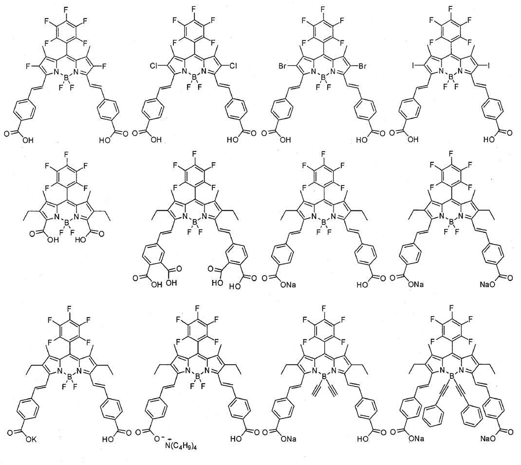
次に、光電変換素子及び色素増感太陽電池の主たる部材の好ましい態様について説明する。
Next, preferred embodiments of the main members of the photoelectric conversion element and the dye-sensitized solar cell will be described.
<導電性支持体>
導電性支持体は、導電性を有し、感光体層2等を支持できるものであれば特に限定されない。導電性支持体は、導電性を有する材料、例えば後述する金属で形成された導電性支持体1、又は、ガラス若しくはプラスチックの基板44とこの基板44の表面に成膜された透明導電膜43とを有する導電性支持体41が好ましい。 <Conductive support>
The conductive support is not particularly limited as long as it has conductivity and can support thephotoreceptor layer 2 and the like. The conductive support is made of a conductive material, for example, a conductive support 1 made of a metal described later, or a glass or plastic substrate 44 and a transparent conductive film 43 formed on the surface of the substrate 44. The electroconductive support body 41 which has is preferable.
導電性支持体は、導電性を有し、感光体層2等を支持できるものであれば特に限定されない。導電性支持体は、導電性を有する材料、例えば後述する金属で形成された導電性支持体1、又は、ガラス若しくはプラスチックの基板44とこの基板44の表面に成膜された透明導電膜43とを有する導電性支持体41が好ましい。 <Conductive support>
The conductive support is not particularly limited as long as it has conductivity and can support the
なかでも、基板44の表面に、金属酸化物の透明導電膜43を有する導電性支持体41が更に好ましい。このような導電性支持体41は、基板44の表面に導電性の金属酸化物を塗布して透明導電膜43を成膜することにより、得られる。プラスチックで形成された基板44としては、例えば、特開2001-291534号公報の段落番号0153に記載の透明ポリマーフィルムが挙げられる。また、基板44を形成する材料は、ガラス及びプラスチックの他にも、セラミック(特開2005-135902号公報)、導電性樹脂(特開2001-160425号公報)を用いることができる。金属酸化物としては、スズ酸化物(TO)が好ましく、インジウム-スズ酸化物(スズドープ酸化インジウム;ITO)、フッ素をドープした酸化スズ(FTO)等のフッ素ドープスズ酸化物が特に好ましい。このときの金属酸化物の塗布量は、基板44の表面積1m2当たり0.1~100gが好ましい。導電性支持体41を用いる場合、光は基板44側から入射させることが好ましい。
Among these, the conductive support 41 having the metal oxide transparent conductive film 43 on the surface of the substrate 44 is more preferable. Such a conductive support 41 is obtained by applying a conductive metal oxide to the surface of the substrate 44 to form a transparent conductive film 43. Examples of the substrate 44 made of plastic include a transparent polymer film described in paragraph No. 0153 of JP-A-2001-291534. In addition to glass and plastic, ceramic (Japanese Patent Laid-Open No. 2005-135902) or conductive resin (Japanese Patent Laid-Open No. 2001-160425) can be used as a material for forming the substrate 44. As the metal oxide, tin oxide (TO) is preferable, and fluorine-doped tin oxide such as indium-tin oxide (tin-doped indium oxide; ITO) and fluorine-doped tin oxide (FTO) is particularly preferable. The coating amount of the metal oxide at this time is preferably 0.1 to 100 g per 1 m 2 of the surface area of the substrate 44. When the conductive support 41 is used, light is preferably incident from the substrate 44 side.
導電性支持体1及び41は、実質的に透明であることが好ましい。「実質的に透明である」とは、光(波長300~1200nm)の透過率が10%以上であることを意味し、50%以上であることが好ましく、80%以上であることが特に好ましい。
導電性支持体1及び41の厚みは、特に限定されず、0.05μm~10mmであることが好ましく、0.1μm~5mmであることが更に好ましく、0.3μm~4mmであることが特に好ましい。
透明導電膜43を有する場合、透明導電膜43の厚みは、0.01~30μmであることが好ましく、0.03~25μmであることが更に好ましく、0.05~20μmであることが特に好ましい。 The conductive supports 1 and 41 are preferably substantially transparent. “Substantially transparent” means that the transmittance of light (wavelength 300 to 1200 nm) is 10% or more, preferably 50% or more, and particularly preferably 80% or more. .
The thickness of the conductive supports 1 and 41 is not particularly limited and is preferably 0.05 μm to 10 mm, more preferably 0.1 μm to 5 mm, and particularly preferably 0.3 μm to 4 mm. .
When the transparentconductive film 43 is provided, the thickness of the transparent conductive film 43 is preferably 0.01 to 30 μm, more preferably 0.03 to 25 μm, and particularly preferably 0.05 to 20 μm. .
導電性支持体1及び41の厚みは、特に限定されず、0.05μm~10mmであることが好ましく、0.1μm~5mmであることが更に好ましく、0.3μm~4mmであることが特に好ましい。
透明導電膜43を有する場合、透明導電膜43の厚みは、0.01~30μmであることが好ましく、0.03~25μmであることが更に好ましく、0.05~20μmであることが特に好ましい。 The conductive supports 1 and 41 are preferably substantially transparent. “Substantially transparent” means that the transmittance of light (
The thickness of the conductive supports 1 and 41 is not particularly limited and is preferably 0.05 μm to 10 mm, more preferably 0.1 μm to 5 mm, and particularly preferably 0.3 μm to 4 mm. .
When the transparent
導電性支持体1及び41は、その表面に、金属酸化物からなる金属酸化物被膜を有することが好ましい。金属酸化物としては、透明導電膜43を形成する上記金属酸化物、後述する半導体微粒子で挙げた金属酸化物を用いることができ、半導体微粒子で挙げた金属酸化物が好ましい。金属酸化物は、透明導電膜43を形成する上記金属酸化物又は半導電性微粒子で挙げた金属酸化物と同じ種類の金属酸化物であってもよく、異なる種類の金属酸化物であってもよい。この金属酸化物被膜は、通常、薄膜に形成され、例えば、0.01~100nmの厚みが好ましい。金属酸化物被膜の形成方法は、特に限定されず、後述する半導体微粒子が形成する層の形成方法と同様の方法が挙げられる。例えば、金属酸化物又はその前駆体(例えば、ハロゲン化物、アルコキシド)を含む液を塗布、加熱(焼成)することにより、金属酸化物被膜を形成できる。
The conductive supports 1 and 41 preferably have a metal oxide film made of a metal oxide on the surface thereof. As the metal oxide, the metal oxides that form the transparent conductive film 43 and the metal oxides exemplified in the semiconductor fine particles described later can be used, and the metal oxides exemplified in the semiconductor fine particles are preferable. The metal oxide may be the same type of metal oxide as that of the metal oxide or the semiconductive fine particles forming the transparent conductive film 43, or may be a different type of metal oxide. Good. This metal oxide film is usually formed as a thin film, and preferably has a thickness of 0.01 to 100 nm, for example. The formation method of a metal oxide film is not specifically limited, The method similar to the formation method of the layer which the semiconductor fine particle mentioned later forms is mentioned. For example, a metal oxide film can be formed by applying and heating (baking) a liquid containing a metal oxide or a precursor thereof (for example, a halide or an alkoxide).
導電性支持体1及び41は、表面に光マネージメント機能を有してもよい。例えば、表面に、特開2003-123859号公報に記載の高屈折膜及び低屈折率の酸化物膜を交互に積層した反射防止膜を有してもよく、特開2002-260746号公報に記載のライトガイド機能を有してもよい。
The conductive supports 1 and 41 may have a light management function on the surface. For example, an antireflection film in which high refractive films and low refractive index oxide films described in JP-A-2003-123859 are alternately laminated may be provided on the surface, as described in JP-A-2002-260746. The light guide function may be provided.
<感光体層>
感光体層は、上記色素21が担持された半導体微粒子22及び電解質を有していれば、その他の構成は特に限定されない。好ましくは、上記感光体層2及び上記感光体層42が挙げられる。 <Photoreceptor layer>
Other configurations are not particularly limited as long as the photoreceptor layer includes thesemiconductor fine particles 22 on which the dye 21 is supported and an electrolyte. Preferably, the photoreceptor layer 2 and the photoreceptor layer 42 are used.
感光体層は、上記色素21が担持された半導体微粒子22及び電解質を有していれば、その他の構成は特に限定されない。好ましくは、上記感光体層2及び上記感光体層42が挙げられる。 <Photoreceptor layer>
Other configurations are not particularly limited as long as the photoreceptor layer includes the
- 半導体微粒子(半導体微粒子が形成する層) -
半導体微粒子22は、好ましくは金属のカルコゲニド(例えば酸化物、硫化物、セレン化物等)又はペロブスカイト型結晶構造を有する化合物の微粒子である。金属のカルコゲニドとしては、好ましくはチタン、スズ、亜鉛、タングステン、ジルコニウム、ハフニウム、ストロンチウム、インジウム、セリウム、イットリウム、ランタン、バナジウム、ニオブ若しくはタンタルの酸化物、硫化カドミウム、セレン化カドミウム等が挙げられる。ペロブスカイト型結晶構造を有する化合物としては、好ましくはチタン酸ストロンチウム、チタン酸カルシウム等が挙げられる。これらのうち酸化チタン(チタニア)、酸化亜鉛、酸化スズ、酸化タングステンが特に好ましい。 -Semiconductor fine particles (layers formed by semiconductor fine particles)-
Thesemiconductor fine particles 22 are preferably fine particles of a metal chalcogenide (eg, oxide, sulfide, selenide, etc.) or a compound having a perovskite crystal structure. Preferred examples of the metal chalcogenide include titanium, tin, zinc, tungsten, zirconium, hafnium, strontium, indium, cerium, yttrium, lanthanum, vanadium, niobium or tantalum oxide, cadmium sulfide, and cadmium selenide. Preferred examples of the compound having a perovskite crystal structure include strontium titanate and calcium titanate. Of these, titanium oxide (titania), zinc oxide, tin oxide, and tungsten oxide are particularly preferable.
半導体微粒子22は、好ましくは金属のカルコゲニド(例えば酸化物、硫化物、セレン化物等)又はペロブスカイト型結晶構造を有する化合物の微粒子である。金属のカルコゲニドとしては、好ましくはチタン、スズ、亜鉛、タングステン、ジルコニウム、ハフニウム、ストロンチウム、インジウム、セリウム、イットリウム、ランタン、バナジウム、ニオブ若しくはタンタルの酸化物、硫化カドミウム、セレン化カドミウム等が挙げられる。ペロブスカイト型結晶構造を有する化合物としては、好ましくはチタン酸ストロンチウム、チタン酸カルシウム等が挙げられる。これらのうち酸化チタン(チタニア)、酸化亜鉛、酸化スズ、酸化タングステンが特に好ましい。 -Semiconductor fine particles (layers formed by semiconductor fine particles)-
The
チタニアの結晶構造としては、アナターゼ型、ブルッカイト型、又はルチル型が挙げられ、アナターゼ型、ブルッカイト型が好ましい。チタニアナノチューブ、ナノワイヤー、ナノロッドは、単独で、又は、チタニア微粒子に混合して、用いることができる。
Examples of the crystal structure of titania include anatase type, brookite type, and rutile type, and anatase type and brookite type are preferable. Titania nanotubes, nanowires, and nanorods can be used alone or mixed with titania fine particles.
半導体微粒子22の粒径は、投影面積を円に換算したときの直径を用いた平均粒径で1次粒子として0.001~1μm、分散物の平均粒径として0.01~100μmであることが好ましい。
The particle diameters of the semiconductor fine particles 22 are 0.001 to 1 μm as primary particles and 0.01 to 100 μm as the average particle diameter of the dispersion in terms of the average particle diameter when the projected area is converted into a circle. Is preferred.
半導体微粒子22は多くの色素21を吸着することができるように表面積の大きいものが好ましい。例えば半導体微粒子22を導電性支持体1又は41上に塗設した状態で、その表面積が投影面積に対して10倍以上であることが好ましく、100倍以上であることがより好ましい。この上限には特に制限はなく、通常5000倍程度である。一般に、半導体微粒子が形成する層(感光体層)の厚みが大きいほど単位面積当たりに担持できる色素21の量が増えるため光の吸収効率が高くなるが、発生した電子の拡散距離が増すため電荷再結合によるロスも大きくなる。
The semiconductor fine particles 22 preferably have a large surface area so that a large amount of the dye 21 can be adsorbed. For example, in a state where the semiconductor fine particles 22 are coated on the conductive support 1 or 41, the surface area thereof is preferably 10 times or more, more preferably 100 times or more the projected area. This upper limit is not particularly limited, and is usually about 5000 times. In general, the greater the thickness of the layer (photoreceptor layer) formed by semiconductor fine particles, the higher the amount of dye 21 that can be carried per unit area and the higher the light absorption efficiency, but the longer the diffusion distance of the generated electrons, the higher the charge. Loss due to recombination also increases.
半導体微粒子が形成する層の好ましい厚みは、光電変換素子の用途によって一義的なものではないが、典型的には0.1~100μmが好ましく、1~50μmがより好ましく、3~30μmが更に好ましい。
The preferred thickness of the layer formed by the semiconductor fine particles is not unambiguous depending on the use of the photoelectric conversion element, but is typically preferably 0.1 to 100 μm, more preferably 1 to 50 μm, still more preferably 3 to 30 μm. .
半導体微粒子22の層は、例えば、導電性支持体1又は41に半導体微粒子22を塗布した後に、100~800℃の温度で10分~10時間焼成して、形成できる。これにより、半導体微粒子同士を密着させることができ、好ましい。
半導体微粒子22を導電性支持体1又は41上に塗設する方法として、湿式法、乾式法、その他の方法が挙げられる。半導体微粒子22の、導電性支持体の表面積1m2当たりの塗布量は0.5~500g、更には5~100gが好ましい。
成膜温度は、導電性支持体1又は基板44の材料としてガラスを用いる場合、60~600℃が好ましい。 The layer of thesemiconductor fine particles 22 can be formed, for example, by applying the semiconductor fine particles 22 to the conductive support 1 or 41 and then baking at a temperature of 100 to 800 ° C. for 10 minutes to 10 hours. Thereby, the semiconductor fine particles can be brought into close contact with each other, which is preferable.
Examples of the method for coating thesemiconductor fine particles 22 on the conductive support 1 or 41 include a wet method, a dry method, and other methods. The coating amount of the semiconductor fine particles 22 per 1 m 2 of the surface area of the conductive support is preferably 0.5 to 500 g, more preferably 5 to 100 g.
The film forming temperature is preferably 60 to 600 ° C. when glass is used as the material of the conductive support 1 or the substrate 44.
半導体微粒子22を導電性支持体1又は41上に塗設する方法として、湿式法、乾式法、その他の方法が挙げられる。半導体微粒子22の、導電性支持体の表面積1m2当たりの塗布量は0.5~500g、更には5~100gが好ましい。
成膜温度は、導電性支持体1又は基板44の材料としてガラスを用いる場合、60~600℃が好ましい。 The layer of the
Examples of the method for coating the
The film forming temperature is preferably 60 to 600 ° C. when glass is used as the material of the conductive support 1 or the substrate 44.
- 光散乱層 -
本発明において、感光体層は光散乱層を有していてもよい。この光散乱層は、入射光を散乱させる機能を有する点で、半導体層45と異なる。
色素増感太陽電池20において、光散乱層46は、好ましくは、棒状又は板状の金属酸化物微粒子を含有する。光散乱層46に用いられる金属酸化物としては、例えば、上記半導体微粒子を形成する化合物として説明した上記金属のカルコゲニド(酸化物)が挙げられる。光散乱層46を設ける場合、光散乱層の厚みは感光体層42の厚みの10~50%とすることが好ましい。
光散乱層46は、特開2002-289274号公報に記載されている光散乱層が好ましく、特開2002-289274号公報の記載が、そのまま本明細書に好ましく取り込まれる。 -Light scattering layer-
In the present invention, the photoreceptor layer may have a light scattering layer. This light scattering layer is different from thesemiconductor layer 45 in that it has a function of scattering incident light.
In the dye-sensitizedsolar cell 20, the light scattering layer 46 preferably contains rod-like or plate-like metal oxide fine particles. Examples of the metal oxide used in the light scattering layer 46 include the chalcogenide (oxide) of the metal described as the compound that forms the semiconductor fine particles. When the light scattering layer 46 is provided, the thickness of the light scattering layer is preferably 10 to 50% of the thickness of the photoreceptor layer 42.
The light scattering layer 46 is preferably a light scattering layer described in JP-A No. 2002-289274, and the description of JP-A No. 2002-289274 is preferably incorporated in this specification as it is.
本発明において、感光体層は光散乱層を有していてもよい。この光散乱層は、入射光を散乱させる機能を有する点で、半導体層45と異なる。
色素増感太陽電池20において、光散乱層46は、好ましくは、棒状又は板状の金属酸化物微粒子を含有する。光散乱層46に用いられる金属酸化物としては、例えば、上記半導体微粒子を形成する化合物として説明した上記金属のカルコゲニド(酸化物)が挙げられる。光散乱層46を設ける場合、光散乱層の厚みは感光体層42の厚みの10~50%とすることが好ましい。
光散乱層46は、特開2002-289274号公報に記載されている光散乱層が好ましく、特開2002-289274号公報の記載が、そのまま本明細書に好ましく取り込まれる。 -Light scattering layer-
In the present invention, the photoreceptor layer may have a light scattering layer. This light scattering layer is different from the
In the dye-sensitized
The light scattering layer 46 is preferably a light scattering layer described in JP-A No. 2002-289274, and the description of JP-A No. 2002-289274 is preferably incorporated in this specification as it is.
- 金属酸化物被膜 -
本発明において、感光体層を形成する半導体微粒子(半導体層45及び光散乱層46を形成するものを含む)は、その表面に金属酸化物被膜を有することが好ましい。金属酸化物被膜を形成する金属酸化物としては、上記半導体微粒子で挙げた金属酸化物を用いることができ、上記半導体微粒子と同じ種類の金属酸化物であっても異なる種類の金属酸化物であってもよい。この金属酸化物被膜は、通常、薄膜に形成され、例えば0.1~100nmの厚みが好ましい。本発明において、半導体微粒子が金属酸化物被膜を有する場合、ジピロメテン錯体化合物は金属酸化物被膜を介して半導体微粒子に吸着される。金属酸化物被膜の形成方法は上記した通りである。
本発明において、導電性支持体及び半導体微粒子の表面それぞれに金属酸化物被膜を有することもできる。この場合、それぞれの金属酸化物被膜は同じ種類の金属酸化物で形成されていてもよく、異なる種類の金属酸化物で形成されていてもよい。 -Metal oxide coating-
In the present invention, the semiconductor fine particles (including those forming thesemiconductor layer 45 and the light scattering layer 46) forming the photoreceptor layer preferably have a metal oxide film on the surface thereof. As the metal oxide for forming the metal oxide film, the metal oxides mentioned above for the semiconductor fine particles can be used. May be. This metal oxide film is usually formed as a thin film, and preferably has a thickness of 0.1 to 100 nm, for example. In the present invention, when the semiconductor fine particles have a metal oxide film, the dipyrromethene complex compound is adsorbed on the semiconductor fine particles through the metal oxide film. The method for forming the metal oxide film is as described above.
In the present invention, each of the surfaces of the conductive support and the semiconductor fine particles may have a metal oxide film. In this case, each metal oxide film may be formed of the same type of metal oxide or may be formed of different types of metal oxide.
本発明において、感光体層を形成する半導体微粒子(半導体層45及び光散乱層46を形成するものを含む)は、その表面に金属酸化物被膜を有することが好ましい。金属酸化物被膜を形成する金属酸化物としては、上記半導体微粒子で挙げた金属酸化物を用いることができ、上記半導体微粒子と同じ種類の金属酸化物であっても異なる種類の金属酸化物であってもよい。この金属酸化物被膜は、通常、薄膜に形成され、例えば0.1~100nmの厚みが好ましい。本発明において、半導体微粒子が金属酸化物被膜を有する場合、ジピロメテン錯体化合物は金属酸化物被膜を介して半導体微粒子に吸着される。金属酸化物被膜の形成方法は上記した通りである。
本発明において、導電性支持体及び半導体微粒子の表面それぞれに金属酸化物被膜を有することもできる。この場合、それぞれの金属酸化物被膜は同じ種類の金属酸化物で形成されていてもよく、異なる種類の金属酸化物で形成されていてもよい。 -Metal oxide coating-
In the present invention, the semiconductor fine particles (including those forming the
In the present invention, each of the surfaces of the conductive support and the semiconductor fine particles may have a metal oxide film. In this case, each metal oxide film may be formed of the same type of metal oxide or may be formed of different types of metal oxide.
- 色素 -
光電変換素子10及び色素増感太陽電池20においては、増感色素として、上記式(1)で表されるジピロメテン錯体色素を担持している。式(1)で表されるジピロメテン錯体色素は上記の通りである。 -Dye-
In thephotoelectric conversion element 10 and the dye-sensitized solar cell 20, the dipyrromethene complex dye represented by the above formula (1) is supported as the sensitizing dye. The dipyrromethene complex dye represented by the formula (1) is as described above.
光電変換素子10及び色素増感太陽電池20においては、増感色素として、上記式(1)で表されるジピロメテン錯体色素を担持している。式(1)で表されるジピロメテン錯体色素は上記の通りである。 -Dye-
In the
半導体微粒子は、上述のジピロメテン錯体色素と併せて、他の色素を担持していてもよい。本発明において、ジピロメテン錯体色素と併用できる色素としては、特に限定されず、Ru錯体色素、スクアリリウムシアニン色素、有機色素、ポルフィリン色素、フタロシアニン色素等が挙げられる。併用できる色素としては、Ru錯体色素、スクアリリウムシアニン色素、又は有機色素が好ましい。
The semiconductor fine particles may carry other dyes together with the above-described dipyrromethene complex dye. In the present invention, the dye that can be used in combination with the dipyrromethene complex dye is not particularly limited, and examples thereof include a Ru complex dye, a squarylium cyanine dye, an organic dye, a porphyrin dye, and a phthalocyanine dye. The dye that can be used in combination is preferably a Ru complex dye, a squarylium cyanine dye, or an organic dye.
色素の使用量は、一概には決定できないが、導電性支持体1又は41の表面積1m2当たり0.01~100ミリモルが好ましく、より好ましくは0.1~50ミリモル、特に好ましくは1~10ミリモルである。また、色素の半導体微粒子に対する吸着量は1gの半導体微粒子に対して0.001~1ミリモルが好ましく、より好ましくは0.1~0.5ミリモルである。このような色素量とすることによって、半導体微粒子における増感効果が十分に得られる。
The amount of the dye used cannot be generally determined, but is preferably 0.01 to 100 mmol, more preferably 0.1 to 50 mmol, particularly preferably 1 to 10 per 1 m 2 of the surface area of the conductive support 1 or 41. Millimolar. Further, the adsorption amount of the dye to the semiconductor fine particles is preferably 0.001 to 1 mmol, more preferably 0.1 to 0.5 mmol, with respect to 1 g of the semiconductor fine particles. By using such a dye amount, the sensitizing effect in the semiconductor fine particles can be sufficiently obtained.
式(1)で表されるジピロメテン錯体色素と他の色素を併用する場合、式(1)で表されるジピロメテン錯体色素の質量/他の色素の質量の比は、95/5~10/90が好ましく、95/5~50/50がより好ましく、95/5~60/40が更に好ましく、95/5~65/35が特に好ましく、95/5~70/30が最も好ましい。
When the dipyrromethene complex dye represented by formula (1) is used in combination with another dye, the ratio of the mass of the dipyrromethene complex dye represented by formula (1) / the mass of the other dye is 95/5 to 10/90. Is preferred, 95/5 to 50/50 is more preferred, 95/5 to 60/40 is still more preferred, 95/5 to 65/35 is particularly preferred, and 95/5 to 70/30 is most preferred.
- 電解質 -
感光体層は電解質を含む。感光体層に含まれる電解質は、後述する電荷移動体層が有する電解質と同義であり、好ましいものも同じである。感光体層に含まれる電解質は、電荷移動体層が有する電解質と同種でも異種であってもよく、同種であることが好ましい。 - Electrolytes -
The photoreceptor layer contains an electrolyte. The electrolyte contained in the photoreceptor layer is synonymous with the electrolyte that the charge transfer layer described later has, and preferred ones are also the same. The electrolyte contained in the photoreceptor layer may be the same as or different from the electrolyte of the charge transfer layer, and is preferably the same.
- 共吸着剤 -
本発明において、半導体微粒子は、式(1)で表されるジピロメテン錯体色素又は必要により併用する色素とともに、共吸着剤を担持していることが好ましい。このような共吸着剤としては酸性基(好ましくは、カルボキシ基又はその塩)を1つ以上有する共吸着剤が好ましく、脂肪酸やステロイド骨格を有する化合物が挙げられる。
脂肪酸は、飽和脂肪酸でも不飽和脂肪酸でもよく、例えば、ブタン酸、ヘキサン酸、オクタン酸、デカン酸、ヘキサデカン酸、ドデカン酸、パルミチン酸、ステアリン酸、オレイン酸、リノール酸、リノレン酸等が挙げられる。
ステロイド骨格を有する化合物として、コール酸、グリココール酸、ケノデオキシコール酸、ヒオコール酸、デオキシコール酸、リトコール酸、ウルソデオキシコール酸等が挙げられる。好ましくはコール酸、デオキシコール酸、ケノデオキシコール酸であり、更に好ましくはケノデオキシコール酸である。 -Coadsorbent-
In the present invention, it is preferable that the semiconductor fine particles carry a co-adsorbent together with the dipyrromethene complex dye represented by the formula (1) or a dye used in combination if necessary. As such a co-adsorbent, a co-adsorbent having at least one acidic group (preferably a carboxy group or a salt thereof) is preferable, and examples thereof include a compound having a fatty acid or a steroid skeleton.
The fatty acid may be a saturated fatty acid or an unsaturated fatty acid, and examples thereof include butanoic acid, hexanoic acid, octanoic acid, decanoic acid, hexadecanoic acid, dodecanoic acid, palmitic acid, stearic acid, oleic acid, linoleic acid, and linolenic acid. .
Examples of the compound having a steroid skeleton include cholic acid, glycocholic acid, chenodeoxycholic acid, hyocholic acid, deoxycholic acid, lithocholic acid, ursodeoxycholic acid and the like. Preferred are cholic acid, deoxycholic acid and chenodeoxycholic acid, and more preferred are chenodeoxycholic acid.
好ましい共吸着剤として、特開2014-82187号公報の段落番号0125~0129に記載の式(CA)で表される化合物が挙げられ、特開2014-82187号公報の段落番号0125~0129の記載が、そのまま本明細書に好ましく取り込まれる。
Preferable coadsorbents include compounds represented by the formula (CA) described in paragraphs 0125 to 0129 of JP 2014-82187 A, and descriptions of paragraphs 0125 to 0129 of JP 2014-82187 A. Are preferably incorporated in the present specification as they are.
上記共吸着剤は、半導体微粒子に吸着させることにより、ジピロメテン錯体色素の非効率な会合を抑制する効果及び半導体微粒子表面から電解質中のレドックス系への逆電子移動を防止する効果がある。共吸着剤の使用量は、特に限定されず、上記の作用を効果的に発現させる観点から、上記ジピロメテン錯体色素1モルに対して、好ましくは0.1~200モル、更に好ましくは1~100モル、特に好ましくは2~50モルである。
The co-adsorbent has an effect of suppressing inefficient association of the dipyrromethene complex dye and an effect of preventing reverse electron transfer from the surface of the semiconductor fine particle to the redox system in the electrolyte by being adsorbed on the semiconductor fine particle. The amount of the co-adsorbent used is not particularly limited, and is preferably 0.1 to 200 mol, more preferably 1 to 100, with respect to 1 mol of the dipyrromethene complex dye from the viewpoint of effectively expressing the above action. Mol, particularly preferably 2 to 50 mol.
- アミン化合物 -
色素を半導体微粒子に担持させた後に、アミン化合物を用いて半導体微粒子の表面を処理してもよい。好ましいアミン化合物としてピリジン化合物(例えば4-t-ブチルピリジン、ポリビニルピリジン)等が挙げられる。これらは液体の場合はそのまま用いてもよいし、有機溶媒に溶解して用いてもよい。 -Amine compounds-
After the dye is supported on the semiconductor fine particles, the surface of the semiconductor fine particles may be treated with an amine compound. Preferable amine compounds include pyridine compounds (for example, 4-t-butylpyridine, polyvinylpyridine) and the like. In the case of a liquid, these may be used as they are, or may be used after being dissolved in an organic solvent.
<電荷移動体層>
電荷移動体層3及び47は、色素21の酸化体に電子を補充する機能を有する層であり、受光電極5又は40と、対極4又は48との間に設けられる。
電荷移動体層3及び47は電解質を含む。ここで、「電荷移動体層が電解質を含む」とは、電荷移動体層が電解質のみからなる態様、及び、電解質と電解質以外の物質を含有する態様の、両態様を含む意味である。
電荷移動体層3及び47は、固体状、液体状、ゲル状又はこれら混合状態のいずれであってもよい。 <Charge transfer layer>
The charge transfer body layers 3 and 47 are layers having a function of replenishing electrons to the oxidant of thedye 21, and are provided between the light receiving electrode 5 or 40 and the counter electrode 4 or 48.
The charge transfer body layers 3 and 47 contain an electrolyte. Here, “the charge transfer layer includes an electrolyte” means to include both of an embodiment in which the charge transfer layer is composed only of an electrolyte and an embodiment that contains an electrolyte and a substance other than the electrolyte.
Thecharge transfer layer 3 and 47 may be solid, liquid, gel, or a mixed state thereof.
電荷移動体層3及び47は、色素21の酸化体に電子を補充する機能を有する層であり、受光電極5又は40と、対極4又は48との間に設けられる。
電荷移動体層3及び47は電解質を含む。ここで、「電荷移動体層が電解質を含む」とは、電荷移動体層が電解質のみからなる態様、及び、電解質と電解質以外の物質を含有する態様の、両態様を含む意味である。
電荷移動体層3及び47は、固体状、液体状、ゲル状又はこれら混合状態のいずれであってもよい。 <Charge transfer layer>
The charge transfer body layers 3 and 47 are layers having a function of replenishing electrons to the oxidant of the
The charge transfer body layers 3 and 47 contain an electrolyte. Here, “the charge transfer layer includes an electrolyte” means to include both of an embodiment in which the charge transfer layer is composed only of an electrolyte and an embodiment that contains an electrolyte and a substance other than the electrolyte.
The
- 電解質 -
電解質の例としては、酸化還元対を有機溶媒に溶解した液体電解質、酸化還元対を含有する溶融塩及び酸化還元対を有機溶媒に溶解した液体をポリマーマトリクスに含浸したいわゆるゲル電解質等が挙げられる。なかでも、液体電解質が光電変換効率の点で好ましい。 - Electrolytes -
Examples of the electrolyte include a liquid electrolyte in which a redox couple is dissolved in an organic solvent, a molten salt containing a redox couple, and a so-called gel electrolyte in which a polymer matrix is impregnated with a liquid in which a redox couple is dissolved in an organic solvent. . Especially, a liquid electrolyte is preferable at the point of photoelectric conversion efficiency.
酸化還元対として、例えばヨウ素とヨウ化物(ヨウ化物塩、ヨウ化イオン性液体が好ましく、ヨウ化リチウム、ヨウ化テトラブチルアンモニウム、ヨウ化テトラプロピルアンモニウム、ヨウ化メチルプロピルイミダゾリウムが好ましい)との組み合わせ、アルキルビオローゲン(例えばメチルビオローゲンクロリド、ヘキシルビオローゲンブロミド、ベンジルビオローゲンテトラフルオロボレート)とその還元体との組み合わせ、ポリヒドロキシベンゼン(例えばハイドロキノン、ナフトハイドロキノン等)とその酸化体との組み合わせ、2価と3価の鉄錯体の組み合わせ(例えば赤血塩と黄血塩の組み合わせ)、2価と3価のコバルト錯体の組み合わせ等が挙げられる。これらのうち、ヨウ素とヨウ化物との組み合わせ、又は2価と3価のコバルト錯体の組み合わせが好ましく、ヨウ素とヨウ化物との組み合わせが特に好ましい。
As an oxidation-reduction pair, for example, iodine and iodide (iodide salt, ionic liquid is preferable, lithium iodide, tetrabutylammonium iodide, tetrapropylammonium iodide, methylpropylimidazolium iodide are preferable) A combination of an alkyl viologen (eg, methyl viologen chloride, hexyl viologen bromide, benzyl viologen tetrafluoroborate) and a reduced form thereof, a combination of polyhydroxybenzene (eg, hydroquinone, naphthohydroquinone, etc.) and an oxidized form thereof, A combination of trivalent iron complexes (for example, a combination of red blood salt and yellow blood salt), a combination of divalent and trivalent cobalt complexes, and the like. Among these, a combination of iodine and iodide or a combination of divalent and trivalent cobalt complexes is preferable, and a combination of iodine and iodide is particularly preferable.
上記コバルト錯体は、特開2014-82189号公報の段落番号0144~0156に記載の式(CC)で表される錯体が好ましく、特開2014-82189号公報の段落番号0144~0156の記載が、そのまま本明細書に好ましく取り込まれる。
The cobalt complex is preferably a complex represented by the formula (CC) described in paragraphs 0144 to 0156 of JP2014-82189A, and described in paragraphs 0144 to 0156 of JP2014-82189A. It is preferably incorporated in the present specification as it is.
電解質として、ヨウ素とヨウ化物との組み合わせを用いる場合、5員環又は6員環の含窒素芳香族カチオンのヨウ素塩を更に併用するのが好ましい。
When a combination of iodine and iodide is used as the electrolyte, it is preferable to further use an iodine salt of a 5-membered or 6-membered nitrogen-containing aromatic cation.
液体電解質及びゲル電解質に用いる有機溶媒としては、特に限定されず、非プロトン性の極性溶媒(例えばアセトニトリル、炭酸プロピレン、炭酸エチレン、ジメチルホルムアミド、ジメチルスルホキシド、スルホラン、1,3-ジメチルイミダゾリノン、3-メチルオキサゾリジノン等)が好ましい。
特に、液体電解質に用いる有機溶媒としては、ニトリル化合物、エーテル化合物、エステル化合物等が好ましく、ニトリル化合物がより好ましく、アセトニトリル、メトキシプロピオニトリルが特に好ましい。 The organic solvent used for the liquid electrolyte and the gel electrolyte is not particularly limited, and is an aprotic polar solvent (for example, acetonitrile, propylene carbonate, ethylene carbonate, dimethylformamide, dimethyl sulfoxide, sulfolane, 1,3-dimethylimidazolinone, 3 -Methyloxazolidinone etc.) are preferred.
In particular, the organic solvent used for the liquid electrolyte is preferably a nitrile compound, an ether compound, an ester compound, more preferably a nitrile compound, and particularly preferably acetonitrile or methoxypropionitrile.
溶融塩やゲル電解質としては、特開2014-139931号公報の段落番号0205及び段落番号0208~0213に記載のものが好ましく、特開2014-139931号公報の段落番号0205及び段落番号0208~0213の記載が、そのまま本明細書に好ましく取り込まれる。
As the molten salt or gel electrolyte, those described in paragraph No. 0205 and paragraph Nos. 0208-0213 of JP-A No. 2014-139931 are preferable, and those of paragraph No. 0205 and paragraph Nos. 0208-0213 of JP-A No. 2014-139931 are preferable. The description is preferably incorporated herein as it is.
電解質は、添加物として、4-t-ブチルピリジン等のピリジン化合物のほか、アミノピリジン化合物、ベンズイミダゾール化合物、アミノトリアゾール化合物及びアミノチアゾール化合物、イミダゾール化合物、アミノトリアジン化合物、尿素化合物、アミド化合物、ピリミジン化合物又は窒素を含まない複素環を含有していてもよい。
In addition to pyridine compounds such as 4-t-butylpyridine, electrolytes include aminopyridine compounds, benzimidazole compounds, aminotriazole compounds and aminothiazole compounds, imidazole compounds, aminotriazine compounds, urea compounds, amide compounds, and pyrimidines as additives. It may contain a compound or a nitrogen-free heterocycle.
また、光電変換効率を向上させるために、電解液の水分を制御する方法をとってもよい。水分を制御する好ましい方法としては、濃度を制御する方法や脱水剤を共存させる方法を挙げることができる。電解液の水分含有量(含有率)を0~0.1質量%に調整することが好ましい。
ヨウ素は、ヨウ素とシクロデキストリンとの包接化合物として使用することもできる。また環状アミジンを用いてもよく、酸化防止剤、加水分解防止剤、分解防止剤、ヨウ化亜鉛を加えてもよい。 Moreover, in order to improve photoelectric conversion efficiency, you may take the method of controlling the water | moisture content of electrolyte solution. Preferred methods for controlling moisture include a method for controlling the concentration and a method in which a dehydrating agent is allowed to coexist. It is preferable to adjust the water content (content ratio) of the electrolytic solution to 0 to 0.1% by mass.
Iodine can also be used as an inclusion compound of iodine and cyclodextrin. Cyclic amidine may be used, and an antioxidant, hydrolysis inhibitor, decomposition inhibitor, and zinc iodide may be added.
上述の液体電解質及び擬固体電解質の代わりに、p型半導体又はホール輸送材料等の固体電荷輸送材料、例えば、CuI若しくはCuNCS等を用いることができる。また、Nature,vol.486,p.487(2012)等に記載の電解質を用いてもよい。固体電荷輸送材料として有機ホール輸送材料を用いてもよい。有機ホール輸送材料は、溶液塗布可能で固体状になる正孔輸送材料が好ましい。
正孔輸送材料としては、低分子化合物又は高分子化合物が挙げられ、トリアリールアミン化合物、ポリチオフェン化合物(例えば、ポリ(3-ヘキシルチオフェン-2,5-ジイル)、ポリエチレンジオキシチオフェン(PEDOT))、ポリフェニレンビニレン化合物、ポリアニリン化合物、ポリピロール化合物、又は、これらの共重合体が挙げられる。 Instead of the above-mentioned liquid electrolyte and quasi-solid electrolyte, a solid charge transport material such as a p-type semiconductor or a hole transport material, for example, CuI or CuNCS can be used. Also, Nature, vol. 486, p. The electrolyte described in 487 (2012) or the like may be used. An organic hole transport material may be used as the solid charge transport material. The organic hole transport material is preferably a hole transport material that can be applied by solution and becomes a solid.
Examples of the hole transporting material include a low molecular compound or a high molecular compound, such as a triarylamine compound, a polythiophene compound (for example, poly (3-hexylthiophene-2,5-diyl), polyethylenedioxythiophene (PEDOT)). , A polyphenylene vinylene compound, a polyaniline compound, a polypyrrole compound, or a copolymer thereof.
トリアリールアミン化合物は、低分子化合物であっても高分子化合物であってもよい。
トリアリールアミン化合物としては、下記式(HT-1)で表される化合物が挙げられる。 The triarylamine compound may be a low molecular compound or a high molecular compound.
Examples of the triarylamine compound include a compound represented by the following formula (HT-1).
トリアリールアミン化合物としては、下記式(HT-1)で表される化合物が挙げられる。 The triarylamine compound may be a low molecular compound or a high molecular compound.
Examples of the triarylamine compound include a compound represented by the following formula (HT-1).

式(HT-1)中、RA1~RA15は、それぞれ、水素原子又は置換基を表す。
RA1~RA15として採りうる置換基としては、上記置換基群Tから選ばれる置換基が挙げられ、隣り合う置換基同士が単結合又は連結基を介して結合して環を形成してもよい。耐熱性及び耐久性の観点から、RA1~RA5の少なくとも一つがアリール基であることが好ましく、RA1~RA5の少なくとも一つとRA6~RA10の少なくとも一つがアリール基であることがより好ましい。 In formula (HT-1), R A1 to R A15 each represent a hydrogen atom or a substituent.
Examples of the substituent that can be adopted as R A1 to R A15 include a substituent selected from the above substituent group T. Even if adjacent substituents are bonded via a single bond or a linking group to form a ring. Good. From the viewpoint of heat resistance and durability, that at least one of R A1 ~ Preferably, at least one of R A5 is an aryl group, R A1 ~ least one and R a R A5 A6 ~ R A10 is an aryl group More preferred.
トリアリールアミン化合物においては、光電変換素子の製造バラツキを抑制する観点から、分子量が400以上1200以下であることが好ましく、550以上1100以下であることがより好ましく、600以上1000以下であることが更に好ましく、600以上900以下であることが特に好ましい。
In the triarylamine compound, the molecular weight is preferably 400 or more, 1200 or less, more preferably 550 or more and 1100 or less, and more preferably 600 or more and 1000 or less from the viewpoint of suppressing the manufacturing variation of the photoelectric conversion element. More preferably, it is 600 or more and 900 or less.
上記式(HT-1)で表される化合物の具体例としては、2,2’,7,7’-テトラキス-(N,N-ジ-p-メトキシフェニルアミン)-9,9-スピロビフルオレン(Spiro-OMeTAD)、下記(HTL-1)~(HTL-14)で表される化合物等が挙げられるが、本発明はこれらに限定されない。
Specific examples of the compound represented by the above formula (HT-1) include 2,2 ′, 7,7′-tetrakis- (N, N-di-p-methoxyphenylamine) -9,9-spirobi Examples include fluorene (Spiro-OMeTAD) and the compounds represented by the following (HTL-1) to (HTL-14), but the present invention is not limited thereto.


上記有機ホール輸送材料としては、2,2’,7,7’-テトラキス-(N,N-ジ-p-メトキシフェニルアミン)-9,9-スピロビフルオレン、ポリ(3-ヘキシルチオフェン-2,5-ジイル)、4-(ジエチルアミノ)ベンゾアルデヒド ジフェニルヒドラゾン、又は、ポリエチレンジオキシチオフェン等が好ましい。
Examples of the organic hole transport material include 2,2 ′, 7,7′-tetrakis- (N, N-di-p-methoxyphenylamine) -9,9-spirobifluorene, poly (3-hexylthiophene-2 , 5-diyl), 4- (diethylamino) benzaldehyde, diphenylhydrazone, or polyethylenedioxythiophene.
酸化還元対は、電子のキャリアになるので、ある程度の濃度で含有するのが好ましい。好ましい濃度としては合計で0.01モル/L以上であり、より好ましくは0.1モル/L以上であり、特に好ましくは0.3モル/L以上である。この場合の上限は特に制限はなく、通常5モル/L程度である。
Since the redox couple becomes an electron carrier, it is preferably contained at a certain concentration. A preferable concentration is 0.01 mol / L or more in total, more preferably 0.1 mol / L or more, and particularly preferably 0.3 mol / L or more. The upper limit in this case is not particularly limited, and is usually about 5 mol / L.
<対極>
対極4及び48は、色素増感太陽電池の正極として働くものであることが好ましい。対極4及び48は、通常、上記導電性支持体1又は41と同じ構成とすることもできるが、強度が十分に保たれるような構成では基板44は必ずしも必要でない。
対極を形成する金属としては、例えば、白金(Pt)、金(Au)、ニッケル(Ni)、銅(Cu)、銀(Ag)、インジウム(In)、ルテニウム(Ru)、パラジウム(Pd)、ロジウム(Rh)、イリジウム(Ir)、オスニウム(Os)、アルミニウム(Al)等が挙げられる。
対極4及び48の構造としては、集電効果が高い構造が好ましい。感光体層2及び42に光が到達するためには、上記導電性支持体1又は41と対極4又は48との少なくとも一方は実質的に透明でなければならない。本発明の色素増感太陽電池においては、導電性支持体1又は41が透明であって、太陽光を導電性支持体1又は41側から入射させるのが好ましい。この場合、対極4及び48は光を反射する性質を有することが更に好ましい。色素増感太陽電池の対極4及び48としては、金属若しくは導電性の酸化物を蒸着したガラス又はプラスチックが好ましく、白金を蒸着したガラスが特に好ましい。
対極の膜厚は、特に限定されず、0.01~100μmが好ましく、0.01~10μmが更に好ましく、0.01~1μmが特に好ましい。 <Counter electrode>
Thecounter electrodes 4 and 48 preferably function as positive electrodes of the dye-sensitized solar cell. The counter electrodes 4 and 48 can usually have the same configuration as that of the conductive support 1 or 41, but the substrate 44 is not necessarily required in a configuration in which the strength is sufficiently maintained.
Examples of the metal forming the counter electrode include platinum (Pt), gold (Au), nickel (Ni), copper (Cu), silver (Ag), indium (In), ruthenium (Ru), palladium (Pd), Examples include rhodium (Rh), iridium (Ir), osmium (Os), and aluminum (Al).
The structure of thecounter electrodes 4 and 48 is preferably a structure having a high current collecting effect. In order for light to reach the photoreceptor layers 2 and 42, at least one of the conductive support 1 or 41 and the counter electrode 4 or 48 must be substantially transparent. In the dye-sensitized solar cell of the present invention, it is preferable that the conductive support 1 or 41 is transparent, and sunlight is incident from the conductive support 1 or 41 side. In this case, it is more preferable that the counter electrodes 4 and 48 have a property of reflecting light. As the counter electrodes 4 and 48 of the dye-sensitized solar cell, glass or plastic on which a metal or a conductive oxide is vapor-deposited is preferable, and glass on which platinum is vapor-deposited is particularly preferable.
The thickness of the counter electrode is not particularly limited, but is preferably 0.01 to 100 μm, more preferably 0.01 to 10 μm, and particularly preferably 0.01 to 1 μm.
対極4及び48は、色素増感太陽電池の正極として働くものであることが好ましい。対極4及び48は、通常、上記導電性支持体1又は41と同じ構成とすることもできるが、強度が十分に保たれるような構成では基板44は必ずしも必要でない。
対極を形成する金属としては、例えば、白金(Pt)、金(Au)、ニッケル(Ni)、銅(Cu)、銀(Ag)、インジウム(In)、ルテニウム(Ru)、パラジウム(Pd)、ロジウム(Rh)、イリジウム(Ir)、オスニウム(Os)、アルミニウム(Al)等が挙げられる。
対極4及び48の構造としては、集電効果が高い構造が好ましい。感光体層2及び42に光が到達するためには、上記導電性支持体1又は41と対極4又は48との少なくとも一方は実質的に透明でなければならない。本発明の色素増感太陽電池においては、導電性支持体1又は41が透明であって、太陽光を導電性支持体1又は41側から入射させるのが好ましい。この場合、対極4及び48は光を反射する性質を有することが更に好ましい。色素増感太陽電池の対極4及び48としては、金属若しくは導電性の酸化物を蒸着したガラス又はプラスチックが好ましく、白金を蒸着したガラスが特に好ましい。
対極の膜厚は、特に限定されず、0.01~100μmが好ましく、0.01~10μmが更に好ましく、0.01~1μmが特に好ましい。 <Counter electrode>
The
Examples of the metal forming the counter electrode include platinum (Pt), gold (Au), nickel (Ni), copper (Cu), silver (Ag), indium (In), ruthenium (Ru), palladium (Pd), Examples include rhodium (Rh), iridium (Ir), osmium (Os), and aluminum (Al).
The structure of the
The thickness of the counter electrode is not particularly limited, but is preferably 0.01 to 100 μm, more preferably 0.01 to 10 μm, and particularly preferably 0.01 to 1 μm.
<その他の構成>
導電性支持体1又は41と感光体層2又は42との間には、感光体層2又は42が含む電解質と導電性支持体1又は41が直接接触することによる逆電流を防止するため、短絡防止層を形成することが好ましい。
また、受光電極5又は40と対極4又は48の接触を防ぐために、スペーサーS(図2参照)及び/又はセパレータを用いることが好ましい。
更に、光電変換素子又は色素増感太陽電池において、構成物の蒸散等を防止するために、光電変換素子又は色素増感太陽電池の側面をポリマーや接着剤等で密封することが好ましい。 <Other configurations>
Between the conductive support 1 or 41 and thephotoreceptor layer 2 or 42, in order to prevent reverse current due to direct contact between the electrolyte contained in the photoreceptor layer 2 or 42 and the conductive support 1 or 41, It is preferable to form a short-circuit prevention layer.
In order to prevent contact between thelight receiving electrode 5 or 40 and the counter electrode 4 or 48, it is preferable to use a spacer S (see FIG. 2) and / or a separator.
Furthermore, in the photoelectric conversion element or the dye-sensitized solar cell, it is preferable to seal the side surface of the photoelectric conversion element or the dye-sensitized solar cell with a polymer, an adhesive, or the like in order to prevent transpiration of the constituents.
導電性支持体1又は41と感光体層2又は42との間には、感光体層2又は42が含む電解質と導電性支持体1又は41が直接接触することによる逆電流を防止するため、短絡防止層を形成することが好ましい。
また、受光電極5又は40と対極4又は48の接触を防ぐために、スペーサーS(図2参照)及び/又はセパレータを用いることが好ましい。
更に、光電変換素子又は色素増感太陽電池において、構成物の蒸散等を防止するために、光電変換素子又は色素増感太陽電池の側面をポリマーや接着剤等で密封することが好ましい。 <Other configurations>
Between the conductive support 1 or 41 and the
In order to prevent contact between the
Furthermore, in the photoelectric conversion element or the dye-sensitized solar cell, it is preferable to seal the side surface of the photoelectric conversion element or the dye-sensitized solar cell with a polymer, an adhesive, or the like in order to prevent transpiration of the constituents.
本発明の色素増感太陽電池は、上述の光電変換素子を用いて構成される。例えば、図1に示されるように、光電変換素子の導電性支持体と対極とを外部回路6で接続して色素増感太陽電池とすることができる。外部回路6は、公知のものを特に制限されることなく、用いることができる。
The dye-sensitized solar cell of the present invention is configured using the above-described photoelectric conversion element. For example, as shown in FIG. 1, a dye-sensitized solar cell can be obtained by connecting a conductive support of a photoelectric conversion element and a counter electrode with an external circuit 6. As the external circuit 6, a known circuit can be used without particular limitation.
光電変換素子及び色素増感太陽電池は、上記式(1)で表されるジピロメテン錯体化合物を担持している。これにより、高い光電変換効率を示す。
このジピロメテン錯体化合物は、通常、黄色~青色を呈する。そのため、各層の材質にもよるが、導電性支持体又は対極が実質的に透明である場合、光電変換素子及び色素増感太陽電池は黄色~青色を呈し、意匠性にも優れる。 The photoelectric conversion element and the dye-sensitized solar cell carry the dipyrromethene complex compound represented by the above formula (1). Thereby, high photoelectric conversion efficiency is shown.
This dipyrromethene complex compound usually exhibits yellow to blue color. Therefore, although depending on the material of each layer, when the conductive support or the counter electrode is substantially transparent, the photoelectric conversion element and the dye-sensitized solar cell exhibit yellow to blue color and are excellent in design.
[光電変換素子及び色素増感太陽電池の製造方法]
本発明の光電変換素子及び色素増感太陽電池は、上記式(1)で表されるジピロメテン錯体化合物及び溶媒を含有する色素溶液を用いて、製造することが好ましい。 [Method for producing photoelectric conversion element and dye-sensitized solar cell]
The photoelectric conversion element and the dye-sensitized solar cell of the present invention are preferably produced using a dye solution containing a dipyrromethene complex compound represented by the above formula (1) and a solvent.
このような色素溶液には、上記式(1)で表されるジピロメテン錯体化合物が溶媒に溶解されてなり、必要により他の成分を含んでもよい。
In such a dye solution, the dipyrromethene complex compound represented by the above formula (1) is dissolved in a solvent, and may contain other components as necessary.
使用する溶媒としては、特開2001-291534号公報に記載の溶媒を挙げることができるが、特にこれに限定されない。本発明においては有機溶媒が好ましく、更にアルコール溶媒、アミド溶媒、ニトリル溶媒、ケトン溶媒、炭化水素溶媒、及び、これらの2種以上の混合溶媒がより好ましい。混合溶媒としては、アルコール溶媒と、アミド溶媒、ニトリル溶媒、ケトン溶媒及び炭化水素溶媒から選ばれる溶媒との混合溶媒が好ましい。更に好ましくは、アルコール溶媒とアミド溶媒の混合溶媒、アルコール溶媒と炭化水素溶媒の混合溶媒、又は、アルコール溶媒とニトリル溶媒の混合溶媒であり、特に好ましくはアルコール溶媒とアミド溶媒の混合溶媒、アルコール溶媒とニトリル溶媒の混合溶媒である。具体的には、メタノール、エタノール、プロパノール及びt-ブタノールの少なくとも1種と、ジメチルホルムアミド及びジメチルアセトアミドの少なくとも1種との混合溶媒、又は、メタノール、エタノール、プロパノール及びt-ブタノールの少なくとも1種とアセトニトリルとの混合溶媒が好ましい。
Examples of the solvent to be used include, but are not limited to, the solvents described in JP-A No. 2001-291534. In the present invention, an organic solvent is preferable, and an alcohol solvent, an amide solvent, a nitrile solvent, a ketone solvent, a hydrocarbon solvent, and a mixed solvent of two or more of these are more preferable. As the mixed solvent, a mixed solvent of an alcohol solvent and a solvent selected from an amide solvent, a nitrile solvent, a ketone solvent and a hydrocarbon solvent is preferable. More preferably, it is a mixed solvent of an alcohol solvent and an amide solvent, a mixed solvent of an alcohol solvent and a hydrocarbon solvent, or a mixed solvent of an alcohol solvent and a nitrile solvent, particularly preferably a mixed solvent of an alcohol solvent and an amide solvent, an alcohol solvent. And a mixed solvent of nitrile solvent. Specifically, a mixed solvent of at least one of methanol, ethanol, propanol and t-butanol and at least one of dimethylformamide and dimethylacetamide, or at least one of methanol, ethanol, propanol and t-butanol A mixed solvent with acetonitrile is preferred.
色素溶液は共吸着剤を含有することが好ましく、共吸着剤としては、上記の共吸着剤が好ましい。
ここで、色素溶液は、光電変換素子又は色素増感太陽電池を製造する際に、この溶液をこのまま使用できるように、ジピロメテン錯体色素や共吸着剤の濃度が調整されている色素溶液が好ましい。色素溶液は、上記式(1)で表されるジピロメテン錯体色素を0.001~0.1質量%含有することが好ましい。共吸着剤の使用量は上記した通りである。 The dye solution preferably contains a co-adsorbent, and the co-adsorbent is preferably the above-mentioned co-adsorbent.
Here, the dye solution is preferably a dye solution in which the concentration of a dipyrromethene complex dye or a co-adsorbent is adjusted so that the solution can be used as it is when a photoelectric conversion element or a dye-sensitized solar cell is produced. The dye solution preferably contains 0.001 to 0.1% by mass of the dipyrromethene complex dye represented by the above formula (1). The amount of coadsorbent used is as described above.
色素溶液は、色素吸着の点で、水分の含有率が少ないことが好ましい。例えば、水分含有量は、少なくとも使用時に、0~0.1質量%に調整することが好ましい。水分含有率は、少なくとも使用時に、通常の方法で調整することができる。
The dye solution preferably has a low moisture content in terms of dye adsorption. For example, the water content is preferably adjusted to 0 to 0.1% by mass at least during use. The water content can be adjusted by a usual method at least at the time of use.
本発明においては、上記色素溶液を用いて、半導体微粒子表面に式(1)で表されるジピロメテン錯体色素又はこれを含む色素を担持させることにより、感光体層を作製することが好ましい。すなわち、感光体層は、導電性支持体上に設けた半導体微粒子に上記色素溶液を塗布(ディップ法を含む)し、乾燥又は硬化させて、形成することが好ましい。
このようにして作製した感光体層を備えた受光電極に、更に電荷移動体層や対極等を通常の方法により設けることで、本発明の光電変換素子を製造することができる。
更に、上記のようにして作製した光電変換素子の導電性支持体1及び対極4に外部回路6を接続して、色素増感太陽電池を製造することができる。 In the present invention, it is preferable to prepare a photoreceptor layer by supporting the dipyrromethene complex dye represented by the formula (1) or a dye containing the same on the surface of the semiconductor fine particles using the dye solution. That is, the photoreceptor layer is preferably formed by applying the above dye solution (including a dipping method) to semiconductor fine particles provided on a conductive support, and drying or curing.
The photoelectric conversion element of the present invention can be produced by further providing a charge transfer layer, a counter electrode and the like on the light-receiving electrode provided with the photoreceptor layer thus produced by a usual method.
Furthermore, the dye-sensitized solar cell can be manufactured by connecting the external circuit 6 to the conductive support 1 and the counter electrode 4 of the photoelectric conversion element manufactured as described above.
以下に実施例に基づき、本発明について更に詳細に説明するが、本発明はこれに限定されない。
Hereinafter, the present invention will be described in more detail based on examples, but the present invention is not limited thereto.
本実施例で用いたジピロメテン錯体化合物D-1及びD-2を以下に示す。

The dipyrromethene complex compounds D-1 and D-2 used in this example are shown below.
以下に、上記ジピロメテン錯体化合物の合成方法を詳しく説明するが、出発物質、色素中間体及び合成ルートはこれらに限定されない。
本発明において、室温とは25℃を意味する。 Although the synthesis method of the said dipyrromethene complex compound is demonstrated in detail below, a starting material, a pigment | dye intermediate body, and a synthetic route are not limited to these.
In the present invention, room temperature means 25 ° C.
本発明において、室温とは25℃を意味する。 Although the synthesis method of the said dipyrromethene complex compound is demonstrated in detail below, a starting material, a pigment | dye intermediate body, and a synthetic route are not limited to these.
In the present invention, room temperature means 25 ° C.
合成例1:ジピロメテン錯体化合物D-1の合成
下記のスキームに基づき、Org.Biomol.Chem.,2010,8,p.4546に記載の方法に準じて、ジピロメテン錯体化合物D-1を合成した。 Synthesis Example 1: Synthesis of dipyrromethene complex compound D-1 Based on the following scheme, Org. Biomol. Chem. 2010, 8, p. The dipyrromethene complex compound D-1 was synthesized according to the method described in 4546.
下記のスキームに基づき、Org.Biomol.Chem.,2010,8,p.4546に記載の方法に準じて、ジピロメテン錯体化合物D-1を合成した。 Synthesis Example 1: Synthesis of dipyrromethene complex compound D-1 Based on the following scheme, Org. Biomol. Chem. 2010, 8, p. The dipyrromethene complex compound D-1 was synthesized according to the method described in 4546.

ジピロメテン錯体化合物D-1は、以下のデータから同定した。
ESI-MSにおいて、m/z:679 ([M+H]+)
更に、得られたジピロメテン錯体化合物D-1のNMRを測定したところ、Org.Biomol.Chem.,2010,8,p.4546に記載のNMRスペクトルと一致した。 The dipyrromethene complex compound D-1 was identified from the following data.
In ESI-MS, m / z: 679 ([M + H] + )
Further, NMR of the obtained dipyrromethene complex compound D-1 was measured. Biomol. Chem. 2010, 8, p. Consistent with the NMR spectrum described in 4546.
合成例2:ジピロメテン錯体化合物D-2の合成
下記のスキームに従って、ジピロメテン錯体化合物D-2を合成した。 Synthesis Example 2: Synthesis of dipyrromethene complex compound D-2 A dipyrromethene complex compound D-2 was synthesized according to the following scheme.
下記のスキームに従って、ジピロメテン錯体化合物D-2を合成した。 Synthesis Example 2: Synthesis of dipyrromethene complex compound D-2 A dipyrromethene complex compound D-2 was synthesized according to the following scheme.

<化合物D-2-Aの合成>
1L三ツ口フラスコに、窒素雰囲気下、3,5-ビス(トリフルオロメチル)ベンズアルデヒド16.22g、及び、ジクロロメタン200mLを加え、室温で撹拌した。次いで、水冷しながら、得られた混合物に2,4-ジメチルピロール15.75gを滴下し、続いて、トリフルオロ酢酸を5滴加えた後、室温で更に30分間撹拌した。
次いで、水冷しながら、得られた混合物に、クロラニル19.45gを加え、室温で更に30分間撹拌した。その後、水冷しながらジイソプロピルエチルアミン80mLを滴下し、室温で更に30分間撹拌した。続いて、水冷しながら、得られた混合物に、三フッ化ホウ素ジエチルエーテル錯体85mLを滴下し、室温で更に30分間撹拌した。
このようにして得られた反応物に飽和炭酸水素ナトリウム水溶液400mLを滴下した後、抽出及び分液して得られた有機層を無水硫酸ナトリウムで予備乾燥した。次いで減圧濃縮し、得られた粗生成物をシリカゲルカラムクロマグラフィー(展開溶媒:ヘキサン/酢酸エチル)で精製した後、エタノールで再結晶することにより、化合物D-2-Aを4.40g得た。 <Synthesis of Compound D-2-A>
Under a nitrogen atmosphere, 16.22 g of 3,5-bis (trifluoromethyl) benzaldehyde and 200 mL of dichloromethane were added to a 1 L three-necked flask and stirred at room temperature. Next, while cooling with water, 15.75 g of 2,4-dimethylpyrrole was added dropwise to the obtained mixture, followed by 5 drops of trifluoroacetic acid, followed by stirring at room temperature for another 30 minutes.
Next, 19.45 g of chloranil was added to the obtained mixture while cooling with water, and the mixture was further stirred at room temperature for 30 minutes. Thereafter, 80 mL of diisopropylethylamine was added dropwise with water cooling, and the mixture was further stirred at room temperature for 30 minutes. Subsequently, 85 mL of boron trifluoride diethyl ether complex was added dropwise to the obtained mixture while cooling with water, and the mixture was further stirred at room temperature for 30 minutes.
After 400 mL of a saturated aqueous sodium hydrogen carbonate solution was added dropwise to the reaction product thus obtained, the organic layer obtained by extraction and liquid separation was pre-dried with anhydrous sodium sulfate. Subsequently, the mixture was concentrated under reduced pressure, and the resulting crude product was purified by silica gel column chromatography (developing solvent: hexane / ethyl acetate) and then recrystallized from ethanol to obtain 4.40 g of compound D-2-A. .
<化合物D-2-Bの合成>
300mL三ツ口フラスコに、化合物D-2-Aを3.05g、及び、1,1,1,3,3,3-ヘキサフルオロ-2-プロパノール60mLを加え、室温で撹拌した。
次いで、得られた混合物にN-ヨードスクシンイミド(NIS)3.60gを加え、室温で更に1時間半撹拌した。反応液を減圧濃縮した後、濃縮残留物にチオ硫酸ナトリウム水溶液50mL(チオ硫酸ナトリウム10g溶解)及び塩化メチレン100mLを加え、この混合物を抽出及び分液して得られた有機層を無水硫酸ナトリウムで予備乾燥した。次いで減圧濃縮し、得られた粗生成物をエタノールで再結晶することにより、化合物D-2-Bを3.90g得た。 <Synthesis of Compound D-2-B>
To a 300 mL three-necked flask, 3.05 g of compound D-2-A and 60 mL of 1,1,1,3,3,3-hexafluoro-2-propanol were added and stirred at room temperature.
Next, 3.60 g of N-iodosuccinimide (NIS) was added to the obtained mixture, and the mixture was further stirred at room temperature for 1.5 hours. After concentration of the reaction solution under reduced pressure, 50 mL of aqueous sodium thiosulfate solution (dissolved in 10 g of sodium thiosulfate) and 100 mL of methylene chloride were added to the concentrated residue, and the resulting organic layer was extracted and separated with anhydrous sodium sulfate. Pre-dried. Subsequently, the filtrate was concentrated under reduced pressure, and the resulting crude product was recrystallized from ethanol to obtain 3.90 g of Compound D-2-B.
<化合物D-2-Cの合成>
300mL三ツ口フラスコに、化合物D-2-Bを3.5g、2,4,6-トリメチルフェニルボロン酸2.5g、フッ化セシウム3.4g、及び、ジメトキシエタン(DME)100mLを加え、室温で撹拌しながら、減圧脱気した後、窒素ガスを流入して窒素雰囲気にした。得られた混合物に、酢酸パラジウム76mg、及び、SPhos(2-ジシクロヘキシルホスフィノ-2’,6’-ジメトキシビフェニル)411mgを加え、1時間加熱還流した。得られた反応物に飽和塩化アンモニウム水溶液100mL及び酢酸エチル100mLを加え、この混合物を抽出及び分液して得られた有機層を無水硫酸ナトリウムで予備乾燥した。次いで減圧濃縮し、得られた粗生成物をシリカゲルカラムクロマグラフィー(展開溶媒:ヘキサン/酢酸エチル)で精製した後、エタノールで再結晶することにより、化合物D-2-Cを2.5g得た。 <Synthesis of Compound D-2-C>
To a 300 mL three-necked flask was added 3.5 g of compound D-2-B, 2.5 g of 2,4,6-trimethylphenylboronic acid, 3.4 g of cesium fluoride, and 100 mL of dimethoxyethane (DME), and at room temperature. While stirring, degassed under reduced pressure, and then nitrogen gas was introduced to make a nitrogen atmosphere. To the obtained mixture, 76 mg of palladium acetate and 411 mg of SPhos (2-dicyclohexylphosphino-2 ′, 6′-dimethoxybiphenyl) were added, and the mixture was heated to reflux for 1 hour. A saturated aqueous ammonium chloride solution (100 mL) and ethyl acetate (100 mL) were added to the resulting reaction product, and the organic layer obtained by extracting and separating the mixture was pre-dried over anhydrous sodium sulfate. Subsequently, the mixture was concentrated under reduced pressure, and the resulting crude product was purified by silica gel column chromatography (developing solvent: hexane / ethyl acetate) and then recrystallized from ethanol to obtain 2.5 g of compound D-2-C. .
<化合物D-2-Dの合成>
100mL三ツ口フラスコに、化合物D-2-Cを2.1g、4-(メトキシカルボニル)ベンズアルデヒド1.5g、及び、脱水トルエン40mLを加え、室温で撹拌した。得られた混合物にピペリジン4mLを加え、65℃で更に1時間撹拌した。反応液を減圧濃縮して得られた粗生成物をシリカゲルカラムクロマグラフィー(展開溶媒:ヘキサン/酢酸エチル)で精製した後、エタノールで再結晶することにより、化合物D-2-Dを2.4g得た。 <Synthesis of Compound D-2-D>
To a 100 mL three-necked flask, 2.1 g of compound D-2-C, 1.5 g of 4- (methoxycarbonyl) benzaldehyde, and 40 mL of dehydrated toluene were added and stirred at room temperature. Piperidine (4 mL) was added to the obtained mixture, and the mixture was further stirred at 65 ° C. for 1 hour. The crude product obtained by concentrating the reaction solution under reduced pressure was purified by silica gel column chromatography (developing solvent: hexane / ethyl acetate) and then recrystallized from ethanol to obtain 2.4 g of compound D-2-D. Obtained.
<化合物D-2の合成>
100mL三ツ口フラスコに、化合物D-2-Dを1.0g、テトラヒドロフラン20mL、及び、メタノール5mLを加え、40℃で加熱しながら、更に、3N水酸化ナトリウム水溶液1mLを加えて2時間撹拌した。得られた混合物を室温に冷却した後、撹拌しながら、1Nトリフルオロメタンスルホン酸のメタノール溶液4mLを加えた。このようにして得た混合物に水25mLを加え、析出した固体を濾過により捕集して、ジピロメテン錯体化合物D-2を0.9g得た。 <Synthesis of Compound D-2>
To a 100 mL three-necked flask, 1.0 g of compound D-2-D, 20 mL of tetrahydrofuran, and 5 mL of methanol were added. While heating at 40 ° C., 1 mL of 3N aqueous sodium hydroxide solution was further added and stirred for 2 hours. The resulting mixture was cooled to room temperature, and then 4 mL of a 1N trifluoromethanesulfonic acid methanol solution was added with stirring. 25 mL of water was added to the mixture thus obtained, and the precipitated solid was collected by filtration to obtain 0.9 g of dipyrromethene complex compound D-2.
ジピロメテン錯体化合物D-2は、以下のデータから同定した。
ESI-MSにおいて、m/z:962 ([M+H]+) The dipyrromethene complex compound D-2 was identified from the following data.
In ESI-MS, m / z: 962 ([M + H] + )
ESI-MSにおいて、m/z:962 ([M+H]+) The dipyrromethene complex compound D-2 was identified from the following data.
In ESI-MS, m / z: 962 ([M + H] + )
実施例1:色素増感太陽電池の製造
各合成例で合成したジピロメテン錯体化合物又は下記比較色素化合物C1及びC2それぞれを用いて、以下に示す手順により、図2に示す色素増感太陽電池20(5mm×5mmのスケール)を製造し、下記性能を評価した。結果を表1に示す。 Example 1: Production of dye-sensitized solar cell Using the dipyrromethene complex compound synthesized in each synthesis example or the following comparative dye compounds C1 and C2, the dye-sensitized solar cell 20 ( 5 mm × 5 mm scale) was manufactured and the following performance was evaluated. The results are shown in Table 1.
各合成例で合成したジピロメテン錯体化合物又は下記比較色素化合物C1及びC2それぞれを用いて、以下に示す手順により、図2に示す色素増感太陽電池20(5mm×5mmのスケール)を製造し、下記性能を評価した。結果を表1に示す。 Example 1: Production of dye-sensitized solar cell Using the dipyrromethene complex compound synthesized in each synthesis example or the following comparative dye compounds C1 and C2, the dye-sensitized solar cell 20 ( 5 mm × 5 mm scale) was manufactured and the following performance was evaluated. The results are shown in Table 1.
(受光電極前駆体の作製)
ガラス基板(基板44、厚み4mm)上にフッ素ドープされたSnO2導電膜(透明導電膜43、膜厚:500nm)を形成して、導電性支持体41を作製した。そして、このSnO2導電膜を形成させたガラス基板を、40mMの四塩化チタン水溶液に30分間浸漬して、超純水、エタノールで洗浄した後、450℃で焼成することにより、SnO2導電膜上に酸化チタンの薄膜層(金属酸化物被膜、図2において図示しない。)を形成した。この薄膜層上に、チタニアペースト「18NR-T」(DyeSol社製)をスクリーン印刷し、120℃で乾燥させ、次いで、チタニアペースト「18NR-T」を再度スクリーン印刷し、120℃で1時間乾燥させた。その後、乾燥させたチタニアペーストを500℃で焼成した。このようにして、半導体層45(膜厚:10μm)を成膜した。更に、この半導体層45上に、チタニアペースト「18NR-AO」(DyeSol社製)をスクリーン印刷し、120℃で1時間乾燥させた後に、乾燥させたチタニアペーストを500℃で焼成した。次いで、このガラス基板を20mMの四塩化チタン水溶液に浸漬して、超純水、次いでエタノールで洗浄し、ガラス基板ごと460℃で30分加熱した。これを放冷することで、半導体層45上に光散乱層46(膜厚:5μm)を成膜した。以上の操作により、SnO2導電膜上に、感光体層42(受光面の面積:5mm×5mm、膜厚:15μm)を形成した。このようにして、ジピロメテン錯体化合物を担持していない受光電極前駆体を作製した。 (Preparation of light receiving electrode precursor)
A conductive substrate 41 was prepared by forming a fluorine-doped SnO 2 conductive film (transparentconductive film 43, film thickness: 500 nm) on a glass substrate (substrate 44, thickness 4 mm). Then, the glass substrate obtained by forming the SnO 2 conductive film was immersed for 30 minutes in an aqueous titanium tetrachloride solution of 40 mM, ultrapure water, washed with ethanol, followed by firing at 450 ° C., SnO 2 conductive film A thin film layer of titanium oxide (metal oxide film, not shown in FIG. 2) was formed thereon. On this thin film layer, a titania paste “18NR-T” (manufactured by DyeSol) was screen-printed and dried at 120 ° C., and then the titania paste “18NR-T” was screen-printed again and dried at 120 ° C. for 1 hour. I let you. Thereafter, the dried titania paste was baked at 500 ° C. In this way, a semiconductor layer 45 (film thickness: 10 μm) was formed. Further, a titania paste “18NR-AO” (manufactured by DyeSol) was screen-printed on the semiconductor layer 45 and dried at 120 ° C. for 1 hour, and then the dried titania paste was baked at 500 ° C. Next, this glass substrate was immersed in a 20 mM titanium tetrachloride aqueous solution, washed with ultrapure water and then with ethanol, and the whole glass substrate was heated at 460 ° C. for 30 minutes. By allowing this to cool, a light scattering layer 46 (film thickness: 5 μm) was formed on the semiconductor layer 45. By the above operation, a photoreceptor layer 42 (light receiving surface area: 5 mm × 5 mm, film thickness: 15 μm) was formed on the SnO 2 conductive film. In this way, a light receiving electrode precursor not carrying a dipyrromethene complex compound was produced.
ガラス基板(基板44、厚み4mm)上にフッ素ドープされたSnO2導電膜(透明導電膜43、膜厚:500nm)を形成して、導電性支持体41を作製した。そして、このSnO2導電膜を形成させたガラス基板を、40mMの四塩化チタン水溶液に30分間浸漬して、超純水、エタノールで洗浄した後、450℃で焼成することにより、SnO2導電膜上に酸化チタンの薄膜層(金属酸化物被膜、図2において図示しない。)を形成した。この薄膜層上に、チタニアペースト「18NR-T」(DyeSol社製)をスクリーン印刷し、120℃で乾燥させ、次いで、チタニアペースト「18NR-T」を再度スクリーン印刷し、120℃で1時間乾燥させた。その後、乾燥させたチタニアペーストを500℃で焼成した。このようにして、半導体層45(膜厚:10μm)を成膜した。更に、この半導体層45上に、チタニアペースト「18NR-AO」(DyeSol社製)をスクリーン印刷し、120℃で1時間乾燥させた後に、乾燥させたチタニアペーストを500℃で焼成した。次いで、このガラス基板を20mMの四塩化チタン水溶液に浸漬して、超純水、次いでエタノールで洗浄し、ガラス基板ごと460℃で30分加熱した。これを放冷することで、半導体層45上に光散乱層46(膜厚:5μm)を成膜した。以上の操作により、SnO2導電膜上に、感光体層42(受光面の面積:5mm×5mm、膜厚:15μm)を形成した。このようにして、ジピロメテン錯体化合物を担持していない受光電極前駆体を作製した。 (Preparation of light receiving electrode precursor)
A conductive substrate 41 was prepared by forming a fluorine-doped SnO 2 conductive film (transparent
(色素吸着方法)
次に、ジピロメテン錯体化合物を担持していない感光体層42に上記合成例で合成した各ジピロメテン錯体化合物を以下のようにして担持させた。先ず、t-ブタノールとアセトニトリルとの1:1(体積比)の混合溶媒に、上記ジピロメテン錯体化合物それぞれを濃度が2×10⁻⁴モル/Lとなるように溶解し、更にそこへ共吸着剤としてケノデオキシコール酸を上記ジピロメテン錯体化合物1モルに対して10モル加え、各色素溶液を調製した。次に、各色素溶液に受光電極前駆体を25℃で5時間浸漬し、色素溶液から引き上げた後に乾燥させた。こうして、受光電極前駆体に各ジピロメテン錯体色素を担持した受光電極40をそれぞれ作製した。 (Dye adsorption method)
Next, each dipyrromethene complex compound synthesized in the above synthesis example was supported on the photoreceptor layer 42 not supporting the dipyrromethene complex compound as follows. First, each of the above dipyrromethene complex compounds is dissolved in a 1: 1 (volume ratio) mixed solvent of t-butanol and acetonitrile so as to have a concentration of 2 × 10 −4 mol / L, and the coadsorbent is further dissolved therein. As a result, 10 moles of chenodeoxycholic acid was added to 1 mole of the dipyrromethene complex compound to prepare each dye solution. Next, the light receiving electrode precursor was immersed in each dye solution at 25 ° C. for 5 hours, pulled up from the dye solution, and then dried. In this way, thelight receiving electrode 40 carrying each dipyrromethene complex dye on the light receiving electrode precursor was produced.
次に、ジピロメテン錯体化合物を担持していない感光体層42に上記合成例で合成した各ジピロメテン錯体化合物を以下のようにして担持させた。先ず、t-ブタノールとアセトニトリルとの1:1(体積比)の混合溶媒に、上記ジピロメテン錯体化合物それぞれを濃度が2×10⁻⁴モル/Lとなるように溶解し、更にそこへ共吸着剤としてケノデオキシコール酸を上記ジピロメテン錯体化合物1モルに対して10モル加え、各色素溶液を調製した。次に、各色素溶液に受光電極前駆体を25℃で5時間浸漬し、色素溶液から引き上げた後に乾燥させた。こうして、受光電極前駆体に各ジピロメテン錯体色素を担持した受光電極40をそれぞれ作製した。 (Dye adsorption method)
Next, each dipyrromethene complex compound synthesized in the above synthesis example was supported on the photoreceptor layer 42 not supporting the dipyrromethene complex compound as follows. First, each of the above dipyrromethene complex compounds is dissolved in a 1: 1 (volume ratio) mixed solvent of t-butanol and acetonitrile so as to have a concentration of 2 × 10 −4 mol / L, and the coadsorbent is further dissolved therein. As a result, 10 moles of chenodeoxycholic acid was added to 1 mole of the dipyrromethene complex compound to prepare each dye solution. Next, the light receiving electrode precursor was immersed in each dye solution at 25 ° C. for 5 hours, pulled up from the dye solution, and then dried. In this way, the
(色素増感太陽電池の組み立て)
対極48として、上記の導電性支持体41と同様の形状と大きさを有する白金電極(Pt薄膜の厚さ:100nm)を作製した。また、電解液として、ヨウ素0.001M(モル/L)、ヨウ化リチウム0.1M、4-t-ブチルピリジン0.5M及び1,2-ジメチル-3-プロピルイミダゾリウムヨージド0.6Mをアセトニトリルに溶解して、液体電解質を調製した。更に、感光体層42の大きさに合わせた形状を有するデュポン社製のスペーサーS(商品名:「サーリン」)を準備した。
上記のようにして作製した受光電極40それぞれと対極48とを、上記スペーサーSを介して、対向させて熱圧着させた後に、感光体層42と対極48との間に電解液注入口から上記液体電解質を充填して電荷移動体層47を形成した。このようにして作製した電池の外周及び電解液注入口を、ナガセケムテック製レジンXNR-5516を用いて、封止、硬化し、各色素増感太陽電池(試料番号1及び2)を製造した。 (Assembly of dye-sensitized solar cell)
As thecounter electrode 48, a platinum electrode (Pt thin film thickness: 100 nm) having the same shape and size as the conductive support 41 was prepared. Further, as an electrolytic solution, iodine 0.001M (mol / L), lithium iodide 0.1M, 4-t-butylpyridine 0.5M, and 1,2-dimethyl-3-propylimidazolium iodide 0.6M were used. A liquid electrolyte was prepared by dissolving in acetonitrile. Furthermore, a spacer S (trade name: “Surlin”) manufactured by DuPont having a shape corresponding to the size of the photoreceptor layer 42 was prepared.
Each of the light-receivingelectrodes 40 and the counter electrode 48 manufactured as described above are thermocompression-bonded so as to face each other via the spacer S, and then the electrolyte solution injection port is interposed between the photoreceptor layer 42 and the counter electrode 48. The charge transfer layer 47 was formed by filling the liquid electrolyte. The outer periphery of the battery thus prepared and the electrolyte inlet were sealed and cured using Resin XNR-5516 manufactured by Nagase Chemtech to produce each dye-sensitized solar cell (sample numbers 1 and 2). .
対極48として、上記の導電性支持体41と同様の形状と大きさを有する白金電極(Pt薄膜の厚さ:100nm)を作製した。また、電解液として、ヨウ素0.001M(モル/L)、ヨウ化リチウム0.1M、4-t-ブチルピリジン0.5M及び1,2-ジメチル-3-プロピルイミダゾリウムヨージド0.6Mをアセトニトリルに溶解して、液体電解質を調製した。更に、感光体層42の大きさに合わせた形状を有するデュポン社製のスペーサーS(商品名:「サーリン」)を準備した。
上記のようにして作製した受光電極40それぞれと対極48とを、上記スペーサーSを介して、対向させて熱圧着させた後に、感光体層42と対極48との間に電解液注入口から上記液体電解質を充填して電荷移動体層47を形成した。このようにして作製した電池の外周及び電解液注入口を、ナガセケムテック製レジンXNR-5516を用いて、封止、硬化し、各色素増感太陽電池(試料番号1及び2)を製造した。 (Assembly of dye-sensitized solar cell)
As the
Each of the light-receiving
上記色素増感太陽電池の製造において、ジピロメテン錯体化合物に代えて、比較のための下記色素化合物C1及びC2をそれぞれ用いた以外は、上記色素増感太陽電池の製造と同様にして、比較のための色素増感太陽電池(試料番号c1及びc2)を製造した。
色素化合物C1は、非特許文献1に記載のジピロメテン錯体色素「ZH-b」である。
色素化合物C2は、特許文献1に記載の化合物19である。下記式において、Hexylはヘキシル基、Mesはメシチル基(2,4,6-トリメチルフェニル基)を表す。 In the production of the dye-sensitized solar cell, for comparison, in the same manner as in the production of the dye-sensitized solar cell, except that the following dye compounds C1 and C2 for comparison were used instead of the dipyrromethene complex compound, respectively. Dye-sensitized solar cells (sample numbers c1 and c2) were produced.
The dye compound C1 is the dipyrromethene complex dye “ZH-b” described in Non-Patent Document 1.
The dye compound C2 is the compound 19 described in Patent Document 1. In the following formula, Hexyl represents a hexyl group, and Mes represents a mesityl group (2,4,6-trimethylphenyl group).

<光電変換効率の評価(低照度環境:屋内光)>
製造した色素増感太陽電池それぞれを用いて電池特性試験を行った。
電池特性試験は、東芝社製の白色LED(型番:LDA8N-G-K/D/60W)を用いて行った。照度調整(300μW/cm2(1000ルクス))は、渋谷光学社製のNDフィルター(ND1~ND80)を用いて行った。調節した照度の測定は、オーシャンフォトニクス社製の分光器USB4000を用いて確認した。I-Vテスターを用いて電流-電圧特性を測定し、光電変換効率(η)を求めた。
各試料番号の色素増感太陽電池(試料番号1、2及びc2)それぞれについて、求められた光電変換効率(η)を、比較のための色素増感太陽電池(試料番号c1)の光電変換効率(ηc1)に対して、以下の基準で評価した。
本評価において、評価A及びBが合格レベルであり、好ましくはAである。
光電変換効率(η)が光電変換効率(ηc1)に対して、
A:1.05倍より大きい
B:1.01倍より大きく、1.05倍以下
C:1倍より大きく、1.01倍以下
D:1倍以下 <Evaluation of photoelectric conversion efficiency (low illumination environment: indoor light)>
A battery characteristic test was performed using each of the produced dye-sensitized solar cells.
The battery characteristic test was performed using a white LED (model number: LDA8N-GK / D / 60W) manufactured by Toshiba. The illuminance adjustment (300 μW / cm 2 (1000 lux)) was performed using ND filters (ND1 to ND80) manufactured by Shibuya Optical Co., Ltd. The adjusted illuminance measurement was confirmed using a spectroscope USB4000 manufactured by Ocean Photonics. The current-voltage characteristics were measured using an IV tester to determine the photoelectric conversion efficiency (η).
For each dye-sensitized solar cell (sample numbers 1, 2 and c2), the obtained photoelectric conversion efficiency (η) is compared with the photoelectric conversion efficiency of the dye-sensitized solar cell (sample number c1) for comparison. With respect to (η c1 ), the following criteria were evaluated.
In this evaluation, evaluations A and B are acceptable levels, preferably A.
The photoelectric conversion efficiency (η) is relative to the photoelectric conversion efficiency (η c1 ).
A: greater than 1.05 times B: greater than 1.01 times, 1.05 times or less C: greater than 1 time, 1.01 times or less D: 1 time or less
製造した色素増感太陽電池それぞれを用いて電池特性試験を行った。
電池特性試験は、東芝社製の白色LED(型番:LDA8N-G-K/D/60W)を用いて行った。照度調整(300μW/cm2(1000ルクス))は、渋谷光学社製のNDフィルター(ND1~ND80)を用いて行った。調節した照度の測定は、オーシャンフォトニクス社製の分光器USB4000を用いて確認した。I-Vテスターを用いて電流-電圧特性を測定し、光電変換効率(η)を求めた。
各試料番号の色素増感太陽電池(試料番号1、2及びc2)それぞれについて、求められた光電変換効率(η)を、比較のための色素増感太陽電池(試料番号c1)の光電変換効率(ηc1)に対して、以下の基準で評価した。
本評価において、評価A及びBが合格レベルであり、好ましくはAである。
光電変換効率(η)が光電変換効率(ηc1)に対して、
A:1.05倍より大きい
B:1.01倍より大きく、1.05倍以下
C:1倍より大きく、1.01倍以下
D:1倍以下 <Evaluation of photoelectric conversion efficiency (low illumination environment: indoor light)>
A battery characteristic test was performed using each of the produced dye-sensitized solar cells.
The battery characteristic test was performed using a white LED (model number: LDA8N-GK / D / 60W) manufactured by Toshiba. The illuminance adjustment (300 μW / cm 2 (1000 lux)) was performed using ND filters (ND1 to ND80) manufactured by Shibuya Optical Co., Ltd. The adjusted illuminance measurement was confirmed using a spectroscope USB4000 manufactured by Ocean Photonics. The current-voltage characteristics were measured using an IV tester to determine the photoelectric conversion efficiency (η).
For each dye-sensitized solar cell (
In this evaluation, evaluations A and B are acceptable levels, preferably A.
The photoelectric conversion efficiency (η) is relative to the photoelectric conversion efficiency (η c1 ).
A: greater than 1.05 times B: greater than 1.01 times, 1.05 times or less C: greater than 1 time, 1.01 times or less D: 1 time or less

<作用スペクトルの測定>
製造した色素増感太陽電池それぞれについて、作用スペクトル(IPCEスペクトル)を測定した。
ペクセル・テクノジーズ社製の作用スペクトル(IPCEスペクトル)測定装置:PEC-S20(商品名)を用いて、照射条件(150Wキセノンランプ、AM1.5G、100mW/cm2)で、擬似太陽光を照射して行った。
ジピロメテン錯体化合物D-1を用いた色素増感太陽電池(試料番号1)における作用スペクトル、及び、比較のための色素化合物C1を用いた色素増感太陽電池(試料番号c1)における作用スペクトルを、図3に示した。図3において、ジピロメテン錯体化合物D-1を「化合物D-1」、色素化合物C1を「化合物C1」と表記する。 <Measurement of action spectrum>
The action spectrum (IPCE spectrum) was measured for each of the produced dye-sensitized solar cells.
Using PEC-S20 (trade name), a spectrum of action spectrum (IPCE spectrum) manufactured by Pexel Technologies, Inc. Irradiating simulated sunlight under irradiation conditions (150 W xenon lamp, AM1.5G, 100 mW / cm 2 ) I went there.
The action spectrum in the dye-sensitized solar cell (sample number 1) using the dipyrromethene complex compound D-1 and the action spectrum in the dye-sensitized solar cell (sample number c1) using the dye compound C1 for comparison are shown in FIG. This is shown in FIG. In FIG. 3, the dipyrromethene complex compound D-1 is referred to as “compound D-1”, and the dye compound C1 is referred to as “compound C1”.
表1及び図3の結果から、以下のことが分かった。
比較のための色素化合物C1を用いた色素増感太陽電池(試料番号c1)は、図3に示される外部量子効率が全体的に小さく、特に800nmにおける外部量子効率は3%以下であり、十分な光電変換効率を示さなかった。
これに対して、式(1)で表されるジピロメテン錯体化合物が担持された半導体微粒子を有する色素増感太陽電池(試料番号1)は、800~900nmの長波長領域までスペクトルの裾が広がり、波長800nmにおける外部量子収率が10%を超える高い値を示した。更には、300~800nmの波長領域にわたっても高い外部量子収率を示した。また、試料番号c1の色素増感太陽電池に対して、優れた光電変換効率を示した。 From the results shown in Table 1 and FIG.
The dye-sensitized solar cell (sample number c1) using the dye compound C1 for comparison has a small external quantum efficiency shown in FIG. 3 as a whole, and particularly the external quantum efficiency at 800 nm is 3% or less. The photoelectric conversion efficiency was not shown.
In contrast, the dye-sensitized solar cell (sample number 1) having semiconductor fine particles carrying the dipyrromethene complex compound represented by the formula (1) has a spectrum that spreads to a long wavelength region of 800 to 900 nm, The external quantum yield at a wavelength of 800 nm showed a high value exceeding 10%. Furthermore, a high external quantum yield was exhibited over a wavelength region of 300 to 800 nm. Moreover, the outstanding photoelectric conversion efficiency was shown with respect to the dye-sensitized solar cell of sample number c1.
1、41 導電性支持体
2、42 感光体層
21 色素
22 半導体微粒子
3、47 電荷移動体層
4、48 対極
5、40 受光電極
6 回路
10 光電変換素子
100 光電変換素子を電池用途に応用したシステム
M 動作手段(例えば電動モーター)
20 色素増感太陽電池
43 透明導電膜
44 基板
45 半導体層
46 光散乱層
S スペーサー
DESCRIPTION OF SYMBOLS 1,41Conductive support body 2,42 Photoconductor layer 21 Dye 22 Semiconductor fine particle 3,47 Charge transfer body layer 4,48 Counter electrode 5,40 Photosensitive electrode 6 Circuit 10 Photoelectric conversion element 100 The photoelectric conversion element was applied to the battery use System M Operating means (eg electric motor)
20 Dye-sensitizedsolar cell 43 Transparent conductive film 44 Substrate 45 Semiconductor layer 46 Light scattering layer S Spacer
2、42 感光体層
21 色素
22 半導体微粒子
3、47 電荷移動体層
4、48 対極
5、40 受光電極
6 回路
10 光電変換素子
100 光電変換素子を電池用途に応用したシステム
M 動作手段(例えば電動モーター)
20 色素増感太陽電池
43 透明導電膜
44 基板
45 半導体層
46 光散乱層
S スペーサー
DESCRIPTION OF SYMBOLS 1,41
20 Dye-sensitized
Claims (11)
- 導電性支持体と、電解質を含む感光体層と、電解質を含む電荷移動体層と、対極とを有する光電変換素子であって、前記感光体層が、下記式(1)で表されるジピロメテン錯体化合物が担持された半導体微粒子を有する光電変換素子。

式中、XはCR5又はNを示す。R5はアルキル基、アルケニル基、アルキニル基、アリール基又はヘテロアリール基を示す。
R1~R4は、それぞれ独立に、アルキル基、アルケニル基、アルキニル基、アリール基、アルコキシ基、アルキルチオ基、ヘテロアリール基、アミノ基又はハロゲン原子を示す。
L1及びL2は、それぞれ独立に、単結合又は連結基を示す。
Z1及びZ2は、それぞれ独立に、酸性基又はその塩を示し、m及びnは、それぞれ独立に、1以上の整数を示す。
Y1及びY2は、それぞれ独立に、ハロゲン原子、アルキニル基、アリール基、ヘテロアリール基、アルコキシ基、アリールオキシ基、ヘテロアリールオキシ基、アルキルチオ基、アリールチオ基又はヘテロアリールチオ基を示す。 A photoelectric conversion element having a conductive support, a photoreceptor layer containing an electrolyte, a charge transfer layer containing an electrolyte, and a counter electrode, wherein the photoreceptor layer is dipyrromethene represented by the following formula (1) A photoelectric conversion element having semiconductor fine particles carrying a complex compound.
In the formula, X represents CR 5 or N. R 5 represents an alkyl group, an alkenyl group, an alkynyl group, an aryl group or a heteroaryl group.
R 1 to R 4 each independently represents an alkyl group, an alkenyl group, an alkynyl group, an aryl group, an alkoxy group, an alkylthio group, a heteroaryl group, an amino group, or a halogen atom.
L 1 and L 2 each independently represent a single bond or a linking group.
Z 1 and Z 2 each independently represent an acidic group or a salt thereof, and m and n each independently represents an integer of 1 or more.
Y 1 and Y 2 each independently represent a halogen atom, an alkynyl group, an aryl group, a heteroaryl group, an alkoxy group, an aryloxy group, a heteroaryloxy group, an alkylthio group, an arylthio group or a heteroarylthio group. - 前記L1及びL2が、いずれも、脂肪族不飽和炭化水素基、芳香族炭化水素環基若しくは芳香族ヘテロ環基、又は、脂肪族不飽和炭化水素基、芳香族炭化水素環基及び芳香族ヘテロ環基からなる群より選択される2個以上の基を組み合わせてなる連結基を示す請求項1に記載の光電変換素子。 Each of L 1 and L 2 is an aliphatic unsaturated hydrocarbon group, an aromatic hydrocarbon ring group or an aromatic heterocyclic group, or an aliphatic unsaturated hydrocarbon group, an aromatic hydrocarbon ring group and an aromatic group. The photoelectric conversion element of Claim 1 which shows the coupling group formed by combining 2 or more groups selected from the group which consists of a group heterocyclic group.
- 前記L1及びL2が、いずれも、共役連結基である請求項1又は2に記載の光電変換素子。 The photoelectric conversion element according to claim 1, wherein both of L 1 and L 2 are conjugated linking groups.
- 前記L1及びL2が、いずれも、脂肪族不飽和炭化水素基、芳香族炭化水素環基及び芳香族ヘテロ環基からなる群より選択される2個以上の基を組み合わせてなる連結基である請求項1~3のいずれか1項に記載の光電変換素子。 L 1 and L 2 are both linking groups formed by combining two or more groups selected from the group consisting of an aliphatic unsaturated hydrocarbon group, an aromatic hydrocarbon ring group, and an aromatic heterocyclic group. The photoelectric conversion element according to any one of claims 1 to 3.
- 前記L1及びL2が、いずれも、アルケニレン基、アルキニレン基、芳香族炭化水素環基及び芳香族ヘテロ環基からなる群より選択される2個以上の基を組み合わせてなる連結基である請求項1~4のいずれか1項に記載の光電変換素子。 Each of L 1 and L 2 is a linking group formed by combining two or more groups selected from the group consisting of an alkenylene group, an alkynylene group, an aromatic hydrocarbon ring group, and an aromatic heterocyclic group. Item 5. The photoelectric conversion element according to any one of Items 1 to 4.
- 前記L1及びL2が、いずれも、下記式(L)で表される基である請求項1~5のいずれか1項に記載の光電変換素子。
式(L) *-LL1-ArL-***
式中、LL1は下記式(L-1)~(L-4)のいずれかで表される基を示す。ArLは芳香族炭化水素環基又は芳香族ヘテロ環基を示す。*は前記式(1)中のピロール環との結合部を示し、***は前記式(1)中のZ1又はZ2との結合部を示す。

式中、R21~R28は、それぞれ独立に、水素原子又は置換基を示し、Aは酸素原子又は硫黄原子を示す。*は前記式(1)中のピロール環との結合部を示し、**はArLとの結合部を示す。 The photoelectric conversion element according to any one of claims 1 to 5, wherein both L 1 and L 2 are groups represented by the following formula (L).
Formula (L) * -L L1 -Ar L -***
In the formula, L L1 represents a group represented by any of the following formulas (L-1) to (L-4). Ar L represents an aromatic hydrocarbon ring group or an aromatic heterocyclic group. * Represents a bond part with the pyrrole ring in the formula (1), and *** represents a bond part with Z 1 or Z 2 in the formula (1).
In the formula, R 21 to R 28 each independently represent a hydrogen atom or a substituent, and A represents an oxygen atom or a sulfur atom. * Represents a bond to the pyrrole ring in the formula (1), and ** represents a bond to Ar L. - 前記L1及びL2が、いずれも、スチリル基である請求項1~6のいずれか1項に記載の光電変換素子。 7. The photoelectric conversion element according to claim 1, wherein both of L 1 and L 2 are styryl groups.
- 前記m及びnが、いずれも、1である請求項1~7のいずれか1項に記載の光電変換素子。 The photoelectric conversion element according to any one of claims 1 to 7, wherein both m and n are 1.
- 前記Z1及びZ2が、いずれも、-COOH、-SO3H、-PO(OH)2、-OH及び-SHから選ばれる酸性基又はその塩である請求項1~8のいずれか1項に記載の光電変換素子。 The Z 1 and Z 2 are both an acidic group selected from —COOH, —SO 3 H, —PO (OH) 2 , —OH and —SH, or a salt thereof. The photoelectric conversion element of a term.
- 請求項1~9のいずれか1項に記載の光電変換素子を備えた色素増感太陽電池。 A dye-sensitized solar cell comprising the photoelectric conversion element according to any one of claims 1 to 9.
- 下記式(1)で表されるジピロメテン錯体化合物。

式中、XはCR5又はNを示す。R5はアルキル基、アルケニル基、アルキニル基、アリール基又はヘテロアリール基を示す。
R1~R4は、それぞれ独立に、アルキル基、アルケニル基、アルキニル基、アリール基、アルコキシ基、アルキルチオ基、ヘテロアリール基、アミノ基又はハロゲン原子を示す。
L1及びL2は、それぞれ独立に、単結合又は連結基を示す。
Z1及びZ2は、それぞれ独立に、酸性基又はその塩を示し、m及びnは、それぞれ独立に、1以上の整数を示す。
Y1及びY2は、それぞれ独立に、ハロゲン原子、アルキニル基、アリール基、ヘテロアリール基、アルコキシ基、アリールオキシ基、ヘテロアリールオキシ基、アルキルチオ基、アリールチオ基又はヘテロアリールチオ基を示す。
A dipyrromethene complex compound represented by the following formula (1).
In the formula, X represents CR 5 or N. R 5 represents an alkyl group, an alkenyl group, an alkynyl group, an aryl group or a heteroaryl group.
R 1 to R 4 each independently represents an alkyl group, an alkenyl group, an alkynyl group, an aryl group, an alkoxy group, an alkylthio group, a heteroaryl group, an amino group, or a halogen atom.
L 1 and L 2 each independently represent a single bond or a linking group.
Z 1 and Z 2 each independently represent an acidic group or a salt thereof, and m and n each independently represents an integer of 1 or more.
Y 1 and Y 2 each independently represent a halogen atom, an alkynyl group, an aryl group, a heteroaryl group, an alkoxy group, an aryloxy group, a heteroaryloxy group, an alkylthio group, an arylthio group or a heteroarylthio group.
Priority Applications (1)
| Application Number | Priority Date | Filing Date | Title |
|---|---|---|---|
| JP2018538274A JP6591691B2 (en) | 2016-09-12 | 2017-07-26 | Photoelectric conversion element, dye-sensitized solar cell, and dipyrromethene complex compound |
Applications Claiming Priority (2)
| Application Number | Priority Date | Filing Date | Title |
|---|---|---|---|
| JP2016-177448 | 2016-09-12 | ||
| JP2016177448 | 2016-09-12 |
Publications (1)
| Publication Number | Publication Date |
|---|---|
| WO2018047494A1 true WO2018047494A1 (en) | 2018-03-15 |
Family
ID=61562732
Family Applications (1)
| Application Number | Title | Priority Date | Filing Date |
|---|---|---|---|
| PCT/JP2017/026967 WO2018047494A1 (en) | 2016-09-12 | 2017-07-26 | Photoelectric conversion element, dye-sensitized solar cell and dipyrromethene complex compound |
Country Status (2)
| Country | Link |
|---|---|
| JP (1) | JP6591691B2 (en) |
| WO (1) | WO2018047494A1 (en) |
Cited By (1)
| Publication number | Priority date | Publication date | Assignee | Title |
|---|---|---|---|---|
| JP2019172826A (en) * | 2018-03-28 | 2019-10-10 | 富士フイルム株式会社 | Fluorescent compound and florescent label biological material using the same |
-
2017
- 2017-07-26 WO PCT/JP2017/026967 patent/WO2018047494A1/en active Application Filing
- 2017-07-26 JP JP2018538274A patent/JP6591691B2/en not_active Expired - Fee Related
Non-Patent Citations (3)
| Title |
|---|
| ERBAS-CAKMAK ET AL.: "Cascading of Molecular Logic Gates for Advanced Functions: A Self-Reporting, Activatable Photosen sitizer", ANGEWANDTE CHEMIE, vol. 52, no. 43, 18 October 2013 (2013-10-18), pages 11364 - 11368, XP055473877 * |
| GALANGAU ET AL.: "Rational design of visible and NIR distyryl- BODIPY dyes from a novel fluorinated platform", ORGANIC & BIO MOLECULAR CHEMISTRY, vol. 8, no. 20, 2010, pages 4546 - 4553, XP002621753 * |
| JIANG ET AL.: "pH- and Thiol-Responsive BODIPY- Based Photosen sitizers for Targeted Photodynamic Therapy", CHEMISTRY A EUROPEAN JOURNAL, vol. 22, no. 24, 3 May 2016 (2016-05-03), pages 8273 - 8281, XP055474100 * |
Cited By (1)
| Publication number | Priority date | Publication date | Assignee | Title |
|---|---|---|---|---|
| JP2019172826A (en) * | 2018-03-28 | 2019-10-10 | 富士フイルム株式会社 | Fluorescent compound and florescent label biological material using the same |
Also Published As
| Publication number | Publication date |
|---|---|
| JP6591691B2 (en) | 2019-10-16 |
| JPWO2018047494A1 (en) | 2019-04-04 |
Similar Documents
| Publication | Publication Date | Title |
|---|---|---|
| KR101008226B1 (en) | Novel organic dye and preparation thereof | |
| US20110011456A1 (en) | Photosensitizer and solar cell using the same | |
| TWI472512B (en) | Noble ruthenium-type sensitizer and method of preparing the same | |
| US20110005596A1 (en) | Dye for dye-sensitized solar cell and dye-sensitized solar cell including the same | |
| JP2011060669A (en) | Photoelectric conversion element, method of manufacturing the same, and metal phthalocyanine complex dye | |
| JP5233318B2 (en) | Photoelectric conversion element and solar cell | |
| JP6591691B2 (en) | Photoelectric conversion element, dye-sensitized solar cell, and dipyrromethene complex compound | |
| JP2014186995A (en) | Transparent dye-sensitized solar cell and dye-sensitized solar cell module | |
| WO2018047498A1 (en) | Photoelectric conversion element, dye-sensitized solar cell and dipyrromethene complex compound | |
| JP6616907B2 (en) | Photoelectric conversion element, dye-sensitized solar cell, metal complex dye, dye solution, and oxide semiconductor electrode | |
| JP6375451B2 (en) | Photoelectric conversion element, dye-sensitized solar cell, dye composition and oxide semiconductor electrode | |
| KR101976305B1 (en) | Ruthenium complex dye, dye solution, photoelectric conversion element, and dye-sensitized solar cell | |
| TW201605845A (en) | Photoelectric conversion element, dye-sensitized solar cell, ruthenium complex dye, dye solution, and bipyridine compound | |
| JP6371908B2 (en) | Photoelectric conversion element, dye-sensitized solar cell, metal complex dye, dye solution, and oxide semiconductor electrode | |
| KR101465454B1 (en) | Photosensitizer for photovoltaic cell, and photovoltaic cell including same | |
| JP6574051B2 (en) | Dye solution for photoelectric conversion element, dye solution preparation kit, and method for producing photoelectric conversion element | |
| JP6616884B2 (en) | Dye solution for photoelectric conversion element, dye solution preparation kit, and method for producing photoelectric conversion element | |
| JP6831404B2 (en) | Photoelectric conversion elements, dye-sensitized solar cells, metal complex dyes, dye compositions and oxide semiconductor electrodes | |
| JP6410669B2 (en) | Photoelectric conversion element, dye-sensitized solar cell, metal complex dye and dye solution | |
| JP6265551B2 (en) | Photoelectric conversion element, dye-sensitized solar cell, and dye solution |
Legal Events
| Date | Code | Title | Description |
|---|---|---|---|
| 121 | Ep: the epo has been informed by wipo that ep was designated in this application |
Ref document number: 17848439 Country of ref document: EP Kind code of ref document: A1 |
|
| ENP | Entry into the national phase |
Ref document number: 2018538274 Country of ref document: JP Kind code of ref document: A |
|
| NENP | Non-entry into the national phase |
Ref country code: DE |
|
| 122 | Ep: pct application non-entry in european phase |
Ref document number: 17848439 Country of ref document: EP Kind code of ref document: A1 |