EP2272551B1 - Device for controlling the supply of red blood cells to a patient in a transfusion line - Google Patents
Device for controlling the supply of red blood cells to a patient in a transfusion line Download PDFInfo
- Publication number
- EP2272551B1 EP2272551B1 EP10157638A EP10157638A EP2272551B1 EP 2272551 B1 EP2272551 B1 EP 2272551B1 EP 10157638 A EP10157638 A EP 10157638A EP 10157638 A EP10157638 A EP 10157638A EP 2272551 B1 EP2272551 B1 EP 2272551B1
- Authority
- EP
- European Patent Office
- Prior art keywords
- duct
- blood
- patient
- door
- collection tank
- Prior art date
- Legal status (The legal status is an assumption and is not a legal conclusion. Google has not performed a legal analysis and makes no representation as to the accuracy of the status listed.)
- Active
Links
Images


Classifications
-
- A—HUMAN NECESSITIES
- A61—MEDICAL OR VETERINARY SCIENCE; HYGIENE
- A61M—DEVICES FOR INTRODUCING MEDIA INTO, OR ONTO, THE BODY; DEVICES FOR TRANSDUCING BODY MEDIA OR FOR TAKING MEDIA FROM THE BODY; DEVICES FOR PRODUCING OR ENDING SLEEP OR STUPOR
- A61M39/00—Tubes, tube connectors, tube couplings, valves, access sites or the like, specially adapted for medical use
- A61M39/22—Valves or arrangement of valves
- A61M39/28—Clamping means for squeezing flexible tubes, e.g. roller clamps
- A61M39/285—Cam clamps, e.g. roller clamps with eccentric axis
-
- A—HUMAN NECESSITIES
- A61—MEDICAL OR VETERINARY SCIENCE; HYGIENE
- A61M—DEVICES FOR INTRODUCING MEDIA INTO, OR ONTO, THE BODY; DEVICES FOR TRANSDUCING BODY MEDIA OR FOR TAKING MEDIA FROM THE BODY; DEVICES FOR PRODUCING OR ENDING SLEEP OR STUPOR
- A61M1/00—Suction or pumping devices for medical purposes; Devices for carrying-off, for treatment of, or for carrying-over, body-liquids; Drainage systems
- A61M1/02—Blood transfusion apparatus
-
- A—HUMAN NECESSITIES
- A61—MEDICAL OR VETERINARY SCIENCE; HYGIENE
- A61M—DEVICES FOR INTRODUCING MEDIA INTO, OR ONTO, THE BODY; DEVICES FOR TRANSDUCING BODY MEDIA OR FOR TAKING MEDIA FROM THE BODY; DEVICES FOR PRODUCING OR ENDING SLEEP OR STUPOR
- A61M5/00—Devices for bringing media into the body in a subcutaneous, intra-vascular or intramuscular way; Accessories therefor, e.g. filling or cleaning devices, arm-rests
- A61M5/14—Infusion devices, e.g. infusing by gravity; Blood infusion; Accessories therefor
- A61M5/168—Means for controlling media flow to the body or for metering media to the body, e.g. drip meters, counters ; Monitoring media flow to the body
- A61M5/16804—Flow controllers
- A61M5/16813—Flow controllers by controlling the degree of opening of the flow line
-
- A—HUMAN NECESSITIES
- A61—MEDICAL OR VETERINARY SCIENCE; HYGIENE
- A61M—DEVICES FOR INTRODUCING MEDIA INTO, OR ONTO, THE BODY; DEVICES FOR TRANSDUCING BODY MEDIA OR FOR TAKING MEDIA FROM THE BODY; DEVICES FOR PRODUCING OR ENDING SLEEP OR STUPOR
- A61M5/00—Devices for bringing media into the body in a subcutaneous, intra-vascular or intramuscular way; Accessories therefor, e.g. filling or cleaning devices, arm-rests
- A61M5/14—Infusion devices, e.g. infusing by gravity; Blood infusion; Accessories therefor
- A61M5/168—Means for controlling media flow to the body or for metering media to the body, e.g. drip meters, counters ; Monitoring media flow to the body
- A61M5/172—Means for controlling media flow to the body or for metering media to the body, e.g. drip meters, counters ; Monitoring media flow to the body electrical or electronic
- A61M5/1723—Means for controlling media flow to the body or for metering media to the body, e.g. drip meters, counters ; Monitoring media flow to the body electrical or electronic using feedback of body parameters, e.g. blood-sugar, pressure
-
- A—HUMAN NECESSITIES
- A61—MEDICAL OR VETERINARY SCIENCE; HYGIENE
- A61M—DEVICES FOR INTRODUCING MEDIA INTO, OR ONTO, THE BODY; DEVICES FOR TRANSDUCING BODY MEDIA OR FOR TAKING MEDIA FROM THE BODY; DEVICES FOR PRODUCING OR ENDING SLEEP OR STUPOR
- A61M2205/00—General characteristics of the apparatus
- A61M2205/33—Controlling, regulating or measuring
- A61M2205/3306—Optical measuring means
Definitions
- red blood cells shall be used to designate the material constituted by red blood cells at high concentration that is present in the lower portion of the collection tank, and the term “supernatant” shall be used to designate the material that collects above the red blood cells.
- the device keeps the duct that exits from the blood collection tank in the open position with consequent passage of red blood cells and, when such device detects in the blood conveyed by such duct a red blood cell concentration that is considered to be the lowest acceptable for infusion to the patient, such duct is closed, consequently blocking the supernatant, which is thus prevented from reaching the patient.
- Blood separation systems with blood composition detectors and controlled delivery clamps are disclosed in documents EP 0593102 A1 and FR 2625320 A1 .
- the device 4 comprises a body 5, which has a spring clip for engaging the overlying tank, and is provided with a door 7 which is pivoted thereto and can move, along the arrow shown in Figure 1 , between an open position shown in Figures 1 and 2 , which allows to associate the device with the duct 2, and an active closure position that is visible in Figure 3 ; a microswitch 8 is pressed by the door 7 in such position, and operation is thus allowed.
- Such means comprise, according to a further important feature of the invention, an electric motor 13, on an output shaft 13a of which an eccentric support 14 is keyed, a roller 15 being associated with said support and being designed to move between two stroke limit positions.
- the door 7 is provided with means for locking in the closed position, which comprise a rod 20, which can slide axially, any rotation being prevented by a timing pin 21, in a seat formed in said door 7, and is kept, by the action of a spring 22, in the lower stroke limit position in which it protrudes by means of a button 23 from the lower face of the door 7.
- the rod 20 is provided, in an intermediate position, with a face 24, which is adapted to enter snugly a notch 25 for accessing a seat 26 designed to accommodate the rod 20, which is formed in a plate 27 jointly connected to the body 5.
- the notch 25 is flanked by an inclined plane 28, which is adapted to make contact with an inclined plane 29 that is present on the rod 20 at the upper edge of the face 24, and thus during the closing motion of the door 7, while the face 24 passes through the notch 25, the rod 20 is lifted, with loading of the spring 22, which causes at the appropriate time the snap insertion of the rod 20 in the seat 26, with consequent locking of the door 7.
Landscapes
- Health & Medical Sciences (AREA)
- Heart & Thoracic Surgery (AREA)
- Engineering & Computer Science (AREA)
- Anesthesiology (AREA)
- Biomedical Technology (AREA)
- Hematology (AREA)
- Life Sciences & Earth Sciences (AREA)
- Animal Behavior & Ethology (AREA)
- General Health & Medical Sciences (AREA)
- Public Health (AREA)
- Veterinary Medicine (AREA)
- Vascular Medicine (AREA)
- Pulmonology (AREA)
- Diabetes (AREA)
- Infusion, Injection, And Reservoir Apparatuses (AREA)
Description
- The present invention relates to a device for controlling the supply of red blood cells to a patient in a transfusion line.
- It is known that blood transfusion to patients is a widespread practice particularly in surgery and is performed by means of a line which comprises a blood collection tank which is connected, by means of a duct, to a tank for infusion of the blood to the patient, or directly to the patient.
- Blood transfusion can be performed with autologous blood, i.e., blood drawn from the patient himself, and in this case one speaks of autotransfusion, or with homologous blood, i.e., blood from a blood bank; in the first case there are three types of autotransfusion, designated by terms that need no comment: one in fact speaks of autotransfusion with prebanked blood, of intraoperative autotransfusion, and of postoperative autotransfusion.
- In all cases gravity sedimentation of the blood occurs in the collection tank and thus over time a stratification is created which is determined by the different specific weight of the components, in which in the lower portion of the tank there are red blood cells at a high concentration and, rising upwards, there are a decrease to substantially no concentration of said red blood cells and the presence of different components, such as white blood cells, platelets, fats.
- Hereinafter, the term "red blood cells" shall be used to designate the material constituted by red blood cells at high concentration that is present in the lower portion of the collection tank, and the term "supernatant" shall be used to designate the material that collects above the red blood cells.
- It is important to clarify immediately that the infusion to the patient relates only to the red blood cells, whereas the supernatant is eliminated.
- In order to optimize the methods of implementation of this operation, EPA 09154425.4 by the same Applicant discloses a device which comprises means adapted to detect the concentration of red blood cells in the blood collection tank by means of a detection performed on the tank proper or on the duct in output from such tank, and which are adapted to actuate fastening means which are adapted to selectively close and open the duct in output from the collection tank, so as to block or respectively allow the passage of the liquid flow through it.
- Of course, at the beginning of the transfusion the device keeps the duct that exits from the blood collection tank in the open position with consequent passage of red blood cells and, when such device detects in the blood conveyed by such duct a red blood cell concentration that is considered to be the lowest acceptable for infusion to the patient, such duct is closed, consequently blocking the supernatant, which is thus prevented from reaching the patient.
- The described device has proved to give very good results, and continuing studies have allowed improvement of the features of the present invention which has the aim of optimizing, with a particularly simple structure, the mode of operation of the device.
- Blood separation systems with blood composition detectors and controlled delivery clamps are disclosed in documents
EP 0593102 A1 andFR 2625320 A1 - This aim is achieved by a device for controlling the supply of red blood cells to a patient in a transfusion line, according to the invention, characterized in that it comprises the features cited in the appended claims.
- Further characteristics and advantages of the invention will become better apparent from the description of a preferred but not exclusive embodiment of the device according to the invention, illustrated by way of non-limiting example in the accompanying drawings, wherein:
-
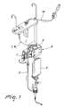
Figure 1 is a perspective view of a transfusion line comprising the device according to the invention; -
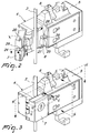
Figure 2 is a perspective view of the device according to the invention with the door open; -
Figure 3 is a perspective view of the device according to the invention with the door closed and with the blood conveyance duct in the closure position; -
Figures 4 and 5 are respectively sectional views taken along the lines IV-IV and V-V ofFigure 3 ; -
Figures 6 and 7 are the same sectional views, but with the blood conveyance duct in the open position; -
Figures 8, 9, 10 are respectively sectional views, taken along the line VIII-VIII and along the line IX-IX ofFigure 3 , and along the line X-X ofFigure 2 . - With reference to
figure 1 , which illustrates a blood transfusion line, the numeral 1 designates a blood collection tank, which can be of the type that comprises a mechanical supernatant separator, which reaches it through aduct 1a, connected by means of aduct 2 to a tank 3 for infusion to a patient; adevice 4 according to the invention is installed on theduct 2 and is now described with reference toFigures 2 to 10 . - The
device 4 comprises abody 5, which has a spring clip for engaging the overlying tank, and is provided with adoor 7 which is pivoted thereto and can move, along the arrow shown inFigure 1 , between an open position shown inFigures 1 and2 , which allows to associate the device with theduct 2, and an active closure position that is visible inFigure 3 ; amicroswitch 8 is pressed by thedoor 7 in such position, and operation is thus allowed. - The
body 5 accommodates, as shown inFigure 8 , the means adapted to detect the concentration of red blood cells in the blood conveyed by theduct 2, which comprise asource 9 of a luminous radiation that is arranged so that said radiation passes through theduct 2, exiting from it at areceiver 10. Since the optical density of the blood is directly proportional to the concentration of red blood cells, according to an important feature of the invention the degree of absorption that the radiation undergoes in passing through theduct 2 is measured, thereby determining said concentration. - For this purpose, the
source 9 and thereceiver 10 are connected to amanagement card 11, which is accommodated within the body above abattery 12 that powers the device; such card and such battery are visible inFigure 9 but not shown inFigures 4 and6 for graphical reasons. - When the described detection means, connected to the
management card 11, detect in the blood conveyed by the duct 2 a red blood cell concentration that is considered to be the lowest acceptable for infusion to the patient, a signal is sent from thecard 11 to means, which are now described in detail and which cause the closure of theduct 2. - Such means comprise, according to a further important feature of the invention, an
electric motor 13, on anoutput shaft 13a of which aneccentric support 14 is keyed, aroller 15 being associated with said support and being designed to move between two stroke limit positions. - The first stroke limit position is shown in
Figures 4 and 5 ; therein, theroller 15 compresses theduct 2 against anabutment 16 provided with anelastic element 17 until it is closed completely; the second stroke limit position is visible inFigures 6 and 7 ; therein, theroller 15 is not in contact with theduct 2, which is therefore in an open condition. - The
numerals output shaft 13a of theelectric motor 13 and, by operating in combination withmicroswitches - The
door 7 is provided with means for locking in the closed position, which comprise arod 20, which can slide axially, any rotation being prevented by atiming pin 21, in a seat formed in saiddoor 7, and is kept, by the action of aspring 22, in the lower stroke limit position in which it protrudes by means of abutton 23 from the lower face of thedoor 7. - The
rod 20 is provided, in an intermediate position, with aface 24, which is adapted to enter snugly anotch 25 for accessing aseat 26 designed to accommodate therod 20, which is formed in aplate 27 jointly connected to thebody 5. - The
notch 25 is flanked by an inclined plane 28, which is adapted to make contact with aninclined plane 29 that is present on therod 20 at the upper edge of theface 24, and thus during the closing motion of thedoor 7, while theface 24 passes through thenotch 25, therod 20 is lifted, with loading of thespring 22, which causes at the appropriate time the snap insertion of therod 20 in theseat 26, with consequent locking of thedoor 7. - To reopen such door it is sufficient to push the
rod 20 upwardly by operating thebutton 23. - The described invention is susceptible of numerous modifications and variations, all of which are within the scope of the appended claims; all the details may further be replaced with other technically equivalent elements.
- Where technical features mentioned in any claim are followed by reference signs, those reference signs have been included for the sole purpose of increasing the intelligibility of the claims and accordingly such reference signs do not have any limiting effect on the interpretation of each element identified by way of example by such reference signs.
Claims (5)
- A device for controlling the supply of red blood cells to a patient in a transfusion line, said transfusion line comprising a blood collection tank (1) connected by means of a duct (2) to a tank (3) for infusion to the patient or directly to the patient, and said device (4) being provided with detection means (9, 10) that are adapted to detect the concentration of red blood cells in the blood contained in the collection tank (1) by means of a detection performed on said tank (1) or on the duct (2) that connects said collection tank (1) to the tank (3) for infusion to the patient or directly to the patient, and that are adapted to actuate fastening means (14, 15, 16 and 17) that are adapted selectively to close and open said duct (2) in output from the collection tank (1) so as to block or respectively allow the passage of the liquid flow through it, said detection means (9, 10) adapted to detect the concentration of red blood cells in the blood contained in the collection tank (1) being adapted to measure the degree of absorption of a luminous radiation that passes through the blood, the device (4) further comprising a body (5) provided with a seat that allows to associate said device (4) with the duct (2) in output from the blood collection tank (1), characterized in that said detection means (9, 10) adapted to detect the concentration of red blood cells in the flow of blood conveyed by said duct (2) are inserted in said body (5), are connected to a management card (11) that is accommodated within said body (5) and comprise a source (9) of a luminous radiation that is arranged so that said radiation passes through said duct (2) and exits from it at a receiver (10), said body (5) further comprising inside it said fastening means that comprise an electric motor (13) controlled by the management card (11) and adapted to actuate an eccentric support (14) keyed on the output shaft of the motor (13) and which supports a roller (15) between a first stroke limit position, in which the roller (15) compresses the duct (2) against an abutment (16) until it causes its complete closure, and a second stroke limit position, in which the roller (15) is out of contact with said duct (2), which therefore is in the open condition.
- The device according to claim 1, characterized in that the body (5) comprises a door (7) that can move between an open position, which allows to associate said body (5) with the duct (2) in output from the blood collection tank (1), and a closed operating position.
- The device according to claim 1 or 2, characterized in that the roller (15) associated with the eccentric support (14) actuated by the electric motor (13) compresses the duct (2) for conveying the blood against an elastic abutment (17).
- The device according to one or more of the preceding claims, characterized by the presence of a stroke limiter for the motion of the electric motor for actuating the eccentric roller support (14) which comprises two cams (18, 19) that are associated adjustably with the output shaft (13a) of the motor (13) and operate in combination with microswitches (18a, 19a) associated with the management card (11) comprised within the body (5) of the device.
- The device according to one or more of the claims 2-4, characterized in that said door (7) is hinged to the body of the device and is provided with means for locking in a closure position, which comprise a rod (20) that can slide axially within a seat that is formed in the door (7) and is maintained by the action of elastic means (22) in the lower stroke limit position, in which it protrudes by means of a button (23) from the lower face of said door (7), said rod (20) being provided, in an intermediate position, with a recess (24) that is adapted to be inserted snugly in an access notch (25) for accessing a seat (26) designed to accommodate said rod (20) formed in a plate (27) that is jointly connected to said body (5), said notch (25) being flanked by an inclined plane (28) that is adapted to come into contact with a corresponding inclined plane (29) that is provided on the rod (20) at the upper edge of the recess (24), so as to lift the rod (20) during the closing motion of the door (7) at the notch (25) up to snap insertion in its seat (26) produced by the action of the elastic means (22), with consequent locking of the door (7).
Applications Claiming Priority (1)
| Application Number | Priority Date | Filing Date | Title |
|---|---|---|---|
| IT000579A ITMI20090579A1 (en) | 2009-04-09 | 2009-04-09 | CONTROL DEVICE FOR THE ADMISSION OF RED GLOBULES TO A PATIENT IN LINE OF TRANSFUSION. |
Publications (2)
| Publication Number | Publication Date |
|---|---|
| EP2272551A1 EP2272551A1 (en) | 2011-01-12 |
| EP2272551B1 true EP2272551B1 (en) | 2012-06-06 |
Family
ID=41228824
Family Applications (1)
| Application Number | Title | Priority Date | Filing Date |
|---|---|---|---|
| EP10157638A Active EP2272551B1 (en) | 2009-04-09 | 2010-03-24 | Device for controlling the supply of red blood cells to a patient in a transfusion line |
Country Status (2)
| Country | Link |
|---|---|
| EP (1) | EP2272551B1 (en) |
| IT (1) | ITMI20090579A1 (en) |
Families Citing this family (1)
| Publication number | Priority date | Publication date | Assignee | Title |
|---|---|---|---|---|
| CN104721905B (en) * | 2015-03-26 | 2018-06-19 | 高海燕 | A kind of surgery Mobile portable formula infusion support |
Family Cites Families (8)
| Publication number | Priority date | Publication date | Assignee | Title |
|---|---|---|---|---|
| US3215394A (en) * | 1962-04-23 | 1965-11-02 | Sherman Lab | Regulable tube clamping device for intravenous injection set |
| US4807676A (en) * | 1985-02-26 | 1989-02-28 | Baxter International Inc. | Fluid transfer workstation |
| US4697785A (en) * | 1986-04-14 | 1987-10-06 | Tuseth Robert D | Clamp for regulating flow of parenteral solutions |
| FR2625320B1 (en) * | 1987-12-28 | 1990-05-18 | Rgl Transfusion Sanguine Centr | AUTOMATIC BLOOD COMPONENT SEPARATION APPARATUS |
| JP2547636B2 (en) * | 1989-07-14 | 1996-10-23 | テルモ株式会社 | Liquid separation device |
| US5282982A (en) * | 1991-07-12 | 1994-02-01 | Wells John R | Blood washing method |
| JP3817091B2 (en) * | 1999-07-02 | 2006-08-30 | テルモ株式会社 | Cell number measuring device |
| NL2000116C2 (en) * | 2006-06-29 | 2008-01-02 | Klip Consultancy B V | Device comprising a container system for a body fluid. |
-
2009
- 2009-04-09 IT IT000579A patent/ITMI20090579A1/en unknown
-
2010
- 2010-03-24 EP EP10157638A patent/EP2272551B1/en active Active
Also Published As
| Publication number | Publication date |
|---|---|
| ITMI20090579A1 (en) | 2010-10-10 |
| EP2272551A1 (en) | 2011-01-12 |
Similar Documents
| Publication | Publication Date | Title |
|---|---|---|
| EP2081475B1 (en) | Jug for filtering liquids | |
| CN101188029A (en) | Banknote deposit and withdrawal device and banknote deposit and withdrawal device control method | |
| EP2272551A1 (en) | Device for controlling the supply of red blood cells to a patient in a transfusion line | |
| EP2723415A1 (en) | Blood bag valve breaker | |
| Dousdampanis et al. | Prevalence of anemia in patients with type II diabetes and mild to moderate chronic kidney disease and the impact of anti-RAS medications | |
| US20210100944A1 (en) | Fluid temperature control device for an extracorporeal blood treatment apparatus and extracorporeal blood treatment apparatus | |
| GB2374521A (en) | Secure powered drawer with timed opening and opening speed controls | |
| CN102376121A (en) | Coin processing device | |
| EP2868333B1 (en) | Method and apparatus to verify correct replacement fluid in a therapeutic exchange procedure | |
| US10406464B2 (en) | Drain control device for a filter system as well as filter system with a drain control device | |
| US20170312669A1 (en) | Drain Control Device for a Filter System as well as Filter System with a Drain Control Device | |
| Capalbo et al. | Early deferasirox treatment in a patient with myelodysplastic syndrome results in a long-term reduction in transfusion requirements. | |
| US10328189B2 (en) | Methods and systems for reducing the risk of bacterial contamination in collected platelets | |
| CN104077853A (en) | Paper sheet handling device and automatic transaction device | |
| CN208510340U (en) | A kind of financial management intelligent multifunctional safety cabinet | |
| CN214919122U (en) | Waste treatment system applied to automatic molecular diagnostic instrument | |
| EP2119461A2 (en) | Postoperative autotransfusion device with improved efficiency | |
| Kulier | Anemia and morbidity and mortality in coronary bypass surgery | |
| Charuruks et al. | Ratio of baseline erythropoietin (EPO) level and corrected reticulocyte count as an indicator for a favourable response to recombinant human erythropoietin (rhEPO) therapy in anaemic cancer patients | |
| CN105350856A (en) | Automatic vault door | |
| CN208954187U (en) | Paper money door gear and finance device | |
| JP3755450B2 (en) | Centrifugal separator with balance weight creation function | |
| TR202020747A2 (en) | A TURKISH COFFEE MACHINE | |
| EP2944339A1 (en) | Systems and methods for determining replacement fluid and plasma flow rates for red blood cell exchange procedures | |
| CN209385011U (en) | A kind of Solid Door of finger |
Legal Events
| Date | Code | Title | Description |
|---|---|---|---|
| PUAI | Public reference made under article 153(3) epc to a published international application that has entered the european phase |
Free format text: ORIGINAL CODE: 0009012 |
|
| AK | Designated contracting states |
Kind code of ref document: A1 Designated state(s): AT BE BG CH CY CZ DE DK EE ES FI FR GB GR HR HU IE IS IT LI LT LU LV MC MK MT NL NO PL PT RO SE SI SK SM TR |
|
| AX | Request for extension of the european patent |
Extension state: AL BA ME RS |
|
| 17P | Request for examination filed |
Effective date: 20110708 |
|
| RIC1 | Information provided on ipc code assigned before grant |
Ipc: A61M 39/28 20060101ALI20110908BHEP Ipc: A61M 1/02 20060101AFI20110908BHEP |
|
| GRAP | Despatch of communication of intention to grant a patent |
Free format text: ORIGINAL CODE: EPIDOSNIGR1 |
|
| GRAS | Grant fee paid |
Free format text: ORIGINAL CODE: EPIDOSNIGR3 |
|
| GRAA | (expected) grant |
Free format text: ORIGINAL CODE: 0009210 |
|
| AK | Designated contracting states |
Kind code of ref document: B1 Designated state(s): AT BE BG CH CY CZ DE DK EE ES FI FR GB GR HR HU IE IS IT LI LT LU LV MC MK MT NL NO PL PT RO SE SI SK SM TR |
|
| REG | Reference to a national code |
Ref country code: GB Ref legal event code: FG4D |
|
| REG | Reference to a national code |
Ref country code: AT Ref legal event code: REF Ref document number: 560696 Country of ref document: AT Kind code of ref document: T Effective date: 20120615 Ref country code: CH Ref legal event code: EP |
|
| REG | Reference to a national code |
Ref country code: IE Ref legal event code: FG4D |
|
| REG | Reference to a national code |
Ref country code: DE Ref legal event code: R096 Ref document number: 602010001800 Country of ref document: DE Effective date: 20120802 |
|
| REG | Reference to a national code |
Ref country code: NL Ref legal event code: VDEP Effective date: 20120606 |
|
| PG25 | Lapsed in a contracting state [announced via postgrant information from national office to epo] |
Ref country code: LT Free format text: LAPSE BECAUSE OF FAILURE TO SUBMIT A TRANSLATION OF THE DESCRIPTION OR TO PAY THE FEE WITHIN THE PRESCRIBED TIME-LIMIT Effective date: 20120606 Ref country code: CY Free format text: LAPSE BECAUSE OF FAILURE TO SUBMIT A TRANSLATION OF THE DESCRIPTION OR TO PAY THE FEE WITHIN THE PRESCRIBED TIME-LIMIT Effective date: 20120606 Ref country code: FI Free format text: LAPSE BECAUSE OF FAILURE TO SUBMIT A TRANSLATION OF THE DESCRIPTION OR TO PAY THE FEE WITHIN THE PRESCRIBED TIME-LIMIT Effective date: 20120606 Ref country code: NO Free format text: LAPSE BECAUSE OF FAILURE TO SUBMIT A TRANSLATION OF THE DESCRIPTION OR TO PAY THE FEE WITHIN THE PRESCRIBED TIME-LIMIT Effective date: 20120906 Ref country code: SE Free format text: LAPSE BECAUSE OF FAILURE TO SUBMIT A TRANSLATION OF THE DESCRIPTION OR TO PAY THE FEE WITHIN THE PRESCRIBED TIME-LIMIT Effective date: 20120606 |
|
| REG | Reference to a national code |
Ref country code: AT Ref legal event code: MK05 Ref document number: 560696 Country of ref document: AT Kind code of ref document: T Effective date: 20120606 |
|
| REG | Reference to a national code |
Ref country code: LT Ref legal event code: MG4D Effective date: 20120606 |
|
| PG25 | Lapsed in a contracting state [announced via postgrant information from national office to epo] |
Ref country code: HR Free format text: LAPSE BECAUSE OF FAILURE TO SUBMIT A TRANSLATION OF THE DESCRIPTION OR TO PAY THE FEE WITHIN THE PRESCRIBED TIME-LIMIT Effective date: 20120606 Ref country code: LV Free format text: LAPSE BECAUSE OF FAILURE TO SUBMIT A TRANSLATION OF THE DESCRIPTION OR TO PAY THE FEE WITHIN THE PRESCRIBED TIME-LIMIT Effective date: 20120606 Ref country code: GR Free format text: LAPSE BECAUSE OF FAILURE TO SUBMIT A TRANSLATION OF THE DESCRIPTION OR TO PAY THE FEE WITHIN THE PRESCRIBED TIME-LIMIT Effective date: 20120907 Ref country code: SI Free format text: LAPSE BECAUSE OF FAILURE TO SUBMIT A TRANSLATION OF THE DESCRIPTION OR TO PAY THE FEE WITHIN THE PRESCRIBED TIME-LIMIT Effective date: 20120606 |
|
| PG25 | Lapsed in a contracting state [announced via postgrant information from national office to epo] |
Ref country code: RO Free format text: LAPSE BECAUSE OF FAILURE TO SUBMIT A TRANSLATION OF THE DESCRIPTION OR TO PAY THE FEE WITHIN THE PRESCRIBED TIME-LIMIT Effective date: 20120606 Ref country code: AT Free format text: LAPSE BECAUSE OF FAILURE TO SUBMIT A TRANSLATION OF THE DESCRIPTION OR TO PAY THE FEE WITHIN THE PRESCRIBED TIME-LIMIT Effective date: 20120606 Ref country code: BE Free format text: LAPSE BECAUSE OF FAILURE TO SUBMIT A TRANSLATION OF THE DESCRIPTION OR TO PAY THE FEE WITHIN THE PRESCRIBED TIME-LIMIT Effective date: 20120606 Ref country code: IS Free format text: LAPSE BECAUSE OF FAILURE TO SUBMIT A TRANSLATION OF THE DESCRIPTION OR TO PAY THE FEE WITHIN THE PRESCRIBED TIME-LIMIT Effective date: 20121006 Ref country code: EE Free format text: LAPSE BECAUSE OF FAILURE TO SUBMIT A TRANSLATION OF THE DESCRIPTION OR TO PAY THE FEE WITHIN THE PRESCRIBED TIME-LIMIT Effective date: 20120606 Ref country code: CZ Free format text: LAPSE BECAUSE OF FAILURE TO SUBMIT A TRANSLATION OF THE DESCRIPTION OR TO PAY THE FEE WITHIN THE PRESCRIBED TIME-LIMIT Effective date: 20120606 Ref country code: SK Free format text: LAPSE BECAUSE OF FAILURE TO SUBMIT A TRANSLATION OF THE DESCRIPTION OR TO PAY THE FEE WITHIN THE PRESCRIBED TIME-LIMIT Effective date: 20120606 Ref country code: NL Free format text: LAPSE BECAUSE OF FAILURE TO SUBMIT A TRANSLATION OF THE DESCRIPTION OR TO PAY THE FEE WITHIN THE PRESCRIBED TIME-LIMIT Effective date: 20120606 |
|
| PG25 | Lapsed in a contracting state [announced via postgrant information from national office to epo] |
Ref country code: PL Free format text: LAPSE BECAUSE OF FAILURE TO SUBMIT A TRANSLATION OF THE DESCRIPTION OR TO PAY THE FEE WITHIN THE PRESCRIBED TIME-LIMIT Effective date: 20120606 Ref country code: PT Free format text: LAPSE BECAUSE OF FAILURE TO SUBMIT A TRANSLATION OF THE DESCRIPTION OR TO PAY THE FEE WITHIN THE PRESCRIBED TIME-LIMIT Effective date: 20121008 |
|
| PLBE | No opposition filed within time limit |
Free format text: ORIGINAL CODE: 0009261 |
|
| STAA | Information on the status of an ep patent application or granted ep patent |
Free format text: STATUS: NO OPPOSITION FILED WITHIN TIME LIMIT |
|
| PG25 | Lapsed in a contracting state [announced via postgrant information from national office to epo] |
Ref country code: ES Free format text: LAPSE BECAUSE OF FAILURE TO SUBMIT A TRANSLATION OF THE DESCRIPTION OR TO PAY THE FEE WITHIN THE PRESCRIBED TIME-LIMIT Effective date: 20120917 Ref country code: DK Free format text: LAPSE BECAUSE OF FAILURE TO SUBMIT A TRANSLATION OF THE DESCRIPTION OR TO PAY THE FEE WITHIN THE PRESCRIBED TIME-LIMIT Effective date: 20120606 |
|
| 26N | No opposition filed |
Effective date: 20130307 |
|
| REG | Reference to a national code |
Ref country code: DE Ref legal event code: R097 Ref document number: 602010001800 Country of ref document: DE Effective date: 20130307 |
|
| PG25 | Lapsed in a contracting state [announced via postgrant information from national office to epo] |
Ref country code: BG Free format text: LAPSE BECAUSE OF FAILURE TO SUBMIT A TRANSLATION OF THE DESCRIPTION OR TO PAY THE FEE WITHIN THE PRESCRIBED TIME-LIMIT Effective date: 20120906 |
|
| PG25 | Lapsed in a contracting state [announced via postgrant information from national office to epo] |
Ref country code: MC Free format text: LAPSE BECAUSE OF NON-PAYMENT OF DUE FEES Effective date: 20130331 |
|
| REG | Reference to a national code |
Ref country code: IE Ref legal event code: MM4A |
|
| PG25 | Lapsed in a contracting state [announced via postgrant information from national office to epo] |
Ref country code: IE Free format text: LAPSE BECAUSE OF NON-PAYMENT OF DUE FEES Effective date: 20130324 |
|
| PG25 | Lapsed in a contracting state [announced via postgrant information from national office to epo] |
Ref country code: MT Free format text: LAPSE BECAUSE OF FAILURE TO SUBMIT A TRANSLATION OF THE DESCRIPTION OR TO PAY THE FEE WITHIN THE PRESCRIBED TIME-LIMIT Effective date: 20120606 |
|
| REG | Reference to a national code |
Ref country code: CH Ref legal event code: PL |
|
| PG25 | Lapsed in a contracting state [announced via postgrant information from national office to epo] |
Ref country code: CH Free format text: LAPSE BECAUSE OF NON-PAYMENT OF DUE FEES Effective date: 20140331 Ref country code: LI Free format text: LAPSE BECAUSE OF NON-PAYMENT OF DUE FEES Effective date: 20140331 |
|
| PG25 | Lapsed in a contracting state [announced via postgrant information from national office to epo] |
Ref country code: SM Free format text: LAPSE BECAUSE OF FAILURE TO SUBMIT A TRANSLATION OF THE DESCRIPTION OR TO PAY THE FEE WITHIN THE PRESCRIBED TIME-LIMIT Effective date: 20120606 |
|
| PG25 | Lapsed in a contracting state [announced via postgrant information from national office to epo] |
Ref country code: TR Free format text: LAPSE BECAUSE OF FAILURE TO SUBMIT A TRANSLATION OF THE DESCRIPTION OR TO PAY THE FEE WITHIN THE PRESCRIBED TIME-LIMIT Effective date: 20120606 |
|
| PG25 | Lapsed in a contracting state [announced via postgrant information from national office to epo] |
Ref country code: HU Free format text: LAPSE BECAUSE OF FAILURE TO SUBMIT A TRANSLATION OF THE DESCRIPTION OR TO PAY THE FEE WITHIN THE PRESCRIBED TIME-LIMIT; INVALID AB INITIO Effective date: 20100324 Ref country code: MK Free format text: LAPSE BECAUSE OF FAILURE TO SUBMIT A TRANSLATION OF THE DESCRIPTION OR TO PAY THE FEE WITHIN THE PRESCRIBED TIME-LIMIT Effective date: 20120606 Ref country code: LU Free format text: LAPSE BECAUSE OF NON-PAYMENT OF DUE FEES Effective date: 20130324 |
|
| REG | Reference to a national code |
Ref country code: FR Ref legal event code: PLFP Year of fee payment: 7 |
|
| PGFP | Annual fee paid to national office [announced via postgrant information from national office to epo] |
Ref country code: GB Payment date: 20160329 Year of fee payment: 7 |
|
| REG | Reference to a national code |
Ref country code: FR Ref legal event code: PLFP Year of fee payment: 8 |
|
| GBPC | Gb: european patent ceased through non-payment of renewal fee |
Effective date: 20170324 |
|
| PG25 | Lapsed in a contracting state [announced via postgrant information from national office to epo] |
Ref country code: GB Free format text: LAPSE BECAUSE OF NON-PAYMENT OF DUE FEES Effective date: 20170324 |
|
| REG | Reference to a national code |
Ref country code: FR Ref legal event code: PLFP Year of fee payment: 9 |
|
| PGFP | Annual fee paid to national office [announced via postgrant information from national office to epo] |
Ref country code: DE Payment date: 20220329 Year of fee payment: 13 |
|
| PGFP | Annual fee paid to national office [announced via postgrant information from national office to epo] |
Ref country code: FR Payment date: 20220325 Year of fee payment: 13 |
|
| P01 | Opt-out of the competence of the unified patent court (upc) registered |
Effective date: 20230527 |
|
| REG | Reference to a national code |
Ref country code: DE Ref legal event code: R119 Ref document number: 602010001800 Country of ref document: DE |
|
| PG25 | Lapsed in a contracting state [announced via postgrant information from national office to epo] |
Ref country code: FR Free format text: LAPSE BECAUSE OF NON-PAYMENT OF DUE FEES Effective date: 20230331 Ref country code: DE Free format text: LAPSE BECAUSE OF NON-PAYMENT OF DUE FEES Effective date: 20231003 |
|
| PGFP | Annual fee paid to national office [announced via postgrant information from national office to epo] |
Ref country code: IT Payment date: 20260320 Year of fee payment: 17 |