EP2271274B1 - Dispositif pour fixer des fragments d'os sur des fractures osseuses - Google Patents
Dispositif pour fixer des fragments d'os sur des fractures osseuses Download PDFInfo
- Publication number
- EP2271274B1 EP2271274B1 EP09724294.5A EP09724294A EP2271274B1 EP 2271274 B1 EP2271274 B1 EP 2271274B1 EP 09724294 A EP09724294 A EP 09724294A EP 2271274 B1 EP2271274 B1 EP 2271274B1
- Authority
- EP
- European Patent Office
- Prior art keywords
- bone
- securing plate
- fixation means
- securing
- fixation
- Prior art date
- Legal status (The legal status is an assumption and is not a legal conclusion. Google has not performed a legal analysis and makes no representation as to the accuracy of the status listed.)
- Active
Links
- 210000000988 bone and bone Anatomy 0.000 title claims description 155
- 239000012634 fragment Substances 0.000 title claims description 79
- 208000010392 Bone Fractures Diseases 0.000 title claims description 15
- 238000005553 drilling Methods 0.000 claims description 8
- 230000006835 compression Effects 0.000 claims description 4
- 238000007906 compression Methods 0.000 claims description 4
- 230000002093 peripheral effect Effects 0.000 claims description 3
- 238000001356 surgical procedure Methods 0.000 claims description 2
- 210000002436 femur neck Anatomy 0.000 description 4
- 210000000689 upper leg Anatomy 0.000 description 4
- 238000000034 method Methods 0.000 description 3
- 206010002091 Anaesthesia Diseases 0.000 description 1
- 238000001949 anaesthesia Methods 0.000 description 1
- 230000037005 anaesthesia Effects 0.000 description 1
- 239000000470 constituent Substances 0.000 description 1
- 230000006735 deficit Effects 0.000 description 1
- 230000000694 effects Effects 0.000 description 1
- 230000035876 healing Effects 0.000 description 1
- 210000002758 humerus Anatomy 0.000 description 1
- 238000003780 insertion Methods 0.000 description 1
- 230000037431 insertion Effects 0.000 description 1
- 210000002414 leg Anatomy 0.000 description 1
- 239000000463 material Substances 0.000 description 1
- 238000012544 monitoring process Methods 0.000 description 1
- 239000007787 solid Substances 0.000 description 1
Images


Classifications
-
- A—HUMAN NECESSITIES
- A61—MEDICAL OR VETERINARY SCIENCE; HYGIENE
- A61B—DIAGNOSIS; SURGERY; IDENTIFICATION
- A61B17/00—Surgical instruments, devices or methods, e.g. tourniquets
- A61B17/56—Surgical instruments or methods for treatment of bones or joints; Devices specially adapted therefor
- A61B17/58—Surgical instruments or methods for treatment of bones or joints; Devices specially adapted therefor for osteosynthesis, e.g. bone plates, screws, setting implements or the like
- A61B17/68—Internal fixation devices, including fasteners and spinal fixators, even if a part thereof projects from the skin
- A61B17/74—Devices for the head or neck or trochanter of the femur
- A61B17/742—Devices for the head or neck or trochanter of the femur having one or more longitudinal elements oriented along or parallel to the axis of the neck
- A61B17/746—Devices for the head or neck or trochanter of the femur having one or more longitudinal elements oriented along or parallel to the axis of the neck the longitudinal elements coupled to a plate opposite the femoral head
-
- A—HUMAN NECESSITIES
- A61—MEDICAL OR VETERINARY SCIENCE; HYGIENE
- A61B—DIAGNOSIS; SURGERY; IDENTIFICATION
- A61B17/00—Surgical instruments, devices or methods, e.g. tourniquets
- A61B17/56—Surgical instruments or methods for treatment of bones or joints; Devices specially adapted therefor
- A61B17/58—Surgical instruments or methods for treatment of bones or joints; Devices specially adapted therefor for osteosynthesis, e.g. bone plates, screws, setting implements or the like
- A61B17/68—Internal fixation devices, including fasteners and spinal fixators, even if a part thereof projects from the skin
- A61B17/74—Devices for the head or neck or trochanter of the femur
-
- A—HUMAN NECESSITIES
- A61—MEDICAL OR VETERINARY SCIENCE; HYGIENE
- A61B—DIAGNOSIS; SURGERY; IDENTIFICATION
- A61B17/00—Surgical instruments, devices or methods, e.g. tourniquets
- A61B17/56—Surgical instruments or methods for treatment of bones or joints; Devices specially adapted therefor
- A61B17/58—Surgical instruments or methods for treatment of bones or joints; Devices specially adapted therefor for osteosynthesis, e.g. bone plates, screws, setting implements or the like
- A61B17/68—Internal fixation devices, including fasteners and spinal fixators, even if a part thereof projects from the skin
- A61B17/80—Cortical plates, i.e. bone plates; Instruments for holding or positioning cortical plates, or for compressing bones attached to cortical plates
- A61B17/8033—Cortical plates, i.e. bone plates; Instruments for holding or positioning cortical plates, or for compressing bones attached to cortical plates having indirect contact with screw heads, or having contact with screw heads maintained with the aid of additional components, e.g. nuts, wedges or head covers
- A61B17/8042—Cortical plates, i.e. bone plates; Instruments for holding or positioning cortical plates, or for compressing bones attached to cortical plates having indirect contact with screw heads, or having contact with screw heads maintained with the aid of additional components, e.g. nuts, wedges or head covers the additional component being a cover over the screw head
-
- A—HUMAN NECESSITIES
- A61—MEDICAL OR VETERINARY SCIENCE; HYGIENE
- A61B—DIAGNOSIS; SURGERY; IDENTIFICATION
- A61B17/00—Surgical instruments, devices or methods, e.g. tourniquets
- A61B17/56—Surgical instruments or methods for treatment of bones or joints; Devices specially adapted therefor
- A61B17/58—Surgical instruments or methods for treatment of bones or joints; Devices specially adapted therefor for osteosynthesis, e.g. bone plates, screws, setting implements or the like
- A61B17/68—Internal fixation devices, including fasteners and spinal fixators, even if a part thereof projects from the skin
- A61B17/84—Fasteners therefor or fasteners being internal fixation devices
- A61B17/86—Pins or screws or threaded wires; nuts therefor
- A61B17/8625—Shanks, i.e. parts contacting bone tissue
- A61B17/863—Shanks, i.e. parts contacting bone tissue with thread interrupted or changing its form along shank, other than constant taper
-
- A—HUMAN NECESSITIES
- A61—MEDICAL OR VETERINARY SCIENCE; HYGIENE
- A61B—DIAGNOSIS; SURGERY; IDENTIFICATION
- A61B17/00—Surgical instruments, devices or methods, e.g. tourniquets
- A61B17/56—Surgical instruments or methods for treatment of bones or joints; Devices specially adapted therefor
- A61B17/58—Surgical instruments or methods for treatment of bones or joints; Devices specially adapted therefor for osteosynthesis, e.g. bone plates, screws, setting implements or the like
- A61B17/68—Internal fixation devices, including fasteners and spinal fixators, even if a part thereof projects from the skin
- A61B17/84—Fasteners therefor or fasteners being internal fixation devices
- A61B17/86—Pins or screws or threaded wires; nuts therefor
-
- A—HUMAN NECESSITIES
- A61—MEDICAL OR VETERINARY SCIENCE; HYGIENE
- A61B—DIAGNOSIS; SURGERY; IDENTIFICATION
- A61B90/00—Instruments, implements or accessories specially adapted for surgery or diagnosis and not covered by any of the groups A61B1/00 - A61B50/00, e.g. for luxation treatment or for protecting wound edges
- A61B90/06—Measuring instruments not otherwise provided for
- A61B2090/061—Measuring instruments not otherwise provided for for measuring dimensions, e.g. length
Definitions
- the present invention relates to a device for fixation of bone fragments at bone fractures.
- the bone fragments at the fracture need fixing. This is currently done by using suitable fixation means, e.g. bone nails or bone screws.
- fixation means alone are often insufficient to counteract these rotational forces and the bone fragments have to be used to help to lock the fracture. If this is not done and the bone fragments are caused to rotate relative to one another by said forces, the result will be shifting of the angular positions of the fixation means to such an extent that they risk substantially crossing one another, thereby keeping the fracture parted and preventing healing.
- the object of the present invention is accordingly to prevent or counteract this and therefore configure the device in such a way that the fixation means are not allowed to rotate and cross one another.
- a device comprises at least two fixation means, a securing plate and at least one securing means for the fixation means, that each fixation means has a first fixing portion for fixing the fixation means in an inner bone fragment, a second fixing portion to serve in conjunction with the securing means for locking the fixation means in a hole which runs through the securing plate disposed on the outside of an outer bone fragment and allowing movement of the outer bone fragment relative to it, so that the fixation means are prevented from changing their angular position relative to the securing plate and relative to one another, and a middle portion which is situated between the fixing portions and runs through the outer bone fragment, along which middle portion the outer bone fragment can slide inwards towards the inner bone fragment in which the fixation means are fixed, and that the securing means has an external thread for screwing it firmly into a hole in the securing plate.
- fixation means being thus fixed to the inner bone fragment and to the securing plate while the outer bone fragment can move towards the inner bone fragment and, in so doing, be guided by the fixation means is that the bone fragments are kept fixed but compression of the bone fragments is nevertheless allowed, the device and the bone fragments thus being able to absorb the aforesaid rotational forces and control them so that no redislocation occurs.
- the fixing of the fixation means in the inner bone fragment and the locking of the fixation means to the securing plate also reduce the risk of screws loosening in cases where the fixation means take the form of bone screws.
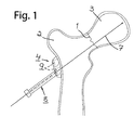
- FIG. 1 depicts upper portions of a femur with a femur neck fracture 1, and an outer bone fragment 2 and an inner bone fragment 3 on their respective sides of the fracture.
- the respective bone screws 5, 6 are preferably integral.
- the securing plate 4 is so arranged that it allows movement of the outer bone fragment 2 relative to it, i.e. it is not connected to the outer bone fragment nor disposed in some other way whereby it would move with the latter upon compression of the bone fragments 2, 3.
- a guide wire 7 with a diameter of preferably about 2.4 mm has been drilled through the outer bone fragment 2 and into the inner bone fragment 3 under radioscopy and with guidance by a guide sleeve 8 with an inside diameter of preferably about 2.5 mm.
- the guide wire 7 is intended to guide a drill for drilling a hole for the bone screw 5 in the bone fragments 2, 3.
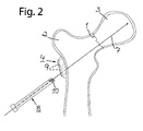
- the guide sleeve 8 for the guide wire 7 is applied in the securing plate 4, preferably by being screwed firmly into an, in the embodiment depicted, at least partly threaded hole 9 running through the plate, and has for the purpose an externally threaded forward end portion 10 (see Fig. 2 depicting the guide sleeve 8 when it has been unscrewed from the plate 4).
- This externally threaded forward end portion 10 does of course have an outside diameter corresponding to the diameter of the threaded portion 9a of the at least partly threaded hole 9 in the securing plate 4, i.e. preferably about 9-10 mm.
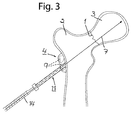
- a second guide sleeve 11 with an inside diameter of preferably about 6.5 mm and an externally threaded forward portion with the same outside diameter as the first guide sleeve, is applied in, i.e. screwed into, the threaded portion 9a of the at least partly threaded hole 9 in the securing plate 4 ( Fig. 3 ).
- This guide sleeve 11 is intended to guide a drill 13, which has running through it a duct 12 for the wire guide 7 (see Figs. 5-10 ), in order to drill the hole for the bone screw 5 in the bone fragments 2, 3.
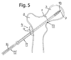
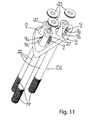
- the hole for the bone screw 5 can now be drilled. Accordingly, as illustrated in Fig. 5 , the drill 13 provided with the duct 12 is introduced through the guide sleeve 11 towards the bone fragment 2 and the drilling of the hole for the bone screw 5 is commenced, using a suitable drive device 15.
- the drill 13 has an outside diameter of preferably about 6.5 mm and fits exactly in the guide sleeve 11.
- the drill 13 is guided by the guide sleeve 11 to correct position against the bone fragment 2 and thereafter by the guide wire 7 through the bone fragment 2 and past the fracture 1 into the bone fragment 3.
- Monitoring that the hole for the bone screw 5 is of correct length is carried out with advantage at the rear of the guide sleeve 11, where the drill 13 or the drive device 15 bears suitable markings 16. This entails the drill 13 being halted about 2 cm from the tip of the guide wire 7, i.e. about 2 cm before reaching the point to which the bone screw 5 is intended to be screwed in.
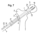
- the guide sleeve 11 in the version depicted is intended to guide a drill 17 without a duct for the guide wire but with a cone-shaped tip (see Fig. 7 ).
- This solid drill 17 is drilled in to desired position for the bone screw 6 by means of the drive device 15. Correct length is read with advantage at the rear of the guide sleeve 11, where the drill 17 or the drive device 15 bears suitable markings 16 ( Fig. 7 ).
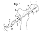
- the drill 17 and the guide sleeve 11 for it are removed ( Fig. 8 ), leaving for the bone screw 6 a hole 18 in the bone fragments 2, 3 which is shorter than the distance to which the bone screw is intended to be screwed in.
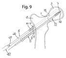
- the bone screw 6 can now, by means of a first fixing portion in the form of a threaded forward end portion 19, be inserted in through the at least partly threaded clear hole 9 in the securing plate 4 (see Fig. 9 ) and be screwed into the hole 18 in the bone fragments 2, 3 in order to fix these bone fragments.
- This is effected without the threaded forward end portion 19 of the bone screw 6 cooperating with the thread in the threaded portion 9a of the at least partly threaded hole 9 in the plate 4.
- the thread on the threaded forward end portion 19 of the bone screw 6 may be about 8 mm, while the thread in the at least partly threaded hole 9 in the securing plate 4 may, as previously indicated, be about 9-10 mm.
- the bone screw 6 is screwed in by using a suitable tool, in the version depicted a suitable type of screwdriver 20. Alternatively it is of course possible to conceive of using for this purpose the same drive device 15 as for the drills 13, 17.
- the bone screw 6 is screwed in until a second fixing portion in the form of a unthreaded rear end portion 21 thereof which narrows conically in the screwing-in direction of the bone screw cooperates with, preferably abuts against, a corresponding conically narrowing unthreaded portion 9b of the at least partly threaded hole 9 in the securing plate 4, while at the same time the threaded forward portion 19 of the bone screw is screwed through the outer bone fragment 2 and into the inner bone fragment 3 for engagement therein and locking of this latter bone fragment to the bone screw.
- the conically narrowing end portion 21 of the bone screw 6 preferably narrows from about 9-10 mm to about 6.5 mm in the screwing-in direction of the bone screw.
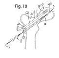
- the middle portion 22 of the bone screw 6, which is preferably unthreaded, has with advantage an outside diameter corresponding to that of the drill 17, i.e. about 6.5 mm. In Fig. 10 the bone screw 6 is fully screwed in.
- a securing means 23 ( Figs.
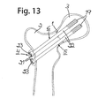
- Fig. 13 the drill 13, the guide sleeve 11 for the drill, and the guide wire 7 have been removed.
- the bone screw 5, preferably similar in form to the bone screw 6, is introduced into the at least partly threaded hole 9 in the plate 4 vacated by the removal of said items and into the hole 24 created by the drill 13 ( Fig. 10 ) in the bone fragments 2, 3 for fixation of the bone fragments after locking also of this bone screw by a securing means 23.
- each securing means comprises a lock washer 23 with a peripheral thread and a central recess for a suitable screwing tool, e.g. the screwdriver 20.
- the lock washer 23 has preferably a thickness of about 3 mm.
- the respective securing means 23 may alternatively take the form of a locking screw (not depicted).
- the bone screws 5, 6, as also the lock washer 23 and the screwing tool, e.g. the screwdriver 20, may be cannulated, i.e. have a longitudinal duct, and may in this way also be guided by a guide wire 7 on which these items can be threaded so that the guide wire runs through the duct.
- Securing means 23 of some other type, e.g. locking screws, may of course also be cannulated.
- the bone screws 5, 6 are also configured, as a result of their smooth middle portion 22, to allow the bone fragments 2, 3 to be compressed so that the outer bone fragment 2 slides inwards away from the securing plate 4 towards the inner bone fragment 3 into which the bone screws are firmly screwed.
- the securing plate 4 will, through being locked to the bone screws 5, 6 by the securing means 23, move away from its abutment against the outer bone fragment 2 (as represented schematically in Fig. 14 by the intermediate space 25 between the securing plate and the outer bone fragment), but without affecting the strength of the connection and without impairment of function.
- the device according to the present invention may be provided with only one securing means 23, which in that case will be common to all the fixation means 5, 6.
- the holes 9 in the securing plate 4 will then not need to be threaded, at least not for locking of the fixation means, but may with advantage be replaced by a separate threaded hole (not depicted) for the securing means 23, situated centrally in the securing plate between the holes 9 for the fixation means. In that case all of the fixation means will be locked simultaneously by the securing means being screwed firmly into the threaded hole intended for it.
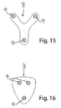
- Figs. 15 and 16 depict alternative versions of the securing plate 4.
- the securing plate 4 has in these versions three at least partly threaded holes 9 for bone screws, viz. two upper holes and one lower hole.
- the securing plate 4 may be configured in various sizes.
- the securing plate 4 may be so configured that the distance between the upper holes 9 amounts to about 4.5, 6 or 7.5 mm, while the distance between the lower hole 9 and the respective upper holes 9 amounts to 6, 8 or 10 mm.
- the at least partly threaded holes 9 for the bone screws run substantially parallel with one another so that the bone screws 5, 6 will likewise run substantially parallel with one another.
- Parallel running of the fixation means facilitates in particular the sliding movement of the outer bone fragment 2 along the fixation means (along the middle portion 22 thereof) for compression of the bone fragments.
- the securing plate 4 according to the present invention may be used not only for femur neck ( collum ) fractures but also for, for example, upper arm ( humerus ) fractures.
- the device according to the invention also allows the application of guide sleeves for guidance of drills for drilling holes for the bone screws in the bone fragments, and/or guide sleeves for guidance of guide wires for said drills, in the same holes in the securing plate as are intended for the fixation means. This means that surgical staff need no longer keep count of an unnecessarily large number of different items for performing an operation, operating time becomes shorter and risks and complications for patients are reduced.
- the securing plate 4 may be used for guide sleeves 8 for guide wires and thereafter for guide sleeves 11 for drills or, for example, immediately for guide sleeves 11 for drills.
- the securing plate 4 may of course also be used only for guide sleeves 8 for guide wires, followed by drill guidance solely by guide wire, without special guide sleeves for the drills.
- the securing plate 4 may also be used for bone screws of different kinds from the bone screws 5, 6 described above or for other types of fixation means, e.g. bone nails.
- a bone nail may have a sleeve and, disposed therein, a pin arranged for movement in the sleeve so that at least a forward portion of the pin can be driven outwards through at least one lateral aperture in the sleeve, in which case this forward portion constitutes a first fixing portion in the form of at least one hook which engages in the inner bone fragment, and the respective bone nail has in addition a second fixing portion of the type described above.
- the density of the inner bone fragment is greatest at its centre, it is of advantage if the respective bone nail is applied in such a way that the forward portion of the pin is caused, during the driving, to engage in the central portions of the bone fragment.
- the respective bone nail may also be so configured as to achieve engagement in the central portions of the inner bone fragment.
- the threads therein may be so disposed and/or configured that said result is achieved. Having the forward portion of the pin in the respective bone nail pointing towards the centre of the inner bone fragment not only means that the bone nails have a better grip in the inner bone fragment but also counteracts the risk of rotation or other movement of the bone nails.
- the size and choice of material of the constituent items of a surgical operating set may vary as necessary and desired.
Claims (13)
- Dispositif pour la fixation de fragments d'os au niveau de fractures osseuses,
dans lequel le dispositif comprend au moins deux moyens de fixation (5, 6), une plaque d'immobilisation (4) et au moins un moyen d'immobilisation (23) pour les moyens de fixation,
dans lequel les moyens de fixation (5, 6) comportent chacun une première partie de fixation (19) pour fixer le moyen de fixation dans un fragment d'os intérieur (3), une deuxième partie de fixation (21) servant, en association avec le moyen d'immobilisation (23), à bloquer le moyen de fixation dans un trou (9) qui s'étend à travers la plaque d'immobilisation (4) disposée sur l'extérieur d'un fragment d'os extérieur (2) sans connexion fixe avec celui-ci, la deuxième partie de fixation permettant un déplacement du fragment d'os extérieur par rapport à la plaque d'immobilisation, de telle sorte que les moyens de fixation (5, 6) ne peuvent pas changer leur position angulaire par rapport à la plaque d'immobilisation (4) et l'un par rapport à l'autre, et une partie intermédiaire (22) qui se situe entre les parties de fixation (19, 21) et s'étend à travers le fragment d'os extérieur (2), la partie intermédiaire étant configurée pour permettre au fragment d'os extérieur, pendant la compression après l'acte chirurgical, de coulisser vers l'intérieur depuis la plaque d'immobilisation et vers le fragment d'os intérieur (3) dans lequel les moyens de fixation (5, 6) sont fixés, et en même temps d'arrêter de buter contre la plaque d'immobilisation dans laquelle les moyens de fixation se situent, définissant ainsi un espace entre le fragment d'os extérieur et la plaque d'immobilisation,
dans lequel le moyen d'immobilisation (23) comporte un filetage externe pour le visser solidement dans le trou (9) de la plaque d'immobilisation (4),
dans lequel les trous (9) s'étendant à travers la plaque d'immobilisation (4) sont au moins partiellement filetés,
caractérisé
en ce que ladite deuxième partie de fixation de chaque moyen de fixation (5, 6) prend la forme d'une partie d'extrémité arrière non filetée (21) qui rétrécit de façon conique dans la direction de vissage du moyen de fixation,
en ce que les trous (9) possèdent une partie non filetée rétrécissant de façon conique (9b) correspondante pour introduire dans ceux-ci la partie d'extrémité arrière non filetée en forme de cône (21) des moyens de fixation respectifs (5, 6), et
en ce que les moyens de fixation (5, 6) sont bloqués sur la plaque d'immobilisation (4) quand le moyen d'immobilisation (23) presse la partie d'extrémité rétrécissant de façon conique (21) des moyens de fixation en butée contre la partie rétrécissant de façon conique (9b) du trou de la plaque d'immobilisation quand le moyen d'immobilisation est vissé solidement dans le trou (9) de la plaque d' immobilisation. - Dispositif selon la revendication 1,
caractérisé
en ce que le dispositif comprend un moyen d'immobilisation (23) pour chaque moyen de fixation (5, 6), et
en ce qu'un moyen d'immobilisation (23) peut être solidement vissé dans le trou (9) respectif de la plaque d'immobilisation (4) pour un moyen de fixation (5, 6). - Dispositif selon la revendication 1 ou 2, caractérisé en ce que le moyen d'immobilisation prend la forme d'une rondelle de blocage (23) dotée d'un filetage périphérique qui coopère avec une partie filetée (9a) du trou (9).
- Dispositif selon la revendication 3, caractérisé en ce que la rondelle de blocage (23) comporte un évidement central pour un outil de vissage (20).
- Dispositif selon la revendication 3 ou 4, caractérisé en ce que la rondelle de blocage (23) est tubulaire en vue de son guidage par un fil-guide (7) durant le vissage de la rondelle de blocage dans le trou (9) de la plaque d'immobilisation (4).
- Dispositif selon la revendication 1 ou 2, caractérisé en ce que le moyen d'immobilisation (23) prend la forme d'une vis de blocage.
- Dispositif selon la revendication 6, caractérisé en ce que la vis de blocage est tubulaire en vue de son guidage par un fil-guide (7) durant le vissage de la vis de blocage dans le trou (9) de la plaque d'immobilisation (4).
- Dispositif selon l'une quelconque des revendications 2 à 7, caractérisé en ce que la plaque d'immobilisation (4) est configurée pour permettre le vissage non seulement des moyens de fixation (5, 6) mais également de manchons de guidage (11) pour le guidage de mèches (13, 17) destinées à percer des trous (18, 24) pour les moyens de fixation dans les fragments d'os (2, 3), et/ou manchons de guidage (8) pour le guidage de fils-guides (7) destinés à guider ladite mèche (13) pendant le perçage.
- Dispositif selon la revendication 8, caractérisé en ce que les filetages des trous (9) au moins partiellement filetés sont les mêmes pour le vissage des manchons de guidage (8, 11) que pour le vissage du moyen d'immobilisation (23).
- Dispositif selon l'une quelconque des revendications précédentes, caractérisé en ce que les trous (9) de la plaque d'immobilisation (4) s'étendent de manière sensiblement parallèle les uns aux autres.
- Dispositif selon l'une quelconque des revendications précédentes, caractérisé en ce que chaque moyen de fixation prend la forme d'une vis à os intégralement configurée (5, 6) avec une première partie de fixation sous la forme d'une partie d'extrémité avant filetée (19) de la vis à os.
- Dispositif selon la revendication 11, caractérisé en ce que la vis à os (5, 6) est tubulaire pour son guidage par un fil-guide (7) durant le vissage de la vis à os dans le fragment d'os intérieur (3).
- Dispositif selon l'une quelconque des revendications 1 à 10, caractérisé en ce que chaque moyen de fixation (5, 6) prend la forme d'un clou à os qui comprend un manchon et, disposée dans celui-ci, une tige agencée pour un déplacement dans le manchon de telle sorte qu'au moins une partie avant de la tige peut être entraînée vers l'extérieur à travers au moins une ouverture latérale du manchon, laquelle partie avant constitue une première partie de fixation sous la forme d'au moins un crochet qui s'engage dans le fragment d'os intérieur (3).
Applications Claiming Priority (2)
| Application Number | Priority Date | Filing Date | Title |
|---|---|---|---|
| SE0800679A SE532211C2 (sv) | 2008-03-27 | 2008-03-27 | Anordning för fixering av benfragment vid benbrott |
| PCT/SE2009/050314 WO2009120142A1 (fr) | 2008-03-27 | 2009-03-25 | Dispositif pour fixer des fragments d'os sur des fractures osseuses |
Publications (3)
| Publication Number | Publication Date |
|---|---|
| EP2271274A1 EP2271274A1 (fr) | 2011-01-12 |
| EP2271274A4 EP2271274A4 (fr) | 2015-04-01 |
| EP2271274B1 true EP2271274B1 (fr) | 2016-11-16 |
Family
ID=41114188
Family Applications (1)
| Application Number | Title | Priority Date | Filing Date |
|---|---|---|---|
| EP09724294.5A Active EP2271274B1 (fr) | 2008-03-27 | 2009-03-25 | Dispositif pour fixer des fragments d'os sur des fractures osseuses |
Country Status (7)
| Country | Link |
|---|---|
| US (1) | US9101420B2 (fr) |
| EP (1) | EP2271274B1 (fr) |
| JP (1) | JP5508389B2 (fr) |
| ES (1) | ES2613605T3 (fr) |
| SE (1) | SE532211C2 (fr) |
| WO (1) | WO2009120142A1 (fr) |
| ZA (1) | ZA201006737B (fr) |
Families Citing this family (4)
| Publication number | Priority date | Publication date | Assignee | Title |
|---|---|---|---|---|
| US9387020B2 (en) * | 2011-01-10 | 2016-07-12 | Ascension Orthopedics, Inc. | Bone plate system for repair of proximal humeral fracture |
| JP2015128460A (ja) * | 2014-01-04 | 2015-07-16 | スウェマック・イノベーション・アクチボラグ | 骨折に際して骨片を固定する装置 |
| ES2926256T3 (es) * | 2018-04-27 | 2022-10-24 | Swemac Innovation Ab | Dispositivo para fijación de fragmentos óseos |
| WO2020158998A1 (fr) * | 2019-01-29 | 2020-08-06 | 고려대학교 산학협력단 | Unité de fixation pour le traitement des fractures, unité de traction et vis à os pour le traitement des fractures utilisées pour une unité de fixation |
Family Cites Families (17)
| Publication number | Priority date | Publication date | Assignee | Title |
|---|---|---|---|---|
| JPS4610651Y1 (fr) * | 1968-02-28 | 1971-04-14 | ||
| JP3532622B2 (ja) * | 1993-03-28 | 2004-05-31 | ゴットフリード イェチエル | 経皮連結用の外科手術器具 |
| US5976139A (en) * | 1996-07-17 | 1999-11-02 | Bramlet; Dale G. | Surgical fastener assembly |
| AU6145998A (en) * | 1997-02-11 | 1998-08-26 | Gary Karlin Michelson | Skeletal plating system |
| ATE344641T1 (de) | 1999-01-29 | 2006-11-15 | Orthopedic Designs Inc | Chirurgische verschlusseinrichtung |
| CA2413982C (fr) | 2000-05-31 | 2009-09-29 | Vese, Silvana | Dispositif pour fixer des parties d'os separees en raison d'une fracture |
| US6511481B2 (en) * | 2001-03-30 | 2003-01-28 | Triage Medical, Inc. | Method and apparatus for fixation of proximal femoral fractures |
| US7186256B2 (en) * | 2001-06-04 | 2007-03-06 | Warsaw Orthopedic, Inc. | Dynamic, modular, single-lock anterior cervical plate system having assembleable and movable segments |
| US20090131990A1 (en) * | 2001-10-18 | 2009-05-21 | Kishore Tipirneni | Bone screw system and method |
| US7118572B2 (en) | 2003-02-03 | 2006-10-10 | Orthopedic Designs, Inc. | Femoral neck compression screw system with ortho-biologic material delivery capability |
| ITTO20030034U1 (it) * | 2003-02-28 | 2004-09-01 | Vese Silvana | Placca di osteosintesi |
| FR2856119B1 (fr) * | 2003-06-16 | 2005-12-30 | Surfic Technologies | Dispositif destine a etre accouple a au moins un support, et notamment implant chirurgical destine a etre accouple a un os |
| WO2005013840A1 (fr) * | 2003-08-08 | 2005-02-17 | Synthes Gmbh | Dispositif de serrage |
| WO2005094707A2 (fr) * | 2004-03-26 | 2005-10-13 | Smith & Nephew, Inc. | Procedes de traitement des fractures femorales et dispositifs de fractures femorales |
| US8043297B2 (en) * | 2004-11-03 | 2011-10-25 | Synthes Usa, Llc | Aiming arm for bone plates |
| US20070055248A1 (en) | 2005-07-29 | 2007-03-08 | Zlowodzki Michal P | Bone plating system for treatment of hip fractures |
| CN101415372B (zh) | 2006-03-28 | 2011-12-21 | 新特斯有限责任公司 | 受控锁定螺钉不重合的锁定骨板 |
-
2008
- 2008-03-27 SE SE0800679A patent/SE532211C2/sv unknown
-
2009
- 2009-03-25 US US12/934,274 patent/US9101420B2/en active Active
- 2009-03-25 JP JP2011501748A patent/JP5508389B2/ja active Active
- 2009-03-25 EP EP09724294.5A patent/EP2271274B1/fr active Active
- 2009-03-25 ES ES09724294.5T patent/ES2613605T3/es active Active
- 2009-03-25 WO PCT/SE2009/050314 patent/WO2009120142A1/fr active Application Filing
-
2010
- 2010-09-20 ZA ZA2010/06737A patent/ZA201006737B/en unknown
Non-Patent Citations (1)
| Title |
|---|
| None * |
Also Published As
| Publication number | Publication date |
|---|---|
| JP2011515186A (ja) | 2011-05-19 |
| US9101420B2 (en) | 2015-08-11 |
| US20110264150A1 (en) | 2011-10-27 |
| EP2271274A1 (fr) | 2011-01-12 |
| SE0800679L (sv) | 2009-09-28 |
| ES2613605T3 (es) | 2017-05-24 |
| EP2271274A4 (fr) | 2015-04-01 |
| WO2009120142A1 (fr) | 2009-10-01 |
| JP5508389B2 (ja) | 2014-05-28 |
| SE532211C2 (sv) | 2009-11-17 |
| ZA201006737B (en) | 2011-06-29 |
Similar Documents
| Publication | Publication Date | Title |
|---|---|---|
| US8353910B2 (en) | Hip helical implant | |
| US9247963B2 (en) | Bone compression device and methods | |
| AU2004277946B2 (en) | Bone plates with hole for interchangeably receiving locking and compression screws | |
| CA2591512C (fr) | Plaque vissee sur os a extremites de guidage de percement pre-assemblees | |
| EP2386259A1 (fr) | Vis de blocage avec fil synchronisé | |
| US20080208261A1 (en) | Method of using an intramedullary implant for fracture fixation | |
| US20120259333A1 (en) | Assemblies and methods for the reduction of a fracture | |
| US9358052B2 (en) | Method for fixation of bone fragments at bone fractures | |
| KR20120013319A (ko) | 다중 스크류 | |
| US20220192723A1 (en) | Bone fracture fixation device with transverse set screw and aiming guide | |
| US10085779B2 (en) | Intramedullary device for mid-shaft clavicle fractures | |
| EP2271274B1 (fr) | Dispositif pour fixer des fragments d'os sur des fractures osseuses | |
| CN107979989A (zh) | 用于骨骼固定的植入系统 | |
| US9642657B2 (en) | Device for fixation of bone fragments at bone fractures | |
| JP2011515186A5 (fr) | ||
| WO2005082263A1 (fr) | Dispositif de fixation utilise dans le traitement des fractures femorales | |
| US20220125497A1 (en) | Surgical screw system for injuries of the pelvis | |
| WO2023086579A1 (fr) | Vis de verrouillage pour chirurgie orthopédique |
Legal Events
| Date | Code | Title | Description |
|---|---|---|---|
| PUAI | Public reference made under article 153(3) epc to a published international application that has entered the european phase |
Free format text: ORIGINAL CODE: 0009012 |
|
| 17P | Request for examination filed |
Effective date: 20101019 |
|
| AK | Designated contracting states |
Kind code of ref document: A1 Designated state(s): AT BE BG CH CY CZ DE DK EE ES FI FR GB GR HR HU IE IS IT LI LT LU LV MC MK MT NL NO PL PT RO SE SI SK TR |
|
| AX | Request for extension of the european patent |
Extension state: AL BA RS |
|
| DAX | Request for extension of the european patent (deleted) | ||
| A4 | Supplementary search report drawn up and despatched |
Effective date: 20150226 |
|
| RIC1 | Information provided on ipc code assigned before grant |
Ipc: A61B 17/74 20060101AFI20150220BHEP Ipc: A61B 17/86 20060101ALN20150220BHEP Ipc: A61B 17/80 20060101ALI20150220BHEP |
|
| GRAP | Despatch of communication of intention to grant a patent |
Free format text: ORIGINAL CODE: EPIDOSNIGR1 |
|
| RIC1 | Information provided on ipc code assigned before grant |
Ipc: A61B 17/74 20060101AFI20160113BHEP Ipc: A61B 17/86 20060101ALN20160113BHEP Ipc: A61B 17/80 20060101ALI20160113BHEP |
|
| RIC1 | Information provided on ipc code assigned before grant |
Ipc: A61B 17/80 20060101ALI20160127BHEP Ipc: A61B 17/74 20060101AFI20160127BHEP Ipc: A61B 17/86 20060101ALN20160127BHEP |
|
| INTG | Intention to grant announced |
Effective date: 20160216 |
|
| REG | Reference to a national code |
Ref country code: DE Ref legal event code: R079 Ref document number: 602009042434 Country of ref document: DE Free format text: PREVIOUS MAIN CLASS: A61B0017760000 Ipc: A61B0017740000 |
|
| GRAS | Grant fee paid |
Free format text: ORIGINAL CODE: EPIDOSNIGR3 |
|
| RIC1 | Information provided on ipc code assigned before grant |
Ipc: A61B 17/86 20060101ALN20160622BHEP Ipc: A61B 17/74 20060101AFI20160622BHEP Ipc: A61B 17/80 20060101ALI20160622BHEP |
|
| GRAP | Despatch of communication of intention to grant a patent |
Free format text: ORIGINAL CODE: EPIDOSNIGR1 |
|
| INTG | Intention to grant announced |
Effective date: 20160804 |
|
| GRAA | (expected) grant |
Free format text: ORIGINAL CODE: 0009210 |
|
| AK | Designated contracting states |
Kind code of ref document: B1 Designated state(s): AT BE BG CH CY CZ DE DK EE ES FI FR GB GR HR HU IE IS IT LI LT LU LV MC MK MT NL NO PL PT RO SE SI SK TR |
|
| REG | Reference to a national code |
Ref country code: GB Ref legal event code: FG4D |
|
| REG | Reference to a national code |
Ref country code: CH Ref legal event code: EP |
|
| REG | Reference to a national code |
Ref country code: IE Ref legal event code: FG4D |
|
| REG | Reference to a national code |
Ref country code: AT Ref legal event code: REF Ref document number: 845137 Country of ref document: AT Kind code of ref document: T Effective date: 20161215 |
|
| REG | Reference to a national code |
Ref country code: DE Ref legal event code: R096 Ref document number: 602009042434 Country of ref document: DE |
|
| REG | Reference to a national code |
Ref country code: NL Ref legal event code: FP |
|
| PG25 | Lapsed in a contracting state [announced via postgrant information from national office to epo] |
Ref country code: LV Free format text: LAPSE BECAUSE OF FAILURE TO SUBMIT A TRANSLATION OF THE DESCRIPTION OR TO PAY THE FEE WITHIN THE PRESCRIBED TIME-LIMIT Effective date: 20161116 |
|
| REG | Reference to a national code |
Ref country code: LT Ref legal event code: MG4D |
|
| REG | Reference to a national code |
Ref country code: AT Ref legal event code: MK05 Ref document number: 845137 Country of ref document: AT Kind code of ref document: T Effective date: 20161116 |
|
| PG25 | Lapsed in a contracting state [announced via postgrant information from national office to epo] |
Ref country code: LT Free format text: LAPSE BECAUSE OF FAILURE TO SUBMIT A TRANSLATION OF THE DESCRIPTION OR TO PAY THE FEE WITHIN THE PRESCRIBED TIME-LIMIT Effective date: 20161116 Ref country code: NO Free format text: LAPSE BECAUSE OF FAILURE TO SUBMIT A TRANSLATION OF THE DESCRIPTION OR TO PAY THE FEE WITHIN THE PRESCRIBED TIME-LIMIT Effective date: 20170216 Ref country code: GR Free format text: LAPSE BECAUSE OF FAILURE TO SUBMIT A TRANSLATION OF THE DESCRIPTION OR TO PAY THE FEE WITHIN THE PRESCRIBED TIME-LIMIT Effective date: 20170217 Ref country code: SE Free format text: LAPSE BECAUSE OF FAILURE TO SUBMIT A TRANSLATION OF THE DESCRIPTION OR TO PAY THE FEE WITHIN THE PRESCRIBED TIME-LIMIT Effective date: 20161116 |
|
| REG | Reference to a national code |
Ref country code: ES Ref legal event code: FG2A Ref document number: 2613605 Country of ref document: ES Kind code of ref document: T3 Effective date: 20170524 |
|
| PG25 | Lapsed in a contracting state [announced via postgrant information from national office to epo] |
Ref country code: PT Free format text: LAPSE BECAUSE OF FAILURE TO SUBMIT A TRANSLATION OF THE DESCRIPTION OR TO PAY THE FEE WITHIN THE PRESCRIBED TIME-LIMIT Effective date: 20170316 Ref country code: HR Free format text: LAPSE BECAUSE OF FAILURE TO SUBMIT A TRANSLATION OF THE DESCRIPTION OR TO PAY THE FEE WITHIN THE PRESCRIBED TIME-LIMIT Effective date: 20161116 Ref country code: PL Free format text: LAPSE BECAUSE OF FAILURE TO SUBMIT A TRANSLATION OF THE DESCRIPTION OR TO PAY THE FEE WITHIN THE PRESCRIBED TIME-LIMIT Effective date: 20161116 Ref country code: FI Free format text: LAPSE BECAUSE OF FAILURE TO SUBMIT A TRANSLATION OF THE DESCRIPTION OR TO PAY THE FEE WITHIN THE PRESCRIBED TIME-LIMIT Effective date: 20161116 Ref country code: AT Free format text: LAPSE BECAUSE OF FAILURE TO SUBMIT A TRANSLATION OF THE DESCRIPTION OR TO PAY THE FEE WITHIN THE PRESCRIBED TIME-LIMIT Effective date: 20161116 |
|
| PG25 | Lapsed in a contracting state [announced via postgrant information from national office to epo] |
Ref country code: SK Free format text: LAPSE BECAUSE OF FAILURE TO SUBMIT A TRANSLATION OF THE DESCRIPTION OR TO PAY THE FEE WITHIN THE PRESCRIBED TIME-LIMIT Effective date: 20161116 Ref country code: CZ Free format text: LAPSE BECAUSE OF FAILURE TO SUBMIT A TRANSLATION OF THE DESCRIPTION OR TO PAY THE FEE WITHIN THE PRESCRIBED TIME-LIMIT Effective date: 20161116 Ref country code: DK Free format text: LAPSE BECAUSE OF FAILURE TO SUBMIT A TRANSLATION OF THE DESCRIPTION OR TO PAY THE FEE WITHIN THE PRESCRIBED TIME-LIMIT Effective date: 20161116 Ref country code: RO Free format text: LAPSE BECAUSE OF FAILURE TO SUBMIT A TRANSLATION OF THE DESCRIPTION OR TO PAY THE FEE WITHIN THE PRESCRIBED TIME-LIMIT Effective date: 20161116 Ref country code: EE Free format text: LAPSE BECAUSE OF FAILURE TO SUBMIT A TRANSLATION OF THE DESCRIPTION OR TO PAY THE FEE WITHIN THE PRESCRIBED TIME-LIMIT Effective date: 20161116 |
|
| REG | Reference to a national code |
Ref country code: DE Ref legal event code: R097 Ref document number: 602009042434 Country of ref document: DE |
|
| PG25 | Lapsed in a contracting state [announced via postgrant information from national office to epo] |
Ref country code: BE Free format text: LAPSE BECAUSE OF FAILURE TO SUBMIT A TRANSLATION OF THE DESCRIPTION OR TO PAY THE FEE WITHIN THE PRESCRIBED TIME-LIMIT Effective date: 20161116 Ref country code: BG Free format text: LAPSE BECAUSE OF FAILURE TO SUBMIT A TRANSLATION OF THE DESCRIPTION OR TO PAY THE FEE WITHIN THE PRESCRIBED TIME-LIMIT Effective date: 20170216 |
|
| PLBE | No opposition filed within time limit |
Free format text: ORIGINAL CODE: 0009261 |
|
| STAA | Information on the status of an ep patent application or granted ep patent |
Free format text: STATUS: NO OPPOSITION FILED WITHIN TIME LIMIT |
|
| 26N | No opposition filed |
Effective date: 20170817 |
|
| REG | Reference to a national code |
Ref country code: CH Ref legal event code: PL |
|
| PG25 | Lapsed in a contracting state [announced via postgrant information from national office to epo] |
Ref country code: SI Free format text: LAPSE BECAUSE OF FAILURE TO SUBMIT A TRANSLATION OF THE DESCRIPTION OR TO PAY THE FEE WITHIN THE PRESCRIBED TIME-LIMIT Effective date: 20161116 Ref country code: MC Free format text: LAPSE BECAUSE OF FAILURE TO SUBMIT A TRANSLATION OF THE DESCRIPTION OR TO PAY THE FEE WITHIN THE PRESCRIBED TIME-LIMIT Effective date: 20161116 |
|
| REG | Reference to a national code |
Ref country code: IE Ref legal event code: MM4A |
|
| REG | Reference to a national code |
Ref country code: FR Ref legal event code: ST Effective date: 20171130 |
|
| PG25 | Lapsed in a contracting state [announced via postgrant information from national office to epo] |
Ref country code: FR Free format text: LAPSE BECAUSE OF NON-PAYMENT OF DUE FEES Effective date: 20170331 Ref country code: LU Free format text: LAPSE BECAUSE OF NON-PAYMENT OF DUE FEES Effective date: 20170325 |
|
| PG25 | Lapsed in a contracting state [announced via postgrant information from national office to epo] |
Ref country code: IE Free format text: LAPSE BECAUSE OF NON-PAYMENT OF DUE FEES Effective date: 20170325 Ref country code: CH Free format text: LAPSE BECAUSE OF NON-PAYMENT OF DUE FEES Effective date: 20170331 Ref country code: LI Free format text: LAPSE BECAUSE OF NON-PAYMENT OF DUE FEES Effective date: 20170331 |
|
| PG25 | Lapsed in a contracting state [announced via postgrant information from national office to epo] |
Ref country code: MT Free format text: LAPSE BECAUSE OF NON-PAYMENT OF DUE FEES Effective date: 20170325 |
|
| PG25 | Lapsed in a contracting state [announced via postgrant information from national office to epo] |
Ref country code: HU Free format text: LAPSE BECAUSE OF FAILURE TO SUBMIT A TRANSLATION OF THE DESCRIPTION OR TO PAY THE FEE WITHIN THE PRESCRIBED TIME-LIMIT; INVALID AB INITIO Effective date: 20090325 |
|
| PG25 | Lapsed in a contracting state [announced via postgrant information from national office to epo] |
Ref country code: CY Free format text: LAPSE BECAUSE OF NON-PAYMENT OF DUE FEES Effective date: 20161116 |
|
| PG25 | Lapsed in a contracting state [announced via postgrant information from national office to epo] |
Ref country code: MK Free format text: LAPSE BECAUSE OF FAILURE TO SUBMIT A TRANSLATION OF THE DESCRIPTION OR TO PAY THE FEE WITHIN THE PRESCRIBED TIME-LIMIT Effective date: 20161116 |
|
| PG25 | Lapsed in a contracting state [announced via postgrant information from national office to epo] |
Ref country code: TR Free format text: LAPSE BECAUSE OF FAILURE TO SUBMIT A TRANSLATION OF THE DESCRIPTION OR TO PAY THE FEE WITHIN THE PRESCRIBED TIME-LIMIT Effective date: 20161116 |
|
| PG25 | Lapsed in a contracting state [announced via postgrant information from national office to epo] |
Ref country code: IS Free format text: LAPSE BECAUSE OF FAILURE TO SUBMIT A TRANSLATION OF THE DESCRIPTION OR TO PAY THE FEE WITHIN THE PRESCRIBED TIME-LIMIT Effective date: 20170316 |
|
| PGFP | Annual fee paid to national office [announced via postgrant information from national office to epo] |
Ref country code: IT Payment date: 20230310 Year of fee payment: 15 |
|
| PGFP | Annual fee paid to national office [announced via postgrant information from national office to epo] |
Ref country code: ES Payment date: 20230623 Year of fee payment: 15 |
|
| PGFP | Annual fee paid to national office [announced via postgrant information from national office to epo] |
Ref country code: NL Payment date: 20240311 Year of fee payment: 16 |
|
| PGFP | Annual fee paid to national office [announced via postgrant information from national office to epo] |
Ref country code: DE Payment date: 20240311 Year of fee payment: 16 Ref country code: GB Payment date: 20240315 Year of fee payment: 16 |