EP2271195A1 - Casing for a front cover of a household appliance - Google Patents
Casing for a front cover of a household appliance Download PDFInfo
- Publication number
- EP2271195A1 EP2271195A1 EP09008476A EP09008476A EP2271195A1 EP 2271195 A1 EP2271195 A1 EP 2271195A1 EP 09008476 A EP09008476 A EP 09008476A EP 09008476 A EP09008476 A EP 09008476A EP 2271195 A1 EP2271195 A1 EP 2271195A1
- Authority
- EP
- European Patent Office
- Prior art keywords
- wall
- casing
- longitudinal
- lateral
- flange
- Prior art date
- Legal status (The legal status is an assumption and is not a legal conclusion. Google has not performed a legal analysis and makes no representation as to the accuracy of the status listed.)
- Granted
Links
- 238000005452 bending Methods 0.000 claims description 18
- 210000001503 joint Anatomy 0.000 claims description 14
- 239000000463 material Substances 0.000 claims description 6
- 239000002184 metal Substances 0.000 claims description 6
- 229910052751 metal Inorganic materials 0.000 claims description 6
- 238000000034 method Methods 0.000 claims description 5
- 230000000087 stabilizing effect Effects 0.000 claims description 4
- 238000004519 manufacturing process Methods 0.000 description 3
- 238000005260 corrosion Methods 0.000 description 2
- 230000007797 corrosion Effects 0.000 description 2
- 230000000694 effects Effects 0.000 description 2
- 239000011248 coating agent Substances 0.000 description 1
- 238000000576 coating method Methods 0.000 description 1
- 230000001419 dependent effect Effects 0.000 description 1
- 238000005259 measurement Methods 0.000 description 1
- 239000007769 metal material Substances 0.000 description 1
- 150000002739 metals Chemical class 0.000 description 1
- 239000004033 plastic Substances 0.000 description 1
- 229920003023 plastic Polymers 0.000 description 1
- 230000003019 stabilising effect Effects 0.000 description 1
- 229910001220 stainless steel Inorganic materials 0.000 description 1
- 239000010935 stainless steel Substances 0.000 description 1
- 230000007704 transition Effects 0.000 description 1
Images


Classifications
-
- H—ELECTRICITY
- H05—ELECTRIC TECHNIQUES NOT OTHERWISE PROVIDED FOR
- H05K—PRINTED CIRCUITS; CASINGS OR CONSTRUCTIONAL DETAILS OF ELECTRIC APPARATUS; MANUFACTURE OF ASSEMBLAGES OF ELECTRICAL COMPONENTS
- H05K5/00—Casings, cabinets or drawers for electric apparatus
- H05K5/04—Metal casings
Definitions
- the present invention relates to a casing for a front cover of a household appliance, having at least one front wall, one longitudinal wall and one lateral wall, wherein the front wall, the longitudinal wall and the lateral wall form a corner of the casing, the longitudinal wall comprises a longitudinal flange and the lateral wall comprises a lateral flange and wherein at least one retaining portion is provided on one of the flanges and at least one fastening portion is provided on the other flange.
- DE 10 2004 012 253 A1 describes a casing made of bendable material, comprising a bottom wall and side walls arranged rectangular to the bottom wall, characterized in that the side walls comprise in the region of the upper corners a flange, that is bent off rectangular and extending parallel to the bottom wall, wherein flange and side walls or only the flange comprise recesses wherein lugs equal in form engage for fixation of the side walls.
- Such an arrangement has to be carried out very precisely and does not comprise any possibility to adjust the side walls and the bottom walls relative to each other. Therefore the tolerances for the lugs and the recesses have to be met precisely. Furthermore the lugs and recesses would be at least partially visible for a user, which would cause an unaesthetic appearance.
- DE 10 2007 031 479 A1 describes a household appliance, provided with at least one operation module, which has at least one operation cover made from a metallic material.
- the operation cover is formed seamless. Such an arrangement does also not comprise any parts for adjusting the positions of the front portion and the top portion of the operation cover relative to each other. Furthermore the operation cover is designed especially for a bending with a larger radius.
- DE 196 49 047 C2 describes a household appliance having an operation cover with a front surface where at least one operation element for operating the household appliance is arrangeable and with at least one fastening element, which is arranged behind the front surface and covered in the viewing direction to the front surface, and a supporting arrangement for supporting the at least one fastening element of the operation cover.
- Such an operation cover also does not comprise means for adjusting the side walls and the front wall relative to each other.
- An object of the present invention is to create an improved casing of the said kind.
- a solution of this object according to the invention is defined and characterized by a casing according to claim 1 and a method for producing a casing according to claim 10.
- the dependent claims refer to further embodiments of the present invention.
- the fastening portion comprises a fastening leg, that is extending angular relative to the planes defined by the flanges and the retaining portion comprises a retaining recess that is extending relative to the planes defined by the flanges, whereas the fastening leg engages into the retaining recess and applies a force to the retaining portion, so that the lateral wall, the longitudinal wall and the front wall are fixed in their position relative to each other.
- the corner of the casing, that is formed by the lateral wall, the longitudinal wall and the front wall is stabilized and the walls are fixed in their position relative to each other.
- the worker is enabled to adjust the positions of the walls relative to each other by varying the applied force. An arrangement of the walls in a precise way can be achieved even when the precut metal sheet is not meeting the tolerances.
- the lateral flange and/or the longitudinal flange extend substantially parallel to the front wall.
- Parallel extension of the flanges simplifies the production of the casing and makes it easier to adjust the walls in their positions relative to each other.
- the lateral wall, the longitudinal wall and the front wall are fixed in a rectangular position relative to each other.
- a precise rectangular form of the casing is ideal.
- other forms, depending on the desired design, are imaginable and can be realized by the use of the present invention.
- the force is adjusted to the material the cover is made of.
- the force can be determined according to the material the cover is made of or to the coating of the material. Different materials can be employed such as stainless steel, galvanized or precoated metals or plastics.
- the longitudinal wall comprises a joint flange that is bent off rectangular into a recess comprised by the lateral wall and that is forming a butt joint with the lateral wall. Having such a joint flange and butt joint, the corner between lateral wall and longitudinal wall is not provided with the ends of the lateral wall and the longitudinal wall meeting at the corner. There is provided a transition at the corner with a bending radius comprised by the joint flange and the ends of the lateral wall and the longitudinal wall are meeting in a butt joint. Thus, the ends are not visible for a user and protected from corrosion.
- the force is adjusted in such a way, that the butt joint is formed without a gap.
- the forming of the butt joint without a gap improves the protection from corrosion even more. Further the interior of the casing is protected from the ingress of moisture or filth or the like.
- the lateral flange and/or the longitudinal flange comprise one or more connection elements for connecting electronic components or operating buttons or the like to the casing or for connecting the casing to the household appliance.
- connection elements for connecting electronic components or operating buttons or the like to the casing or for connecting the casing to the household appliance.
- connection element or connection elements for connecting the casing to another component or the household appliance are provided with at least one embossment for stabilizing the connection.
- embossments reinforce the structure of the casing and simultaneously the connection of the casing to the household appliance.
- the bending of the longitudinal wall and/or the upper front edge comprise a radius equal or smaller than twice the thickness of the metal sheet at these positions. Corners of casings that have a radius equal or smaller than twice the thickness of the wall that is bended at this positions give the designer a wide range of possibilities to adapt the appearance of the casing to the design of the household appliance. Small radii usually give an elegant impression and a good haptic.
- the fastening leg and the retaining recess extend into the interior of the casing.
- the back wall of the casing can be mounted to the household appliance without forming a gap between the casing and the household appliance.
- the force that is applied by the fastening leg to the retaining portion is a predefined resilient force.
- Parts like the walls of the casing that are established by bending processes comprises always resilient forces which take effect in opposition to the bending direction. Taken this effect into account before, the resilient force of the fastening leg can be predefined. Thus, the exact positioning of the walls can be achieved.
- An alternative solution for the object is given by the method for forming a front cover of a household appliance, comprising the steps die cutting of one metal sheet to two-dimensional structure, wherein at least one retaining portion having a recess and one fastening portion having a fastening leg are produced, bending for constituting lateral walls, longitudinal walls, lateral flanges and longitudinal flanges, wherein at least one corner is constituted comprising the recess and the fastening leg, engaging of the fastening leg into the recess by a bending operation, wherein a defined force is applied to the fastening leg, so that the joint between longitudinal wall and lateral wall is formed without a gap.
- This solution comprises a method for producing a casing with low costs and enabling an arrangement of the walls in a precise way.
- the force to be applied to the fastening leg is defined after measuring dimensions and positions of the fastening leg and the recess.
- tolerances can be compensated by determining the applied force according to a preceding measurement.
- Fig 1 it is shown a front side 4 and a back side 3 of a casing 1, wherein the front side 4 is forming the front wall 2.
- the casing 1 comprises a lateral wall 5 and a longitudinal wall 6, wherein the lateral wall 5 has a lateral flange 7 and the longitudinal wall 6 has a longitudinal flange 8.
- the lateral flange 7 and the longitudinal flange 8 are extending substantially parallel to the front wall 2, respectively to the back wall 3 of the casing 1.
- the casing 1 constitutes a box like form. Both flanges are extending substantially parallel to the front wall 2, respectively to the back wall 3. Further it is shown a joint flange 13, which is described later.
- Fig 2 shows the back side of a casing 1 having the lateral wall 5, the longitudinal wall 6, the lateral flange 7 and the longitudinal flange 8.
- a fastening portion 10 is arranged on the lateral flange 7 and a retaining portion 9 is arranged on the longitudinal flange 8.
- a retaining recess 11 is provided by the retaining portion 9 and a fastening leg 12 is provided by the fastening portion 10.
- Fig 3 shows the embodiment according to Fig 2 in a closer view.
- the lateral flange 7 comprises a fastening portion 10, that is provided with a fastening leg 12.
- the fastening portion 10 is bent off at the bending of the fastening portion 15 into the interior of the casing 1, whereby the fastening leg 12 is defined by the part of the fastening portion 10, which is bent off.
- the longitudinal flange 8 comprises a retaining portion 9, that is provided with a retaining recess 11.
- the dimensions of the retaining recess 11 are adapted to the dimensions of the fastening leg 12.
- the retaining portion 9 is bent off at the bending of the retaining portion 16, whereby the retaining recess 11 is comprised partially within the part of the retaining portion 9, that is bent off. This part is also bent off into the interior of the casing 1.
- the longitudinal wall 6 is provided with a joint flange 13, that that is bent off at the bending of the longitudinal wall 14.
- the joint flange 13 forms a butt joint 19 with the lateral wall 5.
- the lateral flange 7 comprises a connection element 17 for connecting the casing 1 to another component or to a household appliance.
- the connection element 17 comprises a hole for a screw connection, but also other connection methods can be provided.
- the lateral flange 7 furthermore comprises embossments 18 for stabilizing the casing 1, in particular for stabilizing the connection of the casing 1 to the household appliance.
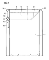
- Fig 4 shows a wall view of a corner of the casing 1 embodying the invention.
- the joint flange 13 is forming a butt joint 19 with the lateral wall 5.
- the joint flange 13 and the lateral wall 5 are cut in such a way that the butt joint 21 extends partially in a bevel 21 towards the upper front edge 20.
- the upper front edge 20 is formed by the front wall 2, the lateral wall 5 and the longitudinal wall 6.
- the retaining portion 9 and the bending of the retaining portion 16 are shown in cooperation with the fastening portion 10, the bending of the fastening portion 15 and the fastening leg 12.
- the fastening leg 12 engages into the retaining recess 11, which is not visible in this view, and thereby the fastening portion 15 is entangled with the retaining portion.
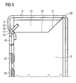
- Fig 5 shows a sectional wall view of a corner of the casing 1 embodying the invention.
- Fig 4 there is shown the lateral wall 5 and the longitudinal wall 6 and the upper front edge 20.
- the retaining portion 9 and the fastening portion 10 are now completely visible.
- the fastening leg 12 engages into the retaining recess 11.
- a force is applied by the fastening leg 12, when it is in contact with the retaining portion 9.
Landscapes
- Engineering & Computer Science (AREA)
- Microelectronics & Electronic Packaging (AREA)
- Cookers (AREA)
- Casings For Electric Apparatus (AREA)
- Closures For Containers (AREA)
- Brushes (AREA)
- Dry Shavers And Clippers (AREA)
Abstract
Description
- The present invention relates to a casing for a front cover of a household appliance, having at least one front wall, one longitudinal wall and one lateral wall, wherein the front wall, the longitudinal wall and the lateral wall form a corner of the casing, the longitudinal wall comprises a longitudinal flange and the lateral wall comprises a lateral flange and wherein at least one retaining portion is provided on one of the flanges and at least one fastening portion is provided on the other flange.
-
DE 10 2004 012 253 A1 describes a casing made of bendable material, comprising a bottom wall and side walls arranged rectangular to the bottom wall, characterized in that the side walls comprise in the region of the upper corners a flange, that is bent off rectangular and extending parallel to the bottom wall, wherein flange and side walls or only the flange comprise recesses wherein lugs equal in form engage for fixation of the side walls. Such an arrangement has to be carried out very precisely and does not comprise any possibility to adjust the side walls and the bottom walls relative to each other. Therefore the tolerances for the lugs and the recesses have to be met precisely. Furthermore the lugs and recesses would be at least partially visible for a user, which would cause an unaesthetic appearance. -
DE 10 2007 031 479 A1 describes a household appliance, provided with at least one operation module, which has at least one operation cover made from a metallic material. The operation cover is formed seamless. Such an arrangement does also not comprise any parts for adjusting the positions of the front portion and the top portion of the operation cover relative to each other. Furthermore the operation cover is designed especially for a bending with a larger radius. -
DE 196 49 047 C2 describes a household appliance having an operation cover with a front surface where at least one operation element for operating the household appliance is arrangeable and with at least one fastening element, which is arranged behind the front surface and covered in the viewing direction to the front surface, and a supporting arrangement for supporting the at least one fastening element of the operation cover. Such an operation cover also does not comprise means for adjusting the side walls and the front wall relative to each other. - In all known casings, front covers or operation panels described in the aforementioned documents, there are no means or arrangements for stabilising the corner of a casing in a way that adjustment of the relative positions of the front wall and the lateral walls is enabled.
- An object of the present invention is to create an improved casing of the said kind.
- A solution of this object according to the invention is defined and characterized by a casing according to claim 1 and a method for producing a casing according to
claim 10. The dependent claims refer to further embodiments of the present invention. - According to the present invention the fastening portion comprises a fastening leg, that is extending angular relative to the planes defined by the flanges and the retaining portion comprises a retaining recess that is extending relative to the planes defined by the flanges, whereas the fastening leg engages into the retaining recess and applies a force to the retaining portion, so that the lateral wall, the longitudinal wall and the front wall are fixed in their position relative to each other. Thus, the corner of the casing, that is formed by the lateral wall, the longitudinal wall and the front wall is stabilized and the walls are fixed in their position relative to each other. The worker is enabled to adjust the positions of the walls relative to each other by varying the applied force. An arrangement of the walls in a precise way can be achieved even when the precut metal sheet is not meeting the tolerances.
- According to advantageous embodiment of the invention the lateral flange and/or the longitudinal flange extend substantially parallel to the front wall. Parallel extension of the flanges simplifies the production of the casing and makes it easier to adjust the walls in their positions relative to each other.
- According to an advantageous embodiment of the invention the lateral wall, the longitudinal wall and the front wall are fixed in a rectangular position relative to each other. For the use of the casing within the visible front of a household appliance, a precise rectangular form of the casing is ideal. Also other forms, depending on the desired design, are imaginable and can be realized by the use of the present invention.
- According to another advantageous embodiment of the invention the force is adjusted to the material the cover is made of. The force can be determined according to the material the cover is made of or to the coating of the material. Different materials can be employed such as stainless steel, galvanized or precoated metals or plastics.
- According to another advantageous embodiment of the invention the longitudinal wall comprises a joint flange that is bent off rectangular into a recess comprised by the lateral wall and that is forming a butt joint with the lateral wall. Having such a joint flange and butt joint, the corner between lateral wall and longitudinal wall is not provided with the ends of the lateral wall and the longitudinal wall meeting at the corner. There is provided a transition at the corner with a bending radius comprised by the joint flange and the ends of the lateral wall and the longitudinal wall are meeting in a butt joint. Thus, the ends are not visible for a user and protected from corrosion.
- According to a further advantageous embodiment of the invention the force is adjusted in such a way, that the butt joint is formed without a gap. The forming of the butt joint without a gap improves the protection from corrosion even more. Further the interior of the casing is protected from the ingress of moisture or filth or the like.
- According to another advantageous embodiment of the invention the lateral flange and/or the longitudinal flange comprise one or more connection elements for connecting electronic components or operating buttons or the like to the casing or for connecting the casing to the household appliance. By means of such connection elements the casing can be mounted to a household appliance whereas the connection elements are not visible. Easy mounting of additional devices such as electronic components or operating buttons is enabled.
- According to a further advantageous embodiment of the invention the connection element or connection elements for connecting the casing to another component or the household appliance are provided with at least one embossment for stabilizing the connection. Such embossments reinforce the structure of the casing and simultaneously the connection of the casing to the household appliance.
- According to another advantageous embodiment of the invention the bending of the longitudinal wall and/or the upper front edge comprise a radius equal or smaller than twice the thickness of the metal sheet at these positions. Corners of casings that have a radius equal or smaller than twice the thickness of the wall that is bended at this positions give the designer a wide range of possibilities to adapt the appearance of the casing to the design of the household appliance. Small radii usually give an elegant impression and a good haptic.
- According to another advantageous embodiment of the invention the fastening leg and the retaining recess extend into the interior of the casing. Thus, the back wall of the casing can be mounted to the household appliance without forming a gap between the casing and the household appliance.
- According to another the force that is applied by the fastening leg to the retaining portion is a predefined resilient force. Parts like the walls of the casing that are established by bending processes comprises always resilient forces which take effect in opposition to the bending direction. Taken this effect into account before, the resilient force of the fastening leg can be predefined. Thus, the exact positioning of the walls can be achieved.
- An alternative solution for the object is given by the method for forming a front cover of a household appliance, comprising the steps die cutting of one metal sheet to two-dimensional structure, wherein at least one retaining portion having a recess and one fastening portion having a fastening leg are produced, bending for constituting lateral walls, longitudinal walls, lateral flanges and longitudinal flanges, wherein at least one corner is constituted comprising the recess and the fastening leg, engaging of the fastening leg into the recess by a bending operation, wherein a defined force is applied to the fastening leg, so that the joint between longitudinal wall and lateral wall is formed without a gap. This solution comprises a method for producing a casing with low costs and enabling an arrangement of the walls in a precise way.
- According to a further advantageous embodiment of the present invention the force to be applied to the fastening leg is defined after measuring dimensions and positions of the fastening leg and the recess. Thus, tolerances can be compensated by determining the applied force according to a preceding measurement.
- An embodiment of the invention is further disclosed by the following description according to the drawings.
-
Fig 1 is a perspective view of a casing, in particular for the use as a front cover of a household appliance showing a front side as well as a back side; -
Fig 2 is a rear view of a casing embodying the invention, showing a corner of the casing in an assembled state; -
Fig 3 is an enlarged view of a corner according toFig 2 embodying the invention; -
Fig 4 is a wall view from the left of a casing embodying the invention; -
Fig 5 is sectional wall view from the left according toFig 4 ; - In
Fig 1 it is shown afront side 4 and aback side 3 of a casing 1, wherein thefront side 4 is forming thefront wall 2. The casing 1 comprises alateral wall 5 and alongitudinal wall 6, wherein thelateral wall 5 has alateral flange 7 and thelongitudinal wall 6 has alongitudinal flange 8. Thelateral flange 7 and thelongitudinal flange 8 are extending substantially parallel to thefront wall 2, respectively to theback wall 3 of the casing 1. Thus, the casing 1 constitutes a box like form. Both flanges are extending substantially parallel to thefront wall 2, respectively to theback wall 3. Further it is shown ajoint flange 13, which is described later. -
Fig 2 shows the back side of a casing 1 having thelateral wall 5, thelongitudinal wall 6, thelateral flange 7 and thelongitudinal flange 8. Afastening portion 10 is arranged on thelateral flange 7 and a retainingportion 9 is arranged on thelongitudinal flange 8. A retainingrecess 11 is provided by the retainingportion 9 and afastening leg 12 is provided by thefastening portion 10. -
Fig 3 shows the embodiment according toFig 2 in a closer view. Thelateral flange 7 comprises afastening portion 10, that is provided with afastening leg 12. Thefastening portion 10 is bent off at the bending of thefastening portion 15 into the interior of the casing 1, whereby thefastening leg 12 is defined by the part of thefastening portion 10, which is bent off. Thelongitudinal flange 8 comprises a retainingportion 9, that is provided with a retainingrecess 11. The dimensions of the retainingrecess 11 are adapted to the dimensions of thefastening leg 12. The retainingportion 9 is bent off at the bending of the retainingportion 16, whereby the retainingrecess 11 is comprised partially within the part of the retainingportion 9, that is bent off. This part is also bent off into the interior of the casing 1. - The
longitudinal wall 6 is provided with ajoint flange 13, that that is bent off at the bending of thelongitudinal wall 14. Thejoint flange 13 forms a butt joint 19 with thelateral wall 5. Thelateral flange 7 comprises aconnection element 17 for connecting the casing 1 to another component or to a household appliance. Theconnection element 17 comprises a hole for a screw connection, but also other connection methods can be provided. Thelateral flange 7 furthermore comprisesembossments 18 for stabilizing the casing 1, in particular for stabilizing the connection of the casing 1 to the household appliance. -
Fig 4 shows a wall view of a corner of the casing 1 embodying the invention. There is shown thelateral wall 5 and thelongitudinal wall 6, wherein thelongitudinal wall 6 is provided with ajoint flange 13. Thejoint flange 13 is forming a butt joint 19 with thelateral wall 5. Thejoint flange 13 and thelateral wall 5 are cut in such a way that the butt joint 21 extends partially in abevel 21 towards the upperfront edge 20. The upperfront edge 20 is formed by thefront wall 2, thelateral wall 5 and thelongitudinal wall 6. The retainingportion 9 and the bending of the retainingportion 16 are shown in cooperation with thefastening portion 10, the bending of thefastening portion 15 and thefastening leg 12. Thefastening leg 12 engages into the retainingrecess 11, which is not visible in this view, and thereby thefastening portion 15 is entangled with the retaining portion. -
Fig 5 shows a sectional wall view of a corner of the casing 1 embodying the invention. As inFig 4 there is shown thelateral wall 5 and thelongitudinal wall 6 and the upperfront edge 20. Because of the section thejoint flange 13 and the butt joint 19 are now comprised corresponding on the other wall of the casing 1. The retainingportion 9 and thefastening portion 10 are now completely visible. Thefastening leg 12 engages into the retainingrecess 11. Depending on the dimensions of thefastening leg 12 and the retainingrecess 11 as well as on their angles relative to the planes defined by the planar extension of thefastening portion 10 and the retainingportion 9, a force is applied by thefastening leg 12, when it is in contact with the retainingportion 9. This force causes a traction in such a way that thejoint flange 13 and thelateral wall 5 are pressed together at the butt joint 19. When the force is strong enough, the butt joint 19 is provided without a gap. Furthermore there are shown embossments 18, that are comprised by thelateral flange 7. - The elements shown in the figures are designated as follows:
- 1
- casing
- 2
- front wall
- 3
- back side
- 4
- front side
- 5
- lateral wall
- 6
- longitudinal wall
- 7
- lateral flange
- 8
- longitudinal flange
- 9
- retaining portion
- 10
- fastening portion
- 11
- retaining recess
- 12
- fastening leg
- 13
- joint flange
- 14
- bending of the longitudinal wall
- 15
- bending of the fastening portion
- 16
- bending of the retaining portion
- 17
- connection element
- 18
- embossment
- 19
- butt joint
- 20
- upper front edge
- 21
- bevel
Claims (13)
- Casing (1) for a front cover of a household appliance, having at least one front wall (2), one longitudinal wall (6) and one lateral wall (5), wherein the front wall (2), the longitudinal wall (6) and the lateral wall (5) form a corner of the casing, the longitudinal wall (6) comprises a longitudinal flange (8) and the lateral wall (5) comprises a lateral flange (7) and wherein at least one retaining portion (9) is provided on one of the flanges and at least one fastening portion (10) is provided on the other flange, characterized in that
the fastening portion (10) comprises a fastening leg (12), arranged at an angle relative to planes defined by the flanges (7, 8) and the retaining portion (9) comprises a retaining recess (11) arranged at an angle relative to planes defined by the flanges (7, 8),
whereas the fastening leg (12) engages into the retaining recess (11) and applies a force to the retaining portion (9), so that the lateral wall (5), the longitudinal wall (6) and the front wall (2) are fixed in their position relative to each other. - Casing according to claim 1, characterized in that the lateral flange (7) and/or the longitudinal flange (8) extend substantially parallel to the front wall (2).
- Casing according to one of the preceding claims, characterized in that
the lateral wall (5), the longitudinal wall (6) and the front wall (2) are fixed in a orthogonal position relative to each other. - Casing according to one of the preceding claims, characterized in that
the force is adjusted to the material the cover is made of. - Casing according to one of the preceding claims, characterized in that
the longitudinal wall (6) comprises a joint flange (13) that is bent off orthogonal into a recess comprised by the lateral wall (5) and that forms a butt joint (19) with the lateral wall (5). - Casing according to claim 5, characterized in that the force is adjusted in such a way, that the butt joint (19) is formed without a gap.
- Casing according to one of the preceding claims, characterized in that
the lateral flange (7) and/or the longitudinal flange (8) comprise one or more connection elements (17) for connecting electronic components or operating buttons or the like to the casing or for connecting the casing (1) to the household appliance. - Casing according to claim 7, characterized in that the connection element or connection elements for connecting the casing to another component or the household appliance are provided with at least one embossment (18) for stabilizing the connection.
- Casing according to one of the preceding claims, characterized in that
the bending of the longitudinal wall (14) and/or the upper front edge (20) comprise a radius of curvature equal or smaller than twice the thickness of the wall that is bent at this positions. - Casing according to one of the preceding claims, characterized in that
the fastening leg (12) and the retaining recess (11) at least partially extend into the interior of the casing. - Casing according to one of the preceding claims, characterized in that the force that is applied by the fastening leg (12) to the retaining portion (9) is a predefined resilient force.
- Method for forming a front cover of a household appliance, comprising the following steps:- die cutting of one metal piece to a two-dimensional structure, wherein at least one retaining portion having a recess and one fastening portion having a fastening leg are produced- bending the metal sheet for constituting a front wall, lateral walls, longitudinal walls, lateral flanges and longitudinal flanges, wherein at least one corner is constituted comprising the recess and the fastening leg- engaging of the fastening leg into the recess by a bending operation, wherein a defined force is applied to the fastening leg, so that the joint between longitudinal wall and lateral wall is formed without a gap.
- Method according to claim 11, wherein
the force to be applied to the fastening leg is defined after measuring dimensions and positions of the fastening leg and the recess.
Priority Applications (4)
| Application Number | Priority Date | Filing Date | Title |
|---|---|---|---|
| DE602009000724T DE602009000724D1 (en) | 2009-06-29 | 2009-06-29 | Housing for the front cover of a household appliance |
| PL09008476T PL2271195T3 (en) | 2009-06-29 | 2009-06-29 | Casing for a front cover of a household appliance |
| EP09008476A EP2271195B1 (en) | 2009-06-29 | 2009-06-29 | Casing for a front cover of a household appliance |
| AT09008476T ATE498298T1 (en) | 2009-06-29 | 2009-06-29 | HOUSING FOR THE FRONT COVER OF A HOUSEHOLD APPLIANCE |
Applications Claiming Priority (1)
| Application Number | Priority Date | Filing Date | Title |
|---|---|---|---|
| EP09008476A EP2271195B1 (en) | 2009-06-29 | 2009-06-29 | Casing for a front cover of a household appliance |
Publications (2)
| Publication Number | Publication Date |
|---|---|
| EP2271195A1 true EP2271195A1 (en) | 2011-01-05 |
| EP2271195B1 EP2271195B1 (en) | 2011-02-09 |
Family
ID=41259064
Family Applications (1)
| Application Number | Title | Priority Date | Filing Date |
|---|---|---|---|
| EP09008476A Not-in-force EP2271195B1 (en) | 2009-06-29 | 2009-06-29 | Casing for a front cover of a household appliance |
Country Status (4)
| Country | Link |
|---|---|
| EP (1) | EP2271195B1 (en) |
| AT (1) | ATE498298T1 (en) |
| DE (1) | DE602009000724D1 (en) |
| PL (1) | PL2271195T3 (en) |
Citations (5)
| Publication number | Priority date | Publication date | Assignee | Title |
|---|---|---|---|---|
| FR2419651A1 (en) * | 1978-03-07 | 1979-10-05 | Telemecanique Electrique | Electrical chassis or enclosure - is formed by interlocking folded and pressed sides in single metal sheet |
| DE19649047C2 (en) | 1996-11-27 | 1998-09-10 | Juno Kuechentech Electrolux | Household appliance with a control panel which is fastened with fastening elements which are not visible from the front |
| US20040124194A1 (en) * | 2002-12-31 | 2004-07-01 | Sam Beizai | Electro-magnetic interference shield with locking latch |
| DE102004012253A1 (en) | 2004-03-12 | 2005-09-29 | Heinrich Ziegler Gmbh | Metal casing, has side walls that are at right angles to bottom wall, and side parallel to bottom wall, where side walls and side or only side has recess in which latches for fixing side walls are inserted |
| DE102007031479A1 (en) | 2007-07-06 | 2009-01-08 | BSH Bosch und Siemens Hausgeräte GmbH | Water-bearing household appliance e.g. dishwasher, for use in kitchen, has control module with control panel made of metallic material i.e. stainless steel, where control panel is formed in seamless connection manner |
-
2009
- 2009-06-29 AT AT09008476T patent/ATE498298T1/en not_active IP Right Cessation
- 2009-06-29 DE DE602009000724T patent/DE602009000724D1/en active Active
- 2009-06-29 EP EP09008476A patent/EP2271195B1/en not_active Not-in-force
- 2009-06-29 PL PL09008476T patent/PL2271195T3/en unknown
Patent Citations (5)
| Publication number | Priority date | Publication date | Assignee | Title |
|---|---|---|---|---|
| FR2419651A1 (en) * | 1978-03-07 | 1979-10-05 | Telemecanique Electrique | Electrical chassis or enclosure - is formed by interlocking folded and pressed sides in single metal sheet |
| DE19649047C2 (en) | 1996-11-27 | 1998-09-10 | Juno Kuechentech Electrolux | Household appliance with a control panel which is fastened with fastening elements which are not visible from the front |
| US20040124194A1 (en) * | 2002-12-31 | 2004-07-01 | Sam Beizai | Electro-magnetic interference shield with locking latch |
| DE102004012253A1 (en) | 2004-03-12 | 2005-09-29 | Heinrich Ziegler Gmbh | Metal casing, has side walls that are at right angles to bottom wall, and side parallel to bottom wall, where side walls and side or only side has recess in which latches for fixing side walls are inserted |
| DE102007031479A1 (en) | 2007-07-06 | 2009-01-08 | BSH Bosch und Siemens Hausgeräte GmbH | Water-bearing household appliance e.g. dishwasher, for use in kitchen, has control module with control panel made of metallic material i.e. stainless steel, where control panel is formed in seamless connection manner |
Also Published As
| Publication number | Publication date |
|---|---|
| ATE498298T1 (en) | 2011-02-15 |
| EP2271195B1 (en) | 2011-02-09 |
| DE602009000724D1 (en) | 2011-03-24 |
| PL2271195T3 (en) | 2011-09-30 |
Similar Documents
| Publication | Publication Date | Title |
|---|---|---|
| US8975519B2 (en) | Adjustable bracket for steel stud | |
| CN206213617U (en) | Drawer wall element and furniture with the drawer wall element | |
| CA2597186A1 (en) | Fastening member and external wall construction structure using the same | |
| EP2772693B1 (en) | Encasing for household appliances | |
| EP2271195B1 (en) | Casing for a front cover of a household appliance | |
| JP2010007301A (en) | Structure of trim for face panel | |
| JP4857935B2 (en) | Shield structure | |
| JP2005068878A (en) | Joint structure of exterior material | |
| CN104363793A (en) | Drawer rear wall | |
| JP6681671B2 (en) | Drawers and cabinets with drawers | |
| KR100933899B1 (en) | Wall plate | |
| JP3619768B2 (en) | Cooker | |
| JP6163628B2 (en) | Cover member assembly structure | |
| JP4098754B2 (en) | End piece mounting structure for drop-in stove | |
| JP4438765B2 (en) | Exterior panel accessory | |
| JP5540998B2 (en) | Top plate side edge mounting structure | |
| JP5462757B2 (en) | Ventilation eave ceiling parting edge and ventilation outer wall structure | |
| JP5582840B2 (en) | Split-type bathtub apron | |
| EP2390583B1 (en) | A casing for a domestic appliance and a method for assembling a casing | |
| JP4838186B2 (en) | cabinet | |
| KR101758683B1 (en) | Case for installing electronic components | |
| JP2018153038A (en) | Assembly structure of decoration member | |
| JP5473881B2 (en) | refrigerator | |
| EP3742090A1 (en) | Door-integrated handle assembly for a refrigerator door | |
| EP2796792B1 (en) | High-frequency heating device |
Legal Events
| Date | Code | Title | Description |
|---|---|---|---|
| GRAP | Despatch of communication of intention to grant a patent |
Free format text: ORIGINAL CODE: EPIDOSNIGR1 |
|
| PUAI | Public reference made under article 153(3) epc to a published international application that has entered the european phase |
Free format text: ORIGINAL CODE: 0009012 |
|
| GRAS | Grant fee paid |
Free format text: ORIGINAL CODE: EPIDOSNIGR3 |
|
| 17P | Request for examination filed |
Effective date: 20100112 |
|
| AK | Designated contracting states |
Kind code of ref document: A1 Designated state(s): AT BE BG CH CY CZ DE DK EE ES FI FR GB GR HR HU IE IS IT LI LT LU LV MC MK MT NL NO PL PT RO SE SI SK TR |
|
| AX | Request for extension of the european patent |
Extension state: AL BA RS |
|
| GRAA | (expected) grant |
Free format text: ORIGINAL CODE: 0009210 |
|
| AK | Designated contracting states |
Kind code of ref document: B1 Designated state(s): AT BE BG CH CY CZ DE DK EE ES FI FR GB GR HR HU IE IS IT LI LT LU LV MC MK MT NL NO PL PT RO SE SI SK TR |
|
| REG | Reference to a national code |
Ref country code: GB Ref legal event code: FG4D |
|
| REG | Reference to a national code |
Ref country code: CH Ref legal event code: EP |
|
| REG | Reference to a national code |
Ref country code: IE Ref legal event code: FG4D |
|
| RAP2 | Party data changed (patent owner data changed or rights of a patent transferred) |
Owner name: ELECTROLUX HOME PRODUCTS CORPORATION N.V. |
|
| REF | Corresponds to: |
Ref document number: 602009000724 Country of ref document: DE Date of ref document: 20110324 Kind code of ref document: P |
|
| REG | Reference to a national code |
Ref country code: DE Ref legal event code: R096 Ref document number: 602009000724 Country of ref document: DE Effective date: 20110324 |
|
| REG | Reference to a national code |
Ref country code: DE Ref legal event code: R081 Ref document number: 602009000724 Country of ref document: DE Owner name: ELECTROLUX HOME PRODUCTS CORPORATION N.V., BE Free format text: FORMER OWNER: ELECTROLUX HOME PRODUCTS CORPORATION N.V., ZAVENTEM, BE Effective date: 20110208 |
|
| REG | Reference to a national code |
Ref country code: SE Ref legal event code: TRGR |
|
| REG | Reference to a national code |
Ref country code: NL Ref legal event code: VDEP Effective date: 20110209 |
|
| RAP2 | Party data changed (patent owner data changed or rights of a patent transferred) |
Owner name: ELECTROLUX HOME PRODUCTS CORPORATION N.V. |
|
| LTIE | Lt: invalidation of european patent or patent extension |
Effective date: 20110209 |
|
| PG25 | Lapsed in a contracting state [announced via postgrant information from national office to epo] |
Ref country code: PT Free format text: LAPSE BECAUSE OF FAILURE TO SUBMIT A TRANSLATION OF THE DESCRIPTION OR TO PAY THE FEE WITHIN THE PRESCRIBED TIME-LIMIT Effective date: 20110609 Ref country code: LV Free format text: LAPSE BECAUSE OF FAILURE TO SUBMIT A TRANSLATION OF THE DESCRIPTION OR TO PAY THE FEE WITHIN THE PRESCRIBED TIME-LIMIT Effective date: 20110209 Ref country code: ES Free format text: LAPSE BECAUSE OF FAILURE TO SUBMIT A TRANSLATION OF THE DESCRIPTION OR TO PAY THE FEE WITHIN THE PRESCRIBED TIME-LIMIT Effective date: 20110520 Ref country code: NO Free format text: LAPSE BECAUSE OF FAILURE TO SUBMIT A TRANSLATION OF THE DESCRIPTION OR TO PAY THE FEE WITHIN THE PRESCRIBED TIME-LIMIT Effective date: 20110509 Ref country code: LT Free format text: LAPSE BECAUSE OF FAILURE TO SUBMIT A TRANSLATION OF THE DESCRIPTION OR TO PAY THE FEE WITHIN THE PRESCRIBED TIME-LIMIT Effective date: 20110209 Ref country code: HR Free format text: LAPSE BECAUSE OF FAILURE TO SUBMIT A TRANSLATION OF THE DESCRIPTION OR TO PAY THE FEE WITHIN THE PRESCRIBED TIME-LIMIT Effective date: 20110209 Ref country code: GR Free format text: LAPSE BECAUSE OF FAILURE TO SUBMIT A TRANSLATION OF THE DESCRIPTION OR TO PAY THE FEE WITHIN THE PRESCRIBED TIME-LIMIT Effective date: 20110510 |
|
| PG25 | Lapsed in a contracting state [announced via postgrant information from national office to epo] |
Ref country code: FI Free format text: LAPSE BECAUSE OF FAILURE TO SUBMIT A TRANSLATION OF THE DESCRIPTION OR TO PAY THE FEE WITHIN THE PRESCRIBED TIME-LIMIT Effective date: 20110209 Ref country code: BG Free format text: LAPSE BECAUSE OF FAILURE TO SUBMIT A TRANSLATION OF THE DESCRIPTION OR TO PAY THE FEE WITHIN THE PRESCRIBED TIME-LIMIT Effective date: 20110509 Ref country code: SI Free format text: LAPSE BECAUSE OF FAILURE TO SUBMIT A TRANSLATION OF THE DESCRIPTION OR TO PAY THE FEE WITHIN THE PRESCRIBED TIME-LIMIT Effective date: 20110209 Ref country code: NL Free format text: LAPSE BECAUSE OF FAILURE TO SUBMIT A TRANSLATION OF THE DESCRIPTION OR TO PAY THE FEE WITHIN THE PRESCRIBED TIME-LIMIT Effective date: 20110209 Ref country code: BE Free format text: LAPSE BECAUSE OF FAILURE TO SUBMIT A TRANSLATION OF THE DESCRIPTION OR TO PAY THE FEE WITHIN THE PRESCRIBED TIME-LIMIT Effective date: 20110209 Ref country code: AT Free format text: LAPSE BECAUSE OF FAILURE TO SUBMIT A TRANSLATION OF THE DESCRIPTION OR TO PAY THE FEE WITHIN THE PRESCRIBED TIME-LIMIT Effective date: 20110209 Ref country code: CY Free format text: LAPSE BECAUSE OF FAILURE TO SUBMIT A TRANSLATION OF THE DESCRIPTION OR TO PAY THE FEE WITHIN THE PRESCRIBED TIME-LIMIT Effective date: 20110209 |
|
| REG | Reference to a national code |
Ref country code: PL Ref legal event code: T3 |
|
| PG25 | Lapsed in a contracting state [announced via postgrant information from national office to epo] |
Ref country code: EE Free format text: LAPSE BECAUSE OF FAILURE TO SUBMIT A TRANSLATION OF THE DESCRIPTION OR TO PAY THE FEE WITHIN THE PRESCRIBED TIME-LIMIT Effective date: 20110209 Ref country code: DK Free format text: LAPSE BECAUSE OF FAILURE TO SUBMIT A TRANSLATION OF THE DESCRIPTION OR TO PAY THE FEE WITHIN THE PRESCRIBED TIME-LIMIT Effective date: 20110209 |
|
| PG25 | Lapsed in a contracting state [announced via postgrant information from national office to epo] |
Ref country code: CZ Free format text: LAPSE BECAUSE OF FAILURE TO SUBMIT A TRANSLATION OF THE DESCRIPTION OR TO PAY THE FEE WITHIN THE PRESCRIBED TIME-LIMIT Effective date: 20110209 Ref country code: SK Free format text: LAPSE BECAUSE OF FAILURE TO SUBMIT A TRANSLATION OF THE DESCRIPTION OR TO PAY THE FEE WITHIN THE PRESCRIBED TIME-LIMIT Effective date: 20110209 Ref country code: RO Free format text: LAPSE BECAUSE OF FAILURE TO SUBMIT A TRANSLATION OF THE DESCRIPTION OR TO PAY THE FEE WITHIN THE PRESCRIBED TIME-LIMIT Effective date: 20110209 |
|
| PLBE | No opposition filed within time limit |
Free format text: ORIGINAL CODE: 0009261 |
|
| STAA | Information on the status of an ep patent application or granted ep patent |
Free format text: STATUS: NO OPPOSITION FILED WITHIN TIME LIMIT |
|
| PG25 | Lapsed in a contracting state [announced via postgrant information from national office to epo] |
Ref country code: MT Free format text: LAPSE BECAUSE OF FAILURE TO SUBMIT A TRANSLATION OF THE DESCRIPTION OR TO PAY THE FEE WITHIN THE PRESCRIBED TIME-LIMIT Effective date: 20110209 |
|
| 26N | No opposition filed |
Effective date: 20111110 |
|
| REG | Reference to a national code |
Ref country code: FR Ref legal event code: CA Effective date: 20120116 |
|
| REG | Reference to a national code |
Ref country code: DE Ref legal event code: R097 Ref document number: 602009000724 Country of ref document: DE Effective date: 20111110 |
|
| REG | Reference to a national code |
Ref country code: IE Ref legal event code: MM4A |
|
| PG25 | Lapsed in a contracting state [announced via postgrant information from national office to epo] |
Ref country code: IE Free format text: LAPSE BECAUSE OF NON-PAYMENT OF DUE FEES Effective date: 20110629 |
|
| REG | Reference to a national code |
Ref country code: DE Ref legal event code: R082 Ref document number: 602009000724 Country of ref document: DE Representative=s name: GERHARD BAUMGARTL, DE Ref country code: DE Ref legal event code: R082 Ref document number: 602009000724 Country of ref document: DE Representative=s name: BAUMGARTL, GERHARD, DIPL.-ING.UNIV., DE |
|
| PG25 | Lapsed in a contracting state [announced via postgrant information from national office to epo] |
Ref country code: MK Free format text: LAPSE BECAUSE OF FAILURE TO SUBMIT A TRANSLATION OF THE DESCRIPTION OR TO PAY THE FEE WITHIN THE PRESCRIBED TIME-LIMIT Effective date: 20110209 |
|
| PG25 | Lapsed in a contracting state [announced via postgrant information from national office to epo] |
Ref country code: MC Free format text: LAPSE BECAUSE OF NON-PAYMENT OF DUE FEES Effective date: 20110630 |
|
| PG25 | Lapsed in a contracting state [announced via postgrant information from national office to epo] |
Ref country code: LU Free format text: LAPSE BECAUSE OF NON-PAYMENT OF DUE FEES Effective date: 20110629 |
|
| PG25 | Lapsed in a contracting state [announced via postgrant information from national office to epo] |
Ref country code: IS Free format text: LAPSE BECAUSE OF FAILURE TO SUBMIT A TRANSLATION OF THE DESCRIPTION OR TO PAY THE FEE WITHIN THE PRESCRIBED TIME-LIMIT Effective date: 20110209 |
|
| PGFP | Annual fee paid to national office [announced via postgrant information from national office to epo] |
Ref country code: SE Payment date: 20130619 Year of fee payment: 5 |
|
| PG25 | Lapsed in a contracting state [announced via postgrant information from national office to epo] |
Ref country code: HU Free format text: LAPSE BECAUSE OF FAILURE TO SUBMIT A TRANSLATION OF THE DESCRIPTION OR TO PAY THE FEE WITHIN THE PRESCRIBED TIME-LIMIT Effective date: 20110209 |
|
| REG | Reference to a national code |
Ref country code: CH Ref legal event code: PL |
|
| PG25 | Lapsed in a contracting state [announced via postgrant information from national office to epo] |
Ref country code: LI Free format text: LAPSE BECAUSE OF NON-PAYMENT OF DUE FEES Effective date: 20130630 Ref country code: CH Free format text: LAPSE BECAUSE OF NON-PAYMENT OF DUE FEES Effective date: 20130630 |
|
| PG25 | Lapsed in a contracting state [announced via postgrant information from national office to epo] |
Ref country code: SE Free format text: LAPSE BECAUSE OF NON-PAYMENT OF DUE FEES Effective date: 20140630 |
|
| REG | Reference to a national code |
Ref country code: SE Ref legal event code: EUG |
|
| REG | Reference to a national code |
Ref country code: FR Ref legal event code: PLFP Year of fee payment: 8 |
|
| REG | Reference to a national code |
Ref country code: FR Ref legal event code: PLFP Year of fee payment: 9 |
|
| REG | Reference to a national code |
Ref country code: FR Ref legal event code: PLFP Year of fee payment: 10 |
|
| PGFP | Annual fee paid to national office [announced via postgrant information from national office to epo] |
Ref country code: FR Payment date: 20200619 Year of fee payment: 12 Ref country code: TR Payment date: 20200629 Year of fee payment: 12 Ref country code: DE Payment date: 20200618 Year of fee payment: 12 |
|
| PGFP | Annual fee paid to national office [announced via postgrant information from national office to epo] |
Ref country code: GB Payment date: 20200625 Year of fee payment: 12 Ref country code: PL Payment date: 20200619 Year of fee payment: 12 |
|
| PGFP | Annual fee paid to national office [announced via postgrant information from national office to epo] |
Ref country code: IT Payment date: 20200625 Year of fee payment: 12 |
|
| REG | Reference to a national code |
Ref country code: DE Ref legal event code: R119 Ref document number: 602009000724 Country of ref document: DE |
|
| GBPC | Gb: european patent ceased through non-payment of renewal fee |
Effective date: 20210629 |
|
| PG25 | Lapsed in a contracting state [announced via postgrant information from national office to epo] |
Ref country code: GB Free format text: LAPSE BECAUSE OF NON-PAYMENT OF DUE FEES Effective date: 20210629 Ref country code: DE Free format text: LAPSE BECAUSE OF NON-PAYMENT OF DUE FEES Effective date: 20220101 |
|
| PG25 | Lapsed in a contracting state [announced via postgrant information from national office to epo] |
Ref country code: FR Free format text: LAPSE BECAUSE OF NON-PAYMENT OF DUE FEES Effective date: 20210630 |
|
| PG25 | Lapsed in a contracting state [announced via postgrant information from national office to epo] |
Ref country code: TR Free format text: LAPSE BECAUSE OF NON-PAYMENT OF DUE FEES Effective date: 20210629 |
|
| PG25 | Lapsed in a contracting state [announced via postgrant information from national office to epo] |
Ref country code: IT Free format text: LAPSE BECAUSE OF NON-PAYMENT OF DUE FEES Effective date: 20210629 |
|
| PG25 | Lapsed in a contracting state [announced via postgrant information from national office to epo] |
Ref country code: PL Free format text: LAPSE BECAUSE OF NON-PAYMENT OF DUE FEES Effective date: 20210629 |