EP2270956A2 - Synchronous electric machine comprising a stator and at least one rotor and associated control device. - Google Patents
Synchronous electric machine comprising a stator and at least one rotor and associated control device. Download PDFInfo
- Publication number
- EP2270956A2 EP2270956A2 EP10177277A EP10177277A EP2270956A2 EP 2270956 A2 EP2270956 A2 EP 2270956A2 EP 10177277 A EP10177277 A EP 10177277A EP 10177277 A EP10177277 A EP 10177277A EP 2270956 A2 EP2270956 A2 EP 2270956A2
- Authority
- EP
- European Patent Office
- Prior art keywords
- rotor
- teeth
- stator
- machine
- permanent magnets
- Prior art date
- Legal status (The legal status is an assumption and is not a legal conclusion. Google has not performed a legal analysis and makes no representation as to the accuracy of the status listed.)
- Withdrawn
Links
Images

Classifications
-
- H—ELECTRICITY
- H02—GENERATION; CONVERSION OR DISTRIBUTION OF ELECTRIC POWER
- H02K—DYNAMO-ELECTRIC MACHINES
- H02K1/00—Details of the magnetic circuit
- H02K1/06—Details of the magnetic circuit characterised by the shape, form or construction
- H02K1/22—Rotating parts of the magnetic circuit
- H02K1/27—Rotor cores with permanent magnets
- H02K1/2706—Inner rotors
- H02K1/272—Inner rotors the magnetisation axis of the magnets being perpendicular to the rotor axis
- H02K1/274—Inner rotors the magnetisation axis of the magnets being perpendicular to the rotor axis the rotor consisting of two or more circumferentially positioned magnets
- H02K1/2753—Inner rotors the magnetisation axis of the magnets being perpendicular to the rotor axis the rotor consisting of two or more circumferentially positioned magnets the rotor consisting of magnets or groups of magnets arranged with alternating polarity
- H02K1/276—Magnets embedded in the magnetic core, e.g. interior permanent magnets [IPM]
- H02K1/2766—Magnets embedded in the magnetic core, e.g. interior permanent magnets [IPM] having a flux concentration effect
- H02K1/2773—Magnets embedded in the magnetic core, e.g. interior permanent magnets [IPM] having a flux concentration effect consisting of tangentially magnetized radial magnets
-
- H—ELECTRICITY
- H02—GENERATION; CONVERSION OR DISTRIBUTION OF ELECTRIC POWER
- H02K—DYNAMO-ELECTRIC MACHINES
- H02K21/00—Synchronous motors having permanent magnets; Synchronous generators having permanent magnets
- H02K21/12—Synchronous motors having permanent magnets; Synchronous generators having permanent magnets with stationary armatures and rotating magnets
- H02K21/14—Synchronous motors having permanent magnets; Synchronous generators having permanent magnets with stationary armatures and rotating magnets with magnets rotating within the armatures
- H02K21/16—Synchronous motors having permanent magnets; Synchronous generators having permanent magnets with stationary armatures and rotating magnets with magnets rotating within the armatures having annular armature cores with salient poles
-
- H—ELECTRICITY
- H02—GENERATION; CONVERSION OR DISTRIBUTION OF ELECTRIC POWER
- H02P—CONTROL OR REGULATION OF ELECTRIC MOTORS, ELECTRIC GENERATORS OR DYNAMO-ELECTRIC CONVERTERS; CONTROLLING TRANSFORMERS, REACTORS OR CHOKE COILS
- H02P27/00—Arrangements or methods for the control of AC motors characterised by the kind of supply voltage
- H02P27/04—Arrangements or methods for the control of AC motors characterised by the kind of supply voltage using variable-frequency supply voltage, e.g. inverter or converter supply voltage
- H02P27/045—Arrangements or methods for the control of AC motors characterised by the kind of supply voltage using variable-frequency supply voltage, e.g. inverter or converter supply voltage whereby the speed is regulated by measuring the motor speed and comparing it with a given physical value
-
- H—ELECTRICITY
- H02—GENERATION; CONVERSION OR DISTRIBUTION OF ELECTRIC POWER
- H02P—CONTROL OR REGULATION OF ELECTRIC MOTORS, ELECTRIC GENERATORS OR DYNAMO-ELECTRIC CONVERTERS; CONTROLLING TRANSFORMERS, REACTORS OR CHOKE COILS
- H02P27/00—Arrangements or methods for the control of AC motors characterised by the kind of supply voltage
- H02P27/04—Arrangements or methods for the control of AC motors characterised by the kind of supply voltage using variable-frequency supply voltage, e.g. inverter or converter supply voltage
- H02P27/06—Arrangements or methods for the control of AC motors characterised by the kind of supply voltage using variable-frequency supply voltage, e.g. inverter or converter supply voltage using dc to ac converters or inverters
- H02P27/08—Arrangements or methods for the control of AC motors characterised by the kind of supply voltage using variable-frequency supply voltage, e.g. inverter or converter supply voltage using dc to ac converters or inverters with pulse width modulation
-
- H—ELECTRICITY
- H02—GENERATION; CONVERSION OR DISTRIBUTION OF ELECTRIC POWER
- H02K—DYNAMO-ELECTRIC MACHINES
- H02K1/00—Details of the magnetic circuit
- H02K1/06—Details of the magnetic circuit characterised by the shape, form or construction
- H02K1/22—Rotating parts of the magnetic circuit
- H02K1/24—Rotor cores with salient poles ; Variable reluctance rotors
Landscapes
- Engineering & Computer Science (AREA)
- Power Engineering (AREA)
- Control Of Ac Motors In General (AREA)
- Permanent Magnet Type Synchronous Machine (AREA)
- Permanent Field Magnets Of Synchronous Machinery (AREA)
Abstract
Description
La présente invention concerne le domaine des machines électriques tournantes.The present invention relates to the field of rotating electrical machines.
L'invention concerne plus particulièrement mais non exclusivement les machines synchrones à aimants permanents pouvant fonctionner à puissance sensiblement constante sur une large plage de vitesses, par exemple les machines de levage ou de traction électrique.The invention relates more particularly but not exclusively to permanent magnet synchronous machines that can operate at a substantially constant power over a wide range of speeds, for example lifting or electric traction machines.
Dans le cadre du levage, il est utile d'adapter la vitesse de levage à la charge levée afin de réduire le temps de levage lorsque cette charge est faible tout en permettant d'assurer le levage des pièces plus lourdes.In the context of lifting, it is useful to adapt the lifting speed to the lifting load in order to reduce the lifting time when this load is low while allowing lifting of the heavier parts.
Dans le cadre de la traction électrique, au démarrage ou lorsque le véhicule aborde une montée, le moteur doit fournir un fort couple à basse vitesse. En revanche, sur un parcours horizontal, les efforts à fournir sont moindres, et le véhicule peut rouler plus vite sans nécessiter plus de puissance du moteur.In the case of electric traction, when starting or when the vehicle approaches a climb, the engine must provide a high torque at low speed. On the other hand, on a horizontal course, the efforts to be provided are smaller, and the vehicle can drive faster without requiring more engine power.
Les machines synchrones peuvent fonctionner à couple constant jusqu'à une certaine vitesse appelée vitesse de base. Jusqu'à cette vitesse de base, la puissance croit sensiblement proportionnellement à la vitesse de rotation du rotor. Au-delà de la vitesse de base, le couple diminue à puissance sensiblement constante.Synchronous machines can operate at constant torque up to a certain speed called base speed. Up to this basic speed, the power increases substantially in proportion to the speed of rotation of the rotor. Beyond the base speed, the torque decreases at substantially constant power.
Les phases de l'induit peuvent être modélisées chacune par une inductance qui regroupe les termes d'auto-induction, de mutuelles entre phases et de fuite. Cette inductance dépend de la position angulaire du rotor relativement au stator, et a pour composantes dans un repère lié à la pulsation électrique l'inductance directe Ld et l'inductance en quadrature Lq. La réactance directe Xd désigne le produit de l'inductance directe Ld par la pulsation électrique ω, et la réactance en quadrature Xq désigne le produit de l'inductance Lq en quadrature par la pulsation électrique ω. La vitesse de rotation du rotor Ω est liée à la pulsation électrique ω par la relation ω = zΩ, où z désigne le nombre de paires de pôles.The phases of the armature can each be modeled by an inductance which groups together the terms of self-induction, phase mutuals and leakage. This inductance depends on the angular position of the rotor relative to the stator, and its components in a reference linked to the electrical pulsation the direct inductance L d and the quadrature inductance L q . The direct reactance X d designates the product of the direct inductance L d by the electric pulsation ω, and the quadrature reactance X q designates the product of the inductance Lq in quadrature by the electric pulsation ω. The speed of rotation of the rotor Ω is related to the electric pulsation ω by the relation ω = zΩ, where z denotes the number of pairs of poles.
Dans le repère lié à la pulsation électrique, l'inductance directe Ld d'une phase de l'induit est la valeur de l'inductance dans l'axe d dit direct, c'est-à-dire lorsque l'axe des pôles inducteurs coïncide avec celui des bobines du stator de cette même phase. L'inductance en quadrature Lq est la valeur de l'inductance dans l'axe q dit en quadrature, c'est-à-dire quand l'axe des pôles inducteurs est perpendiculaire à l'axe des bobines du stator pour cette même phase.In the reference linked to the electrical pulsation, the direct inductance L d of a phase of the armature is the value of the inductance in the direct d axis, that is to say when the axis of the Inductor poles coincide with that of the stator coils of this same phase. The quadrature inductance Lq is the value of the inductance in the quadrature q axis, that is to say when the axis of the inductive poles is perpendicular to the axis of the stator coils for this same phase.
Les machines électriques tournantes à aimants permanents connues pour le levage et la traction électrique sont majoritairement des machines dites à pôles lisses, pour lesquelles la réactance directe Xd est sensiblement égale à la réactance en quadrature Xq.The rotating electric machines with permanent magnets known for lifting and electric traction are mostly so-called smooth-poles machines, for which the direct reactance X d is substantially equal to the quadrature reactance X q .
En plus des machines à pôles lisses, on trouve aussi des machines dites à saillance inversée, pour lesquelles la réactance directe Xd est nettement inférieure à la réactance en quadrature Xq. Leur principal avantage est que le couple de réluctance, qui est proportionnel à la différence entre les réactances Xq et Xd, s'ajoute, en fonctionnement normal, au couple de force électromotrice généré par les aimants, ce qui permet, à couple demandé identique, de réduire le volume des aimants et donc le prix de la machine. Pour ce type de machine, il existe un décalage optimal en avance de phase du courant par rapport à la force électromotrice pour lequel le couple est maximal. C'est ce point de fonctionnement qui est retenu jusqu'à la vitesse de base.In addition to machines with smooth poles, there are also so-called inverted saliency machines, for which the direct reactance X d is much smaller than the quadrature reactance X q . Their main advantage is that the reluctance torque, which is proportional to the difference between the reactances X q and X d , is added, in normal operation, to the electromotive force torque generated by the magnets, which makes it possible, at the requested torque identical, reduce the volume of magnets and therefore the price of the machine. For this type of machine, there is an optimal offset in phase advance of the current with respect to the electromotive force for which the torque is maximum. It is this operating point that is held up to the base speed.
Au-delà de la vitesse de base, la tension aux bornes des phases de la machine devient toutes choses égales par ailleurs supérieure à la tension disponible fournie par le réseau à la machine par l'intermédiaire du dispositif de commande, en raison de la force électromotrice qui varie proportionnellement à la vitesse.Beyond the base speed, the voltage across the phases of the machine becomes all other things equal higher than the available voltage supplied by the network to the machine through the control device, due to the force electromotive which varies in proportion to the speed.
Pour réduire la tension aux bornes des phases de la machine, on agit sur le courant dans les enroulements du stator et sur son déphasage par rapport au flux inducteur, c'est-à-dire celui des aimants, pour créer un flux magnétique s'opposant partiellement au flux inducteur. Cette opération est appelée « défluxage » et génère des pertes électriques d'autant plus importantes que le courant nécessaire au défluxage est élevé.To reduce the voltage across the phases of the machine, it acts on the current in the stator windings and on its phase shift with respect to the inductor flux, that is to say that of the magnets, to create a magnetic flux s' partially opposing the inducing flux. This operation is called "defluxing" and generates electrical losses all the more important as the current required for defluxing is high.
Il existe un besoin pour améliorer les machines synchrones et leur permettre de fonctionner avec un rendement élevé à puissance sensiblement constante sur une large plage de vitesses, et notamment au-delà de la vitesse de base.There is a need to improve synchronous machines and enable them to operate with high efficiency at substantially constant power over a wide range of speeds, and especially beyond basic speed.
L'invention répond à ce besoin grâce à une machine électrique synchrone comportant un stator et au moins un rotor à aimants permanents, la machine se caractérisant par le fait qu'elle est agencée de manière à avoir Xd > Xq,
où Xd est la réactance directe et Xq la réactance en quadrature. On a par exemple Xd/Xq> 1,1, mieux Xd/Xq > 1,5. On peut avoir par exemple Xd/Xq≅ 3.The invention responds to this need by means of a synchronous electric machine comprising a stator and at least one rotor with permanent magnets, the machine being characterized in that it is arranged so as to have X d > X q ,
where X d is the direct reactance and X q is the quadrature reactance. For example, X d / X q > 1.1, better X d / X q > 1.5. We can have for example X d / X q ≅ 3.
Les avantages apportés par l'invention sont les suivants.The advantages provided by the invention are as follows.
D'une part, le facteur de puissance cos φ variant en sens inverse de la réactance en quadrature Xq, une faible valeur de Xq permet d'obtenir un facteur de puissance élevé. On a par exemple, suivant le niveau de facteur de puissance recherché, Xq Io/E compris entre 0,33 et 0,6, où Io désigne l'intensité maximale du courant de ligne imposée par le calibre du variateur et E la force électromotrice induite par phase de la machine.On the one hand, the power factor cos φ varying in the opposite direction of the quadrature reactance X q , a low value of X q makes it possible to obtain a high power factor. For example, according to the desired power factor level, X q I o / E between 0.33 and 0.6, where I o denotes the maximum intensity of the line current imposed by the dimming of the drive and E the phase-induced electromotive force of the machine.
D'autre part, le flux des aimants étant orienté dans l'axe d direct, le défluxage s'effectue en injectant dans l'induit un courant de manière à générer dans l'axe direct d un flux proportionnel à la réactance directe Xd et à la composante Id de l'intensité dans l'axe direct. Avec une réactance directe Xd élevée, on obtient un défluxage important avec moins de courant direct Id et donc moins de pertes correspondantes, ce qui a pour conséquence de réduire le calibre du dispositif de commande et d'améliorer le rendement.On the other hand, the flux of the magnets being oriented in the direct axis d, field weakening is performed by injecting a current in the armature so as to generate in the direct axis of a flux proportional to the reactance X of and the component I d of the intensity in the direct axis. With a direct reactance X d high, we obtain a large defluxage with less direct current I d and therefore less corresponding losses, which has the effect of reducing the size of the control device and improve the efficiency.
De plus, avec Xd élevé, on diminue le risque de démagnétisation en cas de court-circuit, lié à la valeur du courant de court-circuit. Ce courant est proportionnel au rapport entre la force électromotrice et la réactance directe, et il est donc faible lorsque la réactance directe Xd est grande. On a par exemple, suivant la plage de défluxage demandée, Xd Io/E compris entre 0,66 et 1, où Io désigne l'intensité maximale du courant de ligne imposée par le calibre du variateur et E la force électromotrice induite par phase de la machine.In addition, with X d high, the risk of demagnetization is reduced in the event of a short circuit, related to the value of the short-circuit current. This current is proportional to the ratio between the electromotive force and the direct reactance, and is therefore weak when the direct reactance X d is large. For example, according to the required defluxing range, X d I o / E between 0.66 and 1, where I o denotes the maximum intensity of the line current imposed by the caliber of the variator and E the electromotive force induced. per phase of the machine.
Jusqu'à la vitesse de base, la machine peut fonctionner avec un courant en phase avec la force électromotrice. Le couple de force électromotrice est maximal et le couple de réluctance est nul. La vitesse de base peut être supérieure à 100 ou 200 tours par minute, par exemple.Up to the basic speed, the machine can operate with a current in phase with the electromotive force. The electromotive force torque is maximum and the reluctance torque is zero. The base speed may be greater than 100 or 200 revolutions per minute, for example.
Dans une réalisation particulière, le stator comporte des dents portant chacune au moins une bobine individuelle et ces dents sont dépourvues d'épanouissements polaires. Cela permet notamment la mise en place sur les dents de bobines préfabriquées, ce qui simplifie la fabrication de la machine.In a particular embodiment, the stator comprises teeth each carrying at least one individual coil and these teeth are devoid of pole spurs. This allows in particular the establishment on the teeth of prefabricated coils, which simplifies the manufacture of the machine.
Le rotor est avantageusement à concentration de flux, les aimants permanents du rotor étant alors disposés entre des pièces polaires. Cela permet de diminuer la quantité d'aimants, donc de réduire le coût de la machine.The rotor is advantageously at flux concentration, the permanent magnets of the rotor then being arranged between polar parts. This reduces the amount of magnets, thus reducing the cost of the machine.
Les valeurs des réactances directe et en quadrature peuvent être déterminées par la forme des pièces polaires du rotor, et notamment par la forme des parties saillantes de ces pièces polaires.The values of the direct and quadrature reactances can be determined by the shape of the pole pieces of the rotor, and in particular by the shape of the protruding parts of these pole pieces.
Les parties saillantes de deux pièces polaires successives peuvent définir entre elles une encoche présentant deux bords opposés comportant des portions radiales et un fond partiellement formé par une face d'au moins un aimant permanent.The projecting portions of two successive pole pieces can define between them a notch having two opposite edges having radial portions and a bottom partially formed by a face of at least one permanent magnet.
Une telle forme des pièces polaires provoque une dissymétrie entre les réactances directe et en quadrature et une différence positive relativement importante entre les réactances directe et en quadrature.Such a shape of the pole pieces causes asymmetry between the direct and quadrature reactances and a relatively large positive difference between the direct and quadrature reactances.
Les pièces polaires du rotor peuvent comporter chacune une face tournée vers le stator qui présente une portion convexe. La portion convexe d'une pièce polaire peut présenter un rayon de courbure compris entre 20 % et 30 % d'un rayon du stator, notamment d'un rayon intérieur du stator, voire 25 % environ.The pole pieces of the rotor may each have a face facing the stator which has a convex portion. The convex portion of a pole piece may have a radius of curvature of between 20% and 30% of a radius of the stator, in particular of an inner radius of the stator, or even about 25%.
Les extrémités circonférentielles de cette portion convexe peuvent être décalées angulairement par rapport aux aimants permanents qui sont adjacents à cette pièce polaire. Le décalage angulaire des extrémités circonférentielles par rapport aux aimants permanents adjacents peut être compris :
- entre


- entre


- enter
- enter
Chacun des aimants permanents du rotor peut se situer radialement en retrait des extrémités circonférentielles des portions convexes des deux pièces polaires adjacentes. Le retrait dans la direction radiale des aimants par rapport aux extrémités circonférentielles des portions convexes peut être compris entre 10 % et 20 %, étant par exemple de 15 % environ, d'un rayon du stator, notamment d'un rayon intérieur du stator.Each of the permanent magnets of the rotor may be located radially recessed from the circumferential ends of the convex portions of the two adjacent pole pieces. The shrinkage in the radial direction of the magnets with respect to the circumferential ends of the convex portions may be between 10% and 20%, being for example about 15%, of a radius of the stator, in particular of an inner radius of the stator.
Chacune des pièces polaires du rotor peut comporter deux épaulements. Un aimant permanent peut se situer entre les épaulements de deux pièces polaires adjacentes.Each of the pole pieces of the rotor may have two shoulders. A permanent magnet can be located between the shoulders of two adjacent pole pieces.
Chacune des pièces polaires du rotor peut comporter une partie saillante s'étendant en direction du stator, ayant des bords radiaux qui sont décalés angulairement par rapport à des bords dirigés radialement des aimants permanents adjacents à cette pièce polaire.Each of the pole pieces of the rotor may have a protruding portion extending towards the stator, having radial edges which are angularly offset from radially directed edges of the permanent magnets adjacent to this pole piece.
Les aimants permanents du rotor peuvent présenter, lorsque la machine est observée selon l'axe de rotation du rotor, une section transversale de forme allongée dans une direction radiale. En particulier, les aimants permanents du rotor peuvent présenter, lorsque la machine est observée selon l'axe de rotation du rotor, une section transversale rectangulaire de grand côté orienté parallèlement à un rayon de la machine.The permanent magnets of the rotor may have, when the machine is observed along the axis of rotation of the rotor, a cross section of elongated shape in a radial direction. In particular, the permanent magnets of the rotor may have, when the machine is observed along the axis of rotation of the rotor, a rectangular cross section of large side oriented parallel to a radius of the machine.
Dans une mise en oeuvre particulière de l'invention, le rapport Xd/Xq est choisi de manière à obtenir à la vitesse maximale de rotation du rotor sensiblement la même puissance que celle obtenue à la vitesse de base, avec la même tension et le même courant.In a particular implementation of the invention, the ratio X d / X q is chosen so as to obtain at the maximum speed of rotation of the rotor substantially the same power as that obtained at the base speed, with the same voltage and the same current.
De préférence, parmi les valeurs possibles pour le rapport Xd/Xq permettant d'obtenir le résultat mentionné ci-dessus, on choisit le plus petit pour éviter d'avoir une saillance élevée qui se traduirait par des pôles de plus faible ouverture et un entrefer équivalent plus grand, et ce qui aurait pour conséquence d'augmenter le volume des aimants, donc le prix et le poids de la machine. Une saillance élevée réduirait en outre le couple maximal que la machine serait en mesure de fournir, ce qui limiterait les possibilités de surcharge.Preferably, among the possible values for the ratio X d / X q making it possible to obtain the result mentioned above, the smaller one is chosen to avoid having a high saliency which would result in poles of smaller aperture and a larger equivalent gap, and this would increase the volume of magnets, so the price and weight of the machine. High saliency would also reduce the maximum torque that the machine would be able to provide, which would limit the possibility of overloading.
Le stator peut comporter 6n dents et le rotor 6n ± 2 pôles, n étant supérieur ou égal à 2. Une telle structure peut permettre de réduire à la fois les oscillations de couple et les harmoniques de tension.The stator may comprise 6n teeth and the rotor 6n ± 2 poles, n being greater than or equal to 2. Such a structure may make it possible to reduce both the torque oscillations and the voltage harmonics.
La machine peut comporter un seul rotor intérieur ou, en variante, un rotor intérieur et un rotor extérieur, disposés radialement de part et d'autre du stator et accouplés en rotation. L'utilisation d'un rotor double peut permettre de réduire les pertes fer.The machine may comprise a single inner rotor or, alternatively, an inner rotor and an outer rotor, arranged radially on either side of the stator and coupled in rotation. Using a dual rotor can reduce iron losses.
La machine peut constituer un générateur ou un moteur.The machine can be a generator or a motor.
La puissance de la machine peut être supérieure ou égale à 0,5 kW, étant par exemple de l'ordre de 1,5 kW, cette valeur n'étant nullement limitative.The power of the machine may be greater than or equal to 0.5 kW, being for example of the order of 1.5 kW, this value being in no way limiting.
L'invention a encore pour objet, indépendamment ou en combinaison avec ce qui précède, une machine électrique comportant :
- au moins un stator,
- au moins un rotor,
chaque pièce polaire comportant une partie saillante et de part et d'autre de cette partie saillante un épaulement.The invention further relates, independently or in combination with the foregoing, to an electric machine comprising:
- at least one stator,
- at least one rotor,
each pole piece having a protruding portion and on either side of this projecting portion a shoulder.
Les épaulements de deux pièces polaires adjacentes peuvent venir à affleurement de l'aimant permanent disposé entre elles.The shoulders of two adjacent pole pieces may come flush with the permanent magnet disposed between them.
Chaque partie saillante peut être délimitée dans le sens circonférentiel par un bord s'étendant radialement.Each projecting portion may be delimited in the circumferential direction by a radially extending edge.
Chaque pièce polaire peut ne pas recouvrir les aimants permanents adjacents dans le sens circonférentiel.Each pole piece may not cover the adjacent permanent magnets in the circumferential direction.
Chaque partie saillante peut être délimitée radialement par un bord continûment arrondi.Each projecting portion may be delimited radially by a continuously rounded edge.
Chaque pièce polaire peut être symétrique par rapport à un plan médian orienté radialement.Each pole piece may be symmetrical with respect to a radially oriented median plane.
Chaque pièce polaire peut comporter un empilage de tôles magnétiques.Each pole piece may comprise a stack of magnetic sheets.
La partie saillante peut comporter un bord radialement extérieur circulaire dont le centre de courbure est différent du centre de rotation, le centre de courbure étant par exemple situé sur un rayon entre le centre de rotation et le demi-diamètre maximal du rotor.The protruding portion may comprise a radially outer circular edge whose center of curvature is different from the center of rotation, the center of curvature being for example located on a radius between the center of rotation and the maximum half-diameter of the rotor.
L'écartement angulaire entre deux parties saillantes adjacentes peut être supérieur à la largeur angulaire de l'aimant permanent disposé entre les pièces polaires correspondantes.The angular spacing between two adjacent projections may be greater than the angular width of the permanent magnet disposed between the corresponding pole pieces.
Les aimants permanents peuvent comporter une face extérieure faisant face au stator.The permanent magnets may include an outer face facing the stator.
L'invention a encore pour objet un dispositif de commande permettant de commander une machine telle que définie plus haut.The invention further relates to a control device for controlling a machine as defined above.
L'invention a encore pour objet, indépendamment ou en combinaison avec ce qui précède, un dispositif de commande d'un moteur synchrone permettant le fonctionnement du moteur à puissance constante Po sur une plage de vitesse de rotation du rotor, comportant un calculateur agencé pour déterminer les valeurs d'intensités directe Id et en quadrature Iq du courant d'alimentation du moteur, les intensités Id et Iq étant égales, à 20 % près, mieux à 10 % près, mieux encore à 5 % près, à : Id ≅ id.Io ≅ -i sin α.Io et Iq ≅ iq.Io ≅ i cos α.Io, où Io est l'intensité maximale du courant de ligne imposée par le calibre du dispositif de commande, 
le courant unitaire circulant dans une phase de l'induit,
(x, y) étant l'une des racines réelles des équations 
m désigne le rapport entre la vitesse de rotation du rotor et la vitesse de base,
e est le rapport entre, d'une part, la force électromotrice, et d'autre part, le produit de m par la tension maximale par phase Vo imposée par le réseau d'alimentation,
v est le rapport entre la tension aux bornes d'une phase de l'induit et la tension Vo imposée par le réseau d'alimentation,
p est le rapport entre la puissance effective et la puissance constante Po à laquelle on souhaite que la machine fonctionne, et
α le déphasage entre l'intensité et la force électromotrice.The subject of the invention is, independently or in combination with the foregoing, a control device for a synchronous motor enabling operation of the constant power motor P o over a range of rotational speed of the rotor, comprising an arranged calculator for determining the values of direct currents I d and quadrature I q of the motor supply current, the intensities I d and I q being equal, within 20%, better within 10%, better still within 5% , to: I d ≅ i d .I o ≅ -i sin α.I o and I ≅ q i q i .I o ≅ cos α.I o, where I o is the maximum intensity of the line current imposed by the control apparatus of the template,
the unit current flowing in a phase of the armature,
(x, y) being one of the real roots of the equations
m denotes the ratio between the rotational speed of the rotor and the base speed,
e is the ratio between, on the one hand, the electromotive force, and, on the other hand, the product of m by the maximum voltage per phase V o imposed by the supply network,
v is the ratio between the voltage at the terminals of a phase of the armature and the voltage V o imposed by the supply network,
p is the ratio between the effective power and the constant power P o at which it is desired that the machine operates, and
α the phase difference between the intensity and the electromotive force.
Par « intensité directe » et « intensité en quadrature », on entend les valeurs de l'intensité projetée sur les axes direct d et en quadrature q du repère lié à la pulsation électrique.By "direct intensity" and "quadrature intensity" is meant the values of the intensity projected on the direct d and quadrature axes q of the reference linked to the electrical pulsation.
On désigne par xd le quotient 
De la même façon, 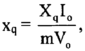
Un tel dispositif de commande décale le courant d'un angle α par rapport à la force électromotrice, tout en maintenant la tension constante, et la composante id de i dans l'axe direct d va créer un flux qui va s'opposer au flux principal. La force magnétomotrice totale se trouve donc réduite, entraînant par conséquent une chute de la tension induite globale.Such a control device shifts the current by an angle α relative to the electromotive force, while maintaining the constant voltage, and the component i d of i in the direct axis d will create a flow that will oppose the main flow. The total magnetomotive force is therefore reduced, thereby causing a drop in the overall induced voltage.
On ne peut augmenter la valeur unitaire i du courant au-delà de sa valeur nominale pour des raisons liées à l'échauffement de la machine et au calibre du dispositif de commande.The unit value i of the current can not be increased beyond its nominal value for reasons related to the heating of the machine and the caliber of the control device.
On peut obtenir la tension désirée avec le minimum de décalage α, c'est-à-dire la plus faible intensité directe unitaire id, afin de disposer de plus de courant en quadrature qui contribue à la création du couple.The desired voltage can be obtained with the minimum offset α, ie the lowest direct unit intensity i d , in order to have more current in quadrature which contributes to the creation of the couple.
Le rapport de défluxage est la valeur de m maximale qui permet d'obtenir la même puissance Po que celle qu'on obtient à la vitesse de base avec la même tension Vo et le même courant Io définis précédemment. On peut en déduire les valeurs de la force électromotrice, et celle des réactances directe et en quadrature pour une machine donnée. Le rapport Xd/Xq ainsi trouvé pour Po, Vo et Io donnés est une fonction croissante du rapport de défluxage recherché, ce dernier pouvant être par exemple supérieur à 2, étant par exemple égal à 6.The deflux ratio is the maximum value of m which makes it possible to obtain the same power P o as that obtained at the base speed with the same voltage V o and the same current I o defined previously. We can deduce the values of the electromotive force, and that of the direct and quadrature reactances for a given machine. The ratio X d / X q thus found for P o , V o and I o given is an increasing function of the desired defluxing ratio, the latter being for example greater than 2, being for example equal to 6.
Parmi les solutions (x, y) possibles, on choisit de préférence celle qui minimise i.Among the possible solutions (x, y), the one that minimizes i is preferably chosen.
Le dispositif de commande qui vient d'être décrit est de préférence utilisé en combinaison avec un moteur synchrone ayant Xd > Xq tel que défini plus haut.The control device which has just been described is preferably used in combination with a synchronous motor having X d > X q as defined above.
Le dispositif de commande peut comporter en outre :
- un onduleur triphasé,
- un contrôleur vectoriel agencé pour transmettre en fonction des intensités id et iq les signaux de commande aux interrupteurs électroniques de l'onduleur.
- a three-phase inverter,
- a vector controller arranged to transmit as a function of the intensities i d and i q the control signals to the electronic switches of the inverter.
L'invention a encore pour objet, indépendamment ou en combinaison avec ce qui précède, un procédé de contrôle d'un moteur dans lequel on mesure au moins la tension d'alimentation d'un onduleur relié au moteur et la vitesse de rotation du moteur, et on détermine par calcul en temps réel et/ou par accès à un registre les intensités directe id et en quadrature iq du courant d'alimentation permettant de maintenir, pour une consigne de vitesse Ω* donnée au dessus de la vitesse de base, la puissance constante.The invention further relates, independently or in combination with the foregoing, to a method of controlling an engine in which at least the supply voltage of an inverter connected to the motor and the speed of rotation of the motor are measured. and calculating in real time and / or access to a register the direct i d and quadrature i q currents of the supply current for maintaining, for a speed reference Ω * given above the speed of base, constant power.
On peut déterminer une consigne de couple t* en fonction au moins de l'écart entre la vitesse de rotation mesurée et la consigne de vitesse de rotation du rotor Ω*. On peut déterminer une consigne de puissance en fonction au moins de la consigne de couple et de la vitesse de rotation mesurée. On peut calculer les intensités unitaires directe id et en quadrature iq en temps réel à partir de la consigne de puissance, de la vitesse de rotation mesurée et de la tension continue d'alimentation de l'onduleur. Les intensités directe et en quadrature peuvent être déterminées selon les lois de commande en fonction de la charge et de la tension d'alimentation de l'onduleur. Ces lois de commande peuvent être intégrées dans le calculateur afin d'améliorer ses performances dynamiques.It is possible to determine a torque setpoint t * as a function of at least the difference between the measured rotational speed and the rotational speed reference of the rotor Ω *. A power setpoint can be determined as a function of at least the torque setpoint and the rotational speed measured. The direct unit intensities i d and in quadrature i q can be calculated in real time from the power setpoint, the rotational speed measured and the DC supply voltage of the inverter. The direct and quadrature currents can be determined according to the control laws as a function of the load and the supply voltage of the inverter. These control laws can be integrated into the computer to improve its dynamic performance.
La présente invention a encore pour objet, indépendamment ou en combinaison avec ce qui précède, un véhicule électrique comportant un moteur comportant :
- un stator, et
- au moins un rotor à aimants permanents,
où Xd est la réactance directe et Xq la réactance en quadrature.The present invention further relates, independently or in combination with the foregoing, to an electric vehicle comprising a motor comprising:
- a stator, and
- at least one rotor with permanent magnets,
where X d is the direct reactance and X q is the quadrature reactance.
Le véhicule peut encore comporter un dispositif de commande d'un moteur synchrone, permettant le fonctionnement du moteur à puissance constante sur une plage de vitesses de rotation du rotor, comportant un calculateur agencé pour déterminer les valeurs des intensités directe Id et en quadrature Iq du courant d'alimentation du moteur injectées dans le moteur, les intensités Id et Iq étant égales, à 20 % près, mieux à 10 % près, mieux encore à 5 % près, à : Id ≅ id-Io ≅ -i sin α.Io et Iq ≅ iq.Io ≅ i cos α.Io où Io est l'intensité maximale du courant imposée par le calibre du dispositif de commande, 
le courant unitaire circulant dans une phase de l'induit,
(x, y) étant l'une des racines réelles des équations 
m désigne le rapport entre la vitesse de rotation du rotor et la vitesse de base,
e est le rapport entre, d'une part, la force électromotrice, et d'autre part, le produit de m par la tension maximale par phase Vo imposée par le réseau d'alimentation,
v est le rapport entre la tension aux borne d'une phase de l'induit et la tension Vo imposée par le réseau d'alimentation,
p est le rapport entre la puissance effective et la puissance constante à laquelle on souhaite que la machine fonctionne, et
α le déphasage entre l'intensité et la force électromotrice.The vehicle may further comprise a control device of a synchronous motor, allowing operation of the constant power motor over a range of rotation speeds of the rotor, comprising a computer arranged to determine the values of the direct I d and quadrature I currents q of the supply current of the engine injected into the engine, the intensities I d and I q being equal, within 20%, better to within 10%, better still within 5%, to: I d ≅ i d -I o ≅ sin α.I -i o and q I q ≅ i .I o ≅ i cos α.I o where I o is the maximum current required by the control device of the caliber,
the unit current flowing in a phase of the armature,
(x, y) being one of the real roots of the equations
m denotes the ratio between the rotational speed of the rotor and the base speed,
e is the ratio between, on the one hand, the electromotive force, and, on the other hand, the product of m by the maximum voltage per phase V o imposed by the supply network,
v is the ratio between the voltage at the terminals of a phase of the armature and the voltage V o imposed by the supply network,
p is the ratio between the effective power and the constant power at which it is desired that the machine operate, and
α the phase difference between the intensity and the electromotive force.
La présente invention pourra être mieux comprise à la lecture de la description détaillée qui va suivre, d'un exemple non limitatif de mise en oeuvre de l'invention, et à l'examen du dessin annexé, sur lequel :
- la
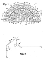
figure 1 représente de façon schématique et partielle, en coupe transversale, une machine conforme à l'invention, - la
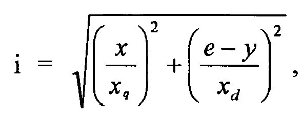
figure 2 est un diagramme de Blondel représentant différentes grandeurs sinusoïdales dans un repère lié à la pulsation électrique, - la
figure 3 est un schéma simplifié en blocs d'un dispositif de commande d'un moteur synchrone conforme à l'invention, et - la
figure 4 représente schématiquement un exemple de réalisation du calculateur principal du dispositif de commande de lafigure 3 .
- the
figure 1 represents schematically and partially, in cross-section, a machine according to the invention, - the
figure 2 is a Blondel diagram representing different sinusoidal quantities in a reference linked to the electric pulsation, - the
figure 3 is a simplified block diagram of a control device of a synchronous motor according to the invention, and - the
figure 4 schematically represents an embodiment of the main computer of the control device of thefigure 3 .
On a représenté sur la
Le stator 10 comporte des dents 11 portant chacune une bobine individuelle 12, les bobines 12 étant connectées électriquement entre elles de manière à être alimentées par un courant triphasé.The
Le rotor 20 est à concentration de flux, les aimants permanents 21 étant disposés entre des pièces polaires 22. Les aimants permanents 21 et les pièces polaires 22 sont fixés de façon appropriée sur un arbre 23 de la machine.The
Les pièces polaires 22 peuvent être maintenues sur l'arbre 23 par collage, ou encore par réalisation de formes complémentaires sur l'arbre et les pièces polaires, ou encore être maintenues par des barreaux engagés dans les pièces polaires 22 et fixés à leurs extrémités à des flasques du rotor.The
Les pièces polaires 22 sont réalisées par un empilage de tôles magnétiques recouvertes chacune d'un vernis isolant, afin de limiter les pertes par courants induits.The
Les aimants 21 ont des polarités de même nature, dirigées vers la pièce polaire 22 disposée entre eux, comme on peut le voir sur la
Les pièces polaires 22 comportent chacune une partie saillante 27, et leur face tournée vers le stator 10 présente une portion convexe 24. La portion convexe 24 d'une pièce polaire 22 peut présenter un rayon de courbure compris entre 20 % et 30 % d'un rayon du stator, notamment du rayon intérieur du stator, voire 25 % environ.The
Chaque portion convexe 24 comporte des extrémités circonférentielles 25 angulairement décalées par rapport aux aimants permanents 21 adjacents. Le décalage angulaire β des extrémités circonférentielles 25 par rapport aux aimants permanents 21 adjacents peut être compris :
- entre


entre 

par exemple de 

- enter
- enter
Dans ces relations, ndents désigne le nombre de dents 11 du stator et npôles le nombre de pièces polaires 27.In these relations, n teeth denotes the number of
Les aimants permanents 21 se situent radialement en retrait des extrémités circonférentielles 25 des portions convexes 24. Le retrait r dans la direction radiale des aimants 21 par rapport aux extrémités circonférentielles 25 des portions convexes 24 peut être compris entre 10 % et 20 %, voire de 15 % environ du rayon intérieur R du stator.The
Chaque pièce polaire 22 comporte en outre deux épaulements 26 situés de part et d'autre de la partie saillante 27, chaque aimant permanent 21 se situant entre deux épaulements 26.Each
Les parties saillantes 27 de chacune des pièces polaires 22 du rotor ont des bords radiaux 28 qui tout comme les extrémités circonférentielles 25 sont décalés angulairement par rapport aux faces 29, dirigées radialement, des aimants permanents 21 adjacents.The protruding
Les aimants permanents 21 présentent, lorsque la machine est observée selon l'axe de rotation X, une section transversale de forme allongée dans une direction radiale. Cette section transversale est, dans l'exemple décrit, rectangulaire, de grand côté orienté parallèlement à un rayon de la machine. En variante, les aimants permanents pourraient présenter chacun une forme de coin.The
Dans l'exemple considéré, le rotor comporte dix pôles et le stator douze dents, le stator comportant ainsi 6n dents et le rotor 6n ± 2 pôles, n étant égal à 2. On ne sort pas du cadre de la présente invention si n est supérieur à 2.In the example considered, the rotor comprises ten poles and the stator twelve teeth, the stator thus having 6n teeth and the rotor 6n ± 2 poles, n being equal to 2. It is not beyond the scope of the present invention if n is greater than 2.
Dans l'exemple décrit, le rotor est intérieur, mais on ne sort pas du cadre de la présente invention si le rotor est extérieur, ou si la machine comporte à la fois un rotor intérieur et un rotor extérieur, disposés chacun radialement de part et d'autre du stator et accouplés en rotation. Le moteur satisfait avantageusement, conformément à l'invention, à la relation Xd > Xq.In the example described, the rotor is internal, but it is not beyond the scope of the present invention if the rotor is external, or if the machine comprises both an inner rotor and an outer rotor, each arranged radially on each side. other of the stator and coupled in rotation. The motor advantageously satisfies, in accordance with the invention, the relation X d > X q .
La machine qui vient d'être décrite en référence à la
Pour plus de clarté, on a représenté sur la ![]()
![]()
Dans ce qui suit, on utilise les valeurs unitaires e, xd et xq définies plus haut.In what follows, we use the unit values e, x d and x q defined above.
Le décalage du courant unitaire i par rapport à la force électromotrice unitaire e est choisi pour maintenir la tension constante aux vitesses supérieures à la vitesse de base puisque la composante unitaire id de i dans l'axe direct d va créer un flux qui va s'opposer au flux principal, la force magnétomotrice totale se trouvant donc réduite et entraînant par conséquent une chute de la tension unitaire induite v, cela sans nuire outre mesure au couple moteur, le dispositif de commande étant agencé de manière à permettre à la machine de fonctionner avec le couple le plus grand possible au-delà de la vitesse de base. En particulier, le dispositif de commande vise à permettre de fonctionner avec une puissance au delà de la vitesse de base sensiblement égale à la puissance à la vitesse de base.The offset of the unit current i with respect to the unit electromotive force e is chosen to maintain the constant voltage at speeds higher than the base speed since the unit component i d of i in the direct axis d will create a flow that goes to oppose the main flow, the total magnetomotive force being thus reduced and consequently causing a fall in the induced unit voltage v, without unduly motor torque, the control device being arranged to allow the machine to operate with the greatest possible torque beyond the base speed. In particular, the control device aims to allow operation with a power beyond the base speed substantially equal to the power at the base speed.
Le moteur synchrone 1 est alimenté par un courant triphasé provenant d'un onduleur 35 comportant six interrupteurs électroniques 60, par exemple un ou plusieurs IGBT, associés chacun à une diode 61, et commandés par six signaux de commande 62 provenant d'un contrôleur vectoriel 37.The
Ce dernier permet de corriger l'intensité du courant fourni au moteur en fonction de consignes d'intensités directe id et en quadrature iq qu'il reçoit d'un calculateur principal 45, des intensités mesurées ia et ib pour deux des trois phases, et d'une information de position angulaire θ.The latter makes it possible to correct the intensity of the current supplied to the motor as a function of direct intensity orders i d and in quadrature i q that it receives from a
L'information de position angulaire θ est transmise par un calculateur de position 40 relié à un capteur de position 39.The angular position information θ is transmitted by a
Le capteur de position 39 est également relié à un calculateur de vitesse 41.The
La valeur de la vitesse de rotation Ω calculée par le calculateur de vitesse 41 est transmise au calculateur principal 45, à un multiplieur 46 et à un soustracteur 47.The value of the rotation speed Ω calculated by the
La vitesse de rotation Ω est soustraite à une consigne de vitesse de rotation du rotor Ω* dans le soustracteur 47, puis la différence Ω*-Ω est traitée par un circuit de régulation 48 de type PID (proportionnelle-intégrale-dérivée) et transmise à un calculateur de couple 49 qui détermine une consigne de couple t* en fonction de l'écart entre la vitesse de rotation mesurée Ω et la consigne de vitesse de rotation du rotor Ω*. La consigne de couple t* est plafonnée au couple maximum tmax que la machine est capable de fournir.The rotation speed Ω is subtracted from a rotation speed reference of the rotor Ω * in the
La consigne de couple t* est transmise au multiplieur 46 qui, en fonction de la vitesse de rotation mesurée Ω du rotor, calcule une consigne de puissance p*.The torque setpoint t * is transmitted to the
Cette consigne de puissance p* est transmise au calculateur principal 45.This power setpoint p * is transmitted to the
Par ailleurs, la tension VDC aux bornes de l'onduleur 35 est mesurée et transmise au calculateur principal 45 par un circuit de régulation 50 du type PID pour lisser les variations éventuelles. Ce circuit de régulation 50 fournit une tension unitaire v qui peut varier, étant dépendante de la tension du réseau.Furthermore, the voltage V DC across the
Le calculateur principal 45 détermine à partir des données qu'il reçoit les intensités directe id et en quadrature iq correspondant au fonctionnement à la puissance p*.The
Ces valeurs id et iq sont transmises au contrôleur vectoriel 37 et lui permettent de commander, comme cela a été décrit précédemment, l'onduleur 35.These values i d and i q are transmitted to the
Le calculateur principal 45 peut déterminer les valeurs id et iq par accès à un registre 53 contenant des valeurs précalculées, comme illustré à la
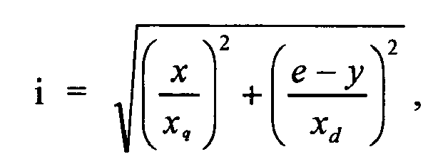
Le calculateur principal 45 peut encore déterminer id et iq analytiquement, par un calcul en temps réel, grâce aux formules suivantes : ![]()


(x, y) étant l'une des racines réelles des équations 
![]()
(x, y) being one of the real roots of the equations
Les termes « calculateur », « registre », « circuit de régulation », « soustracteur » et « multiplicateur » doivent être compris au sens large. Toutes ces fonctions peuvent être réalisées par un ou plusieurs circuits électroniques spécifiques logés sur une ou plusieurs cartes électroniques. Ces fonctions peuvent être réalisées sous forme matérielle et/ou logicielle. En particulier, les éléments 40, 41, 47, 48, 49, 46, 45, 50 et 37 peuvent être intégrés dans une même carte électronique comportant un ou plusieurs micro contrôleurs et/ou micro processeurs.The terms "calculator", "register", "regulating circuit", "subtractor" and "multiplier" must be understood in a broad sense. All these functions can be performed by one or more specific electronic circuits housed on one or more electronic cards. These functions can be realized in hardware and / or software. In particular, the
Dans l'exemple considéré, le rapport de défluxage est de 6, c'est-à-dire que la vitesse maximale de rotation du rotor est de six fois la vitesse de base, et par exemple de 1 350 tours par minute environ.In the example considered, the defluxing ratio is 6, that is to say that the maximum rotational speed of the rotor is six times the base speed, for example about 1350 revolutions per minute.
On ne sort bien entendu pas du cadre de la présente invention si le rapport de défluxage est différent de 6, notamment est supérieur ou égal à 2 par exemple. On dimensionne alors les interrupteurs électroniques 60 de l'onduleur 35 en conséquence.It is of course not departing from the scope of the present invention if the defluxing ratio is different from 6, in particular is greater than or equal to 2 for example. The
Bien entendu, l'invention n'est pas limitée à l'exemple de réalisation qui vient d'être décrit. Par exemple, on peut réaliser différemment la machine électrique tout en ayant Xd> Xq.Of course, the invention is not limited to the embodiment which has just been described. For example, the electric machine can be made differently while having X d > X q .
Dans toute la description, l'expression « comportant un » doit être considérée comme étant synonyme de « comportant au moins un », sauf si le contraire est spécifié.Throughout the description, the phrase "having one" should be considered synonymous with "having at least one", unless the opposite is specified.
Claims (15)
où Io est l'intensité maximale du courant imposée par le calibre du dispositif de commande,


le courant unitaire circulant dans une phase de
l'induit,
(x, y) étant l'une des racines réelles des équations

m désigne le rapport entre la vitesse de rotation du rotor et la vitesse de base,
e est le rapport entre, d'une part, la force électromotrice, et d'autre part, le produit de m par la tension Vo imposée par le réseau d'alimentation,
v est le rapport entre la tension aux borne d'une phase de l'induit et la tension maximale par phase Vo imposée par le réseau d'alimentation,
p est le rapport entre la puissance effective et la puissance Po,
α le déphasage entre l'intensité et la force électromotrice,
xd le quotient
xq le quotient

where I o is the maximum intensity of the current imposed by the size of the control device,
the unitary current circulating in a phase of
the armature,
(x, y) being one of the real roots of the equations
m denotes the ratio between the rotational speed of the rotor and the base speed,
e is the ratio between, on the one hand, the electromotive force, and, on the other hand, the product of m by the voltage V o imposed by the supply network,
v is the ratio between the voltage at the terminals of a phase of the armature and the maximum voltage per phase V o imposed by the supply network,
p is the ratio between the effective power and the power P o ,
α the phase difference between the intensity and the electromotive force,
x d the quotient
x q the quotient


Applications Claiming Priority (2)
| Application Number | Priority Date | Filing Date | Title |
|---|---|---|---|
| FR0303980A FR2853156A1 (en) | 2003-03-31 | 2003-03-31 | SYNCHRONOUS ELECTRIC MACHINE COMPRISING A STATOR AND AT LEAST ONE ROTOR AND CONTROL DEVICE THEREFOR |
| EP04742388A EP1609226B1 (en) | 2003-03-31 | 2004-03-29 | Synchronous electric motor comprising a stator and at least one rotor and associated control device |
Related Parent Applications (2)
| Application Number | Title | Priority Date | Filing Date |
|---|---|---|---|
| EP04742388.4 Division | 2004-03-29 | ||
| WOPCT/FR2004/000787 Previously-Filed-Application | 2004-03-29 |
Publications (1)
| Publication Number | Publication Date |
|---|---|
| EP2270956A2 true EP2270956A2 (en) | 2011-01-05 |
Family
ID=32947336
Family Applications (2)
| Application Number | Title | Priority Date | Filing Date |
|---|---|---|---|
| EP10177277A Withdrawn EP2270956A2 (en) | 2003-03-31 | 2004-03-29 | Synchronous electric machine comprising a stator and at least one rotor and associated control device. |
| EP04742388A Expired - Lifetime EP1609226B1 (en) | 2003-03-31 | 2004-03-29 | Synchronous electric motor comprising a stator and at least one rotor and associated control device |
Family Applications After (1)
| Application Number | Title | Priority Date | Filing Date |
|---|---|---|---|
| EP04742388A Expired - Lifetime EP1609226B1 (en) | 2003-03-31 | 2004-03-29 | Synchronous electric motor comprising a stator and at least one rotor and associated control device |
Country Status (7)
| Country | Link |
|---|---|
| US (1) | US7388310B2 (en) |
| EP (2) | EP2270956A2 (en) |
| JP (1) | JP4629659B2 (en) |
| CN (1) | CN1762084B (en) |
| ES (1) | ES2389841T3 (en) |
| FR (1) | FR2853156A1 (en) |
| WO (1) | WO2004091075A2 (en) |
Families Citing this family (24)
| Publication number | Priority date | Publication date | Assignee | Title |
|---|---|---|---|---|
| US7202625B2 (en) * | 2005-02-25 | 2007-04-10 | Caterpillar Inc | Multi-motor switched reluctance traction system |
| US7811068B2 (en) * | 2005-11-16 | 2010-10-12 | General Electric Company | Methods and apparatus for transporting natural gas through a pipeline |
| FR2895844A1 (en) * | 2006-01-03 | 2007-07-06 | Leroy Somer Moteurs | Radial or disk shaped rotating electrical machine, has pole piece associated with permanent magnets to concentrate magnetic flux of magnets, where magnets define three different magnetization directions |
| DE102006006824A1 (en) * | 2006-02-14 | 2007-08-23 | Siemens Ag | Permanent magnet synchronous machine and method and apparatus for its operation |
| US8018193B1 (en) | 2006-12-07 | 2011-09-13 | Purdue Research Foundation | Torque ripple mitigation controller with vibration sensor delay compensation |
| KR100915621B1 (en) * | 2007-03-29 | 2009-09-07 | 양성식 | Permanent Magnet Generator |
| CN102035277B (en) | 2009-10-07 | 2014-08-20 | 阿斯莫有限公司 | Motor |
| US9577503B2 (en) * | 2010-05-03 | 2017-02-21 | The Board Of Regents Of The University Of Texas System | Rotating machines using trapped field magnets and related methods |
| JP5888490B2 (en) * | 2011-11-10 | 2016-03-22 | 日本電産株式会社 | motor |
| KR20130092302A (en) * | 2012-02-10 | 2013-08-20 | 삼성전자주식회사 | Stator module and electric motor comprising the same |
| JP6002449B2 (en) * | 2012-05-31 | 2016-10-05 | 株式会社日立製作所 | Permanent magnet rotating electric machine, elevator hoisting machine |
| CN105179289B (en) * | 2012-05-31 | 2017-03-22 | 中山大洋电机股份有限公司 | Method for controlling variable-speed fan system |
| JP5898101B2 (en) * | 2013-01-16 | 2016-04-06 | 株式会社キトー | Electric motor for hoisting machine |
| JP2014180096A (en) * | 2013-03-14 | 2014-09-25 | Hitachi Industrial Equipment Systems Co Ltd | Permanent magnet dynamo-electric machine and elevator drive hoist |
| CN103219849A (en) * | 2013-05-06 | 2013-07-24 | 东南大学 | Rotor-permanent-magnetic type doubly-salient motor |
| FR3011145B1 (en) * | 2013-09-20 | 2017-04-14 | Valeo Equip Electr Moteur | DEVICE FOR DETERMINING AN ANGULAR POSITION AND / OR THE ROTATION SPEED OF A ROTOR OF A POLYPHASE ELECTRIC MOTOR AND CORRESPONDING ELECTRIC MOTOR |
| GB2522021B (en) * | 2014-01-08 | 2018-02-07 | Protean Electric Ltd | A rotor for an electric motor or generator |
| CN104467333B (en) * | 2014-12-01 | 2017-04-12 | 哈尔滨工业大学 | Rotor excitation multi-phase reluctance motor and control method thereof |
| CN205178812U (en) * | 2015-05-08 | 2016-04-20 | 德昌电机(深圳)有限公司 | Fan and single -phase external rotor brushless motor thereof |
| JP6536421B2 (en) * | 2016-02-02 | 2019-07-03 | 株式会社デンソー | Electric rotating machine |
| EP3454469B1 (en) * | 2017-09-12 | 2022-03-09 | Siemens Gamesa Renewable Energy A/S | Torque ripple reduction for a generator and wind turbine including the same |
| GB201717871D0 (en) | 2017-10-30 | 2017-12-13 | Romax Tech Limited | Motor |
| US11043879B2 (en) * | 2018-08-07 | 2021-06-22 | Tau Motors, Inc. | Electric motor with flux barriers |
| CN212323825U (en) * | 2020-01-07 | 2021-01-08 | 上海舞肌科技有限公司 | Permanent magnet brushless motor, robot joint, servo steering engine actuator and robot |
Family Cites Families (29)
| Publication number | Priority date | Publication date | Assignee | Title |
|---|---|---|---|---|
| US3979821A (en) * | 1975-05-09 | 1976-09-14 | Kollmorgen Corporation | Method of manufacturing rare earth permanent magnet rotor |
| US4339874A (en) * | 1978-12-26 | 1982-07-20 | The Garrett Corporation | Method of making a wedge-shaped permanent magnet rotor assembly |
| DE3016540A1 (en) * | 1980-04-29 | 1981-11-05 | Institut po Elektropromišlenost, Sofija | Rotary inductor for electrical machine - has permanent magnet rotors with magnets arranged radially with intermediate tapered pole pieces |
| JPS5859368U (en) * | 1981-10-15 | 1983-04-21 | 住友特殊金属株式会社 | Magnetic circuit for DC motor |
| JPS58151858A (en) * | 1982-03-04 | 1983-09-09 | Fanuc Ltd | Synchronous motor |
| US5015903A (en) * | 1988-08-15 | 1991-05-14 | Pacific Scientific Company | Electronically commutated reluctance motor |
| FR2655214B1 (en) * | 1989-11-27 | 1992-02-07 | Alsthom Gec | MAGNET MOTOR ROTOR. |
| FR2655784B1 (en) * | 1989-12-08 | 1992-01-24 | Alsthom Gec | FLOW CONCENTRATION MAGNET MOTOR. |
| CN2192975Y (en) * | 1994-06-07 | 1995-03-22 | 周伯飞 | Combined permanent-magnet motor rotor |
| JPH0870541A (en) * | 1994-08-30 | 1996-03-12 | Toshiba Corp | Permanent magnet-type rotating electric machine |
| FR2726948B1 (en) * | 1994-11-16 | 1996-12-20 | Wavre Nicolas | PERMANENT MAGNET SYNCHRONOUS MOTOR |
| TW380329B (en) * | 1997-04-16 | 2000-01-21 | Japan Servo | Permanent-magnet revolving electrodynamic machine with a concentrated winding stator |
| DE19723302A1 (en) * | 1997-06-04 | 1998-12-10 | Sen Rainer Born | Permanent magnet system with reluctance support for rotors of electrical machines |
| KR100263445B1 (en) * | 1997-11-13 | 2000-08-01 | 윤종용 | Rotor for brushless dc motor |
| JP3601757B2 (en) * | 1998-08-03 | 2004-12-15 | オークマ株式会社 | Permanent magnet motor |
| TW483216B (en) * | 1998-09-08 | 2002-04-11 | Toshiba Corp | Motor |
| JP2000156945A (en) * | 1998-11-18 | 2000-06-06 | Hitachi Ltd | Permanent magnet electric rotating machine and permanent magnet induction synchronous motor |
| JP2001211582A (en) * | 2000-01-26 | 2001-08-03 | Fujitsu General Ltd | Permanent magnet motor |
| JP2001292542A (en) * | 2000-04-05 | 2001-10-19 | Nissan Motor Co Ltd | Manufacturing method for stator core of motor and stator |
| JP3513467B2 (en) * | 2000-06-16 | 2004-03-31 | ファナック株式会社 | Synchronous motor rotor |
| JP2002112479A (en) * | 2000-09-27 | 2002-04-12 | Yaskawa Electric Corp | Permanent magnet motor and its control |
| FR2821024B1 (en) * | 2001-02-20 | 2003-06-13 | Leroy Somer Moteurs | DRIVE ELEMENT SUCH AS A DRIVE WHEEL OR A LIFTING WINCH COMPRISING A SYNCHRONOUS MOTOR |
| JP2002315243A (en) * | 2001-04-13 | 2002-10-25 | Hitachi Ltd | Permanent magnet type rotary electric machine |
| US6809654B2 (en) * | 2001-05-24 | 2004-10-26 | Ed Hudson | Message board with work lights for vehicles |
| JP2002354729A (en) * | 2001-05-25 | 2002-12-06 | Hitachi Ltd | Permanent magnet electric rotating machine and air conditioner using the same |
| US6700288B2 (en) * | 2001-08-15 | 2004-03-02 | Drs Power & Control Technologies, Inc. | High speed rotor |
| US6724114B2 (en) * | 2001-12-28 | 2004-04-20 | Emerson Electric Co. | Doubly salient machine with angled permanent magnets in stator teeth |
| US6727618B1 (en) * | 2002-06-10 | 2004-04-27 | The United States Of America, As Represented By The Administrator Of National Aeronautics And Space Administration | Bearingless switched reluctance motor |
| ITFI20030031A1 (en) | 2003-02-06 | 2004-08-07 | Univ Padova | PERMANENT MAGNET SYNCHRONOUS MOTOR WITH MODIFIED ROTOR |
-
2003
- 2003-03-31 FR FR0303980A patent/FR2853156A1/en not_active Withdrawn
-
2004
- 2004-03-29 JP JP2006505766A patent/JP4629659B2/en not_active Expired - Fee Related
- 2004-03-29 EP EP10177277A patent/EP2270956A2/en not_active Withdrawn
- 2004-03-29 CN CN200480007200.4A patent/CN1762084B/en not_active Expired - Fee Related
- 2004-03-29 US US10/547,194 patent/US7388310B2/en not_active Expired - Fee Related
- 2004-03-29 WO PCT/FR2004/000787 patent/WO2004091075A2/en active Application Filing
- 2004-03-29 EP EP04742388A patent/EP1609226B1/en not_active Expired - Lifetime
- 2004-03-29 ES ES04742388T patent/ES2389841T3/en not_active Expired - Lifetime
Non-Patent Citations (1)
| Title |
|---|
| None |
Also Published As
| Publication number | Publication date |
|---|---|
| EP1609226A2 (en) | 2005-12-28 |
| WO2004091075A3 (en) | 2005-06-09 |
| ES2389841T3 (en) | 2012-11-02 |
| EP1609226B1 (en) | 2012-06-20 |
| US20060097594A1 (en) | 2006-05-11 |
| CN1762084B (en) | 2010-05-05 |
| CN1762084A (en) | 2006-04-19 |
| JP4629659B2 (en) | 2011-02-09 |
| US7388310B2 (en) | 2008-06-17 |
| FR2853156A1 (en) | 2004-10-01 |
| JP2006522578A (en) | 2006-09-28 |
| WO2004091075A2 (en) | 2004-10-21 |
Similar Documents
| Publication | Publication Date | Title |
|---|---|---|
| EP1609226B1 (en) | Synchronous electric motor comprising a stator and at least one rotor and associated control device | |
| BE1004032A3 (en) | Engine multi bipolar dc brushless. | |
| EP1632019B1 (en) | Pulse width modulation control circuit for multi-mode electrical machine and multimode electrical machine provided with such a control circuit | |
| EP0289075B1 (en) | Reluctance electric machine | |
| EP2142397B1 (en) | Device and method for controlling a power shunt circuit, hybrid vehicle having same | |
| EP2400636A1 (en) | Alternating-current electric motor being able to be connected into the charging circuit for batteries | |
| EP0783201B1 (en) | Synchronous type electric motor and vehicle equipped with such a motor | |
| WO2013079842A2 (en) | Rotor for a rotary electric machine and rotary electric machine comprising such a rotor | |
| FR2999039A1 (en) | METHOD AND CONTROL INSTALLATION FOR DETERMINING THE ROTATION ANGLE OF A SYNCHRONOUS MACHINE | |
| Nguyen et al. | Permanent magnet synchronous machines: Performances during driving cycles for a hybrid electric vehicle application | |
| EP3053262A2 (en) | Multiphase electric rotating machine with at least five phases | |
| WO2011018716A2 (en) | Rotating electric machine comprising an exciter | |
| FR2714773A1 (en) | Electronically switched permanent magnet synchronous motor for motor vehicle electric power assisted steering system | |
| EP2537702B1 (en) | Configuration of a stator of a rotating electric machine | |
| EP2777139B1 (en) | Control method for a double-excitation synchronous electrical rotating machine and corresponding rotating machine | |
| EP2777135B1 (en) | Rotor for a rotary electric machine, and rotary electric machine including such a rotor | |
| EP2866344A2 (en) | Polyphase rotary electrical machine having at least five phases with optimised control | |
| EP2870684B1 (en) | Rotating electric machine with compensation of armature magnetic feedback | |
| EP2751914B1 (en) | Rotary electric machine | |
| EP2416490B1 (en) | Power train for a transport vehicle, in particular a railway vehicle, and method for controlling such a chain | |
| FR2744301A1 (en) | INVERTER FOR SUPPLYING AN ELECTRIC VEHICLE TRACTION MOTOR | |
| Ying et al. | Application for Step-skewing of Rotor of IPM Motors Used in EV | |
| EP2302768A1 (en) | Device for supplying direct current to a rotor coil of a synchronous electric rotating machine and drive system comprising such a supply device | |
| BE529665A (en) | ||
| WO2016120533A1 (en) | Reduction of the vibratory and acoustic nuisances of an asynchronous machine |
Legal Events
| Date | Code | Title | Description |
|---|---|---|---|
| PUAI | Public reference made under article 153(3) epc to a published international application that has entered the european phase |
Free format text: ORIGINAL CODE: 0009012 |
|
| 17P | Request for examination filed |
Effective date: 20100917 |
|
| AC | Divisional application: reference to earlier application |
Ref document number: 1609226 Country of ref document: EP Kind code of ref document: P |
|
| AK | Designated contracting states |
Kind code of ref document: A2 Designated state(s): AT BE BG CH CY CZ DE DK EE ES FI FR GB GR HU IE IT LI LU MC NL PL PT RO SE SI SK TR |
|
| RIN1 | Information on inventor provided before grant (corrected) |
Inventor name: SAINT MICHEL, JACQUES Inventor name: ABOU AKAR, ATEF |
|
| STAA | Information on the status of an ep patent application or granted ep patent |
Free format text: STATUS: THE APPLICATION IS DEEMED TO BE WITHDRAWN |
|
| 18D | Application deemed to be withdrawn |
Effective date: 20121002 |