EP2269474A2 - Method and apparatus for ultrasonic freezing - Google Patents
Method and apparatus for ultrasonic freezing Download PDFInfo
- Publication number
- EP2269474A2 EP2269474A2 EP10006592A EP10006592A EP2269474A2 EP 2269474 A2 EP2269474 A2 EP 2269474A2 EP 10006592 A EP10006592 A EP 10006592A EP 10006592 A EP10006592 A EP 10006592A EP 2269474 A2 EP2269474 A2 EP 2269474A2
- Authority
- EP
- European Patent Office
- Prior art keywords
- product
- cryogenic substance
- container
- ultrasonic transducer
- transducer assembly
- Prior art date
- Legal status (The legal status is an assumption and is not a legal conclusion. Google has not performed a legal analysis and makes no representation as to the accuracy of the status listed.)
- Withdrawn
Links
- 238000000034 method Methods 0.000 title claims description 8
- 238000007710 freezing Methods 0.000 title description 11
- 230000008014 freezing Effects 0.000 title description 11
- IJGRMHOSHXDMSA-UHFFFAOYSA-N Atomic nitrogen Chemical compound N#N IJGRMHOSHXDMSA-UHFFFAOYSA-N 0.000 claims abstract description 41
- CURLTUGMZLYLDI-UHFFFAOYSA-N Carbon dioxide Chemical compound O=C=O CURLTUGMZLYLDI-UHFFFAOYSA-N 0.000 claims abstract description 12
- 229910002092 carbon dioxide Inorganic materials 0.000 claims abstract description 7
- 239000001569 carbon dioxide Substances 0.000 claims abstract description 7
- JCXJVPUVTGWSNB-UHFFFAOYSA-N nitrogen dioxide Inorganic materials O=[N]=O JCXJVPUVTGWSNB-UHFFFAOYSA-N 0.000 claims abstract description 4
- 239000000126 substance Substances 0.000 claims description 17
- 230000006911 nucleation Effects 0.000 claims description 12
- 238000010899 nucleation Methods 0.000 claims description 12
- 235000013305 food Nutrition 0.000 claims description 9
- 238000007654 immersion Methods 0.000 claims description 8
- 230000005540 biological transmission Effects 0.000 claims description 3
- 230000004888 barrier function Effects 0.000 claims 2
- 238000005507 spraying Methods 0.000 claims 1
- 239000012530 fluid Substances 0.000 abstract description 7
- 239000007788 liquid Substances 0.000 description 20
- 229910052757 nitrogen Inorganic materials 0.000 description 16
- 239000007921 spray Substances 0.000 description 14
- 230000000694 effects Effects 0.000 description 4
- 239000007789 gas Substances 0.000 description 4
- 238000010276 construction Methods 0.000 description 3
- 241000287828 Gallus gallus Species 0.000 description 2
- 230000015572 biosynthetic process Effects 0.000 description 2
- 229910001873 dinitrogen Inorganic materials 0.000 description 2
- 238000012986 modification Methods 0.000 description 2
- 230000004048 modification Effects 0.000 description 2
- 239000000956 alloy Substances 0.000 description 1
- 229910045601 alloy Inorganic materials 0.000 description 1
- 238000000889 atomisation Methods 0.000 description 1
- 238000010923 batch production Methods 0.000 description 1
- 238000010924 continuous production Methods 0.000 description 1
- 238000001816 cooling Methods 0.000 description 1
- 230000001419 dependent effect Effects 0.000 description 1
- 238000002194 freeze distillation Methods 0.000 description 1
- 239000007792 gaseous phase Substances 0.000 description 1
- 239000007791 liquid phase Substances 0.000 description 1
- 239000002184 metal Substances 0.000 description 1
- 238000010791 quenching Methods 0.000 description 1
- 230000000171 quenching effect Effects 0.000 description 1
- 239000007787 solid Substances 0.000 description 1
- 238000002604 ultrasonography Methods 0.000 description 1
Images


Classifications
-
- A—HUMAN NECESSITIES
- A23—FOODS OR FOODSTUFFS; TREATMENT THEREOF, NOT COVERED BY OTHER CLASSES
- A23B—PRESERVATION OF FOODS, FOODSTUFFS OR NON-ALCOHOLIC BEVERAGES; CHEMICAL RIPENING OF FRUIT OR VEGETABLES
- A23B2/00—Preservation of foods or foodstuffs, in general
- A23B2/80—Freezing; Subsequent thawing; Cooling
- A23B2/85—Freezing; Subsequent thawing; Cooling with addition of or treatment with chemicals
- A23B2/88—Freezing; Subsequent thawing; Cooling with addition of or treatment with chemicals with direct contact between the food and the chemical, e.g. liquid N2 at cryogenic temperature
-
- A—HUMAN NECESSITIES
- A23—FOODS OR FOODSTUFFS; TREATMENT THEREOF, NOT COVERED BY OTHER CLASSES
- A23B—PRESERVATION OF FOODS, FOODSTUFFS OR NON-ALCOHOLIC BEVERAGES; CHEMICAL RIPENING OF FRUIT OR VEGETABLES
- A23B2/00—Preservation of foods or foodstuffs, in general
- A23B2/50—Preservation of foods or foodstuffs, in general by irradiation without heating
- A23B2/57—Preservation of foods or foodstuffs, in general by irradiation without heating by treatment with ultrasonic waves
-
- F—MECHANICAL ENGINEERING; LIGHTING; HEATING; WEAPONS; BLASTING
- F25—REFRIGERATION OR COOLING; COMBINED HEATING AND REFRIGERATION SYSTEMS; HEAT PUMP SYSTEMS; MANUFACTURE OR STORAGE OF ICE; LIQUEFACTION SOLIDIFICATION OF GASES
- F25D—REFRIGERATORS; COLD ROOMS; ICE-BOXES; COOLING OR FREEZING APPARATUS NOT OTHERWISE PROVIDED FOR
- F25D3/00—Devices using other cold materials; Devices using cold-storage bodies
- F25D3/10—Devices using other cold materials; Devices using cold-storage bodies using liquefied gases, e.g. liquid air
- F25D3/11—Devices using other cold materials; Devices using cold-storage bodies using liquefied gases, e.g. liquid air with conveyors carrying articles to be cooled through the cooling space
-
- F—MECHANICAL ENGINEERING; LIGHTING; HEATING; WEAPONS; BLASTING
- F25—REFRIGERATION OR COOLING; COMBINED HEATING AND REFRIGERATION SYSTEMS; HEAT PUMP SYSTEMS; MANUFACTURE OR STORAGE OF ICE; LIQUEFACTION SOLIDIFICATION OF GASES
- F25D—REFRIGERATORS; COLD ROOMS; ICE-BOXES; COOLING OR FREEZING APPARATUS NOT OTHERWISE PROVIDED FOR
- F25D2400/00—General features of, or devices for refrigerators, cold rooms, ice-boxes, or for cooling or freezing apparatus not covered by any other subclass
- F25D2400/30—Quick freezing
Definitions
- the embodiments relate to freezing of products, such as for example food products, in immersion and convection freezing systems.
- the embodiments of the invention relate to an apparatus for reducing a temperature of a product, comprising a container; a cryogenic substance provided to the container to reduce a temperature of at least a surface of the product; an ultrasonic transducer assembly disposed at the container in spaced relation from the product, the ultrasonic transducer assembly providing ultrasonic energy to the cryogenic substance to induce cavitation for destroying nucleation at the surface of the product during exposure to the cryogenic substance.
- the embodiments of the invention further relate to a method of reducing a temperature of a product, comprising exposing a surface of the product to a cryogenic substance for heat transfer at said surface; providing ultrasonic energy to the cryogenic substance and the product to induce cavitation for destroying nucleation at the surface of the product.
- the invention relates to an apparatus for reducing a temperature of a product, comprising a housing in which cryogenic fluid is provided for being exposed to the product and at least one ultrasonic transducer assembly disposed in the housing for generating ultrasonic energy to contact the cryogenic fluid and a surface of the product to facilitate heat transfer at the surface of the product.
- the cryogenic fluid preferably comprises a liquid bath, nitrogen, a fog and/or a fog comprising nitrogen.
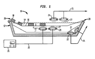
- FIG. 1 is a side view of one embodiment of the invention
- FIG. 2 is a side view of another embodiment of the invention.
- FIG. 3 is a view of a portion of an alternative embodiment from that shown in FIG. 2 .
- FIGS. 1-3 show ultrasonic immersion and convection tunnel freezing system embodiments to prepare and treat products, such as food products for example, for subsequent processing.
- the freezer 10 may be constructed as a container which includes an insulated sidewall 12 in which a bath 14 of liquid nitrogen (N 2 ) is disposed and contained.
- a conveyor belt 16 extends through the bath 14 to deliver products 18, such as for example food products, through the bath 14.
- the sidewall 12 may be extended to form the container as a housing covering the bath 14, and provide an inlet and outlet for the belt 16 at the housing.
- the conveyor belt 16 is constructed and arranged to accommodate different types and sizes of the product 18 to be immersed into the bath 14.
- the conveyor belt 16 can be adjusted such that all of the product 18 is immersed in the bath 14, or only a select portion of the product 18 is immersed in the bath 14. Residence time of the product 18 in the bath 14 will be determined by the particular product to be frozen.
- Such construction for the conveyor belt 16 may be of wire mesh or slat-like longitudinal members having spaces therebetween for the cryogenic bath to more readily access and contact the product 18.
- Ultrasonic transducers arranged singly, in pairs or in any other numerical combinations and arrangements, are disposed with respect to the system 10.
- a transducer 20 may be disposed in the liquid nitrogen bath 14 either alone, or as a pair or any number of transducers 20. Depending upon the volume and the dimensions of the housing 12 for the bath 14, there may be a plurality of pairs of the transducers 20.
- transducers 22 may be mounted singly or as a pair or any number of transducers 22 at an inner sidewall of the housing 12 for exposure as well to the nitrogen bath 14.
- a transducer 24 may be disposed above the nitrogen bath 14 either singly or as a pair of transducers 24. With respect to the transducers 20-24, any number of ultrasonic transducers may be employed depending upon the particular freezing application, the size and depth of the liquid nitrogen bath 14, and the physical characteristics of the product 18 being processed.
- the transducers 20-24 are connected, as shown generally at 25, to an ultrasonic generator 26, which in turn is connected to and can be controlled by a controller device (not shown).
- the system 10 is provided with an inlet 26 and an outlet 28 for the conveyor belt 16, and hence the product 18 for introduction into and out of the bath 14.
- the product 18 such as for example a food product
- the product 18 is loaded on the conveyor belt 16 and introduced by the conveyor belt 16 in a batch or continuous process into the liquid nitrogen bath 14.
- heat transfer occurs and boil off is immediate.
- nucleation which is the formation of extremely small nitrogen gas bubbles at the surface of the product 18 exposed to the liquid nitrogen in the bath 14.
- the bubbles rapidly increase in number, they provide a shielding effect and create a boundary layer at a surface of the product 18, in effect insulating or encapsulating the product in a multiplicity of nitrogen gas bubbles which substantially reduces heat transfer effectiveness at the surface of the product 18.
- one or more of the ultrasonic transducers 20-24 are actuated, such that sound waves 27 provide cavitation to counteract the nucleation, i.e. the cavitation destroys the bubbles and boundary layer created by the nucleation to thereby prevent the formation of an insulatory bubble or gas layer at the surface of the product 18 so that heat transfer at the surface is not reduced by the nucleation.
- the efficiency and effectiveness of this process is further realized by the product being directly exposed and in contact with the liquid nitrogen bath 14 and the ultrasonic waves 27 throughout the process while the waves are in contact the with product 18.
- the product 18 is directly exposed to the liquid nitrogen in the bath 14 so that the cavitation with respect to the nucleation is complete and total.
- Heat transfer is also increased by way of microstreaming which means that as gas bubbles at the surface of the product are rapidly destroyed by ultrasonic energy, pulses of high pressure gas are released which increase surface heat transfer.
- the transducers 20-24 can be arranged in the liquid nitrogen bath 14 or in the atmosphere above the bath 14, such as is shown with the transducers 24.
- the effectiveness of the ultrasonic energy to provide cavitation and destroy nucleation is increased the closer the transducers 20-24 are to the liquid nitrogen and the product 18. That is, the transducers 20 are more effective than the transducers 22, which in turn are more effective than the transducers 24.
- a distance d1 of 30 mm is provided between the product 18 and a transmitting surface of the transducers 20-24.
- a convection tunnel embodiment is shown generally at 40 having ultrasonic transducers.
- the embodiment includes a housing 42.
- the housing includes a top 43, sidewalls 45 and a bottom 47, which define a chamber 44 disposed therein.
- a conveyor belt 46 extends from an inlet 48 to an outlet 50 of the housing 42.
- the housing 42 may be insulated.
- Product 52 such as food product, is transported along the conveyor belt 46 between the inlet 48 to the outlet 50 of the housing 42.
- Cryogenic liquid such as nitrogen (N 2 ) or carbon dioxide (CO 2 )
- N 2 nitrogen
- CO 2 carbon dioxide
- the cryogenic liquid nitrogen or carbon dioxide is transported through the conduit 54 into the manifold 56 for being distributed in gaseous or liquid phase jets 59 from the spray nozzles 58 into the chamber 44.
- Fans 60, impellers, blowers or a combination of such, in the chamber 44 are connected to corresponding motors 62 for circulating the cryogen liquid in the chamber 44.
- an impingement plate 64 Disposed between the manifold 56 and the conveyor belt 46 is an impingement plate 64 having a plurality of a jet nozzle apertures 65 arranged therein.
- the impingement plate 64 may be arranged to extend across an entire length of the chamber 44, thereby segregating a portion of the chamber from the conveyor belt 46.
- Ultrasonic transducers 68 are arranged in the chamber 44 proximate the impingement plate 64.
- the ultrasonic transducers 68 provide ultrasonic energy proximate the impingement plate 64.
- the cryogenic liquid spray 66 being sprayed by the impingement jet nozzles 65 is directed toward the product 52.
- the ultrasonic energy will atomize the liquid cryogen spray 66 into a fog, for example a nitrogen fog.
- CO 2 will be injected in a solid state, for increased heat transfer at the product 52 surface. Similar to the embodiment of FIG. 1 , the ultrasonic energy destroys any nucleation of the cryogenic bubbles that may form at the surface of the product 52. The microstreaming effect will also occur at this stage with this embodiment.
- FIG. 2 Other embodiments of the system embodiment 40 of FIG. 2 include arranging ultrasonic transducers 72 beneath the conveyor belt 46 or alternatively arranging ultrasonic transducers 74 proximate a side of the conveyor belt 46. It should be understood that use of the transducer 68, 72, 74 is not limited to one of each, but rather the transducers 68, 72, 74 may be arranged singly, in pairs or in any combination arranged within the housing 42.
- the product 52 or products are loaded onto the conveyor belt 46 and transferred from the inlet 48 into the housing 42 of the system 40 for treatment at the chamber 44 prior to being removed at the outlet 50.
- the fans 60 circulate the cryogenic jet spray 59 emitted from the spray nozzles 58 for circulation in the chamber 44.
- the jet spray 59 from the spray nozzles 58 is forced toward the impingement plate 64 and accordingly through the impingement nozzle 65 or nozzles to provide the spray 66 of the cryogenic substance to contact a surface of the product 52.
- the transducers 68, 72, 74 are actuated to provide ultrasonic waves 71 to the cryogen spray 66 to provide a cryogenic fog (when nitrogen is used) from the spray at the surface of the product 52.
- the ultrasonic wave 71 energy will also destroy the boundary layer of any gas that surrounds the product 52 surface and which inhibits freezing of the product. This causes a high heat transfer effect, as it does with the embodiment of FIG. 1 , to provide for a rapid crusting of the surface of the product 52 for subsequent treatment or processing.
- the transducers 68, 72, 74 are at a select distance from the product 52, which by way of example only, is a distance d2 of not more than 30 mm.
- the distance d2 can be selected depending upon the type and amount of the product 52 being crust frozen, the residence time of the product 52 when being subjected to the cryogen, and the size and number of the transducers 68, 72, 74 being employed in the housing.
- FIG. 3 shows an alternate embodiment of that which is shown in FIG. 2 with respect to the disposition of ultrasonic transducers for the freezing operation.
- the conduit 54 is connected to the manifold 56 from which the nozzles 58 provide the spray 59 of the cryogen fluid, such as either liquid nitrogen or carbon dioxide, into the chamber 44.
- the conveyor belt 46 extends and travels through the chamber 44 for transporting the product 52 through the chamber for the freezing operation.
- the conveyor belt 46 shown in FIG. 3 may be of construction similar to the conveyor belt shown in FIG. 2 and the conveyor belt 16 of FIG. 1 .
- Such construction for the conveyor belt 46 may be of wire mesh or slat-like longitudinal members having spaces therebetween for the cryogenic liquid spray to access and contact the product 52.
- the impingement plate 64 with the impingement jet nozzle apertures 66 are constructed and arranged to accommodate the ultrasonic transducers 68.
- the transducers 68 are arranged above the conveyor belt 46 parallel or alternatively aligned with the impingement plate 64.
- a distance d3 between a transmission surface 69 of the transducer 68 to the product 52 is 30 mm by way of example only.
- the transducer 72 or transducers may also be disposed beneath the conveyor belt 46 to provide ultrasonic energy from below the product 52.
- Another impingement plate 76 with impingement jet apertures 78 can be arranged beneath the conveyor belt 46, with the transducers 72 arranged in parallel or alternatively aligned with the impingement plate 76.
- Sound waves 80 generated from the transducers 68, 72 are therefore able to be directed toward a lower surface as well of the product 52.
- the distance d3 would also be selected, measured from the transmission surface of the transducer 72 to the product 52.
- FIG. 2 the embodiment of FIG.
- the products 18, 52 may be for example metal parts and components, or food products such as for example food items as large as chicken patties and chicken cutlets.
- the freezer apparatus may be a liquid cryogen immersion bath, a freezing tunnel, a fluidized bed or any combination thereof.
- the embodiments also provide for an "in-line (post-cooling) process", wherein for example the inlet 48 of the convection tunnel is connected to the outlet 28 of the immersion freezer 10 and the respective embodiments are fabricated as modules.
- the embodiments described above may also be used on the products 18, 52 that are metallic or alloy products that require quenching.
- the sound waves 80 may actually contact the product 52.
- the embodiments may also be provided with a closed-loop cryogen delivery system having control valves to enable to continuous or pulse jets of cryogen flow to the chamber 44, wherein a portion of the evaporated/sublimed cryogen can be recycled as additional intake for cryogen impingement.
- power for the ultrasound produced by the transducers 20-24, 68, 72, 74 may have a frequency of approximately 20-200 kiloHertz (kHz), such as for example 20-30 kHz.
- the power intensity of the transducers is also tunable, such as for example tuning to the range of 1-50 kW/m2.
- the direction of the ultrasonic field emitted from the transducers 20-24 and 68, 72, 74 and sensors to trigger the transducers upon entry of the product 18, 52 into the bath 14 or chamber 44, respectively, can be adjusted depending upon particulars of the products 18, 52 to be treated.
- Exposure time for the products to one pulse of ultrasonic energy would be approximately a minimum of 0.5 second, while the interval between ultrasonic energy pulses would be adjusted according to the speed of advance of the conveyor belt 16, 46.
- the ultrasonic transducers 20-24 and 68, 72, 74 may be magnetostrictive or piezoelectric. In certain freezing applications, it may be necessary to precool the product 18, 52 to a temperature of approximately 1-5°C lower than the products freezing point. In a precooling application, the product 18, 52 could be subcooled to below its normal freezing point, then ultrasonic energy could be used to induce a rapid freeze throughout the product.
Landscapes
- Engineering & Computer Science (AREA)
- Life Sciences & Earth Sciences (AREA)
- Chemical & Material Sciences (AREA)
- Polymers & Plastics (AREA)
- Zoology (AREA)
- Food Science & Technology (AREA)
- Wood Science & Technology (AREA)
- Combustion & Propulsion (AREA)
- Physics & Mathematics (AREA)
- Mechanical Engineering (AREA)
- Thermal Sciences (AREA)
- General Engineering & Computer Science (AREA)
- Freezing, Cooling And Drying Of Foods (AREA)
- Physical Or Chemical Processes And Apparatus (AREA)
Abstract
Description
- The embodiments relate to freezing of products, such as for example food products, in immersion and convection freezing systems.
- The embodiments of the invention relate to an apparatus for reducing a temperature of a product, comprising a container; a cryogenic substance provided to the container to reduce a temperature of at least a surface of the product; an ultrasonic transducer assembly disposed at the container in spaced relation from the product, the ultrasonic transducer assembly providing ultrasonic energy to the cryogenic substance to induce cavitation for destroying nucleation at the surface of the product during exposure to the cryogenic substance.
- The embodiments of the invention further relate to a method of reducing a temperature of a product, comprising exposing a surface of the product to a cryogenic substance for heat transfer at said surface; providing ultrasonic energy to the cryogenic substance and the product to induce cavitation for destroying nucleation at the surface of the product.
- Preferred embodiments of the invention are disclosed in the dependent claims.
- According to another embodiment the invention relates to an apparatus for reducing a temperature of a product, comprising a housing in which cryogenic fluid is provided for being exposed to the product and at least one ultrasonic transducer assembly disposed in the housing for generating ultrasonic energy to contact the cryogenic fluid and a surface of the product to facilitate heat transfer at the surface of the product.
- The cryogenic fluid preferably comprises a liquid bath, nitrogen, a fog and/or a fog comprising nitrogen.
- For a more complete understanding of the present embodiments, reference may be had to the detailed description which follows taken in conjunction with the drawings, of which:
-
FIG. 1 is a side view of one embodiment of the invention; -
FIG. 2 is a side view of another embodiment of the invention; and -
FIG. 3 is a view of a portion of an alternative embodiment from that shown inFIG. 2 . -
FIGS. 1-3 show ultrasonic immersion and convection tunnel freezing system embodiments to prepare and treat products, such as food products for example, for subsequent processing. - Referring to
FIG. 1 , an immersion freezer embodiment is shown generally at 10. Thefreezer 10 may be constructed as a container which includes aninsulated sidewall 12 in which abath 14 of liquid nitrogen (N2) is disposed and contained. Aconveyor belt 16 extends through thebath 14 to deliverproducts 18, such as for example food products, through thebath 14. (As shown inFIG. 2 , thesidewall 12 may be extended to form the container as a housing covering thebath 14, and provide an inlet and outlet for thebelt 16 at the housing.) Theconveyor belt 16 is constructed and arranged to accommodate different types and sizes of theproduct 18 to be immersed into thebath 14. That is, depending upon theproduct 18, regardless of whether it is a food product or otherwise, theconveyor belt 16 can be adjusted such that all of theproduct 18 is immersed in thebath 14, or only a select portion of theproduct 18 is immersed in thebath 14. Residence time of theproduct 18 in thebath 14 will be determined by the particular product to be frozen. Such construction for theconveyor belt 16 may be of wire mesh or slat-like longitudinal members having spaces therebetween for the cryogenic bath to more readily access and contact theproduct 18. - Ultrasonic transducers arranged singly, in pairs or in any other numerical combinations and arrangements, are disposed with respect to the
system 10. A transducer 20 may be disposed in theliquid nitrogen bath 14 either alone, or as a pair or any number of transducers 20. Depending upon the volume and the dimensions of thehousing 12 for thebath 14, there may be a plurality of pairs of the transducers 20. Similarly,transducers 22 may be mounted singly or as a pair or any number oftransducers 22 at an inner sidewall of thehousing 12 for exposure as well to thenitrogen bath 14. Atransducer 24 may be disposed above thenitrogen bath 14 either singly or as a pair oftransducers 24. With respect to the transducers 20-24, any number of ultrasonic transducers may be employed depending upon the particular freezing application, the size and depth of theliquid nitrogen bath 14, and the physical characteristics of theproduct 18 being processed. - The transducers 20-24 are connected, as shown generally at 25, to an
ultrasonic generator 26, which in turn is connected to and can be controlled by a controller device (not shown). Thesystem 10 is provided with aninlet 26 and anoutlet 28 for theconveyor belt 16, and hence theproduct 18 for introduction into and out of thebath 14. - In operation, the
product 18 such as for example a food product, is loaded on theconveyor belt 16 and introduced by theconveyor belt 16 in a batch or continuous process into theliquid nitrogen bath 14. Upon contact of theproduct 18 with theliquid nitrogen bath 14, heat transfer occurs and boil off is immediate. Such heat transfer of theproduct 18 and boil off in thebath 14 causes nucleation, which is the formation of extremely small nitrogen gas bubbles at the surface of theproduct 18 exposed to the liquid nitrogen in thebath 14. As the bubbles rapidly increase in number, they provide a shielding effect and create a boundary layer at a surface of theproduct 18, in effect insulating or encapsulating the product in a multiplicity of nitrogen gas bubbles which substantially reduces heat transfer effectiveness at the surface of theproduct 18. - Accordingly, prior to or upon entry of the
product 18 into thebath 14 one or more of the ultrasonic transducers 20-24 are actuated, such thatsound waves 27 provide cavitation to counteract the nucleation, i.e. the cavitation destroys the bubbles and boundary layer created by the nucleation to thereby prevent the formation of an insulatory bubble or gas layer at the surface of theproduct 18 so that heat transfer at the surface is not reduced by the nucleation. The efficiency and effectiveness of this process is further realized by the product being directly exposed and in contact with theliquid nitrogen bath 14 and theultrasonic waves 27 throughout the process while the waves are in contact the withproduct 18. In other words, in the present embodiment theproduct 18 is directly exposed to the liquid nitrogen in thebath 14 so that the cavitation with respect to the nucleation is complete and total. Heat transfer is also increased by way of microstreaming which means that as gas bubbles at the surface of the product are rapidly destroyed by ultrasonic energy, pulses of high pressure gas are released which increase surface heat transfer. - As shown in
FIG. 1 , the transducers 20-24 can be arranged in theliquid nitrogen bath 14 or in the atmosphere above thebath 14, such as is shown with thetransducers 24. The effectiveness of the ultrasonic energy to provide cavitation and destroy nucleation is increased the closer the transducers 20-24 are to the liquid nitrogen and theproduct 18. That is, the transducers 20 are more effective than thetransducers 22, which in turn are more effective than thetransducers 24. The further away the ultrasonic transducers 20-24 are from theproduct 18, the more energy is required to provide the sonic energy to theproduct 18, which of course translates into a higher cost to operate the system. In addition, and by way of example only, a distance d1 of 30 mm is provided between theproduct 18 and a transmitting surface of the transducers 20-24. - Referring to
FIG. 2 , a convection tunnel embodiment is shown generally at 40 having ultrasonic transducers. The embodiment includes ahousing 42. The housing includes atop 43,sidewalls 45 and abottom 47, which define achamber 44 disposed therein. Aconveyor belt 46 extends from aninlet 48 to anoutlet 50 of thehousing 42. Thehousing 42 may be insulated. -
Product 52, such as food product, is transported along theconveyor belt 46 between theinlet 48 to theoutlet 50 of thehousing 42. Cryogenic liquid, such as nitrogen (N2) or carbon dioxide (CO2), is delivered from a remote source (not shown) through aconduit 54 which extends into thechamber 44 of thehousing 42 and is connected to amanifold 56 having one or a plurality ofspray nozzles 58 extending therefrom. The cryogenic liquid nitrogen or carbon dioxide is transported through theconduit 54 into themanifold 56 for being distributed in gaseous orliquid phase jets 59 from thespray nozzles 58 into thechamber 44.Fans 60, impellers, blowers or a combination of such, in thechamber 44 are connected tocorresponding motors 62 for circulating the cryogen liquid in thechamber 44. - Disposed between the
manifold 56 and theconveyor belt 46 is animpingement plate 64 having a plurality of ajet nozzle apertures 65 arranged therein. Theimpingement plate 64 may be arranged to extend across an entire length of thechamber 44, thereby segregating a portion of the chamber from theconveyor belt 46.Ultrasonic transducers 68 are arranged in thechamber 44 proximate theimpingement plate 64. Theultrasonic transducers 68 provide ultrasonic energy proximate theimpingement plate 64. The cryogenicliquid spray 66 being sprayed by theimpingement jet nozzles 65 is directed toward theproduct 52. The ultrasonic energy will atomize theliquid cryogen spray 66 into a fog, for example a nitrogen fog. CO2 will be injected in a solid state, for increased heat transfer at theproduct 52 surface. Similar to the embodiment ofFIG. 1 , the ultrasonic energy destroys any nucleation of the cryogenic bubbles that may form at the surface of theproduct 52. The microstreaming effect will also occur at this stage with this embodiment. - Other embodiments of the
system embodiment 40 ofFIG. 2 include arrangingultrasonic transducers 72 beneath theconveyor belt 46 or alternatively arrangingultrasonic transducers 74 proximate a side of theconveyor belt 46. It should be understood that use of thetransducer transducers housing 42. - In operation the
product 52 or products are loaded onto theconveyor belt 46 and transferred from theinlet 48 into thehousing 42 of thesystem 40 for treatment at thechamber 44 prior to being removed at theoutlet 50. In thechamber 44, thefans 60 circulate thecryogenic jet spray 59 emitted from thespray nozzles 58 for circulation in thechamber 44. Thejet spray 59 from thespray nozzles 58 is forced toward theimpingement plate 64 and accordingly through theimpingement nozzle 65 or nozzles to provide thespray 66 of the cryogenic substance to contact a surface of theproduct 52. Thetransducers chamber 44, are actuated to provideultrasonic waves 71 to thecryogen spray 66 to provide a cryogenic fog (when nitrogen is used) from the spray at the surface of theproduct 52. Theultrasonic wave 71 energy will also destroy the boundary layer of any gas that surrounds theproduct 52 surface and which inhibits freezing of the product. This causes a high heat transfer effect, as it does with the embodiment ofFIG. 1 , to provide for a rapid crusting of the surface of theproduct 52 for subsequent treatment or processing. - The
transducers product 52, which by way of example only, is a distance d2 of not more than 30 mm. Of course, the distance d2 can be selected depending upon the type and amount of theproduct 52 being crust frozen, the residence time of theproduct 52 when being subjected to the cryogen, and the size and number of thetransducers -
FIG. 3 shows an alternate embodiment of that which is shown inFIG. 2 with respect to the disposition of ultrasonic transducers for the freezing operation. As shown inFIG. 3 , theconduit 54 is connected to the manifold 56 from which thenozzles 58 provide thespray 59 of the cryogen fluid, such as either liquid nitrogen or carbon dioxide, into thechamber 44. Theconveyor belt 46 extends and travels through thechamber 44 for transporting theproduct 52 through the chamber for the freezing operation. Theconveyor belt 46 shown inFIG. 3 may be of construction similar to the conveyor belt shown inFIG. 2 and theconveyor belt 16 ofFIG. 1 . Such construction for theconveyor belt 46 may be of wire mesh or slat-like longitudinal members having spaces therebetween for the cryogenic liquid spray to access and contact theproduct 52. - The
impingement plate 64 with the impingementjet nozzle apertures 66 are constructed and arranged to accommodate theultrasonic transducers 68. Thetransducers 68 are arranged above theconveyor belt 46 parallel or alternatively aligned with theimpingement plate 64. A distance d3 between atransmission surface 69 of thetransducer 68 to theproduct 52 is 30 mm by way of example only. - The
transducer 72 or transducers may also be disposed beneath theconveyor belt 46 to provide ultrasonic energy from below theproduct 52. Anotherimpingement plate 76 withimpingement jet apertures 78 can be arranged beneath theconveyor belt 46, with thetransducers 72 arranged in parallel or alternatively aligned with theimpingement plate 76.Sound waves 80 generated from thetransducers product 52. The distance d3 would also be selected, measured from the transmission surface of thetransducer 72 to theproduct 52. As withFIG. 2 , the embodiment ofFIG. 3 with the arrangement of thetransducer product 52 and to reduce a boundary layer at the product surface to increase convective surface heat transfer. - With all embodiments discussed above with respect to
FIGS. 1-3 , theproducts inlet 48 of the convection tunnel is connected to theoutlet 28 of theimmersion freezer 10 and the respective embodiments are fabricated as modules. The embodiments described above may also be used on theproducts - For the convective tunnel embodiment of
FIGS. 2 and3 , thesound waves 80 may actually contact theproduct 52. - The embodiments may also be provided with a closed-loop cryogen delivery system having control valves to enable to continuous or pulse jets of cryogen flow to the
chamber 44, wherein a portion of the evaporated/sublimed cryogen can be recycled as additional intake for cryogen impingement. - During operation of any of the embodiments above, power for the ultrasound produced by the transducers 20-24, 68, 72, 74 may have a frequency of approximately 20-200 kiloHertz (kHz), such as for example 20-30 kHz. The power intensity of the transducers is also tunable, such as for example tuning to the range of 1-50 kW/m2. The direction of the ultrasonic field emitted from the transducers 20-24 and 68, 72, 74 and sensors to trigger the transducers upon entry of the
product bath 14 orchamber 44, respectively, can be adjusted depending upon particulars of theproducts conveyor belt product product - It will be understood that the embodiments described herein are merely exemplary and that a person skilled in the art may make many variations and modifications without departing from the spirit and scope of the invention. All such variations and modifications are intended to be included within the scope of the invention as described and claimed herein. It should be understood that the embodiments described herein are not only in the alternative, but may be combined.
Claims (15)
- An apparatus for reducing a temperature of a product, comprising:a container;a cryogenic substance provided to the container to reduce a temperature of at least a surface of the product;an ultrasonic transducer assembly disposed at the container in spaced relation from the product, the ultrasonic transducer assembly providing ultrasonic energy to the cryogenic substance to induce cavitation for destroying nucleation at the surface of the product during exposure to the cryogenic substance.
- The apparatus according to claim 1, further comprising a conveyor assembly for moving the product through the container for the surface of the product to be exposed to the cryogenic substance.
- The apparatus according to claim 1 or 2, wherein the container comprises an immersion bath for the cryogenic substance through which the conveyor and product are moved.
- The apparatus according to any of claims 1 to 3, wherein the ultrasonic transducer assembly is disposed in the immersion bath.
- The apparatus according to any of claims 1 to 4, wherein the ultrasonic transducer assembly is mounted to a sidewall of the container.
- The apparatus according to any of claims 1 to 5, wherein the ultrasonic transducer assembly is mounted above the immersion bath.
- The apparatus according to any of claims 1 to 6, wherein a transmission surface of the ultrasonic transducer assembly is disposed at a distance of up to 30 mm from the product.
- The apparatus according to any of claims 1 to 7, wherein the product is selected from a food product and a metallic product.
- The apparatus according to any of claims 1 to 8, wherein the cryogenic substance comprises nitrogen (N2).
- The apparatus according to any of claims 1 to 9, further comprising a housing containing the container, the housing comprising an inlet and an outlet for the conveyor assembly.
- The apparatus according to any of claims 1 to 10, wherein the ultrasonic transducer assembly is mounted beneath the conveyor assembly.
- The apparatus according to any of claims 1 to 11, further comprising a barrier disposed in the container and having at least one nozzle through which the cryogenic substance may pass, the barrier aligned with the ultrasonic transducer assembly.
- A method of reducing a temperature of a product, comprising:exposing a surface of the product to a cryogenic substance for heat transfer at said surface;providing ultrasonic energy to the cryogenic substance and the product to induce cavitation for destroying nucleation at the surface of the product.
- The method according to claim 13, wherein the exposing comprises immersing at least a portion of the surface of the product in the cryogenic substance, and the destroying comprises cavitating the nucleation at the surface of the product.
- The method according to claim 13 or 14, wherein the exposing comprises spraying the surface of the product with the cryogenic substance selected from nitrogen and carbon dioxide.
Applications Claiming Priority (1)
| Application Number | Priority Date | Filing Date | Title |
|---|---|---|---|
| US12/495,829 US20110000231A1 (en) | 2009-07-01 | 2009-07-01 | Method and apparatus for ultrasonic freezing |
Publications (2)
| Publication Number | Publication Date |
|---|---|
| EP2269474A2 true EP2269474A2 (en) | 2011-01-05 |
| EP2269474A3 EP2269474A3 (en) | 2011-05-04 |
Family
ID=42668748
Family Applications (1)
| Application Number | Title | Priority Date | Filing Date |
|---|---|---|---|
| EP10006592A Withdrawn EP2269474A3 (en) | 2009-07-01 | 2010-06-24 | Method and apparatus for ultrasonic freezing |
Country Status (2)
| Country | Link |
|---|---|
| US (1) | US20110000231A1 (en) |
| EP (1) | EP2269474A3 (en) |
Cited By (7)
| Publication number | Priority date | Publication date | Assignee | Title |
|---|---|---|---|---|
| GB2538706A (en) * | 2015-05-19 | 2016-11-30 | Linde Ag | Ultrasound and cryogenic gas to destroy campylobacter and other bacteria on foodstuffs |
| EP3127433A1 (en) * | 2015-08-03 | 2017-02-08 | Linde Aktiengesellschaft | Apparatus and method for providing liquid-gas entrained cryogen mixture |
| GB2545515A (en) * | 2015-12-14 | 2017-06-21 | Linde Ag | Cryogenic impingement chilling for carcasses |
| EP3343140A1 (en) * | 2016-12-28 | 2018-07-04 | Linde Aktiengesellschaft | Apparatus for chilling and/or freezing products |
| CN108373043A (en) * | 2018-03-20 | 2018-08-07 | 郑州铁陇实业有限公司 | A kind of material transfer equipment using buoyancy |
| CN109028711A (en) * | 2017-06-12 | 2018-12-18 | 柯弼瀚 | quick-freezing device |
| US11864573B1 (en) * | 2022-08-29 | 2024-01-09 | Hefei University Of Technology | Meat preservation apparatus and method allowed to broaden ice temperature |
Families Citing this family (12)
| Publication number | Priority date | Publication date | Assignee | Title |
|---|---|---|---|---|
| US20120102979A1 (en) * | 2010-10-29 | 2012-05-03 | Newman Michael D | Nitrogen fog generator |
| US20120318884A1 (en) * | 2011-06-20 | 2012-12-20 | Mccormick Stephen A | Electrostatic impingement plate atomizer apparatus and method |
| US20130125576A1 (en) * | 2011-11-17 | 2013-05-23 | Michael D. Newman | Freezer apparatus |
| US20130125562A1 (en) * | 2011-11-22 | 2013-05-23 | Stephen A. McCormick | Ultrasonic impingement plate atomizer apparatus |
| US20170057800A1 (en) * | 2015-08-26 | 2017-03-02 | Stokely-Van Camp, Inc. | Method and apparatus for assisted heat transfer for containers |
| GB2545758A (en) * | 2015-12-22 | 2017-06-28 | Linde Ag | Apparatus for generation of pulsed flow for impingement hoods |
| US20180045462A1 (en) * | 2016-12-11 | 2018-02-15 | Vahid Baeghbali | Ultrasound and infrared assisted conductive hydro-dryer |
| US10588334B2 (en) * | 2017-11-16 | 2020-03-17 | Rlmb Group, Llc | System and methods for supercooling perishable products |
| CN111066997B (en) * | 2019-12-20 | 2023-03-31 | 华南理工大学 | Method and equipment for liquid nitrogen quick-freezing jam through continuous ultrasonic field assisted crystallization |
| CN114152014B (en) * | 2021-11-23 | 2023-04-18 | 江南大学 | Low-frequency ultrasonic-assisted liquefied CO based on ice crystal regulation 2 Quick-freezing device and method |
| CN118766108A (en) * | 2023-04-03 | 2024-10-15 | 青岛海尔电冰箱有限公司 | Refrigerator and ultrasonic processing device thereof |
| CN117546967B (en) * | 2023-11-30 | 2026-01-23 | 广州酒家集团利口福食品有限公司 | Preparation method of Buddha jumping wall |
Family Cites Families (28)
| Publication number | Priority date | Publication date | Assignee | Title |
|---|---|---|---|---|
| US99005A (en) * | 1870-01-18 | Improvement in key-hole guards | ||
| US4196221A (en) * | 1977-06-10 | 1980-04-01 | Dew Denise R | Method and equipment for processing food products |
| US4208915A (en) * | 1979-01-31 | 1980-06-24 | Edwards Bill R | Method of determining foreign material in food products using ultrasonic sound |
| DE2926710C2 (en) * | 1979-07-03 | 1983-04-07 | Gelenkwellenbau Gmbh, 4300 Essen | Universal joint |
| US4783972A (en) * | 1987-10-29 | 1988-11-15 | Liquid Carbonic Corporation | N2 tunnel freezer |
| US5020330A (en) * | 1989-06-28 | 1991-06-04 | Liquid Carbonic Corporation | CO2 food freezer |
| US5484615A (en) * | 1993-04-30 | 1996-01-16 | Maple Leaf Farms, Inc. | Apparatus and method for microbiological decontamination of poultry |
| US5444985A (en) * | 1994-05-13 | 1995-08-29 | Liquid Carbonic Corporation | Cryogenic tunnel freezer |
| US5509277A (en) * | 1994-12-14 | 1996-04-23 | Air Products And Chemicals, Inc. | Combination immersion/impingement tunnel freezer |
| US5551251A (en) * | 1995-02-08 | 1996-09-03 | York Food Systems | Impingement freezer |
| AU718112B2 (en) * | 1995-03-28 | 2000-04-06 | Boc Group, Inc., The | Apparatus and method for freezing food products |
| US5572123A (en) * | 1995-06-07 | 1996-11-05 | University Of Alaska | Apparatus and method for on-line inspection of electrically conductive food products using liquid electrolyte |
| US5733406A (en) * | 1995-10-02 | 1998-03-31 | M & D Balloons, Inc. | Manufacture of valves for inflatable articles |
| JP3137989B2 (en) * | 1995-12-28 | 2001-02-26 | 日本酸素株式会社 | Transfer method and transfer device for sheet-like substrate |
| US5879732A (en) * | 1996-09-10 | 1999-03-09 | Boc Group, Inc. | Food processing method |
| US5966966A (en) * | 1997-05-21 | 1999-10-19 | Trustees Of Tufts College | Process and system for freeze concentration using ultrasonic nucleation useful in effluent processing |
| US6032561A (en) * | 1997-09-18 | 2000-03-07 | Colborne Corporation | Apparatus for ultrasonic cutting of food products |
| JP4216478B2 (en) * | 1998-09-21 | 2009-01-28 | パーダム、ハワード・イー | Method and apparatus for processing temperature sensitive materials |
| US6129625A (en) * | 1999-08-26 | 2000-10-10 | Townsend Engineering Company | Method of trimming a meat portion by ultrasonic and electronic analysis |
| US6267124B1 (en) * | 1999-09-07 | 2001-07-31 | Bowden Industries, Inc. | Vertical conveyor parts washer |
| CA2331119C (en) * | 2000-01-18 | 2004-08-24 | The Boc Group, Inc. | Modular apparatus for cooling and freezing of a food product on a moving substrate |
| FR2853403B1 (en) * | 2003-04-07 | 2017-05-19 | Air Liquide | PROCESS AND INSTALLATION FOR PROCESSING-CROSSING / COOLING / FREEZING-PRODUCTS |
| BRPI0413047A (en) * | 2004-10-29 | 2006-10-17 | Maekawa Seisakusho Kk | continuous transfer type freezer |
| JP4856650B2 (en) * | 2005-04-11 | 2012-01-18 | 一正 大西 | Cutting or grinding equipment |
| US20070178205A1 (en) * | 2006-01-31 | 2007-08-02 | Sweet Life, Inc. | Assembly line technique for pull-apart food production |
| JP2008301803A (en) * | 2007-06-08 | 2008-12-18 | Shinyo Industries Co Ltd | Refrigerator / defroster and thawing method |
| FR2929695A1 (en) * | 2008-04-02 | 2009-10-09 | Air Liquide | METHOD FOR COOLING PRODUCTS, ESPECIALLY FOOD, BY IMMERSION IN A CRYOGENIC LIQUID, IN THE PRESENCE OF ULTRASOUND |
| US20100223934A1 (en) * | 2009-03-06 | 2010-09-09 | Mccormick Stephen A | Thermoacoustic Refrigerator For Cryogenic Freezing |
-
2009
- 2009-07-01 US US12/495,829 patent/US20110000231A1/en not_active Abandoned
-
2010
- 2010-06-24 EP EP10006592A patent/EP2269474A3/en not_active Withdrawn
Non-Patent Citations (1)
| Title |
|---|
| None |
Cited By (7)
| Publication number | Priority date | Publication date | Assignee | Title |
|---|---|---|---|---|
| GB2538706A (en) * | 2015-05-19 | 2016-11-30 | Linde Ag | Ultrasound and cryogenic gas to destroy campylobacter and other bacteria on foodstuffs |
| EP3127433A1 (en) * | 2015-08-03 | 2017-02-08 | Linde Aktiengesellschaft | Apparatus and method for providing liquid-gas entrained cryogen mixture |
| GB2545515A (en) * | 2015-12-14 | 2017-06-21 | Linde Ag | Cryogenic impingement chilling for carcasses |
| EP3343140A1 (en) * | 2016-12-28 | 2018-07-04 | Linde Aktiengesellschaft | Apparatus for chilling and/or freezing products |
| CN109028711A (en) * | 2017-06-12 | 2018-12-18 | 柯弼瀚 | quick-freezing device |
| CN108373043A (en) * | 2018-03-20 | 2018-08-07 | 郑州铁陇实业有限公司 | A kind of material transfer equipment using buoyancy |
| US11864573B1 (en) * | 2022-08-29 | 2024-01-09 | Hefei University Of Technology | Meat preservation apparatus and method allowed to broaden ice temperature |
Also Published As
| Publication number | Publication date |
|---|---|
| US20110000231A1 (en) | 2011-01-06 |
| EP2269474A3 (en) | 2011-05-04 |
Similar Documents
| Publication | Publication Date | Title |
|---|---|---|
| US20110000231A1 (en) | Method and apparatus for ultrasonic freezing | |
| USRE40232E1 (en) | Method for processing food product | |
| US3214928A (en) | Method and apparatus for freezing food products | |
| CN108601376A (en) | Device and method for sanitizing food | |
| CN101297657A (en) | Underwater ultrasonic thawing device | |
| CA2381576A1 (en) | Multiple-stage energy-efficient produce processing system | |
| CN104968205A (en) | A tunnel | |
| KR102813144B1 (en) | Vacuum drying device | |
| PL209620B1 (en) | Method of and device for treatment of continuously fed food product through hitting | |
| KR950003755A (en) | Liquid Nitrogen Dipping / Shock Freezing Method and Apparatus | |
| RU2003131402A (en) | METHOD AND DEVICE FOR DISINFECTING A PRODUCT BY ITS SURFACE TREATMENT | |
| US20060151017A1 (en) | Systems and methods for surface pasteurization of produce | |
| CN102196729B (en) | Method and device for cleaning and/or sterilizing food | |
| US12622440B2 (en) | Food and fresh produce disinfection chamber utilizing fast mixed liquid and nonequilibrium plasma-generated species | |
| CN116348986A (en) | Microwave processing device | |
| CA3077625A1 (en) | Treatment of insects | |
| ES2549454T3 (en) | Method to process a food product | |
| GB2538706A (en) | Ultrasound and cryogenic gas to destroy campylobacter and other bacteria on foodstuffs | |
| WO2010076886A1 (en) | Multifunctional apparatus for cold processing of organic materials | |
| US10874124B2 (en) | Acoustic pressure shock waves used for meat processing | |
| KR100317016B1 (en) | Food Disinfection Apparatus using Microwave | |
| CA2355173A1 (en) | Carcass chilling process and apparatus | |
| WO2013018010A2 (en) | Plant for decontaminating cured food products | |
| JP4452732B2 (en) | High-pressure jet water resonance vibration generator for active water generation | |
| JP2004081041A (en) | Method and apparatus for producing heat-treated egg with eggshell |
Legal Events
| Date | Code | Title | Description |
|---|---|---|---|
| PUAI | Public reference made under article 153(3) epc to a published international application that has entered the european phase |
Free format text: ORIGINAL CODE: 0009012 |
|
| AK | Designated contracting states |
Kind code of ref document: A2 Designated state(s): AL AT BE BG CH CY CZ DE DK EE ES FI FR GB GR HR HU IE IS IT LI LT LU LV MC MK MT NL NO PL PT RO SE SI SK SM TR |
|
| AX | Request for extension of the european patent |
Extension state: BA ME RS |
|
| PUAL | Search report despatched |
Free format text: ORIGINAL CODE: 0009013 |
|
| RIC1 | Information provided on ipc code assigned before grant |
Ipc: F25D 3/10 20060101ALI20110311BHEP Ipc: A23L 3/30 20060101ALI20110311BHEP Ipc: A23L 3/375 20060101AFI20100908BHEP |
|
| AK | Designated contracting states |
Kind code of ref document: A3 Designated state(s): AL AT BE BG CH CY CZ DE DK EE ES FI FR GB GR HR HU IE IS IT LI LT LU LV MC MK MT NL NO PL PT RO SE SI SK SM TR |
|
| AX | Request for extension of the european patent |
Extension state: BA ME RS |
|
| STAA | Information on the status of an ep patent application or granted ep patent |
Free format text: STATUS: THE APPLICATION IS DEEMED TO BE WITHDRAWN |
|
| 18D | Application deemed to be withdrawn |
Effective date: 20111105 |