EP2269263B1 - Elektrisches gerät mit elektromotor und akkumulatorpaket - Google Patents
Elektrisches gerät mit elektromotor und akkumulatorpaket Download PDFInfo
- Publication number
- EP2269263B1 EP2269263B1 EP09728952A EP09728952A EP2269263B1 EP 2269263 B1 EP2269263 B1 EP 2269263B1 EP 09728952 A EP09728952 A EP 09728952A EP 09728952 A EP09728952 A EP 09728952A EP 2269263 B1 EP2269263 B1 EP 2269263B1
- Authority
- EP
- European Patent Office
- Prior art keywords
- storage battery
- electric motor
- battery pack
- housing
- plug
- Prior art date
- Legal status (The legal status is an assumption and is not a legal conclusion. Google has not performed a legal analysis and makes no representation as to the accuracy of the status listed.)
- Active
Links
Images

Classifications
-
- H—ELECTRICITY
- H01—ELECTRIC ELEMENTS
- H01M—PROCESSES OR MEANS, e.g. BATTERIES, FOR THE DIRECT CONVERSION OF CHEMICAL ENERGY INTO ELECTRICAL ENERGY
- H01M10/00—Secondary cells; Manufacture thereof
- H01M10/42—Methods or arrangements for servicing or maintenance of secondary cells or secondary half-cells
- H01M10/44—Methods for charging or discharging
- H01M10/441—Methods for charging or discharging for several batteries or cells simultaneously or sequentially
-
- A—HUMAN NECESSITIES
- A47—FURNITURE; DOMESTIC ARTICLES OR APPLIANCES; COFFEE MILLS; SPICE MILLS; SUCTION CLEANERS IN GENERAL
- A47L—DOMESTIC WASHING OR CLEANING; SUCTION CLEANERS IN GENERAL
- A47L9/00—Details or accessories of suction cleaners, e.g. mechanical means for controlling the suction or for effecting pulsating action; Storing devices specially adapted to suction cleaners or parts thereof; Carrying-vehicles specially adapted for suction cleaners
- A47L9/28—Installation of the electric equipment, e.g. adaptation or attachment to the suction cleaner; Controlling suction cleaners by electric means
- A47L9/2805—Parameters or conditions being sensed
-
- A—HUMAN NECESSITIES
- A47—FURNITURE; DOMESTIC ARTICLES OR APPLIANCES; COFFEE MILLS; SPICE MILLS; SUCTION CLEANERS IN GENERAL
- A47L—DOMESTIC WASHING OR CLEANING; SUCTION CLEANERS IN GENERAL
- A47L9/00—Details or accessories of suction cleaners, e.g. mechanical means for controlling the suction or for effecting pulsating action; Storing devices specially adapted to suction cleaners or parts thereof; Carrying-vehicles specially adapted for suction cleaners
- A47L9/28—Installation of the electric equipment, e.g. adaptation or attachment to the suction cleaner; Controlling suction cleaners by electric means
- A47L9/2868—Arrangements for power supply of vacuum cleaners or the accessories thereof
- A47L9/2884—Details of arrangements of batteries or their installation
-
- A—HUMAN NECESSITIES
- A47—FURNITURE; DOMESTIC ARTICLES OR APPLIANCES; COFFEE MILLS; SPICE MILLS; SUCTION CLEANERS IN GENERAL
- A47L—DOMESTIC WASHING OR CLEANING; SUCTION CLEANERS IN GENERAL
- A47L9/00—Details or accessories of suction cleaners, e.g. mechanical means for controlling the suction or for effecting pulsating action; Storing devices specially adapted to suction cleaners or parts thereof; Carrying-vehicles specially adapted for suction cleaners
- A47L9/28—Installation of the electric equipment, e.g. adaptation or attachment to the suction cleaner; Controlling suction cleaners by electric means
- A47L9/2889—Safety or protection devices or systems, e.g. for prevention of motor over-heating or for protection of the user
-
- H—ELECTRICITY
- H01—ELECTRIC ELEMENTS
- H01M—PROCESSES OR MEANS, e.g. BATTERIES, FOR THE DIRECT CONVERSION OF CHEMICAL ENERGY INTO ELECTRICAL ENERGY
- H01M10/00—Secondary cells; Manufacture thereof
- H01M10/42—Methods or arrangements for servicing or maintenance of secondary cells or secondary half-cells
- H01M10/44—Methods for charging or discharging
- H01M10/443—Methods for charging or discharging in response to temperature
-
- H—ELECTRICITY
- H01—ELECTRIC ELEMENTS
- H01M—PROCESSES OR MEANS, e.g. BATTERIES, FOR THE DIRECT CONVERSION OF CHEMICAL ENERGY INTO ELECTRICAL ENERGY
- H01M10/00—Secondary cells; Manufacture thereof
- H01M10/42—Methods or arrangements for servicing or maintenance of secondary cells or secondary half-cells
- H01M10/48—Accumulators combined with arrangements for measuring, testing or indicating the condition of cells, e.g. the level or density of the electrolyte
- H01M10/486—Accumulators combined with arrangements for measuring, testing or indicating the condition of cells, e.g. the level or density of the electrolyte for measuring temperature
-
- H—ELECTRICITY
- H02—GENERATION; CONVERSION OR DISTRIBUTION OF ELECTRIC POWER
- H02J—ELECTRIC POWER NETWORKS; CIRCUIT ARRANGEMENTS OR SYSTEMS FOR SUPPLYING OR DISTRIBUTING ELECTRIC POWER; SYSTEMS FOR STORING ELECTRIC ENERGY
- H02J7/00—Circuit arrangements for charging or discharging batteries or for supplying loads from batteries
- H02J7/50—Circuit arrangements for charging or discharging batteries or for supplying loads from batteries acting upon multiple batteries simultaneously or sequentially
- H02J7/575—Parallel/serial switching of connection of batteries to charge or load circuit
-
- H—ELECTRICITY
- H02—GENERATION; CONVERSION OR DISTRIBUTION OF ELECTRIC POWER
- H02J—ELECTRIC POWER NETWORKS; CIRCUIT ARRANGEMENTS OR SYSTEMS FOR SUPPLYING OR DISTRIBUTING ELECTRIC POWER; SYSTEMS FOR STORING ELECTRIC ENERGY
- H02J7/00—Circuit arrangements for charging or discharging batteries or for supplying loads from batteries
- H02J7/60—Circuit arrangements for charging or discharging batteries or for supplying loads from batteries including safety or protection arrangements
- H02J7/65—Circuit arrangements for charging or discharging batteries or for supplying loads from batteries including safety or protection arrangements against overtemperature
-
- H—ELECTRICITY
- H02—GENERATION; CONVERSION OR DISTRIBUTION OF ELECTRIC POWER
- H02J—ELECTRIC POWER NETWORKS; CIRCUIT ARRANGEMENTS OR SYSTEMS FOR SUPPLYING OR DISTRIBUTING ELECTRIC POWER; SYSTEMS FOR STORING ELECTRIC ENERGY
- H02J7/00—Circuit arrangements for charging or discharging batteries or for supplying loads from batteries
- H02J7/855—Circuit arrangements for charging or discharging batteries or for supplying loads from batteries with circuits adapted for supplying loads from the battery
-
- H—ELECTRICITY
- H02—GENERATION; CONVERSION OR DISTRIBUTION OF ELECTRIC POWER
- H02J—ELECTRIC POWER NETWORKS; CIRCUIT ARRANGEMENTS OR SYSTEMS FOR SUPPLYING OR DISTRIBUTING ELECTRIC POWER; SYSTEMS FOR STORING ELECTRIC ENERGY
- H02J7/00—Circuit arrangements for charging or discharging batteries or for supplying loads from batteries
- H02J7/90—Regulation of charging or discharging current or voltage
- H02J7/971—Regulation of charging or discharging current or voltage the charge cycle being controlled or terminated in response to non-electric parameters
- H02J7/975—Regulation of charging or discharging current or voltage the charge cycle being controlled or terminated in response to non-electric parameters in response to temperature
-
- H—ELECTRICITY
- H01—ELECTRIC ELEMENTS
- H01M—PROCESSES OR MEANS, e.g. BATTERIES, FOR THE DIRECT CONVERSION OF CHEMICAL ENERGY INTO ELECTRICAL ENERGY
- H01M50/00—Constructional details or processes of manufacture of the non-active parts of electrochemical cells other than fuel cells, e.g. hybrid cells
- H01M50/20—Mountings; Secondary casings or frames; Racks, modules or packs; Suspension devices; Shock absorbers; Transport or carrying devices; Holders
- H01M50/204—Racks, modules or packs for multiple batteries or multiple cells
- H01M50/207—Racks, modules or packs for multiple batteries or multiple cells characterised by their shape
- H01M50/213—Racks, modules or packs for multiple batteries or multiple cells characterised by their shape adapted for cells having curved cross-section, e.g. round or elliptic
-
- Y—GENERAL TAGGING OF NEW TECHNOLOGICAL DEVELOPMENTS; GENERAL TAGGING OF CROSS-SECTIONAL TECHNOLOGIES SPANNING OVER SEVERAL SECTIONS OF THE IPC; TECHNICAL SUBJECTS COVERED BY FORMER USPC CROSS-REFERENCE ART COLLECTIONS [XRACs] AND DIGESTS
- Y02—TECHNOLOGIES OR APPLICATIONS FOR MITIGATION OR ADAPTATION AGAINST CLIMATE CHANGE
- Y02E—REDUCTION OF GREENHOUSE GAS [GHG] EMISSIONS, RELATED TO ENERGY GENERATION, TRANSMISSION OR DISTRIBUTION
- Y02E60/00—Enabling technologies; Technologies with a potential or indirect contribution to GHG emissions mitigation
- Y02E60/10—Energy storage using batteries
Definitions
- the invention relates to an electrical device, in particular a canister vacuum cleaner, comprising a housing in which an electric motor and a battery cell consisting of several accumulator battery is arranged for the energization, wherein the energization is carried out with an operating voltage of more than 42 volts, and wherein a plug means for electrical contacting of the battery pack is provided with the electric motor.
- Such a device is for example by the WO 2007/073864 A2 known.
- the DE 20 2006 008 476 U1 discloses a power supply consisting of several rechargeable battery packs. These battery packs are serially connected for discharging by means of a plug connection.
- the invention thus presents the problem, in an electrical device of the type mentioned both the operator as well as the device assembly involved persons To protect against contact with live parts, which are more than the safety extra-low voltage of 42 volts.
- the achievable with the invention advantages are that in a simple manner, a contact with a voltage of more than 42 volts is avoided. This is done by the accumulator cells are electrically contacted with each other so that at least two cell groups with a cell voltage of less than 42 volts arise, and that the plug means includes a bridge circuit, which in making the contacting of the accumulator with the electric motor, the cell groups with each other electrically contacted that these give the operating voltage of more than 42 volts.
- the bridge circuit is integrated into a not arranged on the battery pack part of the connector device.
- the accumulator cells are received by an accumulator housing, on which a plug or a plug housing is arranged as part of the plug device.
- a temperature sensor is arranged in the accumulator housing, the connecting lines are guided to terminals on the plug or the connector housing. It is expedient if the temperature sensor is arranged in a region of the accumulator housing which is closest to the electric motor.
- the lithium content in a single cell may not be greater than two grams, the total lithium content in a battery pack not greater than eight grams.
- This provision is achieved by a spatial and / or electrical separation of individual groups of cells, namely the fact that a switch is arranged on the accumulator, with both the electrical contact of the battery pack with the electric motor and the electrical contacting of two cell groups is separable and / or that the individual cell groups within the accumulator housing are separated from one another by intermediate walls.
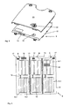
- FIG. 1 therefore shows only the lower housing part 1 of the vacuum cleaner.
- This has a suction fan, not shown in the drawings, which is driven by an electric motor, also not shown.
- the fan and the motor are arranged in a motor fan room 2, which is divided by a first partition from a space 4 for receiving a cable drum, not shown, and by a second partition wall 5 of a dust collecting space 6.
- a dust collector not shown, may be arranged in a known manner, either a dust bag, a filter or a container which acts as a centrifugal force, inertia or other separator by its structure.
- a plurality of individual battery cells 9 is arranged in the accumulator package 8.
- these are a total of 24 cells with a single voltage of a maximum of 4.2 volts, so that in a series connection of these cells 9 a total voltage of 100.8 volts maximum is reached.
- the cells 9 are received by an accumulator housing 10. In each case, eight cells 9 are combined to form a cell group which is spatially and electrically separated from the other groups.
- FIG. 5 schematically shows the individual cell groups A, B and C, in which two cells 9.1 are arranged in a lower layer twice and in an upper layer two more cells 9 are packed on the front three cells 9 of the lower layer (see also FIG. 3 ).
- the accumulator package 8 is housed in the vacuum cleaner so that the area with the cells 9 packed one above the other is placed directly below the dust space 6 and consequently in a well-ventilated area, see also FIG. 1 , The area in which only a lower layer is present extends below the engine fan room 2.
- the cell groups A to C are spatially separated by partitions 11, which in the FIGS. 1 and 3 recognizable and in FIG. 5 are indicated schematically.
- the electrical separation of the cell groups A to C is carried out by a special measure:
- the eight cells 9 in a cell group A to C are each electrically contacted with each other, so that each of the three cell groups A to C reaches a cell voltage of 33.6 volts.
- the electrical contacting of the individual cells 9 to form the cell groups A to C takes place internally within the accumulator housing 10 via an in FIG. 5 only schematically indicated, otherwise not shown welding with electrically conductive sheets 12.
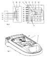
- the cell groups A to C are not connected to each other within the accumulator 8 with each other. Whose individual leads 14 are separated to contacts one in the FIGS. 4 and 5 recognizable connector receptacle 13 out. This is also from the in FIG.
- FIG. 6 illustrated circuit diagram in which the individual terminals are designated by X1 to X8.
- the negative poles of the cell groups A to C occupy the contacts X1 to X3, the positive poles the contacts X6 to X8.
- Figures 5 and 6 show that in the accumulator 10 also an NTC resistor 15, a switch 16 and three fuses 17 are arranged.
- the NTC resistor 15 is used to detect the temperature in the battery pack 8. It is located in the cell group C in the area of the cells 9, which are arranged directly under the engine fan chamber 2. There the highest temperatures are expected.
- the connection lines 18 of the NTC 15 are led to the connection contacts X4 and X5.
- the fuses 17 prevent a permanent short circuit in one of the cell groups A to C.
- the function of the switch 16 in the line 14.1 from the negative pole of the cell group B to the terminal contact X2 will be explained later.
- FIG. 7 shows the bottom of the vacuum cleaner.
- the open receptacle 7 can be seen, in which the accumulator 8 is inserted.
- a plug 19 is provided, which comes by entering the package 8 with the connector receptacle 13 in engagement.
- FIG. 6 It can be seen that on the plug 19 two bridges 20 and 21 are arranged, which connect the contact X1 with X7 and the contact X2 with X8. As a result, all three cell groups A to C are connected in series, so that between the lines Y3 and Y4, the total voltage of 100.8 volts is applied.
- the bridges 20 and 21 it is achieved that only after the connection of the plug 19 with the connector receptacle 13, a voltage is produced which is higher than the safety extra-low voltage of 42 volts.
Landscapes
- Engineering & Computer Science (AREA)
- Power Engineering (AREA)
- Manufacturing & Machinery (AREA)
- Chemical & Material Sciences (AREA)
- Chemical Kinetics & Catalysis (AREA)
- Electrochemistry (AREA)
- General Chemical & Material Sciences (AREA)
- Mechanical Engineering (AREA)
- Electric Vacuum Cleaner (AREA)
- Battery Mounting, Suspending (AREA)
- Charge And Discharge Circuits For Batteries Or The Like (AREA)
Description
- Die Erfindung betrifft ein elektrisches Gerät, insbesondere einen Bodenstaubsauger, mit einem Gehäuse, in dem ein Elektromotor und ein aus mehreren Akkumulatorzellen bestehendes Akkumulatorpaket zu dessen Bestromung angeordnet ist, wobei die Bestromung mit einer Betriebsspannung von mehr als 42 Volt erfolgt, und wobei eine Steckereinrichtung zur elektrischen Kontaktierung des Akkumulatorpakets mit dem Elektromotor vorgesehen ist.
- Ein solches Gerät ist beispielsweise durch die
WO 2007/073864 A2 bekannt. DieDE 20 2006 008 476 U1 offenbart eine Energieversorgung, welche aus mehreren wiederaufladbaren Akkupacks besteht. Diese Akkupacks werden zum Entladen mittels einer Steckverbindung seriell verbunden. - Herkömmliche Elektrogeräte, die durch einen Akkumulator bestromt werden, sind in der Regel für eine Betriebsspannung unter 42 Volt ausgelegt. Dieser Wert entspricht der Sicherheitskleinspannungsgrenze nach VDE 0700. Es gibt Anwendungsfälle, in denen mit einer solchen Betriebsspannung nicht die gewünschte Leistung erreichbar ist, insbesondere wenn die Strombelastung limitiert ist. Als Beispiel seien hier die in der o. g. Patentanmeldung beschriebenen Staubsauger genannt, die sowohl im Netzspannungsbetrieb als auch im Akkubetrieb eine zufriedenstellende Saugleistung erreichen sollen. Es müssen also eine Anzahl von Akkumulatorzellen verwendet werden, die insgesamt eine Betriebsspannung von mehr als 42 Volt erzeugen, vorzugsweise sollte diese Spannung im Bereich um 100 Volt liegen.
- Da ein Personenkontakt zu einer solchen Spannung sowohl bei der Fertigung als auch bei der Handhabung des Geräts vermieden werden muss, kann diesen Personen nicht das von Geräten mit Kleinspannungsverbrauchern (Taschenlampen, Fernsteuerungen etc.) bekannte Handling zugemutet werden. Dort werden die notwendigen Akkumulatorzellen einzeln in einen Aufnahmeraum des Geräts gelegt und über vorhandene Brücken wird dann die elektrische Verbindung der Zellen vorgenommen. Bei einem solchen Vorgehen würde mit jeder eingelegten Zelle die Spannung, mit der der Bediener in Berührung kommen kann, steigen. Auch sogenannte Akkupacks, d. h. mehrere bereits untereinander kontaktierte Zellen in einem festen, unzugänglichen Akkumulatorgehäuse bieten hier keine Lösung, da die zur Kontaktierung des Akkumulatorpakets mit dem Elektromotor notwendigen Steckverbindungen immer noch ein Gefahrenpotential bilden.
- Der Erfindung stellt sich somit das Problem, bei einem elektrischen Gerät der eingangs genannten Art sowohl den Bediener als auch mit der Gerätemontage befasste Personen vor dem Kontakt mit spannungsführenden Teilen zu schützen, an denen mehr als die Sicherheitskleinspannung von 42 Volt anliegt.
- Erfindungsgemäß wird dieses Problem durch ein elektrisches Gerät mit den Merkmalen des Patentanspruchs 1 gelöst. Vorteilhafte Ausgestaltungen und Weiterbildungen der Erfindung ergeben sich aus den nachfolgenden Unteransprüchen.
- Die mit der Erfindung erreichbaren Vorteile bestehen darin, dass auf einfache Weise ein Kontakt mit einer Spannung von mehr als 42 Volt vermieden wird. Dies erfolgt dadurch, dass die Akkumulatorzellen derart miteinander elektrisch kontaktiert sind, dass mindestens zwei Zellengruppen mit einer Zellspannung von weniger als 42 Volt entstehen, und dass die Steckereinrichtung eine Brückenschaltung beinhaltet, welche beim Herstellen der Kontaktierung des Akkumulatorpakets mit dem Elektromotor die Zellgruppen derart miteinander elektrisch kontaktiert, dass diese die Betriebsspannung von mehr als 42 Volt abgeben.
- Dabei ist es zweckmäßig, wenn die Brückenschaltung in ein nicht am Akkumulatorpaket angeordnetes Teil der Steckereinrichtung integriert ist.
- Außerdem ist es zweckmäßig, wenn die Akkumulatorzellen von einem Akkumulatorgehäuse aufgenommen werden, an dem ein Stecker oder ein Steckergehäuse als Teil der Steckereinrichtung angeordnet ist. Um das Akkumulatorpaket vor Überhitzung zu schützen, ist in dem Akkumulatorgehäuse ein Temperatursensor angeordnet, dessen Anschlussleitungen an Anschlusskontakte am Stecker oder am Steckergehäuse geführt sind. Dabei ist es zweckmäßig, wenn der Temperatursensor in einem Bereich des Akkumulatorgehäuses angeordnet ist, welcher dem Elektromotor am nächsten ist.
- Für Lithiumionen-Akkumulatorzellen gibt es eine Gefahrgutvorschrift der UN3090-Transportvorschrift. Danach darf der Lithiumgehalt bei einer Einzelzelle nicht größer als zwei Gramm sein, der Gesamt-Lithiumgehalt bei einem Akkumulatorpaket nicht größer als acht Gramm. Diese Vorschrift wird durch eine räumliche und/oder elektrische Trennung einzelner Zellgruppen erreicht, und zwar dadurch, dass an dem Akkumulatorgehäuse ein Schalter angeordnet ist, mit dem sowohl die elektrische Kontaktierung des Akkumulatorpakets mit dem Elektromotor als auch die elektrische Kontaktierung von zwei Zellgruppen untereinander trennbar ist und/oder dass die einzelnen Zellengruppen innerhalb des Akkumulatorgehäuses durch Zwischenwände voneinander getrennt sind.
- Ein Ausführungsbeispiel der Erfindung ist in den Zeichnungen rein schematisch dargestellt und wird nachfolgend näher beschrieben. Es zeigt
- Figur 1
- eine perspektivische Darstellung eines Staubsauger-Gehäuseunterteils mit einem Aufnahmefach für ein Akkumulatorpaket,
- Figuren 2 bis 4
- das Akkumulatorpaket mit geöffnetem und geschlossenem Gehäuse in verschiedenen Ansichten,
- Figur 5
- eine schematische Darstellung des Akkumulatorpakets
- Figur 6
- die Schaltskizze des Akkumulatorpakets und der Steckereinrichtung,
- Figur 7
- das Aufnahmefach des Staubsaugers bei entferntem Akkumulatorpaket.
- Im Folgenden ist ein erfindungsgemäß aufgebautets elektrisches Gerät anhand eines Staubsaugers beschrieben. Der Gesamtaufbau eines solchen Staubsaugers ist aus der eingangs genannten deutschen Patentanmeldung
102006058613.1 hinreichend bekannt und ist deshalb in den Figuren nicht dargstellt. DieFigur 1 zeigt deshalb nur das Gehäuseunterteil 1 des Staubsaugers. Dieser besitzt ein in den Zeichnungen nicht dargestelltes Sauggebläse, welches über einen ebenfalls nicht dargestellten Elektromotor angetrieben wird. Das Gebläse und der Motor sind in einem Motorgebläseraum 2 angeordnet, der durch eine erste Trennwand von einem Raum 4 zur Aufnahme einer nicht dargestellten Kabeltrommel und durch eine zweite Trennwand 5 von einem Staubsammelraum 6 abgeteilt wird. In dem Staubsammelraum 6 kann in bekannter Weise ein nicht dargestellter Staubabscheider angeordnet sein, entweder ein Staubbeutel, ein Filter oder ein Behälter, der durch seine Struktur als Fliehkraft-, Massenträgheits- oder sonstiger Abscheider wirkt. - In einer Ebene unterhalb des Motorgebläseraums 2 und unterhalb des Staubsammelraums 6 ist in einem Aufnahmefach 7 (siehe auch
Figur 7 ) ein in denFiguren 2 bis 5 dargestelltes Akkumulatorpaket 8 angeordnet, mit dem der Staubsauger unabhängig vom Stromnetz betrieben werden kann. Damit das Gebläse auch bei dieser Betriebsart eine ausreichende Saugleistung erzeugt, ist in dem Akkumulatorpaket 8 eine Vielzahl von einzelnen Akkumulatorzellen 9 angeordnet. Im gezeigten Beispiel sind dies insgesamt 24 Zellen mit einer Einzelspannung von maximal 4,2 Volt, so dass bei einer Reihenschaltung dieser Zellen 9 eine Gesamtspannung von maximal 100,8 Volt erreicht wird. Die Zellen 9 werden von einem Akkumulatorgehäuse 10 aufgenommen. Dabei werden jeweils acht Zellen 9 zu einer Zellengruppe zusammengefasst, die von den anderen Gruppen räumlich und elektrisch getrennt ist.Figur 5 zeigt schematisch die einzelnen Zellengruppen A, B und C, bei denen in einer unteren Schicht zweimal drei Zellen 9.1 arrangiert sind und in einer oberen Schicht nochmals zwei Zellen 9 auf die vorderen drei Zellen 9 der unteren Schicht gepackt werden (siehe auchFigur 3 ). Das Akkumulatorpaket 8 ist im Staubsauger so untergebracht, dass der Bereich mit den übereinander gepackten Zellen 9 direkt unter dem Staubraum 6 und demzufolge in einem gut belüfteten Bereich platziert ist, siehe auchFigur 1 . Der Bereich, in dem nur eine untere Schicht vorhanden ist, erstreckt sich bis unter den Motorgebläseraum 2. Die Zellengruppen A bis C sind durch Zwischenwände 11 räumlich getrennt, die in denFiguren 1 und 3 erkennbar und inFigur 5 schematisch angedeutet sind. Die elektrische Trennung der Zellengruppen A bis C erfolgt durch eine besondere Maßnahme: Die acht Zellen 9 in einer Zellengruppe A bis C sind jeweils miteinander elektrisch kontaktiert, so dass jede der drei Zellengruppen A bis C eine Zellenspannung von 33,6 Volt erreicht. Die elektrische Kontaktierung der einzelnen Zellen 9 zur Bildung der Zellengruppen A bis C erfolgt intern innerhalb des Akkumulatorgehäuses 10 über eine inFigur 5 nur schematisch angedeutete, ansonsten nicht weiter dargestellte Verschweißung mit elektrisch leitenden Blechen 12. Die Zellengruppen A bis C sind aber nicht innerhalb des Akkumulatorpakets 8 miteinander leitend verbunden. Deren einzelne Anschlussleitungen 14 sind getrennt an Kontakte einer in denFiguren 4 und 5 erkennbaren Steckeraufnahme 13 geführt. Dies ist auch aus der inFigur 6 dargestellten Schaltskizze ersichtlich, in der die einzelnen Anschlusskontakte mit X1 bis X8 bezeichnet sind. Die negativen Pole der Zellengruppen A bis C belegen die Kontakte X1 bis X3, die positiven Pole die Kontakte X6 bis X8.Figuren 5 und6 zeigen, dass in dem Akkumulatorgehäuse 10 außerdem ein NTC-Widerstand 15, ein Schalter 16 und drei Schmelzsicherungen 17 angeordnet sind. Der NTC-Widerstand 15 dient zur Erfassung der Temperatur im Akkumulatorpaket 8. Er befindet sich in der Zellengruppe C im Bereich der Zellen 9, die direkt unter dem Motorgebläseraum 2 angeordnet sind. Dort werden die höchsten Temperaturen erwartet. Die Anschlussleitungen 18 des NTC's 15 werden an die Anschlusskontakte X4 und X5 geführt. Die Schmelzsicherungen 17 verhindern einen dauerhaften Kurzschluss in einer der Zellengruppen A bis C. Die Funktion des Schalters 16 in der Leitung 14.1 vom negativen Pol der Zellengruppe B zum Anschlusskontakt X2 wird später erklärt. -
Figur 7 zeigt die Unterseite des Staubsaugers. Dort ist das geöffnete Aufnahmefach 7 erkennbar, in das das Akkumulatorpaket 8 eingelegt wird. Zur elektrischen Kontaktierung des Pakets 8 mit dem Elektromotor ist ein Stecker 19 vorgesehen, der durch Einiegen des Pakets 8 mit der Steckeraufnahme 13 in Eingriff kommt. AusFigur 6 ist ersichtlich, dass an dem Stecker 19 zwei Brücken 20 und 21 angeordnet sind, die den Kontakt X1 mit X7 und den Kontakt X2 mit X8 verbinden. Hierdurch werden alle drei Zellengruppen A bis C in Reihe geschaltet, so dass zwischen den Leitungen Y3 und Y4 die Gesamtspannung von 100,8 Volt anliegt. Durch die Brücken 20 und 21 wird erreicht, dass erst nach der Verbindung des Steckers 19 mit der Steckeraufnahme 13 eine Spannung hergestellt wird, die höher als die Sicherheitskleinspannung von 42 Volt ist. - Weitere Voraussetzung für das Anliegen der Spannung am Elektromotor ist das Schließen des Schalters 16. Dies muss vom Endbenutzer durch Drehen der Stellschraube 22 am Deckel 23 des Aufnahmefachs 7 (siehe
Figur 4 ) vorgenommen werden. Damit wird erst nach dem Transport vom Herstellerwerk zum Endbenutzer die elektrische Trennung der Zellengruppen B und C (in Reihe) von der Zellengruppe A aufgehoben. Somit sind die Transportsvorschriften für Gefahrgut auch dann eingehalten, wenn der äquivalente Lithiumgehalt des gesamten Akkumulatorpakets 8 über dem zulässigen Gesamtgewicht von acht Gramm liegt. - Der äquivalente Lithiumgehalt (LEC) eines Akkumulatorpakets berechnet sich aus
LEC = 0,3 QNenn X NZellen X Gramm/Amperestunden
mit
QNenn = Nennkapazität einer Zelle
NZellen = Anzahl der Zellen des Akkumulatorpakets - Für ein Paket mit 24 Zellen à 1,6 Amperestunden ergibt sich ein äquivalenter Lithiumgehalt von 11,52 Gramm für das Gesamtpaket und 3,84 Gramm pro Zellengruppe. Durch die elektrische und räumliche Trennung der Zellengruppen B und C von der Gruppe A wird somit ein maximaler äquivalenter Lithiumgehalt von 7,68 Gramm erreicht. Somit wird der Grenzwert von acht Gramm nicht überschritten.
Claims (7)
- Elektrisches Gerät, insbesondere Bodenstaubsauger, mit einem Gehäuse (1), in dem ein Elektromotor und ein aus mehreren Akkumulatorzellen (9, 9.1, 9.2) bestehendes Akkumulatorpaket (8) zu dessen Bestromung angeordnet ist, wobei die Bestromung mit einer Betriebsspannung von mehr als 42 Volt erfolgt, und wobei eine Steckereinrichtung (13, 19) zur elektrischen Kontaktierung des Akkumulatorpakets (8) mit dem Elektromotor vorgesehen ist,
dadurch gekennzeichnet,
dass die Akkumulatorzellen (9, 9.1, 9.2) derart miteinander elektrisch kontaktiert sind, dass mindestens zwei Zellengruppen (A, B, C) mit einer Zellspannung von weniger als 42 Volt entstehen, und dass die Steckereinrichtung (13, 19) mindestens eine Brückenschaltung (20, 21) beinhaltet, welche beim Herstellen der Kontaktierung des Akkumulatorpakets (8) mit dem Elektromotor die Zellgruppen derart miteinander elektrisch kontaktiert, dass diese die Betriebsspannung von mehr als 42 Volt abgeben. - Elektrisches Gerät nach Anspruch 1,
dadurch gekennzeichnet,
dass die Brückenschaltung (20, 21) in ein nicht am Akkumulatorpaket (8) angeordnetes Teil (19) der Steckereinrichtung (13, 19) integriert ist. - Elektrisches Gerät nach Anspruch 2,
dadurch gekennzeichnet,
dass die Akkumulatorzellen (9, 9.1, 9.2) von einem Akkumulatorgehäuse (10) aufgenommen werden, an dem ein Stecker (19) oder ein Steckergehäuse (13) als Teil der Steckereinrichtung (20, 21) angeordnet ist. - Elektrisches Gerät nach mindestens einem der vorhergehenden Ansprüche,
dadurch gekennzeichnet,
dass in dem Akkumulatorgehäuse (10) ein Temperatursensor (15) angeordnet ist, dessen Anschlussleitungen (18) an Anschlusskontakte (X4, X5) am Stecker (19) oder am Steckergehäuse (13) geführt sind. - Elektrisches Gerät nach Anspruch 4,
dadurch gekennzeichnet,
dass der Temperatursensor (15) in einem Bereich des Akkumulatorgehäuses (10) angeordnet ist, welcher dem Elektromotor am nächsten ist. - Elektrisches Gerät nach mindestens einem der vorhergehenden Ansprüche,
dadurch gekennzeichnet,
dass an dem Akkumulatorgehäuse (10) ein Schalter (16) angeordnet ist, mit dem sowohl die elektrische Kontaktierung des Akkumulatorpakets (8) mit dem Elektromotor als auch die elektrische Kontaktierung von zwei Zellgruppen (A, B) untereinander trennbar ist. - Elektrisches Gerät nach mindestens einem der vorhergehenden Ansprüche 3 bis 6,
dadurch gekennzeichnet,
dass die einzelnen Zellengruppen (A, B, C) innerhalb des Akkumulatorgehäuses (10) durch Zwischenwände (11) voneinander getrennt sind.
Applications Claiming Priority (2)
| Application Number | Priority Date | Filing Date | Title |
|---|---|---|---|
| DE102008017092 | 2008-04-02 | ||
| PCT/EP2009/002285 WO2009121532A1 (de) | 2008-04-02 | 2009-03-28 | Elektrisches gerät mit elektromotor und akkumulatorpaket |
Publications (2)
| Publication Number | Publication Date |
|---|---|
| EP2269263A1 EP2269263A1 (de) | 2011-01-05 |
| EP2269263B1 true EP2269263B1 (de) | 2013-01-16 |
Family
ID=40743864
Family Applications (1)
| Application Number | Title | Priority Date | Filing Date |
|---|---|---|---|
| EP09728952A Active EP2269263B1 (de) | 2008-04-02 | 2009-03-28 | Elektrisches gerät mit elektromotor und akkumulatorpaket |
Country Status (4)
| Country | Link |
|---|---|
| US (1) | US8424152B2 (de) |
| EP (1) | EP2269263B1 (de) |
| DK (1) | DK2269263T3 (de) |
| WO (1) | WO2009121532A1 (de) |
Cited By (1)
| Publication number | Priority date | Publication date | Assignee | Title |
|---|---|---|---|---|
| EP2945205B1 (de) | 2014-05-12 | 2017-10-18 | LG Electronics Inc. | Staubsauger |
Families Citing this family (2)
| Publication number | Priority date | Publication date | Assignee | Title |
|---|---|---|---|---|
| DE102010041318A1 (de) * | 2010-09-24 | 2012-03-29 | Zumtobel Lighting Gmbh | Vorrichtung zur Notstromversorgung |
| KR102246769B1 (ko) * | 2016-11-07 | 2021-04-30 | 삼성에스디아이 주식회사 | 배터리 팩 및 이를 포함하는 전기 청소기 |
Family Cites Families (10)
| Publication number | Priority date | Publication date | Assignee | Title |
|---|---|---|---|---|
| SE461249B (sv) * | 1988-06-06 | 1990-01-29 | Electrolux Ab | Batterimatad ytbehandlingsapparat med boosterfunktion |
| DE4234231A1 (de) | 1992-10-10 | 1994-04-14 | Adolf Wuerth Gmbh & Co Kg | Wiederaufladbarer Akku |
| US6448732B1 (en) * | 1999-08-10 | 2002-09-10 | Pacific Steamex Cleaning Systems, Inc. | Dual mode portable suction cleaner |
| US6457205B1 (en) * | 2000-05-24 | 2002-10-01 | Fantom Technologies Inc. | Vacuum cleaner having a plurality of power modes |
| DE102005010124B3 (de) | 2005-03-02 | 2006-10-19 | Miele & Cie. Kg | Staubsauger, insbesondere Bodenstaubsauger |
| CN101326703A (zh) | 2005-11-23 | 2008-12-17 | 麦太保有限公司 | 用于与用电器连接的蓄电池 |
| ITMO20050321A1 (it) * | 2005-11-29 | 2007-05-30 | Massimiliano Pineschi | Elettrodomestico portatile |
| DE102006058613B4 (de) | 2006-12-11 | 2013-01-31 | Miele & Cie. Kg | Staubsauger, dessen Gebläsemotor sowohl im Akkumulator-Betrieb als auch im Netzspannungs-Betrieb bestrombar ist |
| EP2163180A3 (de) | 2005-12-19 | 2014-03-12 | Miele & Cie. KG | Staubsauger, insbesondere Bodenstaubsauger |
| DE202006008476U1 (de) | 2006-05-29 | 2006-08-10 | Winkler, Udo | Transportable Energieversorgung |
-
2009
- 2009-03-28 DK DK09728952.4T patent/DK2269263T3/da active
- 2009-03-28 WO PCT/EP2009/002285 patent/WO2009121532A1/de not_active Ceased
- 2009-03-28 EP EP09728952A patent/EP2269263B1/de active Active
- 2009-03-28 US US12/935,200 patent/US8424152B2/en active Active
Cited By (2)
| Publication number | Priority date | Publication date | Assignee | Title |
|---|---|---|---|---|
| EP2945205B1 (de) | 2014-05-12 | 2017-10-18 | LG Electronics Inc. | Staubsauger |
| EP2945205B2 (de) † | 2014-05-12 | 2022-04-27 | LG Electronics Inc. | Staubsauger |
Also Published As
| Publication number | Publication date |
|---|---|
| EP2269263A1 (de) | 2011-01-05 |
| US8424152B2 (en) | 2013-04-23 |
| WO2009121532A1 (de) | 2009-10-08 |
| DK2269263T3 (da) | 2013-03-18 |
| US20110023264A1 (en) | 2011-02-03 |
Similar Documents
| Publication | Publication Date | Title |
|---|---|---|
| DE102008017424B4 (de) | Elektrisches Gerät mit einem Akkumulatorpaket zur Stromversorgung eines elektrischen Verbrauchers | |
| EP2406838B1 (de) | Batteriesystem mit einer ausgangsspannung von mehr als 60 v gleichspannung | |
| DE102011108009A1 (de) | Batterie mit sich wiederholendem Rahmen mit Verbinden von Zellenlaschen mittels angeschweissten Gleitsitzstift- und Buchsenverbindern | |
| DE102015105426A1 (de) | Sicherheitsvorrichtung für einen wiederaufladbaren elektrischen Energiespeicher | |
| DE102009057368A1 (de) | Elektrochemischer Energiespeicher und Anordnung einer Mehrzahl solcher elektrochemischen Energiespeicher | |
| EP2953183A2 (de) | Stecksystem zur kombination von lithium- akkumulatoren und deren verbindung zu einem batteriesystem | |
| DE102010013024A1 (de) | Batterie aus einer Vielzahl von Batterieeinzelzellen | |
| DE102009013727A1 (de) | Batterie mit einem Stapel aus Flachzellen, Rahmen zur Halterung einer Flachzelle und Fahrzeug mit einer solchen Batterie | |
| EP2269263B1 (de) | Elektrisches gerät mit elektromotor und akkumulatorpaket | |
| EP2534715B1 (de) | Energiespeicheranordnung und energiespeichervorrichtung | |
| DE102019216545A1 (de) | Hochvoltbatterie eines Kraftfahrzeugs | |
| WO2022152496A1 (de) | Batteriemodul, modulares batteriesystem und verfahren zur montage eines modularen batteriesystems | |
| WO2013087742A2 (de) | Akkumulator und verfahren zu dessen herstellung | |
| EP3079223B1 (de) | Batteriesystem zur elektrischen verbindung mit einer komponente | |
| DE102015105429B4 (de) | Energieversorgungsvorrichtung, Batteriemanagementsystem und Verfahren zum Betreiben eines Batteriemanagementsystems | |
| DE102017124153B4 (de) | Verfahren und System zum Betreiben von mehreren in einem Elektrogerät eingesetzten Akkupacks | |
| WO2016206794A1 (de) | Stellantrieb mit einer notenergieversorgungseinrichtung, verfahren zu dessen betrieb sowie verwendung einer notenergieversorgungseinrichtung an einem stellantrieb | |
| WO2019096640A1 (de) | Kraftfahrzeug mit einem energiespeicher sowie verfahren zum betreiben eines kraftfahrzeugs | |
| DE102012201844A1 (de) | Vorladung einer Kapazität eines elektrischen Verbrauchers aus einem galvanisch getrennten elektrischen Energiespeicher | |
| WO2014094744A1 (de) | Batteriesystem mit batteriemanagementsystem, speichersystem zur speicherung elektrischer energie mit einem solchen batteriesystem und verfahren zur inbetriebnahme eines solchen batteriesystems | |
| DE102021210157A1 (de) | Schnittstellenmodul zum Betreiben eines elektrischen Verbrauchers mit zumindest einem wechselbaren Energiespeicher sowie Verfahren zur Ansteuerung des elektrischen Verbrauchers mittels des Schnittstellenmoduls | |
| EP2913882B1 (de) | Batterieüberwachungssystem, Batterieanordnung mit dem Batterieüberwachungssystem und Verfahren zum Betreiben der Batterieanordnung | |
| WO2013034226A1 (de) | Verfahren zum fertigen einer hochvoltbatterie und batterieanordnung | |
| WO2012123139A2 (de) | Energiespeicher und energiespeichersystem | |
| DE102013010155A1 (de) | Batteriesystem mit Batteriemanagementsystem, Speichersystem zur Speicherung elektrischer Energie mit einem solchen Batteriesystem und Verfahren zur Inbetriebnahme eines solchen Batteriesystems |
Legal Events
| Date | Code | Title | Description |
|---|---|---|---|
| PUAI | Public reference made under article 153(3) epc to a published international application that has entered the european phase |
Free format text: ORIGINAL CODE: 0009012 |
|
| 17P | Request for examination filed |
Effective date: 20101022 |
|
| AK | Designated contracting states |
Kind code of ref document: A1 Designated state(s): AT BE BG CH CY CZ DE DK EE ES FI FR GB GR HR HU IE IS IT LI LT LU LV MC MK MT NL NO PL PT RO SE SI SK TR |
|
| AX | Request for extension of the european patent |
Extension state: AL BA RS |
|
| DAX | Request for extension of the european patent (deleted) | ||
| GRAP | Despatch of communication of intention to grant a patent |
Free format text: ORIGINAL CODE: EPIDOSNIGR1 |
|
| GRAS | Grant fee paid |
Free format text: ORIGINAL CODE: EPIDOSNIGR3 |
|
| GRAA | (expected) grant |
Free format text: ORIGINAL CODE: 0009210 |
|
| AK | Designated contracting states |
Kind code of ref document: B1 Designated state(s): AT BE BG CH CY CZ DE DK EE ES FI FR GB GR HR HU IE IS IT LI LT LU LV MC MK MT NL NO PL PT RO SE SI SK TR |
|
| REG | Reference to a national code |
Ref country code: GB Ref legal event code: FG4D Free format text: NOT ENGLISH |
|
| REG | Reference to a national code |
Ref country code: CH Ref legal event code: EP |
|
| REG | Reference to a national code |
Ref country code: IE Ref legal event code: FG4D Free format text: LANGUAGE OF EP DOCUMENT: GERMAN |
|
| REG | Reference to a national code |
Ref country code: AT Ref legal event code: REF Ref document number: 594324 Country of ref document: AT Kind code of ref document: T Effective date: 20130215 Ref country code: CH Ref legal event code: EP |
|
| REG | Reference to a national code |
Ref country code: DE Ref legal event code: R096 Ref document number: 502009006048 Country of ref document: DE Effective date: 20130307 |
|
| REG | Reference to a national code |
Ref country code: DK Ref legal event code: T3 |
|
| REG | Reference to a national code |
Ref country code: DE Ref legal event code: R084 Ref document number: 502009006048 Country of ref document: DE Effective date: 20130124 |
|
| REG | Reference to a national code |
Ref country code: NL Ref legal event code: VDEP Effective date: 20130116 |
|
| REG | Reference to a national code |
Ref country code: LT Ref legal event code: MG4D |
|
| PG25 | Lapsed in a contracting state [announced via postgrant information from national office to epo] |
Ref country code: SE Free format text: LAPSE BECAUSE OF FAILURE TO SUBMIT A TRANSLATION OF THE DESCRIPTION OR TO PAY THE FEE WITHIN THE PRESCRIBED TIME-LIMIT Effective date: 20130116 Ref country code: NO Free format text: LAPSE BECAUSE OF FAILURE TO SUBMIT A TRANSLATION OF THE DESCRIPTION OR TO PAY THE FEE WITHIN THE PRESCRIBED TIME-LIMIT Effective date: 20130416 Ref country code: BG Free format text: LAPSE BECAUSE OF FAILURE TO SUBMIT A TRANSLATION OF THE DESCRIPTION OR TO PAY THE FEE WITHIN THE PRESCRIBED TIME-LIMIT Effective date: 20130416 Ref country code: ES Free format text: LAPSE BECAUSE OF FAILURE TO SUBMIT A TRANSLATION OF THE DESCRIPTION OR TO PAY THE FEE WITHIN THE PRESCRIBED TIME-LIMIT Effective date: 20130427 Ref country code: IS Free format text: LAPSE BECAUSE OF FAILURE TO SUBMIT A TRANSLATION OF THE DESCRIPTION OR TO PAY THE FEE WITHIN THE PRESCRIBED TIME-LIMIT Effective date: 20130516 Ref country code: LT Free format text: LAPSE BECAUSE OF FAILURE TO SUBMIT A TRANSLATION OF THE DESCRIPTION OR TO PAY THE FEE WITHIN THE PRESCRIBED TIME-LIMIT Effective date: 20130116 |
|
| PG25 | Lapsed in a contracting state [announced via postgrant information from national office to epo] |
Ref country code: GR Free format text: LAPSE BECAUSE OF FAILURE TO SUBMIT A TRANSLATION OF THE DESCRIPTION OR TO PAY THE FEE WITHIN THE PRESCRIBED TIME-LIMIT Effective date: 20130417 Ref country code: PT Free format text: LAPSE BECAUSE OF FAILURE TO SUBMIT A TRANSLATION OF THE DESCRIPTION OR TO PAY THE FEE WITHIN THE PRESCRIBED TIME-LIMIT Effective date: 20130516 Ref country code: FI Free format text: LAPSE BECAUSE OF FAILURE TO SUBMIT A TRANSLATION OF THE DESCRIPTION OR TO PAY THE FEE WITHIN THE PRESCRIBED TIME-LIMIT Effective date: 20130116 Ref country code: PL Free format text: LAPSE BECAUSE OF FAILURE TO SUBMIT A TRANSLATION OF THE DESCRIPTION OR TO PAY THE FEE WITHIN THE PRESCRIBED TIME-LIMIT Effective date: 20130116 Ref country code: SI Free format text: LAPSE BECAUSE OF FAILURE TO SUBMIT A TRANSLATION OF THE DESCRIPTION OR TO PAY THE FEE WITHIN THE PRESCRIBED TIME-LIMIT Effective date: 20130116 Ref country code: NL Free format text: LAPSE BECAUSE OF FAILURE TO SUBMIT A TRANSLATION OF THE DESCRIPTION OR TO PAY THE FEE WITHIN THE PRESCRIBED TIME-LIMIT Effective date: 20130116 Ref country code: LV Free format text: LAPSE BECAUSE OF FAILURE TO SUBMIT A TRANSLATION OF THE DESCRIPTION OR TO PAY THE FEE WITHIN THE PRESCRIBED TIME-LIMIT Effective date: 20130116 |
|
| BERE | Be: lapsed |
Owner name: MIELE & CIE. K.G. Effective date: 20130331 |
|
| PG25 | Lapsed in a contracting state [announced via postgrant information from national office to epo] |
Ref country code: HR Free format text: LAPSE BECAUSE OF FAILURE TO SUBMIT A TRANSLATION OF THE DESCRIPTION OR TO PAY THE FEE WITHIN THE PRESCRIBED TIME-LIMIT Effective date: 20130116 |
|
| PG25 | Lapsed in a contracting state [announced via postgrant information from national office to epo] |
Ref country code: CZ Free format text: LAPSE BECAUSE OF FAILURE TO SUBMIT A TRANSLATION OF THE DESCRIPTION OR TO PAY THE FEE WITHIN THE PRESCRIBED TIME-LIMIT Effective date: 20130116 Ref country code: SK Free format text: LAPSE BECAUSE OF FAILURE TO SUBMIT A TRANSLATION OF THE DESCRIPTION OR TO PAY THE FEE WITHIN THE PRESCRIBED TIME-LIMIT Effective date: 20130116 Ref country code: MC Free format text: LAPSE BECAUSE OF NON-PAYMENT OF DUE FEES Effective date: 20130331 Ref country code: EE Free format text: LAPSE BECAUSE OF FAILURE TO SUBMIT A TRANSLATION OF THE DESCRIPTION OR TO PAY THE FEE WITHIN THE PRESCRIBED TIME-LIMIT Effective date: 20130116 Ref country code: RO Free format text: LAPSE BECAUSE OF FAILURE TO SUBMIT A TRANSLATION OF THE DESCRIPTION OR TO PAY THE FEE WITHIN THE PRESCRIBED TIME-LIMIT Effective date: 20130116 |
|
| REG | Reference to a national code |
Ref country code: CH Ref legal event code: PL |
|
| PLBE | No opposition filed within time limit |
Free format text: ORIGINAL CODE: 0009261 |
|
| STAA | Information on the status of an ep patent application or granted ep patent |
Free format text: STATUS: NO OPPOSITION FILED WITHIN TIME LIMIT |
|
| REG | Reference to a national code |
Ref country code: HU Ref legal event code: AG4A Ref document number: E017160 Country of ref document: HU |
|
| PG25 | Lapsed in a contracting state [announced via postgrant information from national office to epo] |
Ref country code: CY Free format text: LAPSE BECAUSE OF FAILURE TO SUBMIT A TRANSLATION OF THE DESCRIPTION OR TO PAY THE FEE WITHIN THE PRESCRIBED TIME-LIMIT Effective date: 20130116 |
|
| 26N | No opposition filed |
Effective date: 20131017 |
|
| REG | Reference to a national code |
Ref country code: IE Ref legal event code: MM4A |
|
| PG25 | Lapsed in a contracting state [announced via postgrant information from national office to epo] |
Ref country code: IE Free format text: LAPSE BECAUSE OF NON-PAYMENT OF DUE FEES Effective date: 20130328 Ref country code: LI Free format text: LAPSE BECAUSE OF NON-PAYMENT OF DUE FEES Effective date: 20130331 Ref country code: BE Free format text: LAPSE BECAUSE OF NON-PAYMENT OF DUE FEES Effective date: 20130331 Ref country code: CH Free format text: LAPSE BECAUSE OF NON-PAYMENT OF DUE FEES Effective date: 20130331 |
|
| REG | Reference to a national code |
Ref country code: DE Ref legal event code: R097 Ref document number: 502009006048 Country of ref document: DE Effective date: 20131017 |
|
| PG25 | Lapsed in a contracting state [announced via postgrant information from national office to epo] |
Ref country code: MT Free format text: LAPSE BECAUSE OF FAILURE TO SUBMIT A TRANSLATION OF THE DESCRIPTION OR TO PAY THE FEE WITHIN THE PRESCRIBED TIME-LIMIT Effective date: 20130116 |
|
| PGFP | Annual fee paid to national office [announced via postgrant information from national office to epo] |
Ref country code: HU Payment date: 20150317 Year of fee payment: 7 Ref country code: DK Payment date: 20150325 Year of fee payment: 7 |
|
| REG | Reference to a national code |
Ref country code: AT Ref legal event code: MM01 Ref document number: 594324 Country of ref document: AT Kind code of ref document: T Effective date: 20140328 |
|
| PG25 | Lapsed in a contracting state [announced via postgrant information from national office to epo] |
Ref country code: TR Free format text: LAPSE BECAUSE OF FAILURE TO SUBMIT A TRANSLATION OF THE DESCRIPTION OR TO PAY THE FEE WITHIN THE PRESCRIBED TIME-LIMIT Effective date: 20130116 |
|
| PG25 | Lapsed in a contracting state [announced via postgrant information from national office to epo] |
Ref country code: MK Free format text: LAPSE BECAUSE OF FAILURE TO SUBMIT A TRANSLATION OF THE DESCRIPTION OR TO PAY THE FEE WITHIN THE PRESCRIBED TIME-LIMIT Effective date: 20130116 Ref country code: LU Free format text: LAPSE BECAUSE OF NON-PAYMENT OF DUE FEES Effective date: 20130328 |
|
| PG25 | Lapsed in a contracting state [announced via postgrant information from national office to epo] |
Ref country code: AT Free format text: LAPSE BECAUSE OF NON-PAYMENT OF DUE FEES Effective date: 20140328 |
|
| REG | Reference to a national code |
Ref country code: FR Ref legal event code: PLFP Year of fee payment: 8 |
|
| REG | Reference to a national code |
Ref country code: DK Ref legal event code: EBP Effective date: 20160331 |
|
| PG25 | Lapsed in a contracting state [announced via postgrant information from national office to epo] |
Ref country code: HU Free format text: LAPSE BECAUSE OF NON-PAYMENT OF DUE FEES Effective date: 20160329 |
|
| REG | Reference to a national code |
Ref country code: FR Ref legal event code: PLFP Year of fee payment: 9 |
|
| PG25 | Lapsed in a contracting state [announced via postgrant information from national office to epo] |
Ref country code: DK Free format text: LAPSE BECAUSE OF NON-PAYMENT OF DUE FEES Effective date: 20160331 |
|
| REG | Reference to a national code |
Ref country code: FR Ref legal event code: PLFP Year of fee payment: 10 |
|
| PGFP | Annual fee paid to national office [announced via postgrant information from national office to epo] |
Ref country code: FR Payment date: 20230323 Year of fee payment: 15 |
|
| PGFP | Annual fee paid to national office [announced via postgrant information from national office to epo] |
Ref country code: IT Payment date: 20230321 Year of fee payment: 15 Ref country code: GB Payment date: 20230321 Year of fee payment: 15 |
|
| P01 | Opt-out of the competence of the unified patent court (upc) registered |
Effective date: 20230529 |
|
| GBPC | Gb: european patent ceased through non-payment of renewal fee |
Effective date: 20240328 |
|
| PG25 | Lapsed in a contracting state [announced via postgrant information from national office to epo] |
Ref country code: GB Free format text: LAPSE BECAUSE OF NON-PAYMENT OF DUE FEES Effective date: 20240328 |
|
| PG25 | Lapsed in a contracting state [announced via postgrant information from national office to epo] |
Ref country code: FR Free format text: LAPSE BECAUSE OF NON-PAYMENT OF DUE FEES Effective date: 20240331 |
|
| PG25 | Lapsed in a contracting state [announced via postgrant information from national office to epo] |
Ref country code: GB Free format text: LAPSE BECAUSE OF NON-PAYMENT OF DUE FEES Effective date: 20240328 Ref country code: FR Free format text: LAPSE BECAUSE OF NON-PAYMENT OF DUE FEES Effective date: 20240331 |
|
| PG25 | Lapsed in a contracting state [announced via postgrant information from national office to epo] |
Ref country code: IT Free format text: LAPSE BECAUSE OF NON-PAYMENT OF DUE FEES Effective date: 20240328 |
|
| PGFP | Annual fee paid to national office [announced via postgrant information from national office to epo] |
Ref country code: DE Payment date: 20260331 Year of fee payment: 18 |