EP2269052B1 - Method for the remote detection, localization and monitoring of critical faults in pipelines - Google Patents
Method for the remote detection, localization and monitoring of critical faults in pipelines Download PDFInfo
- Publication number
- EP2269052B1 EP2269052B1 EP09734531.8A EP09734531A EP2269052B1 EP 2269052 B1 EP2269052 B1 EP 2269052B1 EP 09734531 A EP09734531 A EP 09734531A EP 2269052 B1 EP2269052 B1 EP 2269052B1
- Authority
- EP
- European Patent Office
- Prior art keywords
- fault
- pipeline
- sensors
- acoustic
- passive
- Prior art date
- Legal status (The legal status is an assumption and is not a legal conclusion. Google has not performed a legal analysis and makes no representation as to the accuracy of the status listed.)
- Active
Links
Images


Classifications
-
- G—PHYSICS
- G01—MEASURING; TESTING
- G01N—INVESTIGATING OR ANALYSING MATERIALS BY DETERMINING THEIR CHEMICAL OR PHYSICAL PROPERTIES
- G01N29/00—Investigating or analysing materials by the use of ultrasonic, sonic or infrasonic waves; Visualisation of the interior of objects by transmitting ultrasonic or sonic waves through the object
- G01N29/04—Analysing solids
- G01N29/07—Analysing solids by measuring propagation velocity or propagation time of acoustic waves
-
- G—PHYSICS
- G01—MEASURING; TESTING
- G01N—INVESTIGATING OR ANALYSING MATERIALS BY DETERMINING THEIR CHEMICAL OR PHYSICAL PROPERTIES
- G01N29/00—Investigating or analysing materials by the use of ultrasonic, sonic or infrasonic waves; Visualisation of the interior of objects by transmitting ultrasonic or sonic waves through the object
- G01N29/14—Investigating or analysing materials by the use of ultrasonic, sonic or infrasonic waves; Visualisation of the interior of objects by transmitting ultrasonic or sonic waves through the object using acoustic emission techniques
-
- G—PHYSICS
- G01—MEASURING; TESTING
- G01N—INVESTIGATING OR ANALYSING MATERIALS BY DETERMINING THEIR CHEMICAL OR PHYSICAL PROPERTIES
- G01N29/00—Investigating or analysing materials by the use of ultrasonic, sonic or infrasonic waves; Visualisation of the interior of objects by transmitting ultrasonic or sonic waves through the object
- G01N29/44—Processing the detected response signal, e.g. electronic circuits specially adapted therefor
- G01N29/4472—Mathematical theories or simulation
-
- G—PHYSICS
- G01—MEASURING; TESTING
- G01N—INVESTIGATING OR ANALYSING MATERIALS BY DETERMINING THEIR CHEMICAL OR PHYSICAL PROPERTIES
- G01N2291/00—Indexing codes associated with group G01N29/00
- G01N2291/01—Indexing codes associated with the measuring variable
- G01N2291/011—Velocity or travel time
-
- G—PHYSICS
- G01—MEASURING; TESTING
- G01N—INVESTIGATING OR ANALYSING MATERIALS BY DETERMINING THEIR CHEMICAL OR PHYSICAL PROPERTIES
- G01N2291/00—Indexing codes associated with group G01N29/00
- G01N2291/10—Number of transducers
- G01N2291/106—Number of transducers one or more transducer arrays
-
- G—PHYSICS
- G01—MEASURING; TESTING
- G01N—INVESTIGATING OR ANALYSING MATERIALS BY DETERMINING THEIR CHEMICAL OR PHYSICAL PROPERTIES
- G01N2291/00—Indexing codes associated with group G01N29/00
- G01N2291/26—Scanned objects
- G01N2291/263—Surfaces
- G01N2291/2634—Surfaces cylindrical from outside
Definitions
- the present invention relates to a method for the remote detection, localization and monitoring of critical faults in pipelines.
- the present invention relates to a method for the remote detection, localization and monitoring of critical faults in pipelines either underground or sealines suitable for transporting gas or hydrocarbon liquids, such as natural gas (methane), petroleum or hydrocarbon derivatives of petroleum or water, fresh or salt water, particularly well production water.
- gas or hydrocarbon liquids such as natural gas (methane), petroleum or hydrocarbon derivatives of petroleum or water, fresh or salt water, particularly well production water.
- the present invention relates to a method for the remote monitoring of the structural integrity of gas ducts/oil ducts (pipelines) by the detection of acoustic emissions due to the formation of faults in the pipeline, the linear localization of the fault on the same and monitoring with time to control the development of the faults thus identified.
- acoustic sensors for the remote detection, monitoring and localisation of critical faults is known from WO 98/57166 and US 4,641,526 .
- the transportation of these products through pipelines is only substantially continuous because, for maintenance purposes, the pipelines must be periodically controlled.
- the flow of fluid is periodically interrupted, or substantially reduced, to allow the operators to introduce suitable devices inside the pipeline for detecting the possible formation of critical faults (for example cracks or corrosion points) and monitoring the development of those previously detected.
- the risk of the crack formation in the material of a pipeline is due to reasons associated with the fluid transported and also to external causes.
- the risk factor is linked to the pressure jumps of the fluid transported which cause radial expansions and contractions of the pipe which, with time, can cause the formation of faults due to fatigue stress.
- the pipeline is underground or resting on sea/lake bottoms, these are subject to movement of the earth or sea currents which tend to deform them.
- control and monitoring system of pipelines currently in use has at least one evident drawback, in addition to that previously mentioned with respect to the necessity of interrupting or reducing the flow of fluid transported to allow the introduction and subsequent recovery of control devices. If, in fact, the presence of a fault in the material of the pipeline being examined is discovered, by means of these control devices, this can and will have to be monitored discontinuously, periodically, with the relative stoppages/reductions in the flow of fluid transported inside the pipeline.
- An objective of the present invention is to provide a method for the detection, localization and monitoring of critical faults in underground and underwater pipelines, suitable for transporting gas or hydrocarbon liquids, such as for example, natural gas (methane), petroleum or hydrocarbon derivatives of petroleum, well-production water, etc., which does not have the drawbacks mentioned above and allows the formation of a critical fault to be identified at the moment of its formation, with the continuous monitoring of the possible development of the fault, without intervening on the flow-rate of the fluid transported. In this way, an operator can repair the section of pipeline involved when the fault has become such as to endanger the integrity of the pipeline itself.
- gas or hydrocarbon liquids such as for example, natural gas (methane), petroleum or hydrocarbon derivatives of petroleum, well-production water, etc.
- the method developed takes into consideration some important factors such as the characteristics of the pipeline and the materials used, indicating, in the calculation for the localization of the fault, two or more propagation rate ranges which vary with a variation in the relative distance between the fault-source and the acoustic sensors installed on the pipeline.
- An object of the present invention therefore relates to a method for the remote detection, localization and monitoring of critical faults in underground or underwater pipelines, according to claim 1.
- Such a method comprises:
- service state of the sensor refers to a measurement of the receptive function of the passive sensors which is in relation to the service time and work conditions.
- One or more active acoustic sensors can be used for the purpose, which are capable of emitting, on command, ultrasounds that are comparable with those emitted from a real fault which is formed "ab initio" in the pipeline or which are emitted from a fault already present in the pipeline and which evolves with time.
- the periodical activation of said active sensors not only allows the service state of the passive sensors to be controlled, but also allows the periodical calibration of the whole monitoring system, object of the present invention.
- the identification of the formation of a critical fault or the monitoring of a pre-existing fault can be effected on any type of pipeline even if it is preferable to apply the method, object of the present invention, on underground pipelines or pipelines deposited on sea/lake bottoms, as, once functioning, they are only accessible with programmed recovery and maintenance interventions.
- Examples of pipes are those made of carbon steel with diameters of up to 150 cm, for example from 10 to 130 cm, possibly coated with protective materials of a plastic nature fixed to the metal by thermowelding or by hot-melt adhesives.
- the acoustic sensors can be arranged over the whole length of the pipeline at predefined intervals. For economical reasons, however, it is preferable to arrange them in correspondence with potentially critical sections such as weldings, curves, sections subject to stress due to the ground movement, etc. Once the potentially critical sections have been identified, the sensors are generally arranged over lengths of 800-1,500 m of pipeline, at distances from each other of 10 to 50 m, preferably from 20 to 40 m, generally at a distance of 30 m.
- the sensors can be arranged in a straight line on the section of pipeline of interest, along a generating linea or around a pipeline according to a substantially helicoidal line.
- the sensors can be arranged around each of a plurality of fixed positions spaced linearly from each other.
- the distance between each sensor is preferably always the same, then the software takes into account the distances between the sensors for processing the signals.
- Any acoustic sensor capable of detecting the diffusion of sound waves (ultrasounds) on steel pipes, possibly coated with protective material of a plastic nature, can be used in the method, object of the present invention, even if acoustic sensors of the piezoelectric type are preferred as they are selective for that range of sound frequencies (30-600 kHz).
- Alternative acoustic sensors can be electromagnetic transducers or "magnetostrictive" transducers.
- the propagation rate of the sound wave resulting from the formation of a critical fault on the pipeline, or from the development of a fault under control, depends on the position in which it is formed, whether superficially, outside the pipeline or inside the pipeline, or in the thickness of the pipe.
- the propagation velocity is influenced by the materials, generally by the protection material of the pipeline (in the case of a fault on the outer surface) or by the fluid transported (in the case of a fault on the inner surface).
- the signals received at least from a first closer sensor and from at least a second more distant sensor, transformed into electric signals in situ, are transmitted to a data collection centre, transformed into digital signals and remotely sent where a process unit processes them to identify their origin, particularly if on the right or left of said at least a first closer sensor and the distance from said at least second more distant sensor.
- the software allows the determination of the position of the fault and the definition of the statistic relations for its monitoring:
- the calculation of the position of a fault is the main action of the software. This depends on the definition, in an acoustic sense, of the materials which form the pipeline or which flow through it.
- a material is generally characterized by two parameters: the acoustic velocity and the acoustic attenuation.
- the former is the propagation velocity of the elastic waves and is calculated from the measured propagation time, also called time of flight, or it is the time necessary for the sound to go through a certain dimension of the material.
- the second is a measurement of the loss of energy of the sound wave.
- the near field is the region of space where the transmission velocity resulting from the advancing of the sound wave is characterized by a maximum transmission value, V 1 .
- the acoustic pressure of the emission is dampened as the emission point moves away from the acoustic sensor.
- the far field is the area in which the acoustic pressure decreases up to a bottom plateau value characterized by a velocity V 2 .
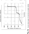
- Figure 1 is a general representation of the transmission phenomenon.
- Figure 1 indicates, in the ordinate, the resulting values of the acoustic velocities calculated by means of passive sensors following the emissions, one at a time, of active sensors, during a calibration period.
- the relative distance is indicated between the sensors in the calibration process.
- Curves are traced on the graph, which indicate the calculation functions of the velocity of the acoustic signal in the domain of the relative distances between the sensors.
- a descriptive type of the velocity function of the acoustic signal in Figure 1 requires a minimum of two average velocity transmission values, V 1 and V 2 , valid in the distance fields between the emission point and the receiving sensor, for x ⁇ L 1 and for x>L 2 , respectively.
- FIG. 2 An iterative calculation process scheme of the position of a fault, by means of the velocity distribution of Figure 1 , is indicated in Figure 2 .
- the scheme in Figure 2 represents a research process of the velocity of the transmission phenomenon based on the definition range of the velocity function described in Figure 1 .
- the scheme considers the following steps:
- the position of a fault detected by various sensors is obtained following a triangulation approach between "n" distances of the fault from the fixed positions of the "n” sensors which have revealed its emission event.
- various sensors are necessary for the present invention. Some of these, called active sensors, are used as sound wave sources for the calibration phase of the measurement process through passive sensors (receivers).
- the detections of the acoustic phenomenon induced in the calibration is therefore a complex function of material parameters through which the sound waves pass and, implicitly, of the specific set-up of the single sensor.
- the calibration process defines the transmission phenomenon between different positions along the pipeline.
- the sensors can be applied on the pipeline according to any known method. It is preferable however to apply them on the pipeline through a specific method which comprises:
- the supporting plate can be rectangular or square and can have a pass-through opening wherein the acoustic sensor is inserted so that it can rest in contact with the metal or the coating of the pipeline.
- a spring is positioned above the sensor, in order to prevent the sensor from moving during the operation and, therefore, no longer having an adequate contact with the pipeline, so that when the box is inserted and is fixed to the supporting plate, the spring exerts, through the top of the box, a pressure force which acts on the acoustic sensor keeping it blocked in its original position.
- the covering box is fixed to the supporting plate by means of screws which are engaged in threaded holes present on the plate itself.
- the top of the box can be integral, and not separable from the walls of the box or it can be extracted and fixed to the walls of the box by suitable fixing means, for example screws.
- the plate is fixed to the pipeline, partially by welding and partially through the overturned L-shaped flanges shaped.
- the latter are situated (welded only on the outer surface of the pipeline) so as to keep the plate pressed against the pipe.
- This arrangement does not allow upward movements of the plate, but only longitudinal sliding movements which second the radial elastic deformations of the pipeline, in particular the radial elastic deformations due to the pressure jumps of the fluid transported.
- step (iii), which constrains the supporting plate to the pipeline can be different, with no welding of the edge and containment in correspondence with the other of the L-shaped flanges.
- the edges of the plates orthogonal to the axis of the pipeline can be shaped to respectively receive two belts which are tightened around the pipeline.
- At least two spring elements are respectively positioned between the belt and each shaped part of the two edges of the plate, which allow the plate to follow the radial movements of the pipeline when subjected, for example, to the above radial deformations.
- the belts In order to avoid damage to the acoustic sensor and/or the associated electronics, due to possible escape currents or electric discharges from atmospheric events, it is preferable for the belts not to be metallic but made of electrically non-conductive materials. Belts made of thermoplastic polymers, polyethylene or polypropylene, reinforced with glass and/or Kevlar® fibres, can be used for the purpose.
- the pipeline was filled with water at about 100 bar of pressure and then subjected to approximately 6,000 continuous pressure cycles in order to monitor the degenerative development of the notches. The test was carried out for about 24 months, until the degeneration of the notches caused the explosion of the pipeline.
- Figure 3a shows in the ordinate, the linear determination of the position of a fault on the pipeline over a period of time.
- Figure 3b represents in the ordinate, the cumulated emission, over a period of time, coming from the fault (ordinate of Figure 3a ).
- the case refers to a known fault on the matrix of the pipeline.
- the characteristic of a fault which grows with time is represented by an emission having small variations in the position on the pipeline, for ever-increasing emission values in the module during the monitoring time.
Landscapes
- Physics & Mathematics (AREA)
- General Physics & Mathematics (AREA)
- Pathology (AREA)
- Life Sciences & Earth Sciences (AREA)
- Chemical & Material Sciences (AREA)
- Analytical Chemistry (AREA)
- Biochemistry (AREA)
- General Health & Medical Sciences (AREA)
- Health & Medical Sciences (AREA)
- Immunology (AREA)
- Acoustics & Sound (AREA)
- Mathematical Optimization (AREA)
- Mathematical Analysis (AREA)
- Algebra (AREA)
- Mathematical Physics (AREA)
- Pure & Applied Mathematics (AREA)
- Engineering & Computer Science (AREA)
- Signal Processing (AREA)
- Investigating Or Analyzing Materials By The Use Of Ultrasonic Waves (AREA)
- Examining Or Testing Airtightness (AREA)
- Pipeline Systems (AREA)
- Length Measuring Devices Characterised By Use Of Acoustic Means (AREA)
- Measurement Of Velocity Or Position Using Acoustic Or Ultrasonic Waves (AREA)
Priority Applications (2)
| Application Number | Priority Date | Filing Date | Title |
|---|---|---|---|
| PL09734531T PL2269052T3 (pl) | 2008-04-24 | 2009-04-09 | Sposób zdalnego wykrywania, lokalizacji i monitorowania uszkodzeń krytycznych w rurociągach |
| HRP20200313TT HRP20200313T1 (hr) | 2008-04-24 | 2009-04-09 | Metoda za daljinsku detekciju, lokalizaciju i praćenje kritičnih nedostataka u cjevovodima |
Applications Claiming Priority (2)
| Application Number | Priority Date | Filing Date | Title |
|---|---|---|---|
| IT000759A ITMI20080759A1 (it) | 2008-04-24 | 2008-04-24 | Metodo per la rilevazione localizzazione e monitoraggio di difetti critici in tubazioni da remoto |
| PCT/EP2009/002776 WO2009129959A1 (en) | 2008-04-24 | 2009-04-09 | Method for the remote detection, localization and monitoring of critical faults in pipelines |
Publications (2)
| Publication Number | Publication Date |
|---|---|
| EP2269052A1 EP2269052A1 (en) | 2011-01-05 |
| EP2269052B1 true EP2269052B1 (en) | 2019-12-11 |
Family
ID=40297009
Family Applications (1)
| Application Number | Title | Priority Date | Filing Date |
|---|---|---|---|
| EP09734531.8A Active EP2269052B1 (en) | 2008-04-24 | 2009-04-09 | Method for the remote detection, localization and monitoring of critical faults in pipelines |
Country Status (11)
| Country | Link |
|---|---|
| US (1) | US8381593B2 (pl) |
| EP (1) | EP2269052B1 (pl) |
| CA (1) | CA2721160C (pl) |
| CY (1) | CY1122830T1 (pl) |
| DK (1) | DK2269052T3 (pl) |
| EA (1) | EA021964B1 (pl) |
| HR (1) | HRP20200313T1 (pl) |
| HU (1) | HUE048634T2 (pl) |
| IT (1) | ITMI20080759A1 (pl) |
| PL (1) | PL2269052T3 (pl) |
| WO (1) | WO2009129959A1 (pl) |
Families Citing this family (18)
| Publication number | Priority date | Publication date | Assignee | Title |
|---|---|---|---|---|
| JP5501700B2 (ja) * | 2009-09-09 | 2014-05-28 | 三菱重工業株式会社 | 被災範囲推定装置及びプログラム |
| US8483007B2 (en) * | 2010-10-18 | 2013-07-09 | Eaton Corporation | Acoustic sensor system for detecting electrical conductivity faults in an electrical distribution system |
| GB2491804B (en) | 2011-05-11 | 2018-01-17 | Syrinix Ltd | Pipeline fault detection system and monitor unit |
| US10191016B2 (en) * | 2012-05-16 | 2019-01-29 | Hidden Solutions Llc | Method and system for passive detection, localization and characterization of mechanical wave sources using ultrasonic guided waves |
| GB2513094B (en) | 2013-02-14 | 2019-03-13 | Syrinix Ltd | Pipeline pressure transient event monitoring unit and method |
| CA2928146A1 (en) * | 2013-12-04 | 2015-06-11 | Halliburton Energy Services, Inc. | Deposit build-up monitoring, identification and removal optimization for conduits |
| RU2673367C2 (ru) * | 2014-04-18 | 2018-11-26 | Эни С.П.А. | Способ и система для непрерывного дистанционного контроля деформаций в находящемся под давлением трубопроводе |
| US9756231B2 (en) | 2015-02-27 | 2017-09-05 | I&Eye Enterprises, LLC | Wastewater monitoring system and method |
| US10602040B2 (en) | 2015-02-27 | 2020-03-24 | I&Eye Enterprises, LLC | Wastewater monitoring system and method |
| US11300855B2 (en) | 2015-02-27 | 2022-04-12 | l&Eye Enterprises, LLC | Wastewater monitoring system and method |
| DE102016211651B4 (de) * | 2016-06-28 | 2022-03-24 | Bender Gmbh & Co. Kg | Verfahren zum Bestimmen eines Isolationsfehlerortes auf einem elektrischen Leiter einer Untermeeresversorgungsleitung |
| GB2597763A (en) | 2020-08-04 | 2022-02-09 | Syrinix Ltd | Transient pressure event detection system and method |
| RU2739715C1 (ru) * | 2020-08-12 | 2020-12-28 | Общество с ограниченной ответственностью «Татнефть-Пресскомпозит» | Способ определения срока безопасной эксплуатации стеклопластиковых трубопроводов |
| US12000740B2 (en) | 2020-11-17 | 2024-06-04 | Board Of Trustees Of Michigan State University | Sensor apparatus |
| US11525809B2 (en) * | 2020-12-04 | 2022-12-13 | Perceptive Sensor Technologies, Inc. | Apparatus, system, and method for the detection of objects and activity within a container |
| KR102528544B1 (ko) * | 2021-05-13 | 2023-05-09 | 주식회사 아이디케이 | 음향방출 신호를 이용한 결함 위치 진단 방법 |
| US11895387B2 (en) | 2022-07-08 | 2024-02-06 | I & EyeEnterprises, LLC | Modular camera that uses artificial intelligence to categorize photos |
| US12035025B2 (en) | 2022-07-08 | 2024-07-09 | I & EyeEnterprises, LLC | Modular camera |
Family Cites Families (11)
| Publication number | Priority date | Publication date | Assignee | Title |
|---|---|---|---|---|
| JPS5642114A (en) * | 1979-09-14 | 1981-04-20 | Chugoku Electric Power Co Ltd:The | Detection method for loose parts |
| FR2494848A1 (fr) * | 1980-11-24 | 1982-05-28 | Technigaz | Procede et dispositif de detection, a distance, de defauts d'etancheite d'une conduite de transport d'un fluide, immergee dans un fluide ambiant; conduite de transport comprenant ce dispositif de detection et procede de construction d'une telle conduite |
| JPS59225374A (ja) * | 1983-06-06 | 1984-12-18 | Hitachi Ltd | 音源位置標定方法とその装置 |
| FR2646239B1 (fr) * | 1989-04-24 | 1991-08-16 | Dassault Avions | Procede et dispositif acoustique de localisation de defauts du materiau constituant une piece et emetteur acoustique utilisable dans ce dispositif |
| US5127267A (en) * | 1991-01-18 | 1992-07-07 | Southern California Gas Company | Acoustic method for locating concealed pipe |
| AU8005998A (en) * | 1997-06-11 | 1998-12-30 | Pure Technologies Ltd. | Method and apparatus for monitoring of tensioned cables |
| GB9720720D0 (en) * | 1997-10-01 | 1997-11-26 | Rolls Royce Plc | An apparatus and a method for locating a source of acoustic emissions in an article |
| US6728662B2 (en) * | 2002-02-15 | 2004-04-27 | Radiodetection Limited | Method and system for remotely servicing a detection device |
| GB2416207B (en) * | 2004-07-15 | 2008-08-27 | Ultra Electronics Ltd | Acoustic structural integrity monitoring system and method |
| DE102005036508B4 (de) * | 2005-07-29 | 2007-07-12 | Eupec Pipecoatings Gmbh | Verfahren und Vorrichtung zur Überwachung und Detektierung von Beschichtungsdefekten einer erd- oder wasserverlegten Rohrleitung |
| US8087311B2 (en) * | 2007-02-28 | 2012-01-03 | Merlo Stephen A | Remote pipe inspection using a mounted camera and sensor |
-
2008
- 2008-04-24 IT IT000759A patent/ITMI20080759A1/it unknown
-
2009
- 2009-04-09 PL PL09734531T patent/PL2269052T3/pl unknown
- 2009-04-09 WO PCT/EP2009/002776 patent/WO2009129959A1/en not_active Ceased
- 2009-04-09 EP EP09734531.8A patent/EP2269052B1/en active Active
- 2009-04-09 HU HUE09734531A patent/HUE048634T2/hu unknown
- 2009-04-09 CA CA2721160A patent/CA2721160C/en active Active
- 2009-04-09 DK DK09734531.8T patent/DK2269052T3/da active
- 2009-04-09 US US12/988,751 patent/US8381593B2/en active Active
- 2009-04-09 HR HRP20200313TT patent/HRP20200313T1/hr unknown
- 2009-04-09 EA EA201001535A patent/EA021964B1/ru not_active IP Right Cessation
-
2020
- 2020-03-06 CY CY20201100204T patent/CY1122830T1/el unknown
Non-Patent Citations (1)
| Title |
|---|
| None * |
Also Published As
| Publication number | Publication date |
|---|---|
| EP2269052A1 (en) | 2011-01-05 |
| CA2721160C (en) | 2016-09-20 |
| ITMI20080759A1 (it) | 2009-10-25 |
| HUE048634T2 (hu) | 2020-08-28 |
| CY1122830T1 (el) | 2021-05-05 |
| CA2721160A1 (en) | 2009-10-29 |
| US20110114412A1 (en) | 2011-05-19 |
| HRP20200313T1 (hr) | 2020-06-12 |
| EA021964B1 (ru) | 2015-10-30 |
| DK2269052T3 (da) | 2020-03-09 |
| WO2009129959A1 (en) | 2009-10-29 |
| US8381593B2 (en) | 2013-02-26 |
| EA201001535A1 (ru) | 2011-06-30 |
| PL2269052T3 (pl) | 2020-06-01 |
Similar Documents
| Publication | Publication Date | Title |
|---|---|---|
| EP2269052B1 (en) | Method for the remote detection, localization and monitoring of critical faults in pipelines | |
| EP3335036B1 (en) | Detection and monitoring of changes in metallic structures using acoustic signals | |
| US10996203B2 (en) | Detection, monitoring, and determination of location of changes in metallic structures using multimode acoustic signals | |
| EP2269053B1 (en) | Method for the elastic installation of detection devices on pipelines | |
| US9921129B2 (en) | Method and system for the continuous remote monitoring of deformations in a pressurized pipeline | |
| US10585069B2 (en) | Detection, monitoring, and determination of location of changes in metallic structures using multimode acoustic signals | |
| US20170268950A1 (en) | An apparatus and method for measuring the pressure inside a pipe or container | |
| EP3151037A1 (en) | Systems and methods for evaluating annular material using beamforming from acoustic arrays | |
| Anastasopoulos et al. | ACOUSTIC EMISSION LEAK DETECTION OF LIQUID FILLED BURIED PIPELINE. | |
| EP3785027B1 (en) | Detection, monitoring, and determination of location of changes in metallic structures using multimode acoustic signals | |
| Tafuri | Locating leaks with acoustic technology | |
| Mariani et al. | Performance of a guided wave pipe monitoring system over extended periods of field operation | |
| Giunta et al. | De Lorenzo et a].(45) Date of Patent: Oct. 8, 2013 | |
| Saifullin et al. | Methods of Leak Search from Pipeline for Acoustic Signal Analysis | |
| RU2825120C1 (ru) | Способ акустического неразрушающего контроля протяженных конструкций и устройство для его реализации | |
| Liao et al. | A method for identifying free span of subsea pipelines | |
| Pierozzi et al. | Acoustic technology for large obstruction detection in pipelines | |
| US20240241008A1 (en) | System and method for determining the location of a leak within a longitudinal pipe | |
| Anderson et al. | Pipeline Integrity And Rehabilitation Technology: An Operator¿ s Perspective | |
| Ortiz et al. | Use of Piezoelectric and Magnetostrictive Guided Wave Ultrasonic Monitoring Technologies on Underground Piping | |
| Martini et al. | Investigation on the detection of water leaks in small-diameter polyethylene pipes using Acoustic Emission signals | |
| Crompton et al. | Guided Wave Testing: Maximizing Buried Pipe Corrosion Knowledge From Each Excavation |
Legal Events
| Date | Code | Title | Description |
|---|---|---|---|
| PUAI | Public reference made under article 153(3) epc to a published international application that has entered the european phase |
Free format text: ORIGINAL CODE: 0009012 |
|
| 17P | Request for examination filed |
Effective date: 20101007 |
|
| AK | Designated contracting states |
Kind code of ref document: A1 Designated state(s): AT BE BG CH CY CZ DE DK EE ES FI FR GB GR HR HU IE IS IT LI LT LU LV MC MK MT NL NO PL PT RO SE SI SK TR |
|
| AX | Request for extension of the european patent |
Extension state: AL BA RS |
|
| DAX | Request for extension of the european patent (deleted) | ||
| STAA | Information on the status of an ep patent application or granted ep patent |
Free format text: STATUS: EXAMINATION IS IN PROGRESS |
|
| 17Q | First examination report despatched |
Effective date: 20180413 |
|
| GRAP | Despatch of communication of intention to grant a patent |
Free format text: ORIGINAL CODE: EPIDOSNIGR1 |
|
| STAA | Information on the status of an ep patent application or granted ep patent |
Free format text: STATUS: GRANT OF PATENT IS INTENDED |
|
| INTG | Intention to grant announced |
Effective date: 20190205 |
|
| GRAJ | Information related to disapproval of communication of intention to grant by the applicant or resumption of examination proceedings by the epo deleted |
Free format text: ORIGINAL CODE: EPIDOSDIGR1 |
|
| STAA | Information on the status of an ep patent application or granted ep patent |
Free format text: STATUS: EXAMINATION IS IN PROGRESS |
|
| GRAP | Despatch of communication of intention to grant a patent |
Free format text: ORIGINAL CODE: EPIDOSNIGR1 |
|
| STAA | Information on the status of an ep patent application or granted ep patent |
Free format text: STATUS: GRANT OF PATENT IS INTENDED |
|
| INTC | Intention to grant announced (deleted) | ||
| INTG | Intention to grant announced |
Effective date: 20190701 |
|
| GRAS | Grant fee paid |
Free format text: ORIGINAL CODE: EPIDOSNIGR3 |
|
| GRAA | (expected) grant |
Free format text: ORIGINAL CODE: 0009210 |
|
| STAA | Information on the status of an ep patent application or granted ep patent |
Free format text: STATUS: THE PATENT HAS BEEN GRANTED |
|
| AK | Designated contracting states |
Kind code of ref document: B1 Designated state(s): AT BE BG CH CY CZ DE DK EE ES FI FR GB GR HR HU IE IS IT LI LT LU LV MC MK MT NL NO PL PT RO SE SI SK TR |
|
| REG | Reference to a national code |
Ref country code: GB Ref legal event code: FG4D |
|
| REG | Reference to a national code |
Ref country code: CH Ref legal event code: EP |
|
| REG | Reference to a national code |
Ref country code: AT Ref legal event code: REF Ref document number: 1212689 Country of ref document: AT Kind code of ref document: T Effective date: 20191215 |
|
| REG | Reference to a national code |
Ref country code: DE Ref legal event code: R096 Ref document number: 602009060681 Country of ref document: DE |
|
| REG | Reference to a national code |
Ref country code: IE Ref legal event code: FG4D |
|
| REG | Reference to a national code |
Ref country code: HR Ref legal event code: TUEP Ref document number: P20200313 Country of ref document: HR |
|
| REG | Reference to a national code |
Ref country code: RO Ref legal event code: EPE |
|
| REG | Reference to a national code |
Ref country code: DK Ref legal event code: T3 Effective date: 20200303 |
|
| REG | Reference to a national code |
Ref country code: NL Ref legal event code: FP |
|
| REG | Reference to a national code |
Ref country code: LT Ref legal event code: MG4D Ref country code: NO Ref legal event code: T2 Effective date: 20191211 |
|
| PG25 | Lapsed in a contracting state [announced via postgrant information from national office to epo] |
Ref country code: GR Free format text: LAPSE BECAUSE OF FAILURE TO SUBMIT A TRANSLATION OF THE DESCRIPTION OR TO PAY THE FEE WITHIN THE PRESCRIBED TIME-LIMIT Effective date: 20200312 Ref country code: FI Free format text: LAPSE BECAUSE OF FAILURE TO SUBMIT A TRANSLATION OF THE DESCRIPTION OR TO PAY THE FEE WITHIN THE PRESCRIBED TIME-LIMIT Effective date: 20191211 Ref country code: LT Free format text: LAPSE BECAUSE OF FAILURE TO SUBMIT A TRANSLATION OF THE DESCRIPTION OR TO PAY THE FEE WITHIN THE PRESCRIBED TIME-LIMIT Effective date: 20191211 Ref country code: LV Free format text: LAPSE BECAUSE OF FAILURE TO SUBMIT A TRANSLATION OF THE DESCRIPTION OR TO PAY THE FEE WITHIN THE PRESCRIBED TIME-LIMIT Effective date: 20191211 Ref country code: SE Free format text: LAPSE BECAUSE OF FAILURE TO SUBMIT A TRANSLATION OF THE DESCRIPTION OR TO PAY THE FEE WITHIN THE PRESCRIBED TIME-LIMIT Effective date: 20191211 Ref country code: ES Free format text: LAPSE BECAUSE OF FAILURE TO SUBMIT A TRANSLATION OF THE DESCRIPTION OR TO PAY THE FEE WITHIN THE PRESCRIBED TIME-LIMIT Effective date: 20191211 |
|
| REG | Reference to a national code |
Ref country code: HR Ref legal event code: ODRP Ref document number: P20200313 Country of ref document: HR Payment date: 20200403 Year of fee payment: 12 |
|
| REG | Reference to a national code |
Ref country code: HR Ref legal event code: T1PR Ref document number: P20200313 Country of ref document: HR |
|
| PG25 | Lapsed in a contracting state [announced via postgrant information from national office to epo] |
Ref country code: EE Free format text: LAPSE BECAUSE OF FAILURE TO SUBMIT A TRANSLATION OF THE DESCRIPTION OR TO PAY THE FEE WITHIN THE PRESCRIBED TIME-LIMIT Effective date: 20191211 Ref country code: PT Free format text: LAPSE BECAUSE OF FAILURE TO SUBMIT A TRANSLATION OF THE DESCRIPTION OR TO PAY THE FEE WITHIN THE PRESCRIBED TIME-LIMIT Effective date: 20200506 Ref country code: CZ Free format text: LAPSE BECAUSE OF FAILURE TO SUBMIT A TRANSLATION OF THE DESCRIPTION OR TO PAY THE FEE WITHIN THE PRESCRIBED TIME-LIMIT Effective date: 20191211 |
|
| REG | Reference to a national code |
Ref country code: HU Ref legal event code: AG4A Ref document number: E048634 Country of ref document: HU |
|
| PG25 | Lapsed in a contracting state [announced via postgrant information from national office to epo] |
Ref country code: SK Free format text: LAPSE BECAUSE OF FAILURE TO SUBMIT A TRANSLATION OF THE DESCRIPTION OR TO PAY THE FEE WITHIN THE PRESCRIBED TIME-LIMIT Effective date: 20191211 Ref country code: IS Free format text: LAPSE BECAUSE OF FAILURE TO SUBMIT A TRANSLATION OF THE DESCRIPTION OR TO PAY THE FEE WITHIN THE PRESCRIBED TIME-LIMIT Effective date: 20200411 |
|
| REG | Reference to a national code |
Ref country code: DE Ref legal event code: R097 Ref document number: 602009060681 Country of ref document: DE |
|
| PLBE | No opposition filed within time limit |
Free format text: ORIGINAL CODE: 0009261 |
|
| STAA | Information on the status of an ep patent application or granted ep patent |
Free format text: STATUS: NO OPPOSITION FILED WITHIN TIME LIMIT |
|
| 26N | No opposition filed |
Effective date: 20200914 |
|
| PG25 | Lapsed in a contracting state [announced via postgrant information from national office to epo] |
Ref country code: MC Free format text: LAPSE BECAUSE OF FAILURE TO SUBMIT A TRANSLATION OF THE DESCRIPTION OR TO PAY THE FEE WITHIN THE PRESCRIBED TIME-LIMIT Effective date: 20191211 Ref country code: SI Free format text: LAPSE BECAUSE OF FAILURE TO SUBMIT A TRANSLATION OF THE DESCRIPTION OR TO PAY THE FEE WITHIN THE PRESCRIBED TIME-LIMIT Effective date: 20191211 |
|
| REG | Reference to a national code |
Ref country code: CH Ref legal event code: PL |
|
| PG25 | Lapsed in a contracting state [announced via postgrant information from national office to epo] |
Ref country code: CH Free format text: LAPSE BECAUSE OF NON-PAYMENT OF DUE FEES Effective date: 20200430 Ref country code: LU Free format text: LAPSE BECAUSE OF NON-PAYMENT OF DUE FEES Effective date: 20200409 Ref country code: LI Free format text: LAPSE BECAUSE OF NON-PAYMENT OF DUE FEES Effective date: 20200430 |
|
| REG | Reference to a national code |
Ref country code: HR Ref legal event code: ODRP Ref document number: P20200313 Country of ref document: HR Payment date: 20210319 Year of fee payment: 13 |
|
| PG25 | Lapsed in a contracting state [announced via postgrant information from national office to epo] |
Ref country code: IE Free format text: LAPSE BECAUSE OF NON-PAYMENT OF DUE FEES Effective date: 20200409 |
|
| REG | Reference to a national code |
Ref country code: AT Ref legal event code: UEP Ref document number: 1212689 Country of ref document: AT Kind code of ref document: T Effective date: 20191211 |
|
| REG | Reference to a national code |
Ref country code: HR Ref legal event code: ODRP Ref document number: P20200313 Country of ref document: HR Payment date: 20220318 Year of fee payment: 14 |
|
| PG25 | Lapsed in a contracting state [announced via postgrant information from national office to epo] |
Ref country code: TR Free format text: LAPSE BECAUSE OF FAILURE TO SUBMIT A TRANSLATION OF THE DESCRIPTION OR TO PAY THE FEE WITHIN THE PRESCRIBED TIME-LIMIT Effective date: 20191211 Ref country code: MT Free format text: LAPSE BECAUSE OF FAILURE TO SUBMIT A TRANSLATION OF THE DESCRIPTION OR TO PAY THE FEE WITHIN THE PRESCRIBED TIME-LIMIT Effective date: 20191211 |
|
| PG25 | Lapsed in a contracting state [announced via postgrant information from national office to epo] |
Ref country code: MK Free format text: LAPSE BECAUSE OF FAILURE TO SUBMIT A TRANSLATION OF THE DESCRIPTION OR TO PAY THE FEE WITHIN THE PRESCRIBED TIME-LIMIT Effective date: 20191211 |
|
| REG | Reference to a national code |
Ref country code: HR Ref legal event code: ODRP Ref document number: P20200313 Country of ref document: HR Payment date: 20230321 Year of fee payment: 15 |
|
| P01 | Opt-out of the competence of the unified patent court (upc) registered |
Effective date: 20230530 |
|
| REG | Reference to a national code |
Ref country code: HR Ref legal event code: ODRP Ref document number: P20200313 Country of ref document: HR Payment date: 20240320 Year of fee payment: 16 |
|
| REG | Reference to a national code |
Ref country code: HR Ref legal event code: ODRP Ref document number: P20200313 Country of ref document: HR Payment date: 20250402 Year of fee payment: 17 |
|
| PGFP | Annual fee paid to national office [announced via postgrant information from national office to epo] |
Ref country code: NL Payment date: 20250422 Year of fee payment: 17 |
|
| PGFP | Annual fee paid to national office [announced via postgrant information from national office to epo] |
Ref country code: PL Payment date: 20250331 Year of fee payment: 17 Ref country code: DE Payment date: 20250417 Year of fee payment: 17 |
|
| PGFP | Annual fee paid to national office [announced via postgrant information from national office to epo] |
Ref country code: GB Payment date: 20250423 Year of fee payment: 17 Ref country code: DK Payment date: 20250423 Year of fee payment: 17 |
|
| PGFP | Annual fee paid to national office [announced via postgrant information from national office to epo] |
Ref country code: HU Payment date: 20250411 Year of fee payment: 17 Ref country code: NO Payment date: 20250422 Year of fee payment: 17 |
|
| PGFP | Annual fee paid to national office [announced via postgrant information from national office to epo] |
Ref country code: BE Payment date: 20250422 Year of fee payment: 17 Ref country code: IT Payment date: 20250430 Year of fee payment: 17 |
|
| PGFP | Annual fee paid to national office [announced via postgrant information from national office to epo] |
Ref country code: HR Payment date: 20250402 Year of fee payment: 17 |
|
| PGFP | Annual fee paid to national office [announced via postgrant information from national office to epo] |
Ref country code: FR Payment date: 20250428 Year of fee payment: 17 |
|
| PGFP | Annual fee paid to national office [announced via postgrant information from national office to epo] |
Ref country code: BG Payment date: 20250415 Year of fee payment: 17 |
|
| PGFP | Annual fee paid to national office [announced via postgrant information from national office to epo] |
Ref country code: RO Payment date: 20250331 Year of fee payment: 17 Ref country code: AT Payment date: 20250416 Year of fee payment: 17 |
|
| PGFP | Annual fee paid to national office [announced via postgrant information from national office to epo] |
Ref country code: CY Payment date: 20250402 Year of fee payment: 17 |