EP2268850B1 - Anode for cathodic protection - Google Patents
Anode for cathodic protection Download PDFInfo
- Publication number
- EP2268850B1 EP2268850B1 EP09732345.5A EP09732345A EP2268850B1 EP 2268850 B1 EP2268850 B1 EP 2268850B1 EP 09732345 A EP09732345 A EP 09732345A EP 2268850 B1 EP2268850 B1 EP 2268850B1
- Authority
- EP
- European Patent Office
- Prior art keywords
- anode
- insulating polymer
- polymer element
- bars
- previous
- Prior art date
- Legal status (The legal status is an assumption and is not a legal conclusion. Google has not performed a legal analysis and makes no representation as to the accuracy of the status listed.)
- Active
Links
Images


Classifications
-
- C—CHEMISTRY; METALLURGY
- C23—COATING METALLIC MATERIAL; COATING MATERIAL WITH METALLIC MATERIAL; CHEMICAL SURFACE TREATMENT; DIFFUSION TREATMENT OF METALLIC MATERIAL; COATING BY VACUUM EVAPORATION, BY SPUTTERING, BY ION IMPLANTATION OR BY CHEMICAL VAPOUR DEPOSITION, IN GENERAL; INHIBITING CORROSION OF METALLIC MATERIAL OR INCRUSTATION IN GENERAL
- C23F—NON-MECHANICAL REMOVAL OF METALLIC MATERIAL FROM SURFACE; INHIBITING CORROSION OF METALLIC MATERIAL OR INCRUSTATION IN GENERAL; MULTI-STEP PROCESSES FOR SURFACE TREATMENT OF METALLIC MATERIAL INVOLVING AT LEAST ONE PROCESS PROVIDED FOR IN CLASS C23 AND AT LEAST ONE PROCESS COVERED BY SUBCLASS C21D OR C22F OR CLASS C25
- C23F13/00—Inhibiting corrosion of metals by anodic or cathodic protection
- C23F13/02—Inhibiting corrosion of metals by anodic or cathodic protection cathodic; Selection of conditions, parameters or procedures for cathodic protection, e.g. of electrical conditions
- C23F13/06—Constructional parts, or assemblies of cathodic-protection apparatus
- C23F13/08—Electrodes specially adapted for inhibiting corrosion by cathodic protection; Manufacture thereof; Conducting electric current thereto
- C23F13/18—Means for supporting electrodes
-
- C—CHEMISTRY; METALLURGY
- C23—COATING METALLIC MATERIAL; COATING MATERIAL WITH METALLIC MATERIAL; CHEMICAL SURFACE TREATMENT; DIFFUSION TREATMENT OF METALLIC MATERIAL; COATING BY VACUUM EVAPORATION, BY SPUTTERING, BY ION IMPLANTATION OR BY CHEMICAL VAPOUR DEPOSITION, IN GENERAL; INHIBITING CORROSION OF METALLIC MATERIAL OR INCRUSTATION IN GENERAL
- C23F—NON-MECHANICAL REMOVAL OF METALLIC MATERIAL FROM SURFACE; INHIBITING CORROSION OF METALLIC MATERIAL OR INCRUSTATION IN GENERAL; MULTI-STEP PROCESSES FOR SURFACE TREATMENT OF METALLIC MATERIAL INVOLVING AT LEAST ONE PROCESS PROVIDED FOR IN CLASS C23 AND AT LEAST ONE PROCESS COVERED BY SUBCLASS C21D OR C22F OR CLASS C25
- C23F13/00—Inhibiting corrosion of metals by anodic or cathodic protection
- C23F13/02—Inhibiting corrosion of metals by anodic or cathodic protection cathodic; Selection of conditions, parameters or procedures for cathodic protection, e.g. of electrical conditions
- C23F13/06—Constructional parts, or assemblies of cathodic-protection apparatus
- C23F13/08—Electrodes specially adapted for inhibiting corrosion by cathodic protection; Manufacture thereof; Conducting electric current thereto
- C23F13/10—Electrodes characterised by the structure
-
- C—CHEMISTRY; METALLURGY
- C23—COATING METALLIC MATERIAL; COATING MATERIAL WITH METALLIC MATERIAL; CHEMICAL SURFACE TREATMENT; DIFFUSION TREATMENT OF METALLIC MATERIAL; COATING BY VACUUM EVAPORATION, BY SPUTTERING, BY ION IMPLANTATION OR BY CHEMICAL VAPOUR DEPOSITION, IN GENERAL; INHIBITING CORROSION OF METALLIC MATERIAL OR INCRUSTATION IN GENERAL
- C23F—NON-MECHANICAL REMOVAL OF METALLIC MATERIAL FROM SURFACE; INHIBITING CORROSION OF METALLIC MATERIAL OR INCRUSTATION IN GENERAL; MULTI-STEP PROCESSES FOR SURFACE TREATMENT OF METALLIC MATERIAL INVOLVING AT LEAST ONE PROCESS PROVIDED FOR IN CLASS C23 AND AT LEAST ONE PROCESS COVERED BY SUBCLASS C21D OR C22F OR CLASS C25
- C23F2201/00—Type of materials to be protected by cathodic protection
- C23F2201/02—Concrete, e.g. reinforced
Definitions
- the present invention relates to an anode for cathodic protection of reinforced concrete structures.
- the corrosion phenomena affecting reinforced concrete structures are well known to the experts in the field.
- the steel reinforcement inserted in the cementitious structures to improve the mechanical properties thereof normally works in a passivation regime induced by the concrete alkaline environment; however, after some time, the ion migration across the porous surface of the concrete induces a localised attack to the protective passivation film.
- Another form of concrete decay is represented by the phenomenon of carbonatation, i.e. the formation of calcium carbonate by reaction of the lime in the cementitious mixture with atmospheric carbon dioxide: the calcium carbonate lowers the alkali content of the cement (from pH 13.5 to pH 9) bringing iron to an unprotected status.
- cathodic protection of reinforced concrete is carried out by coupling anodic structures of various kinds to the concrete, in whose respect the reinforcement to be protected acts as the cathodic counterelectrode; the electrical currents involved, supplied by an external rectifier, transit across the electrolyte consisting of the porous concrete partially soaked with salty solution.
- the cathodic protection of a reinforcement cage may be achieved by means of a distributed anode system, for instance consisting of an arrangement of mesh strip anodes, installed on the reinforcement cage and electrically insulated from the metal by means of spacers made of plastic or cementitious material.
- the anode system is embedded into the structure during the construction, at the time of casting the concrete.
- a weak direct current typically 1 to 30 mA per m 2 of reinforcement applied to the anode and distributed across the whole structure imposes the cathodic potential required for the reinforcement protection.
- prefabricated insulating spacers of plastic or cementitious material to valve metal anodes in form of mesh strips is for instance disclosed in EP 0534392 , specifying how the spacers are generally secured in a first step to the metal cage to be protected; the anode strips are subsequently secured to the spacers, for instance by insertion in appropriate slits provided in the spacers.
- the step of securing the anode strips to the spacers may be carried out by way of pins, bolts or clips, or by using adhesives. This operation is apparently lengthy and cumbersome, especially in those spots offering a less comfortable installation due to a difficult access or to an insufficient lighting. This operation also presents a certain risk of error, because an accidental mistake in the positioning or in the fixing step may cause the anode strip to be locally put in electrical contact with the metal reinforcement cage.
- the present invention relates to an anode for cathodic protection in form of composite strip
- a conductive element such as a metal substrate provided with a superficial catalytic coating (activated element), and an insulating polymer element continuously integral therewith.
- the composite strip optionally rolled into a coil, can thus be directly unwound or otherwise laid down on the metal cage to be protected with no need for a previous positioning of discrete spacers.
- the continuous coupling between the activated element and the insulating element minimises the risk of accidental contacts between the activated substrate and the metal reinforcement to be protected.
- the composite strip can be prefabricated coupling the activated element and the polymer insulating element by co-lamination or mechanical interlocking, by insertion in a foldable structure or by any other fastening means.
- the metal substrate is a strip of mesh or of solid, punched or expanded sheet of titanium, provided with a superficial catalytic coating.
- the catalytic coating can contain noble metals, optionally in form of oxides.
- the insulating element can be manufactured by moulding starting from a polymer material of various types, for example polyethylene or polypropylene.
- the insulating polymer element is a continuous strip equipped with a multiplicity of holes or openings. This can favour a suitable contact of the concrete, poured in a phase subsequent to the anode positioning, with the activated substrate.
- the openings may have different sizes and geometries, such as to prevent an excessive blinding of the activated substrate, according to the contingent needs.
- the insulating polymer element is a continuous strip provided with a multiplicity of holes or openings consisting of a foldable structure, suitable for housing the activated element in its interior and optionally equipped with fastening means to keep it in the folded position, said fastening means for instance consisting of removable articles such as push buttons, hooks, rivets, bolts or clips.
- the insulating polymer element comprises concave parts dimensioned so as to adapt to the profile of the reinforcement cage to be protected; for instance, each concave part may be arranged so as to match the corresponding bar of the reinforcement cage. This can contribute to hold the composite strip anodes in position during the phase of concrete casting, preventing them from sliding.
- the insulating polymer element is magnetic, which can also contribute to hold the composite strip anodes in position during the phase of concrete casting and prevent them from sliding.
- the insulating polymer element comprises a pair of rails or guides suitable for accommodating or enclosing the edges or the activated element. In this way the resulting composite strip is free of cutting edges, thereby facilitating the handling and positioning thereof.
- the insulating polymer element comprises a continuous polymer strip provided with a multiplicity of holes or openings juxtaposed to the activated element, and a pair of rails suitable for accommodating or enclosing the activated element and the continuous polymer strip juxtaposed thereto.
- the insulating polymer element comprises a coloured pigmentation, which can help its identification at first glance from the activated metal part.
- the insulating polymer element comprises a luminescent pigmentation, for instance phosphorescent, fluorescent or bioluminescent.
- coloured or luminescent pigmentations can be particularly helpful for the installation in poorly lighted spots, allowing to verify more easily the overall alignment of the cathodic protection system, for example in correspondence of the exposed areas or of junction zones of the reinforcement cage.
- a cathodic protection system comprises one or more anodes in form of composite strip according to one of the above illustrated embodiments embedded in a reinforced concrete structure, wherein the composite anodes contact the bars of the reinforcement cage only with the polymer insulating part, the exposed parts of the activated metal substrate being entirely surrounded by concrete.
- FIG. 1 An example of anode for cathodic protection in form of composite strip, as shown in Fig. 1 , is obtained by integral continuous juxtaposition of a conductive element consisting of an activated anode mesh (100) to an insulating polymer element (200) along their whole length; the juxtaposition of the two elements is well visible in Fig. 1A , showing a cross-section view.
- the insulating polymer element (200) is equipped with suitable holes (201) of different diameter, in order to diminish the anode mesh blinding effect;
- Fig. 1C is a top-view of the composite strip as seen from the insulating polymer element (200) side, across whose holes the activated anode mesh (100) is visible.
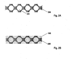
- Fig. 2 shows another embodiment of anode for cathodic protection in form of composite strip, analogous to the one of Fig. 1 but with a different hole arrangement;
- Fig. 2A shows the insulating polymer element (200) equipped with holes (201) alone, according to a top-view, analogously to figure 1B , while
- Fig. 2B shows a top-view of the composite strip as seen from the insulating polymer element (200) side, across whose holes the activated anode mesh (100) is visible, analogously to Fig. 1C .
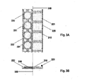
- Fig. 3 shows another embodiment of insulating polymer element for composite strip anode; in particular, Fig. 3A is a top-view of an insulating polymer element consisting of a foldable structure, and Fig 3B is the corresponding cross-section view.
- the insulating element (200) comprises a polymer strip equipped with suitable holes (201) and an assembly of insulating ribbons (210), optionally knurled and provided with a coloured or luminescent pigmentation, integral with the polymer strip and fixed to a rigid edge (220) in a mutually parallel arrangement.
- fastening means are arranged, for instance consisting of a multiplicity of push buttons (221) suitable for cooperating with a multiplicity of seats (222) upon folding the insulating element along its longitudinal axis (300) after insertion of the activated element (not shown).
- This embodiment can have the advantage of allowing the continuous fixing of the activated element to the insulating polymer element by aid of a simple mechanical assemblage operation.
- the use of knurled ribbons can contribute keeping the anode in position during the concrete casting.
- the ribbon pigmentation as described can help reducing the costs by allowing an easier and safer positioning without having to resort to the pigmentation of the whole insulating element.
- Fig. 4 is another embodiment of anode for cathodic protection in form of composite strip, shown in a cross-section in analogy with Fig. 1A .
- the anode is obtained by integral continuous juxtaposition of a conductive element consisting of an activated anode mesh (100) to an insulating polymer element (200) along their whole length; additionally, the insulating polymer element (200) is provided with concave parts (202) suitable for matching the profile of the reinforcement bars of an armed concrete structure.
- Fig. 5 shows a cross-section view of a different embodiment of anode for cathodic protection in form of composite strip; in this case, the insulating polymer element (200) consists of a pair of rails in whose interior the activated anode mesh (100) is inserted.
- an insulating polymer element consisting of a foldable structure equipped with a series of knurled ribbons and with fastening means for restraining the same in the folded position consisting of push buttons; in other embodiments, an insulating polymer element can consist of a foldable structure of different geometry or having different, optionally removable fastening means for restraining the same in the folded position.
- anode comprising a polymer element provided with equally spaced concave parts; in other examples, the anode comprises polymer elements provided with concave parts with a different spacing, for instance in order to better adapt to particular reinforcement cage geometries.
Landscapes
- Chemical & Material Sciences (AREA)
- Engineering & Computer Science (AREA)
- Materials Engineering (AREA)
- Mechanical Engineering (AREA)
- Metallurgy (AREA)
- Organic Chemistry (AREA)
- Prevention Of Electric Corrosion (AREA)
- Paints Or Removers (AREA)
- Superconductors And Manufacturing Methods Therefor (AREA)
- Details Of Television Scanning (AREA)
- Physical Vapour Deposition (AREA)
- Macromolecular Compounds Obtained By Forming Nitrogen-Containing Linkages In General (AREA)
- Electrolytic Production Of Metals (AREA)
Priority Applications (1)
| Application Number | Priority Date | Filing Date | Title |
|---|---|---|---|
| PL09732345T PL2268850T3 (pl) | 2008-04-18 | 2009-04-02 | Anoda do ochrony katodowej |
Applications Claiming Priority (2)
| Application Number | Priority Date | Filing Date | Title |
|---|---|---|---|
| IT000714A ITMI20080714A1 (it) | 2008-04-18 | 2008-04-18 | Anodo per protezione catodica |
| PCT/EP2009/053958 WO2009127530A2 (en) | 2008-04-18 | 2009-04-02 | Anode for cathodic protection |
Publications (2)
| Publication Number | Publication Date |
|---|---|
| EP2268850A2 EP2268850A2 (en) | 2011-01-05 |
| EP2268850B1 true EP2268850B1 (en) | 2015-06-03 |
Family
ID=40296968
Family Applications (1)
| Application Number | Title | Priority Date | Filing Date |
|---|---|---|---|
| EP09732345.5A Active EP2268850B1 (en) | 2008-04-18 | 2009-04-02 | Anode for cathodic protection |
Country Status (16)
Families Citing this family (2)
| Publication number | Priority date | Publication date | Assignee | Title |
|---|---|---|---|---|
| ITMI20101689A1 (it) * | 2010-09-17 | 2012-03-18 | Industrie De Nora Spa | Anodo per protezione catodica e metodo per il suo ottenimento |
| EP2431496A1 (en) * | 2010-09-17 | 2012-03-21 | Soletanche Freyssinet | Composite anode for a cathodic protection system |
Family Cites Families (11)
| Publication number | Priority date | Publication date | Assignee | Title |
|---|---|---|---|---|
| CA2018869A1 (en) * | 1989-07-07 | 1991-01-07 | William A. Kovatch | Mesh anode and mesh separator for use with steel-reinforced concrete |
| RU2014367C1 (ru) * | 1990-08-24 | 1994-06-15 | Всероссийский научно-исследовательский институт по строительству трубопроводов | Анодное заземление |
| CA2075780C (en) | 1991-09-23 | 2002-07-30 | Michele Tettamanti | Anode structure for cathodic protection of steel-reinforced concrete and relevant method of use |
| IT1254287B (it) * | 1992-03-13 | 1995-09-14 | Italcementi Spa | Materiale cementizio di supporto per la protezione catodica di strutture in cemento armato |
| JPH10157002A (ja) * | 1996-11-28 | 1998-06-16 | Nakabohtec Corrosion Protecting Co Ltd | 亜鉛とマグネット含有ゴムまたはプラスチックとの複合材 |
| RU2169210C1 (ru) * | 2000-04-25 | 2001-06-20 | Зорин Анатолий Иванович | Анод для катодной защиты от коррозии и способ формирования активного покрытия анода |
| JP3594295B2 (ja) * | 2000-09-29 | 2004-11-24 | 住友大阪セメント株式会社 | コンクリート構造物の電気防食装置およびコンクリート構造物 |
| JP3779657B2 (ja) * | 2002-08-09 | 2006-05-31 | ショーボンド建設株式会社 | 鉄筋コンクリート構造物の電気防食用電極及び鉄筋コンクリート構造物の電気防食における電気的短絡防止方法 |
| CN100516310C (zh) * | 2004-12-15 | 2009-07-22 | 中国船舶重工集团公司第七二五研究所 | 阴极保护用大排流量阳极组件 |
| JP2006328505A (ja) * | 2005-05-27 | 2006-12-07 | Pacific Consultants Co Ltd | 電気防食装置 |
| JP2007039996A (ja) * | 2005-08-03 | 2007-02-15 | Nippon Steel Composite Co Ltd | コンクリート構造物の補強及び防食方法、並びに、補強・防食材 |
-
2008
- 2008-04-18 IT IT000714A patent/ITMI20080714A1/it unknown
-
2009
- 2009-04-02 MX MX2010011442A patent/MX342112B/es active IP Right Grant
- 2009-04-02 AU AU2009237778A patent/AU2009237778B2/en active Active
- 2009-04-02 KR KR1020107025768A patent/KR101641512B1/ko active Active
- 2009-04-02 EP EP09732345.5A patent/EP2268850B1/en active Active
- 2009-04-02 WO PCT/EP2009/053958 patent/WO2009127530A2/en active Application Filing
- 2009-04-02 JP JP2011504411A patent/JP2011516737A/ja not_active Withdrawn
- 2009-04-02 PL PL09732345T patent/PL2268850T3/pl unknown
- 2009-04-02 DK DK09732345.5T patent/DK2268850T3/en active
- 2009-04-02 RU RU2010146952/02A patent/RU2489521C2/ru active
- 2009-04-02 ES ES09732345.5T patent/ES2545274T3/es active Active
- 2009-04-02 CA CA2720831A patent/CA2720831C/en active Active
- 2009-04-02 CN CN2009801136773A patent/CN102007229B/zh active Active
- 2009-04-02 PT PT97323455T patent/PT2268850E/pt unknown
-
2010
- 2010-10-18 US US12/906,379 patent/US9194047B2/en active Active
- 2010-11-03 MA MA33320A patent/MA32357B1/fr unknown
-
2014
- 2014-07-31 JP JP2014156218A patent/JP5946495B2/ja active Active
Also Published As
| Publication number | Publication date |
|---|---|
| RU2489521C2 (ru) | 2013-08-10 |
| KR20110005877A (ko) | 2011-01-19 |
| US20110024286A1 (en) | 2011-02-03 |
| CN102007229A (zh) | 2011-04-06 |
| RU2010146952A (ru) | 2012-05-27 |
| EP2268850A2 (en) | 2011-01-05 |
| JP2014237895A (ja) | 2014-12-18 |
| DK2268850T3 (en) | 2015-08-31 |
| AU2009237778B2 (en) | 2013-06-13 |
| CN102007229B (zh) | 2012-08-22 |
| CA2720831A1 (en) | 2009-10-22 |
| MX342112B (es) | 2016-09-14 |
| PL2268850T3 (pl) | 2015-11-30 |
| ITMI20080714A1 (it) | 2009-10-19 |
| WO2009127530A2 (en) | 2009-10-22 |
| MX2010011442A (es) | 2010-11-09 |
| ES2545274T3 (es) | 2015-09-09 |
| MA32357B1 (fr) | 2011-06-01 |
| HK1152351A1 (en) | 2012-02-24 |
| US9194047B2 (en) | 2015-11-24 |
| CA2720831C (en) | 2017-07-25 |
| WO2009127530A3 (en) | 2010-03-18 |
| AU2009237778A1 (en) | 2009-10-22 |
| PT2268850E (pt) | 2015-10-01 |
| JP2011516737A (ja) | 2011-05-26 |
| JP5946495B2 (ja) | 2016-07-06 |
| KR101641512B1 (ko) | 2016-07-21 |
Similar Documents
| Publication | Publication Date | Title |
|---|---|---|
| EP2268850B1 (en) | Anode for cathodic protection | |
| CA2031123C (en) | Grid electrode having a tailored surface for cathodic protection of steel reinforced concrete structures | |
| JP5536918B2 (ja) | 鉄筋コンクリートの分離型のカソード防食用アノード | |
| CA2075780C (en) | Anode structure for cathodic protection of steel-reinforced concrete and relevant method of use | |
| HK1152351B (en) | Anode for cathodic protection | |
| CA2302966C (en) | Ladder anode for cathodic protection | |
| NO170291B (no) | Katodisk beskyttet, staalarmert betongkonstruksjon og fremgangsmaate for aa installere en belagt ventilmetallelektrodei et katodisk beskyttelsessystem for en slik konstruksjon | |
| HK1121200B (en) | Discrete anode for cathodic protection of reinforced concrete | |
| NO169299B (no) | Opprullet ventilmetallnetting og anvendelse av denne som anode i utrullet tilstand | |
| SA92130270B1 (ar) | هيكل مصعد للوقاية المهبطية للخرسانة المسلحة بالصلب وطريقة مناسبة لاستخدامه |
Legal Events
| Date | Code | Title | Description |
|---|---|---|---|
| PUAI | Public reference made under article 153(3) epc to a published international application that has entered the european phase |
Free format text: ORIGINAL CODE: 0009012 |
|
| 17P | Request for examination filed |
Effective date: 20101015 |
|
| AK | Designated contracting states |
Kind code of ref document: A2 Designated state(s): AT BE BG CH CY CZ DE DK EE ES FI FR GB GR HR HU IE IS IT LI LT LU LV MC MK MT NL NO PL PT RO SE SI SK TR |
|
| DAX | Request for extension of the european patent (deleted) | ||
| GRAP | Despatch of communication of intention to grant a patent |
Free format text: ORIGINAL CODE: EPIDOSNIGR1 |
|
| INTG | Intention to grant announced |
Effective date: 20141022 |
|
| GRAS | Grant fee paid |
Free format text: ORIGINAL CODE: EPIDOSNIGR3 |
|
| GRAA | (expected) grant |
Free format text: ORIGINAL CODE: 0009210 |
|
| AK | Designated contracting states |
Kind code of ref document: B1 Designated state(s): AT BE BG CH CY CZ DE DK EE ES FI FR GB GR HR HU IE IS IT LI LT LU LV MC MK MT NL NO PL PT RO SE SI SK TR |
|
| REG | Reference to a national code |
Ref country code: GB Ref legal event code: FG4D |
|
| REG | Reference to a national code |
Ref country code: CH Ref legal event code: EP |
|
| REG | Reference to a national code |
Ref country code: AT Ref legal event code: REF Ref document number: 729987 Country of ref document: AT Kind code of ref document: T Effective date: 20150715 Ref country code: IE Ref legal event code: FG4D |
|
| REG | Reference to a national code |
Ref country code: DE Ref legal event code: R096 Ref document number: 602009031552 Country of ref document: DE |
|
| REG | Reference to a national code |
Ref country code: DK Ref legal event code: T3 Effective date: 20150825 |
|
| REG | Reference to a national code |
Ref country code: NL Ref legal event code: T3 |
|
| REG | Reference to a national code |
Ref country code: ES Ref legal event code: FG2A Ref document number: 2545274 Country of ref document: ES Kind code of ref document: T3 Effective date: 20150909 |
|
| REG | Reference to a national code |
Ref country code: SE Ref legal event code: TRGR Ref country code: CH Ref legal event code: NV Representative=s name: FIAMMENGHI-FIAMMENGHI, CH |
|
| REG | Reference to a national code |
Ref country code: PT Ref legal event code: SC4A Free format text: AVAILABILITY OF NATIONAL TRANSLATION Effective date: 20150819 |
|
| PG25 | Lapsed in a contracting state [announced via postgrant information from national office to epo] |
Ref country code: HR Free format text: LAPSE BECAUSE OF FAILURE TO SUBMIT A TRANSLATION OF THE DESCRIPTION OR TO PAY THE FEE WITHIN THE PRESCRIBED TIME-LIMIT Effective date: 20150603 Ref country code: LT Free format text: LAPSE BECAUSE OF FAILURE TO SUBMIT A TRANSLATION OF THE DESCRIPTION OR TO PAY THE FEE WITHIN THE PRESCRIBED TIME-LIMIT Effective date: 20150603 |
|
| REG | Reference to a national code |
Ref country code: NO Ref legal event code: T2 Effective date: 20150603 |
|
| REG | Reference to a national code |
Ref country code: LT Ref legal event code: MG4D |
|
| PG25 | Lapsed in a contracting state [announced via postgrant information from national office to epo] |
Ref country code: LV Free format text: LAPSE BECAUSE OF FAILURE TO SUBMIT A TRANSLATION OF THE DESCRIPTION OR TO PAY THE FEE WITHIN THE PRESCRIBED TIME-LIMIT Effective date: 20150603 Ref country code: BG Free format text: LAPSE BECAUSE OF FAILURE TO SUBMIT A TRANSLATION OF THE DESCRIPTION OR TO PAY THE FEE WITHIN THE PRESCRIBED TIME-LIMIT Effective date: 20150903 Ref country code: GR Free format text: LAPSE BECAUSE OF FAILURE TO SUBMIT A TRANSLATION OF THE DESCRIPTION OR TO PAY THE FEE WITHIN THE PRESCRIBED TIME-LIMIT Effective date: 20150904 |
|
| REG | Reference to a national code |
Ref country code: PL Ref legal event code: T3 |
|
| PG25 | Lapsed in a contracting state [announced via postgrant information from national office to epo] |
Ref country code: EE Free format text: LAPSE BECAUSE OF FAILURE TO SUBMIT A TRANSLATION OF THE DESCRIPTION OR TO PAY THE FEE WITHIN THE PRESCRIBED TIME-LIMIT Effective date: 20150603 |
|
| PG25 | Lapsed in a contracting state [announced via postgrant information from national office to epo] |
Ref country code: SK Free format text: LAPSE BECAUSE OF FAILURE TO SUBMIT A TRANSLATION OF THE DESCRIPTION OR TO PAY THE FEE WITHIN THE PRESCRIBED TIME-LIMIT Effective date: 20150603 Ref country code: CZ Free format text: LAPSE BECAUSE OF FAILURE TO SUBMIT A TRANSLATION OF THE DESCRIPTION OR TO PAY THE FEE WITHIN THE PRESCRIBED TIME-LIMIT Effective date: 20150603 Ref country code: RO Free format text: LAPSE BECAUSE OF NON-PAYMENT OF DUE FEES Effective date: 20150603 Ref country code: IS Free format text: LAPSE BECAUSE OF FAILURE TO SUBMIT A TRANSLATION OF THE DESCRIPTION OR TO PAY THE FEE WITHIN THE PRESCRIBED TIME-LIMIT Effective date: 20151003 |
|
| REG | Reference to a national code |
Ref country code: DE Ref legal event code: R097 Ref document number: 602009031552 Country of ref document: DE |
|
| PLBE | No opposition filed within time limit |
Free format text: ORIGINAL CODE: 0009261 |
|
| STAA | Information on the status of an ep patent application or granted ep patent |
Free format text: STATUS: NO OPPOSITION FILED WITHIN TIME LIMIT |
|
| REG | Reference to a national code |
Ref country code: FR Ref legal event code: PLFP Year of fee payment: 8 |
|
| 26N | No opposition filed |
Effective date: 20160304 |
|
| PG25 | Lapsed in a contracting state [announced via postgrant information from national office to epo] |
Ref country code: SI Free format text: LAPSE BECAUSE OF FAILURE TO SUBMIT A TRANSLATION OF THE DESCRIPTION OR TO PAY THE FEE WITHIN THE PRESCRIBED TIME-LIMIT Effective date: 20150603 |
|
| PG25 | Lapsed in a contracting state [announced via postgrant information from national office to epo] |
Ref country code: LU Free format text: LAPSE BECAUSE OF FAILURE TO SUBMIT A TRANSLATION OF THE DESCRIPTION OR TO PAY THE FEE WITHIN THE PRESCRIBED TIME-LIMIT Effective date: 20160402 |
|
| REG | Reference to a national code |
Ref country code: IE Ref legal event code: MM4A |
|
| REG | Reference to a national code |
Ref country code: AT Ref legal event code: UEP Ref document number: 729987 Country of ref document: AT Kind code of ref document: T Effective date: 20150603 |
|
| REG | Reference to a national code |
Ref country code: FR Ref legal event code: PLFP Year of fee payment: 9 |
|
| PG25 | Lapsed in a contracting state [announced via postgrant information from national office to epo] |
Ref country code: IE Free format text: LAPSE BECAUSE OF NON-PAYMENT OF DUE FEES Effective date: 20160402 |
|
| REG | Reference to a national code |
Ref country code: FR Ref legal event code: PLFP Year of fee payment: 10 |
|
| PG25 | Lapsed in a contracting state [announced via postgrant information from national office to epo] |
Ref country code: HU Free format text: LAPSE BECAUSE OF FAILURE TO SUBMIT A TRANSLATION OF THE DESCRIPTION OR TO PAY THE FEE WITHIN THE PRESCRIBED TIME-LIMIT; INVALID AB INITIO Effective date: 20090402 Ref country code: CY Free format text: LAPSE BECAUSE OF FAILURE TO SUBMIT A TRANSLATION OF THE DESCRIPTION OR TO PAY THE FEE WITHIN THE PRESCRIBED TIME-LIMIT Effective date: 20150603 |
|
| PG25 | Lapsed in a contracting state [announced via postgrant information from national office to epo] |
Ref country code: MT Free format text: LAPSE BECAUSE OF NON-PAYMENT OF DUE FEES Effective date: 20160430 Ref country code: TR Free format text: LAPSE BECAUSE OF FAILURE TO SUBMIT A TRANSLATION OF THE DESCRIPTION OR TO PAY THE FEE WITHIN THE PRESCRIBED TIME-LIMIT Effective date: 20150603 Ref country code: MK Free format text: LAPSE BECAUSE OF FAILURE TO SUBMIT A TRANSLATION OF THE DESCRIPTION OR TO PAY THE FEE WITHIN THE PRESCRIBED TIME-LIMIT Effective date: 20150603 Ref country code: MC Free format text: LAPSE BECAUSE OF FAILURE TO SUBMIT A TRANSLATION OF THE DESCRIPTION OR TO PAY THE FEE WITHIN THE PRESCRIBED TIME-LIMIT Effective date: 20150603 |
|
| PGFP | Annual fee paid to national office [announced via postgrant information from national office to epo] |
Ref country code: PL Payment date: 20240322 Year of fee payment: 16 |
|
| PGFP | Annual fee paid to national office [announced via postgrant information from national office to epo] |
Ref country code: ES Payment date: 20240524 Year of fee payment: 16 |
|
| PGFP | Annual fee paid to national office [announced via postgrant information from national office to epo] |
Ref country code: PT Payment date: 20250320 Year of fee payment: 17 |
|
| PGFP | Annual fee paid to national office [announced via postgrant information from national office to epo] |
Ref country code: NL Payment date: 20250418 Year of fee payment: 17 |
|
| PGFP | Annual fee paid to national office [announced via postgrant information from national office to epo] |
Ref country code: FI Payment date: 20250424 Year of fee payment: 17 |
|
| PGFP | Annual fee paid to national office [announced via postgrant information from national office to epo] |
Ref country code: DE Payment date: 20250422 Year of fee payment: 17 |
|
| PGFP | Annual fee paid to national office [announced via postgrant information from national office to epo] |
Ref country code: GB Payment date: 20250423 Year of fee payment: 17 Ref country code: DK Payment date: 20250429 Year of fee payment: 17 |
|
| PGFP | Annual fee paid to national office [announced via postgrant information from national office to epo] |
Ref country code: NO Payment date: 20250424 Year of fee payment: 17 |
|
| PGFP | Annual fee paid to national office [announced via postgrant information from national office to epo] |
Ref country code: IT Payment date: 20250424 Year of fee payment: 17 Ref country code: BE Payment date: 20250418 Year of fee payment: 17 |
|
| PGFP | Annual fee paid to national office [announced via postgrant information from national office to epo] |
Ref country code: FR Payment date: 20250424 Year of fee payment: 17 |
|
| PGFP | Annual fee paid to national office [announced via postgrant information from national office to epo] |
Ref country code: CH Payment date: 20250501 Year of fee payment: 17 |
|
| PGFP | Annual fee paid to national office [announced via postgrant information from national office to epo] |
Ref country code: AT Payment date: 20250423 Year of fee payment: 17 |
|
| PGFP | Annual fee paid to national office [announced via postgrant information from national office to epo] |
Ref country code: SE Payment date: 20250429 Year of fee payment: 17 |