EP2267709A2 - Recording apparatus, recording method, and disc-shaped record medium - Google Patents
Recording apparatus, recording method, and disc-shaped record medium Download PDFInfo
- Publication number
- EP2267709A2 EP2267709A2 EP10182171A EP10182171A EP2267709A2 EP 2267709 A2 EP2267709 A2 EP 2267709A2 EP 10182171 A EP10182171 A EP 10182171A EP 10182171 A EP10182171 A EP 10182171A EP 2267709 A2 EP2267709 A2 EP 2267709A2
- Authority
- EP
- European Patent Office
- Prior art keywords
- data
- recorded
- area
- recording
- bit map
- Prior art date
- Legal status (The legal status is an assumption and is not a legal conclusion. Google has not performed a legal analysis and makes no representation as to the accuracy of the status listed.)
- Withdrawn
Links
Images


Classifications
-
- G—PHYSICS
- G11—INFORMATION STORAGE
- G11B—INFORMATION STORAGE BASED ON RELATIVE MOVEMENT BETWEEN RECORD CARRIER AND TRANSDUCER
- G11B20/00—Signal processing not specific to the method of recording or reproducing; Circuits therefor
-
- G—PHYSICS
- G11—INFORMATION STORAGE
- G11B—INFORMATION STORAGE BASED ON RELATIVE MOVEMENT BETWEEN RECORD CARRIER AND TRANSDUCER
- G11B27/00—Editing; Indexing; Addressing; Timing or synchronising; Monitoring; Measuring tape travel
- G11B27/10—Indexing; Addressing; Timing or synchronising; Measuring tape travel
- G11B27/19—Indexing; Addressing; Timing or synchronising; Measuring tape travel by using information detectable on the record carrier
- G11B27/28—Indexing; Addressing; Timing or synchronising; Measuring tape travel by using information detectable on the record carrier by using information signals recorded by the same method as the main recording
- G11B27/32—Indexing; Addressing; Timing or synchronising; Measuring tape travel by using information detectable on the record carrier by using information signals recorded by the same method as the main recording on separate auxiliary tracks of the same or an auxiliary record carrier
- G11B27/327—Table of contents
- G11B27/329—Table of contents on a disc [VTOC]
-
- G—PHYSICS
- G11—INFORMATION STORAGE
- G11B—INFORMATION STORAGE BASED ON RELATIVE MOVEMENT BETWEEN RECORD CARRIER AND TRANSDUCER
- G11B20/00—Signal processing not specific to the method of recording or reproducing; Circuits therefor
- G11B20/10—Digital recording or reproducing
- G11B20/12—Formatting, e.g. arrangement of data block or words on the record carriers
- G11B20/1217—Formatting, e.g. arrangement of data block or words on the record carriers on discs
-
- G—PHYSICS
- G11—INFORMATION STORAGE
- G11B—INFORMATION STORAGE BASED ON RELATIVE MOVEMENT BETWEEN RECORD CARRIER AND TRANSDUCER
- G11B20/00—Signal processing not specific to the method of recording or reproducing; Circuits therefor
- G11B20/10—Digital recording or reproducing
- G11B2020/10861—Finalising a record carrier after a recording operation, e.g. to ensure compatibility with a ROM medium
-
- G—PHYSICS
- G11—INFORMATION STORAGE
- G11B—INFORMATION STORAGE BASED ON RELATIVE MOVEMENT BETWEEN RECORD CARRIER AND TRANSDUCER
- G11B20/00—Signal processing not specific to the method of recording or reproducing; Circuits therefor
- G11B20/10—Digital recording or reproducing
- G11B2020/10916—Seeking data on the record carrier for preparing an access to a specific address
-
- G—PHYSICS
- G11—INFORMATION STORAGE
- G11B—INFORMATION STORAGE BASED ON RELATIVE MOVEMENT BETWEEN RECORD CARRIER AND TRANSDUCER
- G11B20/00—Signal processing not specific to the method of recording or reproducing; Circuits therefor
- G11B20/10—Digital recording or reproducing
- G11B20/12—Formatting, e.g. arrangement of data block or words on the record carriers
- G11B2020/1264—Formatting, e.g. arrangement of data block or words on the record carriers wherein the formatting concerns a specific kind of data
- G11B2020/1265—Control data, system data or management information, i.e. data used to access or process user data
- G11B2020/1277—Control data, system data or management information, i.e. data used to access or process user data for managing gaps between two recordings, e.g. control data in linking areas, run-in or run-out fields, guard or buffer zones
-
- G—PHYSICS
- G11—INFORMATION STORAGE
- G11B—INFORMATION STORAGE BASED ON RELATIVE MOVEMENT BETWEEN RECORD CARRIER AND TRANSDUCER
- G11B20/00—Signal processing not specific to the method of recording or reproducing; Circuits therefor
- G11B20/10—Digital recording or reproducing
- G11B20/12—Formatting, e.g. arrangement of data block or words on the record carriers
- G11B2020/1264—Formatting, e.g. arrangement of data block or words on the record carriers wherein the formatting concerns a specific kind of data
- G11B2020/1265—Control data, system data or management information, i.e. data used to access or process user data
- G11B2020/1285—Status of the record carrier, e.g. space bit maps, flags indicating a formatting status or a write permission
Definitions
- the present invention relates to a recording apparatus for use with an optical disc or the like, a recording method thereof, and a disc-shaped recording medium.
- Disc-shaped record mediums for example, DVDs
- DVDs can be categorized as rewritable mediums (DVD+RW) and read-only mediums (DVD-ROM) depending on their characteristics. Since their physical formats are similar, it is preferable to allow a DVD-ROM drive to reproduce data from a DVD+RW disc.
- the DVD+RW drive and the DVD-ROM drive in a spindle servo signal and a method for obtaining a position signal (address) of a medium.
- the DVD+RW disc has a wobbling groove.
- the DVD+RW drive obtains a position signal from a reproduced signal of the wobbling groove.
- the DVD-ROM disc does not have such a wobbling groove.
- the DVD-ROM drive obtains a position signal from a frame synchronous signal and an address signal reproduced from the DVD-ROM disc.
- a frame synchronous signal and a position signal are placed in data of the DVD+RW disc.
- the DVD+RW disc has a non-recorded portion before or after recorded data, it is difficult for the DVD-ROM drive to reproduce data from the DVD+RW disc.
- the DVD-ROM drive cannot reproduce the frame synchronous signal from the DVD+RW disc, the DVD-ROM cannot stably operate the spindle servo and perform the seek operation for reading a desired sector from the DVD+RW disc.
- the seek operation is performed in a combination of a coarse seek operation and a fine seek operation.
- a coarse servo operation many tracks are jumped at a time.
- a fine servo operation a desired sector is acquired in the vicinity of a target position. Due to the eccentricity of the disc, when the seek operation is performed in the fine servo operation, a deviation of several ten tracks to several hundred tracks normally takes place. If the jumped position is a non-recorded area, the target track cannot be acquired.
- the seek operation is performed, data containing a frame synchronous signal and a position signal should have been recorded in the vicinity of the target sector.
- the finalizing process can be performed in the following two methods.
- a file system is analyzed.
- a file system has a space bit map for allocating a user area.
- a UDF system that is often used for DVD discs has a space bit map and information that represents whether or not each entry of each file has been recorded.
- a position of user data namely, a position to which dummy data should be written
- This method is performed by an application program of a host computer.
- a blank area is detected.
- all blocks of the DVD+RW disc are read.
- a block can be read, it is treated as a recorded block.
- the hardware of the drive determines whether an RF signal is absent (namely, data has been recorded) or data that has been recorded cannot be reproduced.
- the RF signal cannot be obtained, since data has not been recorded, dummy data is recorded. Even if the RF signal is obtained, when data cannot be read, the drive determines whether the relevant block is unchanged or dummy data is overwritten depending on the amount of an ECC error or the like.
- the first method (for analyzing a file system for use) can be effectively performed as long as the number of directories/files is small. However, when the number of directories/files is as large as several thousands, it takes a long time to perform the process. Thus, this method is not effective. In the file system other than the UDF system, this method cannot be used because available information is limited to allocation information. In other words, depending on a file system for use, the feasibility of this method is restricted.
- the second method (for detecting a blank area) can be used regardless of a file system for use. However, since all blocks of the disc should be read, it takes a long time to perform the process.
- a certificateing process may be required.
- a certification pattern is recorded on the entire disc. By reproducing the data, it is determined whether or not there is a defect on the disc.
- the finalizing process is not required.
- the storage capacity of the DVD+RW disc is large, it takes around one hour to perform the certificating process.
- this method is not effective, it is improper to require the user to perform the certificating process.
- a recording apparatus for use with a disc- shaped record medium having a user data area and a management area, comprises recording means for recording at least one conventional bit map that represent whether or not each data unit for recording/reproducing has been recorded; and processing means for recording the bit map to the management area of the disc-shaped record medium (1), and referencing the bit map and adding a predetermined amount of data that contains at least one of servo information and position information to a non-recorded area in the vicinity of recorded data so as to allow a reproducing apparatus that reproduces data from a read-only disc-shaped medium and obtains at least one of the servo information and the position information from a reproduced signal to reproduce data from a rewritable disc-shaped record medium.
- the management area has a plurality of conventional bit maps and an update counter each of the bit maps has a value of an update counter that represents the number of update times of each of bit maps, and the processing means rewriting the plurality of bit maps successively and rewriting the value of the update counters of the bit map rewritten corresponding to what represents the number of update times.
- the management area has a plurality of the bit map, and the processing means rewrites redundantly the plurality of bit maps at a time.
- the management area having user data bit map which the conventional bit map is paired with, and the user data bit map represents whether or not the user data has been recorded for each record/reproduction data unit.
- the conventional bit map comprises a user data bit map
- the user data bit map has a first bit and a second bit for each record/reproduction data unit, and one of the first bit and the second bit represents whether or not each record/reproduction data unit has been recorded and the other of the first bit and the second bit represents whether or not the user data has been recorded for each record/reproduction data unit.
- the recording means stores bit map data corresponding to the conventional bit map
- the processing means performs an updating process which rewrites the bit map data whenever a write operation is performed and which records the bit map data to the management area at a predetermined timing of which a write operation and a read operation are not performed.
- the predetermined timing is an eject state of the disc-shaped record medium.
- the predetermined timing is a flush cache state.
- the predetermined timing is a background state in which a command is not received from the outside of the recording apparatus.
- the processing means references the bit map, lists up a non-recorded area in the vicinity of recorded data, and records a predetermined amount of data that contains at least one of the servo information and the position information to the verified non-recorded area after verifying the non-recorded state of the non-recorded area by reproducing the listed non-recorded area.
- the processing means verifies whether or not a partial area preceded by a recorded area is a non-recorded area before performing a write operation by referencing the bit map.
- the processing means performs a write operation for the verified non-recorded area without performing a read operation of a read modified write operation.
- a recording method for use with a disc-shaped record medium 1 having a user data area and a management area comprising the steps of: creating a bit map composed of bits that represent whether or not each record/reproduction data unit has been recorded; recording the bit map to the management area of the disc-shaped record medium; and referencing the bit map and adding a predetermined amount of data that contains at least one of servo information and position information to a non-recorded area in the vicinity of recorded data so as to allow a reproducing apparatus that reproduces data from a read-only disc-shaped medium and obtains at least one of the servo information and the position information from a reproduced signal to reproduce data from a rewritable disc-shaped record medium.
- a disc-shaped record medium having a first rewritable area for recording user data and a second rewritable area for recording management data, wherein at least one of servo information and position information is pre-recorded as wobbling information in a wobbling groove, and wherein the second rewritable area has a bit map that represents whether or not each data unit for recording/reproducing for the first rewritable area has been recorded.
- dummy data is added in the vicinity of recorded data in the first rewritable area and the second rewritable area.
- the dummy data has servo information and position information which are necessary for a reproducing apparatus that reproduces data from a read-only disc-shaped medium.
- a phase change type disc is used as a rewritable optical disc.
- two discs whose diameters are 120 mm and whose thicknesses are 0.6 mm are adhered to form a rewritable optical disc.
- the rewritable optical disc has a wobbling groove.
- the wobbling groove is wobbled with a signal of which an address (a position signal) is wobbled.
- a clock signal for signal processing and an absolute address on the disc can be extracted from the reproduced signal of the wobbling groove.
- the disc is rotated at CAV (Constant Angular Velocity).
- Data is recorded in a groove.
- CAV Constant Angular Velocity
- Data is recorded at CLD (Constant Linear Density) on the disc.
- the linear density is 0.35 ⁇ m/bit.
- a predetermined range of linear densities is designated.
- a rewritable area of the disc is divided into many zones. In each zone, a linear density is defined.
- This type of disc is referred to as DVD+RW disc.
- the present invention is not limited to a DVD+RW disc.
- the present invention can be applied to optical discs such as a groove/land record type disc and a magnetic optical (MO) record disc.
- reference numeral 1 is a phase change type optical disc.
- the optical disc 1 is rotated at CAV by a spindle motor 2.
- An optical pickup 3 is disposed so as to record data on the optical disc 1 and to reproduce data therefrom.
- Data of an external host processor 10 is supplied to the disc drive through an interface 4.
- a controller 5 is connected to the interface 4.
- a buffer memory 6 is connected to the controller 5.
- the buffer memory 6 stores write data or read data.
- Write data is supplied from the controller 5 to an encoder 7.
- the encoder 7 converts the write data into sector-structured data, encodes each ECC block that is composed of 16 sectors with an error correction code, and adds a frame synchronous signal and a linking section.
- the frame-structured data is supplied to a recording system 8.
- the recording system 8 performs a digital modulating process and so forth.
- the recording system 8 supplies record data to a laser drive 9.
- the laser drive 9 generates a drive waveform corresponding to a predetermined level necessary for recording data to the optical disc 1.
- Output data of the laser drive 9 is supplied to the optical pickup 3.
- the optical pickup 3 reproduces data on the optical disc 1.
- the reproduced data is detected by a photo detector.
- the detected signal is supplied to an amplifying circuit 11.
- An output signal of the amplifying circuit 11 is supplied to a reproducing system 12 and a servo system 14.
- the amplifying circuit 11 calculates the detected signal of the photo detector and generates an RF signal, a tracking error signal, and a focus error signal.
- the RF signal is supplied to a reproducing system 12.
- the tracking error signal and the focus error signal are supplied to a servo system 14.
- the reproducing system 12 performs a digital demodulating process.
- the reproducing system 12 processes a reproduced signal of a wobbling groove and demodulates an address.
- the separated frame synchronous signal and the address are supplied to the servo system 14.
- the servo system 14 performs a tracking servo operation and a focus servo operation for the optical pickup 3.
- the servo system 14 performs a spindle servo operation and a sled servo operation for the optical pickup 3. In the sled servo operation, the servo system 14 moves the optical pickup 3 in the radius direction of the disc.
- the reproduced data of the reproducing system 12 is supplied to a decoder 13.
- the decoder 13 decodes an error correction code (namely, corrects an error of the reproduced data), disassembles the reproduced data into sector-structured data, and performs another process.
- the reproduced data of the decoder 13 is supplied to the controller 5. Thereafter, the reproduced data is stored in the buffer memory 6.
- read data is sent to the host processor 10 through the interface 4.
- a CPU 21 To drive the entire operation of the disc drive, a CPU 21 is disposed. A RAM 23 and a ROM 24 are connected to the CPU 21 through a bus 22. The ROM 24 stores a program. A reproduced address of the reproducing system 12 is supplied to the bus 22. In addition, the controller 5 is connected to the bus 22.
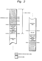
- Fig. 2 shows the structure of areas from the inner periphery side (lead-in side) to the outer periphery side (lead-out side) of the disc.
- the radius position and absolute address (in hexadecimal notation) of each area of the disc are denoted on the left side and the right side of the diagram.
- Emboss pits are recorded in the hatched areas on the innermost periphery side (from radius position 22.6 mm to radius position 24.0 mm) and the outermost periphery side (after radius position 58.00 mm).
- emboss area also referred to as ROM area
- all "00h” data, a reference code for 2 ECC blocks (from absolute address "2F00h"), and 186 blocks of control data (from absolute address "2F200h”) are recorded.
- An ECC block is a data unit that composes an error correction block.
- Control data and reference code are recorded when a master disc is cut.
- the control data and reference code are read-only pit data.
- the control data includes physical management information and so forth of the optical disc.
- Areas other than the emboss area are rewritable areas of which tracks are formed with grooves (namely, groove area).
- a user area is from radius position 24.19 mm to radius position 57.9 mm (from absolute address "31000h” to absolute address "1A0BFh").
- a guard zone In the rewritable areas on the inner periphery side and the outer periphery side of the user area, a guard zone, a disc test zone, a drive test zone, and a DMA (defect management area) are formed.
- the guard zone is formed so as to allow data written to the disc test zone and DMA to synchronize with a write clock.
- the disc test zone is formed so as to check the disc condition.
- the drive test zone is formed so as to check the condition of the recording/reproducing drive.
- DMA1 and DMA2 are formed on the inner periphery side of the disc.
- DAM3 and DAM4 are formed on the outer periphery side of the disc. Same information is recorded in each of the DMA1 to DMA4.
- a detected result of a defect in the recordable area and information of a substitute sector are recorded in the DMA. Since the recording/reproducing operation is performed with reference to the contents of the DMA, a defective area can be skipped.
- the inner periphery areas of the rewritable area (other than the user area) and the emboss area on the innermost periphery side structure a lead-in area as a management area.
- tracks are pre-formed with wobbling grooves.
- the wobbling grooves represent absolute addresses.
- the recording/reproducing apparatus can obtain information of absolute addresses and so forth with reproduced signals of grooves.
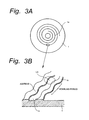
- Figs. 3A and 3B show examples of the structure of grooves of the optical disc 1. As shown in Fig. 3A , a pre-groove is spirally formed from the inner periphery to the outer periphery in a groove area of the optical disc 1.
- the left and right side walls of the pre-groove 1a are wobbled corresponding to address information.
- the pre-groove 1a is wobbled at a predetermined period of a wobbling signal generated corresponding to an address.
- a land 1b is formed between adjacent grooves 1a.
- Data is recorded on a groove 1a.
- the track pitch is the distance between the centers of adjacent grooves 1a.
- the track pitch is for example 0.8 ⁇ m.
- the groove width (the width of the bottom portion of each groove 1a) is for example 0.48 ⁇ m.
- the width of each groove 1a is larger than the width of each land 1b.
- the wobbling amount of each groove 1a is defined as the value of the wobble width WW.
- the wobble width WW is 12.5 nm.
- One track (one turn of the disc) has a plurality of wobbling address frames.
- Each wobbling address frame is divided into eight portions in the direction of the rotation of the disc.
- the eight portions are servo elements (segment 0 to segment 7).
- Each servo segment (hereinafter simply referred to as segment) contains 48-bit information that is mainly an absolute address.
- the wobbling of each segment is composed of 360 waves.
- Fine clock marks are formed on a wobbling groove at equal intervals. With the fine clock marks, a PLL circuit generates a reference clock signal so as to record data. 96 fine clock marks are formed per rotation of the disc. Thus, 12 fine clock marks are formed per segment.
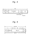
- Fig. 4 shows the structure of each wobbling address frame as segments (segment 0 to segment 7).
- the first four bits are used for a synchronous signal that represents the start of the wobbling address frame.
- the four-bit synchronous pattern is bi-phase data of which four-bit data is composed of eight channel bits.
- the next four bits are used for layer information that represents a layer number of a plurality of record layers or a layer structure of the disc.
- the next 20 bits are used for a track address (track number) as an absolute address.
- the next four bits are used for a segment number.
- the segment number is a value in the range from "0" to "7" corresponding to segment 0 to segment 7. In other words, the segment number represents the circumference position of the disc.
- the next two bits are reserved.
- an error detection code CRC
- fine clock marks are formed in each wobbling address frame at equal intervals.
- ECC Error Correction Code
- One sector is composed of for example 2 kbytes.
- One block is composed of for example 32 kbytes.
- Fig. 5 shows the structure of one sector.
- the data ID contains a track number and a sector number corresponding to an address of the wobbling groove.
- the IED is an error detection parity corresponding to a data ID (for example, CRC).
- the EDC is an error detection parity (for example, CRC) that is used so as to determine whether or not user data that has been error-corrected has an error.
- an ECC block shown in Fig. 6 is composed. Each sector is composed of 2064 bytes (172 bytes x 12).
- 16 sectors each of which is composed of 172 bytes x 12
- the user data of 192 x 172 bytes is encoded with a product code.
- data of each line (172 bytes) is encoded with an inner code (for example, Reed Solomon code).
- an inner code parity of 10 bytes (PI) is generated.
- data of each column (192 bytes) is encoded with an outer code (for example, Reed Solomon code).
- an outer code parity of 16 bytes (PO) is generated.
- a frame synchronous signal (FS) of two byes is added.
- data of one frame is composed of a total of 93 bytes. Consequently, one block is composed of 221 (rows) x 93 x 2 bytes.
- one block (record/reproduction data unit) is composed of 442 frames.
- one block is composed of 16 sectors.
- One sector is composed of 26 frames.
- a linking section is formed between two adjacent blocks. The linking section functions as an area for allowing data that is recorded or reproduced to synchronize with a clock signal.
- the present invention relates to a finalizing process necessary for allowing a ROM drive (for example, a DVD-ROM drive) to reproduce data from an optical disc (for example, a DVD+RW disc).
- the data has been recorded on the optical disc by the above-described drive.
- Fig. 9 shows the concept of the finalizing process according to the present invention.
- data is recorded as blocks in a user area of a rewritable area in which a wobbling groove is formed.
- the DVD-ROM drive accesses the DVD+RW disc and reads data therefrom, the DVD-ROM drive repeats a coarse seek operation and a fine seek operation several times and obtains a target track.
- the DVD-ROM drive performs the spindle servo operation and reads the data ID of each sector, if the data ID has not been recorded, the DVD-ROM drive cannot obtain a frame synchronous information as servo information. In this case, the spindle servo becomes out-of-control state.
- the DVD-ROM drive cannot obtain position information.
- the DVD-ROM drive should always seek a recorded data area.
- the finalization data contains servo information (frame synchronous signal) and position information (ID).
- Fig. 9 shows an example of the state of which as the result of the finalizing process, finalization data is recorded before and after a recorded area of a user area, a rewritable area (test zone, DMA, and so forth) of a lead-in area, and a rewritable area (DMA) of a lead-out area.
- the data amount of finalization data that is recorded is equivalent to the width of several hundred tracks although it depends on the seek accuracy of the drive, the amount of eccentricity of the disc, and so forth.
- a bit map table that has bits that correspond to all blocks of the rewritable area and that represent whether the relevant blocks are recorded blocks or non-recorded blocks is created.
- a recorded block and a non-recorded block are denoted by "1" and "0", respectively.
- WBBM Write Block Bit Map
- the CPU 21 receives information corresponding to a write command from the controller 5. Under the control of the CPU 21, a WBBM is formed in the RAM 23. At a predetermined timing (that will be described later), the CPU 21 reads the WBBM from the RAM 23. The controller 5 records the WBBM to a predetermined area of the lead-in area of the optical disc 1 as with the user data. When the user issues to the host processor 10 (or the disc drive) a command for executing the finalizing process that causes, the command is sent to the CPU 21. Thus, the CPU 21 causes the disc drive to write a predetermined amount of finalization data before and after each recorded block corresponding to the latest WBBM.
- the WBBM is placed in the lead-in area along with a test zone, a DMA, and so forth.
- the WBBM can be placed in the range from 30000h to 31000h of the lead-in area.
- Guard zones are preferably placed before and after the WBBM.
- the finalizing process can be performed with one WBBM.
- WBBM-1 to WBBM-N it is very effective to provide a plurality of WBBMs (WBBM-1 to WBBM-N). Since the number of times of the write operation is limited in phase change type disc mediums (around 100,000 times), if the write operation is repeatedly performed in the same area, the life of the medium is shortened.
- one block is composed of 16 sectors (32 kbytes). Since one DVD+RW disc has a storage capacity of around 3 Gbytes, the disc has 90,000 to 100,000 blocks. When each block is correlated with one bit, a bit map of around 12 kbytes is required. By adding management information to the bit map, one WBBM is structured. When a WBBM is recorded on the disc, as with user data, an encoding process with a product code and a frame structuring process are performed. In other words, one ECC block is composed of one WBBM.
- a WBBM identifier in one WBBM, a WBBM identifier, a ring number, an update counter, and zone information are added to bit map data.
- the bit map is composed of bytes.
- the upper right corner of the bit map represents a bit corresponding to a block of which the ECC block number is 1.
- the ECC block number increases in the left direction of each byte.
- the ECC block number increases in the lower direction of the bit map.
- the left portion of Fig. 11 shows an enlarged view of the N-th byte.
- the N-th byte includes bits whose ECC block numbers are 8N to 8N+7.
- a bit whose value is "0" represents that an ECC block corresponding thereto is a non-recorded block.
- a bit whose value is "1” represents that an ECC block corresponding thereto is a recorded block.
- the management information includes the following items each of which is composed of one byte.
- WBBM identifier A numeric value representing that a relevant ECC block is a WBBM (for example, 0C0Ch).
- Ring number Represents the number of WBBMs that are treated as one set and the order of a particular WBBM in the set.
- Update counter A value that is incremented whenever a WBBM is updated.
- a WBBM with the maximum value of the update counter in the set of WBBMs is determined as the latest WBBM.
- a WBBM with the minimum value of the update counter is updated to the latest WBBM.
- Zone information When the finalizing process is performed, it is not effective to check all bits. To solve such a problem, all the rewritable area is divided into a plurality of zones. When data has been written to all blocks of each zone, a flag that represents that data has been recorded to all blocks is set. Once the flag is set, the finalizing process is not performed for the zone.
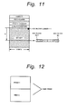
- a plurality of WBBMs with the same content may be written. In this case, whenever a WBBM is updated, all the WBBMs are rewritten.
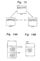
- Fig. 13 shows an example of the ring structure of a plurality of WBBMs (WBBM-1, WBBM-2, ..., and WBBM-N).
- the update counter of each WBBM is initialized to for example "0".
- the WBBM-1 is updated, the value of only the update counter thereof becomes "1".
- the WBBM-2 is updated, the value of only the update counter thereof becomes "2".
- the WBBM-3 is updated, the value of only the update counter thereof becomes "3".
- a WBBM with the minimum value of the update counter is updated. If the values of the update counters of two WBBMs are the same, a WBBM with a lower WBBM number is updated.
- a WBBM with the maximum value of the update counter is determined as the latest WBBM.
- the WBBM is effective information.
- the ECC block is checked before finalization data is written to an ECC block that is determined as an non-recorded block corresponding to the WBBM. Even if the bit corresponding to the ECC block is incorrect, since the finalization data is written, recorded data is not destroyed.
- later WBBMs remain.
- a WBBM with the maximum value of the update counter is defined as the latest WBBM, when the drive spins up and reads a WBBM, it can determine the latest WBBM.
- the medium can be suppressed from deteriorating.
- a method for creating a plurality of WBBMs with the same content can be used (redundant write operation (see Fig. 12 )).
- This method is the simplest countermeasures against a power failure.
- the values of all the update counters should be the same. If the counter value of a particular WBBM is different from the counter values of the other WBBMs, it can be supposed that while a WBBM was being updated, a power failure took place. In this case, a WBBM with a larger value of the update counter is the latest WBBM.
- the ring structure and the redundant write operation can be used together.
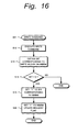
- a WBBM user data map
- conventional WBBM WBBM
- a bit "1" is set to a block to which user data is written.
- a bit corresponding to a block to which finalization data is written is still "0".
- a DVD+RW drive can write data to the DVD+RW disc.
- finalization data should be written to the DVD+RW disc. Since a conventional WBBM is composed of a bit map of user data and a bit map of finalization data (namely, the WBBM represents whether recorded blocks), the user data and the finalization data cannot be distinguished with the WBBM. As a result, finalization data is redundantly written. On the other hand, with both a user WBBM and a conventional WBBM, finalization can be prevented from being redundantly written.
- a portion corresponding to each block on the bit map may be composed of two bits so as to distinguish a record block of user data and a record block of finalization data as shown in Fig. 14B .
- a WBBM is written to a predetermined area of the lead-in area of the DVD+RW disc.
- a blank DVD+RW disc is formatted, if the certificating process is not performed, all the user area becomes non-recorded state. On the other hand, if the certificating process is performed, all the user area becomes recorded state.
- the DVD+RW disc is reformatted, since recorded data resides in the user area, the existing WBBM is used.
- a WBBM is read to a memory (RAM 23 shown in Fig. 1 ) of the drive.
- Fig. 15 is a flow chart showing a process of the CPU 21 performed when a medium is loaded to the drive.
- the medium is loaded to the drive.
- the drive spins up and reproduces a DMA and a WBBM in the lead-in area.
- the drive reads the first WBBM (at step S3) and checks the ring number (management information) of the WBBM (at step S4).
- the drive When the WBBM is ring-structured, since there are a plurality of WBBMs, the drive reads all WBBMs in the RAM 23 and reads values of update counters thereof (at step S5). The drive compares the values of the update counters of all the WBBMs and leaves a WBBM with the maximum value of the update counter in the RAM 23 (at step S6). When the certificating process has been completed or data has been written to all the user area, it is not necessary to leave the WBBM in the RAM 23 or update the WBBM. This determination is performed by the CPU 21 of the drive. A flag is controlled corresponding to the determined result.
- the drive obtains a bit of the WBBM in the RAM 23 corresponding to the block on the bit map (at step S13), and determines whether or not the bit is "0" (at step S14).
- the bit When the bit is "1", it represent that the block is a recorded block. Since it is not necessary to update the bit, the process is completed. In contrast, when the bit is "0", the bit corresponding to the block on the WBBM stored in the RAM 23 is set to "1" (at step S15). In addition, a flag that represents that the WBBM stored in the RAM 23 has been updated is set (this flag is referred to as WBBM update request flag). In this case, the flag is set to "1". At a predetermined timing (in an eject state of the optical disc 1, in a flash cache process, or in a background state), the WBBM of the optical disc 1 is updated. After the WBBM has been updated, the WBBM update request flag is cleared. In the flag cache process, whenever a write command is received, data is temporarily stored in the write cache. Thus, a predetermined number of times of the write command can be executed at a time.
- the background state is a nonbusy state of the CPU of the drive.
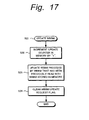
- Fig. 17 is a flow chart showing a process of the CPU 21 when WBBMs are updated. This process is executed at a predetermined timing. In this example, it is assumed that WBBMs are ring-structured.
- the WBBM update request flag is "1”
- a WBBM is updated (at step S21).
- the update counter of the WBBM stored in the RAM 23 is incremented by "1" (at step S22).
- a WBBM preceded by a WBBM that has been previously read is updated with the WBBM stored in the RAM 23.
- a ring number corresponding to a WBBM with the minimum value of the update counter is set.
- a WBBM with the minimum value of the update counter is replaced with the latest WBBM stored in the RAM 23. Since the updating process is completed, the WBBM update request flag is cleared at step S24.
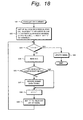
- the user issues a command that causes the drive to execute a finalizing process.
- a finalizing process of the CPU 21 performed by the drive will be described.
- step S31 when the drive receives the finalization command from the host processor 10, a WBBM on the optical disc 1 is replaced with a WBBM stored in the RAM 23.
- the WBBM stored in the RAM 23 is the latest WBBM.
- the latest WBBM may be read from the optical disc 1.
- the listed blocks are denoted by B(0), B(1), B(2), ... and B(N-1).
- the initial value of the variable I is (0).
- step S33 it is determined whether or not the variable I is N.
- the updating process for the WBBM is preformed (at step S34) as described above (see Fig. 17 ).
- step S36 it is determined whether or not data has been read.
- the finalization data is not recorded.
- the finalization data (dummy data) is recorded to the non-recorded block B(I) (at step S37).
- the variable I is incremented.
- the bit corresponding to the recorded block on the WBBM is set to "1".
- the reading operation for verifying an non-recorded block, the recording operation of the finalization data for a verified non-recorded block, the incrementing operation for the variable I, and the process for setting the bit corresponding to the block on the WBBM to "1" are performed for all non-recorded blocks that have been listed up. Thereafter, at step S34, the bit corresponding to a block that has been determined as a recorded block on the WBBM is set to "1".
- the WBBM stored in the RAM 23 is written to the optical disc 1.
- a plurality of blocks that have been listed up are processed one after the other.
- all blocks that have been listed up may be read and determined whether or not they are recorded blocks.
- finalization data may be written to all non-recorded blocks. In this case, the process can be effectively performed and thereby preferably implemented.
- a WBBM is used to effectively perform the finalizing process.
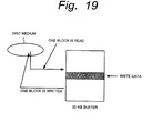
- the WBBM can be used to effectively perform the read modified write operation.
- a DVD-RW disc is accessed for data of 2 kbytes (one sector) at a time by the host processor.
- the buffer memory of the drive is accessed.
- the disc is accessed for data of 32 kbytes of a ECC block at a time by the drive.
- the drive receives a read command for data of 2 kbytes, it reads a block (32 kbytes) including the sector and sends the data of 2 kbytes to the host. In this case, the drive discards the remaining data of 30 kbytes.
- the write operation is more complicated than the read operation.
- the drive when the drive writes data of 2 kbytes to a particular block of the disc, if data has been recorded in the block, the drive should read the block, replace data of 2 kbytes of the relevant sector with write data received from the host processor, and then write data of 32 kbytes to the original block.
- This process is referred to as read modified write operation.
- the drive to write data of 2 kbytes to the disc, the drive reads data of 32 kbytes from the disc and then writes data of 32 kbytes thereto.
- the drive temporarily stores write data in a buffer memory (the buffer memory 6 shown in Fig. 1 ) and completes the write command. This operation is referred to as write cache operation.
- the host computer tends to write successive sectors.
- data of one block may take place.
- the drive only performs the write operation for data of 32 kbytes without the read operation.
- the drive can write a plurality of blocks at a time.
- the drive may write data of 2 kbytes at a time.
- the drive when the drive writes long data, it should perform the read modified write operation at the beginning and the end of the data.
- the block When the drive performs the read modified write operation for a particular block, the block may be a non-recorded block. Generally, when the drive cannot read a block, it determines that the block is a non-recorded block corresponding to information such as a signal level. When the block is a non-recorded block, the drive places all "0" data in the block except for write data received from the host processor. In this case, when the drive can determine that the block is a non-recorded block, it can perform the write operation without the read operation. In other words, the performance can be improved two times. To improve the efficiency of the read modified write operation, a WBBM can be used.
- the CPU 21 when the CPU 21 receives a write command for the area, it can immediately perform the write operation without the read modified write operation.
- the host processor 10 While the host processor 10 is not accessing the CPU 21, it checks a WBBM in the RAM 23, reads a portion preceded by a recorded area of the optical disc 1, and determines that the portion is a non-recorded portion. This operation may be performed in a relatively narrow range for the next write command.
- the CPU 21 When the CPU 21 receives a write command for the area (or caches the write command), if it has determined that the area is a non-recorded area, it places all "0" data as data in the same block other than the write data and performs the write operation, for example, without the read modified write operation. Alternatively, after the CPU 21 has performed the write operation, it updates the WBBM in the RAM 23. Thus, the drive determines whether or not the next area is a non-recorded area.
- the present invention is not limited to the above-described embodiment. Instead, various modifications are available.
- the present invention can be applied to a rewritable disc-shaped record medium other than the DVD+RW medium and to a WO (Write Once) disc-shaped record medium.
- the present invention can be applied to a disc of which address information is recorded in other than wobbling groove format.
- the servo information may be information for either CAV or CLV.
- finalization data may be recorded before or after a recorded block.
- the drive since a bit map that represents that each block is a recorded block or a non-recorded block is provided, in comparison with a method for analyzing a file system, the drive can execute a finalizing process regardless of a file system for use. In addition, even if the number of directories/files is large, the drive can effectively perform the finalizing process.
- the drive in comparison with a method for reading all blocks and determining whether they are recorded blocks or non-recorded blocks, the drive can quickly perform the finalizing process.
- the user is not requested to perform the certifying process. Since the period necessary for the finalizing process is much shorter than the period necessary for the certifying process, the efficiency is very high for the user.
Abstract
Description
- The present invention relates to a recording apparatus for use with an optical disc or the like, a recording method thereof, and a disc-shaped recording medium.
- Disc-shaped record mediums (for example, DVDs) can be categorized as rewritable mediums (DVD+RW) and read-only mediums (DVD-ROM) depending on their characteristics. Since their physical formats are similar, it is preferable to allow a DVD-ROM drive to reproduce data from a DVD+RW disc. There are difference between the DVD+RW drive and the DVD-ROM drive in a spindle servo signal and a method for obtaining a position signal (address) of a medium. The DVD+RW disc has a wobbling groove. The DVD+RW drive obtains a position signal from a reproduced signal of the wobbling groove. In contrast, the DVD-ROM disc does not have such a wobbling groove. The DVD-ROM drive obtains a position signal from a frame synchronous signal and an address signal reproduced from the DVD-ROM disc.
- To allow the DVD-ROM drive to reproduce data from the DVD-RW disc, a frame synchronous signal and a position signal are placed in data of the DVD+RW disc. However, since the DVD+RW disc has a non-recorded portion before or after recorded data, it is difficult for the DVD-ROM drive to reproduce data from the DVD+RW disc. In reality, since the DVD-ROM drive cannot reproduce the frame synchronous signal from the DVD+RW disc, the DVD-ROM cannot stably operate the spindle servo and perform the seek operation for reading a desired sector from the DVD+RW disc.
- The seek operation is performed in a combination of a coarse seek operation and a fine seek operation. In the coarse servo operation, many tracks are jumped at a time. On the other hand, in the fine servo operation, a desired sector is acquired in the vicinity of a target position. Due to the eccentricity of the disc, when the seek operation is performed in the fine servo operation, a deviation of several ten tracks to several hundred tracks normally takes place. If the jumped position is a non-recorded area, the target track cannot be acquired. Thus, when the seek operation is performed, data containing a frame synchronous signal and a position signal should have been recorded in the vicinity of the target sector.
- Thus, to allow the DVD-ROM drive to reproduce data from the DVD+RW disc, dummy data should have been recorded before or after recorded data on the DVD+RW. To do that, a process referred to as finalizing process is performed. The finalizing process can be performed in the following two methods.
- As the first method, a file system is analyzed. Generally, a file system has a space bit map for allocating a user area. A UDF system that is often used for DVD discs has a space bit map and information that represents whether or not each entry of each file has been recorded. Thus, when the file system is analyzed, a position of user data (namely, a position to which dummy data should be written) can be obtained. This method is performed by an application program of a host computer.
- As the second method, a blank area is detected. In this method, all blocks of the DVD+RW disc are read. When a block can be read, it is treated as a recorded block. On the other hand, when a block cannot be read, the hardware of the drive determines whether an RF signal is absent (namely, data has been recorded) or data that has been recorded cannot be reproduced. When the RF signal cannot be obtained, since data has not been recorded, dummy data is recorded. Even if the RF signal is obtained, when data cannot be read, the drive determines whether the relevant block is unchanged or dummy data is overwritten depending on the amount of an ECC error or the like.
- The first method (for analyzing a file system for use) can be effectively performed as long as the number of directories/files is small. However, when the number of directories/files is as large as several thousands, it takes a long time to perform the process. Thus, this method is not effective. In the file system other than the UDF system, this method cannot be used because available information is limited to allocation information. In other words, depending on a file system for use, the feasibility of this method is restricted. On the other hand, the second method (for detecting a blank area) can be used regardless of a file system for use. However, since all blocks of the disc should be read, it takes a long time to perform the process.
- Other than the above-described two methods, when a disc is formed, a certificating process may be required. In the certificating process, a certification pattern is recorded on the entire disc. By reproducing the data, it is determined whether or not there is a defect on the disc. Thus, when the certification pattern is recorded on the entire surface, since non-recorded areas are absent, the finalizing process is not required. However, since the storage capacity of the DVD+RW disc is large, it takes around one hour to perform the certificating process. Thus, since this method is not effective, it is improper to require the user to perform the certificating process.
- It is therefore an object of the invention to provide a recording medium, a recording apparatus, a recording method, a reproducing apparatus, a reproducing method and computer software that allow the finalizing process to be quickly performed regardless of a file system for use.
- In an
embodiment 1 of the present invention, a recording apparatus for use with a disc- shaped record medium having a user data area and a management area, comprises recording means for recording at least one conventional bit map that represent whether or not each data unit for recording/reproducing has been recorded; and processing means for recording the bit map to the management area of the disc-shaped record medium (1), and referencing the bit map and adding a predetermined amount of data that contains at least one of servo information and position information to a non-recorded area in the vicinity of recorded data so as to allow a reproducing apparatus that reproduces data from a read-only disc-shaped medium and obtains at least one of the servo information and the position information from a reproduced signal to reproduce data from a rewritable disc-shaped record medium. - In an
embodiment 2 as set forth in theembodiment 1, the management area has a plurality of conventional bit maps and an update counter each of the bit maps has a value of an update counter that represents the number of update times of each of bit maps, and the processing means rewriting the plurality of bit maps successively and rewriting the value of the update counters of the bit map rewritten corresponding to what represents the number of update times. - In an
embodiment 3 as set forth inembodiment - In an
embodiment 4 as set forth inembodiment - In an
embodiment 5 as set forth in anyone ofembodiments 1 to 4, the conventional bit map comprises a user data bit map, the user data bit map has a first bit and a second bit for each record/reproduction data unit, and one of the first bit and the second bit represents whether or not each record/reproduction data unit has been recorded and the other of the first bit and the second bit represents whether or not the user data has been recorded for each record/reproduction data unit. - In an
embodiment 6 as set forth in anyone ofembodiments 1 to 5, the recording means stores bit map data corresponding to the conventional bit map, the processing means performs an updating process which rewrites the bit map data whenever a write operation is performed and which records the bit map data to the management area at a predetermined timing of which a write operation and a read operation are not performed. - In an
embodiment 7 as set forth inembodiment 6, the predetermined timing is an eject state of the disc-shaped record medium. - In an
embodiment 8 as set forth inembodiment 6, the predetermined timing is a flush cache state. - In an
embodiment 9 as set forth inembodiment 6, the predetermined timing is a background state in which a command is not received from the outside of the recording apparatus. - In an
embodiment 10 as set forth in anyone of the preceding embodiments, the processing means references the bit map, lists up a non-recorded area in the vicinity of recorded data, and records a predetermined amount of data that contains at least one of the servo information and the position information to the verified non-recorded area after verifying the non-recorded state of the non-recorded area by reproducing the listed non-recorded area.
In anembodiment 11 as set forth in anyone of the preceding embodiments, the processing means verifies whether or not a partial area preceded by a recorded area is a non-recorded area before performing a write operation by referencing the bit map. - In an
embodiment 12 as set forth inembodiment 11, the processing means performs a write operation for the verified non-recorded area without performing a read operation of a read modified write operation. - In an
embodiment 13, a recording method for use with a disc-shaped record medium 1 having a user data area and a management area, comprising the steps of: creating a bit map composed of bits that represent whether or not each record/reproduction data unit has been recorded; recording the bit map to the management area of the disc-shaped record medium; and referencing the bit map and adding a predetermined amount of data that contains at least one of servo information and position information to a non-recorded area in the vicinity of recorded data so as to allow a reproducing apparatus that reproduces data from a read-only disc-shaped medium and obtains at least one of the servo information and the position information from a reproduced signal to reproduce data from a rewritable disc-shaped record medium. - In an
embodiment 14, a disc-shaped record medium having a first rewritable area for recording user data and a second rewritable area for recording management data, wherein at least one of servo information and position information is pre-recorded as wobbling information in a wobbling groove, and wherein the second rewritable area has a bit map that represents whether or not each data unit for recording/reproducing for the first rewritable area has been recorded. - In an
embodiment 15 as set forth inembodiment 14, dummy data is added in the vicinity of recorded data in the first rewritable area and the second rewritable area. - In an
embodiment 16 as set forth inembodiment 15, the dummy data has servo information and position information which are necessary for a reproducing apparatus that reproduces data from a read-only disc-shaped medium. - In so far as the embodiments of the invention described above are implemented, at least in part, using a software-controlled data apparatus, it will be appreciated that a computer program providing such software control and a transmission, storage or other medium by which such a computer program is provided are envisaged as aspects of the present invention.
- The above, and other, objects, features and advantage of the present invention will become readily apparent from the following detailed description thereof which is to be read in connection with the accompanying drawings.
- Embodiments of the invention are now described with reference to the enclosed drawings, throughout which like parts are referred to be like references.
-
-
Fig. 1 is block diagram showing the structure of each area of a drive according to an embodiment of the invention; -
Fig. 2 is a schematic diagram showing the structure of each area of a disc-shaped record medium according to the invention; -
Figs. 3A and 3B are schematic diagrams showing a wobbling groove of the disc-shaped record medium according to the invention; -
Fig. 4 is a schematic diagram for explaining the frame structure of the wobbling groove of the disc-shaped record medium according to the invention; -
Fig. 5 is a schematic diagram showing a sector format of the disc-shaped record medium according to the invention; -
Fig. 6 is a schematic diagram showing a 32 kbyte format of the disc-shaped record medium according to the invention; -
Fig. 7 is a schematic diagram showing an interleaved state of an outer code in the 32 kbyte format of the disc-shaped record medium according to the invention; -
Fig. 8 is a schematic diagram showing the block structure of the disc-shaped record medium according to the invention; -
Fig. 9 is a schematic diagram for explaining a finalizing process; -
Fig. 10 is a schematic diagram for explaining record positions of WBBMs; -
Fig. 11 is a schematic diagram for explaining the data structure of a WBBM; -
Fig. 12 is a schematic diagram for explaining a redundant write operation of WBBMs; -
Fig. 13 is a schematic diagram for explaining a ring structure of WBBMs; -
Figs. 14A and 14B are schematic diagrams for explaining a WBBM having a bit map for user data; -
Fig. 15 is a flow chart for explaining a process performed when a medium is loaded to a drive; -
Fig. 16 is a flow chart for explaining a process performed when a write command is executed; -
Fig. 17 is a flow chart for explaining a process for updating a WBBM; -
Fig. 18 is a flow chart for explaining the finalizing process; -
Fig. 19 is a schematic diagram for explaining a read modified write operation. - Next, with reference to the accompanying drawings, an embodiment of the present invention will be described. In the embodiment, a phase change type disc is used as a rewritable optical disc. In reality, two discs whose diameters are 120 mm and whose thicknesses are 0.6 mm are adhered to form a rewritable optical disc. In addition, the rewritable optical disc has a wobbling groove. As will be described later, the wobbling groove is wobbled with a signal of which an address (a position signal) is wobbled. A clock signal for signal processing and an absolute address on the disc can be extracted from the reproduced signal of the wobbling groove.
- In addition, the disc is rotated at CAV (Constant Angular Velocity). Data is recorded in a groove. In other words, a groove system is used. Data is recorded at CLD (Constant Linear Density) on the disc. The linear density is 0.35 µm/bit. A predetermined range of linear densities is designated. A rewritable area of the disc is divided into many zones. In each zone, a linear density is defined. This type of disc is referred to as DVD+RW disc. However, it should be noted that the present invention is not limited to a DVD+RW disc. In other words, the present invention can be applied to optical discs such as a groove/land record type disc and a magnetic optical (MO) record disc.
- Next, with reference to
Fig. 1 , the structure of a disc drive for use with a rewritable optical disc such as a DVD+RW disc will be described in brief. InFig. 1 ,reference numeral 1 is a phase change type optical disc. Theoptical disc 1 is rotated at CAV by aspindle motor 2. Anoptical pickup 3 is disposed so as to record data on theoptical disc 1 and to reproduce data therefrom. - Data of an
external host processor 10 is supplied to the disc drive through aninterface 4. Acontroller 5 is connected to theinterface 4. Abuffer memory 6 is connected to thecontroller 5. Thebuffer memory 6 stores write data or read data. Write data is supplied from thecontroller 5 to anencoder 7. Theencoder 7 converts the write data into sector-structured data, encodes each ECC block that is composed of 16 sectors with an error correction code, and adds a frame synchronous signal and a linking section. - The frame-structured data is supplied to a
recording system 8. Therecording system 8 performs a digital modulating process and so forth. Therecording system 8 supplies record data to alaser drive 9. Thelaser drive 9 generates a drive waveform corresponding to a predetermined level necessary for recording data to theoptical disc 1. Output data of thelaser drive 9 is supplied to theoptical pickup 3. - The
optical pickup 3 reproduces data on theoptical disc 1. The reproduced data is detected by a photo detector. The detected signal is supplied to an amplifyingcircuit 11. An output signal of the amplifyingcircuit 11 is supplied to a reproducingsystem 12 and aservo system 14. The amplifyingcircuit 11 calculates the detected signal of the photo detector and generates an RF signal, a tracking error signal, and a focus error signal. The RF signal is supplied to a reproducingsystem 12. The tracking error signal and the focus error signal are supplied to aservo system 14. - The reproducing
system 12 performs a digital demodulating process. In addition, the reproducingsystem 12 processes a reproduced signal of a wobbling groove and demodulates an address. The separated frame synchronous signal and the address are supplied to theservo system 14. Theservo system 14 performs a tracking servo operation and a focus servo operation for theoptical pickup 3. In addition, theservo system 14 performs a spindle servo operation and a sled servo operation for theoptical pickup 3. In the sled servo operation, theservo system 14 moves theoptical pickup 3 in the radius direction of the disc. - The reproduced data of the reproducing
system 12 is supplied to adecoder 13. Thedecoder 13 decodes an error correction code (namely, corrects an error of the reproduced data), disassembles the reproduced data into sector-structured data, and performs another process. The reproduced data of thedecoder 13 is supplied to thecontroller 5. Thereafter, the reproduced data is stored in thebuffer memory 6. When a read command is received from thehost processor 10, read data is sent to thehost processor 10 through theinterface 4. - To drive the entire operation of the disc drive, a
CPU 21 is disposed. A RAM 23 and aROM 24 are connected to theCPU 21 through abus 22. TheROM 24 stores a program. A reproduced address of the reproducingsystem 12 is supplied to thebus 22. In addition, thecontroller 5 is connected to thebus 22. - Next, an example of the rewritable
optical disc 1 will be described.Fig. 2 shows the structure of areas from the inner periphery side (lead-in side) to the outer periphery side (lead-out side) of the disc. InFig. 2 , the radius position and absolute address (in hexadecimal notation) of each area of the disc are denoted on the left side and the right side of the diagram. - Emboss pits are recorded in the hatched areas on the innermost periphery side (from radius position 22.6 mm to radius position 24.0 mm) and the outermost periphery side (after radius position 58.00 mm). In the emboss area (also referred to as ROM area), all "00h" data, a reference code for 2 ECC blocks (from absolute address "2F00h"), and 186 blocks of control data (from absolute address "2F200h") are recorded. An ECC block is a data unit that composes an error correction block. An error correction code parity is added to data of every 32 kbytes (= 2 kbytes x 16).
- Control data and reference code are recorded when a master disc is cut. The control data and reference code are read-only pit data. The control data includes physical management information and so forth of the optical disc.
- Areas other than the emboss area (namely, areas from radius position 24.0 mm to radius position 58.0 mm) are rewritable areas of which tracks are formed with grooves (namely, groove area). In the groove area, a user area is from radius position 24.19 mm to radius position 57.9 mm (from absolute address "31000h" to absolute address "1A0BFh").
- In the rewritable areas on the inner periphery side and the outer periphery side of the user area, a guard zone, a disc test zone, a drive test zone, and a DMA (defect management area) are formed. The guard zone is formed so as to allow data written to the disc test zone and DMA to synchronize with a write clock. The disc test zone is formed so as to check the disc condition. The drive test zone is formed so as to check the condition of the recording/reproducing drive.
- DMA1 and DMA2 are formed on the inner periphery side of the disc. DAM3 and DAM4 are formed on the outer periphery side of the disc. Same information is recorded in each of the DMA1 to DMA4. A detected result of a defect in the recordable area and information of a substitute sector are recorded in the DMA. Since the recording/reproducing operation is performed with reference to the contents of the DMA, a defective area can be skipped. The inner periphery areas of the rewritable area (other than the user area) and the emboss area on the innermost periphery side structure a lead-in area as a management area.
- In the groove area other than the emboss area on the
optical disc 1, tracks are pre-formed with wobbling grooves. The wobbling grooves represent absolute addresses. Thus, the recording/reproducing apparatus can obtain information of absolute addresses and so forth with reproduced signals of grooves. -
Figs. 3A and 3B show examples of the structure of grooves of theoptical disc 1. As shown inFig. 3A , a pre-groove is spirally formed from the inner periphery to the outer periphery in a groove area of theoptical disc 1. - As shown in
Fig. 3B , the left and right side walls of the pre-groove 1a are wobbled corresponding to address information. In other words, the pre-groove 1a is wobbled at a predetermined period of a wobbling signal generated corresponding to an address. Aland 1b is formed betweenadjacent grooves 1a. Data is recorded on agroove 1a. Thus, the track pitch is the distance between the centers ofadjacent grooves 1a. The track pitch is for example 0.8 µm. The groove width (the width of the bottom portion of eachgroove 1a) is for example 0.48 µm. The width of eachgroove 1a is larger than the width of eachland 1b. - The wobbling amount of each
groove 1a is defined as the value of the wobble width WW. In this example, the wobble width WW is 12.5 nm. On each groove, the wobble amount instantaneously increases at predetermined intervals. A portion of which the wobble amount instantaneously increases is referred to as fine clock mark. In this portion, the wobble amplitude is for example 25 to 30 nm. - One track (one turn of the disc) has a plurality of wobbling address frames. Each wobbling address frame is divided into eight portions in the direction of the rotation of the disc. The eight portions are servo elements (
segment 0 to segment 7). Each servo segment (hereinafter simply referred to as segment) contains 48-bit information that is mainly an absolute address. The wobbling of each segment is composed of 360 waves. - Fine clock marks are formed on a wobbling groove at equal intervals. With the fine clock marks, a PLL circuit generates a reference clock signal so as to record data. 96 fine clock marks are formed per rotation of the disc. Thus, 12 fine clock marks are formed per segment.
-
Fig. 4 shows the structure of each wobbling address frame as segments (segment 0 to segment 7). In each (48-bit) wobbling address frame, the first four bits are used for a synchronous signal that represents the start of the wobbling address frame. The four-bit synchronous pattern is bi-phase data of which four-bit data is composed of eight channel bits. The next four bits are used for layer information that represents a layer number of a plurality of record layers or a layer structure of the disc. - The next 20 bits are used for a track address (track number) as an absolute address. The next four bits are used for a segment number. The segment number is a value in the range from "0" to "7" corresponding to
segment 0 tosegment 7. In other words, the segment number represents the circumference position of the disc. The next two bits are reserved. As the last 14 bits of the wobbling address frame, an error detection code (CRC) is added. As was described above, fine clock marks are formed in each wobbling address frame at equal intervals. - Data is read/written as each ECC block. One sector is composed of for example 2 kbytes. One block is composed of for example 32 kbytes.
Fig. 5 shows the structure of one sector. One sector is composed of data ID (four bytes), IED (two bytes), reserved area (six bytes), user data (2048 bytes = 2 kbytes), and EDC (four bytes). In other words, one sector is composed of a total of 2064 bytes. - The data ID contains a track number and a sector number corresponding to an address of the wobbling groove. The IED is an error detection parity corresponding to a data ID (for example, CRC). The EDC is an error detection parity (for example, CRC) that is used so as to determine whether or not user data that has been error-corrected has an error.
- With 16 sectors (each of which has the structure shown in
Fig. 5 ), an ECC block shown inFig. 6 is composed. Each sector is composed of 2064 bytes (172 bytes x 12). When 16 sectors (each of which is composed of 172 bytes x 12) is vertically arranged as shown inFig. 6 , a data array of (172 bytes x 192 (= 12 x 16)) is formed. The user data of 192 x 172 bytes is encoded with a product code. In other words, data of each line (172 bytes) is encoded with an inner code (for example, Reed Solomon code). Thus, an inner code parity of 10 bytes (PI) is generated. In addition, data of each column (192 bytes) is encoded with an outer code (for example, Reed Solomon code). Thus, an outer code parity of 16 bytes (PO) is generated. - Moreover, in block segmented data of 182 bytes x 208 (= (172 + 10) x (192 + 16)), the outer code parity (PO) of 182 bytes x 16 is divided into data of 16 x (182 bytes x 1). As shown in
Fig. 7 , the divided portions of the outer code parity are interleaved with 16sectors 0 to 15 (each of which is composed of (182 bytes x 12)). In other words, each of the divided portions of the outer parity is placed at the end of each of the sectors. After the encoding process with the product code is performed, data of 13 (= 12 + 1) x 182 bytes is treated as data of one sector. - When data of 182 bytes x 208 shown in
Fig. 7 is recorded on the disc, the data is recorded in the structure of a transmission frame shown inFig. 8 . In other words, 182 bytes of each ligne is divided into two portions as 208 (rows) x 2 (frames). At the beginning of each portion of 208 x 2 frames, a linking section (data of link area) of 13 (rows) x 2 (frames) is added. More accurately, a part of data of linking sections for 26 frames is recorded at the end of the preceding block. The rest is recorded at the beginning of the current block. - At the beginning of frame data of 91 bytes, a frame synchronous signal (FS) of two byes is added. Thus, as shown in
Fig. 8 , data of one frame is composed of a total of 93 bytes. Consequently, one block is composed of 221 (rows) x 93 x 2 bytes. In other words, one block (record/reproduction data unit) is composed of 442 frames. The size of the real data portion excluding the overhead portion becomes 32 kbytes (= 2048 x 16/1024 kbytes). - As described above, according to the embodiment, one block is composed of 16 sectors. One sector is composed of 26 frames. A linking section is formed between two adjacent blocks. The linking section functions as an area for allowing data that is recorded or reproduced to synchronize with a clock signal.
- The present invention relates to a finalizing process necessary for allowing a ROM drive (for example, a DVD-ROM drive) to reproduce data from an optical disc (for example, a DVD+RW disc). The data has been recorded on the optical disc by the above-described drive.
Fig. 9 shows the concept of the finalizing process according to the present invention. InFig. 9 , data is recorded as blocks in a user area of a rewritable area in which a wobbling groove is formed. - When the DVD-ROM drive accesses the DVD+RW disc and reads data therefrom, the DVD-ROM drive repeats a coarse seek operation and a fine seek operation several times and obtains a target track. When the DVD-ROM drive performs the spindle servo operation and reads the data ID of each sector, if the data ID has not been recorded, the DVD-ROM drive cannot obtain a frame synchronous information as servo information. In this case, the spindle servo becomes out-of-control state. In addition, since the ID data is absent, the DVD-ROM drive cannot obtain position information. Thus, the DVD-ROM drive should always seek a recorded data area. Due to eccentricity or the like of the disc, even if the DVD-ROM drive jumps from the current track to a desired track, the obtained track deviates from the desired track to some extent. Thus, it is necessary to place dummy data (hereinafter referred to as finalization data) in such a range. Although the finalization data has no meaning (for example, all "0" data), the sector structure and the block structure thereof are the same as those of the above-described user data. Thus, the finalization data contains servo information (frame synchronous signal) and position information (ID).
-
Fig. 9 shows an example of the state of which as the result of the finalizing process, finalization data is recorded before and after a recorded area of a user area, a rewritable area (test zone, DMA, and so forth) of a lead-in area, and a rewritable area (DMA) of a lead-out area. The data amount of finalization data that is recorded is equivalent to the width of several hundred tracks although it depends on the seek accuracy of the drive, the amount of eccentricity of the disc, and so forth. - To perform the finalizing process, it is necessary to determine whether each block is a recorded block or non-recorded block. A bit map table that has bits that correspond to all blocks of the rewritable area and that represent whether the relevant blocks are recorded blocks or non-recorded blocks is created. In the bit map table, a recorded block and a non-recorded block are denoted by "1" and "0", respectively. Whenever a write command is executed, the bit corresponding to the relevant block is changed to "1". Thus, information that represents a recorded (written) block can be used. This bit map is referred to as WBBM (Written Block Bit Map).
- In the structure shown in
Fig. 1 , theCPU 21 receives information corresponding to a write command from thecontroller 5. Under the control of theCPU 21, a WBBM is formed in the RAM 23. At a predetermined timing (that will be described later), theCPU 21 reads the WBBM from the RAM 23. Thecontroller 5 records the WBBM to a predetermined area of the lead-in area of theoptical disc 1 as with the user data. When the user issues to the host processor 10 (or the disc drive) a command for executing the finalizing process that causes, the command is sent to theCPU 21. Thus, theCPU 21 causes the disc drive to write a predetermined amount of finalization data before and after each recorded block corresponding to the latest WBBM. - As shown in
Fig. 10 , the WBBM is placed in the lead-in area along with a test zone, a DMA, and so forth. The WBBM can be placed in the range from 30000h to 31000h of the lead-in area. Guard zones are preferably placed before and after the WBBM. Theoretically, the finalizing process can be performed with one WBBM. However, to improve the reliability of the finalizing process and decrease the number of times of the write operation to the same area, it is very effective to provide a plurality of WBBMs (WBBM-1 to WBBM-N). Since the number of times of the write operation is limited in phase change type disc mediums (around 100,000 times), if the write operation is repeatedly performed in the same area, the life of the medium is shortened. - Next, an example of the structure of the WBBM will be described in detail. As described above, one block is composed of 16 sectors (32 kbytes). Since one DVD+RW disc has a storage capacity of around 3 Gbytes, the disc has 90,000 to 100,000 blocks. When each block is correlated with one bit, a bit map of around 12 kbytes is required. By adding management information to the bit map, one WBBM is structured. When a WBBM is recorded on the disc, as with user data, an encoding process with a product code and a frame structuring process are performed. In other words, one ECC block is composed of one WBBM.
- As shown in
Fig. 11 , in one WBBM, a WBBM identifier, a ring number, an update counter, and zone information are added to bit map data. The bit map is composed of bytes. The upper right corner of the bit map represents a bit corresponding to a block of which the ECC block number is 1. The ECC block number increases in the left direction of each byte. In addition, the ECC block number increases in the lower direction of the bit map. The left portion ofFig. 11 shows an enlarged view of the N-th byte. The N-th byte includes bits whose ECC block numbers are 8N to 8N+7. In the N-th byte, a bit whose value is "0" represents that an ECC block corresponding thereto is a non-recorded block. In contrast, a bit whose value is "1" represents that an ECC block corresponding thereto is a recorded block. - The management information includes the following items each of which is composed of one byte.
- WBBM identifier: A numeric value representing that a relevant ECC block is a WBBM (for example, 0C0Ch).
- Ring number: Represents the number of WBBMs that are treated as one set and the order of a particular WBBM in the set.
- Update counter: A value that is incremented whenever a WBBM is updated. A WBBM with the maximum value of the update counter in the set of WBBMs is determined as the latest WBBM. A WBBM with the minimum value of the update counter is updated to the latest WBBM. Thus, a write operation can be prevented from being concentratedly performed to a particular WBBM. Consequently, the disc medium can be prevented from deteriorating. Even if data of the latest WBBM is destroyed, with information of a WBBM having the maximum value of the update counter, the destroyed WBBM can be almost restored.
- Zone information: When the finalizing process is performed, it is not effective to check all bits. To solve such a problem, all the rewritable area is divided into a plurality of zones. When data has been written to all blocks of each zone, a flag that represents that data has been recorded to all blocks is set. Once the flag is set, the finalizing process is not performed for the zone.
- As shown in
Fig. 12 , to improve the reliability of the finalizing process, a plurality of WBBMs with the same content may be written. In this case, whenever a WBBM is updated, all the WBBMs are rewritten. -
Fig. 13 shows an example of the ring structure of a plurality of WBBMs (WBBM-1, WBBM-2, ..., and WBBM-N). The update counter of each WBBM is initialized to for example "0". When the WBBM-1 is updated, the value of only the update counter thereof becomes "1". Next, when the WBBM-2 is updated, the value of only the update counter thereof becomes "2". Next, when the WBBM-3 is updated, the value of only the update counter thereof becomes "3". In such a manner, a WBBM with the minimum value of the update counter is updated. If the values of the update counters of two WBBMs are the same, a WBBM with a lower WBBM number is updated. Thus, a WBBM with the maximum value of the update counter is determined as the latest WBBM. - Even if a WBBM is not the latest WBBM (even if several recorded bits are lost), the WBBM is effective information. In other words, before finalization data is written to an ECC block that is determined as an non-recorded block corresponding to the WBBM, the ECC block is checked. Even if the bit corresponding to the ECC block is incorrect, since the finalization data is written, recorded data is not destroyed. Thus, when a plurality of WBBMs are used and the oldest WBBM is rewritten, later WBBMs remain. In the case that a WBBM with the maximum value of the update counter is defined as the latest WBBM, when the drive spins up and reads a WBBM, it can determine the latest WBBM.
- The advantages of the ring structure of WBBMs are as follows.
- Since the number of times of the write operation to a particular WBBM is decreased to 1 / (the number of rings of WBBMs), the medium can be suppressed from deteriorating.
- Even if a defect such as power failure of the drive takes place during a write operation of a WBBM, since the preceding WBBM resides, it can be used as the latest WBBM.
- A method for creating a plurality of WBBMs with the same content can be used (redundant write operation (see
Fig. 12 )). This method is the simplest countermeasures against a power failure. In this case, the values of all the update counters should be the same. If the counter value of a particular WBBM is different from the counter values of the other WBBMs, it can be supposed that while a WBBM was being updated, a power failure took place. In this case, a WBBM with a larger value of the update counter is the latest WBBM. The ring structure and the redundant write operation can be used together. - Next, with reference to
Figs. 14A and 14B , other examples of a WBBM will be described. In the example shown inFig. 14A , a user data map (referred to as user WBBM) is paired with the above-described WBBM (referred to as conventional WBBM). Since a conventional WBBM only represents whether each block is a recorded block or a non-recorded bloc, it cannot represent whether data of a recorded block is user data or finalization data. In the user WBBM, a bit "1" is set to a block to which user data is written. Thus, a bit corresponding to a block to which finalization data is written is still "0". - With the user WBBM, after a DVD-ROM drive has reproduced data from a DVD+RW disc to which finalization data had been written, a DVD+RW drive can write data to the DVD+RW disc. In this case, to allow the DVD-ROM drive to reproduce data from the DVD+RW disc, finalization data should be written to the DVD+RW disc. Since a conventional WBBM is composed of a bit map of user data and a bit map of finalization data (namely, the WBBM represents whether recorded blocks), the user data and the finalization data cannot be distinguished with the WBBM. As a result, finalization data is redundantly written. On the other hand, with both a user WBBM and a conventional WBBM, finalization can be prevented from being redundantly written.
- Unlike with the structure of which a user WBBM is paired with a conventional WBBM as shown in
Fig. 14A . a portion corresponding to each block on the bit map may be composed of two bits so as to distinguish a record block of user data and a record block of finalization data as shown inFig. 14B . With such a bit map that allows user data and finalization data to be distinguished, the finalizing process can be more effectively performed. - When a DVD+RW disc is formatted, a WBBM is written to a predetermined area of the lead-in area of the DVD+RW disc. When a blank DVD+RW disc is formatted, if the certificating process is not performed, all the user area becomes non-recorded state. On the other hand, if the certificating process is performed, all the user area becomes recorded state. When the DVD+RW disc is reformatted, since recorded data resides in the user area, the existing WBBM is used.
- When a DVD+RW disc is loaded to a drive, a WBBM is read to a memory (RAM 23 shown in
Fig. 1 ) of the drive.Fig. 15 is a flow chart showing a process of theCPU 21 performed when a medium is loaded to the drive. At step S1 shown inFig. 15 , the medium is loaded to the drive. At step S2, the drive spins up and reproduces a DMA and a WBBM in the lead-in area. The drive reads the first WBBM (at step S3) and checks the ring number (management information) of the WBBM (at step S4). When the WBBM is ring-structured, since there are a plurality of WBBMs, the drive reads all WBBMs in the RAM 23 and reads values of update counters thereof (at step S5). The drive compares the values of the update counters of all the WBBMs and leaves a WBBM with the maximum value of the update counter in the RAM 23 (at step S6). When the certificating process has been completed or data has been written to all the user area, it is not necessary to leave the WBBM in the RAM 23 or update the WBBM. This determination is performed by theCPU 21 of the drive. A flag is controlled corresponding to the determined result. - Next, with reference to a flow chart shown in
Fig. 16 , a process of theCPU 21 for rewriting a WBBM stored in the RAM 23 will be described. This process is performed when a write command is executed. For simplicity, it is assumed that there is no user WBBM. When the drive spins up a medium (optical disc 1) and determines that a conventional WBBM thereof should be managed, this process is performed. A write command from thehost processor 10 is received (at step S11). When the execution of the write command is completed at step S12 (namely, it is determined that data has been recorded to all one block), the drive obtains a bit of the WBBM in the RAM 23 corresponding to the block on the bit map (at step S13), and determines whether or not the bit is "0" (at step S14). - When the bit is "1", it represent that the block is a recorded block. Since it is not necessary to update the bit, the process is completed. In contrast, when the bit is "0", the bit corresponding to the block on the WBBM stored in the RAM 23 is set to "1" (at step S15). In addition, a flag that represents that the WBBM stored in the RAM 23 has been updated is set (this flag is referred to as WBBM update request flag). In this case, the flag is set to "1". At a predetermined timing (in an eject state of the
optical disc 1, in a flash cache process, or in a background state), the WBBM of theoptical disc 1 is updated. After the WBBM has been updated, the WBBM update request flag is cleared. In the flag cache process, whenever a write command is received, data is temporarily stored in the write cache. Thus, a predetermined number of times of the write command can be executed at a time. The background state is a nonbusy state of the CPU of the drive. -
Fig. 17 is a flow chart showing a process of theCPU 21 when WBBMs are updated. This process is executed at a predetermined timing. In this example, it is assumed that WBBMs are ring-structured. When the WBBM update request flag is "1", a WBBM is updated (at step S21). The update counter of the WBBM stored in the RAM 23 is incremented by "1" (at step S22). - At step S23, a WBBM preceded by a WBBM that has been previously read is updated with the WBBM stored in the RAM 23. In this process, among some WBBMs of the
optical disc 1, a ring number corresponding to a WBBM with the minimum value of the update counter is set. A WBBM with the minimum value of the update counter is replaced with the latest WBBM stored in the RAM 23. Since the updating process is completed, the WBBM update request flag is cleared at step S24. - To allow a DVD-ROM drive to reproduce data from a DVD+RW medium, the user issues a command that causes the drive to execute a finalizing process.
Next, with reference to a flow chart shown inFig. 18 , the finalizing process of theCPU 21 performed by the drive will be described. At step S31, when the drive receives the finalization command from thehost processor 10, a WBBM on theoptical disc 1 is replaced with a WBBM stored in the RAM 23. Thus, the WBBM stored in the RAM 23 is the latest WBBM.
Alternatively, the latest WBBM may be read from theoptical disc 1. - At step S32, with reference to the WBBM stored in the RAM 23, all non-recorded blocks adjacent to recorded blocks (bit = "1") in a predetermined range (for example, blocks equivalent to 300 tracks) are listed up. The listed blocks are denoted by B(0), B(1), B(2), ... and B(N-1). At step S32, the initial value of the variable I is (0).
- At step S33, it is determined whether or not the variable I is N. When (I = N), since the finalization data has been recorded to all non-recorded blocks, the updating process for the WBBM is preformed (at step S34) as described above (see
Fig. 17 ). - The finalization data is recorded from the block B(0) to the block B(N-1). In this case, it is determined whether or not an area to which finalization data is recorded corresponding to the WBBM is a non-recorded area. Even if it is determined that a particular block is a non-recorded block (bit = 0) corresponding to the WBBM, due to a power failure, the block may be a recorded block. When the block is a recorded block, if the finalization data is overwritten, recorded user data will be destroyed. To prevent such a problem, a read operation is performed for an area to which finalization data is recorded (at step S35).
- At step S36, it is determined whether or not data has been read. When data has been read or it is not necessary to record data, since the block B(I) is a recorded block or a record unnecessary block, the finalization data is not recorded. When data cannot be read, the finalization data (dummy data) is recorded to the non-recorded block B(I) (at step S37). At step S38, the variable I is incremented. At step S39, the bit corresponding to the recorded block on the WBBM is set to "1".
- The reading operation for verifying an non-recorded block, the recording operation of the finalization data for a verified non-recorded block, the incrementing operation for the variable I, and the process for setting the bit corresponding to the block on the WBBM to "1" are performed for all non-recorded blocks that have been listed up. Thereafter, at step S34, the bit corresponding to a block that has been determined as a recorded block on the WBBM is set to "1". The WBBM stored in the RAM 23 is written to the
optical disc 1. - In the flow chart shown in
Fig. 18 , a plurality of blocks that have been listed up are processed one after the other. Alternatively, all blocks that have been listed up may be read and determined whether or not they are recorded blocks. Thereafter, finalization data may be written to all non-recorded blocks. In this case, the process can be effectively performed and thereby preferably implemented. - As described above, a WBBM is used to effectively perform the finalizing process. In addition, the WBBM can be used to effectively perform the read modified write operation. A DVD-RW disc is accessed for data of 2 kbytes (one sector) at a time by the host processor. Likewise, the buffer memory of the drive is accessed. On the other hand, the disc is accessed for data of 32 kbytes of a ECC block at a time by the drive. When the drive receives a read command for data of 2 kbytes, it reads a block (32 kbytes) including the sector and sends the data of 2 kbytes to the host. In this case, the drive discards the remaining data of 30 kbytes.
- The write operation is more complicated than the read operation. As shown in
Fig. 19 , when the drive writes data of 2 kbytes to a particular block of the disc, if data has been recorded in the block, the drive should read the block, replace data of 2 kbytes of the relevant sector with write data received from the host processor, and then write data of 32 kbytes to the original block. This process is referred to as read modified write operation. In this case, to write data of 2 kbytes to the disc, the drive reads data of 32 kbytes from the disc and then writes data of 32 kbytes thereto. To prevent the read modified write operation, the drive temporarily stores write data in a buffer memory (thebuffer memory 6 shown inFig. 1 ) and completes the write command. This operation is referred to as write cache operation. - Generally, the host computer tends to write successive sectors. Thus, as the host computer stores write data, data of one block may take place. In this case, the drive only performs the write operation for data of 32 kbytes without the read operation. The drive can write a plurality of blocks at a time. However, the drive may write data of 2 kbytes at a time. In addition, when the drive writes long data, it should perform the read modified write operation at the beginning and the end of the data.
- When the drive performs the read modified write operation for a particular block, the block may be a non-recorded block. Generally, when the drive cannot read a block, it determines that the block is a non-recorded block corresponding to information such as a signal level. When the block is a non-recorded block, the drive places all "0" data in the block except for write data received from the host processor. In this case, when the drive can determine that the block is a non-recorded block, it can perform the write operation without the read operation. In other words, the performance can be improved two times. To improve the efficiency of the read modified write operation, a WBBM can be used.
- For a recorded block on a WBBM, when the drive writes a part of sector (2 kbytes), it should perform the read modified write operation. On the other hand, for a non-recorded block (bit = "0") on a WBBM, although a recorded portion may be treated as a non-recorded portion due to a power failure or the like, the block is almost a non-recorded block. Thus, the drive can place all "0" data in the block except for write data received and perform the write operation without the read modified write operation.
- In most file systems, a medium is used in the ascending order of LBA (logical block address). Thus, the drive tends to write data in an area preceded by write data. On the other hand, in the case of a medium that is used without the certifying process, the probability of which an area preceded by write data is a non-recorded area is very high.
- Thus, in the case that the
CPU 21 has read an area adjacent to a write area and determined that the read area is a non-recorded area, when theCPU 21 receives a write command for the area, it can immediately perform the write operation without the read modified write operation. While thehost processor 10 is not accessing theCPU 21, it checks a WBBM in the RAM 23, reads a portion preceded by a recorded area of theoptical disc 1, and determines that the portion is a non-recorded portion. This operation may be performed in a relatively narrow range for the next write command. - When the
CPU 21 receives a write command for the area (or caches the write command), if it has determined that the area is a non-recorded area, it places all "0" data as data in the same block other than the write data and performs the write operation, for example, without the read modified write operation. Alternatively, after theCPU 21 has performed the write operation, it updates the WBBM in the RAM 23. Thus, the drive determines whether or not the next area is a non-recorded area. - The present invention is not limited to the above-described embodiment. Instead, various modifications are available. For example, the present invention can be applied to a rewritable disc-shaped record medium other than the DVD+RW medium and to a WO (Write Once) disc-shaped record medium. In addition, the present invention can be applied to a disc of which address information is recorded in other than wobbling groove format. Moreover, the servo information may be information for either CAV or CLV. Furthermore, finalization data may be recorded before or after a recorded block.
- Having described specific preferred embodiments of the present invention with reference to the accompanying drawings, it is to be understood that the invention is not limited to those precise embodiments, and that various changes and modifications may be effected therein by one skilled in the art without departing from the scope or the spirit of the invention as defined in the appended claims.
- According to the present invention, since a bit map that represents that each block is a recorded block or a non-recorded block is provided, in comparison with a method for analyzing a file system, the drive can execute a finalizing process regardless of a file system for use. In addition, even if the number of directories/files is large, the drive can effectively perform the finalizing process.
- In addition, according to the present invention, in comparison with a method for reading all blocks and determining whether they are recorded blocks or non-recorded blocks, the drive can quickly perform the finalizing process. In addition, the user is not requested to perform the certifying process. Since the period necessary for the finalizing process is much shorter than the period necessary for the certifying process, the efficiency is very high for the user.
- When WBBMs are ring-structured, the number of times of the write operation for a WBBM to the same block can be decreased. Thus, the medium can be prevented from deteriorating. An area preceded by a recorded area is pre-read in background state. When a write command for the area is received, it is not necessary to perform the read modified write operation. Thus, the performance can be improved. In particular, in the case of the flush cache process, a write cache disable command, or a command with an FUA flag (that causes data not to be cached and write operation to be immediately performed) is used, the operation is very effectively performed.
Claims (15)
- A recording medium comprising
a first area for recording user data; and
a second area for recording management data, wherein
said management data includes one or more space bit map which indicates whether or not each recording at least in the user data is recorded and includes update counter for each space bit map in order to indicate the latest version space bit map. - The recording medium according to claim 1, wherein
said management data are recorded twice both of which having same information. - The recording medium according to claim 1 or 2, wherein
at least one of servo information and position information is pre-recorded as wobbling information in a wobbling groove. - The recording medium according to claim 1, 2 or 3, wherein
the dummy data having servo information and position information which are necessary for a reproducing apparatus that reproduces data from a read-only disc-shaped medium (1) are added in vicinity of recorded data in the first area and the second area. - A recording apparatus for use with a record medium having a user data area and a management data area, the apparatus comprising:recording means (8) for recording at least one space bit map which indicates whether or not each recording unit at least in the user data is recorded and includes update counter for each space bit map in order to indicate the latest version space bit map.
- The recording apparatus according to claim 7, further comprising
control means (21) for performing an updating process (S21..S24) which rewrites the update counter whenever a write operation is performed and which records the space bit map to the management area at a predetermined timing of which a write operation and a read operation are not performed. - The recording apparatus according to claim 6, wherein
said control means (21) is adapted to reference the space bit map, lists up a non-recorded area in vicinity of recorded data, and to control the recording means (8) to record a predetermined amount of data that contains at least one of the servo information and the position information to verified non-recorded area after verifying the non-recorded state of the non-recorded area by reproducing listed non-recorded area. - The recording apparatus according to claim 6 or 7, wherein
said controlling means (5, 21) is adapted to verify whether or not a partial area preceded by a recorded area is a non-recorded area before performing a write operation by referencing the bit map and to control said recording means (8) to perform a write operation for the verified non-recorded area without performing a read operation of a read modified write operation. - A recording method for use with a record medium having a user data area and a management data area, the recording method comprising the steps of:recording (8) at least one space bit map which indicates whether or not each recording unit at least in the user data is recorded and includes update counter for each space bit map in order to indicate the latest version space bit map.
- The recording method according to claim 9, further comprising the step of
controlling (21) an updating process (S21..S24) which rewrites the update counter whenever a write operation is performed and which records the space bit map to the management area at a predetermined timing of which a write operation and a read operation are not performed. - The recording method according to claim 9 or 10, further comprising the steps of:referencing the space bit map, listing up a non-recorded area in vicinity of recorded data, andrecording a predetermined amount of data that contains at least one of servo information and position information to verified non-recorded area after verifying non-recorded state of the non-recorded area by reproducing listed non-recorded area.
- The recording method according to claim 9 or 10, further comprising the steps of:verifying whether or not a partial area preceded by a recorded area is a non-recorded area before performing a write operation by referencing the space bit map andperforming a write operation for the verified non-recorded area without performing a read operation of a read modified write operation.
- A reproducing apparatus for reproducing data recoded on a record medium by a recording apparatus according to anyone of claim 5 to 8.
- A reproducing method for reproducing data recoded on a record medium by a recording method according to anyone of claim 8 to 12.
- Computer software for implementing a recording method according to anyone of clams 8 to 12 and/or a reproducing method according to claim 14.
Applications Claiming Priority (2)
| Application Number | Priority Date | Filing Date | Title |
|---|---|---|---|
| JP25071297A JP3855390B2 (en) | 1997-09-16 | 1997-09-16 | Recording apparatus, recording method, and disk-shaped recording medium |
| EP98117491A EP0908882A3 (en) | 1997-09-16 | 1998-09-15 | Recording apparatus, recording method and disc-shaped record medium |
Related Parent Applications (1)
| Application Number | Title | Priority Date | Filing Date |
|---|---|---|---|
| EP98117491.5 Division | 1998-09-15 |
Publications (2)
| Publication Number | Publication Date |
|---|---|
| EP2267709A2 true EP2267709A2 (en) | 2010-12-29 |
| EP2267709A3 EP2267709A3 (en) | 2012-05-23 |
Family
ID=17211938
Family Applications (2)
| Application Number | Title | Priority Date | Filing Date |
|---|---|---|---|
| EP98117491A Ceased EP0908882A3 (en) | 1997-09-16 | 1998-09-15 | Recording apparatus, recording method and disc-shaped record medium |
| EP10182171A Withdrawn EP2267709A3 (en) | 1997-09-16 | 1998-09-15 | Recording apparatus, recording method, and disc-shaped record medium |
Family Applications Before (1)
| Application Number | Title | Priority Date | Filing Date |
|---|---|---|---|
| EP98117491A Ceased EP0908882A3 (en) | 1997-09-16 | 1998-09-15 | Recording apparatus, recording method and disc-shaped record medium |
Country Status (5)
| Country | Link |
|---|---|
| US (1) | US6243338B1 (en) |
| EP (2) | EP0908882A3 (en) |
| JP (1) | JP3855390B2 (en) |
| KR (1) | KR100540110B1 (en) |
| CN (4) | CN100345188C (en) |
Families Citing this family (90)
| Publication number | Priority date | Publication date | Assignee | Title |
|---|---|---|---|---|
| DE69938855D1 (en) * | 1998-10-21 | 2008-07-10 | Matsushita Electric Ind Co Ltd | Optical information recording medium, method and apparatus for recording and reproduction |
| KR100544175B1 (en) * | 1999-05-08 | 2006-01-23 | 삼성전자주식회사 | Recording medium storing linking type information and method for processing defective area |
| US6904229B1 (en) * | 1999-08-20 | 2005-06-07 | Canon Kabushiki Kaisha | Apparatus for recording signals on disk recording medium |
| JP2001134949A (en) * | 1999-11-09 | 2001-05-18 | Sony Corp | Disk-like recording medium, and its manufacturing method and manufacturing device |
| KR100395155B1 (en) * | 2000-01-27 | 2003-08-21 | 엘지전자 주식회사 | Method for displaying an available recording time in optical disc recorder |
| WO2001075877A1 (en) * | 2000-03-31 | 2001-10-11 | Doug Carson & Associates, Inc. | Sequencing data blocks to provide hidden data on a recording medium |
| US7151729B1 (en) * | 2000-06-29 | 2006-12-19 | Samsung Electronics Co., Ltd. | Optical recording medium having read-only storage area and writeable storage area and recording/reproducing apparatus and method therefor |
| US20080123491A1 (en) * | 2000-09-07 | 2008-05-29 | Samsung Electronics Co., Ltd | Optical recording medium having read-only storage area and writeable storage area and recording/reproducing apparatus and method therefor |
| EP1318509B1 (en) * | 2000-09-13 | 2011-11-09 | Panasonic Corporation | Optical information recording medium and optical information recording method, optical information recording device |
| RU2287863C2 (en) * | 2001-04-24 | 2006-11-20 | Конинклейке Филипс Электроникс Н.В. | Representation of consecutive sections for information blocks |
| JP2002324363A (en) * | 2001-04-25 | 2002-11-08 | Ricoh Co Ltd | Information recording/reproducing apparatus |
| JP2003223763A (en) * | 2001-11-20 | 2003-08-08 | Ricoh Co Ltd | Device, unit, and method for information recording and reproducing, program and recording medium |
| KR20030065160A (en) * | 2002-01-31 | 2003-08-06 | 삼성전자주식회사 | Storage medium on which further data can be written after “finalize”, recording/ reproducing apparatus and method thereof |
| AU2003201840A1 (en) * | 2002-04-01 | 2003-10-23 | Sony Corporation | Reproducing method, reproducing apparatus, recording method, recording apparatus, and method for generating a management table |
| JP2003317387A (en) * | 2002-04-16 | 2003-11-07 | Matsushita Electric Ind Co Ltd | Information recording apparatus and method for recording information onto recording medium |
| JP2004014088A (en) * | 2002-06-11 | 2004-01-15 | Sony Corp | Disk recording medium, recording method and disk drive system |
| KR20040027259A (en) | 2002-09-26 | 2004-04-01 | 엘지전자 주식회사 | Method for managing a defect area on optical disc write once |
| KR20040028469A (en) | 2002-09-30 | 2004-04-03 | 엘지전자 주식회사 | Method for managing a defect area on optical disc write once |
| US7233550B2 (en) | 2002-09-30 | 2007-06-19 | Lg Electronics Inc. | Write-once optical disc, and method and apparatus for recording management information on write-once optical disc |
| KR100667749B1 (en) | 2002-10-18 | 2007-01-11 | 삼성전자주식회사 | Method and apparatus for managing defect using temporary DFL and temporary DDS, and disc thereof |
| JP3867038B2 (en) * | 2002-10-23 | 2007-01-10 | 株式会社リコー | Information recording apparatus, information recording method, program, and recording medium |
| CA2508454C (en) | 2002-12-11 | 2013-01-08 | Lg Electronics Inc. | Method of managing overwrite and method of recording management information on an optical disc write once |
| AU2003285780A1 (en) * | 2002-12-25 | 2004-07-22 | Matsushita Electric Industrial Co., Ltd. | Write-once read-many information recording medium and method and apparatus for information recording and reproduction |
| US7672204B2 (en) | 2003-01-27 | 2010-03-02 | Lg Electronics Inc. | Optical disc, method and apparatus for managing a defective area on an optical disc |
| TWI314315B (en) | 2003-01-27 | 2009-09-01 | Lg Electronics Inc | Optical disc of write once type, method, and apparatus for managing defect information on the optical disc |
| US20040160799A1 (en) | 2003-02-17 | 2004-08-19 | Park Yong Cheol | Write-once optical disc, and method and apparatus for allocating spare area on write-once optical disc |
| US7499383B2 (en) | 2003-02-21 | 2009-03-03 | Lg Electronics Inc. | Write-once optical disc and method for managing spare area thereof |
| TWI335587B (en) | 2003-02-21 | 2011-01-01 | Lg Electronics Inc | Write-once optical recording medium and defect management information management method thereof |
| US7675828B2 (en) | 2003-02-25 | 2010-03-09 | Lg Electronics Inc. | Recording medium having data structure for managing at least a data area of the recording medium and recording and reproducing methods and apparatuses |
| US7385889B2 (en) | 2003-03-03 | 2008-06-10 | Samsung Electronics Co., Ltd. | Method and apparatus for managing disc defect using temporary DFL and temporary DDS including drive and disc information disc with temporary DFL and temporary DDS |
| KR100991788B1 (en) * | 2003-03-04 | 2010-11-03 | 엘지전자 주식회사 | Method for recording on optical recording medium and apparatus using the same |
| BRPI0406181B1 (en) * | 2003-03-08 | 2016-04-26 | Samsung Electronics Co Ltd | method of preserving a state of recording data from a recording medium, method of recording data to a recording medium, recording and / or reproducing apparatus, method of finalizing a recording medium, recording media having an area lead-in area, a data area, and a lead-out area, and computer readable media encoded with processing instructions |
| SG151112A1 (en) * | 2003-03-08 | 2009-04-30 | Samsung Electronics Co Ltd | A recording and/or reproducing apparatus |
| CN100397499C (en) * | 2003-03-08 | 2008-06-25 | 三星电子株式会社 | Method and apparatus for preserving data-recording status of a write-once recording medium, and write-once recording medium therefor |
| JP4026517B2 (en) | 2003-03-12 | 2007-12-26 | ソニー株式会社 | Recording medium, recording apparatus, and recording method |
| JP4026519B2 (en) * | 2003-03-12 | 2007-12-26 | ソニー株式会社 | Recording medium, recording apparatus, reproducing apparatus, recording method, reproducing method |
| EP1602104B1 (en) * | 2003-03-13 | 2019-08-07 | Samsung Electronics Co., Ltd. | Apparatus for recording data on a write once disc |
| US7289404B2 (en) | 2003-03-13 | 2007-10-30 | Lg Electronics Inc. | Write-once recording medium and defective area management method and apparatus for write-once recording medium |
| EP1814114A1 (en) * | 2003-03-13 | 2007-08-01 | Samsung Electronics Co., Ltd. | Write once disc, method of managing a data area of a write once disc, and apparatus and method for reproducing data therefrom |
| US7313066B2 (en) | 2003-03-13 | 2007-12-25 | Samsung Electronics Co., Ltd. | Write once disc allowing management of data area, method of managing the data area, and method for reproducing data from write once disc |
| JP4558717B2 (en) | 2003-04-14 | 2010-10-06 | コーニンクレッカ フィリップス エレクトロニクス エヌ ヴィ | Information recording apparatus and recording method |
| US8184513B2 (en) | 2003-04-15 | 2012-05-22 | Samsung Electronics Co., Ltd. | Recording/reproducing method, recording/reproducing apparatus, optical recording medium, and computer readable recording medium having recorded thereon program for the recording/reproducing method |
| KR100739674B1 (en) | 2003-05-01 | 2007-07-13 | 삼성전자주식회사 | Apparatus and method for managing defect and a disc thereof |
| BRPI0410198A (en) | 2003-05-09 | 2006-05-23 | Lg Electronics Inc | physical recording medium, method of managing disk management information, method of retrieving management information from physical recording medium, apparatus for managing disk management information on physical recording medium, and apparatus for retrieving management information from of the physical recording medium |
| MXPA05012044A (en) | 2003-05-09 | 2006-02-03 | Lg Electronics Inc | Write once optical disc, and method and apparatus for recovering disc management information from the write once optical disc. |
| EP1826761A3 (en) * | 2003-05-09 | 2008-07-09 | LG Electronics Ltd. | Storing recording mode information in the defect management area of a BD-WO medium |
| KR100607967B1 (en) * | 2003-05-28 | 2006-08-03 | 삼성전자주식회사 | Apparatus and method for recording record map, and write once disc therefor |
| US20050007914A1 (en) * | 2003-05-28 | 2005-01-13 | Samsung Electronics Co., Ltd. | Apparatus and method of recording a record map and write-once disc therefor |
| JP3861856B2 (en) * | 2003-06-13 | 2006-12-27 | ソニー株式会社 | Recording / reproducing apparatus and recording / reproducing method |
| JP2005032413A (en) * | 2003-06-19 | 2005-02-03 | Nec Corp | Method of writing into unwritten area of optical disk, optical disk writing device, optical disk, and program for writing data on optical disk |
| US7830760B2 (en) * | 2003-06-26 | 2010-11-09 | Koninklijke Philips Electronics N.V. | Recorder and method for recording information on a write once recording medium |
| KR20050001976A (en) * | 2003-06-28 | 2005-01-07 | 삼성전자주식회사 | Information storage medium |
| EP1647014B1 (en) | 2003-07-04 | 2012-09-05 | LG Electronics Inc. | Method and apparatus for managing a overwrite recording on a write-once optical disc |
| TW200502932A (en) * | 2003-07-07 | 2005-01-16 | Hitachi Ltd | A recording medium, recording method and recording apparatus |
| JP3828095B2 (en) | 2003-07-15 | 2006-09-27 | パイオニア株式会社 | Information recording medium, information recording apparatus and method |
| KR20050009031A (en) | 2003-07-15 | 2005-01-24 | 엘지전자 주식회사 | Method for recording management information on optical disc write once |
| US7313065B2 (en) | 2003-08-05 | 2007-12-25 | Lg Electronics Inc. | Write-once optical disc, and method and apparatus for recording/reproducing management information on/from optical disc |
| EP1930899B1 (en) | 2003-08-05 | 2015-09-30 | LG Electronics, Inc. | Write-once optical disc, and method and apparatus for recording/reproducing management information |
| WO2005024793A2 (en) | 2003-09-08 | 2005-03-17 | Lg Electronics Inc. | Write-once optical disc, and method and apparatus for recording management information thereon |
| BRPI0414213A (en) | 2003-09-08 | 2006-10-31 | Lg Electronics Inc | method and apparatus of managing physical recording medium and physical recording medium |
| MXPA06002621A (en) | 2003-09-08 | 2006-06-05 | Lg Electronics Inc | Write-once optical disc, and method and apparatus for management information thereon. |
| KR20050027787A (en) * | 2003-09-16 | 2005-03-21 | 삼성전자주식회사 | Optical disc providing data recording status information |
| US7386754B2 (en) * | 2003-10-16 | 2008-06-10 | Seagate Technology Llc | Method and apparatus to improve magnetic disc drive reliability using excess un-utilized capacity |
| KR100964685B1 (en) | 2003-10-20 | 2010-06-21 | 엘지전자 주식회사 | Method and apparatus for recording and reproducing data on/from optical disc write once |
| US7916588B2 (en) * | 2003-10-20 | 2011-03-29 | Panasonic Corporation | Control apparatus, control method, access apparatus, access method, program, and write-once recording medium |
| US7590032B2 (en) * | 2003-11-19 | 2009-09-15 | Panasonic Corporation | Recording medium, access apparatus, access method, and program |
| JP2005196904A (en) * | 2004-01-09 | 2005-07-21 | Hitachi Ltd | Data recording method |
| JP4262611B2 (en) | 2004-02-05 | 2009-05-13 | 株式会社日立製作所 | Data recording method and data recording apparatus |
| KR101024916B1 (en) | 2004-03-19 | 2011-03-31 | 엘지전자 주식회사 | Method for writing data in high density optical write once disc and Apparatus for the same |
| KR101113866B1 (en) | 2004-03-19 | 2012-03-02 | 엘지전자 주식회사 | Data structure for a recording medium and method and apparatus of recording data on the recording medium |
| JP2005302143A (en) | 2004-04-12 | 2005-10-27 | Ricoh Co Ltd | Initialization method, reproducing method, program and recording medium, data structure, information recording device, and information reproducing device |
| EP1600965A3 (en) | 2004-05-25 | 2006-04-19 | Nec Corporation | Optical disc recording system |
| KR101049117B1 (en) | 2004-06-08 | 2011-07-14 | 엘지전자 주식회사 | Method and apparatus for recording management information on optical write once disc |
| JPWO2005124766A1 (en) * | 2004-06-15 | 2008-04-17 | 松下電器産業株式会社 | Drive device |
| KR101014727B1 (en) | 2004-06-23 | 2011-02-16 | 엘지전자 주식회사 | Method and Apparatus for managing a overwrite in Optical write once disc |
| KR101012378B1 (en) | 2004-08-16 | 2011-02-09 | 엘지전자 주식회사 | Method and Apparatus for recording / reproducing in Optical storage |
| JP2006065915A (en) * | 2004-08-25 | 2006-03-09 | Hitachi Ltd | Recording method of broadcast program, broadcast receiving apparatus, and information recording device for the same |
| WO2006031052A2 (en) | 2004-09-14 | 2006-03-23 | Lg Electronics Inc. | Recording medium, and method and apparatus of recording and reproducing data on the same |
| JP4144597B2 (en) | 2005-01-05 | 2008-09-03 | ソニー株式会社 | Optical disk recording apparatus and method, and camera-integrated disk recording apparatus |
| JP4989861B2 (en) * | 2005-06-29 | 2012-08-01 | ヒタチグローバルストレージテクノロジーズネザーランドビーブイ | Data writing method and disk device |
| KR100713972B1 (en) * | 2005-08-08 | 2007-05-02 | 엘지전자 주식회사 | Method and apparatus for supporting quick finalizing of a recording medium |
| KR100805177B1 (en) * | 2005-08-12 | 2008-02-21 | 가부시끼가이샤 도시바 | Information recording medium, information recording device, and information recording method |
| KR101244907B1 (en) * | 2005-09-29 | 2013-03-18 | 삼성전자주식회사 | Information recording medium in which prepit is formed and recording/reproducing apparatus and recording/reproducing method |
| KR101227485B1 (en) | 2005-11-25 | 2013-01-29 | 엘지전자 주식회사 | Recording mdium, Method and Apparatus for recording defect management information on the recording medium |
| KR20070058292A (en) | 2005-12-02 | 2007-06-08 | 엘지전자 주식회사 | Recording medium, method and apparatus for recording/reproducing information on/from the recording medium |
| JP2007323695A (en) * | 2006-05-30 | 2007-12-13 | Nec Corp | Recording control method for rewritable optical disk, and its drive device for recording and reproducing |
| JP2008047212A (en) * | 2006-08-15 | 2008-02-28 | Nec Corp | Information recording medium, its recording method, and information recording and reproducing device |
| JP4957149B2 (en) * | 2006-09-27 | 2012-06-20 | ソニー株式会社 | Information processing apparatus, information recording medium, information processing method, and computer program |
| JP4939307B2 (en) * | 2007-05-29 | 2012-05-23 | キヤノン株式会社 | Adapter device, control method therefor, and computer program |
| JP2009104687A (en) * | 2007-10-22 | 2009-05-14 | Fujitsu Ltd | Storage device and control circuit |
Citations (1)
| Publication number | Priority date | Publication date | Assignee | Title |
|---|---|---|---|---|
| US5568423A (en) * | 1995-04-14 | 1996-10-22 | Unisys Corporation | Flash memory wear leveling system providing immediate direct access to microprocessor |
Family Cites Families (9)
| Publication number | Priority date | Publication date | Assignee | Title |
|---|---|---|---|---|
| NL8800152A (en) * | 1988-01-22 | 1989-08-16 | Philips Nv | OPTICAL READABLE RECORD CARRIER OF THE DESCRIBABLE TYPE, AN APPARATUS FOR MANUFACTURING SUCH RECORD CARRIER, AND ARRANGEMENTS FOR RECORDING AND / OR READING INFORMATION ON / FROM SUCH RECORD CARRIER. |
| US5107481A (en) * | 1988-03-16 | 1992-04-21 | Matsushita Electric Industrial Co., Ltd. | Recording area management system for writable type optional disk |
| US5271018A (en) * | 1990-04-27 | 1993-12-14 | Next, Inc. | Method and apparatus for media defect management and media addressing |
| JP2888958B2 (en) * | 1990-10-20 | 1999-05-10 | 富士通株式会社 | File management method for partially rewritable storage media |
| EP0586189B1 (en) * | 1992-09-03 | 2000-06-28 | Sony Corporation | Data recording apparatus and methods |
| US5740435A (en) * | 1994-10-31 | 1998-04-14 | Sony Corporation | Data management apparatus and method for managing data of variable lengths recorded on a record medium |
| KR100451683B1 (en) * | 1995-05-31 | 2004-12-08 | 소니 가부시끼 가이샤 | Recording medium, recording apparatus, reproducing method and reproducing apparatus |
| JP3552223B2 (en) * | 1996-02-05 | 2004-08-11 | ソニー株式会社 | Optical recording method |
| KR100580538B1 (en) * | 1996-11-18 | 2006-11-30 | 코닌클리케 필립스 일렉트로닉스 엔.브이. | Recording device, recording medium and method of recording multiple information blocks and reading device for reading multiple information blocks |
-
1997
- 1997-09-16 JP JP25071297A patent/JP3855390B2/en not_active Expired - Lifetime
-
1998
- 1998-09-08 US US09/149,212 patent/US6243338B1/en not_active Expired - Lifetime
- 1998-09-15 EP EP98117491A patent/EP0908882A3/en not_active Ceased
- 1998-09-15 EP EP10182171A patent/EP2267709A3/en not_active Withdrawn
- 1998-09-15 KR KR1019980037987A patent/KR100540110B1/en active IP Right Grant
- 1998-09-16 CN CNB981205402A patent/CN100345188C/en not_active Expired - Lifetime
- 1998-09-16 CN CNB2006101004005A patent/CN100552797C/en not_active Expired - Fee Related
- 1998-09-16 CN CN2006101011013A patent/CN1877730B/en not_active Expired - Fee Related
- 1998-09-16 CN CNA2004100956897A patent/CN1627373A/en active Pending
Patent Citations (1)
| Publication number | Priority date | Publication date | Assignee | Title |
|---|---|---|---|---|
| US5568423A (en) * | 1995-04-14 | 1996-10-22 | Unisys Corporation | Flash memory wear leveling system providing immediate direct access to microprocessor |
Also Published As
| Publication number | Publication date |
|---|---|
| CN100552797C (en) | 2009-10-21 |
| CN1901069A (en) | 2007-01-24 |
| KR19990029805A (en) | 1999-04-26 |
| JPH1186418A (en) | 1999-03-30 |
| EP0908882A2 (en) | 1999-04-14 |
| EP0908882A3 (en) | 2005-01-26 |
| CN100345188C (en) | 2007-10-24 |
| CN1213124A (en) | 1999-04-07 |
| CN1627373A (en) | 2005-06-15 |
| KR100540110B1 (en) | 2006-04-17 |
| CN1877730B (en) | 2012-09-05 |
| CN1877730A (en) | 2006-12-13 |
| US6243338B1 (en) | 2001-06-05 |
| EP2267709A3 (en) | 2012-05-23 |
| JP3855390B2 (en) | 2006-12-06 |
Similar Documents
| Publication | Publication Date | Title |
|---|---|---|
| US6243338B1 (en) | Recording apparatus, recording method, and disc-shaped record medium | |
| US7082092B2 (en) | Device and method for recording information | |
| CN101877227B (en) | Disc-shaped recording medium realizing method | |
| KR100971813B1 (en) | Recording medium, recording device and recording method | |
| US7274634B2 (en) | Information recording medium capable of defect management, information recording apparatus capable of defect management, and information playback apparatus for playing back information from defect-managed medium | |
| KR101155824B1 (en) | Recording medium, recording apparatus, reproduction apparatus, recording method and reproduction method | |
| JP3461340B2 (en) | Information recording method | |
| US7830769B2 (en) | Recording apparatus and recording method | |
| TW201706985A (en) | Recording device, recording method, recording medium | |
| JP4124250B2 (en) | Recording apparatus, recording method, recording medium, and recording data generation apparatus | |
| JP4169061B2 (en) | Recording apparatus, recording method, recording medium, and recording data generation apparatus | |
| JP4124251B2 (en) | Recording apparatus, recording method, recording medium, and recording data generation apparatus | |
| JP4835623B2 (en) | Recording apparatus, recording method, and recording data generation apparatus | |
| JP5136678B2 (en) | How to record or play | |
| JP2006040454A (en) | Write once optical disk device | |
| JP2686802B2 (en) | Recording method for optical disc | |
| JP2012009130A (en) | Recording or reproducing method | |
| JP2012009131A (en) | Recording or reproducing method |
Legal Events
| Date | Code | Title | Description |
|---|---|---|---|
| PUAI | Public reference made under article 153(3) epc to a published international application that has entered the european phase |
Free format text: ORIGINAL CODE: 0009012 |
|
| 17P | Request for examination filed |
Effective date: 20100929 |
|
| AC | Divisional application: reference to earlier application |
Ref document number: 0908882 Country of ref document: EP Kind code of ref document: P |
|
| AK | Designated contracting states |
Kind code of ref document: A2 Designated state(s): AT BE DE ES FR GB IT NL PT |
|
| PUAL | Search report despatched |
Free format text: ORIGINAL CODE: 0009013 |
|
| AK | Designated contracting states |
Kind code of ref document: A3 Designated state(s): AT BE DE ES FR GB IT NL PT |
|
| RIC1 | Information provided on ipc code assigned before grant |
Ipc: G11B 20/10 20060101AFI20120416BHEP Ipc: G11B 20/12 20060101ALI20120416BHEP Ipc: G11B 27/32 20060101ALI20120416BHEP |
|
| 17Q | First examination report despatched |
Effective date: 20131107 |
|
| STAA | Information on the status of an ep patent application or granted ep patent |
Free format text: STATUS: THE APPLICATION IS DEEMED TO BE WITHDRAWN |
|
| 18D | Application deemed to be withdrawn |
Effective date: 20180817 |