EP2267365A2 - Low NOx nozzle tip for a pulverized solid fuel furnace - Google Patents
Low NOx nozzle tip for a pulverized solid fuel furnace Download PDFInfo
- Publication number
- EP2267365A2 EP2267365A2 EP10186124A EP10186124A EP2267365A2 EP 2267365 A2 EP2267365 A2 EP 2267365A2 EP 10186124 A EP10186124 A EP 10186124A EP 10186124 A EP10186124 A EP 10186124A EP 2267365 A2 EP2267365 A2 EP 2267365A2
- Authority
- EP
- European Patent Office
- Prior art keywords
- outlet
- nozzle tip
- psf
- jet
- flow
- Prior art date
- Legal status (The legal status is an assumption and is not a legal conclusion. Google has not performed a legal analysis and makes no representation as to the accuracy of the status listed.)
- Granted
Links
Images









Classifications
-
- F—MECHANICAL ENGINEERING; LIGHTING; HEATING; WEAPONS; BLASTING
- F23—COMBUSTION APPARATUS; COMBUSTION PROCESSES
- F23D—BURNERS
- F23D1/00—Burners for combustion of pulverulent fuel
-
- F—MECHANICAL ENGINEERING; LIGHTING; HEATING; WEAPONS; BLASTING
- F23—COMBUSTION APPARATUS; COMBUSTION PROCESSES
- F23C—METHODS OR APPARATUS FOR COMBUSTION USING FLUID FUEL OR SOLID FUEL SUSPENDED IN A CARRIER GAS OR AIR
- F23C7/00—Combustion apparatus characterised by arrangements for air supply
- F23C7/008—Flow control devices
-
- F—MECHANICAL ENGINEERING; LIGHTING; HEATING; WEAPONS; BLASTING
- F23—COMBUSTION APPARATUS; COMBUSTION PROCESSES
- F23D—BURNERS
- F23D2201/00—Burners adapted for particulate solid or pulverulent fuels
- F23D2201/10—Nozzle tips
- F23D2201/101—Nozzle tips tiltable
-
- F—MECHANICAL ENGINEERING; LIGHTING; HEATING; WEAPONS; BLASTING
- F23—COMBUSTION APPARATUS; COMBUSTION PROCESSES
- F23D—BURNERS
- F23D2201/00—Burners adapted for particulate solid or pulverulent fuels
- F23D2201/20—Fuel flow guiding devices
Definitions
- the present disclosure relates generally to firing systems for use with pulverized solid fuel-fired furnaces, and more specifically, to a low NO X pulverized solid fuel nozzle tip providing separate and discrete air/pulverized fuel jets for use in such firing systems.
- Pulverized solid fuel has been successfully burned in suspension in furnaces by tangential firing methods for a long time.
- the tangential firing method has many advantages, among them being good mixing of the pulverized solid fuel and air, stable flame conditions, and long residence time of combustion gases in the furnaces.
- Systems for delivering the pulverized solid fuel (e.g., coal) to a steam generator typically include a plurality of nozzle assemblies through which the pulverized coal is delivered, using air, into a combustion chamber of the steam generator.
- the nozzle assemblies are typically disposed within windboxes, which may be located proximate to the corners of the steam generator.
- Each nozzle assembly includes a nozzle tip, which protrudes into the combustion chamber.
- Each nozzle tip delivers a single stream, or jet, of the pulverized coal and air into the combustion chamber. After leaving the nozzle tip, the single pulverized coal/air jet disperses in the combustion chamber.
- the nozzle tips are arranged to tilt up and down to adjust the location of the flame within the combustion chamber.
- the flames produced at each pulverized solid fuel nozzle are stabilized through global heat- and mass-transfer processes.
- a single rotating flame envelope e.g., a "fireball"
- centrally located in the furnace provides gradual but thorough and uniform pulverized solid fuel-air mixing throughout the entire furnace.
- thermal NO X results from the thermal fixation of molecular nitrogen and oxygen in the combustion air.
- the rate of formation of thermal NO X is extremely sensitive to local flame temperature and somewhat less sensitive to local concentration of oxygen.
- Virtually all thermal NO X is formed at a region of the flame which is at the highest temperature.
- the thermal NO X concentration is subsequently "frozen” at a level prevailing in the high temperature region by the thermal quenching of the combustion gases.
- the flue gas thermal NO X concentrations are, therefore, between the equilibrium level characteristic of the peak flame temperature and the equilibrium level at the flue gas temperature.
- fuel NO X derives from the oxidation of organically bound nitrogen in certain fossil fuels such as coal and heavy oil.
- the formation rate of fuel NO X is highly affected by the rate of mixing of the fossil fuel and air stream in general, and by the local oxygen concentration in particular.
- the flue gas NO X concentration due to fuel nitrogen is typically only a fraction, e.g., approximately 20 to 60 percent, of the level which would result from complete oxidation of all nitrogen in the fossil fuel. From the preceding, it should thus now be readily apparent that overall NO X formation is a function both of local oxygen levels and of peak flame temperatures.
- a nozzle tip for a pulverized solid fuel pipe nozzle of a pulverized solid fuel-fired furnace includes: a primary air shroud having an inlet and an outlet, wherein the inlet receives a fuel flow; and a flow separator disposed within the primary air shroud, wherein the flow separator disperses the fuel flow from the outlet to provide a fuel flow jet which reduces NO X in the pulverized solid fuel-fired furnace
- FIG. 1 is a cutaway front perspective view of a nozzle tip
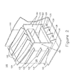
- FIG. 2 is a cutaway rear perspective view of the nozzle tip of FIG. 1 ;
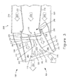
- FIG. 3 is a partial cross-sectional side view showing the nozzle tip of FIGS. 1 and 2 connected to a pulverized solid fuel pipe of a pulverized solid fuel-fired furnace;
- FIG. 4 is a photograph of a water table test which illustrates separate air-fuel jets exiting the nozzle tip of FIGS. 1-3 ;
- FIG. 5 is a partial cross-sectional side view showing a nozzle tip according to an alternative exemplary embodiment.
- FIG. 6 is a plan view from the outlet side of an alternative embodiment of the nozzle tip of the present invention employing air deflectors.
- FIG. 7 is a rear perspective view of the nozzle tip of FIG. 6 .
- FIG. 8 is a computer-generated simulation showing the predicted particle flow concentration for the nozzle tip of FIGs. 6 and 7 .
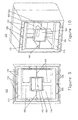
- FIG. 9 is a plan view from the outlet side of an alternative embodiment of the nozzle tip of the present invention employing a center bluff.
- FIG. 10 is a rear perspective view of the nozzle tip of FIG. 9 .
- FIG. 11 is a computer-generated simulation showing the predicted particle flow concentration for the nozzle tip of FIGs. 9 and 10 .
- FIG. 12 is a plan view from the outlet side of an alternative embodiment of the nozzle tip of the present invention employing a recessed center bluff.
- FIG. 13 is a rear perspective view of the nozzle tip of FIG. 12 .
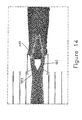
- FIG. 14 is a computer-generated simulation showing the predicted particle flow concentration for the nozzle tip of FIGs. 12 and 13 .
- FIG. 15 is a plan view from the outlet side of an "X"-shaped nozzle tip being an alternative embodiment of and of the present invention.
- FIG. 16 is a rear perspective view of the nozzle tip of FIG. 15 .
- FIG. 17 is a computer-generated simulation showing the predicted particle flow concentration for the nozzle tip of FIGs. 15 and 16 .
- FIG. 18 is a plan view from the outlet side of a nozzle tip employing a flow splitter with diffuser blocks.
- FIG. 19 is a rear perspective view of the nozzle tip of FIG. 18 .
- FIG. 20 is a computer-generated simulation showing the predicted particle flow concentration for the nozzle tip of FIGs. 18 and 19 .
- FIG. 21 is a plan view from the outlet side of a round coal nozzle tip.
- FIG. 22 is a rear perspective view of the nozzle tip of FIG. 21 .
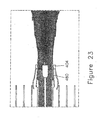
- FIG. 23 is a computer-generated simulation showing the predicted particle concentration for the nozzle tip of FIGs. 21 and 22 .
- FIG. 24 is a plan view from the outlet side of a round coal nozzle tip with a recessed swirler.
- FIG. 25 is a rear perspective view of the nozzle tip of FIG. 24 .
- FIG. 26 is a computer-generated simulation showing the predicted particle concentration for the nozzle tip of FIGs. 24 and 25 .
- a low NO X pulverized solid fuel nozzle tip and more specifically, a pulverized solid fuel nozzle tip that provides separate and discrete air/pulverized fuel jets for use in a firing system of a pulverized solid fuel-fired furnace.
- a pulverized solid fuel nozzle tip that provides separate and discrete air/pulverized fuel jets for use in a firing system of a pulverized solid fuel-fired furnace.
- penetration of the separate and discrete air/pulverized fuel jets is decreased, and a surface area thereof is increased.
- NO X emissions of the pulverized solid fuel-fired furnace are substantially reduced and/or effectively minimized, as will hereinafter be described in further detail with reference to the accompanying drawings.
- a nozzle tip 100 having an inlet end 102 and an outlet end 104 includes a secondary air (SA) shroud 110 and a primary air (PA) shroud 120 enclosed therein.
- the PA shroud 120 includes PA shroud side plates 122, a PA shroud top plate 124 and a PA shroud bottom plate 126.
- the SA shroud 110 is supported by supports 130 located between the SA shroud 110 and the PA shroud 120. Further, an SA duct 135 substantially surrounds the PA shroud 110. Specifically, the SA duct 135 includes spaces created between the supports 130 and the PA shroud top plate 124, the supports 130 and the PA shroud bottom plate 126, and spaces created between the supports 130 and the PA shroud side plates 122.
- a primary air-pulverized solid fuel (PA-PSF) duct 150 is formed in a space created within the PA shroud side plates 122, the PA shroud top plate 124 and the PA shroud bottom plate 126.
- Splitter plates 160 are formed in the PA-PSF duct 150. As shown in FIG. 1 , the splitter plates 160 are disposed in the PA-PSF duct 150, and extend substantially parallel to corresponding surfaces defining the PA shroud top plate 124 and the PA shroud bottom plate 126, respectively.
- the splitter plates 160 are formed to have a curve. Specifically, portions of the splitter plates 160 closest to the nozzle tip outlet end 104 curve outward, e.g., away from a central inner area of the PA-PSF duct 150. More specifically, a portion of an upper splitter plate 160 curves toward the PA shroud top plate 124, while a portion of a lower splitter plate 160 curves toward the PA shroud bottom plate 126, as shown in FIG. 1 .
- alternative exemplary embodiments are not limited thereto.
- each of the splitter plates 160 may be formed to be substantially straight, e.g., rectilinear, or, alternatively, the splitter plates 160 may be formed to have a series of discrete angular, e.g., not smoothly curved, bends.
- the splitter plates 160 include shear bars 170.
- the upper splitter plate 160 includes a first shear bar 170 disposed proximate to the outlet 104 and on the portion of the upper splitter plate 160 which curves toward the PA shroud top plate 124, while the lower splitter plate 160 includes a second shear bar 170 disposed proximate to the outlet 104 and on the portion of the lower splitter plate 160 which curves toward the PA shroud bottom plate 126.
- first shear bar 170 is disposed on a surface of the upper splitter plate 160 which faces the PA shroud top plate 124, while the second shear bar 170 is disposed on a surface of the lower splitter plate 160 which faces the PA shroud bottom plate 126.
- shear bars 170 may be located at different locations on the splitter plates 160 than as shown in FIG. 1 .
- the shear bars 170 may be located on different, e.g., opposite, surfaces of the upper splitter plate 160 and/or the lower splitter plate 160.
- a flow splitter 180 is disposed in the PA-PSF duct 150 between the splitter plates 160.
- the flow splitter 180 is disposed approximately midway between ends of the curved portions of the splitter plates 160 (described in greater detail above).
- the flow splitter 180 extends between the PA shroud side plates 122, as shown in FIG. 1 , but alternative exemplary embodiments are not limited thereto.
- the flow splitter 180 may not extend fully between the PA shroud side plates 122, e.g., may have length less than a distance measured between the PA shroud side plates 122.
- the flow splitter 180 may be located in a different area of the PA-PSF duct 150, e.g., not approximately midway between the ends of the curved portions of the splitter plates 160 in alternative exemplary embodiments.
- the flow splitter 180 may extend from one PA shroud side plate 122 to approximately the mid point of the PA shroud.
- a location of the flow splitter 180 between the edges of the splitter plates 160 may be adjusted based upon predetermined requirements of PA-PSF jets, discussed in greater detail below.
- the flow splitter 180 may be disposed closer to one splitter plate 160 than another.
- the flow splitter 180 has a substantially triangular wedge shape in cross section, as shown in FIG. 1 , but alternative exemplary embodiments are not limited thereto. Rather, the flow splitter 180 may be other shapes, such as rectangular, trapezoidal, pentagonal and other polygonal shapes, for example, or any other shape suitable for operative purposes thereof, e.g., to assist separation of an air/pulverized fuel jet into separate and discrete jets which do not recombine until after traveling a predetermined distance into a furnace, as will be described in further detail below with reference to FIG. 3 .
- the flow splitter 180 may include one or more shear bars 170 disposed thereon.
- shear bars 170 may be disposed on additional surfaces such as the PA shroud side plates 122, the PA shroud top plate 124 and/or the PA shroud bottom plate 126, for example, but alternative exemplary embodiments are not limited thereto.
- the sides of the SA shroud 110 and the PA shroud side plates 122 each have an aperture 190 therethrough.
- the apertures 190 are aligned along a common axis which serves as a pivot point 191 (best shown in FIG. 3 ) to allow the nozzle tip 100 to tilt up and down during operation.
- the nozzle tip 100 is mounted on a pulverized solid fuel pipe nozzle 200 of a pulverized solid fuel pipe 210 mounted within a pulverized solid fuel-air delivery conduit 220. More specifically, the pulverized solid fuel pipe nozzle 200 is attached to the aperture 190 at the nozzle tip inlet end 102 ( FIG. 1 ) of the nozzle tip 100.
- the pulverized solid fuel pipe 210 delivers a fuel flow 230, e.g., a PSF-PA inlet jet 230, to the PS-PSF duct 150 through the nozzle tip inlet end 102, while secondary air 240 is delivered to the SA duct 135 of the nozzle tip 100, as shown in FIG. 3 .
- Seal plates 250 attached to the pulverized solid fuel pipe nozzle 200 form an annular sealing shroud (not shown) which prevents the PA-PSF inlet jet 230 from entering the SA duct 135 and/or the SA 240 from entering the PA-PSF duct 150.
- the seal plates 250 may be omitted in an alternative exemplary embodiment.
- the PA-PSF duct 150 of the nozzle tip 100 is divided into three (3) chambers. Specifically, the PA-PSF duct 150 is divided into an upper PA-PSF chamber 260, a middle PA-PSF chamber 270 and a lower PA-PSF chamber 280. More specifically, the upper PA-PSF chamber 260 is defined by the PA shroud top plate 124 and an upper (with respect to FIG. 3 ) splitter plate 160, the middle PA-PSF chamber 270 is defined by the upper splitter plate 160 and a lower (with respect to FIG. 3 ) splitter plate 160, and the lower PA-PSF chamber 280 is defined by the lower splitter plate 160 and the PA shroud bottom plate 126. As described above in greater detail and illustrated in FIG.
- the flow splitter 180 is thus disposed within the middle PA-PSF jet chamber 270, while the shear bars 170 are disposed on respective splitter plates 160 within the upper PA-PSF jet chamber 260 and the lower PA-PSF jet chamber 280, but alternative exemplary embodiments are not limited thereto.
- the shear bars 170, or an additional shear bar 170 may be disposed within the middle PA-PSF jet chamber 270, while the flow splitter, or additional flow splitters 180, may be disposed in any or all of the upper PA-PSF jet chamber 260, the middle PA-PSF jet chamber 270 and/or the lower PA-PSF jet chamber 280.
- the nozzle tip 100 During operation of a pulverized solid fuel-fired furnace (not shown) having the nozzle tip 100, the PA-PSF inlet jet 230 is supplied to the PA-PSF duct 150 of the nozzle tip 100 through the pulverized solid fuel pipe 210 via the pulverized solid fuel pipe nozzle 200.
- the PA-PSF inlet jet 230 is divided into three (3) separate jets, e.g., an upper PA-PSF jet 290, a middle PA-PSF jet 300 and a lower PA-PSF jet 310, as shown in FIG. 3 .
- the three (3) separate jets are formed based on the geometry, described above in greater detail, of the nozzle tip 100. More specifically, division of the PA-PSF inlet jet 230 into the three (3) separate jets is based upon physical dimensions of each of the upper PA-PSF chamber 260, the middle PA-PSF chamber 270 and the lower PA-PSF chamber 280.
- the upper PA-PSF jet 290, the middle PA-PSF jet 300 and the lower PA-PSF jet 310 exit the nozzle tip 100 at the nozzle tip outlet end 104 into the pulverized solid fuel-fired furnace (not shown).
- the upper PA-PSF jet 290, the middle PA-PSF jet 300 and the lower PA-PSF jet 310 exit the nozzle tip 100 form two (2) separate, e.g., discrete, jets, namely an upper PA-PSF outlet jet 320 and a lower PA-PSF outlet jet 330, as shown in FIG. 3 .
- Components within the PA-PSF duct 150 e.g., the splitter plates 160, the shear bars 170 and the flow splitter 180, as well as the arrangement of the abovementioned components, described in greater detail above, determine formation of the upper PA-PSF outlet jet 320 and the lower PA-PSF outlet jet 330.
- the flow splitter 180 causes the upper PA-PSF jet 290, the middle PA-PSF jet 300 and the lower PA-PSF jet 310 to combine such that the upper PA-PSF outlet jet 320 and the lower PA-PSF outlet jet 330 exit the nozzle tip 100 as separate, discrete jets, e.g., such that the upper PA-PSF outlet jet 320 and the lower PA-PSF outlet jet 330 do not mix with each other after exiting the nozzle tip 100 and entering the pulverized solid fuel-fired furnace (not shown). More specifically, the upper PA-PSF outlet jet 320 and the lower PA-PSF outlet jet 330 remain separate and discrete for a predetermined distance after leaving the nozzle tip 100, as shown in FIG. 4 .
- the upper PA-PSF outlet jet 320 and the lower PA-PSF outlet jet 330 remain separate and discrete for a distance from the nozzle tip equal to approximately 2 to approximately 8 jet diameters of the upper PA-PSF outlet jet 320 and/or the lower PA-PSF outlet jet 330, after which the upper PA-PSF outlet jet 320 and the lower PA-PSF outlet jet 330 begin to disburse and mix with gases in the furnace, but alternative exemplary embodiments are not limited thereto.
- portions thereof e.g., on a periphery of the upper PA-PSF outlet jet 320 and the lower PA-PSF outlet jet 330, may recirculate back towards the center flow splitter 180, thereby enhancing ignition and flame stability of the upper PA-PSF outlet jet 320 and the lower PA-PSF outlet jet 330.
- NO X emissions from a pulverized solid fuel-fired furnace utilizing the nozzle tip 100 according to an exemplary embodiment are substantially reduced as compared to NO X emissions from a pulverized solid fuel-fired furnace utilizing a nozzle tip of the prior art.
- test results have shown that, according to one exemplary embodiment, improvements, e.g., reductions, in NO X emissions of approximately 20 percent to approximately 30 percent are obtained, due to implementation of the nozzle tip 100 (with other parameters affecting NO X emissions at equivalent levels).
- improvements e.g., reductions, in NO X emissions of approximately 20 percent to approximately 30 percent are obtained, due to implementation of the nozzle tip 100 (with other parameters affecting NO X emissions at equivalent levels).
- further testing shows that the nozzle tip according to an exemplary embodiment reduces NO X emissions by approximately 36 percent to approximately 50 percent as compared to other known nozzle tips of the prior art.
- the flow splitter 180 divides the middle PA-PSF jet 300, into an upper portion 350 and a lower portion 360.
- the upper portion 350 of the PA-PSF jet 300 combines with the upper PA-PSF jet 290 to form the upper PA-PSF outlet jet 320.
- the lower portion 360 of the PA-PSF jet 300 combines with the lower PA-PSF jet 310 to form the lower PA-PSF outlet jet 330.
- an initial separation distance between the upper PA-PSF outlet jet 320 and the lower PA-PSF outlet jet 330, dimensions thereof (e.g., diameters), and a distance which the upper PA-PSF outlet jet 320 and the lower PA-PSF outlet jet 330 travel after exiting the nozzle tip 100 before disbursing is determined base on the physical dimensions, shape, and placement of the splitter plates 160 and the flow splitter 180 within the PA-PSF duct 150.
- Bent portions 340 on the PA shroud top plate 124 and the PA shroud bottom plate 126 near the nozzle tip outlet end 104 further prevent mixing of the upper PA-PSF outlet jet 320 and the lower PA-PSF outlet jet 330 after leaving the nozzle tip 100.
- the bent portions 340 bend outward, e.g., away from the upper PA-PSF outlet jet 320 and the lower PA-PSF outlet jet 330 exiting the nozzle tip 100.
- the PA-PSF inlet jet 230 is evenly divided by the splitter plates 160 in the PA-PSF duct 150 such that the upper PA-PSF outlet jet 320 and the lower PS-PSF outlet jet 330 each include approximately 50 percent of a total flow through the nozzle tip 100, e.g., each include approximately 50 percent of the PA-PSF inlet jet 230, but alternative exemplary embodiments are not limited thereto. Further, proportions of jet flow in the upper PA-PSF chamber 260, the middle PA-PSF chamber 270 and the lower PA-PSF chamber 280 may be substantially equally divided, e.g., each having approximately 1/3 of the total flow through the nozzle tip 100.
- proportions of jet flow in the upper PA-PSF chamber 260, the middle PA-PSF chamber 270 and the lower PA-PSF chamber 280 may be approximately 30 percent, approximately 40 percent and approximately 30 percent, respectively.
- the upper PA-PSF outlet jet 320 and the lower PA-PSF outlet jet 330 are separate and discrete, and enter a combustion chamber of the pulverized solid fuel-fired furnace (not shown) through the nozzle tip outlet end 104 of the nozzle tip 100 as separate and discrete jets. Further, the upper PA-PSF outlet jet 320 and the lower PA-PSF outlet jet 330 remain separate and discrete in the combustion chamber. Specifically, the upper PA-PSF outlet jet 320 and the lower PA-PSF outlet jet 330 do not mix until traveling a predetermined distance after leaving the nozzle tip 100 according to an exemplary embodiment, as best shown in FIG. 4 and described above in greater detail with reference to FIG. 3 .
- the flow splitter 180 is omitted, as shown in FIG. 5 .
- the same reference numerals in FIG. 5 denote the same or like components as shown in FIG. 3 , and any repetitive detailed description thereof of has been omitted.
- the middle PA-PSF jet 300 is dispersed whereby an upper portion 350 thereof combines with the upper PA-PSF jet 290 to form the upper PA-PSF outlet jet 320, and the lower portion 360 thereof combines with the lower PA-PSF jet 310 to form the lower PA-PSF outlet jet 330.
- a low pressure area is formed in a region substantially between the upper PA-PSF outlet jet 320 and the lower PS-PSF outlet jet 330, relative to pressures of other areas substantially adjacent to (or even within) each of the upper PA-PSF outlet jet 320 and the lower PS-PSF outlet jet 330.
- the low pressure area substantially between the upper PA-PSF outlet jet 320 and the lower PS-PSF outlet jet 330 provides a low resistance path to permit a combustion flame to ignite the fuel (e.g., coal particles) disposed within the inner portion of the outlet fuel jet, thereby consuming oxygen therein.
- the fuel e.g., coal particles
- oxygen in the low pressure region is effectively depleted, resulting in less oxygen available for NO X formation, thereby substantially decreasing NO X emissions from a pulverized solid fuel-fired boiler having the nozzle tip according to an exemplary embodiment.
- computational fluid dynamics modeling and combustion testing of a nozzle tip according to an exemplary embodiment suggest that concentrating the coal particles towards the outside of the coal stream is advantageous for reducing NO X emissions while minimizing unburned carbon levels.
- this embodiment shown and described hereinbefore in Figs. 1-3 having a flow splitter 180 provides a similar low pressure area disposed at the an outer surface of the flow splitter.
- the low pressure area substantially between the upper PA-PSF outlet jet 320 and the lower PS-PSF outlet jet 330 results in a combustion flame being drawn to the low pressure area, thereby consuming oxygen therein.
- oxygen in the low pressure region is effectively depleted, resulting in less oxygen available for NO X formation, thereby substantially decreasing NO X emissions from a pulverized solid fuel-fired boiler having the nozzle tip according to an exemplary embodiment.
- each of the separate and discrete jets having a decreased diameter relative to a diameter of the upper PA-PSF outlet jet 320.
- a total wetted perimeter P T of the two separate and discrete jets having the diameter D 1 is substantially increased or effectively improved as compared to a wetted perimeter P of a single jet, e.g., the PA-PSF inlet jet 230 having the cross-sectional area A.
- jet dispersion e.g., jet breakdown, is further increased.
- the increased total wetted perimeter of the separate and distinct jets allows for controlled amounts of air available at a near field of combustion in the combustion chamber to mix with pulverized solid fuel, thereby improving early flame stabilization and devolatilization.
- the increased total wetted perimeter also allows for improved mixing and recirculation of hot products of combustion over a greater area of the fuel jet, also resulting in improved early flame stabilization and early devolatilization of the fuel and/or fuel-bound nitrogen in an oxygen-limited, fuel-rich substoichiometric region of a near field of a region downstream of the nozzle tip 100.
- the nozzle tip 100 provides at least the advantages of decreased primary air/pulverized fuel jet penetration and increased primary air/pulverized fuel jet surface area, wetted area and dispersion, thereby enhancing early ignition, early flame stabilization, fuel devolatilization and early fuel bound nitrogen release.
- NO X emissions from a pulverized solid fuel-fired boiler having the nozzle tip in accordance with an exemplary embodiment of the present invention are substantially decreased or effectively reduced.
- nozzle tip according to an exemplary embodiment in a boiler designed to have reduced main burner zone ("MBZ") stoichiometry, e.g., in a staged combustion environment in which it is desirable to initiate combustion closer to the nozzle tip (as compared to boilers having a high MBZ stoichiometry), but alternative exemplary embodiments are not limited thereto.
- MBZ main burner zone
- FIG. 6 is a plan view from the outlet side of an alternative embodiment of the nozzle tip of the present invention employing air deflectors. This embodiment is similar to that of FIG. 5 , with the exceptions that splitter plates 160 do not diverge, shear bars 170 are not employed and air deflectors 175 are added as shown.
- FIG. 7 is a rear perspective view of the nozzle tip of FIG. 6 .
- splitter plates 160 are shown as well as the air deflectors 175.
- FIG. 8 is a computer-generated simulation showing the predicted particle concentration for the nozzle tip of FIGs. 6 and 7 .
- a computer model was generates using applicable conditions to predict how the particles were concentrated after they had passed through the nozzle. These simulations are important in designing a low NOx nozzle.
- FIG. 9 is a plan view from the outlet side of an alternative embodiment of the nozzle tip of the present invention employing a center bluff.
- FIG. 10 is a rear perspective view of the nozzle tip of FIG. 9 . This embodiment will be described with reference to both FIG. 9 and 10 .
- a splitter plate 160 is positioned through the center of outlet 104 in both a vertical direction and a horizontal direction.
- the flow splitter 180 having a wedge shape having a base 483 and an apex edge 481.
- Flow splitter 180 is positioned at the center relative to the vertical and horizontal directions. It is also placed at the rear of thee nozzle 100, flush with the outlet 104.
- This embodiment also includes air deflectors 175.
- FIG. 11 is a computer-generated simulation showing the predicted particle flow concentration for the nozzle tip of FIGs. 9 and 10 . There is a pattern of particle distribution to downstream from the nozzle. Since flow splitter 180 has a hollow base 181, particles are allowed to recirculate into flow splitter 180.
- FIG. 12 is a plan view from the outlet side of an alternative embodiment of the nozzle tip of the present invention employing a recessed center bluff.
- FIG. 13 is a rear perspective view of the nozzle tip of FIG. 12 . The elements of this embodiment will be described in connection with both FIGs. 12 and 13 .
- This embodiment includes multiple splitter plates 160 oriented in both the vertical and horizontal directions.
- Flow splitter 180 is enclosed with a flat base 481.
- the flow splitter 180 0 is offset, or recessed inward away from the outlet 104 edge as compared with the flow splitter of FIGs. 9 and 10 .
- FIG. 14 is a computer-generated simulation showing the predicted particle flow concentration for the nozzle tip of FIGs. 12 and 13 .
- the apex edge 483 of the flow splitter cuts through the oncoming flow of particles and splits the flow into a flow above and below the flow splitter 180. There is a turbulent zone immediately downstream from the base 481 of flow splitter 180.
- FIG. 15 is a plan view from the outlet side of an "X"-shaped nozzle tip being an alternative embodiment of and of the present invention.
- FIG. 16 is a rear perspective view of the nozzle tip of FIG. 15 . This embodiment will be described in connection with both figures 15 and 16 .
- Outlet 104 has a general "X" shape, with the outlet 104 extending outward from a central location 108, into 4 outlet lobes 106 of outlet 104. Even though 4 lobes are shown here, any number of lobes radiating from the central location 108 envisioned by this invention.
- a flow splitter 180 is positioned on a splitter plate 160 oriented horizontal across the nozzle 100 approximately evenly bisecting outlet 104 into an upper half and a lower half.
- the flow splitter 180 has a leading section 181 and a trailing section 182 both inclines toward a center of the flow splitter both along its length and width.
- the leading section 181 has a 4-sided pyramid shape with a leading apex 183 and a base (not shown).
- the trailing section [182] also is shaped like a 4-sided pyramid having an apex 184 and a base (not shown). In this embodiment, the bases of the pyramids are together with the apices pointing away from each other.
- Each side of the leading section 181 of the flow splitter 180 are positioned, sized and angled to deflect incident flow toward its nearest outlet lobe 105. This effectively splits the flow into 4 components, one for each outlet lobe 106.
- FIG. 17 is a computer-generated simulation showing the predicted particle flow concentration for the nozzle tip of FIGs. 15 and 16 .
- the cross sectional shape of flow splitter 180 can be seen in this figure.
- Leading section 181 here appears having a triangular cross-sectional shape.
- Trailing section 182 also has a cross sectional shape.
- the apex 183 of leading section 181 is visible as is apex 184 of the trailing section 182.
- leading section 181 is used for the flow splitter 180. This may have a flat base, or be hollow.
- FIG. 18 is a plan view from the outlet side of a nozzle tip employing a flow splitter with diffuser blocks.
- FIG. 19 is a rear perspective view of the nozzle tip of FIG. 18 .
- the flow splitter 180 employs several diffusion blocks adjacent to each other on alternating sides of splitter plate 160.
- FIG. 20 is a computer-generated simulation showing the predicted particle flow concentration for the nozzle tip of FIGs. 18 and 19 . This shows the cross-sectional shape of the nozzle.
- the diffusion blocks 186 attached to the splitter plates 160 can be seen in cross section.
- FIG. 21 is a plan view from the outlet side of a round coal nozzle tip.
- FIG. 22 is a rear perspective view of the nozzle tip of FIG. 21 .
- This, and related embodiments are the subject of pending U.S. Patent Ser. No. 11/279,123 filed April 10, 2006 entitled "Pulverized Solid Fuel Nozzle” by Oliver G. Biggs, Jr., Kevin E. Connolly, Kevin A. Greco, Philip H Lafave and Galen H. Richards (the “Round Nozzle Tip Application”) hereby incorporated by reference as if set forth in its entirety herein. A full description of this embodiment is presented in this application.
- a circular outlet 404 houses a rotor 470 on a rotor hub 480.
- An annular air duct 435 encircles the circular outlet 404.
- the round nozzle tip 400 has a central duct 450 with a circular inlet 402 and outlet 404 that houses the rotor 470 on the rotor hub 480.
- the nozzle tip 400 for pulverized solid fuel nozzle 200 of pulverized solid fuel fired furnace that reduces NOx emissions comprises the generally cylindrical inner air shroud 410 enclosing the central duct 450 having the inlet 402, the outlet 404 and a central axis running generally from the inlet 402 to the outlet 404 generally through a center of the central duct 450.
- the inlet 402 receives a fuel flow 230.
- the nozzle tip 400 further comprises the generally cylindrical outer air shroud 420 enclosing the inner air shroud 410 and defining the annular duct 435 therebetween.
- the rotor 470 having angled blades resembling a propeller, is rotatably positioned with the central passageway 450 causing turbulence and mixing of the fuel flow 230 with air, thereby reducing the NOx emissions.
- FIG. 23 is a computer-generated simulation showing the predicted particle flow concentration for the nozzle tip of FIGs. 21 and 22 . This shows it's cross sectional structure.
- Rotor hub 480 mixes the particles as they pass through the rotor and out of outlet 404.
- FIG. 24 is a plan view from the outlet side of a round coal nozzle tip with a recessed swirler.
- FIG. 25 is a rear perspective view of the nozzle tip of FIG. 24 . This is similar to the Round Nozzle Tip Application above.
- FIGs. 21-22 show a similar structure to that FIGs. 21-22 , except that the rotor 470 is recessed within the nozzle.
- FIG. 26 is a computer-generated simulation showing the predicted particle flow concentration for the nozzle tip of FIGs. 24 and 25 . This shows it's cross sectional structure. Rotor hub 480 and outlet 408 are visible in this view.
- a nozzle tip [100] for a pulverized solid fuel pipe nozzle [200] of a pulverized solid fuel-fired furnace that reduces NOx emissions comprising: a primary air shroud [120] having an inlet [102] and an outlet [104], wherein the inlet [102] receives a fuel flow; a first splitter plate [160] disposed within the primary air shroud [120], the first splitter plate [160] and the primary air shroud [120] defining a duct [260] for receiving a first portion of the fuel flow; and a flow splitter [180] disposed within the primary air shroud [120], the flow splitter [180] having a pair of diverging surfaces which separates a second portion of the fuel flow [230] into a first split flow and a diverging second split flow, wherein the first split flow and the first portion of the fuel flow [230] combine at the outlet [104] of the primary air shroud [120] to provide a first outlet
- the nozzle tip [100] of embodiment 1, wherein the primary air shroud [120] comprises: side plate [122]; a top plate [124]; and a bottom plate [126], wherein the top plate [124] and the bottom plate [126] connect the side plate [122] together.
- nozzle tip [100] of embodiment 12 further comprising at least one of a shear bar [170] and a bluff point disposed on at least one of the first splitter plate [160] and the second splitter plate [160].
- nozzle tip of embodiment 22 further comprising:
Landscapes
- Engineering & Computer Science (AREA)
- Chemical & Material Sciences (AREA)
- Combustion & Propulsion (AREA)
- Mechanical Engineering (AREA)
- General Engineering & Computer Science (AREA)
Abstract
Description
- The present disclosure relates generally to firing systems for use with pulverized solid fuel-fired furnaces, and more specifically, to a low NOX pulverized solid fuel nozzle tip providing separate and discrete air/pulverized fuel jets for use in such firing systems.
- Pulverized solid fuel has been successfully burned in suspension in furnaces by tangential firing methods for a long time. The tangential firing method has many advantages, among them being good mixing of the pulverized solid fuel and air, stable flame conditions, and long residence time of combustion gases in the furnaces.
- Systems for delivering the pulverized solid fuel (e.g., coal) to a steam generator typically include a plurality of nozzle assemblies through which the pulverized coal is delivered, using air, into a combustion chamber of the steam generator. The nozzle assemblies are typically disposed within windboxes, which may be located proximate to the corners of the steam generator. Each nozzle assembly includes a nozzle tip, which protrudes into the combustion chamber. Each nozzle tip delivers a single stream, or jet, of the pulverized coal and air into the combustion chamber. After leaving the nozzle tip, the single pulverized coal/air jet disperses in the combustion chamber.
- Typically, the nozzle tips are arranged to tilt up and down to adjust the location of the flame within the combustion chamber. The flames produced at each pulverized solid fuel nozzle are stabilized through global heat- and mass-transfer processes. Thus, a single rotating flame envelope (e.g., a "fireball"), centrally located in the furnace, provides gradual but thorough and uniform pulverized solid fuel-air mixing throughout the entire furnace.
- Recently, more and more emphasis has been placed on minimization of air pollution. In connection with this, with reference in particular to the matter of NOX control, it is known that oxides of nitrogen are created during fossil fuel combustion primarily by two separate mechanisms which have been identified to be thermal NOX and fuel NOX. Thermal NOX results from the thermal fixation of molecular nitrogen and oxygen in the combustion air. The rate of formation of thermal NOX is extremely sensitive to local flame temperature and somewhat less sensitive to local concentration of oxygen. Virtually all thermal NOX is formed at a region of the flame which is at the highest temperature. The thermal NOX concentration is subsequently "frozen" at a level prevailing in the high temperature region by the thermal quenching of the combustion gases. The flue gas thermal NOX concentrations are, therefore, between the equilibrium level characteristic of the peak flame temperature and the equilibrium level at the flue gas temperature.
- On the other hand, fuel NOX derives from the oxidation of organically bound nitrogen in certain fossil fuels such as coal and heavy oil. The formation rate of fuel NOX is highly affected by the rate of mixing of the fossil fuel and air stream in general, and by the local oxygen concentration in particular. However, the flue gas NOX concentration due to fuel nitrogen is typically only a fraction, e.g., approximately 20 to 60 percent, of the level which would result from complete oxidation of all nitrogen in the fossil fuel. From the preceding, it should thus now be readily apparent that overall NOX formation is a function both of local oxygen levels and of peak flame temperatures.
- Although the pulverized solid fuel nozzle tips of the prior art are operative for their intended purposes, there has nevertheless been evidenced in the prior art a need for such pulverized solid fuel nozzle tips to be further improved, specifically in the pursuit of reduced air pollution, e.g., NOX emissions. More specifically, a need has been evidenced in the prior art for a new and improved low NOX pulverized solid fuel nozzle tip for use in a tangential firing system that would enable more flexibility in the control of undesirable emissions such as nitric oxides.
- According to the aspects illustrated herein, there is provided a nozzle tip for a pulverized solid fuel pipe nozzle of a pulverized solid fuel-fired furnace. The nozzle tip includes: a primary air shroud having an inlet and an outlet, wherein the inlet receives a fuel flow; and a flow separator disposed within the primary air shroud, wherein the flow separator disperses the fuel flow from the outlet to provide a fuel flow jet which reduces NOX in the pulverized solid fuel-fired furnace
- The above described and other features are exemplified by the following figures and detailed description.
- Referring now to the figures, which are exemplary embodiments, and wherein the like elements are numbered alike:
-
FIG. 1 is a cutaway front perspective view of a nozzle tip; -
FIG. 2 is a cutaway rear perspective view of the nozzle tip ofFIG. 1 ; -
FIG. 3 is a partial cross-sectional side view showing the nozzle tip ofFIGS. 1 and2 connected to a pulverized solid fuel pipe of a pulverized solid fuel-fired furnace; and -
FIG. 4 is a photograph of a water table test which illustrates separate air-fuel jets exiting the nozzle tip ofFIGS. 1-3 ; and -
FIG. 5 is a partial cross-sectional side view showing a nozzle tip according to an alternative exemplary embodiment. -
FIG. 6 is a plan view from the outlet side of an alternative embodiment of the nozzle tip of the present invention employing air deflectors. -
FIG. 7 is a rear perspective view of the nozzle tip ofFIG. 6 . -
FIG. 8 is a computer-generated simulation showing the predicted particle flow concentration for the nozzle tip ofFIGs. 6 and 7 . -
FIG. 9 is a plan view from the outlet side of an alternative embodiment of the nozzle tip of the present invention employing a center bluff. -
FIG. 10 is a rear perspective view of the nozzle tip ofFIG. 9 . -
FIG. 11 is a computer-generated simulation showing the predicted particle flow concentration for the nozzle tip ofFIGs. 9 and 10 . -
FIG. 12 is a plan view from the outlet side of an alternative embodiment of the nozzle tip of the present invention employing a recessed center bluff. -
FIG. 13 is a rear perspective view of the nozzle tip ofFIG. 12 . -
FIG. 14 is a computer-generated simulation showing the predicted particle flow concentration for the nozzle tip ofFIGs. 12 and 13 . -
FIG. 15 is a plan view from the outlet side of an "X"-shaped nozzle tip being an alternative embodiment of and of the present invention. -
FIG. 16 is a rear perspective view of the nozzle tip ofFIG. 15 . -
FIG. 17 is a computer-generated simulation showing the predicted particle flow concentration for the nozzle tip ofFIGs. 15 and 16 . -
FIG. 18 is a plan view from the outlet side of a nozzle tip employing a flow splitter with diffuser blocks. -
FIG. 19 is a rear perspective view of the nozzle tip ofFIG. 18 . -
FIG. 20 is a computer-generated simulation showing the predicted particle flow concentration for the nozzle tip ofFIGs. 18 and 19 . -
FIG. 21 is a plan view from the outlet side of a round coal nozzle tip. -
FIG. 22 is a rear perspective view of the nozzle tip ofFIG. 21 . -
FIG. 23 is a computer-generated simulation showing the predicted particle concentration for the nozzle tip ofFIGs. 21 and 22 . -
FIG. 24 is a plan view from the outlet side of a round coal nozzle tip with a recessed swirler. -
FIG. 25 is a rear perspective view of the nozzle tip ofFIG. 24 . -
FIG. 26 is a computer-generated simulation showing the predicted particle concentration for the nozzle tip ofFIGs. 24 and 25 . - As with all of the figures, elements with the same reference numbers perform the same or very similar function with the same or very similar structure. Therefore, a description in connection with one figure will apply to the element having the same reference number in all other figures.
- Disclosed herein is a low NOX pulverized solid fuel nozzle tip, and more specifically, a pulverized solid fuel nozzle tip that provides separate and discrete air/pulverized fuel jets for use in a firing system of a pulverized solid fuel-fired furnace. As compared to a nozzle providing a single air/pulverized fuel jet, penetration of the separate and discrete air/pulverized fuel jets is decreased, and a surface area thereof is increased. As a result, NOX emissions of the pulverized solid fuel-fired furnace are substantially reduced and/or effectively minimized, as will hereinafter be described in further detail with reference to the accompanying drawings.
- Referring to
FIGS. 1 and2 , anozzle tip 100 having aninlet end 102 and anoutlet end 104 includes a secondary air (SA)shroud 110 and a primary air (PA)shroud 120 enclosed therein. ThePA shroud 120 includes PAshroud side plates 122, a PA shroudtop plate 124 and a PAshroud bottom plate 126. - The
SA shroud 110 is supported bysupports 130 located between theSA shroud 110 and thePA shroud 120. Further, anSA duct 135 substantially surrounds thePA shroud 110. Specifically, theSA duct 135 includes spaces created between thesupports 130 and the PA shroudtop plate 124, thesupports 130 and the PAshroud bottom plate 126, and spaces created between thesupports 130 and the PAshroud side plates 122. - A primary air-pulverized solid fuel (PA-PSF)
duct 150 is formed in a space created within the PAshroud side plates 122, the PA shroudtop plate 124 and the PAshroud bottom plate 126.Splitter plates 160 are formed in the PA-PSF duct 150. As shown inFIG. 1 , thesplitter plates 160 are disposed in the PA-PSF duct 150, and extend substantially parallel to corresponding surfaces defining the PA shroudtop plate 124 and the PAshroud bottom plate 126, respectively. - In an exemplary embodiment, such as illustrated in
FIG. 1 , thesplitter plates 160 are formed to have a curve. Specifically, portions of thesplitter plates 160 closest to the nozzletip outlet end 104 curve outward, e.g., away from a central inner area of the PA-PSF duct 150. More specifically, a portion of anupper splitter plate 160 curves toward the PA shroudtop plate 124, while a portion of alower splitter plate 160 curves toward the PAshroud bottom plate 126, as shown inFIG. 1 . However, alternative exemplary embodiments are not limited thereto. For example, each of thesplitter plates 160 may be formed to be substantially straight, e.g., rectilinear, or, alternatively, thesplitter plates 160 may be formed to have a series of discrete angular, e.g., not smoothly curved, bends. - Still referring to
FIG. 1 , thesplitter plates 160 include shear bars 170. In an exemplary embodiment, theupper splitter plate 160 includes afirst shear bar 170 disposed proximate to theoutlet 104 and on the portion of theupper splitter plate 160 which curves toward the PA shroudtop plate 124, while thelower splitter plate 160 includes asecond shear bar 170 disposed proximate to theoutlet 104 and on the portion of thelower splitter plate 160 which curves toward the PAshroud bottom plate 126. Further, thefirst shear bar 170 is disposed on a surface of theupper splitter plate 160 which faces the PA shroudtop plate 124, while thesecond shear bar 170 is disposed on a surface of thelower splitter plate 160 which faces the PAshroud bottom plate 126. It will be noted that alternative exemplary embodiments are not limited to the abovementioned description, e.g., the shear bars 170 may be located at different locations on thesplitter plates 160 than as shown inFIG. 1 . For example, in an alternative exemplary embodiment, the shear bars 170 may be located on different, e.g., opposite, surfaces of theupper splitter plate 160 and/or thelower splitter plate 160. - A
flow splitter 180 is disposed in the PA-PSF duct 150 between thesplitter plates 160. In an exemplary embodiment, theflow splitter 180 is disposed approximately midway between ends of the curved portions of the splitter plates 160 (described in greater detail above). Further, theflow splitter 180 extends between the PAshroud side plates 122, as shown inFIG. 1 , but alternative exemplary embodiments are not limited thereto. For example, theflow splitter 180 may not extend fully between the PAshroud side plates 122, e.g., may have length less than a distance measured between the PAshroud side plates 122. In addition, theflow splitter 180 may be located in a different area of the PA-PSF duct 150, e.g., not approximately midway between the ends of the curved portions of thesplitter plates 160 in alternative exemplary embodiments. For instance, in one embodiment theflow splitter 180 may extend from one PAshroud side plate 122 to approximately the mid point of the PA shroud. Furthermore, a location of theflow splitter 180 between the edges of thesplitter plates 160 may be adjusted based upon predetermined requirements of PA-PSF jets, discussed in greater detail below. For example, in an alternative exemplary embodiment, theflow splitter 180 may be disposed closer to onesplitter plate 160 than another. - In an exemplary embodiment, the
flow splitter 180 has a substantially triangular wedge shape in cross section, as shown inFIG. 1 , but alternative exemplary embodiments are not limited thereto. Rather, theflow splitter 180 may be other shapes, such as rectangular, trapezoidal, pentagonal and other polygonal shapes, for example, or any other shape suitable for operative purposes thereof, e.g., to assist separation of an air/pulverized fuel jet into separate and discrete jets which do not recombine until after traveling a predetermined distance into a furnace, as will be described in further detail below with reference toFIG. 3 . In addition, theflow splitter 180 according to an exemplary embodiment may include one ormore shear bars 170 disposed thereon. Likewise, shear bars 170 may be disposed on additional surfaces such as the PAshroud side plates 122, the PA shroudtop plate 124 and/or the PAshroud bottom plate 126, for example, but alternative exemplary embodiments are not limited thereto. - Referring now to
FIG. 2 , the sides of theSA shroud 110 and the PAshroud side plates 122 each have anaperture 190 therethrough. Theapertures 190 are aligned along a common axis which serves as a pivot point 191 (best shown inFIG. 3 ) to allow thenozzle tip 100 to tilt up and down during operation. - Referring now to
FIG. 3 , thenozzle tip 100 is mounted on a pulverized solidfuel pipe nozzle 200 of a pulverizedsolid fuel pipe 210 mounted within a pulverized solid fuel-air delivery conduit 220. More specifically, the pulverized solidfuel pipe nozzle 200 is attached to theaperture 190 at the nozzle tip inlet end 102 (FIG. 1 ) of thenozzle tip 100. The pulverizedsolid fuel pipe 210 delivers afuel flow 230, e.g., a PSF-PA inlet jet 230, to the PS-PSF duct 150 through the nozzletip inlet end 102, whilesecondary air 240 is delivered to theSA duct 135 of thenozzle tip 100, as shown inFIG. 3 .Seal plates 250 attached to the pulverized solidfuel pipe nozzle 200 form an annular sealing shroud (not shown) which prevents the PA-PSF inlet jet 230 from entering theSA duct 135 and/or theSA 240 from entering the PA-PSF duct 150. Theseal plates 250 may be omitted in an alternative exemplary embodiment. - The PA-
PSF duct 150 of thenozzle tip 100 according to an exemplary embodiment is divided into three (3) chambers. Specifically, the PA-PSF duct 150 is divided into an upper PA-PSF chamber 260, a middle PA-PSF chamber 270 and a lower PA-PSF chamber 280. More specifically, the upper PA-PSF chamber 260 is defined by the PA shroudtop plate 124 and an upper (with respect toFIG. 3 )splitter plate 160, the middle PA-PSF chamber 270 is defined by theupper splitter plate 160 and a lower (with respect toFIG. 3 )splitter plate 160, and the lower PA-PSF chamber 280 is defined by thelower splitter plate 160 and the PAshroud bottom plate 126. As described above in greater detail and illustrated inFIG. 3 , theflow splitter 180 is thus disposed within the middle PA-PSF jet chamber 270, while the shear bars 170 are disposed onrespective splitter plates 160 within the upper PA-PSF jet chamber 260 and the lower PA-PSF jet chamber 280, but alternative exemplary embodiments are not limited thereto. For example, the shear bars 170, or anadditional shear bar 170, may be disposed within the middle PA-PSF jet chamber 270, while the flow splitter, oradditional flow splitters 180, may be disposed in any or all of the upper PA-PSF jet chamber 260, the middle PA-PSF jet chamber 270 and/or the lower PA-PSF jet chamber 280. - Operation of the
nozzle tip 100 will now be described in further detail with reference toFIG. 3 . During operation of a pulverized solid fuel-fired furnace (not shown) having thenozzle tip 100, the PA-PSF inlet jet 230 is supplied to the PA-PSF duct 150 of thenozzle tip 100 through the pulverizedsolid fuel pipe 210 via the pulverized solidfuel pipe nozzle 200. - Once inside the
nozzle tip 100 and, more specifically, once inside the PA-PSF duct 150 of thenozzle tip 100, the PA-PSF inlet jet 230 is divided into three (3) separate jets, e.g., an upper PA-PSF jet 290, a middle PA-PSF jet 300 and a lower PA-PSF jet 310, as shown inFIG. 3 . The three (3) separate jets are formed based on the geometry, described above in greater detail, of thenozzle tip 100. More specifically, division of the PA-PSF inlet jet 230 into the three (3) separate jets is based upon physical dimensions of each of the upper PA-PSF chamber 260, the middle PA-PSF chamber 270 and the lower PA-PSF chamber 280. These physical dimensions are based on a predetermined shape and placement of thesplitter plates 160 and theflow splitter 180 within the PA-PSF duct 150, for example, but are not limited thereto. As a result, an optimum division of the PA-PSF inlet jet 230 into the three (3) separate jets, e.g., the upper PA-PSF jet 290, the middle PA-PSF jet 300 and the lower PA-PSF jet 310, is obtained, based upon desired and/or actual operating conditions and characteristics of the pulverized solid fuel-fired furnace (not shown), as will be described in further detail below. - After traversing the PA-
PSF duct 150, the upper PA-PSF jet 290, the middle PA-PSF jet 300 and the lower PA-PSF jet 310 exit thenozzle tip 100 at the nozzletip outlet end 104 into the pulverized solid fuel-fired furnace (not shown). When exiting thenozzle tip 100, the upper PA-PSF jet 290, the middle PA-PSF jet 300 and the lower PA-PSF jet 310 exit thenozzle tip 100 form two (2) separate, e.g., discrete, jets, namely an upper PA-PSF outlet jet 320 and a lower PA-PSF outlet jet 330, as shown inFIG. 3 . Components within the PA-PSF duct 150, e.g., thesplitter plates 160, the shear bars 170 and theflow splitter 180, as well as the arrangement of the abovementioned components, described in greater detail above, determine formation of the upper PA-PSF outlet jet 320 and the lower PA-PSF outlet jet 330. In particular, theflow splitter 180 causes the upper PA-PSF jet 290, the middle PA-PSF jet 300 and the lower PA-PSF jet 310 to combine such that the upper PA-PSF outlet jet 320 and the lower PA-PSF outlet jet 330 exit thenozzle tip 100 as separate, discrete jets, e.g., such that the upper PA-PSF outlet jet 320 and the lower PA-PSF outlet jet 330 do not mix with each other after exiting thenozzle tip 100 and entering the pulverized solid fuel-fired furnace (not shown). More specifically, the upper PA-PSF outlet jet 320 and the lower PA-PSF outlet jet 330 remain separate and discrete for a predetermined distance after leaving thenozzle tip 100, as shown inFIG. 4 . In an exemplary embodiment, the upper PA-PSF outlet jet 320 and the lower PA-PSF outlet jet 330 remain separate and discrete for a distance from the nozzle tip equal to approximately 2 to approximately 8 jet diameters of the upper PA-PSF outlet jet 320 and/or the lower PA-PSF outlet jet 330, after which the upper PA-PSF outlet jet 320 and the lower PA-PSF outlet jet 330 begin to disburse and mix with gases in the furnace, but alternative exemplary embodiments are not limited thereto. Further, after partial disbursement of the upper PA-PSF outlet jet 320 and the lower PA-PSF outlet jet 330, portions thereof, e.g., on a periphery of the upper PA-PSF outlet jet 320 and the lower PA-PSF outlet jet 330, may recirculate back towards thecenter flow splitter 180, thereby enhancing ignition and flame stability of the upper PA-PSF outlet jet 320 and the lower PA-PSF outlet jet 330. As a result, NOX emissions from a pulverized solid fuel-fired furnace utilizing thenozzle tip 100 according to an exemplary embodiment are substantially reduced as compared to NOX emissions from a pulverized solid fuel-fired furnace utilizing a nozzle tip of the prior art. Specifically, test results have shown that, according to one exemplary embodiment, improvements, e.g., reductions, in NOX emissions of approximately 20 percent to approximately 30 percent are obtained, due to implementation of the nozzle tip 100 (with other parameters affecting NOX emissions at equivalent levels). Depending upon the type of coal burned, further testing shows that the nozzle tip according to an exemplary embodiment reduces NOX emissions by approximately 36 percent to approximately 50 percent as compared to other known nozzle tips of the prior art. - Thus, as can be seen in
FIG. 3 , theflow splitter 180 divides the middle PA-PSF jet 300, into anupper portion 350 and alower portion 360. Thus, upon exiting thenozzle tip 100, theupper portion 350 of the PA-PSF jet 300 combines with the upper PA-PSF jet 290 to form the upper PA-PSF outlet jet 320. In a similar manner, thelower portion 360 of the PA-PSF jet 300 combines with the lower PA-PSF jet 310 to form the lower PA-PSF outlet jet 330. - The physical dimensions, shape, and placement of the
splitter plates 160 and theflow splitter 180 within the PA-PSF duct 150, which result in the optimum division of the PA-PSF inlet jet 230 into the three (3) separate jets (as described above), further result in optimum formation of each of the upper PA-PSF outlet jet 320 and the lower PA-PSF outlet jet 330 according to desired and/or actual operating conditions and characteristics of the pulverized solid fuel-fired furnace (not shown). For example, an initial separation distance between the upper PA-PSF outlet jet 320 and the lower PA-PSF outlet jet 330, dimensions thereof (e.g., diameters), and a distance which the upper PA-PSF outlet jet 320 and the lower PA-PSF outlet jet 330 travel after exiting thenozzle tip 100 before disbursing is determined base on the physical dimensions, shape, and placement of thesplitter plates 160 and theflow splitter 180 within the PA-PSF duct 150. -
Bent portions 340 on the PA shroudtop plate 124 and the PAshroud bottom plate 126 near the nozzletip outlet end 104 further prevent mixing of the upper PA-PSF outlet jet 320 and the lower PA-PSF outlet jet 330 after leaving thenozzle tip 100. In an exemplary embodiment, thebent portions 340 bend outward, e.g., away from the upper PA-PSF outlet jet 320 and the lower PA-PSF outlet jet 330 exiting thenozzle tip 100. - In an exemplary embodiment, the PA-
PSF inlet jet 230 is evenly divided by thesplitter plates 160 in the PA-PSF duct 150 such that the upper PA-PSF outlet jet 320 and the lower PS-PSF outlet jet 330 each include approximately 50 percent of a total flow through thenozzle tip 100, e.g., each include approximately 50 percent of the PA-PSF inlet jet 230, but alternative exemplary embodiments are not limited thereto. Further, proportions of jet flow in the upper PA-PSF chamber 260, the middle PA-PSF chamber 270 and the lower PA-PSF chamber 280 may be substantially equally divided, e.g., each having approximately 1/3 of the total flow through thenozzle tip 100. However, alternative exemplary embodiments are not limited thereto; for example, proportions of jet flow in the upper PA-PSF chamber 260, the middle PA-PSF chamber 270 and the lower PA-PSF chamber 280 may be approximately 30 percent, approximately 40 percent and approximately 30 percent, respectively. - As described above in greater detail, the upper PA-
PSF outlet jet 320 and the lower PA-PSF outlet jet 330 are separate and discrete, and enter a combustion chamber of the pulverized solid fuel-fired furnace (not shown) through the nozzletip outlet end 104 of thenozzle tip 100 as separate and discrete jets. Further, the upper PA-PSF outlet jet 320 and the lower PA-PSF outlet jet 330 remain separate and discrete in the combustion chamber. Specifically, the upper PA-PSF outlet jet 320 and the lower PA-PSF outlet jet 330 do not mix until traveling a predetermined distance after leaving thenozzle tip 100 according to an exemplary embodiment, as best shown inFIG. 4 and described above in greater detail with reference toFIG. 3 . - In an alternative exemplary embodiment, the
flow splitter 180 is omitted, as shown inFIG. 5 . It will be noted that the same reference numerals inFIG. 5 denote the same or like components as shown inFIG. 3 , and any repetitive detailed description thereof of has been omitted. Referring toFIG. 5 , the middle PA-PSF jet 300 is dispersed whereby anupper portion 350 thereof combines with the upper PA-PSF jet 290 to form the upper PA-PSF outlet jet 320, and thelower portion 360 thereof combines with the lower PA-PSF jet 310 to form the lower PA-PSF outlet jet 330. - As a result of dividing the PA-
PSF inlet jet 230 into separate jets, e.g., into the upper PA-PSF outlet jet 320 and the lower PS-PSF outlet jet 330, a low pressure area is formed in a region substantially between the upper PA-PSF outlet jet 320 and the lower PS-PSF outlet jet 330, relative to pressures of other areas substantially adjacent to (or even within) each of the upper PA-PSF outlet jet 320 and the lower PS-PSF outlet jet 330. Thus, the low pressure area substantially between the upper PA-PSF outlet jet 320 and the lower PS-PSF outlet jet 330 provides a low resistance path to permit a combustion flame to ignite the fuel (e.g., coal particles) disposed within the inner portion of the outlet fuel jet, thereby consuming oxygen therein. As a result, oxygen in the low pressure region is effectively depleted, resulting in less oxygen available for NOX formation, thereby substantially decreasing NOX emissions from a pulverized solid fuel-fired boiler having the nozzle tip according to an exemplary embodiment. Specifically, computational fluid dynamics modeling and combustion testing of a nozzle tip according to an exemplary embodiment suggest that concentrating the coal particles towards the outside of the coal stream is advantageous for reducing NOX emissions while minimizing unburned carbon levels. One will appreciate that this embodiment shown and described hereinbefore inFigs. 1-3 having aflow splitter 180 provides a similar low pressure area disposed at the an outer surface of the flow splitter. - Dividing the PA-
PSF inlet jet 230 into separate and discrete jets, e.g., into the upper PA-PSF outlet jet 320 and the lower PS-PSF outlet jet 330, results in a low pressure area in a region substantially between the upper PA-PSF outlet jet 320 and the lower PS-PSF outlet jet 330, relative to pressures of other areas substantially adjacent to (or even within) each of the upper PA-PSF outlet jet 320 and the lower PS-PSF outlet jet 330. Thus, the low pressure area substantially between the upper PA-PSF outlet jet 320 and the lower PS-PSF outlet jet 330 results in a combustion flame being drawn to the low pressure area, thereby consuming oxygen therein. As a result, oxygen in the low pressure region is effectively depleted, resulting in less oxygen available for NOX formation, thereby substantially decreasing NOX emissions from a pulverized solid fuel-fired boiler having the nozzle tip according to an exemplary embodiment. - In addition, dividing the PA-
PSF inlet jet 230 into the separate and discrete jets, e.g., into the upper PA-PSF outlet jet 320 and the lower PS-PSF outlet jet 330, further results in each of the separate and discrete jets having a decreased diameter relative to a diameter of the upper PA-PSF outlet jet 320. More specifically, assuming a cross-sectional surface area A of the PA-PSF inlet jet 230 having a diameter a diameter D, the upper PA-PSF outlet jet 320 and the lower PS-PSF outlet jet 330 each have adiameter 
PSF outlet jet 320 and an area of the lower PS-PSF outlet jet 330 is equal to A). Thus, jet penetration for the separate and discrete jets (compared to a single jet of equivalent area) decreases while jet dispersion thereof increases, since jet penetration is directly proportional to jet diameter and jet dispersion is indirectly proportional to jet diameter. - Furthermore, a total wetted perimeter PT of the two separate and discrete jets having the diameter D1 is substantially increased or effectively improved as compared to a wetted perimeter P of a single jet, e.g., the PA-
PSF inlet jet 230 having the cross-sectional area A. Specifically, the upper PA-PSF outlet jet 320 and the lower PS-PSF outlet jet 330, each having thediameter 

nozzle tip 100. - Thus, the
nozzle tip 100 according to exemplary embodiments described herein provides at least the advantages of decreased primary air/pulverized fuel jet penetration and increased primary air/pulverized fuel jet surface area, wetted area and dispersion, thereby enhancing early ignition, early flame stabilization, fuel devolatilization and early fuel bound nitrogen release. As a result, NOX emissions from a pulverized solid fuel-fired boiler having the nozzle tip in accordance with an exemplary embodiment of the present invention are substantially decreased or effectively reduced. The aforementioned advantages are apparent when implementing the nozzle tip according to an exemplary embodiment in a boiler designed to have reduced main burner zone ("MBZ") stoichiometry, e.g., in a staged combustion environment in which it is desirable to initiate combustion closer to the nozzle tip (as compared to boilers having a high MBZ stoichiometry), but alternative exemplary embodiments are not limited thereto. -
FIG. 6 is a plan view from the outlet side of an alternative embodiment of the nozzle tip of the present invention employing air deflectors. This embodiment is similar to that ofFIG. 5 , with the exceptions thatsplitter plates 160 do not diverge, shear bars 170 are not employed andair deflectors 175 are added as shown. -
FIG. 7 is a rear perspective view of the nozzle tip ofFIG. 6 . Heresplitter plates 160 are shown as well as theair deflectors 175. -
FIG. 8 is a computer-generated simulation showing the predicted particle concentration for the nozzle tip ofFIGs. 6 and 7 . In this, and all following simulations, a computer model was generates using applicable conditions to predict how the particles were concentrated after they had passed through the nozzle. These simulations are important in designing a low NOx nozzle. - No simulation data was generated for the areas in white. In this case, it was the air passing through the
secondary air nozzle 135. -
FIG. 9 is a plan view from the outlet side of an alternative embodiment of the nozzle tip of the present invention employing a center bluff.FIG. 10 is a rear perspective view of the nozzle tip ofFIG. 9 . This embodiment will be described with reference to bothFIG. 9 and 10 . - A
splitter plate 160 is positioned through the center ofoutlet 104 in both a vertical direction and a horizontal direction. Here theflow splitter 180 having a wedge shape having a base 483 and anapex edge 481.Flow splitter 180 is positioned at the center relative to the vertical and horizontal directions. It is also placed at the rear ofthee nozzle 100, flush with theoutlet 104. This embodiment also includesair deflectors 175. -
FIG. 11 is a computer-generated simulation showing the predicted particle flow concentration for the nozzle tip ofFIGs. 9 and 10 . There is a pattern of particle distribution to downstream from the nozzle. Sinceflow splitter 180 has ahollow base 181, particles are allowed to recirculate intoflow splitter 180. -
FIG. 12 is a plan view from the outlet side of an alternative embodiment of the nozzle tip of the present invention employing a recessed center bluff.FIG. 13 is a rear perspective view of the nozzle tip ofFIG. 12 . The elements of this embodiment will be described in connection with bothFIGs. 12 and 13 . - This embodiment includes
multiple splitter plates 160 oriented in both the vertical and horizontal directions.Flow splitter 180 is enclosed with aflat base 481. Theflow splitter 180 0is offset, or recessed inward away from theoutlet 104 edge as compared with the flow splitter ofFIGs. 9 and 10 . -
FIG. 14 is a computer-generated simulation showing the predicted particle flow concentration for the nozzle tip ofFIGs. 12 and 13 . Theapex edge 483 of the flow splitter cuts through the oncoming flow of particles and splits the flow into a flow above and below theflow splitter 180. There is a turbulent zone immediately downstream from thebase 481 offlow splitter 180. -
FIG. 15 is a plan view from the outlet side of an "X"-shaped nozzle tip being an alternative embodiment of and of the present invention.FIG. 16 is a rear perspective view of the nozzle tip ofFIG. 15 . This embodiment will be described in connection with bothfigures 15 and 16 . -
Outlet 104 has a general "X" shape, with theoutlet 104 extending outward from a central location 108, into 4outlet lobes 106 ofoutlet 104. Even though 4 lobes are shown here, any number of lobes radiating from the central location 108 envisioned by this invention. - A
flow splitter 180 is positioned on asplitter plate 160 oriented horizontal across thenozzle 100 approximately evenly bisectingoutlet 104 into an upper half and a lower half. - The
flow splitter 180 has a leadingsection 181 and a trailingsection 182 both inclines toward a center of the flow splitter both along its length and width. The leadingsection 181 has a 4-sided pyramid shape with aleading apex 183 and a base (not shown). - The trailing section [182] also is shaped like a 4-sided pyramid having an apex 184 and a base (not shown). In this embodiment, the bases of the pyramids are together with the apices pointing away from each other.
- Each side of the leading
section 181 of theflow splitter 180 are positioned, sized and angled to deflect incident flow toward its nearest outlet lobe 105. This effectively splits the flow into 4 components, one for eachoutlet lobe 106. -
FIG. 17 is a computer-generated simulation showing the predicted particle flow concentration for the nozzle tip ofFIGs. 15 and 16 . The cross sectional shape offlow splitter 180 can be seen in this figure. Leadingsection 181 here appears having a triangular cross-sectional shape. Trailingsection 182 also has a cross sectional shape. The apex 183 of leadingsection 181 is visible as is apex 184 of the trailingsection 182. - In an alternative embodiment, only a leading
section 181 is used for theflow splitter 180. This may have a flat base, or be hollow. -
FIG. 18 is a plan view from the outlet side of a nozzle tip employing a flow splitter with diffuser blocks.FIG. 19 is a rear perspective view of the nozzle tip ofFIG. 18 . These embodiments are the subject ofU.S. Patent 6,439,136 B1 issued Aug. 27, 2002 to Jeffrey S. Mann and Ronald H. Nowak , hereby incorporated by reference as if set forth in its entirety herein. A full description of this embodiment is presented in this application. - Here the
flow splitter 180 employs several diffusion blocks adjacent to each other on alternating sides ofsplitter plate 160. -
FIG. 20 is a computer-generated simulation showing the predicted particle flow concentration for the nozzle tip ofFIGs. 18 and 19 . This shows the cross-sectional shape of the nozzle. The diffusion blocks 186 attached to thesplitter plates 160 can be seen in cross section. -
FIG. 21 is a plan view from the outlet side of a round coal nozzle tip.FIG. 22 is a rear perspective view of the nozzle tip ofFIG. 21 . This, and related embodiments are the subject of pendingU.S. Patent Ser. No. 11/279,123 filed April 10, 2006 - A
circular outlet 404 houses arotor 470 on arotor hub 480. Anannular air duct 435 encircles thecircular outlet 404. Theround nozzle tip 400 has acentral duct 450 with acircular inlet 402 andoutlet 404 that houses therotor 470 on therotor hub 480. Theannular air duct 435 between anouter shroud 420 and aninner shroud 410, encircles thecircular outlet 404. Hence, thenozzle tip 400 for pulverizedsolid fuel nozzle 200 of pulverized solid fuel fired furnace that reduces NOx emissions comprises the generally cylindricalinner air shroud 410 enclosing thecentral duct 450 having theinlet 402, theoutlet 404 and a central axis running generally from theinlet 402 to theoutlet 404 generally through a center of thecentral duct 450. Theinlet 402 receives afuel flow 230. Thenozzle tip 400 further comprises the generally cylindricalouter air shroud 420 enclosing theinner air shroud 410 and defining theannular duct 435 therebetween. Therotor 470 having angled blades resembling a propeller, is rotatably positioned with thecentral passageway 450 causing turbulence and mixing of thefuel flow 230 with air, thereby reducing the NOx emissions. -
FIG. 23 is a computer-generated simulation showing the predicted particle flow concentration for the nozzle tip ofFIGs. 21 and 22 . This shows it's cross sectional structure.Rotor hub 480 mixes the particles as they pass through the rotor and out ofoutlet 404. -
FIG. 24 is a plan view from the outlet side of a round coal nozzle tip with a recessed swirler.FIG. 25 is a rear perspective view of the nozzle tip ofFIG. 24 . This is similar to the Round Nozzle Tip Application above. - These figures show a similar structure to that
FIGs. 21-22 , except that therotor 470 is recessed within the nozzle. -
FIG. 26 is a computer-generated simulation showing the predicted particle flow concentration for the nozzle tip ofFIGs. 24 and 25 . This shows it's cross sectional structure.Rotor hub 480 and outlet 408 are visible in this view. - While the invention has been described with reference to various exemplary embodiments, it will be understood by those skilled in the art that various changes may be made and equivalents may be substituted for elements thereof without departing from the scope of the invention. In addition, many modifications may be made to adapt a particular situation or material to the teachings of the invention without departing from the essential scope thereof. Therefore, it is intended that the invention not be limited to the particular embodiment disclosed as the best mode contemplated for carrying out this invention, but that the invention will include all embodiments falling within the scope of the appended claims.
- EMBODIMENTS:
- 1. A nozzle tip [100] for a pulverized solid fuel pipe nozzle [200] of a pulverized solid fuel-fired furnace that reduces NOx emissions, the nozzle tip [100] comprising: a primary air shroud [120] having an inlet [102] and an outlet [104], wherein the inlet [102] receives a fuel flow; a first splitter plate [160] disposed within the primary air shroud [120], the first splitter plate [160] and the primary air shroud [120] defining a duct [260] for receiving a first portion of the fuel flow; and a flow splitter [180] disposed within the primary air shroud [120], the flow splitter [180] having a pair of diverging surfaces which separates a second portion of the fuel flow [230] into a first split flow and a diverging second split flow, wherein the first split flow and the first portion of the fuel flow [230] combine at the outlet [104] of the primary air shroud [120] to provide a first outlet fuel jet which exits the outlet [104] of the primary air shroud [120] separate from the second split flow.
- 2. The nozzle tip [100] of
embodiment 1, wherein the first outlet fuel jet and the second split flow exit the outlet [104] of the primary air shroud [120] separate and discrete from each other, and the first outlet fuel jet and the second split flow remain separate and discrete from each other for a predetermined distance from the outlet [104] of the primary air shroud [120]. - 3. The nozzle tip [100] of
embodiment 1, further comprising at least one of a shear bar [170] and a bluff point disposed on the first splitter plate [160]. - 4. The nozzle tip [100] of
embodiment 1, further comprising a secondary air shroud [110] disposed around the primary air shroud [120]. - 5. The nozzle tip [100] of
embodiment 1, wherein the primary air shroud [120] comprises: side plate [122]; a top plate [124]; and a bottom plate [126], wherein the top plate [124] and the bottom plate [126] connect the side plate [122] together. - 6. The nozzle tip [100] of
embodiment 1, further comprising a second splitter plate [160] disposed within the primary air shroud [120], the second splitter plate [160] and the primary air shroud [120] defining a duct [280] for receiving a third portion of the fuel flow [230]. - 7. The nozzle tip [100] of embodiment 6, wherein the flow splitter is disposed between the first splitter plate [160] and the second splitter plate [160].
- 8. The nozzle tip [100] of embodiment 6, wherein the second split flow and the third portion of the fuel flow [230] combine at the outlet [104] of the primary air shroud [120] to provide a second outlet fuel jet which exits the outlet [104] of the primary air shroud [120] separate from the first outlet fuel jet.
- 9. The nozzle tip [100] of embodiment 2, wherein the predetermined distance is in a range of approximately two (2) diameters of the first outlet fuel jet to approximately eight (8) diameters of the first outlet fuel jet, andthe first outlet fuel jet and the second split flow at least partially combine after traveling the predetermined distance from the outlet [104] of the primary air shroud [120] into the pulverized solid fuel-fired furnace.
- 10. The nozzle tip [100] of embodiment 6, wherein the first portion of the fuel flow [230] comprises approximately 30 percent of the fuel flow [230], the second portion of the fuel flow [230] comprises approximately 40 percent of the fuel flow [230], and the third portion of the fuel flow [230] comprises approximately 30 percent of the fuel flow [230].
- 11. The nozzle tip [100] of embodiment 8, wherein the first outlet fuel jet and the second outlet fuel jet each comprise approximately 50 percent of the fuel flow [230].
- 12. A nozzle tip [100] for a pulverized solid fuel pipe nozzle [200] of a pulverized solid fuel-fired furnace that reduces NOx emissions, the nozzle tip [100] comprising:
- a primary air shroud [120] having an inlet [102] and an outlet [104], wherein the inlet [102] receives a fuel flow [230];
- a first splitter plate [160] disposed within the primary air shroud [120], the first splitter plate [160] and primary air shroud [120] defining a duct [260] for receiving a first portion of the fuel flow [230]; and
- a second splitter plate [160] disposed within the primary air shroud [120], the second splitter plate [160] and primary air shroud [120] defining a duct [280] for receiving a second portion of the fuel flow [230], wherein the first splitter plate [160], the second splitter plate [160], and the primary air shroud [120] define a duct [270] for receiving a third portion of the fuel flow [230] disposed intermediate to the first portion and the second portion of the fuel flow [230], the third portion of the fuel flow [230] comprising a first split flow and a diverging second split flow, wherein
- the first split flow and the first portion of the fuel flow [230] combine at the outlet [104] of the primary air shroud [120] to provide a first outlet fuel jet which exits the outlet [104] of the primary air shroud [120], and
- the second split flow and the second portion of the fuel flow [230] combine at the outlet [104] of the primary air shroud [120] to provide a second outlet fuel jet which exits the outlet [104] of the primary air shroud [120] separate from the first outlet fuel jet.
- 13. The nozzle tip [100] of embodiment 12, wherein
the first outlet fuel jet and the second outlet fuel jet exit the outlet [104] of the primary air shroud [120] separate and discrete from each other, and
the first outlet fuel jet and the second outlet fuel jet remain separate and discrete from each other for a predetermined distance from the outlet [104] of the primary air shroud [120]. - 14. The nozzle tip [100] of embodiment 12, further comprising at least one of a shear bar [170] and a bluff point disposed on at least one of the first splitter plate [160] and the second splitter plate [160].
- 15. The nozzle tip [100] of embodiment 12, further comprising an air deflector [175] disposed on the first splitter plate [160].
- 16. The nozzle tip [100] of embodiment 13, wherein the predetermined distance is in a range of approximately two (2) diameters of one of the first outlet fuel jet and the second outlet fuel jet to approximately eight (8) diameters of the one of the first outlet fuel jet and the second outlet fuel jet, and the first outlet fuel jet and the second outlet fuel jet at least partially combine after traveling the predetermined distance from the outlet of the primary air shroud [120] [120] into the pulverized solid fuel-fired furnace.
- 17. The nozzle tip [100] of
embodiment 1 wherein the first splitter plate [160] substantially bisects the outlet [104] generally through at an approximate center, and the flow splitter [180] comprises: - a wedge shape having an apex edge [483] and a base [481], the apex edge [483] positioned closer to the inlet [102] and the base [481] positioned closer to the outlet [104],
- the flow splitter [180] extending only partially across the outlet [104], the flow splitter [180] creating turbulence in the fuel flow [230] that disperses the fuel flow [230] as the fuel flow [230] passes by the flow splitter [180] and out of outlet [104].
- 18. The nozzle tip [100] of embodiment 17 wherein the first splitter plate [160] is positioned in a substantially vertical direction.
- 19. The nozzle tip [100] of embodiment 17 wherein the first splitter plate [160] is positioned in a substantially horizontal direction.
- 20. The nozzle tip of embodiment 17 wherein the flow splitter [180] is positioned between the inlet [102] and the outlet [104] and its base [481] is recessed with respect to the outlet [104].
- 21. The nozzle tip [100] of embodiment 12, further comprising:
- a flow splitter [180] positioned between the flow splitter plates [160], the flow splitter [180] having a wedge shape with an apex edge [483] and a base [481], the apex edge [483] positioned closer to the inlet [102] and the base [481] positioned closer to the outlet [104], the flow splitter [180] extending only partially across the outlet [104], the flow splitter [180] creating turbulence in the fuel flow [230] that disperses the fuel flow [230] as the fuel flow [230] passes by the flow splitter [180] and out of outlet [104].
- 22. A nozzle tip [100] for a pulverized solid fuel pipe nozzle of a pulverized solid fuel-fired furnace that reduces NOx emissions, the nozzle tip [100] comprising:
- a primary air shroud [120] having an inlet [102] and an outlet [104], wherein:
- the inlet [102] receives solid fuel particles suspended in an airflow stream as a fuel flow, the outlet [104] generally has a cross-sectional shape with a plurality of lobes [106] each radiating from a central location;
- a flow splitter [180] disposed within the primary air shroud [120] substantially at the central location [108], the flow splitter [180] functioning to deflect solid particles of the fuel flow into each lobe [106] of the output [104] and disperse the particles within the lobes [106] allowing for combustion of the fuel flow with reduced NOx emissions.
- 23. The nozzle tip of embodiment 22 further comprising:
- a splitter plate [160] disposed within the primary shroud [120] for supporting the flow splitter [180].
Claims (7)
- A nozzle tip [400] for pulverized solid fuel nozzle [200] of pulverized solid fuel fired furnace that reduces NOx emissions, the nozzle tip [400] comprising:a generally cylindrical inner air shroud [410] enclosing a central duct [450] having an inlet [402], an outlet [404] and a central axis running generally from the inlet to the outlet [404] generally through a center of the central duct [450], wherein the inlet [402] receives a fuel flow [230];a generally cylindrical outer air shroud [420] enclosing the inner air shroud [410] and defining an annular duct [435] therebetween;a rotor [470] having angled blades resembling a propeller, rotatably positioned with the central passageway [450] causing turbulence and mixing of the fuel flow [230] with air thereby reducing the NOx emissions.
- The nozzle tip [400] of claim 1, wherein the rotor [470] is positioned closer to the inlet [402] than the outlet [404].
- The nozzle tip [400] of claim 1, wherein the rotor [470] is positioned closer to the outlet [404] than the inlet [402].
- The nozzle tip of claim 1, wherein the inlet [402] of the outer shroud [420] includes a bulbous portion disposed on at least two sides.
- The nozzle tip of claim 1, wherein the inner shroud [410] has a round outlet [404].
- The nozzle tip of claim 1, wherein the inner shroud [410] has a round inlet [402].
- The nozzle tip of claim 1, wherein the inner shroud [410] has a generally constant diameter throat.
Applications Claiming Priority (5)
| Application Number | Priority Date | Filing Date | Title |
|---|---|---|---|
| US3479608P | 2008-03-07 | 2008-03-07 | |
| US3478008P | 2008-03-07 | 2008-03-07 | |
| US12/393,439 US8701572B2 (en) | 2008-03-07 | 2009-02-26 | Low NOx nozzle tip for a pulverized solid fuel furnace |
| PCT/US2009/035801 WO2009114331A2 (en) | 2008-03-07 | 2009-03-03 | LOW NOx NOZZLE TIP FOR A PULVERIZED SOLID FUEL FURNACE |
| EP09719095.3A EP2257739B1 (en) | 2008-03-07 | 2009-03-03 | LOW NOx NOZZLE TIP FOR A PULVERIZED SOLID FUEL FURNACE |
Related Parent Applications (3)
| Application Number | Title | Priority Date | Filing Date |
|---|---|---|---|
| EP09719095.3A Division EP2257739B1 (en) | 2008-03-07 | 2009-03-03 | LOW NOx NOZZLE TIP FOR A PULVERIZED SOLID FUEL FURNACE |
| EP09719095.3A Division-Into EP2257739B1 (en) | 2008-03-07 | 2009-03-03 | LOW NOx NOZZLE TIP FOR A PULVERIZED SOLID FUEL FURNACE |
| EP09719095.3 Division | 2009-03-03 |
Publications (3)
| Publication Number | Publication Date |
|---|---|
| EP2267365A2 true EP2267365A2 (en) | 2010-12-29 |
| EP2267365A3 EP2267365A3 (en) | 2017-11-29 |
| EP2267365B1 EP2267365B1 (en) | 2020-07-08 |
Family
ID=40674072
Family Applications (2)
| Application Number | Title | Priority Date | Filing Date |
|---|---|---|---|
| EP10186124.3A Not-in-force EP2267365B1 (en) | 2008-03-07 | 2009-03-03 | Low NOx nozzle tip for a pulverized solid fuel furnace |
| EP09719095.3A Active EP2257739B1 (en) | 2008-03-07 | 2009-03-03 | LOW NOx NOZZLE TIP FOR A PULVERIZED SOLID FUEL FURNACE |
Family Applications After (1)
| Application Number | Title | Priority Date | Filing Date |
|---|---|---|---|
| EP09719095.3A Active EP2257739B1 (en) | 2008-03-07 | 2009-03-03 | LOW NOx NOZZLE TIP FOR A PULVERIZED SOLID FUEL FURNACE |
Country Status (6)
| Country | Link |
|---|---|
| US (1) | US8701572B2 (en) |
| EP (2) | EP2267365B1 (en) |
| CN (1) | CN101965482B (en) |
| RU (1) | RU2503885C2 (en) |
| TW (1) | TWI402468B (en) |
| WO (1) | WO2009114331A2 (en) |
Cited By (3)
| Publication number | Priority date | Publication date | Assignee | Title |
|---|---|---|---|---|
| KR20170102940A (en) * | 2015-03-31 | 2017-09-12 | 미츠비시 히타치 파워 시스템즈 가부시키가이샤 | Combustion burner and boiler with it |
| US10591154B2 (en) | 2015-03-31 | 2020-03-17 | Mitsubishi Hitachi Power Systems, Ltd. | Combustion burner and boiler |
| US10677457B2 (en) | 2015-09-11 | 2020-06-09 | Mitsubishi Hitachi Power Systems, Ltd. | Combustion burner and boiler equipped with the same |
Families Citing this family (30)
| Publication number | Priority date | Publication date | Assignee | Title |
|---|---|---|---|---|
| CN201344525Y (en) * | 2008-12-30 | 2009-11-11 | 上海锅炉厂有限公司 | Rapid igniting coal dust nozzle |
| CA2760072A1 (en) * | 2009-04-24 | 2010-10-28 | Ib Ohlsen | A burner |
| US8783585B2 (en) * | 2009-05-20 | 2014-07-22 | General Electric Company | Methods and systems for mixing reactor feed |
| JP2011127836A (en) * | 2009-12-17 | 2011-06-30 | Mitsubishi Heavy Ind Ltd | Solid fuel burning burner and solid fuel burning boiler |
| US8561553B2 (en) * | 2009-12-17 | 2013-10-22 | Babcock Power Services, Inc. | Solid fuel nozzle tip assembly |
| JP5374404B2 (en) * | 2009-12-22 | 2013-12-25 | 三菱重工業株式会社 | Combustion burner and boiler equipped with this combustion burner |
| CN102235666B (en) * | 2010-04-27 | 2014-11-26 | 烟台龙源电力技术股份有限公司 | Pulverized coal burner and pulverized coal fired boiler comprising same |
| BR112013024962A2 (en) * | 2011-04-01 | 2016-12-20 | Mitsubishi Heavy Ind Ltd | combustion burner, boiler, and method for operating a boiler |
| US9513002B2 (en) * | 2013-04-12 | 2016-12-06 | Air Products And Chemicals, Inc. | Wide-flame, oxy-solid fuel burner |
| GB2516868B (en) * | 2013-08-02 | 2017-01-18 | Kiln Flame Systems Ltd | Swirl Burner for Burning Solid Fuel and Method of using same |
| US9709269B2 (en) * | 2014-01-07 | 2017-07-18 | Air Products And Chemicals, Inc. | Solid fuel burner |
| SE538880C2 (en) * | 2014-11-10 | 2017-01-24 | China-Euro Vehicle Tech Ab | Air nozzle device for a vehicle |
| RS60283B1 (en) * | 2014-11-28 | 2020-06-30 | General Electric Technology Gmbh | A combustion system for a boiler |
| CN104676585B (en) * | 2015-03-18 | 2018-05-04 | 上海交通大学 | A kind of coal-powder boiler C-shaped DC burner |
| JP6560885B2 (en) | 2015-03-31 | 2019-08-14 | 三菱日立パワーシステムズ株式会社 | Combustion burner and boiler |
| US10508806B2 (en) * | 2016-05-05 | 2019-12-17 | Nihon Koso Co., Ltd. | Spray nozzle assembly for steam-desuperheating, steam-desuperheating device using same, and method of steam-desuperheating using same |
| US10634341B2 (en) | 2016-08-23 | 2020-04-28 | General Electric Technology Gmbh | Overfire air system for low nitrogen oxide tangentially fired boiler |
| EP3393215A1 (en) | 2017-04-20 | 2018-10-24 | Andrey Senokosov | Arc plasmatron surface treatment |
| EP3438529B1 (en) * | 2017-07-31 | 2020-04-22 | General Electric Technology GmbH | Coal nozzle assembly comprising two flow channels |
| PL3438533T3 (en) * | 2017-07-31 | 2021-07-12 | General Electric Technology Gmbh | Coal nozzle assembly for a steam generation apparatus |
| EP3438532A1 (en) * | 2017-07-31 | 2019-02-06 | General Electric Technology GmbH | Coal nozzle assembly for a steam generation apparatus |
| JP6926009B2 (en) * | 2018-02-01 | 2021-08-25 | 三菱パワー株式会社 | Combustion burners and boilers |
| JP2020030037A (en) * | 2018-08-20 | 2020-02-27 | 三菱日立パワーシステムズ株式会社 | Solid fuel burner |
| JP7086831B2 (en) * | 2018-12-26 | 2022-06-20 | 三菱重工業株式会社 | How to assemble a combustion burner, boiler and combustion burner |
| CN110195860B (en) * | 2019-06-03 | 2020-05-22 | 吉林大学 | A method for adjusting the center offset of the tangential combustion flame at the four corners of the boiler |
| US11305302B2 (en) | 2020-01-22 | 2022-04-19 | General Electric Company | Nozzle assembly for a solid fuel burner and method of operating a nozzle assembly for a solid fuel burner |
| JP7592452B2 (en) * | 2020-10-15 | 2024-12-02 | 三菱重工業株式会社 | Burner, boiler, power generation plant, and burner assembly method |
| US11608981B1 (en) * | 2021-08-31 | 2023-03-21 | R-V Industries, Inc. | Nozzle for feeding combustion media into a furnace |
| KR20240148905A (en) * | 2022-02-21 | 2024-10-11 | 콜드 제트 엘엘씨 | Method and device for minimizing ice accumulation inside and at the exit of a blast nozzle |
| US11859813B1 (en) * | 2022-12-16 | 2024-01-02 | General Electric Technology Gmbh | Pulverized solid fuel nozzle tip assembly with low contact frame |
Citations (1)
| Publication number | Priority date | Publication date | Assignee | Title |
|---|---|---|---|---|
| US6439136B1 (en) | 2001-07-03 | 2002-08-27 | Alstom (Switzerland) Ltd | Pulverized solid fuel nozzle tip with ceramic component |
Family Cites Families (36)
| Publication number | Priority date | Publication date | Assignee | Title |
|---|---|---|---|---|
| GB316957A (en) * | 1928-04-02 | 1929-08-02 | Alfred William Bennis | Improvements in turbulent burners |
| FR709025A (en) * | 1929-12-23 | 1931-08-01 | Pulverized coal heating process and burner for carrying out the process | |
| FR719008A (en) | 1930-09-27 | 1932-02-01 | Babcock & Wilcox France | Improvements to hearth burners |
| BE391112A (en) * | 1932-09-21 | 1932-10-31 | Ateliers Heuze Sa | Improvements to burners, in particular to pulverized coal ones |
| DE1551936A1 (en) * | 1967-07-12 | 1970-03-19 | Maschf Augsburg Nuernberg Ag | Burners for liquid or flowable fuels |
| JPS54159743A (en) | 1978-06-07 | 1979-12-17 | Mitsubishi Heavy Ind Ltd | Powder fuel combustion burner |
| SE421952B (en) * | 1978-07-31 | 1982-02-08 | Scaniainventor Ab | BURNER FOR A SUSPENSION OF FINE CORNING COAL IN VETERIN |
| US4252069A (en) * | 1979-04-13 | 1981-02-24 | Combustion Engineering, Inc. | Low load coal bucket |
| US4434727A (en) * | 1979-04-13 | 1984-03-06 | Combustion Engineering, Inc. | Method for low load operation of a coal-fired furnace |
| US4274343A (en) * | 1979-04-13 | 1981-06-23 | Combustion Engineering, Inc. | Low load coal nozzle |
| NL7908259A (en) * | 1979-11-12 | 1981-06-01 | Bakker A | BURNER FOR POWDER-FUEL. |
| US4356975A (en) * | 1980-03-07 | 1982-11-02 | Combustion Engineering, Inc. | Nozzle tip for pulverized coal burner |
| US4611543A (en) * | 1981-12-17 | 1986-09-16 | Combustion Engineering, Inc. | Restrictor application for in line gas entrained solids redistribution |
| WO1984000314A1 (en) * | 1982-07-12 | 1984-02-02 | Combustion Eng | Improved nozzle tip for pulverized coal burner |
| US4634054A (en) * | 1983-04-22 | 1987-01-06 | Combustion Engineering, Inc. | Split nozzle tip for pulverized coal burner |
| JPS6086312A (en) * | 1983-10-19 | 1985-05-15 | Daido Steel Co Ltd | pulverized coal burner |
| US4566393A (en) * | 1984-02-15 | 1986-01-28 | Connell Ralph M | Wood-waste burner system |
| JP2954659B2 (en) | 1990-05-21 | 1999-09-27 | バブコツク日立株式会社 | Pulverized coal burner |
| RU2038535C1 (en) | 1992-04-23 | 1995-06-27 | Акционерное общество "Котэс" | Pulverized-coal burner with low yield of nitric oxides |
| US5315939A (en) * | 1993-05-13 | 1994-05-31 | Combustion Engineering, Inc. | Integrated low NOx tangential firing system |
| US5392720A (en) * | 1994-06-07 | 1995-02-28 | Riley Stoker Corporation | Flame retaining nozzle tip |
| ES2162680T3 (en) * | 1996-07-08 | 2002-01-01 | Alstom Power Inc | TOWEL TIP FOR SPRAY SOLID FUEL. |
| ES2260534T3 (en) * | 1996-07-19 | 2006-11-01 | Babcock-Hitachi Kabushiki Kaisha | COMBUSTION BURNER. |
| KR100297835B1 (en) * | 1996-08-22 | 2001-08-07 | 가노 다다가쯔 | Combustion burner and combustion device provided with same |
| US5762007A (en) * | 1996-12-23 | 1998-06-09 | Vatsky; Joel | Fuel injector for use in a furnace |
| JP2995013B2 (en) | 1997-03-31 | 1999-12-27 | 三菱重工業株式会社 | Pulverized fuel combustion burner |
| JP3659769B2 (en) | 1997-05-30 | 2005-06-15 | 三菱重工業株式会社 | Pulverized coal burner |
| US6237513B1 (en) * | 1998-12-21 | 2001-05-29 | ABB ALSTROM POWER Inc. | Fuel and air compartment arrangement NOx tangential firing system |
| FR2791760B1 (en) * | 1999-03-30 | 2001-05-25 | Alstom | INJECTION NOZZLE OF SPRAYED COAL IN SHEET OR BOXED FOR BOILER OF THERMAL POWER PLANT |
| JP2001082705A (en) | 1999-09-08 | 2001-03-30 | Mitsubishi Heavy Ind Ltd | Pulverized fuel combustion burner, boiler, and pulverized fuel combustion method |
| JP3679998B2 (en) * | 2001-01-31 | 2005-08-03 | 三菱重工業株式会社 | Pulverized coal burner |
| CN1407274A (en) * | 2001-09-05 | 2003-04-02 | 清华同方股份有限公司 | Coal powder direct supplying burner |
| JP2007530898A (en) * | 2004-03-08 | 2007-11-01 | ヴァツキー,ジョエル | Fuel injector for low NOx and improved flame stabilization |
| RU48027U1 (en) | 2005-04-18 | 2005-09-10 | Бондарев Алексей Михайлович | CONCENTRATED DUST BURNER |
| US7216594B2 (en) * | 2005-05-03 | 2007-05-15 | Alstom Technology, Ltc. | Multiple segment ceramic fuel nozzle tip |
| US7739967B2 (en) * | 2006-04-10 | 2010-06-22 | Alstom Technology Ltd | Pulverized solid fuel nozzle assembly |
-
2009
- 2009-02-26 US US12/393,439 patent/US8701572B2/en not_active Expired - Fee Related
- 2009-03-03 EP EP10186124.3A patent/EP2267365B1/en not_active Not-in-force
- 2009-03-03 CN CN200980108828.6A patent/CN101965482B/en not_active Expired - Fee Related
- 2009-03-03 WO PCT/US2009/035801 patent/WO2009114331A2/en not_active Ceased
- 2009-03-03 RU RU2010140953/06A patent/RU2503885C2/en not_active IP Right Cessation
- 2009-03-03 EP EP09719095.3A patent/EP2257739B1/en active Active
- 2009-03-06 TW TW098107479A patent/TWI402468B/en not_active IP Right Cessation
Patent Citations (1)
| Publication number | Priority date | Publication date | Assignee | Title |
|---|---|---|---|---|
| US6439136B1 (en) | 2001-07-03 | 2002-08-27 | Alstom (Switzerland) Ltd | Pulverized solid fuel nozzle tip with ceramic component |
Cited By (6)
| Publication number | Priority date | Publication date | Assignee | Title |
|---|---|---|---|---|
| KR20170102940A (en) * | 2015-03-31 | 2017-09-12 | 미츠비시 히타치 파워 시스템즈 가부시키가이샤 | Combustion burner and boiler with it |
| JPWO2016158081A1 (en) * | 2015-03-31 | 2017-10-19 | 三菱日立パワーシステムズ株式会社 | Combustion burner and boiler equipped with the same |
| EP3279563A4 (en) * | 2015-03-31 | 2018-03-14 | Mitsubishi Hitachi Power Systems, Ltd. | Combustion burner and boiler provided therewith |
| US10458645B2 (en) | 2015-03-31 | 2019-10-29 | Mitsubishi Hitachi Power Systems, Ltd. | Combustion burner and boiler provided with same |
| US10591154B2 (en) | 2015-03-31 | 2020-03-17 | Mitsubishi Hitachi Power Systems, Ltd. | Combustion burner and boiler |
| US10677457B2 (en) | 2015-09-11 | 2020-06-09 | Mitsubishi Hitachi Power Systems, Ltd. | Combustion burner and boiler equipped with the same |
Also Published As
| Publication number | Publication date |
|---|---|
| EP2267365B1 (en) | 2020-07-08 |
| TW200951374A (en) | 2009-12-16 |
| CN101965482A (en) | 2011-02-02 |
| US8701572B2 (en) | 2014-04-22 |
| RU2503885C2 (en) | 2014-01-10 |
| WO2009114331A3 (en) | 2010-04-29 |
| CN101965482B (en) | 2014-03-26 |
| RU2010140953A (en) | 2012-04-20 |
| WO2009114331A2 (en) | 2009-09-17 |
| EP2267365A3 (en) | 2017-11-29 |
| TWI402468B (en) | 2013-07-21 |
| EP2257739B1 (en) | 2019-08-14 |
| US20090277364A1 (en) | 2009-11-12 |
| EP2257739A2 (en) | 2010-12-08 |
Similar Documents
| Publication | Publication Date | Title |
|---|---|---|
| EP2257739B1 (en) | LOW NOx NOZZLE TIP FOR A PULVERIZED SOLID FUEL FURNACE | |
| US9127836B2 (en) | Combustion burner and boiler including the same | |
| US5829369A (en) | Pulverized coal burner | |
| DK171450B1 (en) | Burner | |
| EP2886956B1 (en) | Solid-fuel burner | |
| AU2364995A (en) | Apparatus and method for reducing nox, co and hydrocarbon emissions when burning gaseous fuels | |
| CN102333991A (en) | Solid fuel incineration burners and solid fuel incineration boilers | |
| JPH0926112A (en) | Pulverized coal burner | |
| KR101565691B1 (en) | Solid fuel burner | |
| US20140305355A1 (en) | Oxy-Solid Fuel Burner | |
| CN115516249B (en) | Combustion system and combustion method of a boiler with a fuel flow distribution device in the burner. | |
| JPH08200616A (en) | Pulverized fuel combustion burner | |
| EP3638950A1 (en) | Vortex recirculating combustion burner head | |
| US20090029302A1 (en) | System of close coupled rapid mix burner cells | |
| JP2012093088A (en) | Method of reducing nox emission | |
| JP2008045819A (en) | Burner having central air jet port |
Legal Events
| Date | Code | Title | Description |
|---|---|---|---|
| PUAI | Public reference made under article 153(3) epc to a published international application that has entered the european phase |
Free format text: ORIGINAL CODE: 0009012 |
|
| AC | Divisional application: reference to earlier application |
Ref document number: 2257739 Country of ref document: EP Kind code of ref document: P |
|
| AK | Designated contracting states |
Kind code of ref document: A2 Designated state(s): AT BE BG CH CY CZ DE DK EE ES FI FR GB GR HR HU IE IS IT LI LT LU LV MC MK MT NL NO PL PT RO SE SI SK TR |
|
| AX | Request for extension of the european patent |
Extension state: AL BA RS |
|
| RAP1 | Party data changed (applicant data changed or rights of an application transferred) |
Owner name: GENERAL ELECTRIC TECHNOLOGY GMBH |
|
| PUAL | Search report despatched |
Free format text: ORIGINAL CODE: 0009013 |
|
| AK | Designated contracting states |
Kind code of ref document: A3 Designated state(s): AT BE BG CH CY CZ DE DK EE ES FI FR GB GR HR HU IE IS IT LI LT LU LV MC MK MT NL NO PL PT RO SE SI SK TR |
|
| AX | Request for extension of the european patent |
Extension state: AL BA RS |
|
| RIC1 | Information provided on ipc code assigned before grant |
Ipc: F23D 1/00 20060101ALI20171026BHEP Ipc: F23C 7/00 20060101AFI20171026BHEP |
|
| STAA | Information on the status of an ep patent application or granted ep patent |
Free format text: STATUS: REQUEST FOR EXAMINATION WAS MADE |
|
| 17P | Request for examination filed |
Effective date: 20180529 |
|
| RBV | Designated contracting states (corrected) |
Designated state(s): AT BE BG CH CY CZ DE DK EE ES FI FR GB GR HR HU IE IS IT LI LT LU LV MC MK MT NL NO PL PT RO SE SI SK TR |
|
| STAA | Information on the status of an ep patent application or granted ep patent |
Free format text: STATUS: EXAMINATION IS IN PROGRESS |
|
| 17Q | First examination report despatched |
Effective date: 20181214 |
|
| GRAP | Despatch of communication of intention to grant a patent |
Free format text: ORIGINAL CODE: EPIDOSNIGR1 |
|
| STAA | Information on the status of an ep patent application or granted ep patent |
Free format text: STATUS: GRANT OF PATENT IS INTENDED |
|
| INTG | Intention to grant announced |
Effective date: 20200130 |
|
| GRAS | Grant fee paid |
Free format text: ORIGINAL CODE: EPIDOSNIGR3 |
|
| GRAA | (expected) grant |
Free format text: ORIGINAL CODE: 0009210 |
|
| STAA | Information on the status of an ep patent application or granted ep patent |
Free format text: STATUS: THE PATENT HAS BEEN GRANTED |
|
| AC | Divisional application: reference to earlier application |
Ref document number: 2257739 Country of ref document: EP Kind code of ref document: P |
|
| AK | Designated contracting states |
Kind code of ref document: B1 Designated state(s): AT BE BG CH CY CZ DE DK EE ES FI FR GB GR HR HU IE IS IT LI LT LU LV MC MK MT NL NO PL PT RO SE SI SK TR |
|
| REG | Reference to a national code |
Ref country code: GB Ref legal event code: FG4D |
|
| REG | Reference to a national code |
Ref country code: CH Ref legal event code: EP Ref country code: AT Ref legal event code: REF Ref document number: 1288856 Country of ref document: AT Kind code of ref document: T Effective date: 20200715 |
|
| REG | Reference to a national code |
Ref country code: DE Ref legal event code: R096 Ref document number: 602009062397 Country of ref document: DE |
|
| REG | Reference to a national code |
Ref country code: IE Ref legal event code: FG4D |
|
| REG | Reference to a national code |
Ref country code: LT Ref legal event code: MG4D |
|
| REG | Reference to a national code |
Ref country code: AT Ref legal event code: MK05 Ref document number: 1288856 Country of ref document: AT Kind code of ref document: T Effective date: 20200708 |
|
| REG | Reference to a national code |
Ref country code: NL Ref legal event code: MP Effective date: 20200708 |
|
| PG25 | Lapsed in a contracting state [announced via postgrant information from national office to epo] |
Ref country code: SE Free format text: LAPSE BECAUSE OF FAILURE TO SUBMIT A TRANSLATION OF THE DESCRIPTION OR TO PAY THE FEE WITHIN THE PRESCRIBED TIME-LIMIT Effective date: 20200708 Ref country code: NO Free format text: LAPSE BECAUSE OF FAILURE TO SUBMIT A TRANSLATION OF THE DESCRIPTION OR TO PAY THE FEE WITHIN THE PRESCRIBED TIME-LIMIT Effective date: 20201008 Ref country code: HR Free format text: LAPSE BECAUSE OF FAILURE TO SUBMIT A TRANSLATION OF THE DESCRIPTION OR TO PAY THE FEE WITHIN THE PRESCRIBED TIME-LIMIT Effective date: 20200708 Ref country code: AT Free format text: LAPSE BECAUSE OF FAILURE TO SUBMIT A TRANSLATION OF THE DESCRIPTION OR TO PAY THE FEE WITHIN THE PRESCRIBED TIME-LIMIT Effective date: 20200708 Ref country code: GR Free format text: LAPSE BECAUSE OF FAILURE TO SUBMIT A TRANSLATION OF THE DESCRIPTION OR TO PAY THE FEE WITHIN THE PRESCRIBED TIME-LIMIT Effective date: 20201009 Ref country code: FI Free format text: LAPSE BECAUSE OF FAILURE TO SUBMIT A TRANSLATION OF THE DESCRIPTION OR TO PAY THE FEE WITHIN THE PRESCRIBED TIME-LIMIT Effective date: 20200708 Ref country code: ES Free format text: LAPSE BECAUSE OF FAILURE TO SUBMIT A TRANSLATION OF THE DESCRIPTION OR TO PAY THE FEE WITHIN THE PRESCRIBED TIME-LIMIT Effective date: 20200708 Ref country code: LT Free format text: LAPSE BECAUSE OF FAILURE TO SUBMIT A TRANSLATION OF THE DESCRIPTION OR TO PAY THE FEE WITHIN THE PRESCRIBED TIME-LIMIT Effective date: 20200708 Ref country code: BG Free format text: LAPSE BECAUSE OF FAILURE TO SUBMIT A TRANSLATION OF THE DESCRIPTION OR TO PAY THE FEE WITHIN THE PRESCRIBED TIME-LIMIT Effective date: 20201008 Ref country code: PT Free format text: LAPSE BECAUSE OF FAILURE TO SUBMIT A TRANSLATION OF THE DESCRIPTION OR TO PAY THE FEE WITHIN THE PRESCRIBED TIME-LIMIT Effective date: 20201109 |
|
| PG25 | Lapsed in a contracting state [announced via postgrant information from national office to epo] |
Ref country code: LV Free format text: LAPSE BECAUSE OF FAILURE TO SUBMIT A TRANSLATION OF THE DESCRIPTION OR TO PAY THE FEE WITHIN THE PRESCRIBED TIME-LIMIT Effective date: 20200708 Ref country code: PL Free format text: LAPSE BECAUSE OF FAILURE TO SUBMIT A TRANSLATION OF THE DESCRIPTION OR TO PAY THE FEE WITHIN THE PRESCRIBED TIME-LIMIT Effective date: 20200708 Ref country code: IS Free format text: LAPSE BECAUSE OF FAILURE TO SUBMIT A TRANSLATION OF THE DESCRIPTION OR TO PAY THE FEE WITHIN THE PRESCRIBED TIME-LIMIT Effective date: 20201108 |
|
| PG25 | Lapsed in a contracting state [announced via postgrant information from national office to epo] |
Ref country code: NL Free format text: LAPSE BECAUSE OF FAILURE TO SUBMIT A TRANSLATION OF THE DESCRIPTION OR TO PAY THE FEE WITHIN THE PRESCRIBED TIME-LIMIT Effective date: 20200708 |
|
| REG | Reference to a national code |
Ref country code: DE Ref legal event code: R097 Ref document number: 602009062397 Country of ref document: DE |
|
| PG25 | Lapsed in a contracting state [announced via postgrant information from national office to epo] |
Ref country code: EE Free format text: LAPSE BECAUSE OF FAILURE TO SUBMIT A TRANSLATION OF THE DESCRIPTION OR TO PAY THE FEE WITHIN THE PRESCRIBED TIME-LIMIT Effective date: 20200708 Ref country code: DK Free format text: LAPSE BECAUSE OF FAILURE TO SUBMIT A TRANSLATION OF THE DESCRIPTION OR TO PAY THE FEE WITHIN THE PRESCRIBED TIME-LIMIT Effective date: 20200708 Ref country code: CZ Free format text: LAPSE BECAUSE OF FAILURE TO SUBMIT A TRANSLATION OF THE DESCRIPTION OR TO PAY THE FEE WITHIN THE PRESCRIBED TIME-LIMIT Effective date: 20200708 Ref country code: RO Free format text: LAPSE BECAUSE OF FAILURE TO SUBMIT A TRANSLATION OF THE DESCRIPTION OR TO PAY THE FEE WITHIN THE PRESCRIBED TIME-LIMIT Effective date: 20200708 |
|
| RAP4 | Party data changed (patent owner data changed or rights of a patent transferred) |
Owner name: GENERAL ELECTRIC TECHNOLOGY GMBH |
|
| PLBE | No opposition filed within time limit |
Free format text: ORIGINAL CODE: 0009261 |
|
| STAA | Information on the status of an ep patent application or granted ep patent |
Free format text: STATUS: NO OPPOSITION FILED WITHIN TIME LIMIT |
|
| 26N | No opposition filed |
Effective date: 20210409 |
|
| PG25 | Lapsed in a contracting state [announced via postgrant information from national office to epo] |
Ref country code: SK Free format text: LAPSE BECAUSE OF FAILURE TO SUBMIT A TRANSLATION OF THE DESCRIPTION OR TO PAY THE FEE WITHIN THE PRESCRIBED TIME-LIMIT Effective date: 20200708 |
|
| PG25 | Lapsed in a contracting state [announced via postgrant information from national office to epo] |
Ref country code: SI Free format text: LAPSE BECAUSE OF FAILURE TO SUBMIT A TRANSLATION OF THE DESCRIPTION OR TO PAY THE FEE WITHIN THE PRESCRIBED TIME-LIMIT Effective date: 20200708 |
|
| REG | Reference to a national code |
Ref country code: DE Ref legal event code: R119 Ref document number: 602009062397 Country of ref document: DE |
|
| PG25 | Lapsed in a contracting state [announced via postgrant information from national office to epo] |
Ref country code: MC Free format text: LAPSE BECAUSE OF FAILURE TO SUBMIT A TRANSLATION OF THE DESCRIPTION OR TO PAY THE FEE WITHIN THE PRESCRIBED TIME-LIMIT Effective date: 20200708 |
|
| REG | Reference to a national code |
Ref country code: CH Ref legal event code: PL |
|
| GBPC | Gb: european patent ceased through non-payment of renewal fee |
Effective date: 20210303 |
|
| REG | Reference to a national code |
Ref country code: BE Ref legal event code: MM Effective date: 20210331 |
|
| PG25 | Lapsed in a contracting state [announced via postgrant information from national office to epo] |
Ref country code: DE Free format text: LAPSE BECAUSE OF NON-PAYMENT OF DUE FEES Effective date: 20211001 Ref country code: GB Free format text: LAPSE BECAUSE OF NON-PAYMENT OF DUE FEES Effective date: 20210303 Ref country code: IE Free format text: LAPSE BECAUSE OF NON-PAYMENT OF DUE FEES Effective date: 20210303 Ref country code: FR Free format text: LAPSE BECAUSE OF NON-PAYMENT OF DUE FEES Effective date: 20210331 Ref country code: CH Free format text: LAPSE BECAUSE OF NON-PAYMENT OF DUE FEES Effective date: 20210331 Ref country code: LU Free format text: LAPSE BECAUSE OF NON-PAYMENT OF DUE FEES Effective date: 20210303 Ref country code: LI Free format text: LAPSE BECAUSE OF NON-PAYMENT OF DUE FEES Effective date: 20210331 |
|
| PGFP | Annual fee paid to national office [announced via postgrant information from national office to epo] |
Ref country code: IT Payment date: 20220217 Year of fee payment: 14 |
|
| PG25 | Lapsed in a contracting state [announced via postgrant information from national office to epo] |
Ref country code: BE Free format text: LAPSE BECAUSE OF NON-PAYMENT OF DUE FEES Effective date: 20210331 |
|
| PG25 | Lapsed in a contracting state [announced via postgrant information from national office to epo] |
Ref country code: HU Free format text: LAPSE BECAUSE OF FAILURE TO SUBMIT A TRANSLATION OF THE DESCRIPTION OR TO PAY THE FEE WITHIN THE PRESCRIBED TIME-LIMIT; INVALID AB INITIO Effective date: 20090303 Ref country code: CY Free format text: LAPSE BECAUSE OF FAILURE TO SUBMIT A TRANSLATION OF THE DESCRIPTION OR TO PAY THE FEE WITHIN THE PRESCRIBED TIME-LIMIT Effective date: 20200708 |
|
| P01 | Opt-out of the competence of the unified patent court (upc) registered |
Effective date: 20230523 |
|
| PG25 | Lapsed in a contracting state [announced via postgrant information from national office to epo] |
Ref country code: MK Free format text: LAPSE BECAUSE OF FAILURE TO SUBMIT A TRANSLATION OF THE DESCRIPTION OR TO PAY THE FEE WITHIN THE PRESCRIBED TIME-LIMIT Effective date: 20200708 Ref country code: IT Free format text: LAPSE BECAUSE OF NON-PAYMENT OF DUE FEES Effective date: 20230303 |
|
| PG25 | Lapsed in a contracting state [announced via postgrant information from national office to epo] |
Ref country code: TR Free format text: LAPSE BECAUSE OF FAILURE TO SUBMIT A TRANSLATION OF THE DESCRIPTION OR TO PAY THE FEE WITHIN THE PRESCRIBED TIME-LIMIT Effective date: 20200708 |
|
| PG25 | Lapsed in a contracting state [announced via postgrant information from national office to epo] |
Ref country code: MT Free format text: LAPSE BECAUSE OF FAILURE TO SUBMIT A TRANSLATION OF THE DESCRIPTION OR TO PAY THE FEE WITHIN THE PRESCRIBED TIME-LIMIT Effective date: 20200708 |