EP2267306B1 - Stromsteuerung für einen Windpark - Google Patents
Stromsteuerung für einen Windpark Download PDFInfo
- Publication number
- EP2267306B1 EP2267306B1 EP10162103.5A EP10162103A EP2267306B1 EP 2267306 B1 EP2267306 B1 EP 2267306B1 EP 10162103 A EP10162103 A EP 10162103A EP 2267306 B1 EP2267306 B1 EP 2267306B1
- Authority
- EP
- European Patent Office
- Prior art keywords
- current
- grid
- reactive
- wind
- wind park
- Prior art date
- Legal status (The legal status is an assumption and is not a legal conclusion. Google has not performed a legal analysis and makes no representation as to the accuracy of the status listed.)
- Active
Links
Images


Classifications
-
- F—MECHANICAL ENGINEERING; LIGHTING; HEATING; WEAPONS; BLASTING
- F03—MACHINES OR ENGINES FOR LIQUIDS; WIND, SPRING, OR WEIGHT MOTORS; PRODUCING MECHANICAL POWER OR A REACTIVE PROPULSIVE THRUST, NOT OTHERWISE PROVIDED FOR
- F03D—WIND MOTORS
- F03D7/00—Controlling wind motors
- F03D7/02—Controlling wind motors the wind motors having rotation axis substantially parallel to the air flow entering the rotor
- F03D7/04—Automatic control; Regulation
- F03D7/042—Automatic control; Regulation by means of an electrical or electronic controller
- F03D7/048—Automatic control; Regulation by means of an electrical or electronic controller controlling wind farms
-
- F—MECHANICAL ENGINEERING; LIGHTING; HEATING; WEAPONS; BLASTING
- F03—MACHINES OR ENGINES FOR LIQUIDS; WIND, SPRING, OR WEIGHT MOTORS; PRODUCING MECHANICAL POWER OR A REACTIVE PROPULSIVE THRUST, NOT OTHERWISE PROVIDED FOR
- F03D—WIND MOTORS
- F03D7/00—Controlling wind motors
- F03D7/02—Controlling wind motors the wind motors having rotation axis substantially parallel to the air flow entering the rotor
- F03D7/028—Controlling wind motors the wind motors having rotation axis substantially parallel to the air flow entering the rotor controlling wind motor output power
- F03D7/0284—Controlling wind motors the wind motors having rotation axis substantially parallel to the air flow entering the rotor controlling wind motor output power in relation to the state of the electric grid
-
- H—ELECTRICITY
- H02—GENERATION; CONVERSION OR DISTRIBUTION OF ELECTRIC POWER
- H02J—CIRCUIT ARRANGEMENTS OR SYSTEMS FOR SUPPLYING OR DISTRIBUTING ELECTRIC POWER; SYSTEMS FOR STORING ELECTRIC ENERGY
- H02J3/00—Circuit arrangements for AC mains or AC distribution networks
- H02J3/38—Arrangements for parallely feeding a single network by two or more generators, converters or transformers
- H02J3/381—Dispersed generators
-
- F—MECHANICAL ENGINEERING; LIGHTING; HEATING; WEAPONS; BLASTING
- F05—INDEXING SCHEMES RELATING TO ENGINES OR PUMPS IN VARIOUS SUBCLASSES OF CLASSES F01-F04
- F05B—INDEXING SCHEME RELATING TO WIND, SPRING, WEIGHT, INERTIA OR LIKE MOTORS, TO MACHINES OR ENGINES FOR LIQUIDS COVERED BY SUBCLASSES F03B, F03D AND F03G
- F05B2270/00—Control
- F05B2270/10—Purpose of the control system
- F05B2270/107—Purpose of the control system to cope with emergencies
- F05B2270/1071—Purpose of the control system to cope with emergencies in particular sudden load loss
- F05B2270/10711—Purpose of the control system to cope with emergencies in particular sudden load loss applying a low voltage ride through method
-
- H02J2101/28—
-
- H—ELECTRICITY
- H02—GENERATION; CONVERSION OR DISTRIBUTION OF ELECTRIC POWER
- H02J—CIRCUIT ARRANGEMENTS OR SYSTEMS FOR SUPPLYING OR DISTRIBUTING ELECTRIC POWER; SYSTEMS FOR STORING ELECTRIC ENERGY
- H02J3/00—Circuit arrangements for AC mains or AC distribution networks
- H02J3/38—Arrangements for parallely feeding a single network by two or more generators, converters or transformers
- H02J3/46—Controlling of the sharing of output between the generators, converters, or transformers
- H02J3/50—Controlling the sharing of the out-of-phase component
-
- Y—GENERAL TAGGING OF NEW TECHNOLOGICAL DEVELOPMENTS; GENERAL TAGGING OF CROSS-SECTIONAL TECHNOLOGIES SPANNING OVER SEVERAL SECTIONS OF THE IPC; TECHNICAL SUBJECTS COVERED BY FORMER USPC CROSS-REFERENCE ART COLLECTIONS [XRACs] AND DIGESTS
- Y02—TECHNOLOGIES OR APPLICATIONS FOR MITIGATION OR ADAPTATION AGAINST CLIMATE CHANGE
- Y02E—REDUCTION OF GREENHOUSE GAS [GHG] EMISSIONS, RELATED TO ENERGY GENERATION, TRANSMISSION OR DISTRIBUTION
- Y02E10/00—Energy generation through renewable energy sources
- Y02E10/70—Wind energy
- Y02E10/72—Wind turbines with rotation axis in wind direction
-
- Y—GENERAL TAGGING OF NEW TECHNOLOGICAL DEVELOPMENTS; GENERAL TAGGING OF CROSS-SECTIONAL TECHNOLOGIES SPANNING OVER SEVERAL SECTIONS OF THE IPC; TECHNICAL SUBJECTS COVERED BY FORMER USPC CROSS-REFERENCE ART COLLECTIONS [XRACs] AND DIGESTS
- Y02—TECHNOLOGIES OR APPLICATIONS FOR MITIGATION OR ADAPTATION AGAINST CLIMATE CHANGE
- Y02E—REDUCTION OF GREENHOUSE GAS [GHG] EMISSIONS, RELATED TO ENERGY GENERATION, TRANSMISSION OR DISTRIBUTION
- Y02E10/00—Energy generation through renewable energy sources
- Y02E10/70—Wind energy
- Y02E10/76—Power conversion electric or electronic aspects
Definitions
- the present invention relates generally to current control in a wind park, and in particular, to a method for controlling current provided by a wind park during a grid irregularity.
- Wind power plants or wind farms generally include many individual wind turbines. Power generated by the wind turbines forms the total power delivered by the wind farm to a utility system or grid. The wind farm usually delivers the generated power to the grid through a Point of Common Coupling (PCC).
- PCC Point of Common Coupling
- the wind farm When there is a fault in the grid, the wind farm is usually disconnected from the grid to protect its wind turbines from sudden surge of current which may damage the components of the turbines. When the fault is cleared, the wind farm, and hence the wind turbines, is reconnected to the grid again to supply power thereto.
- Grid codes typically require that wind turbines should be able to ride-through a fault causing the voltage at PCC to decrease to, for example 0.2 pu with duration of 0.5 seconds.
- grid codes also typically require reactive current contribution from individual wind turbines and/or wind farms during such grid faults.
- wind turbines In order to comply with grid requirements, wind turbines usually have solutions which enable the turbines to control the generation of reactive power. Thus when there is a grid fault causing the grid voltage to fall, the wind turbines can increase their reactive current output. The total increase in the reactive current from the wind turbines can be injected into the grid through the PCC of the wind farm to stabilize the grid.
- US 6,924,565 discloses a network of variable speed wind turbine generator systems. Each generator is able to generate real power and reactive power, and includes a system controller coupled to the generators to control the real and reactive power generated by the generators based on thermal capability and/or voltage limits of the individual generators. Thus, the network of generator systems is able to provide commanded real and reactive power with a closed-loop voltage system.
- a voltage controller monitors the PCC between the wind turbine generator system and the utility grid. Based on measurements, reactive power commands are transmitted to the individual generators to generate the required reactive power for the wind turbine generator system.
- the system provides a closed loop control.
- US2007/121354 A1 , US2007273155 A1 , DE102007017870 A1 and US2008/073912 A1 disclose methods for controlling a current in a wind park according to the prior art.
- a method according to claim 1 is provided.
- the detected grid irregularity refers to events at the grid which causes the grid to be unstable. Such events include a sudden dip or increase in the voltage level, change in phase or frequency of the power, etc.
- the wind park provides an optimal current at the predetermined location in the wind park. This optimal current at the predetermined location is subsequently injected into the grid to help to stabilize the grid.
- the predetermined location is a location in the wind park seen by the grid. This location may be a point between a main wind park transformer and the grid, on a common power line between the wind turbines and the main wind park transformer, etc.
- the optimal current is provided by the one or more current generators in the wind park.
- the combined current from the current generators may not always correspond to the optimal current required at the predetermined location. This is because there may be component(s) located between the current generators and the predetermined location.
- the component(s) may introduce impedance along the path from the current generators to the predetermined location, and hence, affecting the current provided at the predetermined location.
- the impedance between the current generators and the predetermined is taken into account when determining the corresponding current to be generated by the current generators.
- the current generated by the current generators would result in the desired optimal current at the predetermined location.
- the present invention provides a method which allows a wind park manager to provide an optimal current to the utility system, and also for a utility system manager to obtain the required current, for stabilizing the grid in event of a grid irregularity.
- the optimal/required current is provided by the wind park without the need of any complicated feedback loops as mentioned in the prior art.
- Such a method is especially crucial for very weak grids when events such as sudden voltage dip in the grid occurred.
- the predetermined location includes a point of common coupling of the wind park to the grid or utility system.
- the point of common coupling is a point which the wind park interfaces with the grid.
- the grid only sees the wind park as a whole, and not the individual wind turbines in the wind park.
- grid codes require certain voltage or power parameters to be provided by the wind park, these parameters are usually required to be provided at the PCC of the wind park.
- the grid irregularity includes a low voltage event.
- the low voltage event is a scenario when the grid voltage decreases suddenly and abruptly, for example to about 20% (or 0.2 pu) of its rated voltage in a few milliseconds. Usually, the grid voltage recovers in a few hundreds of miliseconds.
- Grid codes normally require that wind parks remain connected or "Ride-Through" the low voltage event. Additionally, the grid codes may require the wind park to supply some amount of current to help the grid to recover from the low voltage event, thus stabilizing it.
- the optimal current is an optimal reactive current.
- the optimal reactive current follows a predetermined pattern of injected reactive current towards a voltage level during the grid irregularity.
- a desired amount of reactive current is provided by the wind park at the predetermined location.
- Such an injected optimal reactive current is advantageous in maintaining the stability of the grid.
- the amount of reactive current to be provided or injected into the grid depends on the state of the grid irregularity.
- the predetermined pattern of injected reactive current is based on the pattern of injected reactive current based on grid code requirements. This pattern of injected reactive current based on grid code requirements is normally an increase in injected reactive current when there is a decrease in grid voltage.
- the predetermined pattern of injected reactive current may be self-defined. For example, it may be determined that a certain pattern of reactive current provided at the predetermined location is advantageous in stabilizing the utility system.
- the predetermined pattern of injected reactive current is based on such a self-defined pattern of injected reactive current.
- the current generator includes a reactive current generator for generating a reactive current, and an active current generator for generating an active current.
- the wind park is capable of providing either an optimal reactive current or an optimal active current, or a combination of both, at the predetermined location of the wind park.
- a suitable form of optimal current (active and/or reactive current) for stabilizing the utility system can be provided. Therefore, in this embodiment, a versatile method towards ensuring grid stability is provided.
- the method includes controlling the active current generated by the active current generator so as to provide the optimal reactive current at the predetermined location.
- the wind turbine in the wind park includes the active current generator and the reactive current generator.
- the wind turbine generates both the active and reactive currents.
- the active and reactive currents may be generated by components in the wind turbine, for example, by a power or frequency converter.
- a power converter may be found in a variable speed wind turbine for converting a variable frequency power output from a generator of the wind turbine into a fixed frequency power output.
- the power output may be controlled by the power converter so that it has the determined active and/or reactive current component for providing the optimal current at the predetermined location.
- the reactive current generator includes a Static Synchronous Compensator (STATCOM).
- STATCOM Static Synchronous Compensator
- the reactive current is generated by the STATCOM.
- the STATCOM may be located in the wind turbine, beside the wind turbine, at a substation or at any other locations in the wind park.
- the active current in this embodiment may be generated by the wind turbine or by any other type of active current generator such as an energy storage unit.
- the active current generator includes an energy storage unit for providing active current.
- energy storage unit includes but not limited to electrochemical cells (that is, batteries), capacitors, Uninterrupted Power Supplies (UPS), hydraulic accumulators, auxiliary generators, etc.
- the energy storage unit may be located in the wind turbine, beside the wind turbine, at a substation or at any other locations in the wind park.
- the reactive current may be generated by the wind turbine or the STATCOM.
- a wind park is provided according to claim 8.
- wind park according to the second aspect of the invention may advantageously be adapted to perform the method of the first aspect of the invention.
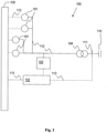
- Fig.1 shows a general layout of a wind park 100.
- the wind park 100 includes a plurality of wind turbines 101, a wind park controller 102, a compensation device 103, a wind park transformer 1044 and a wind park network 105.
- the wind park 100 is connected to a utility system or grid 110 via power lines 112 and through the wind park transformer 104.
- the interface point between the wind park 100 and the utility system 110 is called the point of common coupling (PCC) 111.
- PCC point of common coupling
- the compensation device 103 is a reactive power generation device used to compensate reactive power of the wind park 100.
- Examples of the compensation device 103 include but not limited to a thyristor switched capacitor bank and a static VAR compensator (SVC).
- SVC static VAR compensator
- the reactive power from the compensation device 103 is also delivered to the grid 110 over power lines 112.
- the wind park transformer 104 steps down the voltage from the wind park 100 into a lower voltage suitable for transmission in the grid 110.
- the wind park controller 102 generally fulfils a plurality of control functions.
- the power plant controller may collect different types of data which characterizes the current state of the wind turbines 101 or components thereof, and in response thereto control the operation of the wind turbines 101.
- the wind turbines 101 communicate with the controller 102 through the wind power plant network 105 using control lines 113 as shown as dotted lines in Fig.1 .
- the signals communicated between the controller 102 and the wind turbines 101 may include power output signal, turbine status, power reference, turbine command, etc.
- the controller 102 is also connected to the PCC 111 via control line 113. This allows the controller 102 to detect power parameters such as voltage and current levels at the PCC 111.
- the layout of the wind park 100 shown in Fig.1 is only an example, and the invention is not restricted to the exact layout of the wind park shown in Fig.1 .
- the wind park includes more or less than 4 wind turbines 101. It is also possible that the wind park only has 1 wind turbine 101. Similarly, the wind park 101 may include more than 1 compensation devices in other examples.
- Fig. 2a shows a graph illustrating a voltage level of the grid during a low voltage event.
- the vertical axis 201 shows the voltage level of the grid
- the horizontal axis 202 shows the time.
- the grid is stable, and the grid voltage is relatively constant as illustrated by 203.
- the grid voltage drops abruptly and drastically as illustrated by 204.
- the grid voltage may drop to about 10% (or 0.1 pu) of its original value in less than one millisecond.
- the grid voltage stays at the low value for a few hundred of miliseconds as illustrated by 205.
- the grid recovers and the grid voltage increases to about 80% of its original value in about 50-150 millisecond, as illustrated by 206.
- grid owners may specify in their grid codes that wind parks connected to the grid are required to inject certain amount of reactive current during a low voltage event. The amount of reactive current to be injected typically depends on the voltage level of the grid.
- Fig.2b shows a graph illustrating an example of the amount of reactive current required to be injected into the grid corresponding to the grid voltage level.
- the vertical axis 211 shows the required amount of reactive current to be injected
- the horizontal axis 212 shows the corresponding voltage level of the grid.
- the grid voltage is less than 0.5 pu
- the amount of reactive current is 0.9 pu as illustrated by 213.
- the grid voltage increases from 0.5 pu
- the amount of required reactive current decreases as shown by 214.
- the grid voltage recovers to 0.85 pu the amount of required reactive current to be injected into the grid is 0.
- the amount of reactive current generated by the wind turbines 101 and/or the compensation device 103 may not result in a desired reactive current at the PCC 111. This is because there are components and cables between the wind turbines 101 and/or the compensation device 103, and the PCC 111. Such components and cables introduce impedance into the transmission path, resulting in the reactive current reaching the PCC 111 to be different from that which was sent from the wind turbines 101 and the compensation device 103.
- the controller 102 determines an optimal reactive current to be provided at the PCC 111, that is, to be injected into the grid 110.
- the amount of reactive current to be injected into the grid 110 may be based on a pattern specified by grid owners, such as the pattern of Fig. 2b , or based on self-defined pattern.
- the controller 102 also determines a corresponding reactive and active current to be generated by the wind turbines 101 and/or the compensation device 103 in order to result in the optimal reactive current at the PCC 111.
- the active and reactive currents is determined taking into account any impedance between the wind turbines 101, the compensation device 103 and the PCC 111.
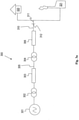
- Fig. 3a shows a schematic layout of the wind park 300 according to an embodiment.
- the schematic layout of Fig.3 illustrates the impedances that are introduced into the wind park 300.
- the wind park 300 may include more than one wind turbines 301. Is it also assumed that both the reactive and active current are generated by the wind turbine 301.
- the wind turbine 301 is connected to a wind turbine transformer 302.
- the wind turbine transformer 302 is in turn connected to the wind park transformer 304 via power cables 305.
- the impedance of the power cables 305 is represented by the cable impedance 303.
- the wind park 300 is connected to a utility system or grid 311 using overhead lines (OVL) 310.
- OTL overhead lines
- the impedance of the OVL 310 is represented by the OVL impedance 306.
- the wind park 300 interfaces with the grid 311 through the PCC 312.
- the grid 311 supplies power to a load, for example a household unit 320.
- Additional power plants for example a conventional coal power plant 321, may also supply power to the grid 311.
- the cable impedance 303 and the OVL impedance 306 are taken into account when determining the active and reactive currents to be generated, so as to provide the optimal reactive current at the PCC 312.
- Fig.3a may be further represented by the schematic diagram shown in Fig.3b .
- An example of determining an optimal active current to be generated by the wind turbine 301 in order to obtain the optimal reactive current at the PCC 312 will be illustrated with reference to Fig.3b .
- the impedance 331 between the wind turbine 301 and the PCC 312 is represented as Z.
- the impedance 332 from the PCC 312 to the grid fault is represented as Z F .
- the impedance 333 from the PCC 312 to the grid 311 is represented as Z G .
- I d ⁇ ⁇ v G K G E S X sin ⁇ + R cos ⁇ + 2 v G K G RE S K wf cos ⁇ + v G 2 K G 2 R + E S 2 K wf R K wf ⁇ 1 Z 2 v G 2 K G 2 + 2 v G K G K wf E S cos ⁇ + K wf 2 E S 2
- I q ⁇ v G K G E S R sin ⁇ + X cos ⁇ + 2 v G K G XE S K wf cos ⁇ + v G 2 K G 2 X + E S 2 K wf X K wf ⁇ 1 Z 2 v G 2 K G 2 + 2 v G K G K wf E S cos ⁇ + K wf 2 E S 2 .
- ⁇ opt arctan R X 2 K wf ⁇ 1 .
- I ds_opt R X I qs ⁇ v G K G Z 2 + 4 X 2 K wf 2 ⁇ K wf .
- the optimal active current I ds_opt can be approximated for an easier control implementation as: I ds _ opt ⁇ R X I qs ⁇ V PCC Z
- the reactive current I q at the PCC 312 is substantially influenced by the voltage level at the PCC 312, the impedance between the wind turbine 301 and the PCC 312 and the active current I d at the wind turbine 301.
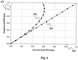
- Fig.4 shows the value of the reactive current I d at the PCC 312 with and without active current control according to an embodiment.
- the vertical axis 401 of the graph in Fig.4 is the reactive current value generated by the wind turbine, and the horizontal axis 402 is resulting reactive current value at the PCC 312.
- Curve 403 shows the value of the reactive current value at the PCC with respect to the reactive current generated by the wind turbine without any control of the active current generated by the wind turbine 301.
- Curve 404 shows the value of the reactive current value at the PCC with respect to the reactive current generated by the wind turbine when the active current generated by the wind turbine is controlled according to an embodiment. With active current control, it can be seen that the reactive current value at the PCC is maximized for any reactive current generated by the wind turbine.
- the active current and reactive current may be generated by other components outside the wind turbines.
- the reactive current may be generated from a STATCOM.
- the STATCOM may be located beside a wind turbine or at any other locations in a wind park.
- the active current may also be generated by an energy storage unit, such as a flow battery.
- the flow battery may be integrated into the wind turbine, or may be at any other locations in the wind park.
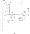
- Fig.5 shows a layout of the wind park 100 of Fig.1 where an energy storage unit 500 is used for generating active current to be provided at the PCC 111 of the wind park 100 according to an embodiment.
- the reactive current is generated by the compensation device 103, which may be a STATCOM.
- the PPC 102 sends control signals to the STATCOM 103 to generate the corresponding reactive current and to the energy storage unit 500 to generate the corresponding active current.
- the generation of the active current is controlled in order to maximize the reactive current at the PCC 111.
- the corresponding amount of reactive current to be generated in order to result in the desired amount of reactive current at the PCC 111 may be determined based on Fig.4 .
- the generated active and reactive currents are provided to the power lines or collector system 112 so that they result in the desired reactive current at the PCC 111. All the other components of the wind park 100 have been described with reference to Fig.1 .
- Fig.6 shows a flow-chart of a method for controlling a current in a wind park according to an embodiment.
- Step 601 of the method includes detecting a grid irregularity.
- the grid irregularity may be detected at the PCC 111 by the wind park controller 102 (see Fig.5 ).
- the grid irregularity to be detected may be a low voltage event.
- Step 602 includes determining an optimal current to be provided at a predetermined location in a wind park.
- the optimal current may be a reactive current to be provided at the PCC 111 of the wind park 100.
- the value of the reactive current to be provided may be required by grid owner (specified in grid codes) or self-defined.
- Step 603 includes determining a corresponding current to be generated so as to provide the optimal current at the predetermined location of the wind park.
- the corresponding current to be generated may be an active current and a reactive current. As described earlier, the generated active current may be controlled so as to provide the optimal reactive current provided at the PCC 111.
- the active and reactive currents may be generated by the wind turbine 101. Alternatively, the active current is generated by the wind turbine 101 and reactive current is generated by the STATCOM 500.
- the embodiments described above can also be used to control the generation of a reactive current so as to provide a desired active current at the PCC 111.
- the wind park controller 102 may send control signals to the wind turbines 101, the compensation device 103 and/or the energy storage unit 500 to generate corresponding active and reactive currents so as to provide the desired active current at the PCC 111 according to an embodiment.
- the generation of the corresponding reactive current is controlled in order to maximize the active current at the PCC 111.
Landscapes
- Engineering & Computer Science (AREA)
- Life Sciences & Earth Sciences (AREA)
- Sustainable Development (AREA)
- Sustainable Energy (AREA)
- Chemical & Material Sciences (AREA)
- Combustion & Propulsion (AREA)
- Mechanical Engineering (AREA)
- General Engineering & Computer Science (AREA)
- Power Engineering (AREA)
- Control Of Eletrric Generators (AREA)
- Wind Motors (AREA)
Claims (13)
- Verfahren zum Steuern eines Stroms in einem Windpark (100, 300), der mindestens eine Windkraftanlage (101, 301) umfasst, wobei der Windpark eine Vielzahl von Stromgeneratoren umfasst, wobei das Verfahren umfasst:Erkennen einer Netzunregelmäßigkeit;Bestimmen eines optimalen Stroms, der an einem vorbestimmten Standort im Windpark während der Netzunregelmäßigkeit bereitgestellt werden soll, wobei der vorbestimmte Standort ein Punkt der gemeinsamen Kopplung (111) des Windparks mit dem Netz ist; undBestimmen eines entsprechenden Stroms, der von der Vielzahl von Generatoren erzeugt werden soll, um den optimalen Strom an dem vorbestimmten Standort bereitzustellen, dadurch gekennzeichnet, dass der entsprechende Strom basierend auf mindestens einem Impedanzwert zwischen den Stromgeneratoren und dem vorbestimmten Standort bestimmt wird.
- Verfahren nach Anspruch 1, wobei der optimale Strom ein optimaler Blindstrom ist, wobei der optimale Blindstrom einem vorbestimmten Muster des eingespeisten Blindstroms in Richtung eines Spannungspegels während der Netzunregelmäßigkeit folgt.
- Verfahren nach einem der Ansprüche 1 oder 2, wobei mindestens einer der Vielzahl von Stromgeneratoren einen Blindstromgenerator zur Erzeugung eines Blindstroms und einen Wirkstromgenerator zur Erzeugung eines Wirkstroms umfasst.
- Verfahren nach Anspruch 3, weiter umfassend die Steuerung des vom Wirkstromgenerator zu erzeugenden Wirkstroms, um den optimalen Blindstrom an dem vorbestimmten Standort bereitzustellen.
- Verfahren nach Anspruch 4, wobei der Wirkstrom basierend auf dem folgenden Ausdruck bestimmt wird:
 Id_opt der Wirkstrom ist, der von dem mindestens einen Wirkstromgenerator erzeugt wird,Iqs der Blindstrom ist, der von dem mindestens einen Blindstromgenerator erzeugt wird,R ein Widerstand zwischen der Windkraftanlage und dem vorbestimmten Standort ist,Z die Impedanz zwischen der Windkraftanlage und dem vorbestimmten Standort ist,X eine reaktive Impedanz zwischen der Windkraftanlage und dem vorbestimmten Standort ist,νG die Amplitude der Spannung am Netz ist, undKG und Kwf Netzkonstanten sind.
 - Verfahren nach einem der Ansprüche 3-5, wobei der mindestens eine Blindstromgenerator einen statischen Synchronkompensator (STATCOM) umfasst.
- Verfahren nach einem der Ansprüche 3-6, wobei der mindestens eine Wirkstromgenerator eine Energiespeichereinheit umfasst.
- Windpark (100, 300), umfassend:- eine Vielzahl von Windkraftanlagen (101, 301); und- eine Windparksteuervorrichtung (102), die angepasst ist, Folgendes zu tun:- Erkennen einer Netzunregelmäßigkeit;- Bestimmen eines optimalen Stroms, der an einem vorbestimmten Standort im Windpark während der Netzunregelmäßigkeit bereitgestellt werden soll, wobei der vorbestimmte Standort ein Punkt der gemeinsamen Kopplung des Windparks mit dem Netz ist; und- Bestimmen eines entsprechenden Stroms, der aus einer Vielzahl von Stromgeneratoren erzeugt werden soll, um den optimalen Strom an dem vorbestimmten Standort bereitzustellen, wobei der entsprechende Strom basierend auf mindestens einem Impedanzwert zwischen dem Stromgenerator und dem vorbestimmten Standort bestimmt wird.
- Windpark nach Anspruch 8, wobei die Windparksteuervorrichtung (102) dazu angepasst ist, einen optimalen Blindstrom zu bestimmen, der an dem vorbestimmten Standort bereitgestellt werden soll, wobei der optimale Blindstrom einem vorbestimmten Muster von eingespeistem Blindstrom in Richtung eines Spannungspegels während der Netzunregelmäßigkeit folgt.
- Windpark nach einem der Ansprüche 8 oder 9, wobei mindestens einer der Vielzahl von Stromgeneratoren einen Blindstromgenerator zur Erzeugung eines Blindstroms und einen Wirkstromgenerator zur Erzeugung eines Wirkstroms umfasst.
- Windpark nach Anspruch 10, wobei die Windparksteuervorrichtung dazu angepasst ist, den von dem mindestens einen Wirkstromgenerator erzeugten Wirkstrom zu steuern, um den optimalen Blindstrom an dem vorbestimmten Standort bereitzustellen.
- Windpark nach einem der Ansprüche 10-11, weiter umfassend einen statischen Synchronkompensator (STATCOM), wobei der STATCOM der Blindstromgenerator des mindestens einen Stromgenerators zur Erzeugung des Blindstroms ist.
- Windpark nach einem der Ansprüche 10-12, weiter umfassend eine Energiespeichereinheit (500), wobei die Energiespeichereinheit der Wirkstromgenerator des mindestens einen Stromgenerators zum Erzeugen des Wirkstroms ist.
Applications Claiming Priority (2)
| Application Number | Priority Date | Filing Date | Title |
|---|---|---|---|
| DKPA200900781 | 2009-06-24 | ||
| US22213409P | 2009-07-01 | 2009-07-01 |
Publications (3)
| Publication Number | Publication Date |
|---|---|
| EP2267306A2 EP2267306A2 (de) | 2010-12-29 |
| EP2267306A3 EP2267306A3 (de) | 2014-10-08 |
| EP2267306B1 true EP2267306B1 (de) | 2022-03-23 |
Family
ID=42224619
Family Applications (1)
| Application Number | Title | Priority Date | Filing Date |
|---|---|---|---|
| EP10162103.5A Active EP2267306B1 (de) | 2009-06-24 | 2010-05-06 | Stromsteuerung für einen Windpark |
Country Status (3)
| Country | Link |
|---|---|
| US (1) | US8655495B2 (de) |
| EP (1) | EP2267306B1 (de) |
| CN (1) | CN101929439B (de) |
Families Citing this family (33)
| Publication number | Priority date | Publication date | Assignee | Title |
|---|---|---|---|---|
| ES2320401B1 (es) * | 2007-11-20 | 2010-02-26 | Acciona Windpower S.A. | Parque eolico. |
| US7948103B2 (en) * | 2009-09-03 | 2011-05-24 | General Electric Company | Method and system for verifying wind turbine operation |
| US9300142B2 (en) * | 2010-01-26 | 2016-03-29 | Vestas Wind Systems A/S | Method for emulation of synchronous machine |
| WO2012000517A2 (en) * | 2010-06-30 | 2012-01-05 | Vestas Wind Systems A/S | Operating a wind power plant including energy storage during grid faults |
| CN103154509B (zh) * | 2010-08-23 | 2016-03-16 | 维斯塔斯风力系统集团公司 | 运行风力涡轮机的方法和风力涡轮机 |
| CN103141004B (zh) * | 2010-09-22 | 2016-12-07 | 东芝三菱电机产业系统株式会社 | 电力转换装置 |
| DK2485358T4 (da) * | 2011-02-07 | 2022-01-10 | Siemens Gamesa Renewable Energy As | System og fremgangsmåde til at dæmpe en elektrisk ubalance af en trefasestrøm ved et fælles koblingspunkt mellem en vindmøllepark og et forsyningsnet |
| DE102011112025A1 (de) | 2011-08-31 | 2013-02-28 | Repower Systems Se | Schnelle Spannungsregelung |
| WO2013037846A1 (en) * | 2011-09-12 | 2013-03-21 | Alstom Technology Ltd | Sub-synchronous oscillation damping by shunt facts apparatus |
| US9835136B2 (en) | 2011-09-26 | 2017-12-05 | Vestas Wind Systems A/S | System and method for extending the operating life of a wind turbine gear train based on energy storage |
| WO2013046193A2 (en) * | 2011-09-26 | 2013-04-04 | Vestas Wind Systems A/S | System and method for extending the operating life of a wind turbine gear train based on energy storage |
| US20130138257A1 (en) * | 2011-11-30 | 2013-05-30 | Thomas Edenfeld | System for operating an electric power system and method of operating the same |
| JP5702000B2 (ja) * | 2012-01-06 | 2015-04-15 | 株式会社日立製作所 | 電力系統安定化システム及び電力系統安定化方法 |
| JP5734516B2 (ja) * | 2012-05-31 | 2015-06-17 | 三菱重工業株式会社 | 電圧制御装置、その制御方法およびその電圧制御プログラム |
| EP2859638B1 (de) | 2012-06-12 | 2020-05-06 | Vestas Wind Systems A/S | Steuerung einer windkraftanlage nach niederspannungsnetzdefekten |
| US9190845B2 (en) * | 2012-07-17 | 2015-11-17 | Siemens Aktiengesellschaft | Method and apparatus for adaptively controlling wind park turbines |
| EP2793392B1 (de) * | 2013-04-16 | 2023-07-12 | Siemens Aktiengesellschaft | Steuergerät zur Steuerung eines Stromwandlers |
| DE102013210812A1 (de) * | 2013-06-10 | 2014-12-11 | Wobben Properties Gmbh | Verfahren zum Einspeisen elektrischer Leistung in ein elektrisches Versorgungsnetz |
| US9541062B2 (en) * | 2013-11-20 | 2017-01-10 | Siemens Aktiengesellschaft | Method of operating a wind park |
| ES2710387T3 (es) * | 2013-11-28 | 2019-04-24 | Vestas Wind Sys As | Reconfiguración del bucle de potencia reactiva de una instalación de energía eólica |
| WO2015086022A1 (en) * | 2013-12-11 | 2015-06-18 | Vestas Wind Systems A/S | A wind power plant, and a method for controlling a reactive current injection in a wind power plant |
| GB2521414B (en) * | 2013-12-19 | 2016-01-27 | Univ Cape Town | Optimal currents for power injection or extraction in a power network |
| ES2811843T3 (es) * | 2014-10-24 | 2021-03-15 | Vestas Wind Sys As | Método para operar una planta de energía eólica en un entorno de red de distribución débil y una planta de energía eólica |
| US9970417B2 (en) | 2016-04-14 | 2018-05-15 | General Electric Company | Wind converter control for weak grid |
| CN111095715B (zh) * | 2017-09-13 | 2023-11-07 | 维斯塔斯风力系统集团公司 | 涉及风力发电厂内的电压控制的改进 |
| FR3071620B1 (fr) * | 2017-09-26 | 2020-10-02 | Ge Energy Power Conversion Technology Ltd | Dispositif et procede de test de modules de puissance |
| WO2019120400A1 (en) * | 2017-12-21 | 2019-06-27 | Vestas Wind Systems A/S | Improvements relating to current injection in wind power plants |
| WO2020125882A1 (en) | 2018-12-20 | 2020-06-25 | Vestas Wind Systems A/S | Boosting reactive current injection from wind turbine generators |
| US10790668B1 (en) * | 2019-05-06 | 2020-09-29 | General Electric Company | Method for reactive power oscillation damping for a wind turbine system with integrated reactive power compensation device |
| US11056884B2 (en) | 2019-05-06 | 2021-07-06 | General Electric Company | Wind turbine system with integrated reactive power compensation device |
| EP3832128A1 (de) * | 2019-12-03 | 2021-06-09 | Wobben Properties GmbH | Verfahren zum steuern eines windparks |
| EP4111569A1 (de) | 2020-02-26 | 2023-01-04 | Vestas Wind Systems A/S | Verfahren zum steuern einer kraftwerksanlage für erneuerbare energie während spannungsereignissen |
| CN111342473A (zh) * | 2020-03-03 | 2020-06-26 | 国网江西省电力有限公司电力科学研究院 | 一种高压链式statcom功率模块自适应温度控制方法 |
Citations (3)
| Publication number | Priority date | Publication date | Assignee | Title |
|---|---|---|---|---|
| WO2004040748A1 (en) * | 2002-11-01 | 2004-05-13 | Vestas Wind Systems A/S | Circuit arrangement for use in a variable speed wind turbine system comprising a double-fed induction generator and a back-to-back converter |
| US20080073912A1 (en) * | 2004-10-01 | 2008-03-27 | Repower Systems Ag | Wind Park with Robust Reactive Power Adjustment System and Method for the Operation Thereof |
| DE102007017870A1 (de) * | 2007-04-13 | 2008-10-16 | Repower Systems Ag | Verfahren zum Betreiben einer Windenergieanlage bei Überspannungen im Netz |
Family Cites Families (27)
| Publication number | Priority date | Publication date | Assignee | Title |
|---|---|---|---|---|
| US5083039B1 (en) * | 1991-02-01 | 1999-11-16 | Zond Energy Systems Inc | Variable speed wind turbine |
| US5187427A (en) * | 1991-11-27 | 1993-02-16 | U.S. Windpower, Inc. | Static reactive power compensator |
| CN1426510A (zh) * | 2000-03-08 | 2003-06-25 | 里索国家实验室 | 一种操作涡轮机的方法 |
| US6670721B2 (en) * | 2001-07-10 | 2003-12-30 | Abb Ab | System, method, rotating machine and computer program product for enhancing electric power produced by renewable facilities |
| EP2267859A3 (de) * | 2001-07-23 | 2014-08-13 | Northern Power Systems Utility Scale, Inc. | Steuersystem für einen Leistungswandler und Verfahren zur Steuerung des Betriebs eines Leistungswandlers |
| US7015595B2 (en) * | 2002-02-11 | 2006-03-21 | Vestas Wind Systems A/S | Variable speed wind turbine having a passive grid side rectifier with scalar power control and dependent pitch control |
| CA2515436C (en) * | 2003-02-07 | 2012-04-10 | Vestas Wind Systems A/S | Method for controlling a power-grid connected wind turbine generator during grid faults and apparatus for implementing said method |
| US6924565B2 (en) | 2003-08-18 | 2005-08-02 | General Electric Company | Continuous reactive power support for wind turbine generators |
| CN1926742B (zh) * | 2004-03-12 | 2011-05-25 | 通用电气公司 | 用于操作发电机变频器的方法以及具有根据这种方法操作的发电机的风能涡轮机 |
| EP1883880A4 (de) * | 2005-05-24 | 2010-05-05 | Satcon Technology Corp | Vorrichtung, system und verfahren zur bereitstellung eines niedrigspannungs-fehlerdurchlaufs für eine windgeneratorfarm |
| US7372174B2 (en) * | 2005-11-11 | 2008-05-13 | Converteam Ltd | Power converters |
| US7511385B2 (en) * | 2005-11-11 | 2009-03-31 | Converteam Ltd | Power converters |
| US7253537B2 (en) * | 2005-12-08 | 2007-08-07 | General Electric Company | System and method of operating double fed induction generators |
| US7508173B2 (en) * | 2005-12-08 | 2009-03-24 | General Electric Company | System and method for providing reactive power support with distributed energy resource inverter |
| US7567160B2 (en) * | 2006-02-15 | 2009-07-28 | American Superconductor Corporation | Supplementary transformer cooling in a reactive power compensation system |
| US7505833B2 (en) | 2006-03-29 | 2009-03-17 | General Electric Company | System, method, and article of manufacture for controlling operation of an electrical power generation system |
| MX2009001796A (es) * | 2006-09-01 | 2009-04-06 | Vestas Wind Sys As | Sistema y metodo para controlar una turbina eolica en una central de energia eólica. |
| DE102006047503A1 (de) * | 2006-10-05 | 2008-04-10 | Repower Systems Ag | Verfahren zum Betreiben sowie Verwendung eines Umrichters |
| US7417333B2 (en) * | 2006-11-02 | 2008-08-26 | General Electric Company | Methods and apparatus for controlling current in an electrical machine |
| JP2008301584A (ja) * | 2007-05-30 | 2008-12-11 | Hitachi Ltd | 風力発電システムおよび電力変換器の制御方法 |
| DE102008007448A1 (de) * | 2008-02-01 | 2009-08-13 | Woodward Seg Gmbh & Co. Kg | Verfahren zum Betreiben einer Windenergieanlage |
| US7994658B2 (en) * | 2008-02-28 | 2011-08-09 | General Electric Company | Windfarm collector system loss optimization |
| CN101272055B (zh) * | 2008-05-07 | 2011-11-16 | 中国科学院电工研究所 | 一种风力发电机组低电压穿越控制方法 |
| US7839024B2 (en) * | 2008-07-29 | 2010-11-23 | General Electric Company | Intra-area master reactive controller for tightly coupled windfarms |
| US8041465B2 (en) * | 2008-10-09 | 2011-10-18 | General Electric Company | Voltage control at windfarms |
| CN101383576B (zh) * | 2008-10-28 | 2010-12-29 | 华北电力大学(保定) | 一种大型风力发电机组穿越电网低电压故障的方法 |
| US7804184B2 (en) * | 2009-01-23 | 2010-09-28 | General Electric Company | System and method for control of a grid connected power generating system |
-
2010
- 2010-04-30 US US12/771,724 patent/US8655495B2/en active Active
- 2010-05-06 EP EP10162103.5A patent/EP2267306B1/de active Active
- 2010-05-26 CN CN201010190335.6A patent/CN101929439B/zh active Active
Patent Citations (3)
| Publication number | Priority date | Publication date | Assignee | Title |
|---|---|---|---|---|
| WO2004040748A1 (en) * | 2002-11-01 | 2004-05-13 | Vestas Wind Systems A/S | Circuit arrangement for use in a variable speed wind turbine system comprising a double-fed induction generator and a back-to-back converter |
| US20080073912A1 (en) * | 2004-10-01 | 2008-03-27 | Repower Systems Ag | Wind Park with Robust Reactive Power Adjustment System and Method for the Operation Thereof |
| DE102007017870A1 (de) * | 2007-04-13 | 2008-10-16 | Repower Systems Ag | Verfahren zum Betreiben einer Windenergieanlage bei Überspannungen im Netz |
Also Published As
| Publication number | Publication date |
|---|---|
| EP2267306A3 (de) | 2014-10-08 |
| US8655495B2 (en) | 2014-02-18 |
| EP2267306A2 (de) | 2010-12-29 |
| CN101929439B (zh) | 2014-09-24 |
| US20100332040A1 (en) | 2010-12-30 |
| CN101929439A (zh) | 2010-12-29 |
Similar Documents
| Publication | Publication Date | Title |
|---|---|---|
| EP2267306B1 (de) | Stromsteuerung für einen Windpark | |
| US10063059B2 (en) | Wind power plant with optimal power output | |
| AU2012213941B2 (en) | Method for operating a wind farm, wind farm controller and wind farm | |
| Qiao et al. | Grid connection requirements and solutions for DFIG wind turbines | |
| EP1561946B1 (de) | Elektrischer netzfehlertoleranter Generator | |
| EP2114007B1 (de) | Stromversorgungs-System mit netzfehlertoleranter Fähigkeit | |
| US9932966B2 (en) | Method for avoiding voltage instability in an electrical grid of an offshore wind park | |
| CN117239779A (zh) | 电网形成基于逆变器的资源的系统级过载穿越控制策略 | |
| KR20120083848A (ko) | 풍력 발전 설비의 출력 제어 방법 및 출력 제어 장치 | |
| US11336098B2 (en) | Interconnection of multiple renewable energy power plants | |
| CN117318132A (zh) | 用于改善电网稳定性的方法和系统 | |
| Pokharel et al. | Mitigation of disturbances in DFIG-based wind farm connected to weak distribution system using STATCOM | |
| WO2019034215A1 (en) | IMPROVEMENTS RELATING TO REACTIVE POWER CONTROL IN WIND POWER PLANTS | |
| Gurugubelli et al. | A new hybrid islanding detection technique for microgrid using virtual synchronous machine | |
| Zhou et al. | A multi-level coordinated DC overcurrent suppression scheme for symmetrical bipolar MMC-HVDC integrated offshore wind farms | |
| Nawir | Integration of wind farms into weak AC grid | |
| Pereira et al. | STATCOM to improve the voltage stability of an electric power system with high penetration of wind generation | |
| Ouyang et al. | An improved control method of fault ride-through for DPMWT-based wind farm considering coupling effect of HVDC transmission system | |
| Sarrias et al. | Comparative study of the behavior of a wind farm integrating three different FACTS devices | |
| CN106130074A (zh) | 一种基于svg设备的提高风电场低电压穿越能力的方法 | |
| Dicorato et al. | Voltage compensation for wind integration in power systems | |
| Ko | Supervisory voltage control scheme for grid-connected wind farms | |
| Jadeja et al. | Synthetic/virtual Inertia in Renewable Energy Sourced Grid: A Review | |
| Niu et al. | Low Voltage Ride-through Strategy for Wind Farm and VSC-HVDC | |
| Wang et al. | Research on cooperative fault ride-through strategy of offshore wind power grid-connected system via VSC-HVDC system |
Legal Events
| Date | Code | Title | Description |
|---|---|---|---|
| PUAI | Public reference made under article 153(3) epc to a published international application that has entered the european phase |
Free format text: ORIGINAL CODE: 0009012 |
|
| AK | Designated contracting states |
Kind code of ref document: A2 Designated state(s): AL AT BE BG CH CY CZ DE DK EE ES FI FR GB GR HR HU IE IS IT LI LT LU LV MC MK MT NL NO PL PT RO SE SI SK SM TR |
|
| AX | Request for extension of the european patent |
Extension state: BA ME RS |
|
| RAP1 | Party data changed (applicant data changed or rights of an application transferred) |
Owner name: VESTAS WIND SYSTEMS A/S |
|
| PUAL | Search report despatched |
Free format text: ORIGINAL CODE: 0009013 |
|
| AK | Designated contracting states |
Kind code of ref document: A3 Designated state(s): AL AT BE BG CH CY CZ DE DK EE ES FI FR GB GR HR HU IE IS IT LI LT LU LV MC MK MT NL NO PL PT RO SE SI SK SM TR |
|
| AX | Request for extension of the european patent |
Extension state: BA ME RS |
|
| RIC1 | Information provided on ipc code assigned before grant |
Ipc: F03D 9/00 20060101AFI20140901BHEP |
|
| 17P | Request for examination filed |
Effective date: 20150311 |
|
| RBV | Designated contracting states (corrected) |
Designated state(s): AL AT BE BG CH CY CZ DE DK EE ES FI FR GB GR HR HU IE IS IT LI LT LU LV MC MK MT NL NO PL PT RO SE SI SK SM TR |
|
| RAP1 | Party data changed (applicant data changed or rights of an application transferred) |
Owner name: VESTAS WIND SYSTEMS A/S |
|
| STAA | Information on the status of an ep patent application or granted ep patent |
Free format text: STATUS: EXAMINATION IS IN PROGRESS |
|
| 17Q | First examination report despatched |
Effective date: 20170329 |
|
| GRAP | Despatch of communication of intention to grant a patent |
Free format text: ORIGINAL CODE: EPIDOSNIGR1 |
|
| STAA | Information on the status of an ep patent application or granted ep patent |
Free format text: STATUS: GRANT OF PATENT IS INTENDED |
|
| RIC1 | Information provided on ipc code assigned before grant |
Ipc: F03D 7/04 20060101ALI20211025BHEP Ipc: F03D 7/02 20060101ALI20211025BHEP Ipc: F03D 9/00 20160101AFI20211025BHEP |
|
| INTG | Intention to grant announced |
Effective date: 20211112 |
|
| GRAS | Grant fee paid |
Free format text: ORIGINAL CODE: EPIDOSNIGR3 |
|
| GRAA | (expected) grant |
Free format text: ORIGINAL CODE: 0009210 |
|
| STAA | Information on the status of an ep patent application or granted ep patent |
Free format text: STATUS: THE PATENT HAS BEEN GRANTED |
|
| AK | Designated contracting states |
Kind code of ref document: B1 Designated state(s): AL AT BE BG CH CY CZ DE DK EE ES FI FR GB GR HR HU IE IS IT LI LT LU LV MC MK MT NL NO PL PT RO SE SI SK SM TR |
|
| REG | Reference to a national code |
Ref country code: GB Ref legal event code: FG4D |
|
| REG | Reference to a national code |
Ref country code: CH Ref legal event code: EP |
|
| REG | Reference to a national code |
Ref country code: IE Ref legal event code: FG4D |
|
| REG | Reference to a national code |
Ref country code: DE Ref legal event code: R096 Ref document number: 602010068127 Country of ref document: DE |
|
| REG | Reference to a national code |
Ref country code: AT Ref legal event code: REF Ref document number: 1477596 Country of ref document: AT Kind code of ref document: T Effective date: 20220415 |
|
| REG | Reference to a national code |
Ref country code: LT Ref legal event code: MG9D |
|
| REG | Reference to a national code |
Ref country code: NL Ref legal event code: MP Effective date: 20220323 |
|
| PG25 | Lapsed in a contracting state [announced via postgrant information from national office to epo] |
Ref country code: SE Free format text: LAPSE BECAUSE OF FAILURE TO SUBMIT A TRANSLATION OF THE DESCRIPTION OR TO PAY THE FEE WITHIN THE PRESCRIBED TIME-LIMIT Effective date: 20220323 Ref country code: NO Free format text: LAPSE BECAUSE OF FAILURE TO SUBMIT A TRANSLATION OF THE DESCRIPTION OR TO PAY THE FEE WITHIN THE PRESCRIBED TIME-LIMIT Effective date: 20220623 Ref country code: LT Free format text: LAPSE BECAUSE OF FAILURE TO SUBMIT A TRANSLATION OF THE DESCRIPTION OR TO PAY THE FEE WITHIN THE PRESCRIBED TIME-LIMIT Effective date: 20220323 Ref country code: HR Free format text: LAPSE BECAUSE OF FAILURE TO SUBMIT A TRANSLATION OF THE DESCRIPTION OR TO PAY THE FEE WITHIN THE PRESCRIBED TIME-LIMIT Effective date: 20220323 Ref country code: BG Free format text: LAPSE BECAUSE OF FAILURE TO SUBMIT A TRANSLATION OF THE DESCRIPTION OR TO PAY THE FEE WITHIN THE PRESCRIBED TIME-LIMIT Effective date: 20220623 |
|
| REG | Reference to a national code |
Ref country code: AT Ref legal event code: MK05 Ref document number: 1477596 Country of ref document: AT Kind code of ref document: T Effective date: 20220323 |
|
| PG25 | Lapsed in a contracting state [announced via postgrant information from national office to epo] |
Ref country code: LV Free format text: LAPSE BECAUSE OF FAILURE TO SUBMIT A TRANSLATION OF THE DESCRIPTION OR TO PAY THE FEE WITHIN THE PRESCRIBED TIME-LIMIT Effective date: 20220323 Ref country code: GR Free format text: LAPSE BECAUSE OF FAILURE TO SUBMIT A TRANSLATION OF THE DESCRIPTION OR TO PAY THE FEE WITHIN THE PRESCRIBED TIME-LIMIT Effective date: 20220624 Ref country code: FI Free format text: LAPSE BECAUSE OF FAILURE TO SUBMIT A TRANSLATION OF THE DESCRIPTION OR TO PAY THE FEE WITHIN THE PRESCRIBED TIME-LIMIT Effective date: 20220323 |
|
| PG25 | Lapsed in a contracting state [announced via postgrant information from national office to epo] |
Ref country code: NL Free format text: LAPSE BECAUSE OF FAILURE TO SUBMIT A TRANSLATION OF THE DESCRIPTION OR TO PAY THE FEE WITHIN THE PRESCRIBED TIME-LIMIT Effective date: 20220323 |
|
| PG25 | Lapsed in a contracting state [announced via postgrant information from national office to epo] |
Ref country code: SM Free format text: LAPSE BECAUSE OF FAILURE TO SUBMIT A TRANSLATION OF THE DESCRIPTION OR TO PAY THE FEE WITHIN THE PRESCRIBED TIME-LIMIT Effective date: 20220323 Ref country code: SK Free format text: LAPSE BECAUSE OF FAILURE TO SUBMIT A TRANSLATION OF THE DESCRIPTION OR TO PAY THE FEE WITHIN THE PRESCRIBED TIME-LIMIT Effective date: 20220323 Ref country code: RO Free format text: LAPSE BECAUSE OF FAILURE TO SUBMIT A TRANSLATION OF THE DESCRIPTION OR TO PAY THE FEE WITHIN THE PRESCRIBED TIME-LIMIT Effective date: 20220323 Ref country code: PT Free format text: LAPSE BECAUSE OF FAILURE TO SUBMIT A TRANSLATION OF THE DESCRIPTION OR TO PAY THE FEE WITHIN THE PRESCRIBED TIME-LIMIT Effective date: 20220725 Ref country code: ES Free format text: LAPSE BECAUSE OF FAILURE TO SUBMIT A TRANSLATION OF THE DESCRIPTION OR TO PAY THE FEE WITHIN THE PRESCRIBED TIME-LIMIT Effective date: 20220323 Ref country code: EE Free format text: LAPSE BECAUSE OF FAILURE TO SUBMIT A TRANSLATION OF THE DESCRIPTION OR TO PAY THE FEE WITHIN THE PRESCRIBED TIME-LIMIT Effective date: 20220323 Ref country code: CZ Free format text: LAPSE BECAUSE OF FAILURE TO SUBMIT A TRANSLATION OF THE DESCRIPTION OR TO PAY THE FEE WITHIN THE PRESCRIBED TIME-LIMIT Effective date: 20220323 Ref country code: AT Free format text: LAPSE BECAUSE OF FAILURE TO SUBMIT A TRANSLATION OF THE DESCRIPTION OR TO PAY THE FEE WITHIN THE PRESCRIBED TIME-LIMIT Effective date: 20220323 |
|
| PG25 | Lapsed in a contracting state [announced via postgrant information from national office to epo] |
Ref country code: PL Free format text: LAPSE BECAUSE OF FAILURE TO SUBMIT A TRANSLATION OF THE DESCRIPTION OR TO PAY THE FEE WITHIN THE PRESCRIBED TIME-LIMIT Effective date: 20220323 Ref country code: IS Free format text: LAPSE BECAUSE OF FAILURE TO SUBMIT A TRANSLATION OF THE DESCRIPTION OR TO PAY THE FEE WITHIN THE PRESCRIBED TIME-LIMIT Effective date: 20220723 Ref country code: AL Free format text: LAPSE BECAUSE OF FAILURE TO SUBMIT A TRANSLATION OF THE DESCRIPTION OR TO PAY THE FEE WITHIN THE PRESCRIBED TIME-LIMIT Effective date: 20220323 |
|
| REG | Reference to a national code |
Ref country code: CH Ref legal event code: PL |
|
| REG | Reference to a national code |
Ref country code: DE Ref legal event code: R097 Ref document number: 602010068127 Country of ref document: DE |
|
| REG | Reference to a national code |
Ref country code: BE Ref legal event code: MM Effective date: 20220531 |
|
| PLBE | No opposition filed within time limit |
Free format text: ORIGINAL CODE: 0009261 |
|
| STAA | Information on the status of an ep patent application or granted ep patent |
Free format text: STATUS: NO OPPOSITION FILED WITHIN TIME LIMIT |
|
| PG25 | Lapsed in a contracting state [announced via postgrant information from national office to epo] |
Ref country code: MC Free format text: LAPSE BECAUSE OF FAILURE TO SUBMIT A TRANSLATION OF THE DESCRIPTION OR TO PAY THE FEE WITHIN THE PRESCRIBED TIME-LIMIT Effective date: 20220323 Ref country code: LU Free format text: LAPSE BECAUSE OF NON-PAYMENT OF DUE FEES Effective date: 20220506 Ref country code: LI Free format text: LAPSE BECAUSE OF NON-PAYMENT OF DUE FEES Effective date: 20220531 Ref country code: DK Free format text: LAPSE BECAUSE OF FAILURE TO SUBMIT A TRANSLATION OF THE DESCRIPTION OR TO PAY THE FEE WITHIN THE PRESCRIBED TIME-LIMIT Effective date: 20220323 Ref country code: CH Free format text: LAPSE BECAUSE OF NON-PAYMENT OF DUE FEES Effective date: 20220531 |
|
| 26N | No opposition filed |
Effective date: 20230102 |
|
| PG25 | Lapsed in a contracting state [announced via postgrant information from national office to epo] |
Ref country code: IE Free format text: LAPSE BECAUSE OF NON-PAYMENT OF DUE FEES Effective date: 20220506 |
|
| PG25 | Lapsed in a contracting state [announced via postgrant information from national office to epo] |
Ref country code: SI Free format text: LAPSE BECAUSE OF FAILURE TO SUBMIT A TRANSLATION OF THE DESCRIPTION OR TO PAY THE FEE WITHIN THE PRESCRIBED TIME-LIMIT Effective date: 20220323 Ref country code: BE Free format text: LAPSE BECAUSE OF NON-PAYMENT OF DUE FEES Effective date: 20220531 |
|
| P01 | Opt-out of the competence of the unified patent court (upc) registered |
Effective date: 20230521 |
|
| PG25 | Lapsed in a contracting state [announced via postgrant information from national office to epo] |
Ref country code: IT Free format text: LAPSE BECAUSE OF FAILURE TO SUBMIT A TRANSLATION OF THE DESCRIPTION OR TO PAY THE FEE WITHIN THE PRESCRIBED TIME-LIMIT Effective date: 20220323 |
|
| PG25 | Lapsed in a contracting state [announced via postgrant information from national office to epo] |
Ref country code: HU Free format text: LAPSE BECAUSE OF FAILURE TO SUBMIT A TRANSLATION OF THE DESCRIPTION OR TO PAY THE FEE WITHIN THE PRESCRIBED TIME-LIMIT; INVALID AB INITIO Effective date: 20100506 |
|
| PG25 | Lapsed in a contracting state [announced via postgrant information from national office to epo] |
Ref country code: MK Free format text: LAPSE BECAUSE OF FAILURE TO SUBMIT A TRANSLATION OF THE DESCRIPTION OR TO PAY THE FEE WITHIN THE PRESCRIBED TIME-LIMIT Effective date: 20220323 Ref country code: CY Free format text: LAPSE BECAUSE OF FAILURE TO SUBMIT A TRANSLATION OF THE DESCRIPTION OR TO PAY THE FEE WITHIN THE PRESCRIBED TIME-LIMIT Effective date: 20220323 |
|
| PG25 | Lapsed in a contracting state [announced via postgrant information from national office to epo] |
Ref country code: TR Free format text: LAPSE BECAUSE OF FAILURE TO SUBMIT A TRANSLATION OF THE DESCRIPTION OR TO PAY THE FEE WITHIN THE PRESCRIBED TIME-LIMIT Effective date: 20220323 |
|
| PG25 | Lapsed in a contracting state [announced via postgrant information from national office to epo] |
Ref country code: MT Free format text: LAPSE BECAUSE OF FAILURE TO SUBMIT A TRANSLATION OF THE DESCRIPTION OR TO PAY THE FEE WITHIN THE PRESCRIBED TIME-LIMIT Effective date: 20220323 |
|
| PGFP | Annual fee paid to national office [announced via postgrant information from national office to epo] |
Ref country code: DE Payment date: 20250528 Year of fee payment: 16 |
|
| PGFP | Annual fee paid to national office [announced via postgrant information from national office to epo] |
Ref country code: GB Payment date: 20250520 Year of fee payment: 16 |
|
| PGFP | Annual fee paid to national office [announced via postgrant information from national office to epo] |
Ref country code: FR Payment date: 20250526 Year of fee payment: 16 |