EP2266837B1 - Light distribution control system for automotive headlamp - Google Patents
Light distribution control system for automotive headlamp Download PDFInfo
- Publication number
- EP2266837B1 EP2266837B1 EP10166812A EP10166812A EP2266837B1 EP 2266837 B1 EP2266837 B1 EP 2266837B1 EP 10166812 A EP10166812 A EP 10166812A EP 10166812 A EP10166812 A EP 10166812A EP 2266837 B1 EP2266837 B1 EP 2266837B1
- Authority
- EP
- European Patent Office
- Prior art keywords
- light distribution
- distribution pattern
- vehicle
- leading vehicle
- switching
- Prior art date
- Legal status (The legal status is an assumption and is not a legal conclusion. Google has not performed a legal analysis and makes no representation as to the accuracy of the status listed.)
- Active
Links
Images


Classifications
-
- B—PERFORMING OPERATIONS; TRANSPORTING
- B60—VEHICLES IN GENERAL
- B60Q—ARRANGEMENT OF SIGNALLING OR LIGHTING DEVICES, THE MOUNTING OR SUPPORTING THEREOF OR CIRCUITS THEREFOR, FOR VEHICLES IN GENERAL
- B60Q1/00—Arrangement of optical signalling or lighting devices, the mounting or supporting thereof or circuits therefor
- B60Q1/02—Arrangement of optical signalling or lighting devices, the mounting or supporting thereof or circuits therefor the devices being primarily intended to illuminate the way ahead or to illuminate other areas of way or environments
- B60Q1/04—Arrangement of optical signalling or lighting devices, the mounting or supporting thereof or circuits therefor the devices being primarily intended to illuminate the way ahead or to illuminate other areas of way or environments the devices being headlights
- B60Q1/14—Arrangement of optical signalling or lighting devices, the mounting or supporting thereof or circuits therefor the devices being primarily intended to illuminate the way ahead or to illuminate other areas of way or environments the devices being headlights having dimming means
- B60Q1/1415—Dimming circuits
- B60Q1/1423—Automatic dimming circuits, i.e. switching between high beam and low beam due to change of ambient light or light level in road traffic
-
- F—MECHANICAL ENGINEERING; LIGHTING; HEATING; WEAPONS; BLASTING
- F21—LIGHTING
- F21S—NON-PORTABLE LIGHTING DEVICES; SYSTEMS THEREOF; VEHICLE LIGHTING DEVICES SPECIALLY ADAPTED FOR VEHICLE EXTERIORS
- F21S41/00—Illuminating devices specially adapted for vehicle exteriors, e.g. headlamps
- F21S41/60—Illuminating devices specially adapted for vehicle exteriors, e.g. headlamps characterised by a variable light distribution
- F21S41/68—Illuminating devices specially adapted for vehicle exteriors, e.g. headlamps characterised by a variable light distribution by acting on screens
- F21S41/683—Illuminating devices specially adapted for vehicle exteriors, e.g. headlamps characterised by a variable light distribution by acting on screens by moving screens
- F21S41/698—Shaft-shaped screens rotating along its longitudinal axis
-
- G—PHYSICS
- G06—COMPUTING; CALCULATING OR COUNTING
- G06V—IMAGE OR VIDEO RECOGNITION OR UNDERSTANDING
- G06V20/00—Scenes; Scene-specific elements
- G06V20/50—Context or environment of the image
- G06V20/56—Context or environment of the image exterior to a vehicle by using sensors mounted on the vehicle
- G06V20/58—Recognition of moving objects or obstacles, e.g. vehicles or pedestrians; Recognition of traffic objects, e.g. traffic signs, traffic lights or roads
-
- H—ELECTRICITY
- H05—ELECTRIC TECHNIQUES NOT OTHERWISE PROVIDED FOR
- H05B—ELECTRIC HEATING; ELECTRIC LIGHT SOURCES NOT OTHERWISE PROVIDED FOR; CIRCUIT ARRANGEMENTS FOR ELECTRIC LIGHT SOURCES, IN GENERAL
- H05B47/00—Circuit arrangements for operating light sources in general, i.e. where the type of light source is not relevant
- H05B47/10—Controlling the light source
-
- B—PERFORMING OPERATIONS; TRANSPORTING
- B60—VEHICLES IN GENERAL
- B60Q—ARRANGEMENT OF SIGNALLING OR LIGHTING DEVICES, THE MOUNTING OR SUPPORTING THEREOF OR CIRCUITS THEREFOR, FOR VEHICLES IN GENERAL
- B60Q2300/00—Indexing codes for automatically adjustable headlamps or automatically dimmable headlamps
- B60Q2300/05—Special features for controlling or switching of the light beam
- B60Q2300/056—Special anti-blinding beams, e.g. a standard beam is chopped or moved in order not to blind
-
- B—PERFORMING OPERATIONS; TRANSPORTING
- B60—VEHICLES IN GENERAL
- B60Q—ARRANGEMENT OF SIGNALLING OR LIGHTING DEVICES, THE MOUNTING OR SUPPORTING THEREOF OR CIRCUITS THEREFOR, FOR VEHICLES IN GENERAL
- B60Q2300/00—Indexing codes for automatically adjustable headlamps or automatically dimmable headlamps
- B60Q2300/30—Indexing codes relating to the vehicle environment
- B60Q2300/31—Atmospheric conditions
- B60Q2300/312—Adverse weather
-
- B—PERFORMING OPERATIONS; TRANSPORTING
- B60—VEHICLES IN GENERAL
- B60Q—ARRANGEMENT OF SIGNALLING OR LIGHTING DEVICES, THE MOUNTING OR SUPPORTING THEREOF OR CIRCUITS THEREFOR, FOR VEHICLES IN GENERAL
- B60Q2300/00—Indexing codes for automatically adjustable headlamps or automatically dimmable headlamps
- B60Q2300/30—Indexing codes relating to the vehicle environment
- B60Q2300/32—Road surface or travel path
- B60Q2300/322—Road curvature
-
- B—PERFORMING OPERATIONS; TRANSPORTING
- B60—VEHICLES IN GENERAL
- B60Q—ARRANGEMENT OF SIGNALLING OR LIGHTING DEVICES, THE MOUNTING OR SUPPORTING THEREOF OR CIRCUITS THEREFOR, FOR VEHICLES IN GENERAL
- B60Q2300/00—Indexing codes for automatically adjustable headlamps or automatically dimmable headlamps
- B60Q2300/40—Indexing codes relating to other road users or special conditions
- B60Q2300/41—Indexing codes relating to other road users or special conditions preceding vehicle
-
- B—PERFORMING OPERATIONS; TRANSPORTING
- B60—VEHICLES IN GENERAL
- B60Q—ARRANGEMENT OF SIGNALLING OR LIGHTING DEVICES, THE MOUNTING OR SUPPORTING THEREOF OR CIRCUITS THEREFOR, FOR VEHICLES IN GENERAL
- B60Q2300/00—Indexing codes for automatically adjustable headlamps or automatically dimmable headlamps
- B60Q2300/40—Indexing codes relating to other road users or special conditions
- B60Q2300/42—Indexing codes relating to other road users or special conditions oncoming vehicle
-
- H—ELECTRICITY
- H05—ELECTRIC TECHNIQUES NOT OTHERWISE PROVIDED FOR
- H05B—ELECTRIC HEATING; ELECTRIC LIGHT SOURCES NOT OTHERWISE PROVIDED FOR; CIRCUIT ARRANGEMENTS FOR ELECTRIC LIGHT SOURCES, IN GENERAL
- H05B47/00—Circuit arrangements for operating light sources in general, i.e. where the type of light source is not relevant
- H05B47/10—Controlling the light source
- H05B47/17—Operational modes, e.g. switching from manual to automatic mode or prohibiting specific operations
Definitions
- the present invention relates to a light distribution control system for an automotive headlamp.
- the automotive headlamps have been presented in which presence or absence of a preceding vehicle or an oncoming vehicle (hereinafter, appropriately referred to as a "leading vehicle") is detected based on an image of the front of a vehicle, which has been imaged with a camera, and then a light distribution pattern is changed based on a detection result (see, for example, Patent Documents 1 and 2 and US 2005/0242740 A1 ).
- the detection accuracy of a leading vehicle is important, the detection being performed based on the image data from a camera. If the detection accuracy is low, there is the fear that glare may be provided to a leading vehicle due to a failure in detecting the leading vehicle.
- an ultra-sensitive camera by which a clear image can be obtained even at night is used; however, use of such an ultra-sensitive camera makes the cost very high.
- the present invention has been made in view of these situations and provides a light distribution control system for an automotive headlamp in which glare is hardly provided to a leading vehicle with an inexpensive structure.
- a light distribution control system for an automotive headlamp of an embodiment can detect a leading vehicle, which is present in front of the own vehicle, and selects the optimal light distribution pattern from a plurality of light distribution patterns based on a result of the detection, so that the optimal light distribution pattern is emitted.
- the time for detecting a leading vehicle is set to be longer when switching to a light distribution pattern with a wider emission range than before, than that set when switching to a light distribution pattern with a narrower emission range. For example, when switching from a light distribution pattern for low beam to that for high beam, the time for detecting a leading vehicle is set to be larger than vice versa. Thereby, the detection accuracy of a leading vehicle can be enhanced when switching to a light distribution pattern with a wider emission range and it can be prevented that glare may be provided to the leading vehicle.
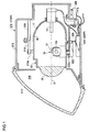
- Fig. 1 is a schematic cross-sectional view illustrating the internal structure of an automotive headlamp 210 used in a light distribution control system according to an embodiment of the present invention.
- the automotive headlamp 210 illustrated in Fig. 1 is a light distribution variable headlamp and is installed singly on each side in the vehicle width direction.
- the structures of the automotive headlamps 210 installed on both sides are substantially the same as each other, and hence the structure of the automotive headlamp 210R, which is installed on the right side, will be described as the representative of both the headlamps.
- the automotive headlamp 210R has a lamp chamber 216, which is formed of both a lamp body 212 with an opening in the vehicle front direction and a transparent cover 214 that covers the opening of the lamp body 212.
- a lamp unit 10 which emits light in the vehicle front direction
- a lamp bracket 218 having a pivot mechanism 218a, which is to be the center of the swing of the lamp unit 10 is formed in part of the lamp unit 10.
- the lamp bracket 218 is connected with a body bracket 220, which is installed upright on the inner wall of the lamp body 212, by fastening members, such as screws. Accordingly, the lamp unit 10 is fixed to a certain position in the lamp chamber 216, and also the posture of the lamp unit 10 can be changed to, for example, forward leaning posture or backward leaning posture, centered on the pivot mechanism 218a.
- the rotation axis 222a of an swivel actuator 222 for structuring an Adaptive Front-lighting System (AFS) for curved roads, which illuminates the traveling direction when driving on a curved road, etc., is fixed to the underside of the lamp unit 10.
- the swivel actuator 222 swivels the lamp unit 10 in the traveling direction, centered on the pivot mechanism 218a, based on the data on the steering amount, which is provided from the vehicle side, on the shape data of the driving road, which is provided from a navigation system, and on the relationship of the relative position between a leading vehicle and the own vehicle, etc.
- the swivel actuator 222 can be structured with, for example, a stepping motor. Alternatively, when the swivel angle is fixed, a solenoid, etc., can be used.
- the swivel actuator 222 is fixed to a unit bracket 224.
- the leveling actuator 226 is structured with, for example, a motor that elongates and contracts a rod 226a in the direction of the arrows M and N.
- the lamp unit 10 swings so as to take backward leaning posture, centered on the pivot mechanism 218a.
- the rod 226a has been contracted in the direction of the arrow N
- the lamp unit 10 swings so as to take forward leaning posture, centered on the pivot mechanism 218a.
- the leveling adjustment for turning the light axis of the lamp unit 10 upwards can be performed.
- the leveling adjustment for turning the light axis thereof downwards can be performed.
- the light axis thereof can be adjusted in accordance with vehicle posture by performing the leveling adjustment as stated above. As a result, the reaching distance of the forward emission by the automotive headlamp 210 can be adjusted to the optimal distance.
- This leveling adjustment can also be performed in accordance with the vehicle posture while driving. For example, a vehicle takes backward leaning posture when accelerated while driving, in contrast, a vehicle takes forward leaning posture when decelerated while driving. Accordingly, the emitting direction of the automotive headlamp 210 also fluctuates up and down, corresponding to a posture state of a vehicle, thereby causing the forward emission distance to be larger or smaller. Accordingly, the reaching distance of the forward emission can be adjusted, even while driving, to the optimal one by performing the leveling adjustment of the lamp unit 10 in real time based on vehicle posture. This is sometimes referred to as "auto leveling".
- an emission controller 228R for controlling the automotive headlamp 210R is arranged.
- the emission controller 228R also performs control of the swivel actuator 222 and the leveling actuator 226, etc.
- the lamp unit 10 can be provided with an aiming adjustment mechanism.
- an aiming pivot mechanism which is to be the center of the swing when the aiming adjustment is performed, is arranged, for example, in the connection portion between the rod 226a of the leveling actuator 226 and the unit bracket 224.
- a pair of aiming adjustment screws which move forward/backward in the vehicle longitudinal direction, are arranged in the connection portion between the body bracket 220 and the lamp bracket 218 so as to create a gap between the aiming adjustment screws in the vehicle width direction. For example, when the two aiming adjustment screws are moved forward, the lamp unit 10 takes forward leaning posture, centered on the aiming pivot mechanism, thereby the light axis being adjusted downward.
- the lamp unit 10 takes backward leaning posture, centered on the aiming pivot mechanism, thereby the light axis being adjusted upward.
- the lamp unit 10 takes clockwise swivel posture, centered on the aiming pivot mechanism, thereby the light axis being adjusted rightward.
- the lamp unit 10 takes counter-clockwise swivel posture, centered on the aiming pivot mechanism, thereby the light axis being adjusted leftward.
- the lamp unit 10 has a shade mechanism 18 including a rotatable shade 12, a bulb 14 as a light source, a lamp housing 17 supporting a reflector 16 on the inner wall, and a projection lens 20.
- the bulb 14 for example, an incandescent bulb, a halogen bulb, an electric discharge bulb, or an LED can be used. In the present embodiment, an example is described in which the bulb 14 is structured with a halogen bulb.
- the reflector 16 reflects the light emitted from the bulb 14. Part of both the light emitted from the bulb 14 and the light reflected by the reflector 16 are guided to the projection lens 20 through the rotatable shade 12 of which the shade mechanism 18 is composed.
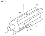
- Fig. 2 is a schematic perspective view of the rotatable shade 12.
- the rotatable shade 12 is a cylindrically-shaped member that is rotatable around the rotation axis 12a.
- the rotatable shade 12 has a notch 22 in which part of the rotatable shade 12 is cut off in the axial direction, and holds a plurality of plate-shaped shade plates 24 on the outer circumferential surface 12b other than the notch 22.
- the rotatable shade 12 can transfer the notch 22 or any one of the plurality of shade plates 24 into a position on the back focal plane including the back focus of the projection lens 20 in accordance with its rotation angle.
- the light distribution pattern following the shape of the ridge of the shade plate 24, which is located on the light axis O in accordance with the rotation angle of the rotatable shade 12, is formed. For example, by transferring any one of the plurality of shade plates 24 onto the light axis O so as to shade part of the light emitted from bulb 14, a light distribution pattern for low beam or a light distribution pattern, in part of which a characteristic of a light distribution pattern for low beam is included, is formed. Further, by transferring the notch 22 onto the light axis O so as not to shade the light emitted from the bulb 14, a light distribution pattern for high beam is formed.
- the rotatable shade 12 can be rotated with a shade motor (not illustrated) and can transfer the shade plate 24 for forming a rotationally desired light distribution pattern or the notch 22 onto the light axis O by controlling a rotation amount of the shade motor.
- the rotatable shade 12 may be designed to have only a shading function with the notch 22 of the outer circumferential surface 12b of the rotatable shade 12 being omitted.
- the rotatable shade 12 is designed to retract from the position on the light axis O by driving, for example, a solenoid, etc.
- the projection lens 20 is arranged on the light axis O that extends in the vehicle longitudinal direction and the bulb 14 is arranged on the back side of the back focal surface of the projection lens 20.
- the projection lens 20 is composed of a plano-convex aspheric lens, the front surface of which is convex-shaped and the back surface of which is flat-shaped, and the projection lens 20 projects, as an inverted image, the image of the light source that is formed on the back focal surface onto the virtual vertical screen in front of the automotive headlamp 210.
- Figs. 3A to 3F are views illustrating the light distribution patterns that can be emitted by the automotive headlamp 210 according to the present embodiment.
- Figs. 3A to 3F illustrate the light distribution patterns that are formed on the virtual vertical screen, which is arranged at a position 25 m distant from the front of the automotive headlamp 210.
- six light distribution patterns illustrated in Figs. 3A to 3F can be formed.
- Each of the light distribution patterns illustrated in Figs. 3A to 3F is a synthesized light distribution pattern that is formed by superimposing one of the light distribution patterns, which are respectively formed by the automotive headlamps 210 arranged on both sides in the vehicle width direction, on the other.
- Fig. 3A illustrates a light distribution pattern for low beam.
- the light distribution pattern for low beam is a light distribution pattern, taking into consideration not to provide glare to an oncoming vehicle or a pedestrian in urban area driving in an area of left-hand traffic prescribed by traffic regulations.
- Fig. 3B illustrates a light distribution pattern for high beam.
- the light distribution pattern for high beam is a light distribution pattern in which forward visibility of a driver can be secured to the maximum.
- Fig. 3C illustrates a light distribution pattern for left-sided high beam, which is used in an area of left-hand traffic prescribed by traffic regulations.
- the light distribution pattern for left-sided high beam is formed by being synthesized from a light distribution pattern for left-sided high beam, which is formed by the automotive headlamp 210 on the left side, and a light distribution pattern for low beam, which is formed by the automotive headlamp 210 on the right side.
- Such a light distribution pattern for left-sided high beam is suitable when nor a leading vehicle nor a pedestrian is present on the own lane side but an oncoming vehicle or a pedestrian is present on the opposite lane side.
- the light distribution pattern is a light distribution pattern, taking into consideration not to provide glare to an oncoming vehicle or a pedestrian on the opposite lane while enhancing forward visibility of a driver.
- Fig. 3D illustrates a light distribution pattern for right-sided high beam, which is used in an area of left-hand traffic prescribed by traffic regulations.
- the light distribution pattern for right-sided high beam is formed by being synthesized from a light distribution pattern for right-sided high beam, which is formed by the automotive headlamp 210 on the right side, and a light distribution pattern for low beam, which is formed by the automotive headlamp 210 on the left side.
- Such a light distribution pattern for right-sided high beam is suitable when a leading vehicle or a pedestrian is present on the own lane side, but neither an oncoming vehicle nor a pedestrian is present on the opposite lane side.
- the light distribution pattern is a light distribution pattern, taking into consideration not to provide glare to a leading vehicle or a pedestrian on the own lane while enhancing forward visibility of a driver.
- Fig. 3E is a variation of a light distribution pattern for low beam, in which emission of light toward the periphery of the cross point between the vertical line V and the horizontal line H on the virtual vertical screen is suppressed.
- the light distribution pattern illustrated in Fig. 3E is one referred to as a "V light distribution pattern".
- This V light distribution pattern forms, for example, a light distribution pattern for low beam, which is illustrated in Fig. 3A , by the automotive headlamp 210 on the left side.
- the V light distribution pattern forms, by the automotive headlamp 210 on the right side, a light distribution pattern for low beam, which is used in an area of right-hand traffic prescribed by traffic regulations, namely, a light distribution pattern that has line symmetry of a light distribution pattern illustrated in Fig. 3A with respect to the vertical line V.
- a V light distribution pattern can be formed, in which emission of light toward the periphery of the remote cross point between the vertical line V and the horizontal line H where a preceding vehicle or an oncoming vehicle may be possibly present is suppressed.
- the V light distribution pattern can be said to be a light distribution pattern that facilitates a driver to recognize an obstacle, etc., located in road shoulder on the own lane side or the opposite lane side while suppressing glare to a remote leading vehicle.
- Fig. 3F is a variation of a light distribution pattern for left-sided high beam, which is illustrated in Fig. 3C , and of a light distribution pattern for right-sided high beam, which is illustrated in Fig. 3D , and is one referred to as a "split light distribution pattern".
- This split light distribution pattern is a light distribution pattern in which the visibility to the outside of the own lane and the opposite lane can be sufficiently secured while suppressing emission of light into the own lane and the opposite lane.
- Such a split light distribution pattern is formed, for example, as follows.
- a light distribution pattern for left-sided high beam which is illustrated in Fig.
- a light distribution pattern for right-sided high beam which is illustrated in Fig. 3D , is formed in a state where the automotive headlamp 210 on the right side is swiveled rightward at a predetermined angle.
- a split light distribution pattern as illustrated in Fig. 3F can be formed by superimposing the light distribution pattern for left-sided high beam onto the light distribution pattern for right-sided high beam.
- six types of light distribution patterns consisting of a light distribution pattern for low beam, a light distribution pattern for high beam, a light distribution pattern for left-sided high beam, a light distribution pattern for right-sided high beam, a V light distribution pattern, and a split light distribution pattern, can be formed.
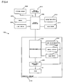
- Fig. 4 is a functional block diagram for explaining a light distribution control system 100 according to an embodiment of the present invention.
- the light distribution control system 100 comprises the aforementioned automotive headlamp 210, a vehicle controller 302 configured to control the automotive headlamp 210, a light switch 304, a camera 306, a steering sensor 308, a vehicle speed sensor 310, and a navigation system 312.
- the emission controller 228 of the automotive headlamp 210 controls a power supply circuit 230 in accordance with a command by the vehicle controller 302, which is installed in a vehicle, so that control of turning on the bulb 14 is performed.
- the emission controller 228 controls the leveling actuator 226, the swivel actuator 222, and the shade motor 221 in accordance with a command from the vehicle controller 302.
- the emission controller 228 controls the swivel actuator 222 while swiveling, such as driving on a curved road and driving left or right, so that the light axis of the lamp unit 10 is directed to the direction in which the vehicle will travel.
- the emission controller 228 controls the leveling actuator 226 in accordance with backward leaning or forward leaning of a vehicle posture when the vehicle is accelerated or decelerated, so that the reaching distance of the forward emission is adjusted to the optimal distance by adjusting the light axis of the lamp unit 10 in the vehicle vertical direction.
- the emission controller 228 controls the leveling actuator 226, the swivel actuator 222, and the shade motor 221 in accordance with a command regarding a light distribution pattern from the vehicle controller 302.
- a light distribution pattern can be manually switched to another in accordance with an operation of the light switch 304 by a driver.
- a mode in which a light distribution pattern is manually controlled as stated above is appropriately referred to as a "manual mode".
- the vehicle controller 302 issues a command to the emission controller 228 so as to form a light distribution pattern for low beam.
- the emission controller 228 controls the leveling actuator 226, the swivel actuator 222, and shade motor 221 such that a light distribution pattern for low beam is formed.
- a light distribution pattern which is optimal for the situations around a vehicle, can be formed by detecting the situations therearound with various sensors, not by an operation of the light switch 304.
- ADB Adaptive Driving Beam
- the vehicle controller 302 determines that glare to the leading vehicle should be prevented and issues a command to the emission controller 228 such that, for example, a light distribution pattern for low beam is formed.
- the vehicle controller 302 determines that the visibility of the driver should be enhanced and issues a command to the emission controller 228 such that, for example, a light distribution pattern for high beam is formed.
- a camera 306 such as a stereo camera, is connected with the vehicle controller 302 as a means for recognizing a target.
- the image data imaged with the camera 306 is transmitted to the vehicle controller 302 and then the vehicle controller 302 performs image analysis through signal processing of the image data such that a leading vehicle within the imaging range is detected.
- the vehicle controller 302 selects the optimal light distribution pattern based on the acquired information on the leading vehicle and issues a command to the emission controller 228 so as to form the selected light distribution pattern.
- the means for detecting a leading vehicle can be appropriately modified and another detection means, such as a millimeter-wave radar and an infrared radar, may be used instead of the camera 306. Alternatively, a combination of them may be used.
- the vehicle controller 302 can also acquire information from the steering sensor 308 and the vehicle speed sensor 310, etc., which are usually installed in a vehicle, and hence can select a light distribution pattern to be formed in accordance with a driving state or driving posture of a vehicle, or can change a light distribution pattern in a simplified manner by changing the direction of the light axis. For example, when determining that a vehicle is swiveling based on the information from the steering sensor 308, the vehicle controller 302 performs rotation control on the rotatable shade 12 such that a light distribution pattern for enhancing the visibility in the swivel direction is formed. Alternatively, the visibility may be enhanced by directing the light axis of the lamp unit 10 to the swivel direction with the swivel actuator 222 being controlled, without changing the rotation state of the shade 12.
- the vehicle controller 302 can also acquire information on the shape or form of a road, and that on the installation of a road sign, etc., from the navigation system 312. By acquiring these information beforehand, a light distribution pattern, which is suitable for a driving road, can also be smoothly formed with the leveling actuator 226, the swivel actuator 222, and the shade motor 221, etc., being controlled.
- the detection accuracy of a leading vehicle is important, the detection being performed based on the image data from the camera 306. If the detection accuracy is low, there is the fear that glare may be provided to a leading vehicle due to a failure in detecting the leading vehicle, or that a driver may feel a sense of discomfort because light distribution patterns are frequently switched due to repeated false detection.
- an ultra-sensitive camera by which a clear image can be obtained even at night is used; however, use of such an ultra-sensitive camera makes the cost high. Therefore, in the present embodiment, a technique will be proposed in which glare to a leading vehicle can be prevented even when an inexpensive camera, the sensitivity of which is not so high, is used.
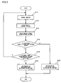
- Fig. 5 is a flow chart for explaining switching control of light distribution patterns in the light distribution control system 100 according to the present embodiment.
- the control described hereinafter is switching control of light distribution patterns in the ADB mode.
- the switching control of light distribution patterns in accordance with the flow chart illustrated in Fig. 5 is repeatedly performed at every predetermined time.
- the front of a vehicle is at first imaged with the camera 306 (S10).
- the camera 306 is configured to image at a predetermined imaging cycle Tp (second).
- the imaged data is transmitted to the vehicle controller 302.
- the vehicle controller 302 performs image analysis on the image data, which have been provided from the camera 306, so that a leading vehicle within the imaging range is detected (S12).
- the vehicle controller 302 selects the optimal light distribution pattern from the six types of the light distribution patterns, which are illustrated in Figs. 3A to 3F , based on the acquired information on the leading vehicle (S14). For example, when vehicles are present in the opposite lane and the own lane, a light distribution pattern for low beam, which is illustrated in Fig. 3A , is selected.
- a light distribution pattern for high beam which is illustrated in Fig. 3B
- a light distribution pattern for left-sided high beam which is illustrated in Fig. 3C
- the vehicle controller 302 outputs the information on the selected light distribution pattern to the emission controller 228 in the automotive headlamp 210.
- the emission controller 228 determines whether the emission range of the light distribution pattern selected by the vehicle controller 302 is wider than that of the light distribution pattern, which is currently being emitted (S16). For example, when the light distribution, which is currently being emitted, is a light distribution pattern for low beam and the selected light distribution pattern is that for high beam, the emission controller 228 determines that the emission range is wider.
- the emission controller 228 determines whether the light distribution pattern, which has been selected this time, is selected a predetermined specified number of times (N times) in a row (S18).
- the emission controller 228 is provided with a counter for counting the number of times in which the same light distribution pattern is continued. This counter is reset when the same light distribution pattern is discontinued.
- the specified number of times is set to a value greater than or equal to 2.
- the emission controller 228 controls the leveling actuator 226, the swivel actuator 222, and the shade motor 221, etc., so that the present light distribution pattern is switched to the selected light distribution pattern (S20).
- the control flow returns to S10 such that imaging with the camera 306 is performed after elapse of the imaging cycle Tp.
- the control flow is transferred to S20 such that the light distribution pattern is switched.
- the emission controller 228 controls the leveling actuator 226, the swivel actuator 222, and the shade motor 221 such that the selected light distribution pattern is immediately emitted (S22).
- the selected light distribution pattern is the same as the present light distribution pattern, the present control is maintained.
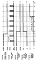
- Figs. 6A to 6E are timing charts for explaining the control performed when switching to a light distribution pattern with a wider emission range.
- Fig. 6A illustrates an actual state of a leading vehicle
- Fig. 6B illustrates the imaging timing of the camera 306
- Fig. 6C illustrates a detection result of the leading vehicle by the vehicle controller 302
- Fig. 6D illustrates selection of a light distribution pattern by the vehicle controller 302
- Fig. 6E illustrates control of the automotive headlamp 210 by the emission controller 228.
- description will be made, assuming a situation in which a light distribution pattern for low beam is at first emitted because a leading vehicle is present, and then a light distribution pattern for high beam will be switched to because no leading vehicle is present on the way. Further, the description will be made, assuming that the specified number of times N is 4.
- the camera 306 images the front of a vehicle at every predetermined imaging cycle Tp second.
- the vehicle controller 302 detects a leading vehicle at each imaging time based on the image data from the camera 306, thereby selecting the optimal light distribution pattern.
- a leading vehicle is present in front of the own vehicle at the time t1 and t2. Accordingly, the vehicle controller 302 detects that a leading vehicle is present at the time t1 and t2, therefore selecting a light distribution pattern for low beam. At the time t1 and t2, because the same light distribution pattern as the light distribution pattern that is being emitted at the time is selected, a light distribution pattern for low beam is maintained as it is.
- the vehicle controller 302 detects that no leading vehicle is present at the time t3, based on the imaged data that has been imaged at the time t3, immediately after the time t2' , as illustrated in Fig. 6C . Because no leading vehicle is present, the vehicle controller 302 selects a light distribution pattern for high beam at the time t3, as illustrated in Fig. 6D . The information on the selected light distribution pattern is transmitted to the emission controller 228.
- the emission controller 228 determines whether the emission range of the selected light distribution pattern is wider than that of the light distribution pattern, which is currently being emitted. Because the actual emission pattern at the time t3 is a light distribution pattern for low beam and because the vehicle controller 302 selects a light distribution pattern for high beam, it is switching to a light distribution pattern with a wider emission range. However, because a light distribution pattern for high beam has been selected only once at the time t3, switching of a light distribution pattern is not immediately performed in accordance with S18 in the flow chart illustrated in Fig.
- the specified number of times N is set to 4, switching from a light distribution pattern for low beam to that for high beam is performed at the time t6 when a light distribution pattern for high beam has been selected four times in a row. That is, when no leading vehicle is detected by the vehicle controller 302 four times in a row, the emission controller 228 determines that no leading vehicle is present, thereby performing switching of a light distribution pattern.
- (Tp x 3) seconds are needed since the time t3 when it is detected for the first time by the vehicle controller 302 that no leading vehicle is present until a light distribution pattern is switched to by the emission controller 228 after it is determined that no leading vehicle is present.
- a light distribution pattern for low beam is selected after detecting, even once during (Tp x 3) seconds, that a leading vehicle is present, the counter for counting the number of times in which the same light distribution pattern is continued is reset, and hence switching of a light distribution pattern is not performed at the time t6.
- the time elapsed since there occurs a change in a detection result of a leading vehicle by the vehicle controller 302 until switching of a light distribution pattern is started after determining the change is referred to as the "detection time ⁇ T".
- switching to a new light distribution pattern is not immediately performed by the emission controller 228 even when there occurs a change in a detection result of a leading vehicle, and it is designed that switching to a new light distribution pattern is performed after elapse of the detection time ⁇ T.
- switching to a light distribution pattern with a wider emission range such as the case where a light distribution pattern for low beam is switched to that for high beam, there is the fear that glare may be provided to a leading vehicle if the detection of a leading vehicle by the vehicle controller 302 is failed.
- the detection of a leading vehicle is repeatedly performed during the detection time ⁇ T, in preference of the detection accuracy of a leading vehicle to the switching speed of a light distribution pattern. Because the detection accuracy can be enhanced by detecting a leading vehicle for long time in comparison with the case where presence/absence of a leading vehicle is determined by only one time of detection, it can be suppressed that glare may be provided to a leading vehicle.
- Figs. 7A to 7E are timing charts for explaining the control performed when switching to a light distribution pattern with a narrower emission range.
- Fig. 7A illustrates an actual state of a leading vehicle
- Fig. 7B illustrates the imaging timing of the camera 306
- Fig. 7C illustrates a detection result of the leading vehicle by the vehicle controller 302
- Fig. 7D illustrates selection of a light distribution pattern by the vehicle controller 302
- Fig. 7E illustrates control of the automotive headlamp 210 by the emission controller 228.
- description will be made, assuming a situation in which a light distribution pattern for high beam is at first emitted because no leading vehicle is present, and then a light distribution pattern for low beam will be switched to because a leading vehicle is present on the way.
- the vehicle controller 302 detects that no leading vehicle is present at the time t1 and t2, therefore selecting a light distribution pattern for high beam.
- a light distribution pattern for high beam is maintained as it is.
- a leading vehicle is present at the time t2' between the time t2 and t3, as illustrated in Fig. 7A .
- the vehicle controller 302 detects that a leading vehicle is present at the time t3, based on the imaged data that has been imaged at the time t3, immediately after the time t2' , as illustrated in Fig. 7C . Because a leading vehicle is present, the vehicle controller 302 selects a light distribution pattern for low beam at the time t3, as illustrated in Fig. 7D . The information on the selected light distribution pattern is transmitted to the emission controller 228.
- the emission controller 228 determines whether the emission range of the selected light distribution pattern is wider than that of the light distribution pattern, which is currently being emitted. Because the actual emission pattern at the time t3 is a light distribution pattern for high beam and because the vehicle controller 302 selects a light distribution pattern for low beam, it is switching to a light distribution pattern with a narrower emission range. Accordingly, switching of a light distribution pattern is immediately performed at the time t3, as illustrated in the flow chart in Fig. 5 .
- the light distribution control system 100 when switching to a light distribution pattern with a narrower emission range is performed, it is designed that switching to a new light distribution pattern is performed immediately after it is detected that there occurs a change in a detection result of a leading vehicle by the emission controller 228. That is, the switching of a light distribution pattern is performed on condition that the detection time ⁇ T is 0 second.
- the switching of a light distribution pattern is performed on condition that the detection time ⁇ T is 0 second.
- switching of a light distribution pattern is performed on condition that the detection time ⁇ T is 0 second, in preference of rapid switching to the optimal light distribution pattern to the detection accuracy of a leading vehicle.
- the detection time ⁇ T is 0 second when switching to a light distribution pattern with a narrower emission range is performed; however, the detection time ⁇ T shall not be limited to 0 second.
- the detection time ⁇ T may be set to Tp such that switching of a light distribution pattern is rapidly performed while enhancing the detection accuracy of a leading vehicle.
- Fig. 8 is a view illustrating detection time between each light distribution pattern when an emission range is widened.
- the detection time when a light distribution pattern for low beam is switched to that for high beam, to a V light distribution pattern, to that for right-sided high beam, to a split light distribution pattern, and to that for left-sided high beam are represented by ⁇ T1, ⁇ T2, ⁇ T3, ⁇ T4, and ⁇ T5, respectively.
- the detection time when a V light distribution pattern is switched to a light distribution pattern for high beam, to a split light distribution pattern, to a light distribution pattern for right-sided high beam, and to that for left-sided high beam are represented by ⁇ T6, ⁇ T13, ⁇ T14, ⁇ T15, respectively.
- the detection time when a light distribution pattern for right-sided high beam is switched to that for high beam, and to a split light distribution pattern are represented by ⁇ T7 and ⁇ T8, respectively.
- the detection time when a light distribution pattern for left-sided high beam is switched to that for high beam, and to a split light distribution pattern are represented by ⁇ T9 and ⁇ T10, respectively.
- the detection time when a split light distribution pattern is switched to a light distribution pattern for high beam is represented by ⁇ T11. Further, the detection when switching between a light distribution pattern for left-sided high beam and that for right-sided high beam is performed is represented by ⁇ T12. It is noted that, in the switching between a light distribution pattern for left-sided high beam and that for right-sided high beam, both areas of the emission ranges are almost the same as each other.
- the detection time ⁇ T1 to ⁇ T11 and ⁇ T13 to ⁇ T15 are set to, for example, approximately 1 to 2 seconds.
- the detection time ⁇ T1 to ⁇ T11 and ⁇ T13 to ⁇ T15 may be the same or different.
- the optimal detection time may be appropriately determined by experiment or simulation.
- the detection time ⁇ T12 when the switching between a light distribution pattern for right-sided high beam and that for left-sided high beam is performed, is set to the time smaller than or equal to the detection time ⁇ T1 to ⁇ T11 and ⁇ T13 to ⁇ T15, for example, to 0 to 0. 5 seconds, in order to prevent glare.
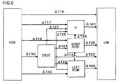
- Fig. 9 is a view illustrating the detection time between each light distribution pattern when an emission range is narrowed.
- the detection time when a light distribution pattern for high beam is switched to that for low beam, to a V light distribution pattern, to that for right-sided high beam, to a split light distribution pattern, and to that for left-sided high beam are represented by ⁇ T16, ⁇ T17, ⁇ T18, ⁇ T19, and ⁇ T20, respectively.
- the detection time when a split light distribution pattern is switched to that for right-sided high beam, to that for left-sided high beam, to that for low beam, and to a V light distribution pattern are represented by ⁇ T21, ⁇ T22, ⁇ T23, and ⁇ T27, respectively.
- the detection time when a V light distribution pattern is switched to a light distribution pattern for low beam is represented by ⁇ T24.
- the detection time when a light distribution pattern for right-sided high beam is switched to that for low beam, and to a V light distribution pattern are represented by ⁇ T25 and ⁇ T28, respectively.
- the detection time when a light distribution pattern for left-sided high beam is switched to that for low beam, and to a V light distribution pattern are represented by ⁇ T26 and ⁇ T29, respectively.
- the detection time ⁇ T16 to ⁇ T29 are set to a time smaller than the detection time ⁇ T1 to ⁇ T11 and ⁇ T13 to ⁇ T15, which are illustrated in Fig. 8 .
- the detection time ⁇ T16 to ⁇ T29 are set to 0 to approximately 0.5 seconds.
- the detection time ⁇ T16 to ⁇ T29 may be the same or different.
- the detection time ⁇ T of a leading vehicle when switching to a light distribution pattern with a wider emission range, is set to be larger than that set when switching to a light distribution pattern with a narrower emission range.
- the detection accuracy of a leading vehicle can be enhanced when switching to a light distribution pattern with a wider emission range, and hence it can be suppressed that glare may be provided to a leading vehicle.
- the optimal light distribution pattern when switching to a light distribution pattern with a narrower emission range, the optimal light distribution pattern can be rapidly switched to by setting the detection time ⁇ T of a leading vehicle to be small.
- the detection accuracy of a leading vehicle can be enhanced without an expensive, ultra-sensitive camera, and hence a light distribution control system can be attained with an inexpensive structure, in which it can be prevented that glare may be provided to a leading vehicle.
- the detection accuracy of a leading vehicle varies in accordance with various driving states of a vehicle. Accordingly, the vehicle controller 302 and the emission controller 228 may change the detection time ⁇ T in accordance with a driving state of a vehicle.
- a rain sensor 311 for detecting rain may be connected with the vehicle controller 302 such that, when it is raining, the detection time ⁇ T is set to be larger than that set when there is any weather other than rain. For example, when switching a light distribution pattern for low beam to that for high beam and when the detection time is set to 1 second when there is any weather other than rain, the detection time is changed to 3 seconds when it is raining. Thereby, the detection accuracy of a leading vehicle can be enhanced when it is raining.
- the vehicle controller 302 and the emission controller 228 may determine whether a vehicle is driving on a curved road based on the information from the steering sensor 308, the vehicle speed sensor 310, and the navigation system 312, etc., so that, when driving on a curved road, the detection time ⁇ T is set to be larger than that set when driving on any road other than a curved road. For example, when switching a light distribution pattern for low beam to that for high beam and when the detection time ⁇ T on a straight road is set to 1 second, the detection time ⁇ T on a curved rod is changed to 5 seconds. Thereby, it can be prevented that light distribution patterns are frequently switched on a curved road, thereby suppressing a driver from feeling a sense of discomfort.
- the detection time ⁇ T of a leading vehicle when switching to a light distribution pattern with a wider emission range than before, the detection time ⁇ T of a leading vehicle is set to be larger than that set when switching to a light distribution pattern with a narrower emission range.
- the fear that glare may be provided to a leading vehicle can be reduced because of the enhanced detection accuracy of a leading vehicle with such a structure, it takes a long time until, for example, a light distribution pattern for high beam is switched to after no leading vehicle was present in front of a vehicle.
- the vehicle controller 302 and the emission controller 228 may change the detection time ⁇ T in accordance with the horizontal position of a leading vehicle.
- Fig. 10 is a view for explaining variable control of the detection time ⁇ T in accordance with the horizontal position of a leading vehicle.
- Fig. 10 illustrates the control when driving on a straight road.
- the vertical axis represents the detection time ⁇ T
- the horizontal axis represents the horizontal position of a leading vehicle when perspectively viewing the front of the own vehicle from the own vehicle (angle ⁇ formed between the straight line, extending from the own vehicle toward the front of the own vehicle, and the straight line connecting the own vehicle with the leading vehicle).
- the cross point between the vertical axis and the horizontal axis represents the front of the own vehicle.
- the detection time ⁇ T is set to be large when a leading vehicle is present in an area in front of the own vehicle, and is set to be smaller as the position of the leading vehicle deflects leftward or rightward from the front of the own vehicle, as illustrated in Fig. 10 .
- the detection time ⁇ T is set to be large in order to more carefully perform detection of a leading vehicle, which is present in front of the own vehicle.
- the detection time ⁇ T is set to be smaller as the position of the leading vehicle deflects leftward or rightward from the front of the own vehicle, in preference of enhanced visibility due to rapid switching of a light distribution pattern to the detection accuracy.
- Fig. 10 illustrates the control when driving on a straight road.
- the detection time ⁇ T may be set to be large when a leading vehicle is present around the swivel angle and may be set to be smaller as the position of the leading vehicle deflects from the swivel angle.
- the vehicle controller 302 and the emission controller 228 may detect the distance to a leading vehicle based on the information from the camera 306 or an inter-vehicular distance sensor such that, when the distance to the leading vehicle is larger than a predetermined threshold distance, the detection time ⁇ T of the leading vehicle is set to be larger than that set when the distance to the leading vehicle is smaller than or equal to the predetermined threshold distance.
- the detection accuracy of a leading vehicle varies in accordance with the distance between the own vehicle and a leading vehicle. That is, the detection accuracy is deteriorated as a leading vehicle is remote from the own vehicle.
- switching of a light distribution pattern can be rapidly performed for a change in presence/absence of a leading vehicle near the own vehicle while enhancing the detection accuracy of a leading vehicle, which is remote from the own vehicle, by setting, when a leading vehicle is more remote than a predetermined threshold distance, the detection time ⁇ T to be larger than that set when a leading vehicle is closer than the predetermined threshold distance.
- manual switching of a light distribution pattern can be performed by a driver operating the light switch 304, other than the ADB mode in which the optimal light distribution pattern is formed in accordance with situations surrounding a vehicle.
- the vehicle controller 302 and the emission controller 228 control the leveling actuator 226, the swivel actuator 222, and the shade motor 221 such that the light distribution pattern is gradually switched to.
- rapid switching of a light distribution pattern is avoided, and hence it can be suppressed that a driver may feel a sense of discomfort, which accompanies a change in light distribution pattern.
- Figs. 11A to 11F are views for explaining control of a light distribution pattern for enhancing visibility on a curved road.
- Figs. 11A to 11C are views illustrating a change in light distribution pattern when the control is performed in accordance with the control flow illustrated in Fig. 5 .
- description will be made, assuming that an oncoming vehicle C is approaching from a remote position while driving on a curved road that curves left.
- the vehicle controller 302 and the emission controller 228 select and emit a light distribution pattern for right--sided high beam R-Hi. Subsequently, when the oncoming vehicle C approaches the vicinity of the front of the own vehicle, as illustrated in Fig. 11B , the vehicle controller 302 and the emission controller 228 select and emit a light distribution pattern for low beam Lo.
- the oncoming vehicle C when the oncoming vehicle C almost passes the own vehicle after further approaching the own vehicle, the oncoming vehicle C is present on the right side of the front of the own vehicle, when viewed from the own vehicle, as illustrated in Fig. 11C .
- a light distribution pattern for high beam is emitted.
- switching of a light distribution pattern for low beam to that for high beam is the switching to a light distribution pattern with a wider emission range, and hence the detection time ⁇ T is set to be large and the switching is delayed. As a result, there is the fear that the visibility of remote areas on a curved road may be impaired.
- Figs. 11D to 11F are views illustrating the improved switching control of a light distribution pattern on a curved road.
- the control illustrated in Figs. 11D and 11E are the same as that illustrated in Figs. 11A and 11B .
- the detection time ⁇ T is set to be smaller than usual when switching a light distribution pattern for low beam to the other of the aforementioned two light distribution patterns.
Description
- The present invention relates to a light distribution control system for an automotive headlamp.
- Conventionally, the automotive headlamps have been presented in which presence or absence of a preceding vehicle or an oncoming vehicle (hereinafter, appropriately referred to as a "leading vehicle") is detected based on an image of the front of a vehicle, which has been imaged with a camera, and then a light distribution pattern is changed based on a detection result (see, for example,
Patent Documents 1 and 2 andUS 2005/0242740 A1 ). - [Patent Document 1] Japanese Patent Application Publications No.
2008-94127 - [Patent Document 2] Japanese Patent Application Publications No.
2008-37240 - In the aforementioned automotive headlamp, the detection accuracy of a leading vehicle is important, the detection being performed based on the image data from a camera. If the detection accuracy is low, there is the fear that glare may be provided to a leading vehicle due to a failure in detecting the leading vehicle. In order to enhance the detection accuracy of a leading vehicle, it can be considered that an ultra-sensitive camera by which a clear image can be obtained even at night is used; however, use of such an ultra-sensitive camera makes the cost very high.
- The present invention has been made in view of these situations and provides a light distribution control system for an automotive headlamp in which glare is hardly provided to a leading vehicle with an inexpensive structure.
- In order to solve the aforementioned challenge, a light distribution control system for an automotive headlamp according to
claim 1 is proposed. - Some optional features of the invention are recited in the dependent claims.
- Embodiments will now be described by way of example only, with reference to the accompanying drawings ,in which:
-
Fig. 1 is a schematic cross-sectional view illustrating the internal structure of an automotive headlamp; -
Fig. 2 is a schematic perspective view of a rotatable shade; -
Figs. 3A to 3F are views illustrating light distribution patterns that can be emitted by the automotive headlamp; -
Fig. 4 is a functional block diagram for explaining the light distribution control system of an embodiment; -
Fig. 5 is a flow chart for explaining switching control of a light distribution pattern in the light distribution control system of the present embodiment; -
Figs. 6A to 6E are timing charts for explaining the control when switching to a light distribution pattern with a wider emission range; -
Figs. 7A to 7E are timing charts for explaining the control when switching to a light distribution pattern with a narrower emission range; -
Fig. 8 is a view illustrating detection time between each light distribution pattern when an emission range is widened; -
Fig. 9 is a view illustrating the detection time between each light distribution pattern when an emission range is narrowed; -
Fig. 10 is a view for explaining variable control of the detection time in accordance with the horizontal position of a leading vehicle; and -
Figs. 11A to 11F are views for explaining control of a light distribution pattern for enhancing visibility on a curved road. - A light distribution control system for an automotive headlamp of an embodiment can detect a leading vehicle, which is present in front of the own vehicle, and selects the optimal light distribution pattern from a plurality of light distribution patterns based on a result of the detection, so that the optimal light distribution pattern is emitted. In this light distribution control system, the time for detecting a leading vehicle is set to be longer when switching to a light distribution pattern with a wider emission range than before, than that set when switching to a light distribution pattern with a narrower emission range. For example, when switching from a light distribution pattern for low beam to that for high beam, the time for detecting a leading vehicle is set to be larger than vice versa. Thereby, the detection accuracy of a leading vehicle can be enhanced when switching to a light distribution pattern with a wider emission range and it can be prevented that glare may be provided to the leading vehicle.
- Hereinafter, an embodiment of the present invention will be described in detail with reference to the accompanying drawings.
-
Fig. 1 is a schematic cross-sectional view illustrating the internal structure of anautomotive headlamp 210 used in a light distribution control system according to an embodiment of the present invention. Theautomotive headlamp 210 illustrated inFig. 1 is a light distribution variable headlamp and is installed singly on each side in the vehicle width direction. The structures of theautomotive headlamps 210 installed on both sides are substantially the same as each other, and hence the structure of theautomotive headlamp 210R, which is installed on the right side, will be described as the representative of both the headlamps. - The
automotive headlamp 210R has alamp chamber 216, which is formed of both alamp body 212 with an opening in the vehicle front direction and atransparent cover 214 that covers the opening of thelamp body 212. In thelamp chamber 216, alamp unit 10, which emits light in the vehicle front direction, is housed. Alamp bracket 218 having apivot mechanism 218a, which is to be the center of the swing of thelamp unit 10, is formed in part of thelamp unit 10. Thelamp bracket 218 is connected with abody bracket 220, which is installed upright on the inner wall of thelamp body 212, by fastening members, such as screws. Accordingly, thelamp unit 10 is fixed to a certain position in thelamp chamber 216, and also the posture of thelamp unit 10 can be changed to, for example, forward leaning posture or backward leaning posture, centered on thepivot mechanism 218a. - The
rotation axis 222a of answivel actuator 222 for structuring an Adaptive Front-lighting System (AFS) for curved roads, which illuminates the traveling direction when driving on a curved road, etc., is fixed to the underside of thelamp unit 10. Theswivel actuator 222 swivels thelamp unit 10 in the traveling direction, centered on thepivot mechanism 218a, based on the data on the steering amount, which is provided from the vehicle side, on the shape data of the driving road, which is provided from a navigation system, and on the relationship of the relative position between a leading vehicle and the own vehicle, etc. As a result, the emission range of thelamp unit 10 is directed to the front of a curve of a curved road, not to the front of the own vehicle, thereby enhancing the forward visibility of a driver. Theswivel actuator 222 can be structured with, for example, a stepping motor. Alternatively, when the swivel angle is fixed, a solenoid, etc., can be used. - The
swivel actuator 222 is fixed to aunit bracket 224. A levelingactuator 226, which is arranged outside thelamp body 212, is connected with theunit bracket 224. The levelingactuator 226 is structured with, for example, a motor that elongates and contracts arod 226a in the direction of the arrows M and N. When therod 226a has been elongated in the direction of the arrow M, thelamp unit 10 swings so as to take backward leaning posture, centered on thepivot mechanism 218a. In contrast, when therod 226a has been contracted in the direction of the arrow N, thelamp unit 10 swings so as to take forward leaning posture, centered on thepivot mechanism 218a. When thelamp unit 10 takes backward leaning posture, the leveling adjustment for turning the light axis of thelamp unit 10 upwards can be performed. In contrast, when thelamp unit 10 takes forward leaning posture, the leveling adjustment for turning the light axis thereof downwards can be performed. The light axis thereof can be adjusted in accordance with vehicle posture by performing the leveling adjustment as stated above. As a result, the reaching distance of the forward emission by theautomotive headlamp 210 can be adjusted to the optimal distance. - This leveling adjustment can also be performed in accordance with the vehicle posture while driving. For example, a vehicle takes backward leaning posture when accelerated while driving, in contrast, a vehicle takes forward leaning posture when decelerated while driving. Accordingly, the emitting direction of the
automotive headlamp 210 also fluctuates up and down, corresponding to a posture state of a vehicle, thereby causing the forward emission distance to be larger or smaller. Accordingly, the reaching distance of the forward emission can be adjusted, even while driving, to the optimal one by performing the leveling adjustment of thelamp unit 10 in real time based on vehicle posture. This is sometimes referred to as "auto leveling". - An
emission controller 228, which performs control of turning on/off thelamp unit 10 and control of forming a light distribution pattern, is arranged on the inner wall of thelamp chamber 216, for example, at a lower position of thelamp unit 10. InFig. 1 , an emission controller 228R for controlling theautomotive headlamp 210R is arranged. The emission controller 228R also performs control of theswivel actuator 222 and theleveling actuator 226, etc. - The
lamp unit 10 can be provided with an aiming adjustment mechanism. For example, an aiming pivot mechanism, which is to be the center of the swing when the aiming adjustment is performed, is arranged, for example, in the connection portion between therod 226a of the levelingactuator 226 and theunit bracket 224. A pair of aiming adjustment screws, which move forward/backward in the vehicle longitudinal direction, are arranged in the connection portion between thebody bracket 220 and thelamp bracket 218 so as to create a gap between the aiming adjustment screws in the vehicle width direction. For example, when the two aiming adjustment screws are moved forward, thelamp unit 10 takes forward leaning posture, centered on the aiming pivot mechanism, thereby the light axis being adjusted downward. Likewise, when the two aiming adjustment screws are moved backward, thelamp unit 10 takes backward leaning posture, centered on the aiming pivot mechanism, thereby the light axis being adjusted upward. Further, when the aiming adjustment screw on the left side in the vehicle width direction is moved forward, thelamp unit 10 takes clockwise swivel posture, centered on the aiming pivot mechanism, thereby the light axis being adjusted rightward. Further, when the aiming adjustment screw on the right side in the vehicle width direction is moved forward, thelamp unit 10 takes counter-clockwise swivel posture, centered on the aiming pivot mechanism, thereby the light axis being adjusted leftward. This aiming adjustment is performed when a vehicle is shipped or inspected, or when theautomotive headlamp 210 is replaced with another. At the time, theautomotive headlamp 210 is adjusted so as to have the prescribed posture specified in terms of design and the control of forming a light distribution pattern according to the present embodiment is performed on the basis of this posture. - The
lamp unit 10 has ashade mechanism 18 including arotatable shade 12, abulb 14 as a light source, alamp housing 17 supporting areflector 16 on the inner wall, and aprojection lens 20. As thebulb 14, for example, an incandescent bulb, a halogen bulb, an electric discharge bulb, or an LED can be used. In the present embodiment, an example is described in which thebulb 14 is structured with a halogen bulb. Thereflector 16 reflects the light emitted from thebulb 14. Part of both the light emitted from thebulb 14 and the light reflected by thereflector 16 are guided to theprojection lens 20 through therotatable shade 12 of which theshade mechanism 18 is composed. -
Fig. 2 is a schematic perspective view of therotatable shade 12. Therotatable shade 12 is a cylindrically-shaped member that is rotatable around therotation axis 12a. Therotatable shade 12 has anotch 22 in which part of therotatable shade 12 is cut off in the axial direction, and holds a plurality of plate-shapedshade plates 24 on the outercircumferential surface 12b other than thenotch 22. Therotatable shade 12 can transfer thenotch 22 or any one of the plurality ofshade plates 24 into a position on the back focal plane including the back focus of theprojection lens 20 in accordance with its rotation angle. The light distribution pattern following the shape of the ridge of theshade plate 24, which is located on the light axis O in accordance with the rotation angle of therotatable shade 12, is formed. For example, by transferring any one of the plurality ofshade plates 24 onto the light axis O so as to shade part of the light emitted frombulb 14, a light distribution pattern for low beam or a light distribution pattern, in part of which a characteristic of a light distribution pattern for low beam is included, is formed. Further, by transferring thenotch 22 onto the light axis O so as not to shade the light emitted from thebulb 14, a light distribution pattern for high beam is formed. - The
rotatable shade 12 can be rotated with a shade motor (not illustrated) and can transfer theshade plate 24 for forming a rotationally desired light distribution pattern or thenotch 22 onto the light axis O by controlling a rotation amount of the shade motor. Alternatively, therotatable shade 12 may be designed to have only a shading function with thenotch 22 of the outercircumferential surface 12b of therotatable shade 12 being omitted. When a light distribution pattern for high beam is formed, therotatable shade 12 is designed to retract from the position on the light axis O by driving, for example, a solenoid, etc. With such a structure, a light distribution pattern is fixed to that for low beam or that similar thereto even if the shade motor for rotating therotatable shade 12 fails. That is, it is surely avoided that therotatable shade 12 is fixed to the posture in which a light distribution pattern for high beam is formed, thereby attaining a fail-safe function. - The
projection lens 20 is arranged on the light axis O that extends in the vehicle longitudinal direction and thebulb 14 is arranged on the back side of the back focal surface of theprojection lens 20. Theprojection lens 20 is composed of a plano-convex aspheric lens, the front surface of which is convex-shaped and the back surface of which is flat-shaped, and theprojection lens 20 projects, as an inverted image, the image of the light source that is formed on the back focal surface onto the virtual vertical screen in front of theautomotive headlamp 210. -
Figs. 3A to 3F are views illustrating the light distribution patterns that can be emitted by theautomotive headlamp 210 according to the present embodiment.Figs. 3A to 3F illustrate the light distribution patterns that are formed on the virtual vertical screen, which is arranged at a position 25 m distant from the front of theautomotive headlamp 210. In the embodiment, six light distribution patterns illustrated inFigs. 3A to 3F can be formed. Each of the light distribution patterns illustrated inFigs. 3A to 3F is a synthesized light distribution pattern that is formed by superimposing one of the light distribution patterns, which are respectively formed by theautomotive headlamps 210 arranged on both sides in the vehicle width direction, on the other. -
Fig. 3A illustrates a light distribution pattern for low beam. The light distribution pattern for low beam is a light distribution pattern, taking into consideration not to provide glare to an oncoming vehicle or a pedestrian in urban area driving in an area of left-hand traffic prescribed by traffic regulations. -
Fig. 3B illustrates a light distribution pattern for high beam. The light distribution pattern for high beam is a light distribution pattern in which forward visibility of a driver can be secured to the maximum. -
Fig. 3C illustrates a light distribution pattern for left-sided high beam, which is used in an area of left-hand traffic prescribed by traffic regulations. The light distribution pattern for left-sided high beam is formed by being synthesized from a light distribution pattern for left-sided high beam, which is formed by theautomotive headlamp 210 on the left side, and a light distribution pattern for low beam, which is formed by theautomotive headlamp 210 on the right side. Such a light distribution pattern for left-sided high beam is suitable when nor a leading vehicle nor a pedestrian is present on the own lane side but an oncoming vehicle or a pedestrian is present on the opposite lane side. The light distribution pattern is a light distribution pattern, taking into consideration not to provide glare to an oncoming vehicle or a pedestrian on the opposite lane while enhancing forward visibility of a driver. -
Fig. 3D illustrates a light distribution pattern for right-sided high beam, which is used in an area of left-hand traffic prescribed by traffic regulations. The light distribution pattern for right-sided high beam is formed by being synthesized from a light distribution pattern for right-sided high beam, which is formed by theautomotive headlamp 210 on the right side, and a light distribution pattern for low beam, which is formed by theautomotive headlamp 210 on the left side. Such a light distribution pattern for right-sided high beam is suitable when a leading vehicle or a pedestrian is present on the own lane side, but neither an oncoming vehicle nor a pedestrian is present on the opposite lane side. The light distribution pattern is a light distribution pattern, taking into consideration not to provide glare to a leading vehicle or a pedestrian on the own lane while enhancing forward visibility of a driver. -
Fig. 3E is a variation of a light distribution pattern for low beam, in which emission of light toward the periphery of the cross point between the vertical line V and the horizontal line H on the virtual vertical screen is suppressed. The light distribution pattern illustrated inFig. 3E is one referred to as a "V light distribution pattern". This V light distribution pattern forms, for example, a light distribution pattern for low beam, which is illustrated inFig. 3A , by theautomotive headlamp 210 on the left side. On the other hand, the V light distribution pattern forms, by theautomotive headlamp 210 on the right side, a light distribution pattern for low beam, which is used in an area of right-hand traffic prescribed by traffic regulations, namely, a light distribution pattern that has line symmetry of a light distribution pattern illustrated inFig. 3A with respect to the vertical line V. By superimposing these two different light distribution patterns one on another, a V light distribution pattern can be formed, in which emission of light toward the periphery of the remote cross point between the vertical line V and the horizontal line H where a preceding vehicle or an oncoming vehicle may be possibly present is suppressed. The V light distribution pattern can be said to be a light distribution pattern that facilitates a driver to recognize an obstacle, etc., located in road shoulder on the own lane side or the opposite lane side while suppressing glare to a remote leading vehicle. -
Fig. 3F is a variation of a light distribution pattern for left-sided high beam, which is illustrated inFig. 3C , and of a light distribution pattern for right-sided high beam, which is illustrated inFig. 3D , and is one referred to as a "split light distribution pattern". This split light distribution pattern is a light distribution pattern in which the visibility to the outside of the own lane and the opposite lane can be sufficiently secured while suppressing emission of light into the own lane and the opposite lane. Such a split light distribution pattern is formed, for example, as follows. A light distribution pattern for left-sided high beam, which is illustrated inFig. 3C , is formed in a state where theautomotive headlamp 210 on the left side is swiveled leftward at a predetermined angle. On the other hand, a light distribution pattern for right-sided high beam, which is illustrated inFig. 3D , is formed in a state where theautomotive headlamp 210 on the right side is swiveled rightward at a predetermined angle. A split light distribution pattern as illustrated inFig. 3F can be formed by superimposing the light distribution pattern for left-sided high beam onto the light distribution pattern for right-sided high beam. - As stated above, according to the
automotive headlamp 210 of the present embodiment, six types of light distribution patterns consisting of a light distribution pattern for low beam, a light distribution pattern for high beam, a light distribution pattern for left-sided high beam, a light distribution pattern for right-sided high beam, a V light distribution pattern, and a split light distribution pattern, can be formed. -
Fig. 4 is a functional block diagram for explaining a lightdistribution control system 100 according to an embodiment of the present invention. The lightdistribution control system 100 comprises the aforementionedautomotive headlamp 210, avehicle controller 302 configured to control theautomotive headlamp 210, alight switch 304, acamera 306, asteering sensor 308, avehicle speed sensor 310, and anavigation system 312. - The
emission controller 228 of theautomotive headlamp 210 controls apower supply circuit 230 in accordance with a command by thevehicle controller 302, which is installed in a vehicle, so that control of turning on thebulb 14 is performed. Theemission controller 228 controls the levelingactuator 226, theswivel actuator 222, and theshade motor 221 in accordance with a command from thevehicle controller 302. - For example, the
emission controller 228 controls theswivel actuator 222 while swiveling, such as driving on a curved road and driving left or right, so that the light axis of thelamp unit 10 is directed to the direction in which the vehicle will travel. Theemission controller 228 controls the levelingactuator 226 in accordance with backward leaning or forward leaning of a vehicle posture when the vehicle is accelerated or decelerated, so that the reaching distance of the forward emission is adjusted to the optimal distance by adjusting the light axis of thelamp unit 10 in the vehicle vertical direction. Further, theemission controller 228 controls the levelingactuator 226, theswivel actuator 222, and theshade motor 221 in accordance with a command regarding a light distribution pattern from thevehicle controller 302. - In the light
distribution control system 100, a light distribution pattern can be manually switched to another in accordance with an operation of thelight switch 304 by a driver. Hereinafter, a mode in which a light distribution pattern is manually controlled as stated above is appropriately referred to as a "manual mode". For example, when a driver selects a light distribution pattern for low beam, thevehicle controller 302 issues a command to theemission controller 228 so as to form a light distribution pattern for low beam. When receiving the command, theemission controller 228 controls the levelingactuator 226, theswivel actuator 222, andshade motor 221 such that a light distribution pattern for low beam is formed. - Further, in the light
distribution control system 100, a light distribution pattern, which is optimal for the situations around a vehicle, can be formed by detecting the situations therearound with various sensors, not by an operation of thelight switch 304. Hereinafter, a mode in which a light distribution pattern is controlled as stated above is appropriately referred to as an "ADB (Adaptive Driving Beam) mode". - For example, when a leading vehicle has been detected in front of the own vehicle, the
vehicle controller 302 determines that glare to the leading vehicle should be prevented and issues a command to theemission controller 228 such that, for example, a light distribution pattern for low beam is formed. In contrast, when no leading vehicle has been detected, thevehicle controller 302 determines that the visibility of the driver should be enhanced and issues a command to theemission controller 228 such that, for example, a light distribution pattern for high beam is formed. - In order to detect a leading vehicle as stated above, a
camera 306, such as a stereo camera, is connected with thevehicle controller 302 as a means for recognizing a target. The image data imaged with thecamera 306 is transmitted to thevehicle controller 302 and then thevehicle controller 302 performs image analysis through signal processing of the image data such that a leading vehicle within the imaging range is detected. Subsequently, thevehicle controller 302 selects the optimal light distribution pattern based on the acquired information on the leading vehicle and issues a command to theemission controller 228 so as to form the selected light distribution pattern. The means for detecting a leading vehicle can be appropriately modified and another detection means, such as a millimeter-wave radar and an infrared radar, may be used instead of thecamera 306. Alternatively, a combination of them may be used. - In addition, the
vehicle controller 302 can also acquire information from thesteering sensor 308 and thevehicle speed sensor 310, etc., which are usually installed in a vehicle, and hence can select a light distribution pattern to be formed in accordance with a driving state or driving posture of a vehicle, or can change a light distribution pattern in a simplified manner by changing the direction of the light axis. For example, when determining that a vehicle is swiveling based on the information from thesteering sensor 308, thevehicle controller 302 performs rotation control on therotatable shade 12 such that a light distribution pattern for enhancing the visibility in the swivel direction is formed. Alternatively, the visibility may be enhanced by directing the light axis of thelamp unit 10 to the swivel direction with theswivel actuator 222 being controlled, without changing the rotation state of theshade 12. - Other than that, the
vehicle controller 302 can also acquire information on the shape or form of a road, and that on the installation of a road sign, etc., from thenavigation system 312. By acquiring these information beforehand, a light distribution pattern, which is suitable for a driving road, can also be smoothly formed with the levelingactuator 226, theswivel actuator 222, and theshade motor 221, etc., being controlled. - In the ADB mode, the detection accuracy of a leading vehicle is important, the detection being performed based on the image data from the
camera 306. If the detection accuracy is low, there is the fear that glare may be provided to a leading vehicle due to a failure in detecting the leading vehicle, or that a driver may feel a sense of discomfort because light distribution patterns are frequently switched due to repeated false detection. In order to enhance the detection accuracy of a leading vehicle, it can be considered that an ultra-sensitive camera by which a clear image can be obtained even at night is used; however, use of such an ultra-sensitive camera makes the cost high. Therefore, in the present embodiment, a technique will be proposed in which glare to a leading vehicle can be prevented even when an inexpensive camera, the sensitivity of which is not so high, is used. -
Fig. 5 is a flow chart for explaining switching control of light distribution patterns in the lightdistribution control system 100 according to the present embodiment. The control described hereinafter is switching control of light distribution patterns in the ADB mode. The switching control of light distribution patterns in accordance with the flow chart illustrated inFig. 5 is repeatedly performed at every predetermined time. - The front of a vehicle is at first imaged with the camera 306 (S10). The
camera 306 is configured to image at a predetermined imaging cycle Tp (second). The imaged data is transmitted to thevehicle controller 302. Thevehicle controller 302 performs image analysis on the image data, which have been provided from thecamera 306, so that a leading vehicle within the imaging range is detected (S12). Thereafter, thevehicle controller 302 selects the optimal light distribution pattern from the six types of the light distribution patterns, which are illustrated inFigs. 3A to 3F , based on the acquired information on the leading vehicle (S14). For example, when vehicles are present in the opposite lane and the own lane, a light distribution pattern for low beam, which is illustrated inFig. 3A , is selected. For example, when no vehicle is present in front of the own vehicle, a light distribution pattern for high beam, which is illustrated inFig. 3B , is selected. For example, when no preceding vehicle is present on the own lane side and an oncoming vehicle is present on the opposite lane side, a light distribution pattern for left-sided high beam, which is illustrated inFig. 3C , is selected. Thevehicle controller 302 outputs the information on the selected light distribution pattern to theemission controller 228 in theautomotive headlamp 210. - The
emission controller 228 determines whether the emission range of the light distribution pattern selected by thevehicle controller 302 is wider than that of the light distribution pattern, which is currently being emitted (S16). For example, when the light distribution, which is currently being emitted, is a light distribution pattern for low beam and the selected light distribution pattern is that for high beam, theemission controller 228 determines that the emission range is wider. - When the emission range of the selected light distribution pattern is wider than that of the present light distribution pattern (S16/Y), the
emission controller 228 determines whether the light distribution pattern, which has been selected this time, is selected a predetermined specified number of times (N times) in a row (S18). Theemission controller 228 is provided with a counter for counting the number of times in which the same light distribution pattern is continued. This counter is reset when the same light distribution pattern is discontinued. The specified number of times is set to a value greater than or equal to 2. - When the same light distribution pattern is selected N times in a row (S18/Y), the
emission controller 228 controls the levelingactuator 226, theswivel actuator 222, and theshade motor 221, etc., so that the present light distribution pattern is switched to the selected light distribution pattern (S20). When the number of times in which the same light distribution pattern is continued is still below N times (S18/N), the control flow returns to S10 such that imaging with thecamera 306 is performed after elapse of the imaging cycle Tp. When the number of times in which the same light distribution pattern is continued reaches N times by repeating S10 to S16, the control flow is transferred to S20 such that the light distribution pattern is switched. - On the other hand, when the emission range of the light distribution pattern, which has been selected in S16, is narrower than or the same as that of the present light distribution pattern (S16/N), the
emission controller 228 controls the levelingactuator 226, theswivel actuator 222, and theshade motor 221 such that the selected light distribution pattern is immediately emitted (S22). When the selected light distribution pattern is the same as the present light distribution pattern, the present control is maintained. - Subsequently, control of the aforementioned light
distribution control systems 100 will be described in detail by using timing charts. -
Figs. 6A to 6E are timing charts for explaining the control performed when switching to a light distribution pattern with a wider emission range.Fig. 6A illustrates an actual state of a leading vehicle,Fig. 6B illustrates the imaging timing of thecamera 306,Fig. 6C illustrates a detection result of the leading vehicle by thevehicle controller 302,Fig. 6D illustrates selection of a light distribution pattern by thevehicle controller 302, andFig. 6E illustrates control of theautomotive headlamp 210 by theemission controller 228. Herein, description will be made, assuming a situation in which a light distribution pattern for low beam is at first emitted because a leading vehicle is present, and then a light distribution pattern for high beam will be switched to because no leading vehicle is present on the way. Further, the description will be made, assuming that the specified number of times N is 4. - As illustrated in
Fig. 6B , thecamera 306 images the front of a vehicle at every predetermined imaging cycle Tp second. When thecamera 306 images the front of a vehicle at each of the time t1 to t8, thevehicle controller 302 detects a leading vehicle at each imaging time based on the image data from thecamera 306, thereby selecting the optimal light distribution pattern. - As illustrated in
Fig. 6A , a leading vehicle is present in front of the own vehicle at the time t1 and t2.
Accordingly, thevehicle controller 302 detects that a leading vehicle is present at the time t1 and t2, therefore selecting a light distribution pattern for low beam. At the time t1 and t2, because the same light distribution pattern as the light distribution pattern that is being emitted at the time is selected, a light distribution pattern for low beam is maintained as it is. - Herein, it is assumed that no leading vehicle is present at the time t2' between the time t2 and t3, as illustrated in
Fig. 6A . Thevehicle controller 302 detects that no leading vehicle is present at the time t3, based on the imaged data that has been imaged at the time t3, immediately after the time t2' , as illustrated inFig. 6C . Because no leading vehicle is present, thevehicle controller 302 selects a light distribution pattern for high beam at the time t3, as illustrated inFig. 6D . The information on the selected light distribution pattern is transmitted to theemission controller 228. - When receiving the information on the selected light distribution pattern from the
vehicle controller 302, theemission controller 228 determines whether the emission range of the selected light distribution pattern is wider than that of the light distribution pattern, which is currently being emitted. Because the actual emission pattern at the time t3 is a light distribution pattern for low beam and because thevehicle controller 302 selects a light distribution pattern for high beam, it is switching to a light distribution pattern with a wider emission range. However, because a light distribution pattern for high beam has been selected only once at the time t3, switching of a light distribution pattern is not immediately performed in accordance with S18 in the flow chart illustrated inFig. 5 , and detection of a leading vehicle and selection of a light distribution pattern are performed again at the time t4 based on the image data, which has been newly imaged. Herein, no leading vehicle is detected even at the time t4 and a light distribution pattern for high beam is selected. However, because a light distribution pattern for high beam has been selected only two times in a row at the time t4, theemission controller 228 does not yet perform switching of a light distribution pattern. The same is true at the time t5 when a light distribution pattern for high beam has been selected three times in a row. In the present embodiment, because the specified number of times N is set to 4, switching from a light distribution pattern for low beam to that for high beam is performed at the time t6 when a light distribution pattern for high beam has been selected four times in a row. That is, when no leading vehicle is detected by thevehicle controller 302 four times in a row, theemission controller 228 determines that no leading vehicle is present, thereby performing switching of a light distribution pattern. - Accordingly, in the present embodiment, (Tp x 3) seconds are needed since the time t3 when it is detected for the first time by the
vehicle controller 302 that no leading vehicle is present until a light distribution pattern is switched to by theemission controller 228 after it is determined that no leading vehicle is present. When a light distribution pattern for low beam is selected after detecting, even once during (Tp x 3) seconds, that a leading vehicle is present, the counter for counting the number of times in which the same light distribution pattern is continued is reset, and hence switching of a light distribution pattern is not performed at the time t6. According to the invention, the time elapsed since there occurs a change in a detection result of a leading vehicle by thevehicle controller 302 until switching of a light distribution pattern is started after determining the change, is referred to as the "detection time ΔT". The detection time ΔT can be represented by ΔT = Tp × (N-1). - As stated above, in the light
distribution control system 100 according to the present embodiment, when switching to a light distribution pattern with a wider emission range is performed, switching to a new light distribution pattern is not immediately performed by theemission controller 228 even when there occurs a change in a detection result of a leading vehicle, and it is designed that switching to a new light distribution pattern is performed after elapse of the detection time ΔT. For example, when switching to a light distribution pattern with a wider emission range, such as the case where a light distribution pattern for low beam is switched to that for high beam, there is the fear that glare may be provided to a leading vehicle if the detection of a leading vehicle by thevehicle controller 302 is failed. Accordingly, in the present embodiment, it is designed that the detection of a leading vehicle is repeatedly performed during the detection time ΔT, in preference of the detection accuracy of a leading vehicle to the switching speed of a light distribution pattern. Because the detection accuracy can be enhanced by detecting a leading vehicle for long time in comparison with the case where presence/absence of a leading vehicle is determined by only one time of detection, it can be suppressed that glare may be provided to a leading vehicle. -
Figs. 7A to 7E are timing charts for explaining the control performed when switching to a light distribution pattern with a narrower emission range.Fig. 7A illustrates an actual state of a leading vehicle,Fig. 7B illustrates the imaging timing of thecamera 306,Fig. 7C illustrates a detection result of the leading vehicle by thevehicle controller 302,Fig. 7D illustrates selection of a light distribution pattern by thevehicle controller 302, andFig. 7E illustrates control of theautomotive headlamp 210 by theemission controller 228. Herein, description will be made, assuming a situation in which a light distribution pattern for high beam is at first emitted because no leading vehicle is present, and then a light distribution pattern for low beam will be switched to because a leading vehicle is present on the way. - As illustrated in
Fig. 7A , no leading vehicle is present in front of the own vehicle at the time t1 and t2.
Accordingly, thevehicle controller 302 detects that no leading vehicle is present at the time t1 and t2, therefore selecting a light distribution pattern for high beam. At the time t1 and t2, because the same light distribution pattern as the light distribution pattern that is being emitted at the times is selected, a light distribution pattern for high beam is maintained as it is. - Herein, it is assumed that a leading vehicle is present at the time t2' between the time t2 and t3, as illustrated in
Fig. 7A . Thevehicle controller 302 detects that a leading vehicle is present at the time t3, based on the imaged data that has been imaged at the time t3, immediately after the time t2' , as illustrated inFig. 7C . Because a leading vehicle is present, thevehicle controller 302 selects a light distribution pattern for low beam at the time t3, as illustrated inFig. 7D . The information on the selected light distribution pattern is transmitted to theemission controller 228. - When receiving the information on the selected light distribution pattern from the
vehicle controller 302, theemission controller 228 determines whether the emission range of the selected light distribution pattern is wider than that of the light distribution pattern, which is currently being emitted. Because the actual emission pattern at the time t3 is a light distribution pattern for high beam and because thevehicle controller 302 selects a light distribution pattern for low beam, it is switching to a light distribution pattern with a narrower emission range. Accordingly, switching of a light distribution pattern is immediately performed at the time t3, as illustrated in the flow chart inFig. 5 . - As stated above, in the light
distribution control system 100 according to the present embodiment, when switching to a light distribution pattern with a narrower emission range is performed, it is designed that switching to a new light distribution pattern is performed immediately after it is detected that there occurs a change in a detection result of a leading vehicle by theemission controller 228. That is, the switching of a light distribution pattern is performed on condition that the detection time ΔT is 0 second. For example, when switching to a light distribution pattern with a narrower emission range, such as the case where a light distribution pattern for high beam is switched to that for low beam, there is no possibility that glare may be provided to a leading vehicle even if a detection result of a leading vehicle by thevehicle controller 302 is failed. Accordingly, in the present embodiment, switching of a light distribution pattern is performed on condition that the detection time ΔT is 0 second, in preference of rapid switching to the optimal light distribution pattern to the detection accuracy of a leading vehicle. By rapidly performing the switching to the optimal light distribution pattern as stated above, it can be suppressed that glare may be provided to a leading vehicle. - Herein, it is designed that the detection time ΔT is 0 second when switching to a light distribution pattern with a narrower emission range is performed; however, the detection time Δ T shall not be limited to 0 second. For example, the detection time ΔT may be set to Tp such that switching of a light distribution pattern is rapidly performed while enhancing the detection accuracy of a leading vehicle.
-
Fig. 8 is a view illustrating detection time between each light distribution pattern when an emission range is widened. InFig. 8 , the detection time when a light distribution pattern for low beam is switched to that for high beam, to a V light distribution pattern, to that for right-sided high beam, to a split light distribution pattern, and to that for left-sided high beam, are represented by ΔT1, ΔT2, ΔT3, ΔT4, and ΔT5, respectively. Further, the detection time when a V light distribution pattern is switched to a light distribution pattern for high beam, to a split light distribution pattern, to a light distribution pattern for right-sided high beam, and to that for left-sided high beam, are represented by ΔT6, ΔT13, ΔT14, ΔT15, respectively. Further, the detection time when a light distribution pattern for right-sided high beam is switched to that for high beam, and to a split light distribution pattern, are represented by ΔT7 and Δ T8, respectively. Further, the detection time when a light distribution pattern for left-sided high beam is switched to that for high beam, and to a split light distribution pattern, are represented by ΔT9 and ΔT10, respectively. Further, the detection time when a split light distribution pattern is switched to a light distribution pattern for high beam is represented by ΔT11. Further, the detection when switching between a light distribution pattern for left-sided high beam and that for right-sided high beam is performed is represented by ΔT12. It is noted that, in the switching between a light distribution pattern for left-sided high beam and that for right-sided high beam, both areas of the emission ranges are almost the same as each other. - Herein, the detection time ΔT1 to ΔT11 and ΔT13 to Δ T15 are set to, for example, approximately 1 to 2 seconds. The detection time ΔT1 to ΔT11 and ΔT13 to ΔT15 may be the same or different. The optimal detection time may be appropriately determined by experiment or simulation. The detection time ΔT12 when the switching between a light distribution pattern for right-sided high beam and that for left-sided high beam is performed, is set to the time smaller than or equal to the detection time ΔT1 to ΔT11 and ΔT13 to ΔT15, for example, to 0 to 0. 5 seconds, in order to prevent glare.
-
Fig. 9 is a view illustrating the detection time between each light distribution pattern when an emission range is narrowed. InFig. 9 , the detection time when a light distribution pattern for high beam is switched to that for low beam, to a V light distribution pattern, to that for right-sided high beam, to a split light distribution pattern, and to that for left-sided high beam, are represented by ΔT16, ΔT17, ΔT18, ΔT19, and ΔT20, respectively. Further, the detection time when a split light distribution pattern is switched to that for right-sided high beam, to that for left-sided high beam, to that for low beam, and to a V light distribution pattern, are represented by ΔT21, Δ T22, ΔT23, and ΔT27, respectively. Further, the detection time when a V light distribution pattern is switched to a light distribution pattern for low beam is represented by Δ T24. Further, the detection time when a light distribution pattern for right-sided high beam is switched to that for low beam, and to a V light distribution pattern, are represented by ΔT25 and Δ T28, respectively. Further, the detection time when a light distribution pattern for left-sided high beam is switched to that for low beam, and to a V light distribution pattern, are represented by ΔT26 and ΔT29, respectively. - Herein, the detection time ΔT16 to ΔT29 are set to a time smaller than the detection time ΔT1 to ΔT11 and ΔT13 to Δ T15, which are illustrated in
Fig. 8 . For example, the detection time ΔT16 to ΔT29 are set to 0 to approximately 0.5 seconds. The detection time ΔT16 to ΔT29 may be the same or different. - As stated above, in the light
distribution control system 100 according to the present embodiment, when switching to a light distribution pattern with a wider emission range, the detection time ΔT of a leading vehicle is set to be larger than that set when switching to a light distribution pattern with a narrower emission range. Thereby, the detection accuracy of a leading vehicle can be enhanced when switching to a light distribution pattern with a wider emission range, and hence it can be suppressed that glare may be provided to a leading vehicle. In contrast, when switching to a light distribution pattern with a narrower emission range, the optimal light distribution pattern can be rapidly switched to by setting the detection time ΔT of a leading vehicle to be small. - In the light
distribution control system 100 according to the present embodiment, the detection accuracy of a leading vehicle can be enhanced without an expensive, ultra-sensitive camera, and hence a light distribution control system can be attained with an inexpensive structure, in which it can be prevented that glare may be provided to a leading vehicle. - The detection accuracy of a leading vehicle varies in accordance with various driving states of a vehicle. Accordingly, the
vehicle controller 302 and theemission controller 228 may change the detection time ΔT in accordance with a driving state of a vehicle. - For example, there is the fear that it may be difficult to defect a leading vehicle when it is raining in comparison with when there is a clear sky. Accordingly, a
rain sensor 311 for detecting rain may be connected with thevehicle controller 302 such that, when it is raining, the detection time ΔT is set to be larger than that set when there is any weather other than rain. For example, when switching a light distribution pattern for low beam to that for high beam and when the detection time is set to 1 second when there is any weather other than rain, the detection time is changed to 3 seconds when it is raining. Thereby, the detection accuracy of a leading vehicle can be enhanced when it is raining. - In addition, because the position of a leading vehicle varies every second when driving on a curved road, there is the possibility that light distribution patterns may be frequently switched. Because a driver feels a sense of discomfort when light distribution patterns are frequently switched, it is not desirable.
- Accordingly, the
vehicle controller 302 and theemission controller 228 may determine whether a vehicle is driving on a curved road based on the information from thesteering sensor 308, thevehicle speed sensor 310, and thenavigation system 312, etc., so that, when driving on a curved road, the detection time Δ T is set to be larger than that set when driving on any road other than a curved road. For example, when switching a light distribution pattern for low beam to that for high beam and when the detection time ΔT on a straight road is set to 1 second, the detection time ΔT on a curved rod is changed to 5 seconds. Thereby, it can be prevented that light distribution patterns are frequently switched on a curved road, thereby suppressing a driver from feeling a sense of discomfort. - As stated above, in the light
distribution control system 100 according to the present embodiment, when switching to a light distribution pattern with a wider emission range than before, the detection time ΔT of a leading vehicle is set to be larger than that set when switching to a light distribution pattern with a narrower emission range. However, although the fear that glare may be provided to a leading vehicle can be reduced because of the enhanced detection accuracy of a leading vehicle with such a structure, it takes a long time until, for example, a light distribution pattern for high beam is switched to after no leading vehicle was present in front of a vehicle. - Accordingly, the
vehicle controller 302 and theemission controller 228 may change the detection time ΔT in accordance with the horizontal position of a leading vehicle.Fig. 10 is a view for explaining variable control of the detection time Δ T in accordance with the horizontal position of a leading vehicle.Fig. 10 illustrates the control when driving on a straight road. InFig. 10 , the vertical axis represents the detection time ΔT and the horizontal axis represents the horizontal position of a leading vehicle when perspectively viewing the front of the own vehicle from the own vehicle (angle θ formed between the straight line, extending from the own vehicle toward the front of the own vehicle, and the straight line connecting the own vehicle with the leading vehicle). InFig. 10 , the cross point between the vertical axis and the horizontal axis represents the front of the own vehicle. - Herein, the detection time ΔT is set to be large when a leading vehicle is present in an area in front of the own vehicle, and is set to be smaller as the position of the leading vehicle deflects leftward or rightward from the front of the own vehicle, as illustrated in
Fig. 10 . When a leading vehicle is present in front of the own vehicle, significant glare may be provided to the leading vehicle if detection of the leading vehicle fails and, for example, a light distribution pattern for high beam is emitted. Accordingly, the detection time ΔT is set to be large in order to more carefully perform detection of a leading vehicle, which is present in front of the own vehicle. On the other hand, when a leading vehicle is present in an area outside the front of the own vehicle, significant glare may not be provided to the leading vehicle even if detection of the leading vehicle fails. Accordingly, the detection time ΔT is set to be smaller as the position of the leading vehicle deflects leftward or rightward from the front of the own vehicle, in preference of enhanced visibility due to rapid switching of a light distribution pattern to the detection accuracy. - As stated above,
Fig. 10 illustrates the control when driving on a straight road. When a vehicle is provided with a swivel function, the detection time ΔT may be set to be large when a leading vehicle is present around the swivel angle and may be set to be smaller as the position of the leading vehicle deflects from the swivel angle. - Further, the
vehicle controller 302 and theemission controller 228 may detect the distance to a leading vehicle based on the information from thecamera 306 or an inter-vehicular distance sensor such that, when the distance to the leading vehicle is larger than a predetermined threshold distance, the detection time ΔT of the leading vehicle is set to be larger than that set when the distance to the leading vehicle is smaller than or equal to the predetermined threshold distance. The detection accuracy of a leading vehicle varies in accordance with the distance between the own vehicle and a leading vehicle. That is, the detection accuracy is deteriorated as a leading vehicle is remote from the own vehicle. Accordingly, switching of a light distribution pattern can be rapidly performed for a change in presence/absence of a leading vehicle near the own vehicle while enhancing the detection accuracy of a leading vehicle, which is remote from the own vehicle, by setting, when a leading vehicle is more remote than a predetermined threshold distance, the detection time ΔT to be larger than that set when a leading vehicle is closer than the predetermined threshold distance. - In the light
distribution control system 100 according to the present embodiment, manual switching of a light distribution pattern can be performed by a driver operating thelight switch 304, other than the ADB mode in which the optimal light distribution pattern is formed in accordance with situations surrounding a vehicle. In the present embodiment, when a driver intends to switch to a light distribution pattern that is different from before by manually operating thelight switch 304 while control of a light distribution pattern is being performed in the ADB mode, thevehicle controller 302 and theemission controller 228 control the levelingactuator 226, theswivel actuator 222, and theshade motor 221 such that the light distribution pattern is gradually switched to. With this, rapid switching of a light distribution pattern is avoided, and hence it can be suppressed that a driver may feel a sense of discomfort, which accompanies a change in light distribution pattern. -
Figs. 11A to 11F are views for explaining control of a light distribution pattern for enhancing visibility on a curved road.Figs. 11A to 11C are views illustrating a change in light distribution pattern when the control is performed in accordance with the control flow illustrated inFig. 5 . Herein, description will be made, assuming that an oncoming vehicle C is approaching from a remote position while driving on a curved road that curves left. - As illustrated in
Fig. 11A , when an oncoming vehicle C is present at a remote position, the oncoming vehicle C is located on the left side of the front of the own vehicle, when viewed from the own vehicle. Accordingly, thevehicle controller 302 and theemission controller 228 select and emit a light distribution pattern for right--sided high beam R-Hi. Subsequently, when the oncoming vehicle C approaches the vicinity of the front of the own vehicle, as illustrated inFig. 11B , thevehicle controller 302 and theemission controller 228 select and emit a light distribution pattern for low beam Lo. Subsequently, when the oncoming vehicle C almost passes the own vehicle after further approaching the own vehicle, the oncoming vehicle C is present on the right side of the front of the own vehicle, when viewed from the own vehicle, as illustrated inFig. 11C . In this case, because no vehicle is present on the left side, when viewed from the front of the own vehicle, it is desirable that a light distribution pattern for high beam is emitted. However, switching of a light distribution pattern for low beam to that for high beam is the switching to a light distribution pattern with a wider emission range, and hence the detection time ΔT is set to be large and the switching is delayed. As a result, there is the fear that the visibility of remote areas on a curved road may be impaired. -
Figs. 11D to 11F are views illustrating the improved switching control of a light distribution pattern on a curved road. The control illustrated inFigs. 11D and 11E are the same as that illustrated inFigs. 11A and 11B . Herein, in the present control, when one of a light distribution pattern for right-sided high beam and that for left-sided high beam has been switched to that for low beam on a curved road, the detection time ΔT is set to be smaller than usual when switching a light distribution pattern for low beam to the other of the aforementioned two light distribution patterns. With such control, switching of a light distribution pattern for low beam to that for left-sided high beam L-Hi can be rapidly performed when the oncoming vehicle C is present on the right side of the front of the own vehicle, as illustrated inFig. 11F , and hence the visibility of remote areas on a curved road can be improved. - The present invention has been described above based on embodiments. These embodiments are intended solely for the purpose of illustration, and it should be understood by those skilled in the art that various modifications are possible in combining those various components and various processing and those modifications also fall in the scope of the claims.
Claims (7)
- A light distribution control system (100) for an automotive headlamp comprising:an automotive headlamp (210) configured to be capable of forming a plurality of light distribution patterns; anda control means (302) configured to detect a leading vehicle that is present in front of an own vehicle and select one light distribution pattern from the plurality of light distribution patterns based on a result of the detection and control the automotive headlamp (210) to emit the selected light distribution pattern,wherein, when switching to a light distribution pattern with a wider emission range in the front view from the driver than before, the control means (302) sets a "detection time" of a leading vehicle to be larger than that set whenever switching to a light distribution pattern with a narrower emission range in the front view from the driver, where the "detection time" is defined as the time elapsing between the occurence of a change in a detection result of a leading vehicle and the start of the switching of a light distribution pattern, and characterised in thatthe control means (302) changes the "detection time" of a leading vehicle in accordance with the horizontal position of the leading vehicle.
- A light distribution control system according to claim 1 further comprising a driving state detection means, wherein the control means (302) changes the detection time of a leading vehicle in accordance with the [a] detection result of the driving state detection means.
- A light distribution control system according to claim 2, wherein the driving state detection means includes a weather detection means (311) configured to detect a weather state, and wherein, when it is raining, the control means (302) sets the detection time of a leading vehicle to be larger than that set when there is any weather other than rain.
- A light distribution control system according to claim 2 or claim 3, wherein the driving state detection means includes a curved road detection means (308,310,312) configured to detect whether a vehicle is driving on a curved road, and wherein, when a vehicle is driving on a curved road, the control means (302) sets the detection time of a leading vehicle to be larger than that set when the vehicle is driving on any road other than a curved road.
- A light distribution control system according to any one of claims 1 to 4, wherein the control means (302) includes a distance detection means configured to detect the distance to a leading vehicle such that, when the distance to a leading vehicle is larger than a predetermined threshold distance, the detection time of the leading vehicle is set to be larger than that set when the distance to the leading vehicle is smaller than or equal to the predetermined threshold distance.
- A light distribution control system according to any preceding claim further comprising a light distribution manual switching means (304), wherein, when receiving a command indicating that a light distribution pattern that is different from before is switched to, from the light distribution manual switching means (304), the control means (302) controls the automotive headlamp (210) such that the light distribution pattern is gradually switched to.
- A light distribution control system according to any preceding claim, wherein the light distribution control system (100) is configured to be capable of switching a light distribution pattern among three or more types of light distribution patterns, and wherein the control means (302) sets at least one of the detection time of a leading vehicle in switching a light distribution pattern among these light distribution patterns, to be different from others.
Applications Claiming Priority (1)
| Application Number | Priority Date | Filing Date | Title |
|---|---|---|---|
| JP2009148045A JP5372616B2 (en) | 2009-06-22 | 2009-06-22 | Light distribution control system for vehicle headlamps |
Publications (2)
| Publication Number | Publication Date |
|---|---|
| EP2266837A1 EP2266837A1 (en) | 2010-12-29 |
| EP2266837B1 true EP2266837B1 (en) | 2013-01-23 |
Family
ID=42697397
Family Applications (1)
| Application Number | Title | Priority Date | Filing Date |
|---|---|---|---|
| EP10166812A Active EP2266837B1 (en) | 2009-06-22 | 2010-06-22 | Light distribution control system for automotive headlamp |
Country Status (2)
| Country | Link |
|---|---|
| EP (1) | EP2266837B1 (en) |
| JP (1) | JP5372616B2 (en) |
Cited By (1)
| Publication number | Priority date | Publication date | Assignee | Title |
|---|---|---|---|---|
| CN105828500A (en) * | 2016-03-14 | 2016-08-03 | 上海斐讯数据通信技术有限公司 | Intelligent illumination system having face or human shape identification capability and control method thereof |
Families Citing this family (10)
| Publication number | Priority date | Publication date | Assignee | Title |
|---|---|---|---|---|
| JP5719620B2 (en) * | 2011-02-04 | 2015-05-20 | 株式会社小糸製作所 | Light distribution control device for vehicle headlamp |
| JP5769450B2 (en) * | 2011-03-04 | 2015-08-26 | 株式会社小糸製作所 | Light distribution control device for vehicle headlamp |
| JP5666348B2 (en) * | 2011-03-04 | 2015-02-12 | 株式会社小糸製作所 | Light distribution control device for vehicle headlamp |
| DE102011006580B4 (en) | 2011-03-31 | 2014-05-08 | Robert Bosch Gmbh | Method and control device for path-dependent adjustment of the headlight range of a lighting system for a vehicle |
| DE102011006550B4 (en) * | 2011-03-31 | 2014-05-08 | Robert Bosch Gmbh | Method and control device for switching on a high beam of a vehicle |
| JP5882755B2 (en) * | 2012-01-24 | 2016-03-09 | スタンレー電気株式会社 | Lighting control device for vehicle headlamp, vehicle headlamp system |
| JP5910116B2 (en) * | 2012-01-30 | 2016-04-27 | マツダ株式会社 | Headlight control device |
| JP5941800B2 (en) * | 2012-09-07 | 2016-06-29 | 株式会社デンソー | Vehicle headlamp device |
| JP6142541B2 (en) * | 2013-01-17 | 2017-06-07 | 市光工業株式会社 | Vehicle headlamp |
| JP5636483B2 (en) * | 2013-09-18 | 2014-12-03 | 株式会社小糸製作所 | Light distribution control system for vehicle headlamps |
Family Cites Families (10)
| Publication number | Priority date | Publication date | Assignee | Title |
|---|---|---|---|---|
| JPS62137242A (en) * | 1985-12-11 | 1987-06-20 | Nippon Soken Inc | Automatic head light changing-over device for vehicle |
| JPS62253545A (en) * | 1986-04-25 | 1987-11-05 | Mazda Motor Corp | Automatic light controller for vehicle |
| JPH01289727A (en) * | 1988-05-16 | 1989-11-21 | Nissan Motor Co Ltd | Headlamp device for vehicle |
| US5837994C1 (en) * | 1997-04-02 | 2001-10-16 | Gentex Corp | Control system to automatically dim vehicle head lamps |
| JP2004098970A (en) * | 2002-09-12 | 2004-04-02 | Koito Mfg Co Ltd | Headlamp device for vehicle |
| DE10242864A1 (en) * | 2002-09-14 | 2004-03-25 | Adam Opel Ag | Automatic headlamp regulator for motor vehicle with at least one headlamp has at least one sensor with at least one light emitting diode associated with headlamp for measuring incident light intensity |
| JP4402909B2 (en) * | 2003-06-25 | 2010-01-20 | 日立オートモティブシステムズ株式会社 | Auto light device |
| JP4708285B2 (en) * | 2006-08-04 | 2011-06-22 | トヨタ自動車株式会社 | Vehicle headlamp |
| JP4484856B2 (en) * | 2006-10-06 | 2010-06-16 | 日立オートモティブシステムズ株式会社 | Automotive headlight controller |
| DE102007056382A1 (en) * | 2007-11-22 | 2009-05-28 | Hella Kgaa Hueck & Co. | Projection headlight assembly for vehicles |
-
2009
- 2009-06-22 JP JP2009148045A patent/JP5372616B2/en active Active
-
2010
- 2010-06-22 EP EP10166812A patent/EP2266837B1/en active Active
Cited By (1)
| Publication number | Priority date | Publication date | Assignee | Title |
|---|---|---|---|---|
| CN105828500A (en) * | 2016-03-14 | 2016-08-03 | 上海斐讯数据通信技术有限公司 | Intelligent illumination system having face or human shape identification capability and control method thereof |
Also Published As
| Publication number | Publication date |
|---|---|
| JP5372616B2 (en) | 2013-12-18 |
| JP2011001043A (en) | 2011-01-06 |
| EP2266837A1 (en) | 2010-12-29 |
Similar Documents
| Publication | Publication Date | Title |
|---|---|---|
| EP2266837B1 (en) | Light distribution control system for automotive headlamp | |
| EP2275305B1 (en) | Automotive headlamp apparatus | |
| EP2281719B1 (en) | Light distribution control system for automotive headlamp | |
| EP2644450B1 (en) | Automotive headlamp apparatus having swivel function of lamp unit | |
| EP2266838B1 (en) | Vehicle headlamp apparatus | |
| EP2272714B1 (en) | Vehicle headlamp apparatus | |
| EP2292464A1 (en) | Vehicle headlight system | |
| EP2374660B1 (en) | Control device, vehicular lamp system, and vehicular lamp | |
| EP2281718B1 (en) | Light distribution control system for automotive headlamp | |
| EP2269869B1 (en) | Vehicle headlamp apparatus | |
| EP2394852A2 (en) | Vehicle headlamp system, controller, and vehicle headlamp | |
| EP2399777A2 (en) | Control device, vehicle headlamp, and vehicle headlamp system | |
| JP2011037342A (en) | Vehicular headlight system | |
| JP5430282B2 (en) | Light distribution control system for vehicle headlamps | |
| EP2100771B1 (en) | Vehicle headlight apparatus and method for controlling same | |
| EP2394851A2 (en) | Vehicle lighting system | |
| JP5317871B2 (en) | Vehicle headlamp device | |
| JP2011037414A (en) | Headlamp system for vehicle | |
| EP2388163A2 (en) | Vehicle headlamp system, control device, and vehicle headlamp | |
| EP2384931A2 (en) | Control device, vehicle lamp system, and vehicle lamp | |
| JP5636483B2 (en) | Light distribution control system for vehicle headlamps | |
| JP5530125B2 (en) | Vehicle headlamp device |
Legal Events
| Date | Code | Title | Description |
|---|---|---|---|
| PUAI | Public reference made under article 153(3) epc to a published international application that has entered the european phase |
Free format text: ORIGINAL CODE: 0009012 |
|
| 17P | Request for examination filed |
Effective date: 20100622 |
|
| AK | Designated contracting states |
Kind code of ref document: A1 Designated state(s): AL AT BE BG CH CY CZ DE DK EE ES FI FR GB GR HR HU IE IS IT LI LT LU LV MC MK MT NL NO PL PT RO SE SI SK SM TR |
|
| AX | Request for extension of the european patent |
Extension state: BA ME RS |
|
| GRAP | Despatch of communication of intention to grant a patent |
Free format text: ORIGINAL CODE: EPIDOSNIGR1 |
|
| GRAS | Grant fee paid |
Free format text: ORIGINAL CODE: EPIDOSNIGR3 |
|
| GRAA | (expected) grant |
Free format text: ORIGINAL CODE: 0009210 |
|
| AK | Designated contracting states |
Kind code of ref document: B1 Designated state(s): AL AT BE BG CH CY CZ DE DK EE ES FI FR GB GR HR HU IE IS IT LI LT LU LV MC MK MT NL NO PL PT RO SE SI SK SM TR |
|
| REG | Reference to a national code |
Ref country code: GB Ref legal event code: FG4D |
|
| REG | Reference to a national code |
Ref country code: CH Ref legal event code: EP |
|
| REG | Reference to a national code |
Ref country code: AT Ref legal event code: REF Ref document number: 594770 Country of ref document: AT Kind code of ref document: T Effective date: 20130215 Ref country code: CH Ref legal event code: EP |
|
| REG | Reference to a national code |
Ref country code: IE Ref legal event code: FG4D |
|
| REG | Reference to a national code |
Ref country code: DE Ref legal event code: R096 Ref document number: 602010004774 Country of ref document: DE Effective date: 20130321 |
|
| REG | Reference to a national code |
Ref country code: AT Ref legal event code: MK05 Ref document number: 594770 Country of ref document: AT Kind code of ref document: T Effective date: 20130123 |
|
| REG | Reference to a national code |
Ref country code: LT Ref legal event code: MG4D |
|
| REG | Reference to a national code |
Ref country code: NL Ref legal event code: VDEP Effective date: 20130123 |
|
| PG25 | Lapsed in a contracting state [announced via postgrant information from national office to epo] |
Ref country code: IS Free format text: LAPSE BECAUSE OF FAILURE TO SUBMIT A TRANSLATION OF THE DESCRIPTION OR TO PAY THE FEE WITHIN THE PRESCRIBED TIME-LIMIT Effective date: 20130523 Ref country code: BE Free format text: LAPSE BECAUSE OF FAILURE TO SUBMIT A TRANSLATION OF THE DESCRIPTION OR TO PAY THE FEE WITHIN THE PRESCRIBED TIME-LIMIT Effective date: 20130123 Ref country code: LT Free format text: LAPSE BECAUSE OF FAILURE TO SUBMIT A TRANSLATION OF THE DESCRIPTION OR TO PAY THE FEE WITHIN THE PRESCRIBED TIME-LIMIT Effective date: 20130123 Ref country code: ES Free format text: LAPSE BECAUSE OF FAILURE TO SUBMIT A TRANSLATION OF THE DESCRIPTION OR TO PAY THE FEE WITHIN THE PRESCRIBED TIME-LIMIT Effective date: 20130504 Ref country code: BG Free format text: LAPSE BECAUSE OF FAILURE TO SUBMIT A TRANSLATION OF THE DESCRIPTION OR TO PAY THE FEE WITHIN THE PRESCRIBED TIME-LIMIT Effective date: 20130423 Ref country code: AT Free format text: LAPSE BECAUSE OF FAILURE TO SUBMIT A TRANSLATION OF THE DESCRIPTION OR TO PAY THE FEE WITHIN THE PRESCRIBED TIME-LIMIT Effective date: 20130123 Ref country code: NO Free format text: LAPSE BECAUSE OF FAILURE TO SUBMIT A TRANSLATION OF THE DESCRIPTION OR TO PAY THE FEE WITHIN THE PRESCRIBED TIME-LIMIT Effective date: 20130423 Ref country code: SE Free format text: LAPSE BECAUSE OF FAILURE TO SUBMIT A TRANSLATION OF THE DESCRIPTION OR TO PAY THE FEE WITHIN THE PRESCRIBED TIME-LIMIT Effective date: 20130123 |
|
| PG25 | Lapsed in a contracting state [announced via postgrant information from national office to epo] |
Ref country code: PT Free format text: LAPSE BECAUSE OF FAILURE TO SUBMIT A TRANSLATION OF THE DESCRIPTION OR TO PAY THE FEE WITHIN THE PRESCRIBED TIME-LIMIT Effective date: 20130523 Ref country code: FI Free format text: LAPSE BECAUSE OF FAILURE TO SUBMIT A TRANSLATION OF THE DESCRIPTION OR TO PAY THE FEE WITHIN THE PRESCRIBED TIME-LIMIT Effective date: 20130123 Ref country code: GR Free format text: LAPSE BECAUSE OF FAILURE TO SUBMIT A TRANSLATION OF THE DESCRIPTION OR TO PAY THE FEE WITHIN THE PRESCRIBED TIME-LIMIT Effective date: 20130424 Ref country code: LV Free format text: LAPSE BECAUSE OF FAILURE TO SUBMIT A TRANSLATION OF THE DESCRIPTION OR TO PAY THE FEE WITHIN THE PRESCRIBED TIME-LIMIT Effective date: 20130123 Ref country code: SI Free format text: LAPSE BECAUSE OF FAILURE TO SUBMIT A TRANSLATION OF THE DESCRIPTION OR TO PAY THE FEE WITHIN THE PRESCRIBED TIME-LIMIT Effective date: 20130123 Ref country code: NL Free format text: LAPSE BECAUSE OF FAILURE TO SUBMIT A TRANSLATION OF THE DESCRIPTION OR TO PAY THE FEE WITHIN THE PRESCRIBED TIME-LIMIT Effective date: 20130123 Ref country code: PL Free format text: LAPSE BECAUSE OF FAILURE TO SUBMIT A TRANSLATION OF THE DESCRIPTION OR TO PAY THE FEE WITHIN THE PRESCRIBED TIME-LIMIT Effective date: 20130123 |
|
| PG25 | Lapsed in a contracting state [announced via postgrant information from national office to epo] |
Ref country code: HR Free format text: LAPSE BECAUSE OF FAILURE TO SUBMIT A TRANSLATION OF THE DESCRIPTION OR TO PAY THE FEE WITHIN THE PRESCRIBED TIME-LIMIT Effective date: 20130123 |
|
| PG25 | Lapsed in a contracting state [announced via postgrant information from national office to epo] |
Ref country code: RO Free format text: LAPSE BECAUSE OF FAILURE TO SUBMIT A TRANSLATION OF THE DESCRIPTION OR TO PAY THE FEE WITHIN THE PRESCRIBED TIME-LIMIT Effective date: 20130123 Ref country code: CZ Free format text: LAPSE BECAUSE OF FAILURE TO SUBMIT A TRANSLATION OF THE DESCRIPTION OR TO PAY THE FEE WITHIN THE PRESCRIBED TIME-LIMIT Effective date: 20130123 Ref country code: DK Free format text: LAPSE BECAUSE OF FAILURE TO SUBMIT A TRANSLATION OF THE DESCRIPTION OR TO PAY THE FEE WITHIN THE PRESCRIBED TIME-LIMIT Effective date: 20130123 Ref country code: EE Free format text: LAPSE BECAUSE OF FAILURE TO SUBMIT A TRANSLATION OF THE DESCRIPTION OR TO PAY THE FEE WITHIN THE PRESCRIBED TIME-LIMIT Effective date: 20130123 Ref country code: SK Free format text: LAPSE BECAUSE OF FAILURE TO SUBMIT A TRANSLATION OF THE DESCRIPTION OR TO PAY THE FEE WITHIN THE PRESCRIBED TIME-LIMIT Effective date: 20130123 |
|
| PG25 | Lapsed in a contracting state [announced via postgrant information from national office to epo] |
Ref country code: CY Free format text: LAPSE BECAUSE OF FAILURE TO SUBMIT A TRANSLATION OF THE DESCRIPTION OR TO PAY THE FEE WITHIN THE PRESCRIBED TIME-LIMIT Effective date: 20130123 |
|
| PLBE | No opposition filed within time limit |
Free format text: ORIGINAL CODE: 0009261 |
|
| STAA | Information on the status of an ep patent application or granted ep patent |
Free format text: STATUS: NO OPPOSITION FILED WITHIN TIME LIMIT |
|
| PG25 | Lapsed in a contracting state [announced via postgrant information from national office to epo] |
Ref country code: IT Free format text: LAPSE BECAUSE OF FAILURE TO SUBMIT A TRANSLATION OF THE DESCRIPTION OR TO PAY THE FEE WITHIN THE PRESCRIBED TIME-LIMIT Effective date: 20130123 |
|
| 26N | No opposition filed |
Effective date: 20131024 |
|
| PG25 | Lapsed in a contracting state [announced via postgrant information from national office to epo] |
Ref country code: MC Free format text: LAPSE BECAUSE OF FAILURE TO SUBMIT A TRANSLATION OF THE DESCRIPTION OR TO PAY THE FEE WITHIN THE PRESCRIBED TIME-LIMIT Effective date: 20130123 |
|
| REG | Reference to a national code |
Ref country code: DE Ref legal event code: R097 Ref document number: 602010004774 Country of ref document: DE Effective date: 20131024 |
|
| REG | Reference to a national code |
Ref country code: IE Ref legal event code: MM4A |
|
| PG25 | Lapsed in a contracting state [announced via postgrant information from national office to epo] |
Ref country code: IE Free format text: LAPSE BECAUSE OF NON-PAYMENT OF DUE FEES Effective date: 20130622 |
|
| REG | Reference to a national code |
Ref country code: CH Ref legal event code: PL |
|
| PG25 | Lapsed in a contracting state [announced via postgrant information from national office to epo] |
Ref country code: MT Free format text: LAPSE BECAUSE OF FAILURE TO SUBMIT A TRANSLATION OF THE DESCRIPTION OR TO PAY THE FEE WITHIN THE PRESCRIBED TIME-LIMIT Effective date: 20130123 |
|
| PG25 | Lapsed in a contracting state [announced via postgrant information from national office to epo] |
Ref country code: CH Free format text: LAPSE BECAUSE OF NON-PAYMENT OF DUE FEES Effective date: 20140630 Ref country code: LI Free format text: LAPSE BECAUSE OF NON-PAYMENT OF DUE FEES Effective date: 20140630 |
|
| PG25 | Lapsed in a contracting state [announced via postgrant information from national office to epo] |
Ref country code: SM Free format text: LAPSE BECAUSE OF FAILURE TO SUBMIT A TRANSLATION OF THE DESCRIPTION OR TO PAY THE FEE WITHIN THE PRESCRIBED TIME-LIMIT Effective date: 20130123 |
|
| PG25 | Lapsed in a contracting state [announced via postgrant information from national office to epo] |
Ref country code: TR Free format text: LAPSE BECAUSE OF FAILURE TO SUBMIT A TRANSLATION OF THE DESCRIPTION OR TO PAY THE FEE WITHIN THE PRESCRIBED TIME-LIMIT Effective date: 20130123 |
|
| PG25 | Lapsed in a contracting state [announced via postgrant information from national office to epo] |
Ref country code: HU Free format text: LAPSE BECAUSE OF FAILURE TO SUBMIT A TRANSLATION OF THE DESCRIPTION OR TO PAY THE FEE WITHIN THE PRESCRIBED TIME-LIMIT; INVALID AB INITIO Effective date: 20100622 Ref country code: MK Free format text: LAPSE BECAUSE OF FAILURE TO SUBMIT A TRANSLATION OF THE DESCRIPTION OR TO PAY THE FEE WITHIN THE PRESCRIBED TIME-LIMIT Effective date: 20130123 Ref country code: LU Free format text: LAPSE BECAUSE OF NON-PAYMENT OF DUE FEES Effective date: 20130622 |
|
| PGFP | Annual fee paid to national office [announced via postgrant information from national office to epo] |
Ref country code: GB Payment date: 20150617 Year of fee payment: 6 |
|
| REG | Reference to a national code |
Ref country code: FR Ref legal event code: PLFP Year of fee payment: 7 |
|
| GBPC | Gb: european patent ceased through non-payment of renewal fee |
Effective date: 20160622 |
|
| REG | Reference to a national code |
Ref country code: FR Ref legal event code: PLFP Year of fee payment: 8 |
|
| PG25 | Lapsed in a contracting state [announced via postgrant information from national office to epo] |
Ref country code: GB Free format text: LAPSE BECAUSE OF NON-PAYMENT OF DUE FEES Effective date: 20160622 |
|
| REG | Reference to a national code |
Ref country code: DE Ref legal event code: R082 Ref document number: 602010004774 Country of ref document: DE Representative=s name: BRINKMANN & PARTNER PATENTANWAELTE PARTNERSCHA, DE Ref country code: DE Ref legal event code: R082 Ref document number: 602010004774 Country of ref document: DE Representative=s name: RAUSCH WANISCHECK-BERGMANN BRINKMANN PARTNERSC, DE |
|
| REG | Reference to a national code |
Ref country code: FR Ref legal event code: PLFP Year of fee payment: 9 |
|
| PG25 | Lapsed in a contracting state [announced via postgrant information from national office to epo] |
Ref country code: AL Free format text: LAPSE BECAUSE OF FAILURE TO SUBMIT A TRANSLATION OF THE DESCRIPTION OR TO PAY THE FEE WITHIN THE PRESCRIBED TIME-LIMIT Effective date: 20130123 |
|
| PGFP | Annual fee paid to national office [announced via postgrant information from national office to epo] |
Ref country code: FR Payment date: 20210513 Year of fee payment: 12 |
|
| PG25 | Lapsed in a contracting state [announced via postgrant information from national office to epo] |
Ref country code: FR Free format text: LAPSE BECAUSE OF NON-PAYMENT OF DUE FEES Effective date: 20220630 |
|
| P01 | Opt-out of the competence of the unified patent court (upc) registered |
Effective date: 20230509 |
|
| PGFP | Annual fee paid to national office [announced via postgrant information from national office to epo] |
Ref country code: DE Payment date: 20230502 Year of fee payment: 14 |