EP2266823B1 - Electric heating device - Google Patents
Electric heating device Download PDFInfo
- Publication number
- EP2266823B1 EP2266823B1 EP09008078A EP09008078A EP2266823B1 EP 2266823 B1 EP2266823 B1 EP 2266823B1 EP 09008078 A EP09008078 A EP 09008078A EP 09008078 A EP09008078 A EP 09008078A EP 2266823 B1 EP2266823 B1 EP 2266823B1
- Authority
- EP
- European Patent Office
- Prior art keywords
- housing
- heating device
- electric heating
- elements
- spring
- Prior art date
- Legal status (The legal status is an assumption and is not a legal conclusion. Google has not performed a legal analysis and makes no representation as to the accuracy of the status listed.)
- Not-in-force
Links
- 238000005485 electric heating Methods 0.000 title claims description 20
- 238000010438 heat treatment Methods 0.000 claims abstract description 92
- 239000004033 plastic Substances 0.000 claims abstract description 59
- 229920003023 plastic Polymers 0.000 claims abstract description 59
- 230000005489 elastic deformation Effects 0.000 claims description 12
- 238000001746 injection moulding Methods 0.000 claims description 4
- 239000000463 material Substances 0.000 claims description 4
- 239000000126 substance Substances 0.000 claims 1
- 125000006850 spacer group Chemical group 0.000 description 26
- 239000002184 metal Substances 0.000 description 14
- 229920001296 polysiloxane Polymers 0.000 description 10
- 210000002435 tendon Anatomy 0.000 description 10
- 238000006073 displacement reaction Methods 0.000 description 8
- 239000000243 solution Substances 0.000 description 6
- 238000011161 development Methods 0.000 description 5
- 230000036316 preload Effects 0.000 description 5
- 238000003780 insertion Methods 0.000 description 4
- 230000037431 insertion Effects 0.000 description 4
- 238000004519 manufacturing process Methods 0.000 description 4
- 238000005192 partition Methods 0.000 description 4
- 238000013461 design Methods 0.000 description 3
- 238000005452 bending Methods 0.000 description 2
- 230000015572 biosynthetic process Effects 0.000 description 2
- 229920002457 flexible plastic Polymers 0.000 description 2
- 238000002347 injection Methods 0.000 description 2
- 239000007924 injection Substances 0.000 description 2
- 238000009434 installation Methods 0.000 description 2
- 238000012546 transfer Methods 0.000 description 2
- 229910000639 Spring steel Inorganic materials 0.000 description 1
- 230000004308 accommodation Effects 0.000 description 1
- 239000000853 adhesive Substances 0.000 description 1
- 230000001070 adhesive effect Effects 0.000 description 1
- 238000013459 approach Methods 0.000 description 1
- 239000000919 ceramic Substances 0.000 description 1
- 230000006835 compression Effects 0.000 description 1
- 238000007906 compression Methods 0.000 description 1
- 229920001971 elastomer Polymers 0.000 description 1
- 239000000835 fiber Substances 0.000 description 1
- 239000000945 filler Substances 0.000 description 1
- 238000000265 homogenisation Methods 0.000 description 1
- 230000003993 interaction Effects 0.000 description 1
- 238000011835 investigation Methods 0.000 description 1
- 239000007769 metal material Substances 0.000 description 1
- 238000002156 mixing Methods 0.000 description 1
- 239000002991 molded plastic Substances 0.000 description 1
- 238000000465 moulding Methods 0.000 description 1
- 230000000284 resting effect Effects 0.000 description 1
- 239000005060 rubber Substances 0.000 description 1
- 229910000679 solder Inorganic materials 0.000 description 1
- 239000004575 stone Substances 0.000 description 1
- 229920002725 thermoplastic elastomer Polymers 0.000 description 1
- 210000002105 tongue Anatomy 0.000 description 1
Images

Classifications
-
- H—ELECTRICITY
- H05—ELECTRIC TECHNIQUES NOT OTHERWISE PROVIDED FOR
- H05B—ELECTRIC HEATING; ELECTRIC LIGHT SOURCES NOT OTHERWISE PROVIDED FOR; CIRCUIT ARRANGEMENTS FOR ELECTRIC LIGHT SOURCES, IN GENERAL
- H05B1/00—Details of electric heating devices
- H05B1/02—Automatic switching arrangements specially adapted to apparatus ; Control of heating devices
- H05B1/0227—Applications
- H05B1/023—Industrial applications
- H05B1/0236—Industrial applications for vehicles
-
- F—MECHANICAL ENGINEERING; LIGHTING; HEATING; WEAPONS; BLASTING
- F24—HEATING; RANGES; VENTILATING
- F24H—FLUID HEATERS, e.g. WATER OR AIR HEATERS, HAVING HEAT-GENERATING MEANS, e.g. HEAT PUMPS, IN GENERAL
- F24H3/00—Air heaters
- F24H3/02—Air heaters with forced circulation
- F24H3/04—Air heaters with forced circulation the air being in direct contact with the heating medium, e.g. electric heating element
- F24H3/0405—Air heaters with forced circulation the air being in direct contact with the heating medium, e.g. electric heating element using electric energy supply, e.g. the heating medium being a resistive element; Heating by direct contact, i.e. with resistive elements, electrodes and fins being bonded together without additional element in-between
- F24H3/0429—For vehicles
- F24H3/0435—Structures comprising heat spreading elements in the form of fins
-
- F—MECHANICAL ENGINEERING; LIGHTING; HEATING; WEAPONS; BLASTING
- F24—HEATING; RANGES; VENTILATING
- F24H—FLUID HEATERS, e.g. WATER OR AIR HEATERS, HAVING HEAT-GENERATING MEANS, e.g. HEAT PUMPS, IN GENERAL
- F24H3/00—Air heaters
- F24H3/02—Air heaters with forced circulation
- F24H3/04—Air heaters with forced circulation the air being in direct contact with the heating medium, e.g. electric heating element
- F24H3/0405—Air heaters with forced circulation the air being in direct contact with the heating medium, e.g. electric heating element using electric energy supply, e.g. the heating medium being a resistive element; Heating by direct contact, i.e. with resistive elements, electrodes and fins being bonded together without additional element in-between
- F24H3/0429—For vehicles
- F24H3/0452—Frame constructions
- F24H3/0476—Means for putting the electric heaters in the frame under strain, e.g. with springs
-
- F—MECHANICAL ENGINEERING; LIGHTING; HEATING; WEAPONS; BLASTING
- F24—HEATING; RANGES; VENTILATING
- F24H—FLUID HEATERS, e.g. WATER OR AIR HEATERS, HAVING HEAT-GENERATING MEANS, e.g. HEAT PUMPS, IN GENERAL
- F24H9/00—Details
- F24H9/18—Arrangement or mounting of grates or heating means
- F24H9/1854—Arrangement or mounting of grates or heating means for air heaters
- F24H9/1863—Arrangement or mounting of electric heating means
- F24H9/1872—PTC
-
- H—ELECTRICITY
- H05—ELECTRIC TECHNIQUES NOT OTHERWISE PROVIDED FOR
- H05B—ELECTRIC HEATING; ELECTRIC LIGHT SOURCES NOT OTHERWISE PROVIDED FOR; CIRCUIT ARRANGEMENTS FOR ELECTRIC LIGHT SOURCES, IN GENERAL
- H05B3/00—Ohmic-resistance heating
- H05B3/40—Heating elements having the shape of rods or tubes
- H05B3/42—Heating elements having the shape of rods or tubes non-flexible
- H05B3/48—Heating elements having the shape of rods or tubes non-flexible heating conductor embedded in insulating material
- H05B3/50—Heating elements having the shape of rods or tubes non-flexible heating conductor embedded in insulating material heating conductor arranged in metal tubes, the radiating surface having heat-conducting fins
-
- H—ELECTRICITY
- H05—ELECTRIC TECHNIQUES NOT OTHERWISE PROVIDED FOR
- H05B—ELECTRIC HEATING; ELECTRIC LIGHT SOURCES NOT OTHERWISE PROVIDED FOR; CIRCUIT ARRANGEMENTS FOR ELECTRIC LIGHT SOURCES, IN GENERAL
- H05B2203/00—Aspects relating to Ohmic resistive heating covered by group H05B3/00
- H05B2203/02—Heaters using heating elements having a positive temperature coefficient
-
- H—ELECTRICITY
- H05—ELECTRIC TECHNIQUES NOT OTHERWISE PROVIDED FOR
- H05B—ELECTRIC HEATING; ELECTRIC LIGHT SOURCES NOT OTHERWISE PROVIDED FOR; CIRCUIT ARRANGEMENTS FOR ELECTRIC LIGHT SOURCES, IN GENERAL
- H05B2203/00—Aspects relating to Ohmic resistive heating covered by group H05B3/00
- H05B2203/022—Heaters specially adapted for heating gaseous material
- H05B2203/023—Heaters of the type used for electrically heating the air blown in a vehicle compartment by the vehicle heating system
Definitions
- the present invention relates to an electric heater having an open case in which a plurality of PTC elements and adjoining radiator elements are biased against each other.
- Such electric heaters are well known as PTC heaters for motor vehicles and, for example, in the applicant EP 1 564 503 B1 described.
- the PTC heating elements have self-regulating properties. Their electrical resistance increases with higher temperature, which brings with the use of PTC heating elements for heating air in a motor vehicle with the advantage that the electric heater can not overheat.
- the heat generated by the PTC heating elements must be dissipated effectively.
- a PTC element i. a ceramic stone is regularly arranged between two contact plates. This arrangement forms a PTC heating element.
- the contact plates can in turn already be part of the radiator element.
- the radiator elements are formed from metallic material with good heat conduction and conduct the heat initially introduced into the radiator elements via heat conduction to the air flowing in the radiator elements.
- EP 1 621 378 a cohesive connection by means of adhesive or solder between the PTC element and the adjacent contact plate and the corrugated rib called radiator elements.
- the electric heater in a space within the housing of a climate module in a vehicle relatively space-building, to cover the entire area interspersed by the air.
- the area can sometimes be greater than that required for the heating power with effective use of the heating block forming elements.
- the heating block must be designed to be relatively space-consuming, resulting in not inconsiderable additional costs.
- the number of PTC elements within the heating block can be adapted to the desired heating power. Nevertheless, the entire air passage area within the housing must be filled with PTC heating elements and adjoining radiator elements.
- the present invention has for its object to provide an improved electric heater.
- the present invention seeks to provide a simple and inexpensive to manufacture solution as a development of a generic electric heater, in which the PTC heating elements bear with the adjoining radiator elements under bias against each other.
- the present invention provides an electric heater having an open case in which at least one PTC heating element and radiator element are biased, the housing having an upper housing part and a lower housing part having openings for passing a radiator element Release media.
- the lower housing part has at least one projecting from its bottom support member.
- the upper housing part has a counter-element protruding from its lid surface to the support element. The support member and the counter element act together when closing the housing with a spring element made of plastic, which is clamped between the support member and the counter element and thus stores generated elastic deformation components.
- the embodiment of the invention provides the ability to record a recording, in particular a receptacle for a single heating element comprising a PTC heating element, each with a laterally adjacent thereto radiator element in a Gefach a housing for itself and under bias, said bias by a spring element Plastic is effected.
- a spring element made of plastic as for the stress of heat generating and heat-emitting layers of an electric heater of the generic type was considered unsuitable, investigations by the Applicant have shown that such spring elements in particular with good tolerance vote between a receptacle for the heat-generating and the heat-emitting elements within the housing and the dimensions of these heat-generating and heat-emitting elements, the necessary tension can also be effected by a plastic spring element.
- the spring tension is preferably effected only when closing the housing.
- a deformation of the spring element in which elastic deformation parts are generated in this. Due to the elasticity of the spring element these deformation components are stored, so that the spring element is suitable to track any self-amounts and thermally induced changes in dimensions.
- the individual layers of radiator element and PTC heating element are therefore reliable and permanently under spring preload against each other.
- the spring element is formed by a longitudinally extending plastic tendon which is deformed by provided in its longitudinal direction in an alternating manner supporting and counter-elements for storing elastic deformation components.
- the support and counter elements are preferably provided so that adjacent to a support element in the longitudinal direction of the plastic chord initially follows a counter element.
- the support element and the counter element can partially overlap in the longitudinal direction.
- the extension direction of the individual layers of a heating stack or a heating block is considered, ie the longitudinal extent, for example, the PTC heating elements with its elongated metal bands.
- each case three of the said elements are combined to form a group in order to bend the spring element at a predetermined point through alternating support points.
- the arrangement is carried out with the goal of producing the spring tension primarily in that length section in which a PTC element to be clamped by the spring tension is located inside the housing.
- the plastic tendon is formed by a plastic tape inserted into the housing.
- the plastic band can have different cross-sectional shapes.
- the plastic band can be an elongated flat band.
- the design of the plastic strip in the form of a cord with circular or any other arbitrary cross-section is conceivable.
- the plastic band can extend over the entire length of the housing. As well, the band can be divided into segments and extend only over a partial length of the housing.
- a flexible plastic element is for example a thermoplastic elastomer or silicone in question.
- the plastic band should have a high elasticity. With regard to heat resistance, rubbers are also conceivable as soft-elastic plastics for forming the plastic strip. However, the plastic band does not have to be formed exclusively from corresponding soft elastic plastics. It may also contain a core, for example of a fiber. The addition of fillers is conceivable.
- the plastic tendon is integrally molded onto the housing lower part and / or the upper housing part. It has been shown that a corresponding plastic tendon can already be created with the plastics usually used to form plastic housings. Accordingly, the housing can be made entirely of a uniform material by means of injection molding. It is also conceivable, however, the injection of a plastic tendon by molding with another component. Thus, a plastic tendon made of a plastic with high elasticity can be inserted as an insert in an injection mold, which is used to form the lower housing part and / or the upper housing part. After that, one piece on the housing part molded plastic chord not necessarily be formed material identical to the housing part.
- Good clamping of the PTC heating element with adjoining radiator elements is created, for example, by providing the plastic tendon approximately at the middle height of the receiving space in the closed housing.
- the receiving space is thereby between the opposite inner surfaces of the lower housing part and the upper housing part, i. limited between the housing bottom and the top surface of the housing top.
- the cover surface is the inner surface of the upper housing part.
- the plastic tendon is not only preferably provided approximately at mid-height of the housing space, but preferably limited to this area substantially.
- the plastic tendon therefore preferably extends only over a central region of the height of the housing space, preferably at a height corresponding to 7 to 15% of the height of the receiving space. In this way, caused by the plastic tendon spring preload can be effectively used to clamp the PTC heating element with adjoining radiator elements.
- the upper housing part or the lower housing part has an abutment element formed integrally thereon.
- This contact element caused by the spring element bias in the layered structure consisting of at least one PTC element and at least one radiator element is introduced.
- the contact element accordingly conveys the spring force to the layered structure.
- the contact element is pivotally mounted relative to that housing part on which it is integrally formed.
- the pivot axis extends parallel to the longitudinal direction of the housing, i. the longitudinal extent of the PTC heating element.
- the pivot axis is close to or in the plane of the bottom of the housing base or the cover surface of the housing upper part.
- the abutment elements preferably protrude freely from the corresponding surface sections of the upper housing part or lower housing part, so that their pivotability about the said pivot axis is not obstructed by connection to side walls of the upper housing part or lower housing part.
- the contact element on the side facing away from the spring element has an inclined sliding surface.
- This sliding surface simplifies the installation of PTC heating element and radiator element in the housing.
- the sliding surface ends, for example, approximately at mid-height of the housing space for transmitting the spring force in a plant projection.
- This investment projection is usually on one of the radiator elements.
- the contact element is biased when introducing the PTC heating element and the adjoining radiator elements in the housing in limits in the direction of the support element.
- the particular located between the support element and the contact elements spring element urges the contact element, for example in the central region against the adjacent radiator element, whereby this is biased against the PTC heating element and this in turn against the other radiator element under bias.
- the sliding surface facing away from the rear side of the contact elements extending substantially at right angles to the ground extending orientation and pointing to the contact elements inclined surface of the support element in the direction of the contact elements inclined to train.
- a funnel-shaped tapered receptacle for the plastic strip is formed together with the back of the contact elements.
- the plastic tape approaches when inserted into the housing by sliding on the inclined surface of the back of the or the contact elements and is thereby inevitably brought into the correct position to transmit the spring force preferably approximately centrally against the radiator element.
- This end position of the plastic tape is safely taken in a preferred embodiment of the present invention, in which the inclined surface merges into a support for the plastic strip, said support extending substantially parallel to the bottom.
- the support serves as a contact surface for the plastic tape and positioned selbiges in the height direction in the housing space.
- This edition prevents the rest, that displaced by compression in the insertion direction of the counter element elastically deforming plastic spring in the direction of the lower housing part and thus escapes the applied tension.
- the support may be enclosed between adjacent counter-elements. But there are also embodiments conceivable in which the edition and cover the counter element in the longitudinal direction of the housing partially or completely.
- an elastic deformation components on the PTC element transmitting contact surface is provided.
- This contact surface is formed regularly by the contact element.
- the contact surface is movable to transmit the elastic deformation components in the direction of action of the tension.
- the abutment surface is preferably effective only over a small height of the entire receiving space, i. is only on a small height section, for example, the radiator element.
- the contact surface can be provided in the height direction at any position within the receiving space.
- the contact surface should, however, be provided at the same height as the associated PTC element.
- the contact surface does not necessarily have the deformation components directly on the PTC element. transfer.
- the contact surface and / or the PTC element off-center in the height direction of the housing and close to the air inlet side of the electric heating device.
- the air inlet side is the side through which the air to be heated enters the open housing.
- the PTC element is located directly below a cover of the housing upper part or the housing lower part which forms the opening provided for this purpose.
- the development can also be realized according to the invention and in a conventional electric heater in which the layer structure or the heating element is held under bias of a metallic spring. It is also conceivable eccentric arrangement of the PTC element in a position frame which is completely or partially covered by the opposing metal strips.
- the development can be guided by the idea that the PTC element accommodated in the housing has a lower height than the radiator element assigned to the PTC element, the latter determining the height of the receiving space within the housing.
- the corresponding arrangement of the PTC element off-center is achieved in particular by the fact that at least one PTC element associated retaining rib is formed on the housing lower part or the housing top, which extends at least partially in the longitudinal direction of the housing and through which the PTC element near the air inlet surface is provided.
- the said retaining rib preferably has not only the function of arranging the PTC element in the height direction off-center within the receiving space. Rather, the retaining rib also serves to stiffen the housing part and penetrates this preferably continuously in the longitudinal direction.
- the spring element preferably has, together with the counter element, a U-shaped configuration open to the bottom of the housing lower part.
- the spring element preferably has, in addition to the two protruding in the direction of the bottom of the lower housing part legs a connecting web, which is provided with the housing closed between the middle height of the housing space and the lid surface. This web serves as a spring bar and preferably has a curved in the direction of the housing cover design, so that the web to produce a spring preload can be deformed upwardly bulging.
- a substantially parallel to the counter element extending spring leg is firmly connected to the housing cover.
- the parallel extension between counter-element and spring leg is obtained in particular with an unloaded spring element, i. before assembling the housing.
- the spring leg preferably extends in the above-mentioned embodiment approximately at right angles to the housing cover.
- the counter-element of the above-described contact element which is integrally and pivotally connected to the housing part and which preferably forms a contact surface for transmitting the elastic deformation components on the PTC element. It is assumed that the counter element when closing the housing and applying the contact surface, for example, to the radiator element in any case slightly deformed. However, the predominant deformation and its elastic storage is absorbed and stored by the spring leg and / or the spring leg connected to the counter element web.
- the support element forms a ramp-shaped biasing surface, against which the spring element slides when closing the housing to produce elastic deformation components.
- the electrical heating device is further developed in that the housing forms a plurality of compartments, in each compartment each heating rods formed from a PTC heating element with both sides adjacent thereto radiator elements and their elements are held under bias against each other.
- the PTC heating element comprises, in a manner known per se, at least one PTC element, which is preferably accommodated, preferably clamped, between two electrically conductive sheet metal strips. Respectively on the outside of the PTC Thompsonelemtes the radiator elements abut it. The radiator elements are exposed in the air flow of the air to be heated, which flows through openings of the open housing.
- a compartment of the housing is in each case dimensioned such that only one heating element, i. a unit of PTC heating elements with adjoining radiator elements can be accommodated in the compartment.
- the heating elements are each held in separate compartments.
- the heating element forming elements are each held under bias against each other fitting in the Gefach.
- This solution has the advantage that a spring biasing the elements in a Gefach must compensate only a small tolerance.
- This offers the possibility to assign a relatively simple, inexpensive to manufacture spring assembly each Gefach to put the elements held in the Gefach elements under bias against each other.
- the spring elements formed of plastic are usually distributed in the interior of the housing and are each associated with the individual compartments.
- a spring element can only clamp the elements of a heating element in a single Gefach against each other. But it can also be provided spring elements made of plastic, which hold the elements of the heating elements in two adjacent compartments against each other under bias.
- the elements of the heating element under bias voltage setting spring element is provided.
- the heating stages of the electric heating device are in each case for themselves recorded heating elements in the individual compartments.
- each individual heating element accommodated in a separate compartment forms a respective heating stage.
- all PTC heating elements and the adjacent thereto radiator elements of the electric heater are each combined to form heating elements and provided in separate compartments.
- the electric heater is formed solely of heating rods, which are each taken up in a separate Gefach.
- adjacent compartments are closed with housing cover sections which are attached to a lower housing part and release between them formed by the lower housing part spacer which connecting neighboring compartments. Thereafter, only the lower housing part forms the spacer element.
- the spacing element itself is preferably not connected to a housing cover section. Rather, the spacer element is completely or partially exposed between the housing cover sections. In a sectional view through the housing thus result in two-part sealed sections where compartments are closed with housing cover sections, and one-piece sections where a spacer is provided between adjacent compartments.
- Housing cover sections in this preferred embodiment may each be separately formed housing cover segments, which are assigned only to a Gefach to close this.
- housing cover sections may also be provided on a uniformly shaped housing cover which forms bridges in the area of the spacer elements only via thin webs, preferably webs provided at the edge, which connect adjacent, preferably all housing cover sections with one another.
- the spacer elements can be designed to be arbitrarily wide in the transverse direction, ie transversely to the longitudinal extent of the individual heating elements, in order to create the largest possible electric heating device at low production costs.
- the spacers are preferably formed as relatively thin webs that connect adjacent compartments together. Thin webs are in particular realized in an embodiment in which the webs occupy only a thickness of 3% to 15% of the total thickness of the housing. Preferably, the webs are located approximately at mid-height of the housing.
- the air passage openings have a flow resistance which corresponds approximately to the flow resistance of the heating elements.
- the flow path allowed through the air passage openings should not oppose the air flow with significantly lower resistance than heating rods provided adjacent thereto. Otherwise, it would be feared that the majority of the air will flow through the spacers without being effectively heated.
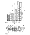
- FIG. 1 shows a top perspective view of a marked with reference numeral 2 housing comprising a housing lower part 4 and a housing upper part 6, which are interconnected.
- the housing 2 has two parallel extending covers, of which only the cover 8 formed by the upper housing part 6 can be seen. Within the cover 8 a plurality of openings 10 are recessed, which allow passage of air through the housing 2.
- Each of the openings 10 is centrally penetrated by a longitudinal web 12 which extends parallel to below the opening located radiator elements 14 and a heat generating PTC heating element 16 covers, which in the sectional view according to FIG. 2 can be seen and a plurality in the longitudinal direction of the longitudinal web 12 successively arranged PTC elements 18 and on both sides adjacent thereto sheet metal strips 20 comprises.
- the opposite metal strips 20 to a PTC heating element 16 are energized with different polarity. Selected metal strips can be extended in a conventional manner laterally over the housing 2 to form contact tongues (see. EP 1 564 503 ).
- the PTC elements 16 with double-sided adjoining radiator elements 14 each form a heating rod 24.
- the lower housing part 4 forms a Gefach 26 for each heating element 24.
- a heating element 24 is arranged in each Gefach 26 and held under bias of a spring described in more detail below, so that the individual layers of the heating element 24, ie the radiator elements 14, the PTC elements 18 and the sheet metal strips 20 provided therebetween under bias abut against each other, so that the heat generated by the PTC element 18 is transmitted with good heat conduction to the radiator element 14 and a safe current input can be made at least from the metal strips 20 to the PTC elements 18.
- all metal strips 20 are led out to the formation of plug contacts the front side of the compartments 26.
- spacers 30 are formed by the lower housing part. These spacers 30 bridge over a web 31 a distance between the compartments 26 and are relative to the outer surface of the housing 2 formed by the cover 2 inwardly offset (see. FIG. 2 ).
- the upper housing part 6 provided in the manner of a housing cover is broken through.
- the housing upper part 6 has only peripherally provided, connected housing cover sections 32, each covering a Gefach 26, connecting transverse webs 34.
- the spacer elements 30 are released by the housing cover portions 32, so that the housing 2 is formed between the individual compartments 26 is substantially single-layered, that is, only the spacer elements 30 includes.
- the transverse webs 34 are formed narrow relative to the length of the housing 2 and preferably leave more than 90% of the total length of the housing 2 between the individual compartments 26 free.
- the webs 31 of the spacer elements 30 have a plurality of longitudinally of the housing 2 successively arranged air passage openings 36 whose flow resistance of the housing 2 passing air flow is adjusted approximately to the flow resistance of the individual radiator elements 14, so that on the air outlet side of the housing 2 by Mixing of the partial flows through the openings 10 on the one hand and through the air passage openings 36 on the other hand in the temperature uniform total flow of exiting air results.
- FIG. 1a shows an alternative embodiment, which substantially the above with reference to FIG. 1 corresponds described.
- the same components are identified by the same reference numerals.
- the main difference of in FIG. 1 A shown embodiment with respect to in FIG. 1 shown is that instead of a single housing cover 6 with a plurality of unit cover connected to a housing cover sections 32, this in the embodiment in FIG. 1 a are provided as separate housing cover segments 38.
- the housing cover segments 38 extend in the present case over the entire length of the housing 2 and are fitted in recesses 40, which are recessed at formed by the lower housing part 4 cross bars 42.
- the respective spacer elements 30 extend in the longitudinal direction of the housing 2 as far as the transverse member 42.
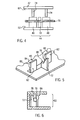
- FIGS. 2 and 3 illustrate a spring means 44, which is formed in the present case only the outer heating element 24 associated. More similar or identically designed spring means may be provided adjacent to further heating elements 24 and / or between two heating elements such that the spring biasing means 44 caused by the elastic biasing force, the layers of adjacent heating elements 24 against each other under bias.
- the spring device 44 has integrally formed on the lower housing part 4 supporting elements 46 which are chamfered end with an inclined surface 48.
- a plurality of support members 46 is formed by the lower housing part 4.
- the lower housing part 4 also forms fixing elements 50 whose active surfaces are parallel to the active surfaces of the support elements 46, ie which extend at right angles to a bottom 52 of the lower housing part.
- the fixing elements 50 are arranged offset relative to the support elements 46.
- the fixing elements 50 are located approximately in the middle between adjacent support elements 46.
- a spring band 54 forming a plastic chord in the sense of the present invention is introduced into the lower housing part 4, which extends substantially over the entire length of the housing 2 , It will the spring band 54 is slightly biased between the fixing member 50 and adjacent support members 46 and thus held in the lower housing part 4.
- spacer ribs 56 are formed on the housing lower part 4, which space the PTC elements 18 of a PTC heating element 16 in the longitudinal direction of the housing 2 from one another.
- the spacer ribs 56 extend in the present case over the entire height of the lower housing part 6 and thus also form a contact surface for the upper housing part 4.
- the fixing elements 50 are arranged in the longitudinal direction of the housing 2 approximately at the height of the spacer ribs 56. In any case, at the height of the PTC elements 18 there are no fixing elements 50. The in FIG.
- the contact elements 58 protrude from the bottom 52 of the lower housing part 4. However, they are not connected end to the housing lower part 4, but cut free via a slot 62, for example, with respect to the cross member 42 or a bearing element 64 which protrudes from the housing bottom at right angles and forms an abutment for the fixing element 50. Due to this configuration, the abutment elements 58 can be pivoted about their feet about an axis which extends parallel to the longitudinal direction of the housing 2.
- the PTC elements 8 are deposited on a retaining rib 66, which likewise protrudes from the bottom 52 of the lower housing part 4 and is provided between the transverse member 42 and the adjacent spacer rib 56 or between adjacent spacer ribs 56. With this retaining rib 66, the PTC elements 18 are also accommodated in the housing 2 at a predetermined distance from the bottom 52 within the receiving space 60.
- the substantially lid-shaped housing upper part 8 has at its the receiving space 60 facing housing cover surface 67 a plurality of approximately at right angles from the housing cover portion 32 projecting, in the cross-sectional view FIG. 2 formed on both sides of a spherical shape, which forms the counter-element to the support elements 46 displacer 68.
- These displacers 68 are integrally formed on the upper housing part 4 formed and - relative to the longitudinal direction of the housing 2 - provided between adjacent support members 46.
- a plurality of spring means 44 are provided in the longitudinal direction of the housing 2, which are each separated by fixing elements 50 with associated bearing elements 64.
- Each of the spring devices 44 shown has over the longitudinal extension of the contact element 58 extending and limited thereto displacement 58, which form a counter element to the contact element and associated, alternately provided for this purpose support members 46.
- the spring band 54 usually runs in one piece over the entire length of the housing 2 ,
- the spring preload generated in this case is forwarded via the contact element 58 to the elements of the heating element 24. Due to the spherical configuration of the displacement element 60 and the contact element 58, the spring force is focused on the central region of the receiving space (in the vertical direction), i. on the area in which the PTC heating elements 16 are located.
- a sufficient electrical contact between the metal strips 20 and the PTC elements 18 of a heating element 24 is effected as well as a sufficient thermal contact between the PTC elements 18 via the metal strips 20 to the radiator elements 14th
- the spring band 54 may be a plastic band.
- a spring device 44 which merely has to bias the elements of a heating element 24 in a single compartment 26, which is adapted precisely to the dimensions of the heating element 24, the spring force exerted by a plastic spring element is sufficient. to achieve a good electrical and thermal contact between the PTC elements 18 and the other elements of the heating element 26.
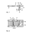
- FIGS. 4 to 6 illustrate an alternative embodiment of a spring means, which is designated for this embodiment by reference numeral 70.
- the spring device 70 has similar to the support member 56 of the previously discussed embodiment, a support member 72 which protrudes from the bottom 52 of the housing base 4 and cooperates with a projecting from the housing cover portion 32 displacement element 74 as a counter element to a formed by a silicone cord 76 spring element between alternating support points elastic bias.
- the support element 72 has an inclined surface 78, through which a funnel-shaped taper for receiving the silicone cord 76 results, which is open at the top and extends between the support element 72 and contact elements 80 at right angles to the bottom 52.
- the abutment elements 80 are formed in cross-section as the contact elements 58 and have in addition to the right angles to the bottom 52 extending rear side in the central region a spherical configuration through which a tapered sliding surface 84 and approximately at mid-height of the receiving space 60, a contact projection 86 is formed which cooperates with a neighboring radiator element 14.
- a support element 72 is provided between adjacent and mutually associated contact elements 80.
- the integrally formed on the housing cover portion 32 displacement elements 74 are in the longitudinal direction at the level of the abutment members 80.
- a subsequent to the sliding surface 84 and extending substantially parallel to the bottom 52 support 88 which is formed by the support member 72 is so in the height direction spaced relative to the bottom 52, that resting on the support 88 silicone cord 76 is located approximately at the height of the abutment protrusion 86 of the contact element 80.
- FIGS. 4 to 6 shown embodiment of a spring device 70 braces only one heating element 24, has been dispensed with the representation, but which may correspond to the heating element 24 according to the previously discussed embodiment.
- the arrangement of the PTC element 18 is such that it is located at mid-height of the receiving space 60.
- the heating element 24 is first introduced into the Gefach. Furthermore, the silicone cord 76 is placed on the support 88, so that the longitudinally extending silicone cord 76 between the rear sides 82 of the abutment elements and the sliding surface 74 of the support member 72 is located.
- the displacement elements 74 act on the rear side 82 of the abutment elements 80 against the silicone cord 76. This is thereby elastically deformed between the alternating support points in the height direction of the receiving space 60.
- the width of the support member 72 may vary depending on the elasticity of the silicone cord.
- the abutment elements 80 of the support element 72 may also overlap in the longitudinal direction or even be formed continuously in the region of the spring device 44.
- FIGS. 6 and 7 show an alternative embodiment with a plastic spring means, which is designated by reference numeral 90 and characterized by two downwardly U-shaped legs, of which a reference element 92 marked counter element is provided with an inclined surface 74 which can slide on a radiator element 14 and transferred to a ubenvorsprung 96.
- the limb of the exemplary embodiment facing away from the radiator element 14 is to be designated as a spring element 98, since it stores the predominant part of the elastic deformation component integrally formed on the housing cover section 32 by injection molding.
- the two legs 92, 98 are connected to one another via a web 100.
- This in FIG. 7 shown upper housing part 4 is manufactured as a one-piece component by means of plastic injection molding. Similar to the investment elements 80 of the in the FIGS.
- the longitudinal sectional view according to FIG. 8 shows on the side of the lower housing part 4, a spring element 98 associated with the supporting element 106, which forms a sliding surface 108.
- a plurality of spring devices 90 and associated support elements 106 are provided on the side of the upper housing part 4. Again, the corresponding spring devices are preferably in the longitudinal direction at the height of the PTC elements 18th
- the elements forming the heating element 24 are inserted into the lower housing part 4.
- the recorded in the Gefach 24 heating rod 24 is set by closing the housing 2 by applying the upper housing part 6 under tension.
- the spring element 98 slides past the sliding surface 108. It will from the sliding surface 108 in the region of its foot, that is bent around a bending axis extending in the longitudinal direction of the housing 2. This bend is transmitted via the web 100, which is also resiliently biased.
- a certain elastic bias also results in the counter-element 92, which is urged against the radiator element 14 as the insertion movement progresses due to the deformation of the spring element 98. In response to this contact force results in a certain elastic deformation of the counter element 92nd
- spring means 70, 90 are preferably associated with each individual Gefach 26 and thus a single heating rod 24 to put the components contained therein under bias.
- snap-in connections are provided in the region of the respective spring device, through which the lower housing part is connected to the upper housing part, so that the upper housing part 6 does not lift from the lower housing part 4.
- the elastic tension of the spring device 70, 90 is secured.
- latching connections not only in the edge region of the housing 4, but also in the transverse direction in the middle thereof, preferably formed immediately adjacent to a Gefach 26.
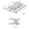
- intermediate walls may be provided between the spacer element 30 and the Gefach, so that a formed for example on the upper housing part 6 locking lug between the partition and the adjacent boundary wall of the Gefaches 26 can enter and lock with a formed on the intermediate wall window opening.
- a corresponding embodiment is in the FIGS. 9 and 10 clarified.
- There said partition of the Gefaches 26 is designated by reference numeral 110.
- An intermediate wall is identified by reference numeral 112.
- the latching opening within this intermediate wall 112 is designated by reference numeral 114.
- a with the housing 2 closed in this locking opening 114 einfedernder locking web is in FIG. 10 denoted by reference numeral 116.
Landscapes
- Engineering & Computer Science (AREA)
- Physics & Mathematics (AREA)
- Thermal Sciences (AREA)
- Chemical & Material Sciences (AREA)
- Combustion & Propulsion (AREA)
- Mechanical Engineering (AREA)
- General Engineering & Computer Science (AREA)
- Resistance Heating (AREA)
- Air-Conditioning For Vehicles (AREA)
- Direct Air Heating By Heater Or Combustion Gas (AREA)
- Baking, Grill, Roasting (AREA)
- Electric Stoves And Ranges (AREA)
Abstract
Description
Die vorliegende Erfindung betrifft eine elektrische Heizvorrichtung mit einem offenen Gehäuse, in dem mehrere PTC-Elemente und daran anliegende Radiatorelemente unter Vorspannung gegeneinander anliegend gehalten sind.The present invention relates to an electric heater having an open case in which a plurality of PTC elements and adjoining radiator elements are biased against each other.
Derartige elektrische Heizvorrichtungen sind als PTC-Zuheizer für Kraftfahrzeuge allgemein bekannt und beispielsweise in der auf die Anmelderin zurückgehenden
Die PTC-Heizelemente haben selbstregelende Eigenschaften. Ihr elektrischer Widerstand nimmt mit höherer Temperatur zu, was bei dem Einsatz von PTC-Heizelementen zur Erwärmung von Luft in einem Kraftfahrzeug den Vorteil mit sich bringt, dass die elektrische Heizvorrichtung nicht überhitzen kann. Andererseits muss aufgrund der selbstregelnden Eigenschaften die von den PTC-Heizelementen erzeugte Wärme effektiv abgeführt werden. Dazu ist zum Einen dafür Sorge zu tragen, dass die von einem PTC-Element erzeugte Wärme zunächst über Wärmeleitung in einer Ebene regelmäßig quer zu den Radiatorelementen abgeleitet wird. Ein PTC-Element, d.h. ein Keramik-Stein ist regelmäßig zwischen zwei Kontaktblechen angeordnet. Diese Anordnung bildet ein PTC-Heizelement aus. Die Kontaktbleche können wiederum bereits Teil des Radiatorelementes sein. Die Radiatorelemente sind aus metallischem Werkstoff mit guter Wärmeleitung ausgebildet und leiten die zunächst über Wärmeleitung in die Radiatorelemente eingebrachte Wärme an die die Radiatorelemente anströmende Luft ab.The PTC heating elements have self-regulating properties. Their electrical resistance increases with higher temperature, which brings with the use of PTC heating elements for heating air in a motor vehicle with the advantage that the electric heater can not overheat. On the other hand, due to the self-regulating properties, the heat generated by the PTC heating elements must be dissipated effectively. For this purpose, on the one hand to ensure that the heat generated by a PTC element is first derived via heat conduction in a plane regularly transverse to the radiator elements. A PTC element, i. a ceramic stone is regularly arranged between two contact plates. This arrangement forms a PTC heating element. The contact plates can in turn already be part of the radiator element. The radiator elements are formed from metallic material with good heat conduction and conduct the heat initially introduced into the radiator elements via heat conduction to the air flowing in the radiator elements.
Im Stand der Technik sind grundlegend verschiedene Konzepte bekannt, wie die oben beschriebene gute elektrische und wärmemäßige Kontaktierung zwischen dem Heizelement und den daran anliegenden Radiatorelementen bewirkt werden kann.In the prior art fundamentally different concepts are known, as the above-described good electrical and thermal contact between the heating element and the adjoining radiator elements can be effected.
So beschreibt die
Bei einer anderen Ausgestaltung gemäß dem zuvor erwähnten gattungsbildenden Stand der Technik bzw. der
Bei der Vorspannung eines Heizblocks in einem Gehäuse sind indes durch das bzw. die Federelemente erhebliche Setzbeträge zu kompensieren. Dementsprechend muss die Feder über einen größeren Federweg die notwendige elastische Vorspannung aufbringen können. Dies führt regelmäßig zu dem Erfordernis einer Feder aus einem Federband, die in der den Heizblock enthaltenen Ebene einen gewissen Raum einnimmt, um die nötige Federkraft über den erforderlichen Federweg zum Ausgleich von Toleranzen bewirken zu können.When biasing a heating block in a housing, however, are to be compensated by the or the spring elements significant amounts. Accordingly, the spring must be able to apply the necessary elastic bias over a longer travel. This regularly leads to the requirement of a spring from a spring band, which occupies a certain amount of space in the heating block contained in order to bring about the necessary spring force over the required travel to compensate for tolerances can.
Auch stellt es häufig ein Problem dar, den Heizblock innerhalb des Gehäuses unter Federvorspannung in dem Gehäuse aufzunehmen. Dies ist insbesondere dann problematisch, wenn zunächst die Elemente des Heizblocks unter Federvorspannung in das noch offene Gehäuse eingesetzt und erst danach das Gehäuse geschlossen wird.Also, it often poses a problem to receive the heater block within the housing under spring bias in the housing. This is particularly problematic when initially the elements of the heating block under spring preload inserted into the still open housing and only then the housing is closed.
Aus der auf die Anmelderin zurückgehenden
Mitunter ist es nämlich erforderlich, die elektrische Heizvorrichtung in einem Bauraum innerhalb des Gehäuses eines Klimamoduls in einem Fahrzeug relativ raumbauend anzuordnen, um die gesamte von der Luft durchsetzte Fläche abzudecken. Die Fläche kann mitunter größer sein, als die für die Heizleistung bei effektivem Einsatz der den Heizblock bildenden Elemente notwendig ist. In diesem Fall muss der Heizblock relativ raumbauend ausgebildet sein, was zu nicht unerheblichen Mehrkosten führt. Zwar kann die Anzahl der PTC-Elemente innerhalb des Heizblocks an die gewünschte Heizleistung angepasst werden. Gleichwohl muss die gesamte Luftdurchtrittsfläche innerhalb des Gehäuses mit PTC-Heizelementen und daran anliegenden Radiatorelementen ausgefüllt werden.Sometimes it is necessary to arrange the electric heater in a space within the housing of a climate module in a vehicle relatively space-building, to cover the entire area interspersed by the air. The area can sometimes be greater than that required for the heating power with effective use of the heating block forming elements. In this case, the heating block must be designed to be relatively space-consuming, resulting in not inconsiderable additional costs. Although the number of PTC elements within the heating block can be adapted to the desired heating power. Nevertheless, the entire air passage area within the housing must be filled with PTC heating elements and adjoining radiator elements.
Abhilfe schafft die aus der
Bei dem aus der
Der vorliegenden Erfindung liegt die Aufgabe zugrunde, eine verbesserte elektrische Heizvorrichtung anzugeben. Dabei will die vorliegende Erfindung eine einfach und kostengünstig herzustellende Lösung als Weiterbildung für eine gattungsgemäße elektrische Heizvorrichtung angeben, bei welcher die PTC-Heizelemente mit den daran anliegenden Radiatorelementen unter Vorspannung gegeneinander anliegen.The present invention has for its object to provide an improved electric heater. In this case, the present invention seeks to provide a simple and inexpensive to manufacture solution as a development of a generic electric heater, in which the PTC heating elements bear with the adjoining radiator elements under bias against each other.
Zur Lösung dieses Problems wird mit der vorliegenden Erfindung eine elektrische Heizvorrichtung mit einem offenem Gehäuse angegeben, in dem wenigstens ein PTC-Heizelement und Radiatorelement unter Vorspannung gehalten sind, wobei das Gehäuse ein Gehäuseoberteil und ein Gehäuseunterteil aufweist, die Öffnungen zum Durchtritt eines die Radiatorelemente anstrahlenden Mediums freilassen. Gemäß der Erfindung hat das Gehäuseunterteil wenigstens ein von seinem Boden abragendes Stützelement. Das Gehäuseoberteil hat ein von seiner Deckelfläche abragendes Gegenelement zu dem Stützelement. Das Stützelement und das Gegenelement wirken beim Schließen des Gehäuses mit einem Federelement aus Kunststoff zusammen, welches zwischen dem Stützelement und dem Gegenelement verspannt ist und so erzeugte elastische Verformungsanteile speichert.To solve this problem, the present invention provides an electric heater having an open case in which at least one PTC heating element and radiator element are biased, the housing having an upper housing part and a lower housing part having openings for passing a radiator element Release media. According to the invention, the lower housing part has at least one projecting from its bottom support member. The upper housing part has a counter-element protruding from its lid surface to the support element. The support member and the counter element act together when closing the housing with a spring element made of plastic, which is clamped between the support member and the counter element and thus stores generated elastic deformation components.
Die erfindungsgemäße Ausgestaltung bietet die Möglichkeit, eine Aufnahme, insbesondere eine Aufnahme für einen einzelnen Heizstab umfassend ein PTC-Heizelement mit je einem seitlich daran anliegenden Radiatorelement in einem Gefach eines Gehäuses für sich aufzunehmen und unter Vorspannung zu setzen, wobei diese Vorspannung durch ein Federelement aus Kunststoff bewirkt wird. Wenngleich ein Federelement aus Kunststoff als zur Verspannung von Wärme erzeugenden und Wärme abgebenden Lagen eines elektrischen Zuheizers der gattungsgemäßen Art als ungeeignet angesehen wurde, haben Untersuchungen der Anmelderin gezeigt, dass solche Federelemente insbesondere bei guter toleranzmäßiger Abstimmung zwischen einer Aufnahme für die wärmeerzeugenden und die wärmeabgebenden Elemente innerhalb des Gehäuses und den Abmessungen dieser wärmeerzeugenden und wärmeabgebenden Elemente die notwendige Verspannung auch durch ein Kunststofffederelement bewirkt werden kann.The embodiment of the invention provides the ability to record a recording, in particular a receptacle for a single heating element comprising a PTC heating element, each with a laterally adjacent thereto radiator element in a Gefach a housing for itself and under bias, said bias by a spring element Plastic is effected. Although a spring element made of plastic as for the stress of heat generating and heat-emitting layers of an electric heater of the generic type was considered unsuitable, investigations by the Applicant have shown that such spring elements in particular with good tolerance vote between a receptacle for the heat-generating and the heat-emitting elements within the housing and the dimensions of these heat-generating and heat-emitting elements, the necessary tension can also be effected by a plastic spring element.
Die Federspannung wird dabei vorzugsweise ausschließlich beim Schließen des Gehäuses bewirkt. Hierbei erfolgt durch Zusammenwirken von Stützelement und Gegenelement eine Verformung des Federelementes, bei welcher in diesem elastische Verformungsanteile erzeugt werden. Aufgrund der Elastizität des Federelementes werden diese Verformungsanteile gespeichert, so dass das Federelement geeignet ist, eventuelle Selbstbeträge sowie thermisch bedingte Änderungen der Dimensionen nachzuführen. Die einzelnen Lagen von Radiatorelement und PTC-Heizelement liegen daher zuverlässig und dauerhaft unter Federvorspannung gegeneinander an.The spring tension is preferably effected only when closing the housing. Here, by interaction of the support element and the counter element, a deformation of the spring element, in which elastic deformation parts are generated in this. Due to the elasticity of the spring element these deformation components are stored, so that the spring element is suitable to track any self-amounts and thermally induced changes in dimensions. The individual layers of radiator element and PTC heating element are therefore reliable and permanently under spring preload against each other.
Gemäß einer bevorzugten Weiterbildung der vorliegenden Erfindung ist das Federelement durch eine sich in Längsrichtung erstreckende Kunststoffsehne gebildet, die durch in ihrer Längsrichtung in alternierender Weise vorgesehene Stütz- und Gegenelemente zur Speicherung elastischer Verformungsanteile verformt ist. In alternierender Weise sind die Stütz- und Gegenelemente dabei vorzugsweise so vorgesehen, dass benachbart zu einem Stützelement in Längsrichtung der Kunststoffsehne zunächst ein Gegenelement folgt. Das Stützelement und das Gegenelement können sich jedoch auch in Längsrichtung teilweise überdecken. Als Längsrichtung wird die Erstreckungsrichtung der einzelnen Lagen eines Heizstapels bzw eines Heizblocks angesehen, d.h. die Längserstreckung beispielsweise des PTC-Heizelementen mit seinen länglichen Blechbändern. Vorzugsweise sind jeweils drei der besagten Elemente zu einer Gruppe zusammengefasst, um das Federelement an vorbestimmter Stelle durch alternierende Stützstellen zu biegen. Die Anordnung erfolgt dabei mit dem Ziel, die Federspannung vornehmlich in demjenigen Längenabschnitt zu erzeugen, in dem sich innerhalb des Gehäuses ein durch die Federspannung einzuspannendes PTC-Element befindet. Im Hinblick auf eine möglichst einfache Gestaltung ist es zu bevorzugen, ein einzelnes Stützelement mittig zwischen zwei benachbarten Gegenelementen vorzusehen, so dass die alternierende Biegung der Kunststoffsehne durch drei Stützstellen erfolgt, von denen die mittlere durch das Stützelement und die beiden äußeren durch die Gegenelemente gebildet sind.According to a preferred embodiment of the present invention, the spring element is formed by a longitudinally extending plastic tendon which is deformed by provided in its longitudinal direction in an alternating manner supporting and counter-elements for storing elastic deformation components. In an alternating manner, the support and counter elements are preferably provided so that adjacent to a support element in the longitudinal direction of the plastic chord initially follows a counter element. However, the support element and the counter element can partially overlap in the longitudinal direction. As a longitudinal direction, the extension direction of the individual layers of a heating stack or a heating block is considered, ie the longitudinal extent, for example, the PTC heating elements with its elongated metal bands. Preferably, in each case three of the said elements are combined to form a group in order to bend the spring element at a predetermined point through alternating support points. The arrangement is carried out with the goal of producing the spring tension primarily in that length section in which a PTC element to be clamped by the spring tension is located inside the housing. With regard to the simplest possible design, it is preferable to provide a single support member centrally between two adjacent counter-elements, so that the alternating bending of the plastic chord takes place by three support points, of which the middle are formed by the support member and the two outer by the counter-elements ,
Gemäß einer bevorzugten Weiterbildung ist die Kunststoffsehne durch ein in das Gehäuse eingelegtes Kunststoffband gebildet. Das Kunststoffband kann verschiedene Querschnittsformen haben. Das Kunststoffband kann ein längliches flaches Band sein. Alternativ ist auch die Ausgestaltung des Kunststoffbandes in Form einer Schnur mit kreisförmigen oder jedem anderen beliebigen Querschnitt denkbar. Das Kunststoffband kann sich über die gesamte Länge des Gehäuses erstrecken. Ebenso gut kann das Band in Segmente unterteilt sein und sich lediglich über eine Teillänge des Gehäuses erstrecken.According to a preferred embodiment, the plastic tendon is formed by a plastic tape inserted into the housing. The plastic band can have different cross-sectional shapes. The plastic band can be an elongated flat band. Alternatively, the design of the plastic strip in the form of a cord with circular or any other arbitrary cross-section is conceivable. The plastic band can extend over the entire length of the housing. As well, the band can be divided into segments and extend only over a partial length of the housing.
Es hat sich überraschenderweise gezeigt, dass auch die Ausbildung eines Kunststoffbandes durch ein weichelastisches Kunststoffelement eine hinreichende elastische Verspannung bewirkt. Als weichelastisches Kunststoffelement kommt beispielsweise ein thermoplastisches Elastomer oder Silikon in Frage. Das Kunststoffband sollte eine hohe Elastizität haben. Im Hinblick auf die Wärmebeständigkeit sind auch Kautschuke als weichelastische Kunststoffe zur Ausbildung des Kunststoffbands denkbar. Das Kunststoffband muss allerdings nicht ausschließlich aus entsprechenden weichelastischen Kunststoffen gebildet sein. Es kann auch einen Kern, beispielsweise aus einer Faser enthalten. Die Zugabe von Füllstoffen ist denkbar.It has surprisingly been found that the formation of a plastic strip by a flexible plastic element causes a sufficient elastic tension. As a flexible plastic element is for example a thermoplastic elastomer or silicone in question. The plastic band should have a high elasticity. With regard to heat resistance, rubbers are also conceivable as soft-elastic plastics for forming the plastic strip. However, the plastic band does not have to be formed exclusively from corresponding soft elastic plastics. It may also contain a core, for example of a fiber. The addition of fillers is conceivable.
Gemäß einer alternativen Ausgestaltung ist die Kunststoffsehne einteilig an dem Gehäuseunterteil und/oder dem Gehäuseoberteil angespritzt. Es hat sich gezeigt, dass eine entsprechende Kunststoffsehne bereits mit den üblicherweise zur Ausbildung von Kunststoffgehäusen verwendeten Kunststoffen erstellt werden kann. Dementsprechend kann das Gehäuse insgesamt aus einem einheitlichen Werkstoff mittels Spritzgießen hergestellt werden. Denkbar ist allerdings auch, das Anspritzen einer Kunststoffsehne durch Umspritzen mit einer anderen Komponente. So kann eine Kunststoffsehne aus einem Kunststoff mit hoher Elastizität als Einlegeteil in ein Spritzgießwerkzeug eingelegt werden, welches zur Ausbildung des Gehäuseunterteils und/oder des Gehäuseoberteils verwendet wird. Danach muss eine einteilig an dem Gehäuseteil angespritzte Kunststoffsehne nicht zwangsläufig stoffidentisch mit dem Gehäuseteil ausgebildet sein.According to an alternative embodiment, the plastic tendon is integrally molded onto the housing lower part and / or the upper housing part. It has been shown that a corresponding plastic tendon can already be created with the plastics usually used to form plastic housings. Accordingly, the housing can be made entirely of a uniform material by means of injection molding. It is also conceivable, however, the injection of a plastic tendon by molding with another component. Thus, a plastic tendon made of a plastic with high elasticity can be inserted as an insert in an injection mold, which is used to form the lower housing part and / or the upper housing part. After that, one piece on the housing part molded plastic chord not necessarily be formed material identical to the housing part.
Eine gute Verspannung des PTC-Heizelementes mit daran anliegenden Radiatorelementen wird beispielsweise dadurch geschaffen, dass die Kunststoffsehne etwa auf mittlerer Höhe des Aufnahmeraumes in dem geschlossenen Gehäuse vorgesehen ist. Der Aufnahmeraum wird dabei zwischen den einander gegenüberliegenden Innenflächen von Gehäuseunterteil und Gehäuseoberteil, d.h. zwischen dem Gehäuseboden und der Deckelfläche des Gehäuseoberteils begrenzt. Die Deckelfläche ist dabei die innere Fläche des Gehäuseoberteils. Die Kunststoffsehne ist nicht nur vorzugsweise etwa auf mittlerer Höhe des Gehäuseraumes vorgesehen, sondern bevorzugt auf diesen Bereich im wesentlichen beschränkt. Die Kunststoffsehne erstreckt sich daher bevorzugt lediglich über einen mittleren Bereich der Höhe des Gehäuseraumes, vorzugsweise in einer Höhe entsprechend 7 bis 15 % der Höhe des Aufnahmeraumes. Auf diese Weise kann die von der Kunststoffsehne bewirkte Federvorspannung effektiv zur Verspannung des PTC-Heizelementes mit daran anliegenden Radiatorelementen genutzt werden.Good clamping of the PTC heating element with adjoining radiator elements is created, for example, by providing the plastic tendon approximately at the middle height of the receiving space in the closed housing. The receiving space is thereby between the opposite inner surfaces of the lower housing part and the upper housing part, i. limited between the housing bottom and the top surface of the housing top. The cover surface is the inner surface of the upper housing part. The plastic tendon is not only preferably provided approximately at mid-height of the housing space, but preferably limited to this area substantially. The plastic tendon therefore preferably extends only over a central region of the height of the housing space, preferably at a height corresponding to 7 to 15% of the height of the receiving space. In this way, caused by the plastic tendon spring preload can be effectively used to clamp the PTC heating element with adjoining radiator elements.
Gemäß einer bevorzugten Weiterbildung weist das Gehäuseoberteil oder das Gehäuseunterteil ein einteilig daran angeformtes Anlageelement auf. Durch dieses Anlageelement wird die durch das Federelement bewirkte Vorspannung in den geschichteten Aufbau bestehend aus wenigstens einem PTC-Element und wenigstens einem Radiatorelement eingebracht. Das Anlageelement vermittelt dementsprechend die Federkraft an den geschichteten Aufbau. Das Anlageelement ist verschwenkbar gegenüber demjenigen Gehäuseteil gelagert, an dem es einteilig ausgebildet ist. Die Verschwenkachse erstreckt sich dabei parallel zu der Längsrichtung des Gehäuses, d.h. der Längserstreckung des PTC-Heizelementes. Vorzugsweise befindet sich die Schwenkachse nahe oder in der Ebene des Bodens des Gehäuseunterteils bzw. der Deckelfläche des Gehäuseoberteils. Jedenfalls ragen die Anlageelemente bevorzugt frei von den entsprechenden Flächenabschnitten von Gehäuseoberteil bzw. Gehäuseunterteil ab, so dass deren Verschwenkbarkeit um die besagte Schwenkachse nicht durch Anbindung an Seitenwände von Gehäuseoberteil bzw. Gehäuseunterteil behindert wird.According to a preferred development, the upper housing part or the lower housing part has an abutment element formed integrally thereon. By this contact element caused by the spring element bias in the layered structure consisting of at least one PTC element and at least one radiator element is introduced. The contact element accordingly conveys the spring force to the layered structure. The contact element is pivotally mounted relative to that housing part on which it is integrally formed. The pivot axis extends parallel to the longitudinal direction of the housing, i. the longitudinal extent of the PTC heating element. Preferably, the pivot axis is close to or in the plane of the bottom of the housing base or the cover surface of the housing upper part. In any case, the abutment elements preferably protrude freely from the corresponding surface sections of the upper housing part or lower housing part, so that their pivotability about the said pivot axis is not obstructed by connection to side walls of the upper housing part or lower housing part.
Gemäß einer bevorzugten Weiterbildung der vorliegenden Erfindung hat das Anlageelement auf der dem Federelement abgewandten Seite eine geneigte Gleitfläche. Diese Gleitfläche vereinfacht den Einbau von PTC-Heizelement und Radiatorelement in das Gehäuse. Der Einbau insbesondere eines Heizstabes bewirkt eine gewisse Dehnung der Anlageelemente in Richtung auf das Federelement. Die Gleitfläche endet dabei beispielsweise in etwa auf mittlerer Höhe des Gehäuseraumes zur Übertragung der Federkraft in einem Anlagevorsprung. Dieser Anlagevorsprung liegt üblicherweise an einem der Radiatorelemente an. Aufgrund der zuvor erwähnten Ausgestaltung wird das Anlageelement beim Einbringen des PTC-Heizelementes und der daran anliegenden Radiatorelemente in das Gehäuse in Grenzen in Richtung auf das Stützelement vorgespannt. Das insbesondere zwischen dem Stützelement und dem Anlageelementen befindliche Federelement drängt das Anlageelement beispielsweise im mittleren Bereich gegen das benachbarte Radiatorelement, wodurch dieses unter Vorspannung gegen das PTC-Heizelement und dieses wiederum gegen das andere Radiatorelement unter Vorspannung gehalten wird.According to a preferred embodiment of the present invention, the contact element on the side facing away from the spring element has an inclined sliding surface. This sliding surface simplifies the installation of PTC heating element and radiator element in the housing. Of the Installation of a particular heating rod causes a certain elongation of the contact elements in the direction of the spring element. The sliding surface ends, for example, approximately at mid-height of the housing space for transmitting the spring force in a plant projection. This investment projection is usually on one of the radiator elements. Due to the aforementioned embodiment, the contact element is biased when introducing the PTC heating element and the adjoining radiator elements in the housing in limits in the direction of the support element. The particular located between the support element and the contact elements spring element urges the contact element, for example in the central region against the adjacent radiator element, whereby this is biased against the PTC heating element and this in turn against the other radiator element under bias.
Zur leichteren Einbringung des Kunststoffbandes in das Gehäuse wird gemäß einer bevorzugten Weiterbildung der vorliegenden Erfindung vorgeschlagen, die der Gleitfläche abgewandte Rückseite der Anlageelemente mit sich im wesentlichen rechtwinklig zu dem Boden erstreckender Ausrichtung vorzusehen und eine zu den Anlageelementen zeigende Schrägfläche des Stützelementes in Richtung auf die Anlageelemente geneigt auszubilden. Durch diese geneigte Ausgestaltung wird zusammen mit der Rückseite der Anlageelemente eine sich trichterförmig verjüngende Aufnahme für das Kunststoffband gebildet. Einerseits wird hierdurch das Einlegen des Kunststoffbandes vereinfacht. Andererseits nähert sich das Kunststoffband beim Einlegen in das Gehäuse durch Abgleiten an der Schrägfläche der Rückseite des bzw. der Anlageelemente an und wird dadurch zwangsläufig in die richtige Position gebracht, um die Federkraft vorzugsweise in etwa mittig gegen das Radiatorelement zu übertragen.For easier insertion of the plastic strip into the housing, it is proposed according to a preferred embodiment of the present invention to provide the sliding surface facing away from the rear side of the contact elements extending substantially at right angles to the ground extending orientation and pointing to the contact elements inclined surface of the support element in the direction of the contact elements inclined to train. By this inclined configuration, a funnel-shaped tapered receptacle for the plastic strip is formed together with the back of the contact elements. On the one hand, this simplifies the insertion of the plastic strip. On the other hand, the plastic tape approaches when inserted into the housing by sliding on the inclined surface of the back of the or the contact elements and is thereby inevitably brought into the correct position to transmit the spring force preferably approximately centrally against the radiator element.
Diese Endlage des Kunststoffbands wird in einer bevorzugten Weiterbildung der vorliegenden Erfindung sicher eingenommen, bei welcher die Schrägfläche in eine Auflage für das Kunststoffband übergeht, wobei diese Auflage sich im wesentlichen parallel zu dem Boden erstreckt. Die Auflage dient als Anlagefläche für das Kunststoffband und positioniert selbiges in Höhenrichtung in dem Gehäuseraum. Diese Auflage verhindert im übrigen, dass sich eine durch Kompression in Einbringrichtung des Gegenelementes elastisch verformende Kunststofffeder in Richtung auf das Gehäuseunterteil verlagert und sich so der aufzubringenden Verspannung entzieht. Die Auflage kann zwischen benachbarten Gegenelementen eingeschlossen sein. Es sind aber auch Ausgestaltungen denkbar, bei denen sich die Auflage und das Gegenelement in Längsrichtung des Gehäuses teilweise oder vollständig überdecken.This end position of the plastic tape is safely taken in a preferred embodiment of the present invention, in which the inclined surface merges into a support for the plastic strip, said support extending substantially parallel to the bottom. The support serves as a contact surface for the plastic tape and positioned selbiges in the height direction in the housing space. This edition prevents the rest, that displaced by compression in the insertion direction of the counter element elastically deforming plastic spring in the direction of the lower housing part and thus escapes the applied tension. The support may be enclosed between adjacent counter-elements. But there are also embodiments conceivable in which the edition and cover the counter element in the longitudinal direction of the housing partially or completely.
Gemäß einer weiteren bevorzugten Ausgestaltung der vorliegenden Erfindung ist eine elastische Verformungsanteile auf das PTC-Element übertragende Anlagefläche vorgesehen. Diese Anlagefläche wird regelmäßig durch das Anlageelement gebildet. Die Anlagefläche ist zur Übertragung der elastischen Verformungsanteile in Wirkungsrichtung der Verspannung beweglich. Die Anlagefläche ist vorzugsweise lediglich über eine geringe Höhe des gesamten Aufnahmeraumes wirksam, d.h. liegt lediglich an einem geringen Höhenabschnitt, beispielsweise des Radiatorelementes an. Die Anlagefläche kann in Höhenrichtung an jeder beliebigen Position innerhalb des Aufnahmeraumes vorgesehen sein. Die Anlagefläche sollte indes auf gleicher Höhe wie das ihr zugeordnete PTC-Element vorgesehen sein. Die Anlagefläche muss nicht zwingend die Verformungsanteile direkt auf das PTC-Element. übertragen. Vielmehr ist auch eine mittelbare Übertragung der Verformungsanteile auf das PTC-Element über andere Schichten des geschichteten Aufbaus, beispielsweise das Radiatorelement oder zwischen der Anlagefläche und dem PTC-Element vorgesehene Blechbänder denkbar. Mit der Anlagefläche und der im wesentlichen höhengleichen Anordnung des zugeordneten PTC-Elementes soll sichergestellt werden, dass die von der Feder erzeugte Federkraft bestmöglich auf das PTC-Element übertragen wird.According to a further preferred embodiment of the present invention, an elastic deformation components on the PTC element transmitting contact surface is provided. This contact surface is formed regularly by the contact element. The contact surface is movable to transmit the elastic deformation components in the direction of action of the tension. The abutment surface is preferably effective only over a small height of the entire receiving space, i. is only on a small height section, for example, the radiator element. The contact surface can be provided in the height direction at any position within the receiving space. The contact surface should, however, be provided at the same height as the associated PTC element. The contact surface does not necessarily have the deformation components directly on the PTC element. transfer. Rather, indirect transfer of the deformation components to the PTC element via other layers of the layered structure, for example the radiator element or sheet metal strips provided between the contact surface and the PTC element, is also conceivable. With the contact surface and the substantially level arrangement of the associated PTC element is to ensure that the spring force generated by the spring is best transmitted to the PTC element.
Es hat sich indes als bevorzugt herausgestellt, die Anlagefläche und/oder das PTC-Element in Höhenrichtung des Gehäuses außermittig und nahe der Lufteintrittsseite der elektrischen Heizvorrichtung vorzusehen. Die Lufteintrittsseite ist dabei diejenige Seite durch welche die zu erwärmende Luft in das offene Gehäuse eintritt. Vorzugsweise befindet sich das PTC-Element unmittelbar unterhalb einer die dazu vorgesehene Öffnung ausbildenden Abdeckung des Gehäuseoberteils bzw. des Gehäuseunterteils. Die Weiterbildung kann auch für sich erfindungswesentlich und in einem konventionellen elektrischen Zuheizer verwirklicht sein, bei welcher der Schichtaufbau bzw. der Heizstab unter Vorspannung einer metallischen Feder gehalten ist. Denkbar ist auch die außermittige Anordnung des PTC-Elementes in einem Positionsrahmen, der ganz oder teilweise von den sich gegenüberliegenden Blechbändern bedeckt ist. Die Weiterbildung lässt sich dabei von der Vorstellung leiten, dass das in dem Gehäuse aufgenommene PTC-Element eine geringere Höhe als das dem PTC-Element zugeordnete Radiatorelement hat, wobei letzteres die Höhe des Aufnahmeraumes innerhalb des Gehäuses bestimmt.It has, however, been found preferable to provide the contact surface and / or the PTC element off-center in the height direction of the housing and close to the air inlet side of the electric heating device. The air inlet side is the side through which the air to be heated enters the open housing. Preferably, the PTC element is located directly below a cover of the housing upper part or the housing lower part which forms the opening provided for this purpose. The development can also be realized according to the invention and in a conventional electric heater in which the layer structure or the heating element is held under bias of a metallic spring. It is also conceivable eccentric arrangement of the PTC element in a position frame which is completely or partially covered by the opposing metal strips. The development can be guided by the idea that the PTC element accommodated in the housing has a lower height than the radiator element assigned to the PTC element, the latter determining the height of the receiving space within the housing.
Die entsprechende Anordnung des PTC-Elementes außermittig wird insbesondere dadurch erreicht, dass an dem Gehäuseunterteil oder dem Gehäuseoberteil eine wenigstens einem PTC-Element zugeordnete Halterippe ausgebildet ist, die sich jedenfalls abschnittsweise in Längsrichtung des Gehäuses erstreckt und durch welche das PTC-Element nahe der Lufteintrittsfläche vorgesehen ist. Die besagte Halterippe hat aber vorzugsweise nicht nur die Funktion das PTC-Element in Höhenrichtung außermittig innerhalb des Aufnahmeraumes anzuordnen. Vielmehr dient die Halterippe auch der Versteifung des Gehäuseteils und durchsetzt dieses vorzugsweise durchgehend in Längsrichtung.The corresponding arrangement of the PTC element off-center is achieved in particular by the fact that at least one PTC element associated retaining rib is formed on the housing lower part or the housing top, which extends at least partially in the longitudinal direction of the housing and through which the PTC element near the air inlet surface is provided. However, the said retaining rib preferably has not only the function of arranging the PTC element in the height direction off-center within the receiving space. Rather, the retaining rib also serves to stiffen the housing part and penetrates this preferably continuously in the longitudinal direction.
Bei einer bevorzugten Ausgestaltung weist das Federelement vorzugsweise zusammen mit dem Gegenelement eine zu dem Boden des Gehäuseunterteils offene U-förmige Ausgestaltung auf. In dieser Ausgestaltung bildet vorzugsweise ein sich im wesentlich parallel zu dem Gegenelement erstreckender Schenkel des Federelementes eine Anlagefläche zur Anlage gegen das benachbarte Radiatorelement aus, welches unter Vorspannung dagegen anliegt und eine Federkraft auf den Heizstab ausübt. Das Federelement weist vorzugsweise neben den beiden in Richtung auf den Boden des Gehäuseunterteils abragenden Schenkel einen diese verbindenden Steg auf, der bei geschlossenem Gehäuse zwischen der mittleren Höhe des Gehäuseraumes und der Deckelfläche vorgesehen ist. Dieser Steg dient als Federsteg und hat vorzugsweise eine in Richtung auf den Gehäusedeckel gekrümmte Ausgestaltung, so dass der Steg zur Erzeugung einer Federvorspannung sich nach oben wölbend verformt werden kann.In a preferred embodiment, the spring element preferably has, together with the counter element, a U-shaped configuration open to the bottom of the housing lower part. In this embodiment, preferably forms a substantially parallel to the counter element extending leg of the spring element from a contact surface for abutment against the adjacent radiator element, which bears against it under bias and exerts a spring force on the heating element. The spring element preferably has, in addition to the two protruding in the direction of the bottom of the lower housing part legs a connecting web, which is provided with the housing closed between the middle height of the housing space and the lid surface. This web serves as a spring bar and preferably has a curved in the direction of the housing cover design, so that the web to produce a spring preload can be deformed upwardly bulging.
Gemäß einer bevorzugten Weiterbildung der Erfindung ist ein sich im wesentlichen parallel zu dem Gegenelement erstreckender Federschenkel stoffschlüssig an dem Gehäusedeckel angeschlossen. Die parallele Erstreckung zwischen Gegenelement und Federschenkel ergibt sich insbesondere bei einem unbelasteten Federelement, d.h. vor dem Zusammenbau des Gehäuses. Der Federschenkel erstreckt sich bei der zuvor genannten Ausgestaltung vorzugsweise in etwa rechtwinklig zu dem Gehäusedeckel.According to a preferred embodiment of the invention, a substantially parallel to the counter element extending spring leg is firmly connected to the housing cover. The parallel extension between counter-element and spring leg is obtained in particular with an unloaded spring element, i. before assembling the housing. The spring leg preferably extends in the above-mentioned embodiment approximately at right angles to the housing cover.
Vorzugsweise bildet bei einem einteilig an dem Gehäusedeckel angeformten Federschenkel das Gegenelement das zuvor beschriebene Anlageelement aus, welches einteilig und verschwenkbar an dem Gehäuseteil verbunden ist und welches vorzugsweise eine Anlagefläche zur Übertragung der elastischen Verformungsanteile auf das PTC-Element ausbildet. Dabei wird davon ausgegangen, dass sich das Gegenelement beim Schließen des Gehäuses und Anlegen der Anlagefläche beispielsweise an das Radiatorelement jedenfalls geringfügig verformt. Die überwiegende Verformung und deren elastische Speicherung wird allerdings von dem Federschenkel und/oder dem den Federschenkel mit dem Gegenelement verbundenen Steg aufgenommen und gespeichert.Preferably, in an integrally formed on the housing cover spring leg, the counter-element of the above-described contact element, which is integrally and pivotally connected to the housing part and which preferably forms a contact surface for transmitting the elastic deformation components on the PTC element. It is assumed that the counter element when closing the housing and applying the contact surface, for example, to the radiator element in any case slightly deformed. However, the predominant deformation and its elastic storage is absorbed and stored by the spring leg and / or the spring leg connected to the counter element web.
Gemäß einer weiteren bevorzugten Ausgestaltung der vorliegenden Erfindung bildet das Stützelement eine rampenförmige Vorspannfläche aus, gegen welche das Federelement beim Schließen des Gehäuses zur Erzeugung elastischer Verformungsanteile abgleitet.According to a further preferred embodiment of the present invention, the support element forms a ramp-shaped biasing surface, against which the spring element slides when closing the housing to produce elastic deformation components.
In einer bevorzugten Weiterbildung wird die elektrische Heizvorrichtung dadurch weitergebildet, dass das Gehäuse mehrere Gefache ausbildet, wobei in einzelnen Gefachen jeweils Heizstäbe, gebildet aus einem PTC-Heizelement mit beidseitig daran anliegenden Radiatorelementen aufgenommen und deren Elemente unter Vorspannung gegeneinander anliegend gehalten sind. Das PTC-Heizelement umfasst in an sich bekannter Weise wenigstens ein PTC-Element, welches vorzugsweise zwischen zwei elektrisch leitenden Blechbändern aufgenommen, vorzugsweise geklemmt ist. Jeweils an der Außenseite des PTC-Heizelemtes liegen die Radiatorelemente daran an. Die Radiatorelemente liegen in dem Luftstrom der zu erwärmenden Luft frei der durch Öffnungen des offenen Gehäuses strömt. Ein Gefach des Gehäuses ist jeweils derart dimensioniert, dass lediglich ein Heizstab, d.h. eine Einheit aus PTC-Heizelementen mit daran anliegenden Radiatorelementen in dem Gefach aufgenommen werden kann. Dabei sind die Heizstäbe jeweils für sich in eigenen Gefachen gehalten. Die den Heizstab bildenden Elemente sind jeweils unter Vorspannung gegeneinander anliegend in dem Gefach gehalten.In a preferred embodiment, the electrical heating device is further developed in that the housing forms a plurality of compartments, in each compartment each heating rods formed from a PTC heating element with both sides adjacent thereto radiator elements and their elements are held under bias against each other. The PTC heating element comprises, in a manner known per se, at least one PTC element, which is preferably accommodated, preferably clamped, between two electrically conductive sheet metal strips. Respectively on the outside of the PTC Heizelemtes the radiator elements abut it. The radiator elements are exposed in the air flow of the air to be heated, which flows through openings of the open housing. A compartment of the housing is in each case dimensioned such that only one heating element, i. a unit of PTC heating elements with adjoining radiator elements can be accommodated in the compartment. The heating elements are each held in separate compartments. The heating element forming elements are each held under bias against each other fitting in the Gefach.
Diese Lösung bietet den Vorteil, dass eine die Elemente in einem Gefach vorspannende Feder lediglich eine geringe Toleranz ausgleichen muss. Dies bietet die Möglichkeit, eine relativ einfache, kostengünstig herzustellende Federanordnung jedem Gefach zuzuordnen, um die in dem Gefach gehaltenen Elemente unter Vorspannung gegeneinander anzulegen. Dabei befinden sich die aus Kunststoff gebildeten Federelemente üblicherweise verteilt im Inneren des Gehäuses und sind jeweils den einzelnen Gefachen zugeordnet. Ein Federelement kann lediglich die Elemente eines Heizstabs in einem einzelnen Gefach gegeneinander verspannen. Es können aber auch Federelemente aus Kunststoff vorgesehen sein, die die Elemente der Heizstäbe in zwei benachbarten Gefachen gegeneinander unter Vorspannung halten.This solution has the advantage that a spring biasing the elements in a Gefach must compensate only a small tolerance. This offers the possibility to assign a relatively simple, inexpensive to manufacture spring assembly each Gefach to put the elements held in the Gefach elements under bias against each other. In this case, the spring elements formed of plastic are usually distributed in the interior of the housing and are each associated with the individual compartments. A spring element can only clamp the elements of a heating element in a single Gefach against each other. But it can also be provided spring elements made of plastic, which hold the elements of the heating elements in two adjacent compartments against each other under bias.
Zu jedem Gefach ist vorzugsweise ein die Elemente des Heizstabes unter Vorspannung setzendes Federelement vorgesehen. Jedenfalls befindet sich aber zumindest ein Federelement mit Abstand von einem Rand des Gehäuses innerhalb desselben.For each Gefach a preferably the elements of the heating element under bias voltage setting spring element is provided. In any case, there is at least one spring element at a distance from an edge of the housing within the same.
Gemäß einer bevorzugten Weiterbildung der vorliegenden Erfindung sind in den einzelnen Gefachen jeweils für sich aufgenommene Heizstäbe die Heizstufen der elektrischen Heizvorrichtung. Mit anderen Worten bildet jedes einzelne in einem separaten Gefach aufgenommene Heizelement jeweils eine Heizstufe aus. Gemäß einer weiteren bevorzugten Ausgestaltung der vorliegenden Erfindung sind sämtliche PTC-Heizelemente und die daran anliegenden Radiatorelemente der elektrischen Heizvorrichtung jeweils zu Heizstäben zusammengefasst und in separaten Gefachen vorgesehen. Bei dieser bevorzugten Ausgestaltung der vorliegenden Erfindung wird die elektrische Heizvorrichtung ausschließlich aus Heizstäben gebildet, die jeweils für sich in einem eigenständigen Gefach aufgenommen sind.According to a preferred embodiment of the present invention, the heating stages of the electric heating device are in each case for themselves recorded heating elements in the individual compartments. In other words, each individual heating element accommodated in a separate compartment forms a respective heating stage. According to a further preferred embodiment of the present invention, all PTC heating elements and the adjacent thereto radiator elements of the electric heater are each combined to form heating elements and provided in separate compartments. In this preferred embodiment of the present invention, the electric heater is formed solely of heating rods, which are each taken up in a separate Gefach.
Gemäß einer weiteren bevorzugten Weiterbildung der vorliegenden Erfindung, die die Verwirklichung einer elektrischen Heizvorrichtung mit relativ großen Abmessungen bei relativ geringen Gestehungskosten ermöglicht, sind benachbarte Gefache mit Gehäusedeckelabschnitten verschlossen, die an einem Gehäuseunterteil befestigt sind und zwischen sich ein durch das Gehäuseunterteil gebildetes Abstandselement freigeben, welches benachbarte Gefache verbindet. Danach bildet allein das Gehäuseunterteil das Abstandselement aus. Dieses kann einen beliebigen Abstand zwischen benachbarten Gefachen einstellen. Das Abstandselement selber ist vorzugsweise nicht mit einem Gehäusedeckelabschnitt verbunden. Vielmehr liegt das Abstandselement ganz oder teilweise zwischen den Gehäusedeckelabschnitten frei. In einer Schnittansicht durch das Gehäuse ergeben sich somit zweiteilig verschlossene Abschnitte dort, wo Gefache mit Gehäusedeckelabschnitten verschlossen sind, und einteilige Abschnitte dort, wo ein Abstandselement zwischen benachbarten Gefachen vorgesehen ist. Gehäusedeckelabschnitte bei dieser bevorzugten Ausgestaltung können jeweils für sich separat ausgebildete Gehäusedeckelsegmente sein, die lediglich einem Gefach zugeordnet sind, um dieses zu verschließen. Gehäusedeckelabschnitte können aber auch an einem einheitlich ausgeformten Gehäusedeckel vorgesehen sein, welcher im Bereich der Abstandselemente lediglich über dünne Stege, vorzugsweise randseitig vorgesehene Stege Brücken bildet, die benachbarte, vorzugsweise sämtliche Gehäusedeckelabschnitte miteinander verbinden. Jedenfalls kann aber im Bereich der Abstandselemente Material für den Gehäusedeckel eingespart werden, wodurch die Kosten für die Erstellung des Gehäuses und damit der elektrischen Heizvorrichtung verringert werden können. Die Abstandselemente können in Querrichtung, d.h. quer zur Längserstreckung der einzelnen Heizstäbe beliebig breit ausgebildet sein, um eine möglichst große elektrische Heizvorrichtung bei geringen Gestehungskosten zu schaffen.According to a further preferred embodiment of the present invention, which allows the realization of an electric heater with relatively large dimensions at relatively low production costs, adjacent compartments are closed with housing cover sections which are attached to a lower housing part and release between them formed by the lower housing part spacer which connecting neighboring compartments. Thereafter, only the lower housing part forms the spacer element. This can set any distance between adjacent compartments. The spacing element itself is preferably not connected to a housing cover section. Rather, the spacer element is completely or partially exposed between the housing cover sections. In a sectional view through the housing thus result in two-part sealed sections where compartments are closed with housing cover sections, and one-piece sections where a spacer is provided between adjacent compartments. Housing cover sections in this preferred embodiment may each be separately formed housing cover segments, which are assigned only to a Gefach to close this. However, housing cover sections may also be provided on a uniformly shaped housing cover which forms bridges in the area of the spacer elements only via thin webs, preferably webs provided at the edge, which connect adjacent, preferably all housing cover sections with one another. In any case, but in the area of the spacer material be saved for the housing cover, whereby the cost of creating the housing and thus the electric heater can be reduced. The spacer elements can be designed to be arbitrarily wide in the transverse direction, ie transversely to the longitudinal extent of the individual heating elements, in order to create the largest possible electric heating device at low production costs.
Zur Verbesserung der Festigkeit wird gemäß einer bevorzugten Weiterbildung der vorliegenden Erfindung vorgeschlagen, das Abstandselement gegenüber einem Boden des Gehäuseunterteils in Dickenrichtung der elektrischen Heizvorrichtung nach innen versetzt auszubilden. Die Abstandselemente sind dabei vorzugsweise als relativ dünne Stege ausgeformt, die benachbarte Gefache miteinander verbinden. Dünne Stege werden insbesondere bei einer Ausgestaltung verwirklicht, bei der die Stege lediglich eine Dicke von 3 % bis 15 % der Gesamtdicke des Gehäuses einnehmen. Vorzugsweise befinden sich die Stege in etwa auf mittlerer Höhe des Gehäuses.To improve the strength, it is proposed according to a preferred development of the present invention to form the spacer element offset in relation to a bottom of the housing lower part in the thickness direction of the electric heater inwardly. The spacers are preferably formed as relatively thin webs that connect adjacent compartments together. Thin webs are in particular realized in an embodiment in which the webs occupy only a thickness of 3% to 15% of the total thickness of the housing. Preferably, the webs are located approximately at mid-height of the housing.
Zur Vergleichmäßigung des Luftwiderstandes über die Luftdurchtrittsfläche des offenen Gehäuses wird gemäß einer weiteren bevorzugten Ausgestaltung der vorliegenden Erfindung vorgeschlagen, an dem Abstandselement Luftdurchtrittsöffnungen zu versehen. Die Luftdurchtrittsöffnungen weisen einen Strömungswiderstand auf, der in etwa dem Strömungswiderstand der Heizstäbe entspricht. Jedenfalls sollte der durch die Luftdurchtrittsöffnungen erlaubte Strömungsweg dem Luftstrom keinen erheblich geringeren Widerstand als benachbart hierzu vorgesehene Heizstäbe entgegensetzen. Andernfalls wäre zu befürchten, dass der Hauptteil der Luft durch die Abstandselemente hindurchströmt, ohne effektiv erwärmt zu werden.To even out the air resistance over the air passage surface of the open housing is proposed according to a further preferred embodiment of the present invention, to provide at the spacer air passage openings. The air passage openings have a flow resistance which corresponds approximately to the flow resistance of the heating elements. In any case, the flow path allowed through the air passage openings should not oppose the air flow with significantly lower resistance than heating rods provided adjacent thereto. Otherwise, it would be feared that the majority of the air will flow through the spacers without being effectively heated.
Weitere Einzelheiten und Vorteile der vorliegenden Erfindung ergeben sich aus der nachfolgenden Beschreibung in Verbindung mit der Zeichnung. In dieser Zeichnung zeigen:
- Fig. 1
- eine perspektivische Draufsicht auf ein erstes Ausführungsbeispiel einer elektri- schen Heizvorrichtung;
- Fig. 1a
- eine Ansicht gemäß
Figur 1 für ein gegenüber dem Ausführungsbeispiel nachFigur 1 abgewandeltes Ausführungsbeispiel einer elektrischen Heizvorrichtung; - Fig. 2
- eine Schnittansicht entlang der Linie II-II gemäß der Darstellung in
Figur 1 ;
- Fig. 3
- eine Schnittansicht entlang der Linie III-III gemäß
Figur 2 ; - Fig. 4
- eine Seitenansicht auf eine Federeinrichtung eines zu den
Figuren 2 und 3 alter- nativen Ausführungsbeispiels; - Fig. 5
- Teile der in
Figur 4 - Fig. 6
- die in
Figuren 4 und 5 - Fig. 7
- den gehäuseoberseitigen Teil eines weiteren Ausführungsbeispiels einer Feder- einrichtung;
- Fig. 8
- die in
Figur 7 verdeutlichte Federeinrichtung bei geschlossenem Gehäuse; - Fig. 9
- eine perspektivische Draufsicht auf einen Teil eines Gehäuseunterteils eines wei- teres Ausführungsbeispiels der vorliegenden Erfindung und
- Fig. 10
- eine Schnittansicht entlang der Linie X-X gemäß der Darstellung in
Figur 9
- Fig. 1
- a top perspective view of a first embodiment of an electric heater;
- Fig. 1a
- a view according to
FIG. 1 for a comparison with the embodiment according toFIG. 1 modified embodiment of an electric heater; - Fig. 2
- a sectional view taken along the line II-II as shown in FIG
FIG. 1 ;
- Fig. 3
- a sectional view taken along the line III-III according to
FIG. 2 ; - Fig. 4
- a side view of a spring means one of the
FIGS. 2 and 3 alternative embodiment; - Fig. 5
- Parts of in
FIG. 4 illustrated spring device in perspective view; - Fig. 6
- in the
FIGS. 4 and 5 clarified spring device with closed housing; - Fig. 7
- the housing upper side part of another embodiment of a spring device;
- Fig. 8
- in the
FIG. 7 clarified spring device with the housing closed; - Fig. 9
- a perspective top view of a part of a housing lower part of a further embodiment of the present invention and
- Fig. 10
- a sectional view taken along line XX as shown in FIG
FIG. 9
Die
Jede der Öffnungen 10 ist mittig von einem Längssteg 12 durchsetzt, der sich parallel zu unterhalb der Öffnung befindlichen Radiatorelementen 14 erstreckt und ein Wärme erzeugendes PTC-Heizelement 16 abdeckt, welches in der Schnittansicht gemäß
Die PTC-Elemente 16 mit beidseitig daran anliegenden Radiatorelementen 14 bilden jeweils einen Heizstab 24 aus. Das Gehäuseunterteil 4 bildet zu jedem Heizstab 24 ein Gefach 26 aus.The
Wie der Schnittansicht gemäß
Zwischen den Gefachen 26 sind durch das Gehäuseunterteil 4 Abstandselemente 30 ausgebildet. Diese Abstandselemente 30 überbrücken über einen Steg 31 einen Abstand zwischen den Gefachen 26 und befinden sich relativ zu der durch die Abdeckung 8 gebildeten Außenfläche des Gehäuses 2 nach innen versetzt (vgl.
Die Stege 31 der Abstandselemente 30 weisen mehrere in Längsrichtung des Gehäuses 2 hintereinander angeordnete Luftdurchtrittsöffnungen 36 auf, deren Strömungswiderstand einer das Gehäuse 2 durchsetzenden Luftströmung in etwa an den Strömungswiderstand der einzelnen Radiatorelemente 14 angepasst ist, so dass sich auf der Luftaustrittsseite des Gehäuses 2 ein durch Mischen der Teilströme durch die Öffnungen 10 einerseits und durch die Luftdurchtrittsöffnungen 36 andererseits in der Temperatur vergleichmäßigter Gesamtstrom an austretender Luft ergibt.The
Die
Die
Die Federeinrichtung 44 hat an dem Gehäuseunterteil 4 angeformte Stützelemente 46, die endseitig mit einer Schrägfläche 48 angefast ausgebildet sind. In Längsrichtung des Gehäuses 2 ist eine Vielzahl von Stützelementen 46 durch das Gehäuseunterteil 4 ausgebildet. In größeren, gleichfalls regelmäßigen Abständen bildet das Gehäuseunterteil 4 darüber hinaus Fixierelemente 50 aus, deren Wirkflächen parallel zu den Wirkflächen der Stützelemente 46 sind, d.h. die sich rechtwinklig zu einem Boden 52 des Gehäuseunterteils erstrecken. Die Fixierelemente 50 sind relativ zu den Stützelementen 46 versetzt angeordnet. Die Fixierelemente 50 befinden sich etwa mittig zwischen benachbarten Stützelementen 46. Zwischen die Stützelemente 46 und die Fixierelemente 50 wird ein eine Kunststoffsehne im Sinne der vorliegenden Erfindung ausbildendes Federband 54 in das Gehäuseunterteil 4 eingebracht, das sich im wesentlichen über die gesamte Länge des Gehäuses 2 erstreckt. Dabei wird das Federband 54 zwischen dem Fixierelement 50 und benachbarten Stützelementen 46 leicht vorgespannt und damit in dem Gehäuseunterteil 4 gehalten.The
Von dem Boden 52 abragend sind an dem Gehäuseunterteil 4 Abstandsrippen 56 ausgebildet, die die PTC-Elemente 18 eines PTC-Heizelementes 16 in Längsrichtung des Gehäuses 2 voneinander beabstanden. Die Abstandsrippen 56 erstrecken sich vorliegend über die gesamte Höhe des Gehäuseunterteils 6 und bilden damit auch eine Anlagefläche für das Gehäuseoberteil 4 aus. Die Fixierelemente 50 sind in Längsrichtung des Gehäuses 2 in etwa auf Höhe der Abstandsrippen 56 angeordnet. Jedenfalls auf Höhe der PTC-Elemente 18 befinden sich keine Fixierelemente 50. Das in
Die Anlageelemente 58 ragen zwar von dem Boden 52 des Gehäuseunterteils 4 ab. Sie sind jedoch endseitig nicht mit dem Gehäuseunterteil 4 verbunden, sondern über einen Schlitz 62 freigeschnitten, so beispielsweise gegenüber dem Querholm 42 oder einem Lagerelement 64, welches von dem Gehäuseboden rechtwinklig abragt und ein Widerlager für das Fixierelement 50 bildet. Aufgrund dieser Ausgestaltung können die Anlageelemente 58 um ihren Fuß um eine Achse verschwenkt werden, die sich parallel zu der Längsrichtung des Gehäuses 2 erstreckt.Although the
Die PTC-Elemente 8 sind auf einer Halterippe 66 abgelegt, die ebenfalls von dem Boden 52 des Gehäuseunterteils 4 abragt und zwischen dem Querholm 42 und der randnahen Abstandrippe 56 bzw. zwischen benachbarten Abstandsrippen 56 vorgesehen ist. Mit dieser Halterippe 66 befinden sich auch die PTC-Elemente 18 in einem vorbestimmten Abstand von dem Boden 52 innerhalb des Aufnahmeraums 60 in dem Gehäuse 2 aufgenommen.The
Das im wesentlichen deckelförmig ausgebildete Gehäuseoberteil 8 hat an seiner dem Aufnahmeraum 60 zugewandten Gehäusedeckelfläche 67 mehrere in etwa rechtwinklig von dem Gehäusedeckelabschnitt 32 abragende, in der Querschnittsansicht gemäß
Wie die Draufsicht auf das offene Gehäuseunterteil 4 gemäß
Zum Verspannen der einzelnen in einem Gefach 26 gehaltenen Lagen eines Heizstabes 24 wird beim Schließen des Gehäuses 2 durch Aufbringen des Gehäuseoberteils 6 auf das Gehäuseunterteil 4 das Federband 54 zwischen benachbarten Stützelementen 46 und dem dazwischen vorgesehenen Verdrängerelement 68 elastisch gebogen. Die hierbei erzeugte Federvorspannung wird über das Anlageelement 58 an die Elemente des Heizstabes 24 weitergeleitet. Durch die ballige Ausgestaltung des Verdrängerelementes 60 und des Anlageelementes 58 wird die Federkraft auf den mittleren Bereich des Aufnahmeraumes (in Höhenrichtung) fokussiert, d.h. auf denjenigen Bereich, in dem die PTC-Heizelemente 16 befindlich sind. Damit wird eine hinreichende elektrische Kontaktierung zwischen den Blechbändern 20 und den PTC-Elementen 18 eines Heizstabes 24 bewirkt sowie eine hinreichende thermische Kontaktierung zwischen den PTC-Elementen 18 über die Blechbänder 20 zu den Radiatorelementen 14.To clamp the individual held in a Gefach 26 layers of a
Das Federband 54 kann ein Kunststoffband sein. Alternativ ist auch das Einbringen eines Federstahlbandes möglich. Es hat sich aber gezeigt, dass bei einer Federeinrichtung 44, die lediglich die Elemente eines Heizstabes 24 in einem einzigen, hinsichtlich der Dimension genau auf die Abmessungen des Heizstabes 24 angepassten Gefach 26 unter Vorspannung gesetzt werden müssen, die von einem Kunststofffederelement ausgeübte Federkraft ausreicht, um eine gute elektrische und thermische Kontaktierung zwischen den PTC-Elementen 18 und den übrigen Elementen des Heizstabes 26 zu erreichen.The
Die
Die Federeinrichtung 70 hat ähnlich des Stützelement 56 des zuvor diskutierten Ausführungsbeispiels ein Stützelement 72, welches von dem Boden 52 des Gehäuseunterteils 4 abragt und mit einem von dem Gehäusedeckelabschnitt 32 abragenden Verdrängerelement 74 als Gegenelement zusammenwirkt, um ein durch eine Silikonschnur 76 gebildetes Federelement zwischen alternierenden Stützstellen elastisch vorzuspannen.The spring device 70 has similar to the
Das Stützelement 72 hat hierzu eine Schrägfläche 78, durch welche sich eine nach oben offene und zwischen dem Stützelement 72 und Anlageelementen 80 mit sich rechtwinklig zu dem Boden 52 ersteckenden Rückseiten 82 eine trichterförmige Verjüngung zur Aufnahme der Silikonschnur 76 ergibt. Die Anlageelemente 80 sind im Querschnitt wie die Anlageelemente 58 ausgebildet und haben neben der sich rechtwinklig zu dem Boden 52 erstreckenden Rückseite im mittleren Bereich eine ballige Ausgestaltung, durch welche eine abgeschrägte Gleitfläche 84 und in etwa auf mittlerer Höhe des Aufnahmeraumes 60 ein Anlagevorsprung 86 gebildet ist, der mit einem benachbarten Radiatorelement 14 zusammenwirkt.For this purpose, the
In Längsrichtung der Silikonschnur 76 ist zwischen benachbarten und einander zugeordneten Anlageelementen 80 jeweils ein Stützelement 72 vorgesehen. Die an dem Gehäusedeckelabschnitt 32 angeformten Verdrängerelemente 74 befinden sich in Längsrichtung auf Höhe der Anlageelemente 80. Eine sich an die Gleitfläche 84 anschließende und sich im wesentlichen parallel zu dem Boden 52 erstreckende Auflage 88, die durch das Stützelement 72 gebildet wird, ist derart in Höhenrichtung relativ zu dem Boden 52 beabstandet, dass die auf der Auflage 88 aufliegende Silikonschnur 76 sich in etwa auf Höhe des Anlagevorsprungs 86 des Anlageelementes 80 befindet.In the longitudinal direction of the
Auch das in den
Zur Montage wird zunächst der Heizstab 24 in das Gefach eingebracht. Des weiteren wird die Silikonschnur 76 auf die Auflage 88 aufgelegt, so, dass sich die in Längsrichtung erstreckende Silikonschnur 76 zwischen den Rückseiten 82 der Anlageelemente und der Gleitfläche 74 des Stützelementes 72 befindet.For assembly, the
Durch Schließen des Gehäusedeckelabschnitts 32 wirken die Verdrängerelemente 74 auf der Rückseite 82 der Anlageelemente 80 gegen die Silikonschnur 76. Diese wird hierdurch zwischen den alternierenden Stützstellen in Höhenrichtung des Aufnahmeraumes 60 elastisch verformt. Die Breite des Stützelementes 72 kann abhängig von der Elastizität der Silikonschnur variieren. Auch die Anlageelemente 80 des Stützelementes 72 können sich in Längsrichtung überlappen oder gar im Bereich der Federeinrichtung 44 durchgängig ausgebildet sein.By closing the
Die
Die Längsschnittansicht gemäß
Bei der Montage werden zunächst die den Heizstab 24 bildenden Elemente in das Gehäuseunterteil 4 eingelegt. Der in dem Gefach 24 aufgenommene Heizstab 24 wird durch Schließen des Gehäuses 2 durch Aufbringen des Gehäuseoberteils 6 unter Vorspannung gesetzt. Dabei gleitet zunächst das Federelement 98 an der Gleitfläche 108 vorbei. Es wird von der Gleitfläche 108 im Bereich seines Fußes, d.h. um eine sich in Längsrichtung des Gehäuses 2 erstreckende Biegeachse gebogen. Diese Biegung wird über den Steg 100 übertragen, der ebenfalls elastisch vorgespannt wird. Eine gewisse elastische Vorspannung ergibt sich auch in dem Gegenelement 92, welches bei fortschreitender Einbringbewegung durch die Verformung des Federelementes 98 gegen das Radiatorelement 14 gedrängt wird. Als Reaktion auf diese Anlagekraft ergibt sich eine gewisse elastische Verformung des Gegenelementes 92.During assembly, first the elements forming the
Durch an sich bekannte Rastnasen wird schließlich das Gehäuseoberteil 6 mit dem zugehörigen Gehäuseunterteil 4 verbunden.By per se known locking lugs, the
Die in den
- 22
- Gehäusecasing
- 44
- GehäuseunterteilHousing bottom
- 66
- GehäuseoberteilHousing top
- 88th
- Abdeckungcover
- 1010
- Öffnungopening
- 1212
- Längssteglongitudinal web
- 1414
- Radiatorelementradiator element
- 1616
- PTC-HeizelementPTC heating element
- 1818
- PTC-ElementPTC element
- 2020
- Blechbandmetal strip
- 2424
- Heizstabheater
- 2626
- GefachGefach
- 3030
- Abstandselementspacer
- 3131
- Stegweb
- 3232
- GehäusedeckelabschnittCover section
- 3434
- Querstegcrosspiece
- 3636
- LuftdurchtrittsöffnungAir passage opening
- 3838
- GehäusedeckelsegmentCover segment
- 4040
- Aussparungrecess
- 4242
- Querholmtransverse spar
- 4444
- Federeinrichtungspring means
- 4646
- Stützelementsupport element
- 4848
- Schrägflächesloping surface
- 5050
- Fixierelementfixing
- 5252
- Bodenground
- 5454
- Federbandspring band
- 5656
- Abstandsrippespacer rib
- 5858
- Anlageelementcontact element
- 5959
- Anlageflächecontact surface
- 6060
- Aufnahmeraumaccommodation space
- 6262
- Schlitzslot
- 6464
- Lagerelementbearing element
- 6666
- Halterippeholding rib
- 6767
- GehäusedeckelflächeCover surface
- 6868
- Verdrängerelement/GegenelementDisplacement / counter element
- 7070
- Federeinrichtungspring means
- 7272
- Stützelementsupport element
- 7474
- Verdrängerelementdisplacement
- 7676
- Silikonschnursilicone cord
- 7878
- Schrägflächesloping surface
- 8080
- Anlageelementcontact element
- 8282
- Rückseiteback
- 8484
- Gleitflächesliding surface
- 8686
- Auflagevorsprungbearing protrusion
- 8888
- Auflageedition
- 9090
- Federeinrichtungspring means
- 9292
- Gegenelementcounter-element
- 9696
- Anlagevorsprungabutment projection
- 9898
- Federelementspring element
- 100100
- Stegweb
- 102102
- Längsschlitzlongitudinal slot
- 104104
- Längsschlitzlongitudinal slot
- 106106
- Stützelementsupport element
- 108108
- Gleitflächesliding surface
- 110110
- Trennwandpartition wall
- 112112
- Zwischenwandpartition
- 114114
- Rastöffnunglatching opening
- 116116
- Raststeglatching web
Claims (16)
- An electric heating device, in particular for use as an auxiliary heater for motor vehicles, having an open housing (2), in which at least one PTC heating element (16) and radiator elements (14) are held under pretension, said housing (2) comprising an upper housing component (6) and a lower housing component (4) defining openings (10) through which a medium impinging on the radiator elements can flow, characterized in that
the lower housing component (4) comprises at least one support element (46; 72; 106) projecting from the bottom thereof and the upper housing component (6) comprises a counterelement (68; 74; 92) to said support element (46; 72; 106), said counterelement (68; 74; 92) projecting from the cover surface (67) of said upper housing component (6), and said support element (46; 72; 106) and said counterelement (68; 74; 92) cooperating, during closing of the housing (2), with a spring element (54; 76; 98), which is made of plastic and tensioned between the support element (46; 72; 106) and the counterelement (68; 74; 92) so as to store the elastic deformation components produced. - The electric heating device according to claim 1, characterized in that the spring element (54; 76; 98) is defined by a plastic cord extending in the longitudinal direction of the housing (2) and deformed by support and counterelements (46, 72, 106; 68, 74, 92), which are provided in an alternating mode of arrangement in the longitudinal direction of said plastic cord, so as to store elastic deformation components.
- The electric heating device according to claim 1 or 2, characterized in that the plastic cord is defined by a plastic band (54; 76) placed inside the housing.
- The electric heating device according to claim 3, characterized in that the plastic band (54; 76) is formed of a soft-elastic plastic material.
- The electric heating device according to one of the claims 1, 2 or 4, characterized in that the plastic cord is formed integrally with the lower housing component (4) and/or the upper housing component (6) by means of injection moulding.
- The electric heating device according to one of the preceding claims, characterized by a contact element (58; 80; 92) which projects from the lower housing component (4) or from the upper housing component (6) and by means of which the pretension is introduced, said contact element (58; 80; 92) being formed integrally with the housing component (4, 6) and pivotable relative to said housing component (4, 6) about an axis extending parallel to the PTC heating element (16).
- The electric heating device according to claim 5, characterized in that the contact element (58; 80; 92) defines an inclined sliding surface (84) on the side facing away from the spring element (54; 76).
- The electric heating device according to claim 7, characterized in that the back of the contact element (80) facing away from the sliding surface (84) extends substantially perpendicular to the bottom (52), and that an oblique surface (78) of the support element (72) inclined towards the contact element (80) is inclined towards the contact element (80).
- The electric heating device according to claim 8, characterized in that the oblique surface (78) merges with a support (88) for the plastic band (54; 76), said support (88) extending substantially parallel to the bottom (52).
- The electric heating device according to one of the preceding claims, characterized by a contact surface (86, 96) transmitting the elastic deformation components to the PTC element (18), and/or that said PTC element (18) are provided eccentrically in the height direction of the housing.
- The electric heating device according to claim 10, characterized in that the lower housing component (4) and/or the upper housing component (6) define a holding rib (56), which is associated with at least a PTC element (18) and extends, at least sectionwise, in the longitudinal direction of the housing (2) and by means of which the PTC element is arranged close to the air admission area of the housing (2).
- The electric heating device according to one of the preceding claims, characterized in that the spring element (98) has, together with the counterelement (92), a U-shaped configuration which is open towards the bottom (52) of the lower housing component (4).
- The electric heating device according to claim 12, characterized in that, in the closed condition of the housing (2), a web (100) of the spring element is provided between the middle of the height of the housing space and a cover surface, said web (100) connecting two legs (92, 98) which project towards the bottom (52) of the lower housing component (4).
- The electric heating device according to claim 13, characterized in that a spring leg (98) which extends substantially parallel to the counterelement (92) is connected to the housing cover (32) in a substance-to substance bond.
- The electric heating device according to one of the claims 12 to 14, characterized in that the contact element is defined by the counterelement (92).
- The electric heating device according to one of the claims 12 to 15, characterized in that the support element (106) defines a ramp-shaped pretensioning surface on which the spring element (98) slides during closing of the housing (2).
Priority Applications (4)
| Application Number | Priority Date | Filing Date | Title |
|---|---|---|---|
| ES09008078T ES2367580T3 (en) | 2009-06-19 | 2009-06-19 | ELECTRICAL HEATING DEVICE. |
| AT09008078T ATE520555T1 (en) | 2009-06-19 | 2009-06-19 | ELECTRIC HEATING DEVICE |
| EP09008078A EP2266823B1 (en) | 2009-06-19 | 2009-06-19 | Electric heating device |
| KR1020100058264A KR101317847B1 (en) | 2009-06-19 | 2010-06-18 | Electric heating device |
Applications Claiming Priority (1)
| Application Number | Priority Date | Filing Date | Title |
|---|---|---|---|
| EP09008078A EP2266823B1 (en) | 2009-06-19 | 2009-06-19 | Electric heating device |
Publications (2)
| Publication Number | Publication Date |
|---|---|
| EP2266823A1 EP2266823A1 (en) | 2010-12-29 |
| EP2266823B1 true EP2266823B1 (en) | 2011-08-17 |
Family
ID=41120183
Family Applications (1)
| Application Number | Title | Priority Date | Filing Date |
|---|---|---|---|
| EP09008078A Not-in-force EP2266823B1 (en) | 2009-06-19 | 2009-06-19 | Electric heating device |
Country Status (4)
| Country | Link |
|---|---|
| EP (1) | EP2266823B1 (en) |
| KR (1) | KR101317847B1 (en) |
| AT (1) | ATE520555T1 (en) |
| ES (1) | ES2367580T3 (en) |
Families Citing this family (5)
| Publication number | Priority date | Publication date | Assignee | Title |
|---|---|---|---|---|
| CN103009963B (en) * | 2013-01-05 | 2015-04-01 | 东风汽车公司 | Automobile heater installing device with anti-theft function and installation method thereof |
| FR3062898B1 (en) * | 2017-02-14 | 2021-06-18 | Valeo Systemes Thermiques | ELECTRICAL HEATING DEVICE INCLUDING A DEVICE FOR LIMITING THE MOVEMENT OF THE HEATING ELEMENTS |
| FR3078147B1 (en) * | 2018-02-19 | 2021-10-29 | Valeo Systemes Thermiques | FRAMEWORK OF AN ELECTRIC HEATING DEVICE INCLUDING AT LEAST ONE HEATING ELEMENT HOLDING DEVICE |
| KR101973581B1 (en) * | 2018-12-06 | 2019-09-02 | 덕일산업 주식회사 | Heater For tightly Contacts Internal Components Using A Contact Member |
| KR101998811B1 (en) * | 2018-12-06 | 2019-10-01 | 덕일산업 주식회사 | Heater for internal parts to tightly contact |
Family Cites Families (8)
| Publication number | Priority date | Publication date | Assignee | Title |
|---|---|---|---|---|
| US5256857A (en) * | 1990-08-22 | 1993-10-26 | Texas Instruments Incorporated | Finned PTC air heater assembly for heating an automotive passenger compartment |
| JP2891109B2 (en) * | 1994-07-08 | 1999-05-17 | 株式会社デンソー | Heating equipment |
| DE10118600C2 (en) * | 2001-04-12 | 2003-05-28 | Webasto Thermosysteme Gmbh | Electric heater |
| DE10143852B4 (en) * | 2001-09-06 | 2008-04-17 | Webasto Ag | radiator |
| ATE382139T1 (en) * | 2004-02-10 | 2008-01-15 | Catem Gmbh & Co Kg | ELECTRIC HEATING DEVICE FOR LOW HEIGHTS |
| ATE399664T1 (en) | 2004-07-28 | 2008-07-15 | Behr France Rouffach Sas | HEATING ARRANGEMENT WITH A HEATING ELEMENT, PARTICULARLY FOR A MOTOR VEHICLE |
| DE102005026238A1 (en) | 2005-06-07 | 2006-12-14 | Catem Gmbh & Co. Kg | Electric heater |
| EP2017103B1 (en) * | 2007-07-18 | 2016-05-04 | Eberspächer catem GmbH & Co. KG | Electric heating device |
-
2009
- 2009-06-19 AT AT09008078T patent/ATE520555T1/en active
- 2009-06-19 ES ES09008078T patent/ES2367580T3/en active Active
- 2009-06-19 EP EP09008078A patent/EP2266823B1/en not_active Not-in-force
-
2010
- 2010-06-18 KR KR1020100058264A patent/KR101317847B1/en not_active IP Right Cessation
Also Published As
| Publication number | Publication date |
|---|---|
| KR101317847B1 (en) | 2013-10-15 |
| ES2367580T3 (en) | 2011-11-04 |
| ATE520555T1 (en) | 2011-09-15 |
| KR20100136945A (en) | 2010-12-29 |
| EP2266823A1 (en) | 2010-12-29 |
Similar Documents
| Publication | Publication Date | Title |
|---|---|---|
| EP1564503B1 (en) | Electical heating device of low height | |
| EP2025541B1 (en) | Heating element of an electric heating device | |
| EP1931176B1 (en) | An electrical heating device and its method of manufacturing | |
| EP1432287B1 (en) | Electrical heating device with housing | |
| EP3079442B1 (en) | Electrical heating device and frame for same | |
| EP3493650B1 (en) | Electric heating device | |
| EP1731340B1 (en) | Electric heating device | |
| DE19706199B4 (en) | Electric heating device, in particular for a motor vehicle | |
| EP2266823B1 (en) | Electric heating device | |
| DE2706464C2 (en) | Electric switch | |
| DE19911547A1 (en) | Electric heater for motor vehicle has heating block clamped in frame by at least one spring element that forms integral part of heating block and is arranged between two heating elements | |
| EP2407327B1 (en) | Electric heating device, in particular additional motor vehicle heating and motor vehicle air conditioning device | |
| DE29719639U1 (en) | Device for heating interiors, in particular motor vehicles | |
| DE10333451B4 (en) | Apparatus for receiving ceramic heating elements and method for producing such | |
| DE69607900T2 (en) | Support rail for electrical connection module and an electrical connection module for snap fastening to such a support rail | |
| EP3557155B1 (en) | Electric heating device | |
| DE202018101686U1 (en) | Energy guiding chain and divider for this purpose | |
| EP2268103B1 (en) | Electric heating device | |
| EP1429017B1 (en) | Heating flange | |
| DE102012011903B4 (en) | Electric heater | |
| DE19732010A1 (en) | Electric heating device, in particular for a motor vehicle | |
| DE102016201726A1 (en) | battery assembly | |
| EP0932010B1 (en) | Heat exchanger | |
| EP2157270A1 (en) | Heat isolating profile for flame retardant constructions and composite profile for doors, windows and facades | |
| DE10121568A1 (en) | Electric heating device with heating block held in a frame |
Legal Events
| Date | Code | Title | Description |
|---|---|---|---|
| PUAI | Public reference made under article 153(3) epc to a published international application that has entered the european phase |
Free format text: ORIGINAL CODE: 0009012 |
|
| 17P | Request for examination filed |
Effective date: 20091106 |
|
| AK | Designated contracting states |
Kind code of ref document: A1 Designated state(s): AT BE BG CH CY CZ DE DK EE ES FI FR GB GR HR HU IE IS IT LI LT LU LV MC MK MT NL NO PL PT RO SE SI SK TR |
|
| AX | Request for extension of the european patent |
Extension state: AL BA RS |
|
| GRAP | Despatch of communication of intention to grant a patent |
Free format text: ORIGINAL CODE: EPIDOSNIGR1 |
|
| GRAS | Grant fee paid |
Free format text: ORIGINAL CODE: EPIDOSNIGR3 |
|
| GRAA | (expected) grant |
Free format text: ORIGINAL CODE: 0009210 |
|
| AK | Designated contracting states |
Kind code of ref document: B1 Designated state(s): AT BE BG CH CY CZ DE DK EE ES FI FR GB GR HR HU IE IS IT LI LT LU LV MC MK MT NL NO PL PT RO SE SI SK TR |
|
| REG | Reference to a national code |
Ref country code: GB Ref legal event code: FG4D Free format text: NOT ENGLISH |
|
| REG | Reference to a national code |
Ref country code: CH Ref legal event code: EP |
|
| REG | Reference to a national code |
Ref country code: IE Ref legal event code: FG4D Free format text: LANGUAGE OF EP DOCUMENT: GERMAN |
|
| REG | Reference to a national code |
Ref country code: DE Ref legal event code: R096 Ref document number: 502009001107 Country of ref document: DE Effective date: 20111020 |
|
| REG | Reference to a national code |
Ref country code: ES Ref legal event code: FG2A Ref document number: 2367580 Country of ref document: ES Kind code of ref document: T3 Effective date: 20111104 |
|
| REG | Reference to a national code |
Ref country code: NL Ref legal event code: VDEP Effective date: 20110817 |
|
| LTIE | Lt: invalidation of european patent or patent extension |
Effective date: 20110817 |
|
| PG25 | Lapsed in a contracting state [announced via postgrant information from national office to epo] |
Ref country code: FI Free format text: LAPSE BECAUSE OF FAILURE TO SUBMIT A TRANSLATION OF THE DESCRIPTION OR TO PAY THE FEE WITHIN THE PRESCRIBED TIME-LIMIT Effective date: 20110817 Ref country code: IS Free format text: LAPSE BECAUSE OF FAILURE TO SUBMIT A TRANSLATION OF THE DESCRIPTION OR TO PAY THE FEE WITHIN THE PRESCRIBED TIME-LIMIT Effective date: 20111217 Ref country code: NL Free format text: LAPSE BECAUSE OF FAILURE TO SUBMIT A TRANSLATION OF THE DESCRIPTION OR TO PAY THE FEE WITHIN THE PRESCRIBED TIME-LIMIT Effective date: 20110817 Ref country code: NO Free format text: LAPSE BECAUSE OF FAILURE TO SUBMIT A TRANSLATION OF THE DESCRIPTION OR TO PAY THE FEE WITHIN THE PRESCRIBED TIME-LIMIT Effective date: 20111117 Ref country code: PT Free format text: LAPSE BECAUSE OF FAILURE TO SUBMIT A TRANSLATION OF THE DESCRIPTION OR TO PAY THE FEE WITHIN THE PRESCRIBED TIME-LIMIT Effective date: 20111219 Ref country code: LT Free format text: LAPSE BECAUSE OF FAILURE TO SUBMIT A TRANSLATION OF THE DESCRIPTION OR TO PAY THE FEE WITHIN THE PRESCRIBED TIME-LIMIT Effective date: 20110817 Ref country code: SE Free format text: LAPSE BECAUSE OF FAILURE TO SUBMIT A TRANSLATION OF THE DESCRIPTION OR TO PAY THE FEE WITHIN THE PRESCRIBED TIME-LIMIT Effective date: 20110817 |
|
| PG25 | Lapsed in a contracting state [announced via postgrant information from national office to epo] |
Ref country code: GR Free format text: LAPSE BECAUSE OF FAILURE TO SUBMIT A TRANSLATION OF THE DESCRIPTION OR TO PAY THE FEE WITHIN THE PRESCRIBED TIME-LIMIT Effective date: 20111118 Ref country code: CY Free format text: LAPSE BECAUSE OF FAILURE TO SUBMIT A TRANSLATION OF THE DESCRIPTION OR TO PAY THE FEE WITHIN THE PRESCRIBED TIME-LIMIT Effective date: 20110817 Ref country code: LV Free format text: LAPSE BECAUSE OF FAILURE TO SUBMIT A TRANSLATION OF THE DESCRIPTION OR TO PAY THE FEE WITHIN THE PRESCRIBED TIME-LIMIT Effective date: 20110817 Ref country code: SI Free format text: LAPSE BECAUSE OF FAILURE TO SUBMIT A TRANSLATION OF THE DESCRIPTION OR TO PAY THE FEE WITHIN THE PRESCRIBED TIME-LIMIT Effective date: 20110817 Ref country code: PL Free format text: LAPSE BECAUSE OF FAILURE TO SUBMIT A TRANSLATION OF THE DESCRIPTION OR TO PAY THE FEE WITHIN THE PRESCRIBED TIME-LIMIT Effective date: 20110817 |
|
| REG | Reference to a national code |
Ref country code: IE Ref legal event code: FD4D |
|
| PG25 | Lapsed in a contracting state [announced via postgrant information from national office to epo] |
Ref country code: CZ Free format text: LAPSE BECAUSE OF FAILURE TO SUBMIT A TRANSLATION OF THE DESCRIPTION OR TO PAY THE FEE WITHIN THE PRESCRIBED TIME-LIMIT Effective date: 20110817 Ref country code: IE Free format text: LAPSE BECAUSE OF FAILURE TO SUBMIT A TRANSLATION OF THE DESCRIPTION OR TO PAY THE FEE WITHIN THE PRESCRIBED TIME-LIMIT Effective date: 20110817 Ref country code: SK Free format text: LAPSE BECAUSE OF FAILURE TO SUBMIT A TRANSLATION OF THE DESCRIPTION OR TO PAY THE FEE WITHIN THE PRESCRIBED TIME-LIMIT Effective date: 20110817 |
|
| PG25 | Lapsed in a contracting state [announced via postgrant information from national office to epo] |
Ref country code: RO Free format text: LAPSE BECAUSE OF FAILURE TO SUBMIT A TRANSLATION OF THE DESCRIPTION OR TO PAY THE FEE WITHIN THE PRESCRIBED TIME-LIMIT Effective date: 20110817 Ref country code: EE Free format text: LAPSE BECAUSE OF FAILURE TO SUBMIT A TRANSLATION OF THE DESCRIPTION OR TO PAY THE FEE WITHIN THE PRESCRIBED TIME-LIMIT Effective date: 20110817 |
|
| PLBE | No opposition filed within time limit |
Free format text: ORIGINAL CODE: 0009261 |
|
| STAA | Information on the status of an ep patent application or granted ep patent |
Free format text: STATUS: NO OPPOSITION FILED WITHIN TIME LIMIT |
|
| PG25 | Lapsed in a contracting state [announced via postgrant information from national office to epo] |
Ref country code: DK Free format text: LAPSE BECAUSE OF FAILURE TO SUBMIT A TRANSLATION OF THE DESCRIPTION OR TO PAY THE FEE WITHIN THE PRESCRIBED TIME-LIMIT Effective date: 20110817 |
|
| 26N | No opposition filed |
Effective date: 20120521 |
|
| PG25 | Lapsed in a contracting state [announced via postgrant information from national office to epo] |
Ref country code: HR Free format text: LAPSE BECAUSE OF FAILURE TO SUBMIT A TRANSLATION OF THE DESCRIPTION OR TO PAY THE FEE WITHIN THE PRESCRIBED TIME-LIMIT Effective date: 20120328 |
|
| REG | Reference to a national code |
Ref country code: DE Ref legal event code: R097 Ref document number: 502009001107 Country of ref document: DE Effective date: 20120521 |
|
| BERE | Be: lapsed |
Owner name: EBERSPACHER CATEM G.M.B.H. & CO. KG Effective date: 20120630 |
|
| PGFP | Annual fee paid to national office [announced via postgrant information from national office to epo] |
Ref country code: ES Payment date: 20120625 Year of fee payment: 4 |
|
| PG25 | Lapsed in a contracting state [announced via postgrant information from national office to epo] |
Ref country code: MC Free format text: LAPSE BECAUSE OF NON-PAYMENT OF DUE FEES Effective date: 20120630 |
|
| PG25 | Lapsed in a contracting state [announced via postgrant information from national office to epo] |
Ref country code: MK Free format text: LAPSE BECAUSE OF FAILURE TO SUBMIT A TRANSLATION OF THE DESCRIPTION OR TO PAY THE FEE WITHIN THE PRESCRIBED TIME-LIMIT Effective date: 20110817 |
|
| PG25 | Lapsed in a contracting state [announced via postgrant information from national office to epo] |
Ref country code: BE Free format text: LAPSE BECAUSE OF NON-PAYMENT OF DUE FEES Effective date: 20120630 |
|
| PG25 | Lapsed in a contracting state [announced via postgrant information from national office to epo] |
Ref country code: BG Free format text: LAPSE BECAUSE OF FAILURE TO SUBMIT A TRANSLATION OF THE DESCRIPTION OR TO PAY THE FEE WITHIN THE PRESCRIBED TIME-LIMIT Effective date: 20111117 |
|
| PG25 | Lapsed in a contracting state [announced via postgrant information from national office to epo] |
Ref country code: MT Free format text: LAPSE BECAUSE OF FAILURE TO SUBMIT A TRANSLATION OF THE DESCRIPTION OR TO PAY THE FEE WITHIN THE PRESCRIBED TIME-LIMIT Effective date: 20110817 |
|
| PG25 | Lapsed in a contracting state [announced via postgrant information from national office to epo] |
Ref country code: HR Free format text: LAPSE BECAUSE OF FAILURE TO SUBMIT A TRANSLATION OF THE DESCRIPTION OR TO PAY THE FEE WITHIN THE PRESCRIBED TIME-LIMIT Effective date: 20110817 |
|
| REG | Reference to a national code |
Ref country code: CH Ref legal event code: PL |
|
| GBPC | Gb: european patent ceased through non-payment of renewal fee |
Effective date: 20130619 |
|
| PG25 | Lapsed in a contracting state [announced via postgrant information from national office to epo] |
Ref country code: TR Free format text: LAPSE BECAUSE OF FAILURE TO SUBMIT A TRANSLATION OF THE DESCRIPTION OR TO PAY THE FEE WITHIN THE PRESCRIBED TIME-LIMIT Effective date: 20110817 Ref country code: LI Free format text: LAPSE BECAUSE OF NON-PAYMENT OF DUE FEES Effective date: 20130630 Ref country code: CH Free format text: LAPSE BECAUSE OF NON-PAYMENT OF DUE FEES Effective date: 20130630 Ref country code: GB Free format text: LAPSE BECAUSE OF NON-PAYMENT OF DUE FEES Effective date: 20130619 |
|
| PG25 | Lapsed in a contracting state [announced via postgrant information from national office to epo] |
Ref country code: LU Free format text: LAPSE BECAUSE OF NON-PAYMENT OF DUE FEES Effective date: 20120619 |
|
| REG | Reference to a national code |
Ref country code: ES Ref legal event code: FD2A Effective date: 20140707 |
|
| PG25 | Lapsed in a contracting state [announced via postgrant information from national office to epo] |
Ref country code: HU Free format text: LAPSE BECAUSE OF FAILURE TO SUBMIT A TRANSLATION OF THE DESCRIPTION OR TO PAY THE FEE WITHIN THE PRESCRIBED TIME-LIMIT Effective date: 20090619 |
|
| PG25 | Lapsed in a contracting state [announced via postgrant information from national office to epo] |
Ref country code: ES Free format text: LAPSE BECAUSE OF NON-PAYMENT OF DUE FEES Effective date: 20130620 |
|
| REG | Reference to a national code |
Ref country code: AT Ref legal event code: MM01 Ref document number: 520555 Country of ref document: AT Kind code of ref document: T Effective date: 20140619 |
|
| PG25 | Lapsed in a contracting state [announced via postgrant information from national office to epo] |
Ref country code: AT Free format text: LAPSE BECAUSE OF NON-PAYMENT OF DUE FEES Effective date: 20140619 |
|
| REG | Reference to a national code |
Ref country code: FR Ref legal event code: PLFP Year of fee payment: 8 |
|
| REG | Reference to a national code |
Ref country code: FR Ref legal event code: PLFP Year of fee payment: 9 |
|
| PGFP | Annual fee paid to national office [announced via postgrant information from national office to epo] |
Ref country code: FR Payment date: 20170621 Year of fee payment: 9 Ref country code: DE Payment date: 20170621 Year of fee payment: 9 |
|
| PGFP | Annual fee paid to national office [announced via postgrant information from national office to epo] |
Ref country code: IT Payment date: 20170622 Year of fee payment: 9 |
|
| REG | Reference to a national code |
Ref country code: DE Ref legal event code: R119 Ref document number: 502009001107 Country of ref document: DE |
|
| PG25 | Lapsed in a contracting state [announced via postgrant information from national office to epo] |
Ref country code: IT Free format text: LAPSE BECAUSE OF NON-PAYMENT OF DUE FEES Effective date: 20180619 Ref country code: DE Free format text: LAPSE BECAUSE OF NON-PAYMENT OF DUE FEES Effective date: 20190101 Ref country code: FR Free format text: LAPSE BECAUSE OF NON-PAYMENT OF DUE FEES Effective date: 20180630 |