EP2265763B1 - A device and method for inhibiting rail corrosion - Google Patents
A device and method for inhibiting rail corrosion Download PDFInfo
- Publication number
- EP2265763B1 EP2265763B1 EP09718617.5A EP09718617A EP2265763B1 EP 2265763 B1 EP2265763 B1 EP 2265763B1 EP 09718617 A EP09718617 A EP 09718617A EP 2265763 B1 EP2265763 B1 EP 2265763B1
- Authority
- EP
- European Patent Office
- Prior art keywords
- rail
- metal
- protection means
- galvanic protection
- pad
- Prior art date
- Legal status (The legal status is an assumption and is not a legal conclusion. Google has not performed a legal analysis and makes no representation as to the accuracy of the status listed.)
- Not-in-force
Links
- 230000007797 corrosion Effects 0.000 title claims description 29
- 238000005260 corrosion Methods 0.000 title claims description 29
- 238000000034 method Methods 0.000 title claims description 18
- 230000002401 inhibitory effect Effects 0.000 title claims description 6
- 229910052751 metal Inorganic materials 0.000 claims description 23
- 239000002184 metal Substances 0.000 claims description 23
- 239000002923 metal particle Substances 0.000 claims description 22
- HCHKCACWOHOZIP-UHFFFAOYSA-N Zinc Chemical group [Zn] HCHKCACWOHOZIP-UHFFFAOYSA-N 0.000 claims description 18
- 229910052725 zinc Inorganic materials 0.000 claims description 18
- 239000011701 zinc Substances 0.000 claims description 18
- 239000012530 fluid Substances 0.000 claims description 14
- 239000002245 particle Substances 0.000 claims description 11
- FYYHWMGAXLPEAU-UHFFFAOYSA-N Magnesium Chemical compound [Mg] FYYHWMGAXLPEAU-UHFFFAOYSA-N 0.000 claims description 8
- 239000004411 aluminium Substances 0.000 claims description 8
- XAGFODPZIPBFFR-UHFFFAOYSA-N aluminium Chemical compound [Al] XAGFODPZIPBFFR-UHFFFAOYSA-N 0.000 claims description 8
- 239000011777 magnesium Substances 0.000 claims description 8
- 239000003973 paint Substances 0.000 claims description 8
- OKTJSMMVPCPJKN-UHFFFAOYSA-N Carbon Chemical compound [C] OKTJSMMVPCPJKN-UHFFFAOYSA-N 0.000 claims description 7
- 229910052782 aluminium Inorganic materials 0.000 claims description 6
- 239000004020 conductor Substances 0.000 claims description 6
- 229910052749 magnesium Inorganic materials 0.000 claims description 6
- 239000000853 adhesive Substances 0.000 claims description 5
- 230000001070 adhesive effect Effects 0.000 claims description 5
- 239000000956 alloy Substances 0.000 claims description 4
- 229910045601 alloy Inorganic materials 0.000 claims description 4
- 229910052799 carbon Inorganic materials 0.000 claims description 4
- 239000000919 ceramic Substances 0.000 claims description 3
- 229920001940 conductive polymer Polymers 0.000 claims description 3
- 229920001971 elastomer Polymers 0.000 claims description 3
- 239000005060 rubber Substances 0.000 claims description 3
- 229910000838 Al alloy Inorganic materials 0.000 claims 2
- 229910000861 Mg alloy Inorganic materials 0.000 claims 2
- 229910001297 Zn alloy Inorganic materials 0.000 claims 2
- 238000005507 spraying Methods 0.000 claims 2
- XLYOFNOQVPJJNP-UHFFFAOYSA-N water Substances O XLYOFNOQVPJJNP-UHFFFAOYSA-N 0.000 description 10
- 238000000576 coating method Methods 0.000 description 9
- 229910000831 Steel Inorganic materials 0.000 description 8
- 239000010959 steel Substances 0.000 description 8
- 239000011248 coating agent Substances 0.000 description 6
- 230000004888 barrier function Effects 0.000 description 3
- 230000000694 effects Effects 0.000 description 3
- 239000000463 material Substances 0.000 description 3
- 150000002739 metals Chemical class 0.000 description 3
- 239000002390 adhesive tape Substances 0.000 description 2
- 238000007654 immersion Methods 0.000 description 2
- 241001669679 Eleotris Species 0.000 description 1
- 238000009825 accumulation Methods 0.000 description 1
- 238000005452 bending Methods 0.000 description 1
- 230000015572 biosynthetic process Effects 0.000 description 1
- 239000003518 caustics Substances 0.000 description 1
- 239000002131 composite material Substances 0.000 description 1
- 239000004567 concrete Substances 0.000 description 1
- 230000007547 defect Effects 0.000 description 1
- 230000001419 dependent effect Effects 0.000 description 1
- 238000009434 installation Methods 0.000 description 1
- 239000012212 insulator Substances 0.000 description 1
- 230000002045 lasting effect Effects 0.000 description 1
- 239000011368 organic material Substances 0.000 description 1
- 230000002028 premature Effects 0.000 description 1
- 238000002360 preparation method Methods 0.000 description 1
- 239000012858 resilient material Substances 0.000 description 1
- 230000003068 static effect Effects 0.000 description 1
- 239000000758 substrate Substances 0.000 description 1
- 239000002023 wood Substances 0.000 description 1
Images



Classifications
-
- E—FIXED CONSTRUCTIONS
- E01—CONSTRUCTION OF ROADS, RAILWAYS, OR BRIDGES
- E01B—PERMANENT WAY; PERMANENT-WAY TOOLS; MACHINES FOR MAKING RAILWAYS OF ALL KINDS
- E01B19/00—Protection of permanent way against development of dust or against the effect of wind, sun, frost, or corrosion; Means to reduce development of noise
-
- E—FIXED CONSTRUCTIONS
- E01—CONSTRUCTION OF ROADS, RAILWAYS, OR BRIDGES
- E01B—PERMANENT WAY; PERMANENT-WAY TOOLS; MACHINES FOR MAKING RAILWAYS OF ALL KINDS
- E01B9/00—Fastening rails on sleepers, or the like
- E01B9/68—Pads or the like, e.g. of wood, rubber, placed under the rail, tie-plate, or chair
- E01B9/681—Pads or the like, e.g. of wood, rubber, placed under the rail, tie-plate, or chair characterised by the material
- E01B9/683—Pads or the like, e.g. of wood, rubber, placed under the rail, tie-plate, or chair characterised by the material layered or composite
Definitions
- the invention relates to a device and method for inhibiting rail corrosion.
- Rails are made of steel and so are susceptible to corrosion. It is known to inhibit rail corrosion by coating all but the running surface of the rail with a barrier coating or an active coating in order to prevent water or other corrosive substances from coming into contact with the rail.
- the coatings may be made of an organic material, or of a material which is more anodic than steel, and so corrodes in preference to the steel rail.
- barrier or active coatings There are a number of problems associated with such barrier or active coatings. Firstly, they are easily damaged. Secondly, they require good preparation of the substrate, particularly the sharp edges of the foot tip, to ensure lasting adhesion of the coating to the steel surface. Thirdly, they are expensive and therefore rails with barrier or active coatings can only be deployed in areas of high corrosion susceptibility such as coastal stretches, tunnels and level crossings. However, rail foot failures, for which corrosion is one of the primary causes, can occur in a very wide range of locations within any railway network.
- the invention provides a device for inhibiting rail corrosion, the device comprising means for galvanically protecting only those parts of the rail which are most susceptible to failure caused by corrosion.
- galvanic protection helps overcome the problem of damage on installation as galvanic protection will continue to be effective even in the event of damage. Protecting only those parts of the rail which are most susceptible to failure caused by corrosion ensures that protection is provided where it is most important, whilst reducing costs.
- a conventional rail comprises a head which provides a running surface for the train, a narrower web which extends downwardly from the head and a foot which supports the web.
- the device may comprise means for galvanically protecting the foot of the rail. Stresses are highest at the foot of the rail, and so this is where failure caused by corrosion is most likely.
- the device may comprise a member which, in use, is in contact with the foot of the rail, the galvanic protection means being applied to said member.
- the foot of the rail is supported on a bearer.
- the bearer may be made of wood, composites, concrete, or steel.
- a thin, resilient rail pad is positioned between the underside of the foot and the bearer. This rail pad is usually made of a resilient rubber-type material.
- the device comprises a rail pad having galvanic protection means. These galvanic protection means are intended to protect the rails that sit above the pad against corrosion.
- the whole of the rail pad may have galvanic protection means.
- the galvanic protection offered by the pad may cover the entire rail.
- only part of the rail pad may have galvanic protection means.
- the part of the rail foot which is most susceptible to corrosion is the underside of the rail foot. There are a number of factors which are responsible for this.
- the underside of the rail foot is in contact with the upper surface of the pad.
- the approaching wheel lifts the rail slightly creating a gap between the rail and the pad and thereby enabling the ingress of water, moisture or corrosive fluids from the atmosphere.
- the pad and rail are in intimate contact when the wheel is on top of the pad. This can squeeze out some of the water, moisture or corrosive fluid, but some will still remain attached to the underside of the rail foot.
- the passage of the wheel away from the pad again creates a gap between the rail and the pad allowing ingress of water, moisture and corrosive fluid, thereby creating the environment for rail corrosion.
- pad surface Another factor that influences corrosion of the underside of the rail foot is the type of pad surface. Some pads have a relatively flat surface in contact with the rail while some others have discrete dimples and hence the areas between the dimples permit accumulation of water, moisture and corrosive fluid.
- the above environments can be conducive to corrosion the magnitude of which is dependent upon the severity of the water, moisture, or corrosive fluid ingress between the pad and rail ranging from complete immersion of the rail underside and pad in water or corrosive fluid to moisture laden air or droplets of water or corrosive fluid.
- Complete or near complete immersion of the underside of the rail leads to general corrosion of the whole area and hence thinning of the rail foot and eventual fracture.
- droplets of water or corrosive fluid can lead to the formation of corrosion pits on the underside of the rail foot and, depending on the sharpness of the bottom of the corrosion pit, can lead to fatigue and premature fracture leading to a transverse rail break.
- the entire upper surface of the rail pad may have galvanic protection means.
- the whole of the top surface of the pad to a shallow depth may have galvanic protection means and the galvanic protection offered by the pad may therefore cover the whole of the underside of the rail foot.
- the corrosion protection coverage is extended by up to about 15mm beyond the front and back sleeper edges, providing galvanic protection to the edges that are regarded as potential stress raisers. Applying galvanic protection means to the entire upper surface of the rail pad also facilitates application of the galvanic protection means.
- Only part of the upper surface of the rail pad may have galvanic protection means.
- the edges of the upper surface of the rail pad may have galvanic protection means.
- the central area of the upper surface of the rail pad may also have galvanic protection means. This ensures that those parts of the rail seat area which are most susceptible to the effects of corrosion have galvanic protection.
- selective application may not always be cost effective because of the additional processes required in applying the galvanic protection means.
- the galvanic protection means may comprise a tape, the tape comprising a layer of a metal to act as a sacrificial anode, and a layer of adhesive.
- Zinc, magnesium or aluminium can be used as sacrificial metals for the galvanic protection of steel rails.
- Galvanic protection of steel rails can also be provided by using alloys of the said metals as sacrificial metals.
- the tape may be an adhesive tape to facilitate application of the tape to the rail.
- Using a tape as the galvanic protection means allows existing rail pads to be adapted for use in the present invention.
- the galvanic protection means may comprise particles of a metal which acts as a sacrificial anode.
- the rail pad may be embedded or impregnated with metal particles, such as zinc particles, or may be sprayed using metal particles, such as zinc particles suspended in a suitable fluid to adhere the particles to the pad.
- the metal particles, such as zinc particles need to be electrically connected to each other. This electrical connectivity may be achieved by the steel rail to which it is mounted.
- an embodiment of the invention incorporates a conductive material such as carbon or graphite powder within the manufactured coating.
- the conductive material is preferably inert to the surroundings. Instead of carbon it is also possible to use conductive polymers, conductive rubbers or conductive ceramics.
- the metal particles may be zinc, aluminium or magnesium particles or alloys thereof.
- the galvanic protection means may comprise a paint of a metal which acts as a sacrificial anode.
- the rail pad may be painted using zinc paint. Indeed, it is not even necessary to apply the galvanic protection means to the rail pad.
- metal tape or metal coated adhesive tape may be applied to the whole underside area of the rail foot in contact with the pad or on part of this area concentrating on the small central area which experiences the highest tensile stresses and that part of the rail which is in contact with the four edges of the pad which can act as potential stress raisers.
- the invention further provides a method of inhibiting rail corrosion, the method comprising the step of galvanically protecting only those parts of the rail which are most susceptible to failure caused by corrosion.
- the method may comprise the step of galvanically protecting the foot of the rail.
- the method may comprise the step of protecting the underside of the foot of the rail.
- the method may comprise the step of protecting part of the underside of the foot of the rail.
- the method may comprise the step of applying galvanic protection means to the foot of the rail.
- the method may comprise the step of applying galvanic protection means to a member which, in use, is in contact with the foot of the rail such as a rail pad.
- the device shown in Figures 1 to 3 is a rail pad 1.
- the rail pad 1 is made of a rubber-type or PTFE-type material, and comprises two side edges 2a, 2b a front edge 2c and a back edge 2d.
- the rail pad 1 is H-shaped in plan view, two opposed recesses 3 being formed in the two side edges 2a,2b.
- the entire upper surface of the rail pad 1 is covered by zinc tape 4.
- the zinc tape 4 consists of an upper layer of zinc 5 and a lower layer of an adhesive 6.
- the rail pad 1 is positioned on a bearer 7 such that the two recesses 2 are received in two upstanding shoulders 8 of the bearer 7.
- a rail 9 is positioned on top of the rail pad 1 and held in place by clips 10.
- the rail 9 consists of a head 11 which provides a running surface for the train, a narrower web 12 which extends downwardly from the head 11 and a foot 13 which supports the web 12.
- the zinc tape extends all across the leading front edge 2c of the pad 1 and the bearer 7. This ensures that corrosion protection is provided in all locations that are susceptible to ingress of moisture, water or corrosive fluids. Furthermore, the corrosion protection extends to up to about 15 mm away from the front 2c and back 2d edges into the bare rail foot 13. This is achieved as a result of the "throw power" protection provided by anodic zinc tape. Consequently, the stress raising effect of the bearer edge is effectively countered by ensuring that no sharp corrosion pits are formed in this area.
- the device shown in Figure 4 is similar to the device shown in Figure 1 , but zinc tape 4 has been applied only to part of the upper surface of the rail pad 1.
- zinc tape 4 has been applied to the central area 14 and to each of the four edges 2a,2b,2c,2d. This ensures that all four edges of 2a,2b,2c,2d of the rail pad 1, which, in use, are in contact with the two side edges of the rail foot 13 and are in line with the front and back edges of the bearer 7, have galvanic protection.
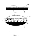
- the device shown in Figure 5 shows a rail pad 1 made from a resilient material comprising a top layer 15 comprising metal particles 16 and a conductive material 17 between the metal particles providing the electrical connection between the metal particles.
Landscapes
- Engineering & Computer Science (AREA)
- Architecture (AREA)
- Civil Engineering (AREA)
- Structural Engineering (AREA)
- Mechanical Engineering (AREA)
- Prevention Of Electric Corrosion (AREA)
Description
- The invention relates to a device and method for inhibiting rail corrosion.
- Rails are made of steel and so are susceptible to corrosion. It is known to inhibit rail corrosion by coating all but the running surface of the rail with a barrier coating or an active coating in order to prevent water or other corrosive substances from coming into contact with the rail. The coatings may be made of an organic material, or of a material which is more anodic than steel, and so corrodes in preference to the steel rail.
- There are a number of problems associated with such barrier or active coatings. Firstly, they are easily damaged. Secondly, they require good preparation of the substrate, particularly the sharp edges of the foot tip, to ensure lasting adhesion of the coating to the steel surface. Thirdly, they are expensive and therefore rails with barrier or active coatings can only be deployed in areas of high corrosion susceptibility such as coastal stretches, tunnels and level crossings. However, rail foot failures, for which corrosion is one of the primary causes, can occur in a very wide range of locations within any railway network.
- It is an object of the present invention to seek to mitigate the above problems.
- Accordingly, the invention provides a device for inhibiting rail corrosion, the device comprising means for galvanically protecting only those parts of the rail which are most susceptible to failure caused by corrosion.
- Using galvanic protection helps overcome the problem of damage on installation as galvanic protection will continue to be effective even in the event of damage. Protecting only those parts of the rail which are most susceptible to failure caused by corrosion ensures that protection is provided where it is most important, whilst reducing costs.
- A conventional rail comprises a head which provides a running surface for the train, a narrower web which extends downwardly from the head and a foot which supports the web.
- The device may comprise means for galvanically protecting the foot of the rail. Stresses are highest at the foot of the rail, and so this is where failure caused by corrosion is most likely.
- The device may comprise a member which, in use, is in contact with the foot of the rail, the galvanic protection means being applied to said member.
- The foot of the rail is supported on a bearer. The bearer may be made of wood, composites, concrete, or steel. A thin, resilient rail pad is positioned between the underside of the foot and the bearer. This rail pad is usually made of a resilient rubber-type material.
- In the preferred embodiment of the invention, the device comprises a rail pad having galvanic protection means. These galvanic protection means are intended to protect the rails that sit above the pad against corrosion.
- Applying the galvanic protection to a rail pad rather than to the rail means that the present invention can be applied to rails already in track. It also means that there is no need to prepare the rail prior to application of the galvanic protection. The only thing which needs to be ensured is that there is electrical contact between the foot of the rail and the pad, meaning that there may be no isolating layers between the foot of the rail and the pad such as thick oxide layers, paint layers etc.
- The whole of the rail pad may have galvanic protection means. The galvanic protection offered by the pad may cover the entire rail.
- Alternatively, only part of the rail pad may have galvanic protection means. The part of the rail foot which is most susceptible to corrosion is the underside of the rail foot. There are a number of factors which are responsible for this.
- The bending of the rail as a consequence of the passage of wheels over the rail introduces tensile stresses in the rail foot the magnitude of which is a function of a number of factors such as the axle load of passing vehicles, the section modulus of the rail, and the spacing between sleepers. However, although these stresses are fully accounted for in the design of the track, they can become critical in the presence of defects or features that act as stress raisers. Two such features are corrosion pits, particularly those that have a sharp point at their base and the very front and back edges of the sleepers in contact with the rail and pad (i.e. in the direction of traffic). The edges in contact with the insulators and the fastening can also act as stress raisers. The weight of the rail and the effect of fastening ensure close electrical contact between the rail and the galvanic coating on the pad.
- Under static conditions, the underside of the rail foot is in contact with the upper surface of the pad. However, the approaching wheel lifts the rail slightly creating a gap between the rail and the pad and thereby enabling the ingress of water, moisture or corrosive fluids from the atmosphere. The pad and rail are in intimate contact when the wheel is on top of the pad. This can squeeze out some of the water, moisture or corrosive fluid, but some will still remain attached to the underside of the rail foot. The passage of the wheel away from the pad again creates a gap between the rail and the pad allowing ingress of water, moisture and corrosive fluid, thereby creating the environment for rail corrosion.
- Another factor that influences corrosion of the underside of the rail foot is the type of pad surface. Some pads have a relatively flat surface in contact with the rail while some others have discrete dimples and hence the areas between the dimples permit accumulation of water, moisture and corrosive fluid.
- The above environments can be conducive to corrosion the magnitude of which is dependent upon the severity of the water, moisture, or corrosive fluid ingress between the pad and rail ranging from complete immersion of the rail underside and pad in water or corrosive fluid to moisture laden air or droplets of water or corrosive fluid. Complete or near complete immersion of the underside of the rail leads to general corrosion of the whole area and hence thinning of the rail foot and eventual fracture. Alternatively, droplets of water or corrosive fluid can lead to the formation of corrosion pits on the underside of the rail foot and, depending on the sharpness of the bottom of the corrosion pit, can lead to fatigue and premature fracture leading to a transverse rail break.
- Accordingly, the entire upper surface of the rail pad may have galvanic protection means. This ensures that the entire underside of the rail foot, which is the part of the rail foot which is most susceptible to corrosion, has galvanic protection. In other words, the whole of the top surface of the pad to a shallow depth may have galvanic protection means and the galvanic protection offered by the pad may therefore cover the whole of the underside of the rail foot. Indeed, because of the "throw power" from anodic protection, the corrosion protection coverage is extended by up to about 15mm beyond the front and back sleeper edges, providing galvanic protection to the edges that are regarded as potential stress raisers. Applying galvanic protection means to the entire upper surface of the rail pad also facilitates application of the galvanic protection means.
- Only part of the upper surface of the rail pad may have galvanic protection means. Thus, the edges of the upper surface of the rail pad may have galvanic protection means. The central area of the upper surface of the rail pad may also have galvanic protection means. This ensures that those parts of the rail seat area which are most susceptible to the effects of corrosion have galvanic protection. However, such selective application may not always be cost effective because of the additional processes required in applying the galvanic protection means.
- The galvanic protection means may comprise a tape, the tape comprising a layer of a metal to act as a sacrificial anode, and a layer of adhesive.
- Zinc, magnesium or aluminium can be used as sacrificial metals for the galvanic protection of steel rails. Galvanic protection of steel rails can also be provided by using alloys of the said metals as sacrificial metals.
- Preferably zinc is used as the metal to act as a sacrificial anode. The tape may be an adhesive tape to facilitate application of the tape to the rail.
- Using a tape as the galvanic protection means allows existing rail pads to be adapted for use in the present invention.
- In an embodiment of the invention an adhesive metal coated tape to provide the galvanic protection is used. However, other methods are also suitable. For example, the galvanic protection means may comprise particles of a metal which acts as a sacrificial anode. Thus, the rail pad may be embedded or impregnated with metal particles, such as zinc particles, or may be sprayed using metal particles, such as zinc particles suspended in a suitable fluid to adhere the particles to the pad. The metal particles, such as zinc particles need to be electrically connected to each other. This electrical connectivity may be achieved by the steel rail to which it is mounted. Alternatively, to ensure a conductive path between individual anodic metal particles, an embodiment of the invention incorporates a conductive material such as carbon or graphite powder within the manufactured coating. The conductive material is preferably inert to the surroundings. Instead of carbon it is also possible to use conductive polymers, conductive rubbers or conductive ceramics. The metal particles may be zinc, aluminium or magnesium particles or alloys thereof.
- Alternatively, the galvanic protection means may comprise a paint of a metal which acts as a sacrificial anode. Thus, the rail pad may be painted using zinc paint. Indeed, it is not even necessary to apply the galvanic protection means to the rail pad. For example, metal tape or metal coated adhesive tape may be applied to the whole underside area of the rail foot in contact with the pad or on part of this area concentrating on the small central area which experiences the highest tensile stresses and that part of the rail which is in contact with the four edges of the pad which can act as potential stress raisers.
- The invention further provides a method of inhibiting rail corrosion, the method comprising the step of galvanically protecting only those parts of the rail which are most susceptible to failure caused by corrosion.
- The method may comprise the step of galvanically protecting the foot of the rail.
- The method may comprise the step of protecting the underside of the foot of the rail.
- The method may comprise the step of protecting part of the underside of the foot of the rail.
- The method may comprise the step of applying galvanic protection means to the foot of the rail.
- Alternatively, the method may comprise the step of applying galvanic protection means to a member which, in use, is in contact with the foot of the rail such as a rail pad.
- The invention will now be illustrated by way of example with reference to the following schematic drawings of which:
-
Figure 1 shows a plan view of a first embodiment of a device according to the invention; -
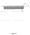
Figure 2 shows a side view of the device shown inFigure 1 ; -
Figure 3 shows a side cross-sectional view of the device shown inFigure 1 , in use, taken along line X - X; and -
Figure 4 shows a plan view of a second embodiment of a device according to the invention. -
Figure 5 shows a side view of an embodiment of the device shown inFigure 1 . - The device shown in
Figures 1 to 3 is arail pad 1. Therail pad 1 is made of a rubber-type or PTFE-type material, and comprises twoside edges 2a, 2b afront edge 2c and aback edge 2d. Therail pad 1 is H-shaped in plan view, twoopposed recesses 3 being formed in the twoside edges 2a,2b. The entire upper surface of therail pad 1 is covered byzinc tape 4. Thezinc tape 4 consists of an upper layer ofzinc 5 and a lower layer of an adhesive 6. - In use, the
rail pad 1 is positioned on abearer 7 such that the two recesses 2 are received in twoupstanding shoulders 8 of thebearer 7. Arail 9 is positioned on top of therail pad 1 and held in place by clips 10. Therail 9 consists of ahead 11 which provides a running surface for the train, anarrower web 12 which extends downwardly from thehead 11 and afoot 13 which supports theweb 12. - As can be seen from
Figure 3 , the zinc tape extends all across the leadingfront edge 2c of thepad 1 and thebearer 7. This ensures that corrosion protection is provided in all locations that are susceptible to ingress of moisture, water or corrosive fluids. Furthermore, the corrosion protection extends to up to about 15 mm away from the front 2c and back 2d edges into thebare rail foot 13. This is achieved as a result of the "throw power" protection provided by anodic zinc tape. Consequently, the stress raising effect of the bearer edge is effectively countered by ensuring that no sharp corrosion pits are formed in this area. - The device shown in
Figure 4 is similar to the device shown inFigure 1 , butzinc tape 4 has been applied only to part of the upper surface of therail pad 1. Thus,zinc tape 4 has been applied to thecentral area 14 and to each of the fouredges rail pad 1, which, in use, are in contact with the two side edges of therail foot 13 and are in line with the front and back edges of thebearer 7, have galvanic protection. - The device shown in
Figure 5 shows arail pad 1 made from a resilient material comprising atop layer 15 comprisingmetal particles 16 and aconductive material 17 between the metal particles providing the electrical connection between the metal particles. - The above embodiments are described by way of example only. A number of possible variations will be apparent to the skilled person without departing from the scope of the claims.
Claims (12)
- A device for inhibiting corrosion of a rail (9), the device comprising means for galvanically protecting the foot (13) of the rail (9) wherein the device comprises a member which, in use, is in contact with the foot of the rail, wherein the member is a rail pad and the galvanic protection means being applied to said member, wherein• the galvanic protection means comprise a tape (4) applied to the rail pad, the tape comprising a layer of a metal (5) and a layer of adhesive (6), or• the galvanic protection means comprise metal particles (16) embedded or impregnated in the rail pad, or• the galvanic protection means comprise metal particles provided to the rail pad by spraying metal particles suspended in a suitable fluid to adhere the particles to the pad, or• the galvanic protection means comprise a rail pad painted with a paint of a metal; and wherein the metal in the tape, the metal particles in the rail pad, the metal particles in the fluid or the metal in the paint acts as a sacrificial anode.
- A device according to claim 1, wherein only part of the rail pad has galvanic protection means.
- A device according to claim 1 or 2, wherein the entire upper surface or only part of the upper surface of the rail pad has galvanic protection means.
- A device according to claim 3, wherein the edges of the upper surface of the rail pad have galvanic protection means.
- A device according to claim 3 or claim 4, wherein the central area of the upper surface of the rail pad has galvanic protection means.
- A device according to any one of claims 1 to 5, wherein the galvanic protection means comprises particles of a metal which acts as a sacrificial anode and a conductive material such as carbon, graphite powder, conductive polymers, conductive rubbers or conductive ceramics to provide electrical conductivity between the particles of the metal acting as a sacrificial anode.
- A device according to any of claims 1 to 6, wherein the layer of metal or the metal in the metal paint is zinc, aluminium, magnesium or alloys of zinc, aluminium or magnesium or wherein the metal particles are zinc, aluminium or magnesium particles or alloys thereof.
- A method of inhibiting rail corrosion, the method comprising the step of galvanically protecting the foot of the rail by applying galvanic protection means to the foot of the rail, by applying galvanic protection means to a member which, in use, is in contact with the foot of the rail, wherein the member is a rail pad and the galvanic protection means being applied to said member, wherein• the galvanic protection means comprise a tape applied to the rail pad, the tape comprising a layer of a metal and a layer of adhesive, or• the galvanic protection means comprise metal particles embedded or impregnated in the rail pad, or• the galvanic protection means comprise metal particles provided to the rail pad by spraying metal particles suspended in a suitable fluid to adhere the particles to the pad, or• the galvanic protection means comprise a rail pad painted with a paint of a metal; and wherein the metal in the tape, the metal particles in the rail pad, the metal particles in the fluid or the metal in the paint acts as a sacrificial anode.
- A method according to claim 8, wherein the layer of metal is zinc, aluminium, magnesium or alloys of zinc, aluminium or magnesium or wherein the metal particles are zinc, aluminium or magnesium particles or alloys thereof.
- A method according to claim 9, wherein a conductive material provides electrical connectivity by providing a conductive path between individual anodic metal particles.
- A method according to claim 10, wherein the conductive material is carbon or graphite powder, conductive polymers, conductive rubbers or conductive ceramics.
- A method according to claim 8 to 11, the method comprising the step of galvanically protecting part of the underside of the foot of the rail.
Priority Applications (1)
| Application Number | Priority Date | Filing Date | Title |
|---|---|---|---|
| PL09718617T PL2265763T3 (en) | 2008-03-13 | 2009-03-13 | A device and method for inhibiting rail corrosion |
Applications Claiming Priority (2)
| Application Number | Priority Date | Filing Date | Title |
|---|---|---|---|
| GBGB0804655.9A GB0804655D0 (en) | 2008-03-13 | 2008-03-13 | A device and method for inhibiting rail corrosion |
| PCT/EP2009/001869 WO2009112285A1 (en) | 2008-03-13 | 2009-03-13 | A device and method for inhibiting rail corrosion |
Publications (2)
| Publication Number | Publication Date |
|---|---|
| EP2265763A1 EP2265763A1 (en) | 2010-12-29 |
| EP2265763B1 true EP2265763B1 (en) | 2015-10-14 |
Family
ID=39328037
Family Applications (1)
| Application Number | Title | Priority Date | Filing Date |
|---|---|---|---|
| EP09718617.5A Not-in-force EP2265763B1 (en) | 2008-03-13 | 2009-03-13 | A device and method for inhibiting rail corrosion |
Country Status (4)
| Country | Link |
|---|---|
| EP (1) | EP2265763B1 (en) |
| GB (1) | GB0804655D0 (en) |
| PL (1) | PL2265763T3 (en) |
| WO (1) | WO2009112285A1 (en) |
Family Cites Families (3)
| Publication number | Priority date | Publication date | Assignee | Title |
|---|---|---|---|---|
| US1785251A (en) * | 1930-02-12 | 1930-12-16 | Etheridge Harry | Support for railway rails |
| DE1028149B (en) * | 1956-03-05 | 1958-04-17 | Deutsche Bundesbahn | Corrosion protection device for the rails of the railway superstructure |
| DE2610263A1 (en) * | 1974-03-13 | 1977-06-02 | Korel Korrosionsschutz Elektro | Anti:corrosion vessel coating - consists of at least two thin layer of different conductivities for heat application and electrode energisation |
-
2008
- 2008-03-13 GB GBGB0804655.9A patent/GB0804655D0/en not_active Ceased
-
2009
- 2009-03-13 WO PCT/EP2009/001869 patent/WO2009112285A1/en not_active Ceased
- 2009-03-13 EP EP09718617.5A patent/EP2265763B1/en not_active Not-in-force
- 2009-03-13 PL PL09718617T patent/PL2265763T3/en unknown
Also Published As
| Publication number | Publication date |
|---|---|
| WO2009112285A1 (en) | 2009-09-17 |
| PL2265763T3 (en) | 2016-04-29 |
| EP2265763A1 (en) | 2010-12-29 |
| GB0804655D0 (en) | 2008-04-16 |
Similar Documents
| Publication | Publication Date | Title |
|---|---|---|
| JPS6031910B2 (en) | Cathode protection device for automobiles | |
| CA2832030C (en) | Integrated ballast mat | |
| WO2009112285A1 (en) | A device and method for inhibiting rail corrosion | |
| US20050078897A1 (en) | Protection of railway axle and bearing against corrosion | |
| MX2013005700A (en) | Method and damping element for reducing the natural vibration of a component. | |
| JP2008231508A (en) | Corrosion resistant steel pipe | |
| JP2006077953A (en) | Fastening member of magnesium alloy member and fastening structure of magnesium alloy member using the fastening member | |
| JP2966829B1 (en) | Piping corrosion protection support structure | |
| US20220242166A1 (en) | Multi-Part Railway Wheel for a Railway Vehicle | |
| EP1400628B1 (en) | Embedded rail | |
| RU210571U1 (en) | ELECTRIC CIRCUIT OF THE ROLLING STOCK DEPARTURE CONTROL DEVICE (UKPSS) | |
| JP2006231327A (en) | Method for temporary protection of blank surfaces against corrosion, and component with temporary corrosion protection | |
| CN202089140U (en) | Anti-erosion crawler board | |
| RU2773713C1 (en) | Device for controlling rolling stock derailment (dcrsd) and method for its installation in working position | |
| JP5834817B2 (en) | Electrodes for anticorrosion | |
| JP5849429B2 (en) | Rust prevention treatment method for laminated rubber bearings | |
| RU209962U1 (en) | RAIL BAR FOR ROLLING STOCK DELETE CONTROL DEVICE (UKPSS) | |
| RU210591U1 (en) | PLATFORM FOR ROLLING STOCK DELETE CONTROL DEVICE | |
| WO2018192949A1 (en) | Fastening system for fastening a rail | |
| RU209897U1 (en) | ELECTRIC CIRCUIT OF THE ROLLING STOCK DEPARTURE CONTROL DEVICE (UKPSS) | |
| JP5849430B2 (en) | Rust prevention treatment method for laminated rubber bearings | |
| JP2002348690A (en) | Toroidal composite galvanic anode | |
| RU209961U1 (en) | JUMPER FOR CONNECTING ROLLING STOCK DELETE CONTROL DEVICE TO CABLE CLUTCH (UCPS) | |
| RU209895U1 (en) | ELECTRICAL CIRCUIT OF THE DEVICE CONTROL DEVICE OF ROLLING STOCK | |
| JPS62263985A (en) | Electrolytic protection method for concrete structure |
Legal Events
| Date | Code | Title | Description |
|---|---|---|---|
| PUAI | Public reference made under article 153(3) epc to a published international application that has entered the european phase |
Free format text: ORIGINAL CODE: 0009012 |
|
| 17P | Request for examination filed |
Effective date: 20101013 |
|
| AK | Designated contracting states |
Kind code of ref document: A1 Designated state(s): AT BE BG CH CY CZ DE DK EE ES FI FR GB GR HR HU IE IS IT LI LT LU LV MC MK MT NL NO PL PT RO SE SI SK TR |
|
| AX | Request for extension of the european patent |
Extension state: AL BA RS |
|
| DAX | Request for extension of the european patent (deleted) | ||
| 17Q | First examination report despatched |
Effective date: 20130218 |
|
| GRAJ | Information related to disapproval of communication of intention to grant by the applicant or resumption of examination proceedings by the epo deleted |
Free format text: ORIGINAL CODE: EPIDOSDIGR1 |
|
| GRAP | Despatch of communication of intention to grant a patent |
Free format text: ORIGINAL CODE: EPIDOSNIGR1 |
|
| INTG | Intention to grant announced |
Effective date: 20150225 |
|
| RAP1 | Party data changed (applicant data changed or rights of an application transferred) |
Owner name: TATA STEEL UK LIMITED |
|
| GRAP | Despatch of communication of intention to grant a patent |
Free format text: ORIGINAL CODE: EPIDOSNIGR1 |
|
| INTG | Intention to grant announced |
Effective date: 20150511 |
|
| GRAS | Grant fee paid |
Free format text: ORIGINAL CODE: EPIDOSNIGR3 |
|
| GRAA | (expected) grant |
Free format text: ORIGINAL CODE: 0009210 |
|
| AK | Designated contracting states |
Kind code of ref document: B1 Designated state(s): AT BE BG CH CY CZ DE DK EE ES FI FR GB GR HR HU IE IS IT LI LT LU LV MC MK MT NL NO PL PT RO SE SI SK TR |
|
| REG | Reference to a national code |
Ref country code: GB Ref legal event code: FG4D |
|
| RIN1 | Information on inventor provided before grant (corrected) |
Inventor name: GRAHAM, KEVIN VICTOR Inventor name: JAISWAL, SHREEKANT |
|
| REG | Reference to a national code |
Ref country code: AT Ref legal event code: REF Ref document number: 755172 Country of ref document: AT Kind code of ref document: T Effective date: 20151015 Ref country code: CH Ref legal event code: EP |
|
| RIN2 | Information on inventor provided after grant (corrected) |
Inventor name: GRAHAM, KEVIN VICTOR Inventor name: JAISWAL, SHREEKANT |
|
| REG | Reference to a national code |
Ref country code: IE Ref legal event code: FG4D |
|
| REG | Reference to a national code |
Ref country code: DE Ref legal event code: R096 Ref document number: 602009034213 Country of ref document: DE |
|
| REG | Reference to a national code |
Ref country code: CH Ref legal event code: NV Representative=s name: MICHELI AND CIE SA, CH |
|
| REG | Reference to a national code |
Ref country code: NL Ref legal event code: MP Effective date: 20151014 |
|
| REG | Reference to a national code |
Ref country code: LT Ref legal event code: MG4D |
|
| REG | Reference to a national code |
Ref country code: AT Ref legal event code: MK05 Ref document number: 755172 Country of ref document: AT Kind code of ref document: T Effective date: 20151014 |
|
| REG | Reference to a national code |
Ref country code: FR Ref legal event code: PLFP Year of fee payment: 8 |
|
| PG25 | Lapsed in a contracting state [announced via postgrant information from national office to epo] |
Ref country code: NL Free format text: LAPSE BECAUSE OF FAILURE TO SUBMIT A TRANSLATION OF THE DESCRIPTION OR TO PAY THE FEE WITHIN THE PRESCRIBED TIME-LIMIT Effective date: 20151014 Ref country code: IS Free format text: LAPSE BECAUSE OF FAILURE TO SUBMIT A TRANSLATION OF THE DESCRIPTION OR TO PAY THE FEE WITHIN THE PRESCRIBED TIME-LIMIT Effective date: 20160214 Ref country code: IT Free format text: LAPSE BECAUSE OF FAILURE TO SUBMIT A TRANSLATION OF THE DESCRIPTION OR TO PAY THE FEE WITHIN THE PRESCRIBED TIME-LIMIT Effective date: 20151014 Ref country code: NO Free format text: LAPSE BECAUSE OF FAILURE TO SUBMIT A TRANSLATION OF THE DESCRIPTION OR TO PAY THE FEE WITHIN THE PRESCRIBED TIME-LIMIT Effective date: 20160114 Ref country code: ES Free format text: LAPSE BECAUSE OF FAILURE TO SUBMIT A TRANSLATION OF THE DESCRIPTION OR TO PAY THE FEE WITHIN THE PRESCRIBED TIME-LIMIT Effective date: 20151014 Ref country code: LT Free format text: LAPSE BECAUSE OF FAILURE TO SUBMIT A TRANSLATION OF THE DESCRIPTION OR TO PAY THE FEE WITHIN THE PRESCRIBED TIME-LIMIT Effective date: 20151014 Ref country code: HR Free format text: LAPSE BECAUSE OF FAILURE TO SUBMIT A TRANSLATION OF THE DESCRIPTION OR TO PAY THE FEE WITHIN THE PRESCRIBED TIME-LIMIT Effective date: 20151014 |
|
| PGFP | Annual fee paid to national office [announced via postgrant information from national office to epo] |
Ref country code: CH Payment date: 20160328 Year of fee payment: 8 |
|
| PG25 | Lapsed in a contracting state [announced via postgrant information from national office to epo] |
Ref country code: PT Free format text: LAPSE BECAUSE OF FAILURE TO SUBMIT A TRANSLATION OF THE DESCRIPTION OR TO PAY THE FEE WITHIN THE PRESCRIBED TIME-LIMIT Effective date: 20160215 Ref country code: AT Free format text: LAPSE BECAUSE OF FAILURE TO SUBMIT A TRANSLATION OF THE DESCRIPTION OR TO PAY THE FEE WITHIN THE PRESCRIBED TIME-LIMIT Effective date: 20151014 Ref country code: SE Free format text: LAPSE BECAUSE OF FAILURE TO SUBMIT A TRANSLATION OF THE DESCRIPTION OR TO PAY THE FEE WITHIN THE PRESCRIBED TIME-LIMIT Effective date: 20151014 Ref country code: LV Free format text: LAPSE BECAUSE OF FAILURE TO SUBMIT A TRANSLATION OF THE DESCRIPTION OR TO PAY THE FEE WITHIN THE PRESCRIBED TIME-LIMIT Effective date: 20151014 Ref country code: FI Free format text: LAPSE BECAUSE OF FAILURE TO SUBMIT A TRANSLATION OF THE DESCRIPTION OR TO PAY THE FEE WITHIN THE PRESCRIBED TIME-LIMIT Effective date: 20151014 Ref country code: GR Free format text: LAPSE BECAUSE OF FAILURE TO SUBMIT A TRANSLATION OF THE DESCRIPTION OR TO PAY THE FEE WITHIN THE PRESCRIBED TIME-LIMIT Effective date: 20160115 |
|
| PGFP | Annual fee paid to national office [announced via postgrant information from national office to epo] |
Ref country code: PL Payment date: 20160314 Year of fee payment: 8 |
|
| REG | Reference to a national code |
Ref country code: DE Ref legal event code: R097 Ref document number: 602009034213 Country of ref document: DE |
|
| PG25 | Lapsed in a contracting state [announced via postgrant information from national office to epo] |
Ref country code: CZ Free format text: LAPSE BECAUSE OF FAILURE TO SUBMIT A TRANSLATION OF THE DESCRIPTION OR TO PAY THE FEE WITHIN THE PRESCRIBED TIME-LIMIT Effective date: 20151014 |
|
| PLBE | No opposition filed within time limit |
Free format text: ORIGINAL CODE: 0009261 |
|
| STAA | Information on the status of an ep patent application or granted ep patent |
Free format text: STATUS: NO OPPOSITION FILED WITHIN TIME LIMIT |
|
| PG25 | Lapsed in a contracting state [announced via postgrant information from national office to epo] |
Ref country code: SK Free format text: LAPSE BECAUSE OF FAILURE TO SUBMIT A TRANSLATION OF THE DESCRIPTION OR TO PAY THE FEE WITHIN THE PRESCRIBED TIME-LIMIT Effective date: 20151014 Ref country code: EE Free format text: LAPSE BECAUSE OF FAILURE TO SUBMIT A TRANSLATION OF THE DESCRIPTION OR TO PAY THE FEE WITHIN THE PRESCRIBED TIME-LIMIT Effective date: 20151014 Ref country code: RO Free format text: LAPSE BECAUSE OF FAILURE TO SUBMIT A TRANSLATION OF THE DESCRIPTION OR TO PAY THE FEE WITHIN THE PRESCRIBED TIME-LIMIT Effective date: 20151014 Ref country code: DK Free format text: LAPSE BECAUSE OF FAILURE TO SUBMIT A TRANSLATION OF THE DESCRIPTION OR TO PAY THE FEE WITHIN THE PRESCRIBED TIME-LIMIT Effective date: 20151014 Ref country code: BE Free format text: LAPSE BECAUSE OF NON-PAYMENT OF DUE FEES Effective date: 20160331 |
|
| 26N | No opposition filed |
Effective date: 20160715 |
|
| PG25 | Lapsed in a contracting state [announced via postgrant information from national office to epo] |
Ref country code: LU Free format text: LAPSE BECAUSE OF FAILURE TO SUBMIT A TRANSLATION OF THE DESCRIPTION OR TO PAY THE FEE WITHIN THE PRESCRIBED TIME-LIMIT Effective date: 20160313 Ref country code: MC Free format text: LAPSE BECAUSE OF FAILURE TO SUBMIT A TRANSLATION OF THE DESCRIPTION OR TO PAY THE FEE WITHIN THE PRESCRIBED TIME-LIMIT Effective date: 20151014 |
|
| PG25 | Lapsed in a contracting state [announced via postgrant information from national office to epo] |
Ref country code: SI Free format text: LAPSE BECAUSE OF FAILURE TO SUBMIT A TRANSLATION OF THE DESCRIPTION OR TO PAY THE FEE WITHIN THE PRESCRIBED TIME-LIMIT Effective date: 20151014 |
|
| REG | Reference to a national code |
Ref country code: GB Ref legal event code: 732E Free format text: REGISTERED BETWEEN 20161110 AND 20161116 |
|
| REG | Reference to a national code |
Ref country code: IE Ref legal event code: MM4A |
|
| REG | Reference to a national code |
Ref country code: DE Ref legal event code: R081 Ref document number: 602009034213 Country of ref document: DE Owner name: BRITISH STEEL LIMITED, SCUNTHORPE, GB Free format text: FORMER OWNER: TATA STEEL UK LIMITED, LONDON, GB |
|
| PG25 | Lapsed in a contracting state [announced via postgrant information from national office to epo] |
Ref country code: BE Free format text: LAPSE BECAUSE OF FAILURE TO SUBMIT A TRANSLATION OF THE DESCRIPTION OR TO PAY THE FEE WITHIN THE PRESCRIBED TIME-LIMIT Effective date: 20151014 |
|
| PG25 | Lapsed in a contracting state [announced via postgrant information from national office to epo] |
Ref country code: IE Free format text: LAPSE BECAUSE OF NON-PAYMENT OF DUE FEES Effective date: 20160313 |
|
| REG | Reference to a national code |
Ref country code: CH Ref legal event code: PFA Owner name: BRITISH STEEL LIMITED, GB Free format text: FORMER OWNER: LONGS STEEL UK LIMITED, GB Ref country code: CH Ref legal event code: PUE Owner name: LONGS STEEL UK LIMITED, GB Free format text: FORMER OWNER: TATA STEEL UK LIMITED, GB |
|
| REG | Reference to a national code |
Ref country code: FR Ref legal event code: PLFP Year of fee payment: 9 |
|
| PGFP | Annual fee paid to national office [announced via postgrant information from national office to epo] |
Ref country code: DE Payment date: 20170322 Year of fee payment: 9 Ref country code: FR Payment date: 20170322 Year of fee payment: 9 |
|
| PGFP | Annual fee paid to national office [announced via postgrant information from national office to epo] |
Ref country code: GB Payment date: 20170223 Year of fee payment: 9 |
|
| REG | Reference to a national code |
Ref country code: FR Ref legal event code: TP Owner name: BRITISH STEEL LIMITED, GB Effective date: 20170626 |
|
| REG | Reference to a national code |
Ref country code: FR Ref legal event code: CD Owner name: BRITISH STEEL LIMITED, GB Effective date: 20170705 Ref country code: FR Ref legal event code: CJ Effective date: 20170705 |
|
| PG25 | Lapsed in a contracting state [announced via postgrant information from national office to epo] |
Ref country code: MT Free format text: LAPSE BECAUSE OF FAILURE TO SUBMIT A TRANSLATION OF THE DESCRIPTION OR TO PAY THE FEE WITHIN THE PRESCRIBED TIME-LIMIT Effective date: 20151014 |
|
| REG | Reference to a national code |
Ref country code: CH Ref legal event code: PL |
|
| REG | Reference to a national code |
Ref country code: FR Ref legal event code: CA Effective date: 20170705 |
|
| PG25 | Lapsed in a contracting state [announced via postgrant information from national office to epo] |
Ref country code: CH Free format text: LAPSE BECAUSE OF NON-PAYMENT OF DUE FEES Effective date: 20170331 Ref country code: LI Free format text: LAPSE BECAUSE OF NON-PAYMENT OF DUE FEES Effective date: 20170331 |
|
| PG25 | Lapsed in a contracting state [announced via postgrant information from national office to epo] |
Ref country code: HU Free format text: LAPSE BECAUSE OF FAILURE TO SUBMIT A TRANSLATION OF THE DESCRIPTION OR TO PAY THE FEE WITHIN THE PRESCRIBED TIME-LIMIT; INVALID AB INITIO Effective date: 20090313 Ref country code: CY Free format text: LAPSE BECAUSE OF FAILURE TO SUBMIT A TRANSLATION OF THE DESCRIPTION OR TO PAY THE FEE WITHIN THE PRESCRIBED TIME-LIMIT Effective date: 20151014 |
|
| PG25 | Lapsed in a contracting state [announced via postgrant information from national office to epo] |
Ref country code: MK Free format text: LAPSE BECAUSE OF FAILURE TO SUBMIT A TRANSLATION OF THE DESCRIPTION OR TO PAY THE FEE WITHIN THE PRESCRIBED TIME-LIMIT Effective date: 20151014 Ref country code: TR Free format text: LAPSE BECAUSE OF FAILURE TO SUBMIT A TRANSLATION OF THE DESCRIPTION OR TO PAY THE FEE WITHIN THE PRESCRIBED TIME-LIMIT Effective date: 20151014 Ref country code: MT Free format text: LAPSE BECAUSE OF FAILURE TO SUBMIT A TRANSLATION OF THE DESCRIPTION OR TO PAY THE FEE WITHIN THE PRESCRIBED TIME-LIMIT Effective date: 20160331 |
|
| PG25 | Lapsed in a contracting state [announced via postgrant information from national office to epo] |
Ref country code: BG Free format text: LAPSE BECAUSE OF FAILURE TO SUBMIT A TRANSLATION OF THE DESCRIPTION OR TO PAY THE FEE WITHIN THE PRESCRIBED TIME-LIMIT Effective date: 20151014 |
|
| REG | Reference to a national code |
Ref country code: DE Ref legal event code: R119 Ref document number: 602009034213 Country of ref document: DE |
|
| GBPC | Gb: european patent ceased through non-payment of renewal fee |
Effective date: 20180313 |
|
| PG25 | Lapsed in a contracting state [announced via postgrant information from national office to epo] |
Ref country code: DE Free format text: LAPSE BECAUSE OF NON-PAYMENT OF DUE FEES Effective date: 20181002 |
|
| PG25 | Lapsed in a contracting state [announced via postgrant information from national office to epo] |
Ref country code: GB Free format text: LAPSE BECAUSE OF NON-PAYMENT OF DUE FEES Effective date: 20180313 |
|
| PG25 | Lapsed in a contracting state [announced via postgrant information from national office to epo] |
Ref country code: FR Free format text: LAPSE BECAUSE OF NON-PAYMENT OF DUE FEES Effective date: 20180331 |
|
| PG25 | Lapsed in a contracting state [announced via postgrant information from national office to epo] |
Ref country code: PL Free format text: LAPSE BECAUSE OF NON-PAYMENT OF DUE FEES Effective date: 20170313 |