EP2265156B1 - Apparatus and capsule for making a drink - Google Patents
Apparatus and capsule for making a drink Download PDFInfo
- Publication number
- EP2265156B1 EP2265156B1 EP09718825.4A EP09718825A EP2265156B1 EP 2265156 B1 EP2265156 B1 EP 2265156B1 EP 09718825 A EP09718825 A EP 09718825A EP 2265156 B1 EP2265156 B1 EP 2265156B1
- Authority
- EP
- European Patent Office
- Prior art keywords
- container
- capsule
- appliance
- holder
- injection head
- Prior art date
- Legal status (The legal status is an assumption and is not a legal conclusion. Google has not performed a legal analysis and makes no representation as to the accuracy of the status listed.)
- Active
Links
- 239000002775 capsule Substances 0.000 title claims description 147
- 238000000605 extraction Methods 0.000 claims description 68
- 238000002347 injection Methods 0.000 claims description 66
- 239000007924 injection Substances 0.000 claims description 66
- 230000007246 mechanism Effects 0.000 claims description 23
- XLYOFNOQVPJJNP-UHFFFAOYSA-N water Substances O XLYOFNOQVPJJNP-UHFFFAOYSA-N 0.000 claims description 14
- 238000003780 insertion Methods 0.000 claims description 11
- 230000037431 insertion Effects 0.000 claims description 11
- 235000013361 beverage Nutrition 0.000 claims description 9
- 230000005484 gravity Effects 0.000 claims description 8
- 239000000126 substance Substances 0.000 claims description 7
- 238000013459 approach Methods 0.000 claims description 2
- 235000021056 liquid food Nutrition 0.000 claims 1
- 238000002360 preparation method Methods 0.000 description 12
- 238000006073 displacement reaction Methods 0.000 description 5
- 230000000295 complement effect Effects 0.000 description 3
- 238000007599 discharging Methods 0.000 description 2
- 239000000463 material Substances 0.000 description 2
- 230000001133 acceleration Effects 0.000 description 1
- 235000009508 confectionery Nutrition 0.000 description 1
- 238000010276 construction Methods 0.000 description 1
- 235000013305 food Nutrition 0.000 description 1
- 239000012263 liquid product Substances 0.000 description 1
- 230000000284 resting effect Effects 0.000 description 1
- 238000007789 sealing Methods 0.000 description 1
Images


Classifications
-
- A—HUMAN NECESSITIES
- A47—FURNITURE; DOMESTIC ARTICLES OR APPLIANCES; COFFEE MILLS; SPICE MILLS; SUCTION CLEANERS IN GENERAL
- A47J—KITCHEN EQUIPMENT; COFFEE MILLS; SPICE MILLS; APPARATUS FOR MAKING BEVERAGES
- A47J31/00—Apparatus for making beverages
- A47J31/24—Coffee-making apparatus in which hot water is passed through the filter under pressure, i.e. in which the coffee grounds are extracted under pressure
- A47J31/34—Coffee-making apparatus in which hot water is passed through the filter under pressure, i.e. in which the coffee grounds are extracted under pressure with hot water under liquid pressure
- A47J31/36—Coffee-making apparatus in which hot water is passed through the filter under pressure, i.e. in which the coffee grounds are extracted under pressure with hot water under liquid pressure with mechanical pressure-producing means
- A47J31/3604—Coffee-making apparatus in which hot water is passed through the filter under pressure, i.e. in which the coffee grounds are extracted under pressure with hot water under liquid pressure with mechanical pressure-producing means with a mechanism arranged to move the brewing chamber between loading, infusing and ejecting stations
- A47J31/3623—Cartridges being employed
- A47J31/3642—Cartridge magazines therefor
-
- A—HUMAN NECESSITIES
- A47—FURNITURE; DOMESTIC ARTICLES OR APPLIANCES; COFFEE MILLS; SPICE MILLS; SUCTION CLEANERS IN GENERAL
- A47J—KITCHEN EQUIPMENT; COFFEE MILLS; SPICE MILLS; APPARATUS FOR MAKING BEVERAGES
- A47J31/00—Apparatus for making beverages
- A47J31/24—Coffee-making apparatus in which hot water is passed through the filter under pressure, i.e. in which the coffee grounds are extracted under pressure
- A47J31/34—Coffee-making apparatus in which hot water is passed through the filter under pressure, i.e. in which the coffee grounds are extracted under pressure with hot water under liquid pressure
- A47J31/36—Coffee-making apparatus in which hot water is passed through the filter under pressure, i.e. in which the coffee grounds are extracted under pressure with hot water under liquid pressure with mechanical pressure-producing means
- A47J31/3604—Coffee-making apparatus in which hot water is passed through the filter under pressure, i.e. in which the coffee grounds are extracted under pressure with hot water under liquid pressure with mechanical pressure-producing means with a mechanism arranged to move the brewing chamber between loading, infusing and ejecting stations
- A47J31/3623—Cartridges being employed
- A47J31/3628—Perforating means therefor
-
- A—HUMAN NECESSITIES
- A47—FURNITURE; DOMESTIC ARTICLES OR APPLIANCES; COFFEE MILLS; SPICE MILLS; SUCTION CLEANERS IN GENERAL
- A47J—KITCHEN EQUIPMENT; COFFEE MILLS; SPICE MILLS; APPARATUS FOR MAKING BEVERAGES
- A47J31/00—Apparatus for making beverages
- A47J31/24—Coffee-making apparatus in which hot water is passed through the filter under pressure, i.e. in which the coffee grounds are extracted under pressure
- A47J31/34—Coffee-making apparatus in which hot water is passed through the filter under pressure, i.e. in which the coffee grounds are extracted under pressure with hot water under liquid pressure
- A47J31/36—Coffee-making apparatus in which hot water is passed through the filter under pressure, i.e. in which the coffee grounds are extracted under pressure with hot water under liquid pressure with mechanical pressure-producing means
- A47J31/3604—Coffee-making apparatus in which hot water is passed through the filter under pressure, i.e. in which the coffee grounds are extracted under pressure with hot water under liquid pressure with mechanical pressure-producing means with a mechanism arranged to move the brewing chamber between loading, infusing and ejecting stations
- A47J31/3623—Cartridges being employed
- A47J31/3633—Means to perform transfer from a loading position to an infusing position
-
- A—HUMAN NECESSITIES
- A47—FURNITURE; DOMESTIC ARTICLES OR APPLIANCES; COFFEE MILLS; SPICE MILLS; SUCTION CLEANERS IN GENERAL
- A47J—KITCHEN EQUIPMENT; COFFEE MILLS; SPICE MILLS; APPARATUS FOR MAKING BEVERAGES
- A47J31/00—Apparatus for making beverages
- A47J31/24—Coffee-making apparatus in which hot water is passed through the filter under pressure, i.e. in which the coffee grounds are extracted under pressure
- A47J31/34—Coffee-making apparatus in which hot water is passed through the filter under pressure, i.e. in which the coffee grounds are extracted under pressure with hot water under liquid pressure
- A47J31/36—Coffee-making apparatus in which hot water is passed through the filter under pressure, i.e. in which the coffee grounds are extracted under pressure with hot water under liquid pressure with mechanical pressure-producing means
- A47J31/3604—Coffee-making apparatus in which hot water is passed through the filter under pressure, i.e. in which the coffee grounds are extracted under pressure with hot water under liquid pressure with mechanical pressure-producing means with a mechanism arranged to move the brewing chamber between loading, infusing and ejecting stations
- A47J31/3623—Cartridges being employed
- A47J31/3638—Means to eject the cartridge after brewing
Definitions
- the present invention relates to an apparatus and a capsule for the preparation of a beverage by injection of hot water under pressure into the capsule.
- Apparatus for the preparation of drinks by the injection of hot water through a capsule containing a substance to be extracted, such as coffee are known and described for example in the publications EP1646304 , EP1646305 , WO2007016977 .
- the capsule is introduced into the device by orienting the capsule so that the injection and extraction faces are in a substantially vertical plane.
- the capsule is held in an intermediate position and then moved from the intermediate position to its final position in the capsule-holder when the closure mechanism for the injection is activated.
- the capsule is introduced directly into a capsule-holder in a first position, the capsule-holder then being pivoted in a second injection position and after the injection pivoted again in a third position for the ejection of the capsule.
- a disadvantage of this prior system results from multiple movements of the capsule holder, the complexity of the mechanical parts can reduce the reliability of the device and increase its cost. Moreover, it is more difficult to ensure perfect sealing of the injection head against the capsule-holder, around the capsule, taking into account the high pressures (6 to 12 bar).
- the object of the invention is to provide an apparatus for the preparation of drinks from capsules by injection of hot water under pressure, which is reliable and economical.
- Objects of the invention are realized by the apparatus for the preparation of drinks from capsules by injection of hot water under pressure according to claim 1.
- the side wall of the capsule shell has a truncated flared shape, the taper angle in one embodiment being between 0 ° and 10 °.
- the capsule filled with a substance for the preparation of a drink has a weight distribution such that the center of gravity G is located in the lower part of the capsule, namely between the line to half-height and the bottom. This improves the orientation of the capsule when it falls into the housing to ensure that it falls reliably.
- the center of gravity can be lowered by varying the thickness and shape of the capsule shell, by example by having an addition of material on the bottom wall of the capsule.
- the bottom of the capsule may be thicker than the side walls of the capsule.
- the center of gravity is lowered by filling only partially the shell of the capsule with a substance for the preparation of a beverage at a level below 95%, preferably below 90% of the total volume of the inside of the capsule.
- the angle of the introduction channel allows the introduction of the capsule to its final position in the capsule-holder and also allows the easy ejection of the capsule in a compact and economical configuration.
- the introduction channel is preferably inclined at an angle between 40 and 60 degrees with respect to the horizontal plane. The angle of the introduction channel conjugated with the inclination of the side wall portion of the capsule housing and the shape of the capsule ensures that the capsule is stopped without additional mechanism.
- the extraction block comprises an ejection orifice of the capsule which can advantageously be oriented at a lateral angle ⁇ between 20 and 60 degrees, with respect to a vertical plane (PV) crossing an axis (IN) of the introduction channel.
- the lateral angle ⁇ is between 30 and 50 degrees.
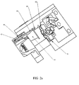
- an apparatus for making a drink from a capsule comprises an extraction block 4 with a body 6, a capsule holder 8, an injection head 10 and an opening mechanism 12 of the extraction chamber.
- the extraction block further comprises an insertion channel 14 for insertion of a capsule into the apparatus, and an ejection channel or port 16 for discharging a capsule after use.
- the capsule holder 8 comprises a housing 18 with a side wall 20 and an extraction wall 22 forming the bottom of the housing 18.
- the side wall 20 of the housing has a truncated flared shape corresponding to the shape of the capsule 3 intended to be received in the dwelling.
- the extraction wall may have one or more perforation tips and one or more orifices for the flow of the liquid product extracted from the capsule after perforation.
- the extraction wall and the housing of the capsule-holder, as well as the capsule can advantageously be made as described in the patent EP 507905 or EP1646304 or may have other configurations.
- the side wall of the capsule shell has a truncated flared shape, the taper angle in one embodiment being between 0 ° and 10 °.
- the bottom wall of the capsule may be of substantially convex, concave or flat shape.
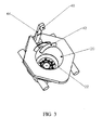
- the capsule holder according to the invention further comprises an ejection mechanism of the capsule 24 which will be described in more detail below.
- the injection head 10 comprises an injection wall 26 with perforation tips 28 and a pressurized water supply channel 30 for the injection of water through the upper wall 32 of the capsule when the head injection valve is closed against the capsule-holder 8, as illustrated in FIG. figure 2d .
- the injection wall may advantageously have the construction as described in the patent EP1646304 or may have other configurations.
- the injection head is removable between an open position allowing the introduction of a capsule into the housing 18 of the capsule-holder 8, as illustrated in FIG. figure 2a , and a closed position where the injection head is pressed against the capsule-holder as shown in FIG. figure 2d .
- a seal 32 surrounding the wall Injection is used to hermetically seal the injection head against the flange 34 of the capsule which is pressed on the other side against the rim 35 of the capsule-holder.
- the displacement of the injection head is actuated by the opening and closing mechanism 12, this mechanism comprising at least two arms or pairs of articulated arms 36a, 36b.
- One arm or pair of arms 36a is pivotally attached 38a to the body 6 of the extraction block and another arm or pair of arms 36b is pivotally attached 38b to the injection head, both arms (or two pairs of arms) being articulated relative to each other about an articulation axis 38c.
- the axis of rotation 38a of the first articulated arm 36a is integral with a lever 40 which, in the illustrated embodiment, is intended to be controlled manually by a user for the rotation of the first articulated arm 36a.
- the first arm (or pairs of arms) hinged 36a is shorter than the second arm (or pairs of arms) articulated 36b to reduce the size of the extraction block, including the volume necessary for the movements of the articulated arms.
- the torque necessary for the displacement of the injection head in the high position is low.
- the bearing force must be big.
- the articulated arms allow a large displacement at low torque at the beginning of the closing movement and a small displacement at high force for closing. Locking in the closed position is ensured when the articulated arms 36a, 36b are aligned or slightly past the alignment point, as illustrated in FIG. figure 2d .
- the mechanism for ejecting the capsule 24 comprises an ejector pusher 42 coupled to a tie rod 44, and a return spring 46.
- the return spring maintains the pusher 42 in a recessed position (low position) as illustrated in FIG. figure 2a .
- the tie rod 44 comprises a hook 48 intended to engage a complementary hook or shoulder 50 on the injection head 10 when the latter is raised towards its upper position as illustrated in FIG. figure 2e .
- the pusher 42 is raised out of its retracted position and raises the flange 52 of the capsule to eject it from the housing 18 and have it evacuated by the
- the hook 48 of the tie rod is released from the shoulder or the complementary hook 50 of the injection head by a cam 54, integral or fixed to the body 6, when the injection head reaches or is close to its high (ie the most open) position as illustrated in the figure 2f .
- the tie rod is thus released and pushed back by the spring 46 into its retracted position, as illustrated in FIG. figure 2a , ready for the introduction of a new capsule in the housing of the capsule-holder.
- the pusher is pushed by a return spring 46.
- the pulling portion comprises a loop whose free end 48 'acts as a hook to engage the shoulder 50 of the injection head, the loop having a certain elasticity allowing it to be unhooked from the injection head when it reaches its upper (open) position.
- the injection head is in its upper position as illustrated in FIG. figure 2a , and the user inserts a capsule into the insertion channel 14.
- the IN axis of the introduction channel has an angle of inclination ( ⁇ ) between 30 and 70 degrees, preferably between 40 and 60 degrees, for example about 45 degrees, relative to a horizontal plane HZ.
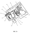
- the capsule 3 slides by force of gravity along the introduction channel until it falls into the housing 18 of the capsule-holder 8 as illustrated in FIG. figure 2b .
- the combination of channel tilt angle ( ⁇ ), weight, capsule shape, and coefficient of friction of the capsule against the channel is configured to provide a top speed. (V) of the capsule at the moment just before abutting against the side wall, between 0.5 ms -1 and 3.0 ms -1 , preferably between 1.0 ms -1 and 2.0 ms -1 .
- the kinetic energy of the capsule is, by this measure, optimized to ensure that the capsule falls into the housing 18 reliably and in the correct position.
- the capsule filled with a substance for the preparation of a beverage has a weight distribution such that the center of gravity G is in the lower part of the capsule, namely between the mid-line height M and the bottom. This improves the orientation of the capsule when it falls into the housing 18 to ensure that it falls reliably.
- the center of gravity can be lowered by varying the thickness and shape of the envelope of the capsule, for example by having an addition of material on the bottom wall of the capsule.
- the bottom of the capsule may be thicker than the side walls of the capsule.
- the center of gravity can also be lowered by filling only partially the capsule shell with a substance for the preparation of a beverage, at a level of less than 95%, preferably less than 90% of the total volume of the capsule. inside the capsule.
- the opening and closing mechanism 12 is then actuated by the rotation of the lever 40 which rotates the first articulated arm 36a, which in turn rotates the second articulated arm 36b, lowering the injection head 10 until it comes to bear against the capsule in the housing 18 as illustrated in the figure 2d .
- the seal 32 of the injection head rests hermetically on the upper face of the collar 34 of the capsule sandwiched against the rim of the capsule-holder, and the tips 28 of the head of the injection pierce the upper wall of the capsule.
- the water under pressure between 5 and 12 bar is injected through the feed channel 30 and enters the capsule through the orifices pierced by the points 28.
- the water pressure inside the capsule reaches a certain level , the bottom of the capsule descends against the perforation points of the extraction wall 22 and the substance to be extracted flows through the orifices of the extraction wall.
- the injection head After the end of water injection, the injection head is raised by actuating the lever 40. During the ascent, the injection head engages the hook 48 of the ejection mechanism which, being raised, rises the push member 42 which presses on the flange 34 of the capsule and ejects the housing 18.
- the pusher 42 guided by bearings 56 or slides preferably performs a curvilinear movement or rectilinear but inclined towards the discharge port 16 for better project the capsule 3 in the direction of the discharge port.
- the rotation of the articulated arms 36a, 36b can be performed manually as for the illustrated embodiment, but it can also be performed by a motor.
- the opening and closing mechanism of the injection head can also be constructed otherwise, for example in the form of a linear actuator with a screw-nut system, or by a hydraulic system.
- the axis IN of the insertion channel 14 of the capsule is not aligned on the same axis EV as the discharge port 16 of the capsule. This makes it possible to form a stop that stops the capsule and causes it to fall into the housing 18 of the capsule-holder towards the end of the descent into the insertion channel 14.
- the discharge orifice is directed at an angle ⁇ preferably between 30 and 50 degrees, for example about 45 degrees of a vertical plane PV passing through the axis IN of the introduction channel (see Figure 1 (c) . This configuration also allows the capsules to be emptied into a collection basket of used capsules next to the extraction block.
- the introduction of the capsule in its housing does not require any particular or complicated mechanism, and the ejection of the capsule from its housing is performed automatically and simply by raising the injection head.
- a simple, reliable and ergonomic system for introducing and ejecting the capsules is therefore achieved by the present invention.
- the mechanism for discharging the capsule 24 ' comprises a discharge rail 60 and a locking device 62 of the capsule holder 8'.
- the capsule holder 8 ' is pivotally mounted about an axis of rotation 64 relative to the body 6 of the extraction block.
- the evacuation rail 60 is integral with the body 6 of the extraction block and preferably comprises two rail portions 60a, 60b, as illustrated in FIG. Figure 6c disposed on either side of the cavity 18 of the capsule-holder.
- the rail portions 60a, 60b are separated by a distance w slightly greater than the diameter d of the part of the capsule below the flange 34.
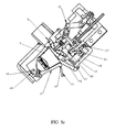
- the capsule holder comprises a rim 35 'with recessed portions 35a, 35b under the discharge rails when the capsule-holder is in the high position (position of introduction of the capsule and extraction as illustrated in the figures 5a , 5b ).
- the portion of the rim 35 'of the capsule holder which is not disposed under the guide rail is at the height of the upper surface of the discharge rail in the extraction position, so that the collar of the capsule can rest against an almost continuous rim around the housing 18.
- the capsule Due to the acceleration of the capsule-holder during its pivoting and the rapid movement, the capsule is ejected out of the housing of the capsule-holder with a certain speed making it possible to disengage itself well from the extraction block and to be propelled into an evacuation tank 59 (see Fig. 6b ) capsules disposed under the extraction block.
- the rotation of the cartridge-holder from its extraction position to the evacuation position is effected by a spring 65, in the example illustrated a toroidal spring, but many other forms of spring and mechanisms of rotation of the capsule may be considered in the context of this invention.
- the rotation of the capsule can also be driven by a motor or electric actuator.
- the return of the capsule holder from its evacuation position to the extraction position is ensured by a return arm 66 (see FIG. Figure 6c ) which is pivotally attached to the injection head 10.
- the return arm 66 is pivotally mounted about an axis 68 attached to a portion integral with the injection head 10, and towards the other end arm there is a slot 70 in which a finger 71 integral with the body of the capsule holder 8 'is inserted.
- the slot 70 allows a certain displacement of the finger 71 relative to the return arm 66 when the injection head moves between the lower extraction position (as illustrated in FIG. figure 5c ) at an intermediate position between the extraction position and the high position.
- the return arm 66 engages the finger 71 of the capsule-holder and turns it to its high position (extraction position). In this high position illustrated in the figures 5a and 6a .
- the locking device 62 of the capsule-holder comprises a removable body 74 with a locking finger 75 resting against a shoulder 76 of the capsule-holder when it is in its extraction position and the removable body is in its locking position, as illustrated in figure 5a .
- the removable body is slidably mounted on the body 6 of the extraction block, a spring 77 disposed between the extraction block and the removable body pushing the removable body into the locking position illustrated in FIG. figure 5a .
- a hook 78 is mounted on an axis 79 pivotally relative to the removable body 74, and has a protrusion 80 for engaging a complementary shoulder 81 of the injection head (see figure 5c ) when it goes down to the extraction position.
- the hook 78 which engages the ejection head removes the removable body 74, against the thrust of the spring 77 so that the locking finger 75 is disengaged from the shoulder 76 of the capsule-holder, as illustrated in FIGS. figures 5d and 5th .
- This allows the capsule holder to pivot to the discharge position by the force of the spring 64 (shown in FIG. Figure 6c ) acting on the capsule-holder.
- the hook 78 abuts against a cam 82 fixed relative to the extraction block 6, causing the rotation of the hook. The hook disengages from the injection head to allow the removable body 76 to return to its locking position as illustrated in FIG. figure 5g .
- the locking pin 60 may have an oblique surface 85 acting as a cam surface to raise the locking finger when the capsule-holder is pivoted back into its extraction position. Indeed, the locking pin 75 is already in its low position before the capsule-holder is completely returned to the extraction position and the oblique cam surface 85 allows the removable locking body to rise to allow the passage of the 'shoulder 76 under the locking pin which is then pushed into its locking position engaging the shoulder 76 of the capsule-holder.
- the capsule slides by gravitation alone in the introduction channel 14 to the housing 18.
- a finger or pusher for example to the inside a lid (not shown) pivoted relative to the extraction block, which pushes the capsule along the introduction channel to its position above the housing 18.
- This lid with push may also act on a position sensor detecting its closed position, indicating that the capsule is inserted and that the injection head can be closed on the capsule-holder.
- opposite faces of the channel may comprise spring bearings which are elastically spaced when the capsule is introduced into the introduction channel, and then which push the capsule towards the housing 18 of the capsule-holder by returning to their position of rest.
Landscapes
- Engineering & Computer Science (AREA)
- Mechanical Engineering (AREA)
- Food Science & Technology (AREA)
- Apparatus For Making Beverages (AREA)
Description
La présente invention concerne un appareil et une capsule pour la préparation d'une boisson par injection d'eau chaude sous pression dans la capsule.The present invention relates to an apparatus and a capsule for the preparation of a beverage by injection of hot water under pressure into the capsule.
Des appareils pour la préparation de boissons par l'injection d'eau chaude à travers une capsule contenant une substance à extraire, telle que du café, sont connues et décrites par exemple dans les publications
Dans le dispositif selon la publication
Le but de l'invention est de fournir un appareil pour la préparation de boissons à partir de capsules par injection d'eau chaude sous pression, qui est fiable et économe.The object of the invention is to provide an apparatus for the preparation of drinks from capsules by injection of hot water under pressure, which is reliable and economical.
Il est avantageux de fournir un appareil pour la préparation de boissons à partir de capsules qui est facile à utiliser.It is advantageous to provide a device for making drinks from capsules that is easy to use.
Il est avantageux de fournir un appareil pour la préparation de boissons à partir de capsules qui est ergonomique.It is advantageous to provide a device for the preparation of drinks from capsules that is ergonomic.
Il est avantageux de fournir un appareil pour la préparation de boissons à partir de capsules permettant l'extraction de boissons à haute pression de manière fiable.It is advantageous to provide an apparatus for the preparation of beverages from capsules reliably extracting beverages.
Des buts de l'invention sont réalisés par l'appareil pour la préparation de boissons à partir de capsules par injection d'eau chaude sous pression selon la revendication 1.Objects of the invention are realized by the apparatus for the preparation of drinks from capsules by injection of hot water under pressure according to claim 1.
Dans la présente sont décrits un appareil et une capsule pour la préparation d'une boisson ou d'un aliment comme défini dans la revendication 1.In the present invention there is disclosed an apparatus and a capsule for the preparation of a beverage or food as defined in claim 1.
La paroi latérale de l'enveloppe de la capsule a une forme évasée tronquée, l'angle de conicité dans une forme d'exécution étant entre 0° et 10°. Dans une forme d'exécution, la capsule remplie d'une substance pour la préparation d'une boisson, a une répartition de poids telle que le centre de gravité G est situé dans la partie inférieure de la capsule, à savoir entre la ligne à mi-hauteur et le fond. Cela permet d'améliorer l'orientation de la capsule lorsqu'elle tombe dans le logement afin d'assurer qu'elle tombe de manière fiable. Le centre de gravité peut être abaissé en variant l'épaisseur et la forme de l'enveloppe de la capsule, par exemple en ayant un ajout de matière sur la paroi de fond de la capsule. Le fond de la capsule peut être plus épais que les parois latérales de la capsule.The side wall of the capsule shell has a truncated flared shape, the taper angle in one embodiment being between 0 ° and 10 °. In one embodiment, the capsule filled with a substance for the preparation of a drink, has a weight distribution such that the center of gravity G is located in the lower part of the capsule, namely between the line to half-height and the bottom. This improves the orientation of the capsule when it falls into the housing to ensure that it falls reliably. The center of gravity can be lowered by varying the thickness and shape of the capsule shell, by example by having an addition of material on the bottom wall of the capsule. The bottom of the capsule may be thicker than the side walls of the capsule.
Dans une forme d'exécution, le centre de gravité est abaissé en ne remplissant que partiellement l'enveloppe de la capsule d'une substance pour la préparation d'une boisson, à un niveau inférieur à 95%, de préférence inférieure à 90% du volume total de l'intérieur de la capsule.In one embodiment, the center of gravity is lowered by filling only partially the shell of the capsule with a substance for the preparation of a beverage at a level below 95%, preferably below 90% of the total volume of the inside of the capsule.
Avantageusement l'angle du canal d'introduction permet l'introduction de la capsule jusqu'à sa position finale dans le porte-capsule et permet aussi l'éjection facile de la capsule dans une configuration compacte et économe. Le canal d'introduction est incliné de préférence à un angle entre 40 et 60 degrés par rapport au plan horizontal. L'angle du canal d'introduction conjugué avec l'inclinaison de la portion de paroi latérale du logement de la capsule et la forme de la capsule permet d'assurer l'arrêt de la capsule sans mécanisme supplémentaire.Advantageously, the angle of the introduction channel allows the introduction of the capsule to its final position in the capsule-holder and also allows the easy ejection of the capsule in a compact and economical configuration. The introduction channel is preferably inclined at an angle between 40 and 60 degrees with respect to the horizontal plane. The angle of the introduction channel conjugated with the inclination of the side wall portion of the capsule housing and the shape of the capsule ensures that the capsule is stopped without additional mechanism.
Le bloc d'extraction comprend un orifice d'éjection de la capsule qui peut avantageusement être orienté à un angle latéral β entre 20 et 60 degrés, par rapport à un plan vertical (PV) traversant un axe (IN) du canal d'introduction. De préférence, l'angle latéral β est entre 30 et 50 degrés.The extraction block comprises an ejection orifice of the capsule which can advantageously be oriented at a lateral angle β between 20 and 60 degrees, with respect to a vertical plane (PV) crossing an axis (IN) of the introduction channel. . Preferably, the lateral angle β is between 30 and 50 degrees.
D'autres buts et aspects avantageux de l'invention ressortiront des revendications, de la description détaillée et des dessins annexés dans lesquels :
- La
figure 1 a est une vue en perspective d'un bloc d'extraction d'un appareil pour la confection d'une boisson à partir d'une capsule selon l'invention ; -
La figure 1 b est une vue en perspective et en coupe du bloc d'extraction selon lafigure 1 a ; - La
figure 1 c est une vue du dessus du bloc d'extraction selon lafigure 1a ; - La
figure 1d est une autre vue en coupe du bloc d'extraction selon lafigure 1a ; - La
figure 2a est une autre vue en perspective et en coupe du bloc d'extraction selon lafigure 1 a , avec la tête d'injection dans la position haute (ouverte), avant introduction d'une capsule ; - La
figure 2b est une vue similaire à lafigure 2a , montrant l'introduction d'une capsule, en train de tomber dans un logement d'un porte capsule de l'appareil ; - La
figure 2c est une vue similaire à lafigure 2a , montrant la capsule dans le logement du porte capsule de l'appareil ; - La
figure 2d est une figure similaire à lafigure 2a avec une capsule dans le logement du porte capsule et la tête d'injection dans la position basse (fermée) prêt pour l'introduction d'eau sous pression ; - La
figure 2e est une figure similaire à lafigure 2a montrant la tête d'injection en train d'être remontée et la capsule après utilisation en train d'être éjectée ; - La
figure 2f est une figure similaire à lafigure 2e montrant la tête d'injection presque totalement remontée et la capsule après utilisation en train d'être évacuée ; - La
figure 3 est une vue en perspective du porte-capsule et du mécanisme d'éjection de la capsule ; - La
figure 4 est une vue en perspective et en coupe du porte-capsule avec un mécanisme d'éjection selon une deuxième variante ; - Les
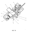
figures 5a à 5g sont des vues en coupe du bloc d'extraction selon une autre forme d'exécution de l'invention, montrant des étapes dans un cycle d'opération de la machine de l'introduction d'une capsule jusqu'à l'extraction de la capsule ; - Les
figures 6a à 6c sont des figures en perspective du bloc d'extraction de la variante illustrée dans lesfigures 5a à 5g , lafigure 6a illustrant le bloc d'extraction prêt pour l'introduction d'une capsule, lafigure 6b dans une position lors de l'injection d'eau dans la capsule et de l'extraction d'une boisson, et lafigure 6c dans la position d'éjection de la capsule après extraction, des parties du bloc d'extraction étant enlevées pour une meilleure visibilité du porte-capsule.
- The
figure 1 a is a perspective view of an extraction block of an apparatus for making a drink from a capsule according to the invention; -
Figure 1b is a perspective view in section of the extraction block according to thefigure 1 at ; - The
figure 1 c is a top view of the extraction block according to thefigure 1a ; - The
figure 1d is another sectional view of the extraction block according to thefigure 1a ; - The
figure 2a is another perspective view in section of the extraction block according to thefigure 1 a , with the injection head in the high position (open), before introduction of a capsule; - The
figure 2b is a view similar to thefigure 2a , showing the introduction of a capsule, falling into a housing of a capsule holder of the apparatus; - The
Figure 2c is a view similar to thefigure 2a , showing the capsule in the housing of the capsule holder of the device; - The
figure 2d is a figure similar to thefigure 2a with a capsule in the capsule holder housing and the injection head in the low (closed) position ready for the introduction of pressurized water; - The
figure 2e is a figure similar to thefigure 2a showing the injection head being raised and the capsule after use being ejected; - The
figure 2f is a figure similar to thefigure 2e showing the injection head almost completely raised and the capsule after use being evacuated; - The
figure 3 is a perspective view of the capsule holder and the ejection mechanism of the capsule; - The
figure 4 is a perspective view in section of the capsule-holder with an ejection mechanism according to a second variant; - The
Figures 5a to 5g are sectional views of the extraction block according to another embodiment of the invention, showing steps in a cycle of operation of the machine from the introduction of a capsule to the extraction of the capsule; - The
Figures 6a to 6c are perspective figures of the extraction block of the variant illustrated in theFigures 5a to 5g , thefigure 6a illustrating the extraction block ready for the introduction of a capsule, thefigure 6b in a position during the injection of water into the capsule and the extraction of a beverage, and theFigure 6c in the position of ejection of the capsule after extraction, parts of the extraction block being removed for better visibility of the capsule-holder.
Faisant référence aux figures, plus particulièrement aux
Le porte-capsule 8 comprend un logement 18 avec une paroi latérale 20 et une paroi d'extraction 22 formant le fond du logement 18. La paroi latérale 20 du logement a une forme évasée tronquée correspondant à la forme de la capsule 3 destinée à être reçue dans le logement. La paroi d'extraction peut avoir une ou plusieurs pointes de perforation et un ou plusieurs orifices pour l'écoulement du produit liquide extrait de la capsule après perforation. La paroi d'extraction et le logement du porte-capsule, ainsi que la capsule peuvent avantageusement être réalisés tels que décrits dans le brevets
Le porte-capsule selon l'invention comprend en outre un mécanisme d'éjection de la capsule 24 qui sera décrit plus en détail ci-dessous.The capsule holder according to the invention further comprises an ejection mechanism of the
La tête d'injection 10 comprend une paroi d'injection 26 avec des pointes de perforation 28 et un canal d'alimentation d'eau sous pression 30 pour l'injection d'eau à travers la paroi supérieure 32 de la capsule quand la tête d'injection est fermée contre le porte-capsule 8, tel qu'illustré dans la
La tête d'injection est amovible entre une position d'ouverture permettant l'introduction d'une capsule dans le logement 18 du porte-capsule 8, tel qu'illustré dans la
Le déplacement de la tête d'injection est actionné par le mécanisme d'ouverture et fermeture 12, ce mécanisme comprenant au moins deux bras ou paires de bras articulés 36a, 36b. Un bras ou paire de bras 36a est fixé de manière pivotante 38a sur le corps 6 du bloc d'extraction et un autre bras ou paire de bras 36b est fixé de manière pivotante 38b sur la tête d'injection, les deux bras (ou deux paires de bras) étant articulés l'un par rapport à l'autre autour d'un axe d'articulation 38c. L'axe de rotation 38a du premier bras articulé 36a est solidaire d'un levier 40 qui, dans la forme d'exécution illustrée, est destiné à être commandé manuellement par un utilisateur pour la rotation du premier bras articulé 36a.The displacement of the injection head is actuated by the opening and
Le premier bras (ou paires de bras) articulé 36a est plus court que le deuxième bras (ou paires de bras) articulé 36b afin de réduire l'encombrement du bloc d'extraction, notamment le volume nécessaire pour les déplacements des bras articulés. Le couple nécessaire pour le déplacement de la tête d'injection en position haute est faible. Par contre, pour la fermeture hermétique de la tête d'injection contre la collerette de la capsule et le rebord du porte-capsule, tenant compte des pressions exercées lors de l'injection d'eau sous pression, la force d'appui doit être grande. Les bras articulés permettant un grand déplacement à faible couple au début du mouvement de fermeture et un faible déplacement à force élevée pour la fermeture. Le verrouillage dans la position fermée est assuré lorsque les bras articulés 36a, 36b sont alignés ou ont légèrement passé le point d'alignement, tel qu'illustré dans la
Le mécanisme d'éjection de la capsule 24 comprend un poussoir d'éjection 42 couplé à un tirant 44, et un ressort de rappel 46.The mechanism for ejecting the
Le ressort de rappel maintient le poussoir 42 dans une position en retrait (position basse) telle qu'illustrée dans la
Le tirant est ainsi libéré et repoussé par le ressort 46 dans sa position de retrait, tel qu'illustré dans la
Dans la variante selon la
Pour la préparation d'une boisson, la tête d'injection est dans sa position haute tel qu'illustré dans la
Dans une forme d'exécution, la combinaison de l'angle d'inclinaison (α) du canal, du poids, de la forme de la capsule et du coefficient de frottement de la capsule contre le canal est configurée pour assurer une vitesse de pointe (V) de la capsule au moment juste avant de buter contre la paroi latérale, entre 0,5ms-1 et 3,0ms-1, de préférence entre 1,0ms-1 et 2,0ms-1. L'énergie cinétique de la capsule est, par cette mesure, optimisée pour assurer que la capsule tombe dans le logement 18 de manière fiable et en position correcte.In one embodiment, the combination of channel tilt angle (α), weight, capsule shape, and coefficient of friction of the capsule against the channel is configured to provide a top speed. (V) of the capsule at the moment just before abutting against the side wall, between 0.5 ms -1 and 3.0 ms -1 , preferably between 1.0 ms -1 and 2.0 ms -1 . The kinetic energy of the capsule is, by this measure, optimized to ensure that the capsule falls into the
Dans une forme d'exécution, la capsule remplie d'une substance pour la préparation d'une boisson, a une répartition de poids telle que le centre de gravité G est dans la partie inférieure de la capsule, à savoir entre la ligne à mi-hauteur M et le fond. Cela permet d'améliorer l'orientation de la capsule lorsqu'elle tombe dans le logement 18 afin d'assurer qu'elle tombe de manière fiable. Le centre de gravité peut être abaissé en variant l'épaisseur et la forme de l'enveloppe de la capsule, par exemple en ayant un ajout de matière sur la paroi de fond de la capsule. Le fond de la capsule peut être plus épais que les parois latérales de la capsule.In one embodiment, the capsule filled with a substance for the preparation of a beverage, has a weight distribution such that the center of gravity G is in the lower part of the capsule, namely between the mid-line height M and the bottom. This improves the orientation of the capsule when it falls into the
Le centre de gravité peut être abaissé aussi en ne remplissant que partiellement l'enveloppe de la capsule d'une substance pour la préparation d'une boisson, à un niveau inférieur à 95%, de préférence inférieure à 90% du volume total de l'intérieur de la capsule.The center of gravity can also be lowered by filling only partially the capsule shell with a substance for the preparation of a beverage, at a level of less than 95%, preferably less than 90% of the total volume of the capsule. inside the capsule.
Le mécanisme d'ouverture et fermeture 12 est ensuite actionné par la rotation du levier 40 qui fait tourner le premier bras articulé 36a, qui fait pivoter à son tour le deuxième bras articulé 36b, faisant descendre la tête d'injection 10 jusqu'à ce qu'elle vienne en appui contre la capsule dans le logement 18 tel qu'illustré dans la
L'eau sous pression entre 5 et 12 bars est injectée par le canal d'alimentation 30 et rentre dans la capsule par les orifices percés par les points 28. Lorsque la pression d'eau à l'intérieur de la capsule atteint un certain niveau, le fond de la capsule descend contre les pointes de perforation de la paroi d'extraction 22 et la substance à extraire s'écoule à travers les orifices de la paroi d'extraction.The water under pressure between 5 and 12 bar is injected through the
Après la fin d'injection d'eau, la tête d'injection est remontée en actionnant le levier 40. Lors de la remontée, la tête d'injection engage le crochet 48 du mécanisme d'éjection qui, en étant relevé, remonte le poussoir 42 qui appuie sur la collerette 34 de la capsule et l'éjecte du logement 18. Le poussoir 42, guidé par des paliers 56 ou glissières effectue de préférence un mouvement curviligne ou rectiligne mais incliné vers l'orifice d'évacuation 16 pour mieux projeter la capsule 3 dans la direction de l'orifice d'évacuation.After the end of water injection, the injection head is raised by actuating the
La rotation des bras articulés 36a, 36b peut être effectuée manuellement comme pour la forme d'exécution illustrée, mais elle peut être également effectuée par un moteur. Le mécanisme d'ouverture et fermeture de la tête d'injection peut également être construit autrement, par exemple sous forme d'un actionneur linéaire avec un système vis-écrou, ou par un système hydraulique.The rotation of the articulated
Dans la première forme d'exécution illustrée, l'axe IN du canal d'introduction 14 de la capsule n'est pas aligné sur un même axe EV que l'orifice d'évacuation 16 de la capsule. Cela permet de former une butée arrêtant la capsule et la faisant tomber dans le logement 18 du porte-capsule vers la fin de la descente dans le canal d'introduction 14. Dans la forme d'exécution illustrée, l'orifice d'évacuation est dirigé à un angle β de préférence entre 30 et 50 degrés, par exemple environ 45 degrés d'un plan vertical PV traversant l'axe IN du canal d'introduction (voir
Faisant maintenant référence aux
Dans cette variante, le mécanisme d'évacuation de la capsule 24' comprend un rail d'évacuation 60 ainsi qu'un dispositif de verrouillage 62 du porte-capsule 8'. Le porte capsule 8' est monté de manière pivotante autour d'un axe de rotation 64, par rapport au corps 6 du bloc d'extraction. Le rail d'évacuation 60 est solidaire du corps 6 du bloc d'extraction et comprend de préférence deux parties de rail 60a, 60b, tel qu'illustré dans la
La distance de la surface supérieure 61 du rail d'évacuation 60 par rapport à l'axe de pivotement 64 du porte-capsule, est plus grande vers l'extrémité libre 63 (R1) que la distance de la surface supérieure du rail d'évacuation par rapport à l'axe de pivotement à proximité du corps du bloc d'extraction (R2). Ainsi, lorsque le porte-capsule pivote de sa position d'extraction tel qu'illustré dans la
La rotation du porte-capsule de sa position d'extraction à la position d'évacuation est effectuée par un ressort 65, dans l'exemple illustré un ressort toroïdal, mais beaucoup d'autres formes de ressort et de mécanismes de rotation de la capsule peuvent être envisagés dans le cadre de cette invention. La rotation de la capsule peut également être entraînée par un moteur ou actuateur électrique.The rotation of the cartridge-holder from its extraction position to the evacuation position is effected by a
Le retour du porte capsule de sa position d'évacuation à la position d'extraction est assuré par un bras de rappel 66 (voir
Le dispositif de verrouillage 62 du porte-capsule comprend un corps amovible 74 avec un doigt de verrouillage 75 en appui contre une épaule 76 du porte-capsule lorsque il est dans sa position d'extraction et le corps amovible est dans sa position de verrouillage, tel qu'illustré dans la
Le doigt de verrouillage 60 peut avoir une surface oblique 85 agissant comme surface de came pour remonter le doigt de verrouillage lorsque le porte-capsule est pivoté de retour dans sa position d'extraction. En effet, le doigt de verrouillage 75 est déjà dans sa position basse avant que le porte-capsule soit complètement retourné dans la position d'extraction et la surface de came oblique 85 permet au corps amovible de verrouillage de remonter pour permettre le passage de l'épaule 76 sous le doigt de verrouillage qui est repoussé ensuite dans sa position de verrouillage engageant l'épaule 76 du porte-capsule.The locking
Dans les formes d'exécution illustrées, la capsule glisse par gravitation seule dans le canal d'introduction 14 jusqu'au logement 18. Toutefois, il est également possible de prévoir un doigt ou poussoir (non-illustré), par exemple à l'intérieur d'un couvercle (non-illustré) pivotant par rapport au bloc d'extraction, qui pousse la capsule le long du canal d'introduction jusqu'à sa position au-dessus du logement 18. Ce couvercle avec poussoir peut aussi agir sur un capteur de position détectant sa position fermée, indiquant que la capsule est introduite et que la tête d'injection peut être fermée sur le porte-capsule. D'autres moyens pour aider à convoyer la capsule le long du canal d'introduction jusqu'à sa position au-dessus du logement peuvent être réalisés sans sortir du cadre de l'invention. Par exemple, des faces opposées du canal peuvent comprendre des roulements sur ressorts qui sont écartés élastiquement quand la capsule est introduite dans le canal d'introduction, et ensuite qui poussent la capsule vers le logement 18 du porte-capsule en retournant à leur position de repos.In the illustrated embodiments, the capsule slides by gravitation alone in the
Claims (16)
- An appliance and container for preparing a beverage or a liquid food, the container (3) containing a substance to be extracted by introducing pressurized water into the container, the appliance comprising an extraction block (4) with an insertion channel (14) for the container, a container holder (8) with a recess, an extraction wall (22), a sidewall (20), an injection head (10) for injecting water into the container and an opening and closing mechanism (12) for accomplishing a relative motion between the container holder and the injection head for opening and closing the injection head at the container holder, the insertion channel being tilted at an angle (α) between 30 and 70 degrees with respect to a horizontal plane (HZ), characterized in that the angle (γ) between a portion of the sidewall (20) of the container holder remote from the insertion channel and the horizontal plane (HZ) is between 55 and 25 degrees and in that the opening and closing mechanism of the injection head comprises at least two articulated arms or pairs of arms, a first (36a) being pivotably mounted on the body (6) of the extraction block and the other (36b) pivotably mounted on the injection head, the first articulated arm having a shorter length than the second articulated arm.
- The appliance and container according to Claim 1, characterized in that the insertion channel is tilted at an angle between 40 and 50 degrees with respect to the horizontal plane, and the average angle between the sidewall and the horizontal plane is between 50 and 40 degrees.
- The appliance and container according to Claim 1 or 2, characterized in that the extraction block comprises an ejection opening (16) for the container oriented at a lateral angle β between 20 and 60 degrees, with respect to a vertical plane (PV) through an axis (IN) of the insertion channel.
- The appliance and container according to the foregoing claim, characterized in that the lateral angle β is between 30 and 50 degrees.
- The appliance and container according to any one of the foregoing claims, characterized in that it comprises an ejection mechanism (24) for the capsule comprising a ram (42) configured to engage with the underside of the flange of the container when the injection head is raised to the open position.
- The appliance and container according to the foregoing claim, characterized in that the container ejection mechanism comprises a tie rod (44) or portion of a tie rod joined to the ram and comprising a hook (48) configured to engage with a shoulder or hook (50) of the injection head when it is raised.
- The appliance and container according to any one of the two foregoing claims, characterized in that the ejection mechanism comprises a return spring (46) pushing the ram (42) into a retracted position allowing the insertion of a container into the recess of the container holder.
- The appliance and container according to any one of the three foregoing claims, characterized in that the container ejection mechanism comprises a cam (54) engaging with the tire rod when the injection head approaches its open position in order to free the tie rod from the injection head.
- The appliance and container according to any one of Claims 1 through 4, characterized in that the container holder is mounted pivotably with respect to the body (6) of the extraction block (4), the container holder being pivotable from an extraction position to a container ejection position, the appliance also comprising a container ejection mechanism comprising a rail configured to support the lower rim of the container when the container holder is pivoted from its extraction position to its ejection position.
- The appliance and container according to the foregoing claim, characterized in that the rail has a shape such that the distance between the rail and the pivot axis of the container holder increases from the extraction position to the ejection position.
- The appliance and container according to Claim 5 or 6, characterized in that the rail has a curved, smooth shape.
- The appliance and container according to one of the foregoing claims, characterized in that the container has a weight distribution such that the center of gravity G is in the lower portion of the container.
- The appliance and container according to one of the foregoing claims, characterized in that the container is only partially filled to a level of less than 90% of the total volume of the interior of the container.
- The appliance and container according to one of the foregoing claims, characterized in that the combination of the angle of inclination (α) of the channel, the weight, the shape of the container and the coefficient of friction of the capsule against the channel is configured to ensure a peak speed of the container, at the moment just prior to striking the lateral wall of the recess of the container holder, of between 0.5ms-1 and 3.0ms-1, preferably between 1.0ms-1 and 2.0ms-1.
- The appliance and container according to one of Claims 9 through 11, characterized in that the rail comprises two rail portions (60a, 60b) arranged on either side of the recess (18) of the container holder.
- The appliance and container according to one of Claims 9 through 12, characterized in that the container holder comprises a rim (35') with hollow portions (35a, 35b) which are positioned under the discharge rails when the container holder is in the high position.
Priority Applications (3)
| Application Number | Priority Date | Filing Date | Title |
|---|---|---|---|
| EP09718825.4A EP2265156B1 (en) | 2008-03-14 | 2009-03-13 | Apparatus and capsule for making a drink |
| EP13158706.5A EP2679120B1 (en) | 2008-03-14 | 2009-03-13 | Appliance and capsule for preparing a beverage |
| PL09718825T PL2265156T3 (en) | 2008-03-14 | 2009-03-13 | Apparatus and capsule for making a drink |
Applications Claiming Priority (3)
| Application Number | Priority Date | Filing Date | Title |
|---|---|---|---|
| EP08004876 | 2008-03-14 | ||
| EP09718825.4A EP2265156B1 (en) | 2008-03-14 | 2009-03-13 | Apparatus and capsule for making a drink |
| PCT/IB2009/051047 WO2009113035A2 (en) | 2008-03-14 | 2009-03-13 | Apparatus and capsule for making a drink |
Related Child Applications (2)
| Application Number | Title | Priority Date | Filing Date |
|---|---|---|---|
| EP13158706.5A Division EP2679120B1 (en) | 2008-03-14 | 2009-03-13 | Appliance and capsule for preparing a beverage |
| EP13158706.5 Division-Into | 2013-03-12 |
Publications (2)
| Publication Number | Publication Date |
|---|---|
| EP2265156A2 EP2265156A2 (en) | 2010-12-29 |
| EP2265156B1 true EP2265156B1 (en) | 2013-05-15 |
Family
ID=40810186
Family Applications (2)
| Application Number | Title | Priority Date | Filing Date |
|---|---|---|---|
| EP09718825.4A Active EP2265156B1 (en) | 2008-03-14 | 2009-03-13 | Apparatus and capsule for making a drink |
| EP13158706.5A Active EP2679120B1 (en) | 2008-03-14 | 2009-03-13 | Appliance and capsule for preparing a beverage |
Family Applications After (1)
| Application Number | Title | Priority Date | Filing Date |
|---|---|---|---|
| EP13158706.5A Active EP2679120B1 (en) | 2008-03-14 | 2009-03-13 | Appliance and capsule for preparing a beverage |
Country Status (16)
| Country | Link |
|---|---|
| US (1) | US8875617B2 (en) |
| EP (2) | EP2265156B1 (en) |
| JP (1) | JP5451650B2 (en) |
| CN (1) | CN101969823B (en) |
| AU (1) | AU2009223206B2 (en) |
| BR (1) | BRPI0909750B1 (en) |
| CA (1) | CA2716536A1 (en) |
| DK (1) | DK2265156T3 (en) |
| ES (2) | ES2419656T3 (en) |
| HK (1) | HK1195860A1 (en) |
| HR (1) | HRP20170195T1 (en) |
| PL (2) | PL2679120T3 (en) |
| PT (1) | PT2679120T (en) |
| RU (1) | RU2501512C2 (en) |
| TW (1) | TWI469756B (en) |
| WO (1) | WO2009113035A2 (en) |
Cited By (1)
| Publication number | Priority date | Publication date | Assignee | Title |
|---|---|---|---|---|
| EP2915465A1 (en) | 2014-03-06 | 2015-09-09 | Nestec S.A. | Beverage production device for receiving a capsule for the preparation of a beverage |
Families Citing this family (108)
| Publication number | Priority date | Publication date | Assignee | Title |
|---|---|---|---|---|
| US7640843B2 (en) | 2003-01-24 | 2010-01-05 | Kraft Foods R & D, Inc. | Cartridge and method for the preparation of beverages |
| CN100544647C (en) * | 2007-06-15 | 2009-09-30 | 宁波三A集团电器有限公司 | Automatically the mechanism that comes off of coffee bag in coffee maker |
| CL2008002963A1 (en) | 2007-10-04 | 2010-01-22 | Nestec Sa | Heating device for a machine for the preparation of liquid food or drink, comprising a thermal unit with a metallic mass, through which the liquid circulates, and accumulates heat and supplies it to the liquid, and has one or more insured electrical components rigidly to the thermal unit; and machine. |
| EP2209407B1 (en) | 2007-10-04 | 2017-01-25 | Nestec S.A. | Integrated heater for a beverage preparation device |
| WO2009043630A2 (en) | 2007-10-04 | 2009-04-09 | Nestec S.A. | Beverage brewing unit |
| RU2497429C2 (en) | 2008-04-22 | 2013-11-10 | Нестек С.А. | Modula design device for preparation of beverages |
| EP2147621B1 (en) * | 2008-07-24 | 2011-07-06 | Gruppo Cimbali S.p.A. | An apparatus for the preparation of coffee-based beverages from pre-packaged pods or capsules |
| JP5608647B2 (en) * | 2008-08-08 | 2014-10-15 | ネステク ソシエテ アノニム | Beverage device with carrying handle and configurable appearance and secondary functions |
| IT1399318B1 (en) * | 2010-04-09 | 2013-04-16 | Rapparini | CAPSULE WITH INTERNAL VERTICAL FLOW OF PRINTED FLOW FOR INJECTION OR FOR THERMOFORMING AND HERMETICALLY CLOSED TO OBTAIN EXPRESS TYPE OF INFUSIONS OR DRINKS FROM HYDROSULUBLE PRODUCTS AND ITS USING MACHINE. |
| US20150125586A1 (en) * | 2010-05-03 | 2015-05-07 | Apiqe | Beverage system with flavor pod dispenser |
| FR2960401B1 (en) * | 2010-05-25 | 2012-05-25 | Cie Mediterraneenne Des Cafes | INFUSION GROUP FOR BEVERAGE PRODUCTION MACHINE |
| USD647399S1 (en) | 2010-09-02 | 2011-10-25 | Keurig, Incorporated | Beverage cartridge |
| US8361527B2 (en) | 2010-09-02 | 2013-01-29 | Keurig, Incorporated | Beverage cartridge |
| USD647398S1 (en) | 2010-09-02 | 2011-10-25 | Keurig Incorporated | Beverage cartridge |
| USD637484S1 (en) | 2010-09-02 | 2011-05-10 | Keurig, Incorporated | Beverage cartridge |
| PT2621317E (en) | 2010-09-28 | 2014-05-19 | Nestec Sa | Device and method for retrieving a capsule from a beverage production apparatus |
| US8950315B2 (en) * | 2010-11-15 | 2015-02-10 | Conair Corporation | Brewed beverage appliance and method |
| IT1404386B1 (en) * | 2011-02-25 | 2013-11-22 | Biepi S R L | PERFECTED EXPULSION DEVICE FOR PODS OR TABLETS IN A MACHINE FOR THE PRODUCTION OF HOT OR COFFEE DRINKS |
| CN103561618B (en) * | 2011-03-09 | 2016-05-18 | Imper股份公司 | For distributing the machine of brewed liquid |
| KR20140011380A (en) * | 2011-03-14 | 2014-01-28 | 네스텍 소시에테아노님 | Automatic beverage machine |
| PT105712A (en) * | 2011-05-19 | 2012-11-19 | Novadelta Com E Ind De Cafes S A | DEVICE FOR EXTRACTION OF CAPSULES, PROCESS OF OPERATION OF THIS AND MACHINE INCLUDING THE AID DEVICE |
| ITRM20110458A1 (en) * | 2011-09-05 | 2013-03-06 | Iacobucci Hf Electronics S P A | POD HOLDER DEVICE FOR BEVERAGE DISPENSING MACHINE |
| ITVR20110180A1 (en) * | 2011-09-19 | 2013-03-20 | Caffita System Spa | INFUSION DEVICE FOR THE PRODUCTION OF DRINKS BY USING CARTRIDGES, WHICH CAPSULES OR PODS |
| US10034570B2 (en) | 2011-11-09 | 2018-07-31 | LaVit Technology LLC | Capsule based system for preparing and dispensing a beverage |
| US10080459B2 (en) | 2011-11-09 | 2018-09-25 | La Vit Technology Llc | Capsule-based system for preparing and dispensing a beverage |
| HUE031109T2 (en) * | 2012-01-25 | 2017-06-28 | Qbo Coffee Gmbh | Brewing module |
| EP2811872B1 (en) | 2012-02-09 | 2016-11-30 | Keurig Green Mountain, Inc. | Beverage forming device and method with moving beverage cartridge holder |
| ITTO20120503A1 (en) * | 2012-06-08 | 2013-12-09 | Lavazza Luigi Spa | DISPENSING UNIT FOR MACHINES FOR THE PREPARATION OF DRINKS BY CAPSULES |
| DE102012108653A1 (en) | 2012-08-20 | 2014-02-20 | Eugster/Frismag Ag Elektrohaushaltgeräte | Brewing device and method for operating a brewing device |
| CN104768432B (en) * | 2012-08-21 | 2018-03-30 | 布瑞威利私人有限公司 | Portable filter for capsule |
| EP2906089B1 (en) * | 2012-10-09 | 2018-11-07 | Nestec S.A. | Beverage machine |
| KR20150136533A (en) | 2013-04-03 | 2015-12-07 | 2266170 온타리오 인크. | Capsule machine and components |
| WO2014183783A1 (en) | 2013-05-14 | 2014-11-20 | Delica Ag | Brewing module and system for preparing a beverage |
| US9320382B2 (en) | 2013-07-15 | 2016-04-26 | La Vit Technology Llc | Capsule based system for preparing and dispensing a beverage |
| ITVR20130194A1 (en) * | 2013-08-09 | 2015-02-10 | Caffita System Spa | HORIZONTAL GROUP FOR THE PREPARATION OF BEVERAGES USING CAPSULES CONTAINING POWDERED FOODSTUFFS |
| US10136754B2 (en) | 2014-01-17 | 2018-11-27 | Keurig Green Mountain, Inc. | Beverage machine cartridge holder |
| US9474406B2 (en) | 2014-01-17 | 2016-10-25 | Keurig Green Mountain, Inc. | Apparatus with beverage cartridge holder having movable outlet |
| US9788682B2 (en) * | 2014-02-25 | 2017-10-17 | Newco Enterprises, Inc. | Beverage brewing device for automatically brewing and dispensing single cup quantities of beverage through a vending machine with minimal manual participation |
| CN103948318B (en) * | 2014-02-26 | 2016-08-31 | 宁波全景电器技术有限公司 | A kind of clamping plate and there is the opening and closing structure of these clamping plate |
| WO2015173124A1 (en) | 2014-05-12 | 2015-11-19 | Nestec S.A. | Beverage brewing unit particularly for machines for preparing beverages from capsules |
| PT3142525T (en) * | 2014-05-12 | 2018-07-02 | Nestle Sa | Beverage brewing unit particularly for machines for preparing beverages from capsules |
| MX2017002220A (en) | 2014-08-21 | 2017-05-03 | Nestec Sa | Inter-operable capsule dispensing unit and beverage preparation machine. |
| EP2989943B1 (en) * | 2014-09-01 | 2020-07-08 | Eugster/Frismag AG | Brewing device for extracting a portion capsule |
| JP2017534350A (en) | 2014-10-08 | 2017-11-24 | ネステク ソシエテ アノニム | Reconfigurable beverage preparation machine |
| BR112017004983A2 (en) | 2014-10-08 | 2017-12-05 | Nestec Sa | beverage extraction machine extraction unit |
| WO2016087474A1 (en) * | 2014-12-01 | 2016-06-09 | Eugster / Frismag Ag | Single-serve-capsule machine and method for operating a single-serve-capsule machine |
| WO2016086780A1 (en) * | 2014-12-04 | 2016-06-09 | 九阳股份有限公司 | Horizontal rotary reconstituted machine and method thereof for preparing drink |
| NL2014557B1 (en) * | 2015-03-31 | 2017-01-06 | Bravilor Holding Bv | Beverage preparation device. |
| ES2896893T3 (en) * | 2015-07-02 | 2022-02-28 | Nestle Sa | Compact integration of a capsule handling device |
| JP6820914B2 (en) | 2015-09-18 | 2021-01-27 | ソシエテ・デ・プロデュイ・ネスレ・エス・アー | Removing the capsule from the capsule holder |
| PT3364832T (en) | 2015-10-23 | 2021-06-24 | Nestle Sa | User interface of beverage preparation machine |
| RU2018118590A (en) | 2015-10-23 | 2019-11-25 | Сосьете Де Продюи Нестле С.А. | DEVICE WITH EXTENDABLE FUNCTIONALITY FOR PREPARING A DRINK |
| US20170135516A1 (en) * | 2015-11-12 | 2017-05-18 | Giancarlo Fantappiè | System for mixing and dispensing a beverage |
| RU2729297C2 (en) | 2015-11-27 | 2020-08-05 | Сосьете Де Продюи Нестле С.А. | Method of monitoring consumption of containers for a beverage or a food product |
| ES2939370T3 (en) | 2016-01-12 | 2023-04-21 | Freezio Ag | Dispensing system with cartridge holder |
| FR3047159A1 (en) * | 2016-02-01 | 2017-08-04 | Rolland Versini | ASSEMBLY FOR THE AUTOMATIC PREPARATION AND DISTRIBUTION OF BEVERAGES |
| TWI642395B (en) | 2016-02-23 | 2018-12-01 | 耐斯泰克公司 | A container and a computer program executable on one or more processors of a code processing subsystem of a beverage or foodstuff preparation machine, a beverage or foodstuff preparation system and a method of preparing a beverage or foodstuff using the |
| PL3420497T3 (en) | 2016-02-23 | 2022-02-07 | Société des Produits Nestlé S.A. | Code and container of system for preparing a beverage or foodstuff |
| TW201741203A (en) | 2016-02-23 | 2017-12-01 | Nestec Sa | Code and container of system for preparing a beverage or foodstuff |
| TWI721084B (en) | 2016-02-23 | 2021-03-11 | 瑞士商雀巢製品股份有限公司 | Container for a beverage or foodstuff preparation machine, attachment configured for attachment to the container, beverage or foodstuff preparation system, attachment configured for attachment to the machine, method of encoding preparation information, method of preparing the beverage or foodstuff, use of a code for encoding preparation information on the container, and computer program product |
| TWI722097B (en) | 2016-02-23 | 2021-03-21 | 瑞士商雀巢製品股份有限公司 | Container for a beverage preparation machine or foodstuff preparation machine, attachment attached to the container and method of encoding preparation information |
| TWI788279B (en) | 2016-02-23 | 2023-01-01 | 瑞士商雀巢製品股份有限公司 | Code, method and container of system for preparing a beverage or foodstuff, code and method for encoding preparation information, and non-transitory computer readable medium including computer program |
| US20170252995A1 (en) * | 2016-03-03 | 2017-09-07 | Juicero, Inc. | Juicer cartridge with outlet separator |
| US20170252994A1 (en) * | 2016-03-03 | 2017-09-07 | Juicero, Inc. | Juicing system with juicer cartridge restraints |
| US20170252999A1 (en) * | 2016-03-03 | 2017-09-07 | Juicero, Inc. | Juicer with juicer cartridge orientation feature |
| US20170252991A1 (en) * | 2016-03-03 | 2017-09-07 | Juicero, Inc. | Juicer with flexible seal |
| US20170252993A1 (en) * | 2016-03-03 | 2017-09-07 | Juicero, Inc. | Juicer cartridge with coupling |
| US20170253000A1 (en) * | 2016-03-03 | 2017-09-07 | Juicero, Inc. | Juicer with locking mechanism |
| US20170252998A1 (en) * | 2016-03-03 | 2017-09-07 | Juicero, Inc. | Juicer cartridge with flow disruptor |
| US20170251863A1 (en) * | 2016-03-03 | 2017-09-07 | Juicero, Inc. | Angled juicing system |
| US20170252990A1 (en) * | 2016-03-03 | 2017-09-07 | Juicero, Inc. | Juicer cartridge geometry |
| US20170252997A1 (en) * | 2016-03-03 | 2017-09-07 | Juicero, Inc. | Juicer cartridge with sanitary seal |
| US20170252996A1 (en) * | 2016-03-03 | 2017-09-07 | Juicero, Inc. | Juicer cartridge with secondary flow channel |
| EP3439514B1 (en) | 2016-04-07 | 2021-06-02 | Société des Produits Nestlé S.A. | Beverage preparation machine with two-liquid circuits and electronic device for controlling the same |
| US11178996B2 (en) * | 2016-05-23 | 2021-11-23 | Societe Des Produits Nestle S.A. | Removal of a capsule from a capsule holder |
| CH712695A1 (en) | 2016-07-07 | 2018-01-15 | Mühlemann Ip Gmbh | One-serving pack for making a beverage from a beverage concentrate. |
| ES2726821T5 (en) | 2016-07-25 | 2023-06-06 | Nestle Sa | Machine and electronic device for the personalized preparation of drinks |
| NL2017279B1 (en) | 2016-08-03 | 2018-02-14 | Douwe Egberts Bv | System for preparing a beverage |
| NL2017283B1 (en) | 2016-08-03 | 2018-02-14 | Douwe Egberts Bv | System and apparatus for preparing a beverage |
| NL2017281B1 (en) | 2016-08-03 | 2018-02-14 | Douwe Egberts Bv | System for preparing a beverage |
| NL2017284B1 (en) | 2016-08-03 | 2018-02-14 | Douwe Egberts Bv | System and method for preparing a beverage field and background |
| NL2017278B1 (en) | 2016-08-03 | 2018-02-14 | Douwe Egberts Bv | System, apparatus, method, capsule and kit of capsules for preparing a beverage |
| NL2017277B1 (en) | 2016-08-03 | 2018-02-14 | Douwe Egberts Bv | Apparatus and method for preparing a beverage and system comprising the apparatus and an exchangeable capsule |
| NL2017285B1 (en) | 2016-08-03 | 2018-02-14 | Douwe Egberts Bv | System, apparatus, method, capsule and kit of capsules for preparing a beverage |
| NL2019216B1 (en) | 2016-08-03 | 2018-05-04 | Douwe Egberts Bv | System for preparing a quantity of beverage suitable for consumption |
| US11643269B2 (en) | 2016-12-01 | 2023-05-09 | Bedford Systems, LLC | Container and opening arrangement for beverage production |
| IT201600130860A1 (en) * | 2016-12-23 | 2018-06-23 | Gruppo Gimoka S R L | INFUSER GROUP FOR THE PREPARATION OF DRINKS STARTING FROM DISPOSABLE CAPSULES |
| IT201700020604A1 (en) * | 2017-02-23 | 2018-08-23 | Bruno Bardazzi | Beverage preparation machine which uses pre-packed fillers suitable for this preparation |
| CN108567332A (en) * | 2017-03-08 | 2018-09-25 | 何宜佶 | beverage preparation system |
| RU2769663C2 (en) | 2017-05-23 | 2022-04-04 | Сосьете Де Продюи Нестле С.А. | Beverage preparation device with improved pump control |
| JP7245180B2 (en) | 2017-06-26 | 2023-03-23 | フレーツィオ アーゲー | beverage production equipment |
| AU2018312777B2 (en) | 2017-08-08 | 2023-08-24 | Societe Des Produits Nestle S.A. | Container with a code encoding a sequence of foodstuff or beverage preparation operations |
| JP7250781B2 (en) | 2017-10-06 | 2023-04-03 | ソシエテ・デ・プロデュイ・ネスレ・エス・アー | System using binary code to encode container, preparation machine and preparation information |
| EP3536637B1 (en) | 2018-03-05 | 2020-09-16 | Nootrie AG | Capsule for preparing a beverage |
| EP3768127B1 (en) * | 2018-03-22 | 2023-12-06 | Bedford Systems LLC | Puncture mechanism for beverage machine |
| NL2022190B1 (en) | 2018-12-12 | 2020-07-03 | Douwe Egberts Bv | Air purge groove |
| TWI689270B (en) * | 2019-01-04 | 2020-04-01 | 亞弘電科技股份有限公司 | Coffee capsule device |
| CN110074677A (en) * | 2019-04-27 | 2019-08-02 | 广东亿龙电器科技有限公司 | A kind of automatic transducer package of new-type capsule machine is set |
| CN214017138U (en) * | 2020-09-09 | 2021-08-24 | 富港电子(徐州)有限公司 | Drawer type capsule coffee machine |
| CA3239788A1 (en) | 2021-12-22 | 2023-06-29 | Marcel Fankhauser | Beverage preparation by centrifugation with reliable capsule transfer |
| CN118369025A (en) | 2021-12-22 | 2024-07-19 | 雀巢产品有限公司 | Beverage preparation by stable capsule centrifugation |
| CA3239808A1 (en) | 2021-12-22 | 2023-06-29 | Societe Des Produits Nestle S.A. | Beverage preparation with compact conditioning chamber |
| US20240162369A1 (en) | 2021-12-22 | 2024-05-16 | M10 Solar Equipment GmbH | Process and apparatus for manufacturing solar panels |
| WO2023118246A1 (en) | 2021-12-22 | 2023-06-29 | Société des Produits Nestlé S.A. | Beverage preparation with a flexible outlet valve |
| AU2022422172A1 (en) | 2021-12-22 | 2024-05-02 | Société des Produits Nestlé S.A. | Beverage preparation with a stable outlet valve |
| WO2023198819A1 (en) | 2022-04-14 | 2023-10-19 | Société des Produits Nestlé S.A. | Centrifugal chamber with capsule opening elements |
| AU2023254439A1 (en) | 2022-04-14 | 2024-09-12 | Société des Produits Nestlé S.A. | Centrifugal beverage chamber with closure fastener |
| WO2023198823A1 (en) | 2022-04-14 | 2023-10-19 | Société des Produits Nestlé S.A. | Centrifugal chamber with capsule positioning guide |
Family Cites Families (20)
| Publication number | Priority date | Publication date | Assignee | Title |
|---|---|---|---|---|
| US3584767A (en) * | 1969-05-12 | 1971-06-15 | Joseph Carl Dawson | Canister tapping device |
| JPS61119220A (en) * | 1984-11-14 | 1986-06-06 | ソシエテ デ プロデユイ ネツスル ソシエテ アノニム | Extractor for coffee,etc. |
| AU650064B2 (en) | 1990-10-31 | 1994-06-09 | Monodor S.A. | Method for preparing a liquid product and device for implementing same |
| FR2709655B1 (en) * | 1993-09-06 | 1995-11-24 | Cafes Cie Mediterraneenne | Express coffee machine using ground coffee packaging of the pre-dosed tablet type. |
| CA2178595C (en) * | 1993-12-20 | 2006-11-21 | Jean-Pierre Blanc | Automatic machine for the preparation of hot beverage infusions |
| US6079315A (en) * | 1999-01-19 | 2000-06-27 | Keurig, Inc. | Beverage filter cartridge holder |
| US7063238B2 (en) * | 2001-06-29 | 2006-06-20 | Robert Hale | Cartridge ejector for a beverage dispensing machine |
| ES2226531B1 (en) * | 2002-07-04 | 2006-05-16 | Francisco Navarro Alcantara | PROCEDURE, MACHINE AND PACK FOR THE PREPARATION AND EXPEDITION OF HOT AND COLD DRINKS. |
| ITPN20020093A1 (en) * | 2002-12-02 | 2004-06-03 | Necta Vending Solutions Spa | MECHANICAL AND FLUID DYNAMIC CONTROL INFUSER GROUP. |
| DK1444932T3 (en) * | 2003-02-07 | 2006-06-06 | Nestec Sa | Extraction module with linear closure to produce a beverage under pressure from a capsule |
| US6955116B2 (en) * | 2003-06-13 | 2005-10-18 | Robert Hale | Beverage dispensing machine including cartridge ejector assembly |
| EP1495702A1 (en) | 2003-07-10 | 2005-01-12 | Nestec S.A. | Device for the extraction of a cartridge |
| DK1500357T3 (en) | 2003-07-23 | 2006-06-19 | Monodor Sa | Process for preparing a beverage from a capsule and device for initiating the process |
| US7219596B2 (en) * | 2004-08-19 | 2007-05-22 | Carrier Commerical Refrigeration, Inc. | Coffee brewer with loading and ejection mechanism for a coffee cartridge |
| ITMI20042350A1 (en) * | 2004-12-09 | 2005-03-09 | Saeco Internat Group S P A | DELIVERY HEAD FOR ESPRESSO COFFEE MACHINES |
| WO2007016977A1 (en) | 2005-08-05 | 2007-02-15 | Delica Ag | Device for extracting an extraction product contained in a capsule by means of a liquid extraction agent |
| ITGE20050072A1 (en) * | 2005-09-14 | 2007-03-15 | Termozeta Spa | ESPRESSO COFFEE MACHINE. |
| ATE411757T2 (en) * | 2005-09-27 | 2008-11-15 | Nestec Sa | EXTRACTION MODULE FOR A CAPSULE BASED BEVERAGE MACHINE |
| ITGE20050077A1 (en) * | 2005-10-19 | 2007-04-20 | Ariete Spa | DEVICE FOR EXPULSION OF PRECONFORMED EXHAUSTED CHARGES FOR ESPRESSO COFFEE MACHINES. |
| ITMI20061307A1 (en) | 2006-07-06 | 2008-01-07 | Perfect Steam Appliances Ltd | INFUSION GROUP FOR MACHINE FOR THE PREPARATION OF DRINKS |
-
2009
- 2009-03-13 WO PCT/IB2009/051047 patent/WO2009113035A2/en active Application Filing
- 2009-03-13 EP EP09718825.4A patent/EP2265156B1/en active Active
- 2009-03-13 DK DK09718825.4T patent/DK2265156T3/en active
- 2009-03-13 TW TW98108180A patent/TWI469756B/en not_active IP Right Cessation
- 2009-03-13 EP EP13158706.5A patent/EP2679120B1/en active Active
- 2009-03-13 AU AU2009223206A patent/AU2009223206B2/en active Active
- 2009-03-13 ES ES09718825T patent/ES2419656T3/en active Active
- 2009-03-13 ES ES13158706.5T patent/ES2615452T3/en active Active
- 2009-03-13 CA CA2716536A patent/CA2716536A1/en not_active Abandoned
- 2009-03-13 BR BRPI0909750 patent/BRPI0909750B1/en not_active IP Right Cessation
- 2009-03-13 PT PT131587065T patent/PT2679120T/en unknown
- 2009-03-13 PL PL13158706T patent/PL2679120T3/en unknown
- 2009-03-13 CN CN200980108958XA patent/CN101969823B/en active Active
- 2009-03-13 RU RU2010142013/12A patent/RU2501512C2/en active
- 2009-03-13 PL PL09718825T patent/PL2265156T3/en unknown
- 2009-03-13 US US12/736,139 patent/US8875617B2/en active Active
- 2009-03-13 JP JP2010550322A patent/JP5451650B2/en not_active Expired - Fee Related
-
2014
- 2014-06-24 HK HK14105995.8A patent/HK1195860A1/en not_active IP Right Cessation
-
2017
- 2017-02-06 HR HRP20170195TT patent/HRP20170195T1/en unknown
Cited By (1)
| Publication number | Priority date | Publication date | Assignee | Title |
|---|---|---|---|---|
| EP2915465A1 (en) | 2014-03-06 | 2015-09-09 | Nestec S.A. | Beverage production device for receiving a capsule for the preparation of a beverage |
Also Published As
| Publication number | Publication date |
|---|---|
| DK2265156T3 (en) | 2013-08-19 |
| WO2009113035A2 (en) | 2009-09-17 |
| US8875617B2 (en) | 2014-11-04 |
| EP2679120A3 (en) | 2014-03-26 |
| PT2679120T (en) | 2017-02-14 |
| CN101969823A (en) | 2011-02-09 |
| AU2009223206A1 (en) | 2009-09-17 |
| EP2679120A2 (en) | 2014-01-01 |
| CN101969823B (en) | 2013-05-29 |
| BRPI0909750A2 (en) | 2015-10-06 |
| EP2679120B1 (en) | 2016-11-09 |
| HRP20170195T1 (en) | 2017-04-07 |
| PL2679120T3 (en) | 2017-07-31 |
| BRPI0909750B1 (en) | 2019-12-03 |
| US20110000377A1 (en) | 2011-01-06 |
| WO2009113035A3 (en) | 2009-11-26 |
| ES2419656T3 (en) | 2013-08-21 |
| JP5451650B2 (en) | 2014-03-26 |
| TW201002255A (en) | 2010-01-16 |
| JP2011513023A (en) | 2011-04-28 |
| EP2265156A2 (en) | 2010-12-29 |
| RU2501512C2 (en) | 2013-12-20 |
| TWI469756B (en) | 2015-01-21 |
| RU2010142013A (en) | 2012-04-20 |
| AU2009223206B2 (en) | 2014-09-04 |
| PL2265156T3 (en) | 2013-10-31 |
| CA2716536A1 (en) | 2009-09-17 |
| ES2615452T3 (en) | 2017-06-07 |
| HK1195860A1 (en) | 2014-11-28 |
Similar Documents
| Publication | Publication Date | Title |
|---|---|---|
| EP2265156B1 (en) | Apparatus and capsule for making a drink | |
| EP1480540B1 (en) | Device for producing beverage by infusion | |
| EP2083662B1 (en) | Assembly comprising an appliance and a disposable capsule for producing a brewed drink, and capsule for such an assembly | |
| EP2020891B1 (en) | Machine for producing espresso-type coffee | |
| EP1208782B1 (en) | Percolation device | |
| EP1471815B1 (en) | Device for production of a drink by infusion | |
| EP2043489B1 (en) | Device and process for brewing a drink | |
| EP1827182B1 (en) | Automatic infused beverage dispenser comprising an infused product ejecting device | |
| WO2004071259A1 (en) | Extraction module with linear closure for the pressurised preparation of a drink from a capsule | |
| EP2833765B1 (en) | Device for preparing a beverage by infusion pod with a pivoting cradle | |
| FR2998463A1 (en) | BEVERAGE INFUSION BEVERAGE PREPARATION DEVICE WITH SWIVEL CRADLE | |
| FR2945925A1 (en) | DOMESTIC APPLIANCE FOR SERRATING FOOD WASTE CONTENT, CONTAINER AND RECOVERING THEM SEPARATELY. | |
| EP3262994B1 (en) | Device for preparing beverage by brewing a powder contained in a capsule | |
| FR2842089A1 (en) | Coffee making machine has infusion head, in which sachets of coffee are placed, cover which has hollow needles mounted on it swiveling down to perforate sachet | |
| AU2014262252B2 (en) | Apparatus and capsule for making a drink | |
| EP3285623A1 (en) | Jam detection system for an infusion beverage production machine | |
| FR2836625A1 (en) | Device for producing coffee drinks by infusion comprises chamber receiving doser comprising two parts which can be brought close together or spaced apart to close or open chamber | |
| FR2836624A1 (en) | Device for producing coffee drinks by infusion comprises chamber receiving doser comprising two parts which can be brought close together or spaced apart to close or open chamber |
Legal Events
| Date | Code | Title | Description |
|---|---|---|---|
| PUAI | Public reference made under article 153(3) epc to a published international application that has entered the european phase |
Free format text: ORIGINAL CODE: 0009012 |
|
| 17P | Request for examination filed |
Effective date: 20101012 |
|
| AK | Designated contracting states |
Kind code of ref document: A2 Designated state(s): AT BE BG CH CY CZ DE DK EE ES FI FR GB GR HR HU IE IS IT LI LT LU LV MC MK MT NL NO PL PT RO SE SI SK TR |
|
| AX | Request for extension of the european patent |
Extension state: AL BA RS |
|
| DAX | Request for extension of the european patent (deleted) | ||
| GRAP | Despatch of communication of intention to grant a patent |
Free format text: ORIGINAL CODE: EPIDOSNIGR1 |
|
| GRAS | Grant fee paid |
Free format text: ORIGINAL CODE: EPIDOSNIGR3 |
|
| GRAA | (expected) grant |
Free format text: ORIGINAL CODE: 0009210 |
|
| RAP1 | Party data changed (applicant data changed or rights of an application transferred) |
Owner name: MOCOFFEE AG |
|
| AK | Designated contracting states |
Kind code of ref document: B1 Designated state(s): AT BE BG CH CY CZ DE DK EE ES FI FR GB GR HR HU IE IS IT LI LT LU LV MC MK MT NL NO PL PT RO SE SI SK TR |
|
| REG | Reference to a national code |
Ref country code: CH Ref legal event code: EP Ref country code: GB Ref legal event code: FG4D Free format text: NOT ENGLISH |
|
| REG | Reference to a national code |
Ref country code: AT Ref legal event code: REF Ref document number: 611675 Country of ref document: AT Kind code of ref document: T Effective date: 20130615 |
|
| REG | Reference to a national code |
Ref country code: IE Ref legal event code: FG4D Free format text: LANGUAGE OF EP DOCUMENT: FRENCH |
|
| REG | Reference to a national code |
Ref country code: CH Ref legal event code: NV Representative=s name: REUTELER AND CIE SA, CH |
|
| REG | Reference to a national code |
Ref country code: DE Ref legal event code: R096 Ref document number: 602009015711 Country of ref document: DE Effective date: 20130711 |
|
| REG | Reference to a national code |
Ref country code: DK Ref legal event code: T3 |
|
| REG | Reference to a national code |
Ref country code: ES Ref legal event code: FG2A Ref document number: 2419656 Country of ref document: ES Kind code of ref document: T3 Effective date: 20130821 |
|
| REG | Reference to a national code |
Ref country code: SE Ref legal event code: TRGR |
|
| REG | Reference to a national code |
Ref country code: AT Ref legal event code: MK05 Ref document number: 611675 Country of ref document: AT Kind code of ref document: T Effective date: 20130515 |
|
| REG | Reference to a national code |
Ref country code: LT Ref legal event code: MG4D |
|
| REG | Reference to a national code |
Ref country code: NL Ref legal event code: VDEP Effective date: 20130515 |
|
| PG25 | Lapsed in a contracting state [announced via postgrant information from national office to epo] |
Ref country code: AT Free format text: LAPSE BECAUSE OF FAILURE TO SUBMIT A TRANSLATION OF THE DESCRIPTION OR TO PAY THE FEE WITHIN THE PRESCRIBED TIME-LIMIT Effective date: 20130515 Ref country code: GR Free format text: LAPSE BECAUSE OF FAILURE TO SUBMIT A TRANSLATION OF THE DESCRIPTION OR TO PAY THE FEE WITHIN THE PRESCRIBED TIME-LIMIT Effective date: 20130816 Ref country code: LT Free format text: LAPSE BECAUSE OF FAILURE TO SUBMIT A TRANSLATION OF THE DESCRIPTION OR TO PAY THE FEE WITHIN THE PRESCRIBED TIME-LIMIT Effective date: 20130515 Ref country code: NO Free format text: LAPSE BECAUSE OF FAILURE TO SUBMIT A TRANSLATION OF THE DESCRIPTION OR TO PAY THE FEE WITHIN THE PRESCRIBED TIME-LIMIT Effective date: 20130815 Ref country code: PT Free format text: LAPSE BECAUSE OF FAILURE TO SUBMIT A TRANSLATION OF THE DESCRIPTION OR TO PAY THE FEE WITHIN THE PRESCRIBED TIME-LIMIT Effective date: 20130916 Ref country code: IS Free format text: LAPSE BECAUSE OF FAILURE TO SUBMIT A TRANSLATION OF THE DESCRIPTION OR TO PAY THE FEE WITHIN THE PRESCRIBED TIME-LIMIT Effective date: 20130915 Ref country code: SI Free format text: LAPSE BECAUSE OF FAILURE TO SUBMIT A TRANSLATION OF THE DESCRIPTION OR TO PAY THE FEE WITHIN THE PRESCRIBED TIME-LIMIT Effective date: 20130515 |
|
| REG | Reference to a national code |
Ref country code: PL Ref legal event code: T3 |
|
| PG25 | Lapsed in a contracting state [announced via postgrant information from national office to epo] |
Ref country code: HR Free format text: LAPSE BECAUSE OF FAILURE TO SUBMIT A TRANSLATION OF THE DESCRIPTION OR TO PAY THE FEE WITHIN THE PRESCRIBED TIME-LIMIT Effective date: 20130515 Ref country code: BG Free format text: LAPSE BECAUSE OF FAILURE TO SUBMIT A TRANSLATION OF THE DESCRIPTION OR TO PAY THE FEE WITHIN THE PRESCRIBED TIME-LIMIT Effective date: 20130815 |
|
| PG25 | Lapsed in a contracting state [announced via postgrant information from national office to epo] |
Ref country code: LV Free format text: LAPSE BECAUSE OF FAILURE TO SUBMIT A TRANSLATION OF THE DESCRIPTION OR TO PAY THE FEE WITHIN THE PRESCRIBED TIME-LIMIT Effective date: 20130515 |
|
| PG25 | Lapsed in a contracting state [announced via postgrant information from national office to epo] |
Ref country code: CZ Free format text: LAPSE BECAUSE OF FAILURE TO SUBMIT A TRANSLATION OF THE DESCRIPTION OR TO PAY THE FEE WITHIN THE PRESCRIBED TIME-LIMIT Effective date: 20130515 Ref country code: SK Free format text: LAPSE BECAUSE OF FAILURE TO SUBMIT A TRANSLATION OF THE DESCRIPTION OR TO PAY THE FEE WITHIN THE PRESCRIBED TIME-LIMIT Effective date: 20130515 Ref country code: EE Free format text: LAPSE BECAUSE OF FAILURE TO SUBMIT A TRANSLATION OF THE DESCRIPTION OR TO PAY THE FEE WITHIN THE PRESCRIBED TIME-LIMIT Effective date: 20130515 |
|
| PG25 | Lapsed in a contracting state [announced via postgrant information from national office to epo] |
Ref country code: RO Free format text: LAPSE BECAUSE OF FAILURE TO SUBMIT A TRANSLATION OF THE DESCRIPTION OR TO PAY THE FEE WITHIN THE PRESCRIBED TIME-LIMIT Effective date: 20130515 Ref country code: NL Free format text: LAPSE BECAUSE OF FAILURE TO SUBMIT A TRANSLATION OF THE DESCRIPTION OR TO PAY THE FEE WITHIN THE PRESCRIBED TIME-LIMIT Effective date: 20130515 |
|
| PLBE | No opposition filed within time limit |
Free format text: ORIGINAL CODE: 0009261 |
|
| STAA | Information on the status of an ep patent application or granted ep patent |
Free format text: STATUS: NO OPPOSITION FILED WITHIN TIME LIMIT |
|
| 26N | No opposition filed |
Effective date: 20140218 |
|
| REG | Reference to a national code |
Ref country code: DE Ref legal event code: R097 Ref document number: 602009015711 Country of ref document: DE Effective date: 20140218 |
|
| PG25 | Lapsed in a contracting state [announced via postgrant information from national office to epo] |
Ref country code: LU Free format text: LAPSE BECAUSE OF FAILURE TO SUBMIT A TRANSLATION OF THE DESCRIPTION OR TO PAY THE FEE WITHIN THE PRESCRIBED TIME-LIMIT Effective date: 20140313 |
|
| REG | Reference to a national code |
Ref country code: IE Ref legal event code: MM4A |
|
| PG25 | Lapsed in a contracting state [announced via postgrant information from national office to epo] |
Ref country code: IE Free format text: LAPSE BECAUSE OF NON-PAYMENT OF DUE FEES Effective date: 20140313 |
|
| PG25 | Lapsed in a contracting state [announced via postgrant information from national office to epo] |
Ref country code: MT Free format text: LAPSE BECAUSE OF FAILURE TO SUBMIT A TRANSLATION OF THE DESCRIPTION OR TO PAY THE FEE WITHIN THE PRESCRIBED TIME-LIMIT Effective date: 20130515 |
|
| REG | Reference to a national code |
Ref country code: FR Ref legal event code: PLFP Year of fee payment: 8 |
|
| PGFP | Annual fee paid to national office [announced via postgrant information from national office to epo] |
Ref country code: DK Payment date: 20160321 Year of fee payment: 8 |
|
| PG25 | Lapsed in a contracting state [announced via postgrant information from national office to epo] |
Ref country code: MC Free format text: LAPSE BECAUSE OF FAILURE TO SUBMIT A TRANSLATION OF THE DESCRIPTION OR TO PAY THE FEE WITHIN THE PRESCRIBED TIME-LIMIT Effective date: 20130515 |
|
| PGFP | Annual fee paid to national office [announced via postgrant information from national office to epo] |
Ref country code: FI Payment date: 20160311 Year of fee payment: 8 |
|
| PG25 | Lapsed in a contracting state [announced via postgrant information from national office to epo] |
Ref country code: CY Free format text: LAPSE BECAUSE OF FAILURE TO SUBMIT A TRANSLATION OF THE DESCRIPTION OR TO PAY THE FEE WITHIN THE PRESCRIBED TIME-LIMIT Effective date: 20130515 |
|
| PG25 | Lapsed in a contracting state [announced via postgrant information from national office to epo] |
Ref country code: TR Free format text: LAPSE BECAUSE OF FAILURE TO SUBMIT A TRANSLATION OF THE DESCRIPTION OR TO PAY THE FEE WITHIN THE PRESCRIBED TIME-LIMIT Effective date: 20130515 Ref country code: HU Free format text: LAPSE BECAUSE OF FAILURE TO SUBMIT A TRANSLATION OF THE DESCRIPTION OR TO PAY THE FEE WITHIN THE PRESCRIBED TIME-LIMIT; INVALID AB INITIO Effective date: 20090313 |
|
| REG | Reference to a national code |
Ref country code: FR Ref legal event code: PLFP Year of fee payment: 9 |
|
| REG | Reference to a national code |
Ref country code: DK Ref legal event code: EBP Effective date: 20170331 |
|
| PG25 | Lapsed in a contracting state [announced via postgrant information from national office to epo] |
Ref country code: FI Free format text: LAPSE BECAUSE OF NON-PAYMENT OF DUE FEES Effective date: 20170313 |
|
| REG | Reference to a national code |
Ref country code: FR Ref legal event code: PLFP Year of fee payment: 10 |
|
| PG25 | Lapsed in a contracting state [announced via postgrant information from national office to epo] |
Ref country code: DK Free format text: LAPSE BECAUSE OF NON-PAYMENT OF DUE FEES Effective date: 20170331 |
|
| PGFP | Annual fee paid to national office [announced via postgrant information from national office to epo] |
Ref country code: SE Payment date: 20180321 Year of fee payment: 10 Ref country code: BE Payment date: 20180321 Year of fee payment: 10 |
|
| PG25 | Lapsed in a contracting state [announced via postgrant information from national office to epo] |
Ref country code: MK Free format text: LAPSE BECAUSE OF FAILURE TO SUBMIT A TRANSLATION OF THE DESCRIPTION OR TO PAY THE FEE WITHIN THE PRESCRIBED TIME-LIMIT Effective date: 20130515 |
|
| PGFP | Annual fee paid to national office [announced via postgrant information from national office to epo] |
Ref country code: ES Payment date: 20180430 Year of fee payment: 10 |
|
| REG | Reference to a national code |
Ref country code: SE Ref legal event code: EUG |
|
| PG25 | Lapsed in a contracting state [announced via postgrant information from national office to epo] |
Ref country code: SE Free format text: LAPSE BECAUSE OF NON-PAYMENT OF DUE FEES Effective date: 20190314 |
|
| REG | Reference to a national code |
Ref country code: BE Ref legal event code: MM Effective date: 20190331 |
|
| PG25 | Lapsed in a contracting state [announced via postgrant information from national office to epo] |
Ref country code: BE Free format text: LAPSE BECAUSE OF NON-PAYMENT OF DUE FEES Effective date: 20190331 |
|
| REG | Reference to a national code |
Ref country code: ES Ref legal event code: FD2A Effective date: 20200727 |
|
| PG25 | Lapsed in a contracting state [announced via postgrant information from national office to epo] |
Ref country code: ES Free format text: LAPSE BECAUSE OF NON-PAYMENT OF DUE FEES Effective date: 20190314 |
|
| PGFP | Annual fee paid to national office [announced via postgrant information from national office to epo] |
Ref country code: GB Payment date: 20210324 Year of fee payment: 13 Ref country code: PL Payment date: 20210312 Year of fee payment: 13 |
|
| GBPC | Gb: european patent ceased through non-payment of renewal fee |
Effective date: 20220313 |
|
| PG25 | Lapsed in a contracting state [announced via postgrant information from national office to epo] |
Ref country code: GB Free format text: LAPSE BECAUSE OF NON-PAYMENT OF DUE FEES Effective date: 20220313 |
|
| PGFP | Annual fee paid to national office [announced via postgrant information from national office to epo] |
Ref country code: IT Payment date: 20230330 Year of fee payment: 15 |
|
| PG25 | Lapsed in a contracting state [announced via postgrant information from national office to epo] |
Ref country code: PL Free format text: LAPSE BECAUSE OF NON-PAYMENT OF DUE FEES Effective date: 20220313 |
|
| PGFP | Annual fee paid to national office [announced via postgrant information from national office to epo] |
Ref country code: DE Payment date: 20240320 Year of fee payment: 16 |
|
| PGFP | Annual fee paid to national office [announced via postgrant information from national office to epo] |
Ref country code: FR Payment date: 20240322 Year of fee payment: 16 |
|
| PGFP | Annual fee paid to national office [announced via postgrant information from national office to epo] |
Ref country code: CH Payment date: 20240401 Year of fee payment: 16 |