EP2265083A2 - Commutation et procédé de fonctionnement d'un nýud dans un réseau radio - Google Patents
Commutation et procédé de fonctionnement d'un nýud dans un réseau radio Download PDFInfo
- Publication number
- EP2265083A2 EP2265083A2 EP10006049A EP10006049A EP2265083A2 EP 2265083 A2 EP2265083 A2 EP 2265083A2 EP 10006049 A EP10006049 A EP 10006049A EP 10006049 A EP10006049 A EP 10006049A EP 2265083 A2 EP2265083 A2 EP 2265083A2
- Authority
- EP
- European Patent Office
- Prior art keywords
- node
- packet
- reception
- identifier
- circuit
- Prior art date
- Legal status (The legal status is an assumption and is not a legal conclusion. Google has not performed a legal analysis and makes no representation as to the accuracy of the status listed.)
- Withdrawn
Links
- 238000000034 method Methods 0.000 title claims abstract description 19
- 238000011156 evaluation Methods 0.000 claims description 28
- 230000005540 biological transmission Effects 0.000 claims description 23
- 238000012790 confirmation Methods 0.000 claims description 9
- 238000011161 development Methods 0.000 description 8
- 230000018109 developmental process Effects 0.000 description 8
- 230000006870 function Effects 0.000 description 6
- 238000010586 diagram Methods 0.000 description 4
- RYGMFSIKBFXOCR-UHFFFAOYSA-N Copper Chemical compound [Cu] RYGMFSIKBFXOCR-UHFFFAOYSA-N 0.000 description 2
- 230000001419 dependent effect Effects 0.000 description 2
- 235000012976 tarts Nutrition 0.000 description 2
- 230000000694 effects Effects 0.000 description 1
- 238000012545 processing Methods 0.000 description 1
- 230000004044 response Effects 0.000 description 1
- 230000001360 synchronised effect Effects 0.000 description 1
- 238000012549 training Methods 0.000 description 1
- 238000012546 transfer Methods 0.000 description 1
Images

Classifications
-
- H—ELECTRICITY
- H04—ELECTRIC COMMUNICATION TECHNIQUE
- H04W—WIRELESS COMMUNICATION NETWORKS
- H04W56/00—Synchronisation arrangements
- H04W56/001—Synchronization between nodes
-
- H—ELECTRICITY
- H04—ELECTRIC COMMUNICATION TECHNIQUE
- H04L—TRANSMISSION OF DIGITAL INFORMATION, e.g. TELEGRAPHIC COMMUNICATION
- H04L45/00—Routing or path finding of packets in data switching networks
- H04L45/74—Address processing for routing
-
- H—ELECTRICITY
- H04—ELECTRIC COMMUNICATION TECHNIQUE
- H04W—WIRELESS COMMUNICATION NETWORKS
- H04W52/00—Power management, e.g. Transmission Power Control [TPC] or power classes
- H04W52/02—Power saving arrangements
- H04W52/0203—Power saving arrangements in the radio access network or backbone network of wireless communication networks
- H04W52/0206—Power saving arrangements in the radio access network or backbone network of wireless communication networks in access points, e.g. base stations
-
- H—ELECTRICITY
- H04—ELECTRIC COMMUNICATION TECHNIQUE
- H04W—WIRELESS COMMUNICATION NETWORKS
- H04W88/00—Devices specially adapted for wireless communication networks, e.g. terminals, base stations or access point devices
- H04W88/02—Terminal devices
- H04W88/022—Selective call receivers
- H04W88/025—Selective call decoders
-
- Y—GENERAL TAGGING OF NEW TECHNOLOGICAL DEVELOPMENTS; GENERAL TAGGING OF CROSS-SECTIONAL TECHNOLOGIES SPANNING OVER SEVERAL SECTIONS OF THE IPC; TECHNICAL SUBJECTS COVERED BY FORMER USPC CROSS-REFERENCE ART COLLECTIONS [XRACs] AND DIGESTS
- Y02—TECHNOLOGIES OR APPLICATIONS FOR MITIGATION OR ADAPTATION AGAINST CLIMATE CHANGE
- Y02D—CLIMATE CHANGE MITIGATION TECHNOLOGIES IN INFORMATION AND COMMUNICATION TECHNOLOGIES [ICT], I.E. INFORMATION AND COMMUNICATION TECHNOLOGIES AIMING AT THE REDUCTION OF THEIR OWN ENERGY USE
- Y02D30/00—Reducing energy consumption in communication networks
- Y02D30/70—Reducing energy consumption in communication networks in wireless communication networks
Definitions
- the present invention relates to a circuit of a node in a radio network and a method of operating a node in a radio network.
- the industry standard IEEE 802.15.4-2006 defines a radio network.
- packets to be transmitted by radio are defined which contain different frames, such as a so-called beacon frame, a data frame, an acknowledgment frame or a MAC command frame.
- the object of the invention is to improve as far as possible a method for operating a node in a radio network.
- a method for operating a node in a radio network is provided.
- Node of the same radio network is assigned a common network identifier.
- Each node is also individually assigned a node identifier.
- an address included in the packet is determined.
- the reception of the current packet is continued if the determined address matches the network ID of the node and the node ID of the node. If the packet is completely received, the content of a frame of the packet can be evaluated by a computing unit by means of software implemented in the computing unit.
- the reception of the current packet is aborted and the receiving circuit is controlled on the basis of a case decision if the determined address does not match the network identifier of the node or the node identifier of the node.
- the case decision is preferably made as a function of the determined address.
- the invention is further based on the object of providing an improved shade as possible.
- a circuit of a node is provided, which is used in a radio network.
- Node of the same radio network is assigned a common network identifier.
- Each node of the radio network is also individually assigned a node identifier.
- the circuit has an analog / digital receiving circuit for receiving a current packet.
- the receiving circuit has a control input for controlling the reception. For example, the receiving circuit is switched on and off by a control signal at the control input.
- the receiving circuit has, for example, a number of switching elements which are connected to a supply voltage.
- the receiving circuit is designed, for example, for downmixing, for demodulation and for correlating a received signal.
- the circuit has a preferably digital evaluation circuit, which is connected to the control input of the receiving circuit for controlling the reception.
- the evaluation circuit has a logic, in particular a state machine, the functions of the evaluation circuit - for example, the control of Empfangsschaitung by outputting a control signal - performs.
- the evaluation circuit is set up during the reception of the current packet to determine an address contained in the package. To determine the address, the evaluation circuit, for example, read information from address fields within the package.
- the receiving circuit and the evaluation circuit are set up to continue receiving the current packet if the determined address matches the network identifier of the node and the node identifier of the node.
- a calculation unit is started with or after the determination of the match, which starts a program sequence for the evaluation of information in a frame of the received packet.
- the evaluation circuit is set up the receiving circuit before a complete reception of the current packet for canceling the reception of the current packet if the determined address does not match the network ID of the node or the node ID of the node.
- the receiving circuit for stopping the reception of the current packet during a transmission of the packet, if necessary, is switched off to another node.
- the switching off of the receiving circuit takes place if, according to the case decision, the ascertained address matches the network identifier and not the node identifier. In this case, the packet is destined for another node of the same wireless network.
- a switch-off duration is calculated on the basis of information contained in the package.
- the information is associated with the data length of a frame of the packet.
- the switch-off duration is additionally calculated on the basis of a transmission rate of the packet.
- the receiving circuit is turned on for reception at the end of the off period.
- the switch-off duration is additionally calculated on the basis of an information contained in the package for a confirmation.
- the confirmation can also be called an acknowledgment.
- the switch-off period is calculated in the case of confirmation on the basis of a return date of the confirmation.
- the switch-off duration is preferably limited by a maximum value.
- the time of the return of the confirmation is defined in the radio network and thus known. For example, the time interval between the end of the package and the time of return of the system-level acknowledgment is set.
- a termination of the reception of the current frame a computing unit - in particular a microcontroller - the node is not woken up if the specific address does not match the node identifier of the node.
- synchronization parameters of the reception circuit for interrupting the reception of the current packet are deleted in order to start synchronization to a new preamble of the own radio network during the transmission of the packet in the other radio network.
- the synchronization parameters of the receiving circuit are therefore cleared during transmission of the packet if, according to the case decision, the determined address does not match the network identifier of the node.
- the receive energy of the current packet with the non-matching network identifier is preferably determined. Based on the determined received energy, preferably an upper threshold and / or a lower threshold is determined. Preferably, the upper threshold is spaced from the determined received energy. Preferably, the lower threshold is spaced from the determined received energy.
- the determination of the received energy is subsequently started to synchronize to a new preamble if the current received energy in the transmission channel exceeds the upper threshold or falls below the lower threshold. If the received energy in the transmission channel exceeds the upper threshold, only small interferences with the signal of the foreign radio network are to be expected. If the received energy in the transmission channel falls below the lower threshold, the Probably high, that a transmitter of its own radio network - during a transmission break of the transmitter from the foreign radio network - can be received. Alternatively, a time counter may also be used to determine the time length of the non-matching network identifier packet. The synchronization to a new preamble is started when the time counter expires.
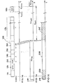
- Fig. 1 is a packet 100, as it is transmitted in a radio network, shown schematically.
- the package 100 has a frame with the fields 140, 150, 160 and 170.
- the transmission of packet 100 is shown over time t. (Engl. Preamble)
- a preamble 110 In this case, first, a preamble 110, then a start field 120 (SFD - engl S tart of F rame D elimiter.), followeded by a packet header 130 (PHR -. Engl P HY H Eade R) with the information for the frame length and subsequently transmitting a frame with fields 140, 150, 160, and 170.
- PHR -. Engl P HY H Eade R the information for the frame length and subsequently transmitting a frame with fields 140, 150, 160, and 170.
- the representation in Fig. 1a is exemplary of a packet 100 with a data frame of the industry standard IEEE 802.15.4.
- the data frame comprises a frame control field 140, a sequence number 150, an address field 160, and further fields 170 of payload data having a number of n octets.
- the payload data is usually the overwhelming extent of the data frame.
- the packet 100 is required to contain an address 160.
- Address 160 contains a first component that allows for association with the network. For this purpose, for example, the first component of the address 160 with a network identifier NWID stored in the node (FIG. Fig. 3 ) compared.
- Address 160 contains a second component that allows for association with exactly one node. For this purpose, for example, the second component of the address 160 of the packet 100 with a node identifier KNID stored in the node (FIG. Fig. 3 ) compared.
- the network identifier NWID and the node identifier KNID form a unique identification by means of which exactly one node in the radio network can be identified.
- the industry standard IEEE 802.15.4. further defines packets with a beacon frame, an acknowledgment frame, and a MAC command frame. Part of the defined framework requires of one Receiver an acknowledgment 180 (ACK nowledgement) of receipt.
- the confirmation 180 will, as in Fig. 1a represented between the times tACKa and tACKb returned by the receiver of the frame to the transmitter.
- Other packages of other industry standards such as WLAN, Bluetooth or WiMax may have a different structure, for example with a different order of the fields, but are also defined with an address.
- a receiver circuit 310 as this in Fig. 3 is shown activated in the as in Fig. 1b illustrated a control signal en by means of a high level, the receiver circuit 310 turns on. A receiving status of a receiving node is thereby controlled in an on state RXON.
- a search phase 210 begins, as described in FIG Fig. 1c is shown, wherein the receiver circuit tries to synchronize to a received signal.
- the receiving circuit Upon receiving the preamble 110 of the packet 100, the receiving circuit performs a free cross estimation. Synchronization parameters, such as phase, timing or offset are determined. For further reception, the synchronization parameters are frozen.
- the preamble sequence 110 and the subsequent start field 120 (SFD -. Engl S tart of F rame elimiter D) make it possible to perform the receiving node symbol synchronization.
- the synchronized state defines a transmission phase 230 in which the fields 130, 140, 150 and 160 are received. The length of the following frame (140, 150, 160, 170) is determined from the packet header 130.
- the address 160 contained in the packet 100 is determined. On the basis of the address 160, a case distinction is made by the receiving node.
- reception of the current packet 100 is continued by the receiving circuit 310 if the determined address 160 matches the network identifier NWID of the node and the node identifier KNID of the node.
- the packet is intended for the receiving node itself, so that the fields 170 are received with the user data from the node and possibly evaluated.
- an arithmetic unit 360 (FIG. Fig. 3 ), such as a microcontroller woken up.
- the receiving circuit 310 is controlled.
- the reception circuit 310 for stopping the reception of the current packet 100 is turned off during the further transmission of the packet 100.
- a receiving state of the receiving node changes from an on state RXON to an off state RXOFF.
- Illustrated by way of example is a control signal en, which switches off the receiver circuit 310 of the node through a low level as a function of the determined address 160 during the transmission of the packet 100.
- a receiving status of the receiving node is thereby controlled in an off state RXOFF.
- An off period tOFF in which the receiving circuit 310 is turned off, may be provided as a fixed value, for example.
- the switch-off duration tOFF is preferably selected by an evaluation circuit 330 (FIG. Fig. 3 ).
- the calculation of the switch-off duration tOFF is based on the frame length defined in the packet header 130.
- the calculation of the switch-off duration tOFF is carried out optionally, but preferably based on the transmission rate, if this can be changed in the radio network.
- the calculation of the switch-off duration tOFF is carried out optionally, but preferably on the basis of information contained in the frame as to whether an acknowledgment 180 is to be returned by the receiver.
- the significant advantage is achieved that during the off period tOFF, the current consumption by the receiving circuit 310 is substantially reduced. Since the length of the fields 170 in the package 100 far outweighs the average power consumption can be significantly reduced, so that a battery life of a node, which is operated with a battery is increased.
- the timing of the transmission timing of the acknowledgment 180 to the end of the packet 100 is set at the system level. Therefore, if the off period tOFF is calculated at a time tACKe to the end of the confirmation 180, the power consumption can be further reduced.
- a reaction takes place which in Fig. 1c is shown.
- synchronization parameters - such as phase, timing or frequency offset - of the receive circuit 310 are cleared during the transmission of the packet 100, causing the packet 100 to be aborted.
- the search phase 210 is restarted.
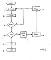
- Fig. 2 is a schematic flow diagram for a case decision shown schematically.
- step 1 synchronization parameters for the reception are reset (R-SYNC).
- step 2 a synchronization 220, SYNC to a received preamble 110 and the reception of a start field 120, a packet header 130 and possibly other fields 140, 150, and an address 160.
- a component of the address 160 is in step 3 with a Network ID NWID compared. If address 160 and network identifier NWID do not match, the synchronization parameters are cleared again in step 1.
- a component of the address 160 is compared with a node identifier KNID in step 4. If the address 160 and the node identifier KNID do not match, a switch-off duration tOFF is calculated in step 7, a timer with the switch-off duration is started, and a receive circuit 310 (FIG. Fig. 3 ) is set in an off state RXOFF in step 8. In the off state, the majority of the circuit of the node is turned off. It is only necessary to power the timer. After the timer has elapsed, the receiving circuit 310 is set to a switch-on state RXON in step 9, and in step 1 the synchronization parameters are cleared again.
- the packet 100 is destined for the node itself and the node receives the packet 100 in step 5. If the frame sent with the packet 100 requires acknowledgment, the acknowledgment ACK is returned in step 6 Posted.
- FIG Fig. 3 A schematic block diagram of a circuit 300 of a node of a radio network is shown in FIG Fig. 3 shown.
- a network identifier NWID is stored, which is common to all nodes of the same radio network.
- a node identifier is stored in the circuit 300, which allows for the node individual identification in the radio network.
- the circuit has a receiving circuit 310 for receiving a current packet 100.
- the receiving circuit 310 is connected to an antenna for reception.
- the receiving circuit 310 has a first control input 311 and a second control input 312 for controlling the reception. Via the first control input 311, the receiving circuit 310 can be switched on and off by means of a first control signal. Via the second control input 312, synchronization parameters can be erased by means of a second control signal r. Both control signals en and r can cause an abort of the reception of the current packet.
- the circuit further comprises an evaluation circuit 330, which is connected via a number of control outputs 351, 352 to the first control input 311 and the second control input 312 of the receiving circuit 310 for controlling the reception.
- the evaluation circuit 330 has a memory 340, for example a register REG for storing information contained in the packet 100.
- the evaluation circuit 330 is set up during the reception of the current packet 100 to determine an address 160 contained in the packet 100.
- the evaluation circuit 310 a in Fig. 3 not shown logic, in particular a state machine.
- the address is read from the memory 340, for example.
- the evaluation circuit 330 is set up for case decision. If the determined address 160 coincides with the node NWID of the node stored in the evaluation circuit 330 and the node ID KNID of the node, the receiving circuit 310 and the evaluation circuit 330 continue to receive the current packet 100. To check the match, the evaluation circuit 330 has a digital comparator 350. The evaluation circuit 330 furthermore has a connection to a computing unit 360, for example a microcontroller. In a positive comparison result, the arithmetic unit 360 is woken up.
- the arithmetic unit 360 is in this case designed for processing a program sequence of a software implemented in the arithmetic unit 360.
- the functions of the state machine in the evaluation circuit 330 can be used independently of the execution of the software in the arithmetic unit 360.
- the evaluation circuit 330 can send back an acknowledgment ACK to the sender of the packet 100 via the transmission circuit 320.
- the evaluation circuit 330 is arranged to stop receiving the current packet 100 by outputting a control signal en or r to the receiving circuit 310.
- the control of the receiving circuit 310 by the evaluation circuit 330 still takes place during the transmission of the current packet 100. Complete reception of the current packet 100 will not occur in this case.
- the invention is not limited to the illustrated embodiments of the FIGS. 1a to 3 limited.
- the functionality of the circuit according to Fig. 3 can be used particularly advantageously for a radio network according to an industry standard, such as WLAN or WiMax.
- the function is preferably used for a battery-operated node of a radio network according to the industry standard IEEE 802.15.4.
Landscapes
- Engineering & Computer Science (AREA)
- Computer Networks & Wireless Communication (AREA)
- Signal Processing (AREA)
- Mobile Radio Communication Systems (AREA)
- Small-Scale Networks (AREA)
Applications Claiming Priority (1)
| Application Number | Priority Date | Filing Date | Title |
|---|---|---|---|
| DE102009029783.9A DE102009029783B4 (de) | 2009-06-18 | 2009-06-18 | Schaltung und Verfahren zum Betrieb eines Knotens in einem Funknetz |
Publications (2)
| Publication Number | Publication Date |
|---|---|
| EP2265083A2 true EP2265083A2 (fr) | 2010-12-22 |
| EP2265083A3 EP2265083A3 (fr) | 2014-02-19 |
Family
ID=42790612
Family Applications (1)
| Application Number | Title | Priority Date | Filing Date |
|---|---|---|---|
| EP10006049.0A Withdrawn EP2265083A3 (fr) | 2009-06-18 | 2010-06-11 | Commutation et procédé de fonctionnement d'un nýud dans un réseau radio |
Country Status (3)
| Country | Link |
|---|---|
| US (2) | US8615012B2 (fr) |
| EP (1) | EP2265083A3 (fr) |
| DE (1) | DE102009029783B4 (fr) |
Families Citing this family (1)
| Publication number | Priority date | Publication date | Assignee | Title |
|---|---|---|---|---|
| DE102009029783B4 (de) | 2009-06-18 | 2016-02-04 | Atmel Corp. | Schaltung und Verfahren zum Betrieb eines Knotens in einem Funknetz |
Family Cites Families (9)
| Publication number | Priority date | Publication date | Assignee | Title |
|---|---|---|---|---|
| DE19952840A1 (de) * | 1999-11-03 | 2001-05-23 | Wincor Nixdorf Gmbh & Co Kg | Datenübertragung für zeitweise inaktive Empfänger |
| AU2002255568B8 (en) * | 2001-02-20 | 2014-01-09 | Adidas Ag | Modular personal network systems and methods |
| JP2003087172A (ja) * | 2001-09-07 | 2003-03-20 | Toshiba Corp | 情報通信装置、無線通信端末、情報通信プログラム |
| GB0228396D0 (en) * | 2002-12-05 | 2003-01-08 | Synad Technologies Ltd | Terminating frame reception |
| US7257095B2 (en) * | 2003-07-30 | 2007-08-14 | Texas Instruments Incorporated | Power saving via physical layer address filtering in WLANs |
| KR100590866B1 (ko) * | 2003-12-04 | 2006-06-19 | 삼성전자주식회사 | 무선 네트워크를 통한 액세스 포인트의 무선 단말 등록방법 및 그 장치 |
| US7406341B2 (en) * | 2005-02-25 | 2008-07-29 | Intel Corporation | Receive-aware power saving in a wireless communications device |
| US7710939B2 (en) * | 2007-02-06 | 2010-05-04 | Samsung Electronics Co., Ltd. | Method and system for power saving in wireless local area communication networks |
| DE102009029783B4 (de) | 2009-06-18 | 2016-02-04 | Atmel Corp. | Schaltung und Verfahren zum Betrieb eines Knotens in einem Funknetz |
-
2009
- 2009-06-18 DE DE102009029783.9A patent/DE102009029783B4/de active Active
-
2010
- 2010-06-11 EP EP10006049.0A patent/EP2265083A3/fr not_active Withdrawn
- 2010-06-18 US US12/818,907 patent/US8615012B2/en active Active
-
2013
- 2013-12-20 US US14/137,387 patent/US9326260B2/en active Active
Non-Patent Citations (1)
| Title |
|---|
| None |
Also Published As
| Publication number | Publication date |
|---|---|
| US8615012B2 (en) | 2013-12-24 |
| DE102009029783A1 (de) | 2010-12-23 |
| US20100322121A1 (en) | 2010-12-23 |
| DE102009029783B4 (de) | 2016-02-04 |
| US9326260B2 (en) | 2016-04-26 |
| EP2265083A3 (fr) | 2014-02-19 |
| US20140105206A1 (en) | 2014-04-17 |
Similar Documents
| Publication | Publication Date | Title |
|---|---|---|
| DE69820075T2 (de) | Lokales kommunikationssystem, verfahren zum betrieb und stationen zur verwendung in diesem system | |
| DE3041134C2 (de) | Datenübertragungsanordnung zur Datenübertragung über eine Stromleitung | |
| EP2702495B1 (fr) | Procédé et dispositif de transmission de données sérielle adaptée à la capacité mémoire | |
| DE102010041223A1 (de) | Verfahren und Vorrichtung zur seriellen Datenübertragung mit umschaltbarer Datenrate | |
| DE102013214888A1 (de) | Transceiver zur seriellen Datenkommunikation mit einem PWM-codierten Signal | |
| WO2020089008A1 (fr) | Station d'abonné pour un système de bus série et procédé d'émission d'un message dans un système de bus série | |
| DE102012207883A1 (de) | Verfahren zum Übertragen von Daten mit einem Ethernet-AVB-Transportprotokoll zwischen Knoten eines Kraftfahrzeugs sowie zur Durchführung des Verfahrens eingerichtetes Steuergerät | |
| EP1675311B1 (fr) | Méthode de transfert de télégrammes de données par bus de terrain | |
| DE102009029783B4 (de) | Schaltung und Verfahren zum Betrieb eines Knotens in einem Funknetz | |
| DE102013220707A1 (de) | Verfahren zum Betreiben eines Datenbusses, entsprechender Datenbus und Fahrzeug mit einem solchen Datenbus | |
| DE102023205267A1 (de) | Sendemodul für eine Sende-/Empfangseinrichtung einer Teilnehmerstation eines seriellen Bussystems und Verfahren zum Senden einer Nachricht mit differentiellen Signalen in einem seriellen Bussystem | |
| DE102011006884A1 (de) | Verfahren und Vorrichtung zur Erhöhung der Datenübertragungskapazität in einem seriellen Bussystem | |
| WO2008012327A1 (fr) | Procédé de transmission de données sans fil entre une audioprothèse et un appareil externe | |
| EP0298575B1 (fr) | Récepteur d'appel avec distributeur de la tension d'alimentation | |
| DE202009004079U1 (de) | Galvanisch getrenntes Energie- und Datenübertragungsmodul | |
| EP0568938A1 (fr) | Méthode de production de communication radiotéléphonique antiparasite | |
| WO2023093954A1 (fr) | Procédé de transmission de messages de véhicule à x, et module de communication de véhicule à x | |
| DE102004018555B4 (de) | Verfahren zur Datenkommunikation zwischen einer Basisstation und einem Transponder, Basisstation zur Datenkommunikation sowie Datenkommunikationssystem | |
| EP2321997B1 (fr) | Procédé d'échange d'informations de routage dans un réseau de communication sans fil maillé | |
| DE102021122686A1 (de) | Verfahren zum betreiben eines netzwerks | |
| WO2021148351A1 (fr) | Dispositif d'émission/réception et dispositif de commande de communication pour un poste d'abonné d'un système de bus série, et procédé de communication dans un système de bus série | |
| EP3487184B1 (fr) | Unité émettrice de la valeur de consommation et son procédé de fonctionnement, unité réceptrice de la valeur de consommation et son procédé de fonctionnement ainsi que dispositif émetteur-récepteur et son procédé de fonctionnement | |
| DE102005014785A1 (de) | Funkbasisstation, Mobilkommunikationssystem und Funkkommunikationsverfahren | |
| DE102010052890B4 (de) | Sende-Empfangs-Vorrichtung und Verfahren zum Empfang | |
| EP2929651B1 (fr) | Procédé de réduction de l'absorption d'énergie dans des réseaux |
Legal Events
| Date | Code | Title | Description |
|---|---|---|---|
| PUAI | Public reference made under article 153(3) epc to a published international application that has entered the european phase |
Free format text: ORIGINAL CODE: 0009012 |
|
| AK | Designated contracting states |
Kind code of ref document: A2 Designated state(s): AL AT BE BG CH CY CZ DE DK EE ES FI FR GB GR HR HU IE IS IT LI LT LU LV MC MK MT NL NO PL PT RO SE SI SK SM TR |
|
| AX | Request for extension of the european patent |
Extension state: BA ME RS |
|
| RAP1 | Party data changed (applicant data changed or rights of an application transferred) |
Owner name: ATMEL CORPORATION |
|
| PUAL | Search report despatched |
Free format text: ORIGINAL CODE: 0009013 |
|
| AK | Designated contracting states |
Kind code of ref document: A3 Designated state(s): AL AT BE BG CH CY CZ DE DK EE ES FI FR GB GR HR HU IE IS IT LI LT LU LV MC MK MT NL NO PL PT RO SE SI SK SM TR |
|
| AX | Request for extension of the european patent |
Extension state: BA ME RS |
|
| RIC1 | Information provided on ipc code assigned before grant |
Ipc: H04W 52/02 20090101AFI20140114BHEP |
|
| STAA | Information on the status of an ep patent application or granted ep patent |
Free format text: STATUS: THE APPLICATION IS DEEMED TO BE WITHDRAWN |
|
| 18D | Application deemed to be withdrawn |
Effective date: 20140102 |