EP2264848A1 - Cable connection - Google Patents
Cable connection Download PDFInfo
- Publication number
- EP2264848A1 EP2264848A1 EP09162864A EP09162864A EP2264848A1 EP 2264848 A1 EP2264848 A1 EP 2264848A1 EP 09162864 A EP09162864 A EP 09162864A EP 09162864 A EP09162864 A EP 09162864A EP 2264848 A1 EP2264848 A1 EP 2264848A1
- Authority
- EP
- European Patent Office
- Prior art keywords
- cable
- screw
- cable gland
- gland according
- einsteckstutzen
- Prior art date
- Legal status (The legal status is an assumption and is not a legal conclusion. Google has not performed a legal analysis and makes no representation as to the accuracy of the status listed.)
- Granted
Links
Images


Classifications
-
- H—ELECTRICITY
- H02—GENERATION; CONVERSION OR DISTRIBUTION OF ELECTRIC POWER
- H02G—INSTALLATION OF ELECTRIC CABLES OR LINES, OR OF COMBINED OPTICAL AND ELECTRIC CABLES OR LINES
- H02G3/00—Installations of electric cables or lines or protective tubing therefor in or on buildings, equivalent structures or vehicles
- H02G3/02—Details
- H02G3/06—Joints for connecting lengths of protective tubing or channels, to each other or to casings, e.g. to distribution boxes; Ensuring electrical continuity in the joint
- H02G3/0616—Joints for connecting tubing to casing
- H02G3/0625—Joints for connecting tubing to casing with means for preventing disengagement of conductors
- H02G3/0633—Joints for connecting tubing to casing with means for preventing disengagement of conductors with means urging the conductors to follow a non-straight line
-
- H—ELECTRICITY
- H02—GENERATION; CONVERSION OR DISTRIBUTION OF ELECTRIC POWER
- H02G—INSTALLATION OF ELECTRIC CABLES OR LINES, OR OF COMBINED OPTICAL AND ELECTRIC CABLES OR LINES
- H02G3/00—Installations of electric cables or lines or protective tubing therefor in or on buildings, equivalent structures or vehicles
- H02G3/02—Details
- H02G3/06—Joints for connecting lengths of protective tubing or channels, to each other or to casings, e.g. to distribution boxes; Ensuring electrical continuity in the joint
- H02G3/0616—Joints for connecting tubing to casing
- H02G3/0625—Joints for connecting tubing to casing with means for preventing disengagement of conductors
- H02G3/0675—Joints for connecting tubing to casing with means for preventing disengagement of conductors with bolts operating in a direction parallel to the conductors
-
- H—ELECTRICITY
- H02—GENERATION; CONVERSION OR DISTRIBUTION OF ELECTRIC POWER
- H02G—INSTALLATION OF ELECTRIC CABLES OR LINES, OR OF COMBINED OPTICAL AND ELECTRIC CABLES OR LINES
- H02G3/00—Installations of electric cables or lines or protective tubing therefor in or on buildings, equivalent structures or vehicles
- H02G3/02—Details
- H02G3/06—Joints for connecting lengths of protective tubing or channels, to each other or to casings, e.g. to distribution boxes; Ensuring electrical continuity in the joint
- H02G3/0616—Joints for connecting tubing to casing
- H02G3/0691—Fixing tubing to casing by auxiliary means co-operating with indentations of the tubing, e.g. with tubing-convolutions
-
- H—ELECTRICITY
- H02—GENERATION; CONVERSION OR DISTRIBUTION OF ELECTRIC POWER
- H02K—DYNAMO-ELECTRIC MACHINES
- H02K5/00—Casings; Enclosures; Supports
- H02K5/04—Casings or enclosures characterised by the shape, form or construction thereof
- H02K5/22—Auxiliary parts of casings not covered by groups H02K5/06-H02K5/20, e.g. shaped to form connection boxes or terminal boxes
- H02K5/225—Terminal boxes or connection arrangements
-
- H—ELECTRICITY
- H02—GENERATION; CONVERSION OR DISTRIBUTION OF ELECTRIC POWER
- H02K—DYNAMO-ELECTRIC MACHINES
- H02K7/00—Arrangements for handling mechanical energy structurally associated with dynamo-electric machines, e.g. structural association with mechanical driving motors or auxiliary dynamo-electric machines
- H02K7/14—Structural association with mechanical loads, e.g. with hand-held machine tools or fans
-
- H—ELECTRICITY
- H02—GENERATION; CONVERSION OR DISTRIBUTION OF ELECTRIC POWER
- H02G—INSTALLATION OF ELECTRIC CABLES OR LINES, OR OF COMBINED OPTICAL AND ELECTRIC CABLES OR LINES
- H02G3/00—Installations of electric cables or lines or protective tubing therefor in or on buildings, equivalent structures or vehicles
- H02G3/22—Installations of cables or lines through walls, floors or ceilings, e.g. into buildings
Definitions
- the invention relates to a cable gland for an electronics housing of an electric motor having a through opening, consisting of a cable adapter and a screw-on for attaching a cable connection to a housing, for example for attaching a cable harness to an electronics housing of an electric motor.
- the invention also includes an electronics housing of an electric motor with such a cable gland.
- Such a cable gland is already out of the document DE 9406382 U1 known.
- this cable gland two mutually rotatable parts, a cable adapter and a screw, are fixed by snap or snap connections axially and by a locking device in a predetermined rotational position.
- a disadvantage of this design is that the rotational position is predetermined by the latching device.
- a second disadvantage is that the cable gland must be twisted for fixation.
- the assembly can be hampered by these disadvantages.
- such an embodiment with a latching connection is difficult to solve and can be damaged during the release.
- the length of the housing-side part is extended by a mounted on the outer circumference hexagon, which serves as a tool engagement for screwing the Anschraubstutzens to the housing, which may also adversely affect the installation due to space.
- the electronics housing has an opening for electrical connection, said opening being sealed with a connection connector connected to external connection lines.
- the present invention has for its object to avoid the disadvantages described above and to design a cable gland of the type described above such that there is no restriction in the rotatability, the fixation of the cable gland is possible at any rotational position, the connection is easy and without damage solvable and at the same time the length of the cable gland is kept small.
- this is achieved by arranged on the cable adapter and the screw fixing, which allow in a mounting position, an axial insertion of the cable adapter in the screw with any rotational position relative to each other and any alignment of the rotational position of the cable adapter relative to the screw in an inserted state and in a fixing position the cable adapter axially and in the respective rotational position with the mounting boss determine.
- the cable adapter for the mounting position has a Einsteckstutzen having a running on its outer circumference snap recess and the screw on the side of its insertion a plurality of circumferentially distributed radially elastic Schnapparme has as fixing, which in the fully inserted state of the Einsteckstutzens in engage the snap recess and cause axial Kraftform gleichIST between the spigot and the snap arms.
- This has the advantage that the cable adapter can be inserted with any rotational position in the mounting boss and the rotational position is arbitrarily aligned even after insertion.
- a union nut for the fixing position is designed as an additional fixing means which is pushed onto the Einsteckstutzen and which is screwed with a screwing behind the snap arms lying clamping thread of the screw and by means of an inner, against the screwing direction tapered clamping surface of the Union nut, an axial and acting against rotation frictional connection between the spigot and the snap arms of the screw causes.
- This fixation has the further advantage that it is based on an easy-to-release frictional connection between the union nut, the clamping arms of the mounting boss and the clamping recess of the Einsteckstutzens and thus can be solved without damaging the Schnapparme or Schnappverianaung.
- the present invention has the advantage of allowing a shortening of the Anschraubstutzens that the mounting boss is provided on its inner circumference of the through hole in the Anschraubgewindes with an inner polygonal contour as mecanickraftangriff, which allows the mounting boss with a normal hex wrench from the inside screwed.
- the cable gland invention is advantageously made of plastic.
- FIG. 1 and Fig. 2 an example cable gland according to the invention is exemplified, which consists of a cable adapter 1, a screw 2, a union nut 3, a screw plug 4 and a plurality of O-ring seals 1.5, 2.4, 4.1.
- the screw-2 is hollow cylinder-shaped and has two divided by a running on the outer periphery of the bearing wall 2.5 housing sections with a through hole.
- the screwed connection 2 has a screw thread 2.1 on its outer circumference and a circumferential groove 2.3 with an O-ring seal 2.4 between the screw thread 2.1 and the bearing wall 2.5.
- the O-ring seal 2.4 seals the connection between the mounting boss 2 and a mounting housing, not shown.
- an internal polygonal contour 2.2 located on the inner circumference of the passage opening in the region of Anschraubgewindes 2.1 an internal polygonal contour 2.2, which serves as an internal force attack for screwing the Anschraubstutzens 2 in the mounting housing by means of a polygonal key.
- the mounting stud 2 has a plurality of radially elastic snap arms 2.8 distributed on its outer circumference, which are formed as circumferential segments separated by a gap and taper towards the insertion opening 2.6 and have bevels 2.9 on their inner and outer sides , Between the snap arms 2.8 and the bearing wall 2.5 of the screw 2 is located on the outer circumference of a clamping thread 2.7. In addition, located at the inner end of the insertion opening 2.6 extending over the inner circumference centering 2.10, which centers the cable adapter 1 in the fully inserted state in the insertion opening 2.6.
- the cable adapter 1 is also hollow cylindrical in shape and has two by a running on the outer circumference hexagon 1.8 split housing sections with a through hole.
- the cable adapter 1 has a Einsteckstutzen 1.1.
- the Einsteckstutzen 1.1 has facing at its the screw 2 End a conically tapered chamfer 1.12 the circumference and on its end face a centering attachment 1.7.
- the insertion piece 1.1 has a snap recess 1.2 extending on its outer circumference and has a circumferential groove 1.4 with an O-ring seal 1.5 between the snap recess 1.2 and the chamfer 1.12.
- the O-ring seal 1.5 seals the connection between the mounting boss 2 and the cable adapter 1.
- the cable adapter 1 has a cable receiving socket 1.13.
- the cable receiving socket 1.13 has at its end remote from the screw 2 a cable connection opening 1.9 with a running in its inner circumference internal thread 1.10 and at its outer periphery a plurality of circumferentially distributed axially extending attack recesses 1.11.
- the axes of the Einsteckstutzens 1.1 and the cable receiving socket 1.13 include an angle ⁇ ⁇ 180 °, preferably an obtuse angle.
- the union nut 3 has on the side facing the mounting stud 2 side extending in the inner circumference clamping thread 3.1 and a running on its outer circumference hexagon 3.3. At the side facing away from the screw 2 side of the inner circumference is a tapered clamping surface 3.2.
- the hexagon socket 3.3 serves as a force attack for a not shown clamping tool to unscrew the union nut 3 by means of its clamping thread 3.1 on the clamping thread 2.7 of the screw 2.
- the assembly of in Fig. 1 and 2 illustrated cable gland according to the invention is carried out according to Fig. 4 on an electronics housing 6 z. B. an unspecified electric motor.
- the electronics housing 6 has at least one Anschraubö réelle 6.1 provided with an internal thread, in which the mounting boss 2 is screwed. To seal the screw 2, the previously mentioned O-ring seal 2.4 is used. As a result, the mounting boss is fixed to the electronics housing 6.
- the cable gland can now be fixed in any rotational position of the cable adapter 1 relative to the screw 2 by the union nut 3 is pushed over the cam 1.3 of the Einsteckstutzens 1.1 and screwed onto the clamping thread 2.7 of the screw 2.
- the clamping surface 3.2 of the union nut 3 exerts a radial clamping force on the snap arms 2.8 of the screw 2 and generates a frictional connection between the snap arms 2.8 of the screw 2 and the snap recess 1.2 of the Einsteckstutzens 1.1 of the cable adapter 1.
- the sealing of this junction is by the O Ring seal 1.5 ensured.
- the union nut 3 is unscrewed from the clamping screw 2.7 of the screw 2 and thus repealed the clamping force described above.
- the force-fitting connection of the snap arms 2.8 described above with the snap recess 1.2 can be easily separated without damage and without special release tools by an axial pulling out of the cable adapter 1, since the snap arms 2.8 have no undercuts.
- the screw plug 4 has an O-ring seal 4.1 attached to its thread and serves to close and seal off the cable connection opening 1.9, in that the Screw plug 4 into the internal thread of the cable connection opening 1.9, if no cable connection is required for the cable gland.
- FIG. 3 is an example of a part of a further embodiment of a cable gland according to the invention illustrated and shows a representation in which the cable connection opening 1.9 of the cable adapter 1, a corrugated pipe 5 is inserted and connected by means of an adhesive connection firmly with the internal thread 1.10 of the cable connection opening 1.9.
- the actual cable making the electrical connections is not shown.
- This prefabricated cable connection can be inserted in an arbitrary rotational position in a preassembled to a mounting screw 2 and screwed by means of the union nut 3 and the snap arms 2.8 of the screw 2 and the snap-in 1.2 of the cable adapter 1 in the respective rotational position without an additional twisting due to the cable gland invention prefabricated cable connection to be fixed.
- Fig. 5 is a section of an electronics housing 6 shown with two cable glands according to the invention.
- the electronics housing 6 has three Einschraubö réelleen 6.1 for securing a cable gland, wherein in two of these screw-6.1 a cable gland according to the invention is screwed with mounted locking screws 4 and in the third middle screw 6.1 another cable gland is attached.
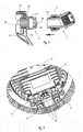
- a ventilation unit 7 with fan 7.1, guard 7.2 and electric motor is shown.
- the electric motor has an electronics housing 6 with two cable glands according to the invention, which are connected to two connecting lines 7.3.
- Fig. 7 is exemplified as a cable gland according to the invention with attached corrugated pipe 5 and not shown connecting line 7.3 is screwed into an inventive electronics housing 6.
- the electronics housing 6 has a screw-6.1 with a circular cylindrical inner sealing surface 6.2 for sealing the connection between the screw 2, cable gland and electronics housing 6 and an internal thread 6.3 for screwing the cable gland with the screw 2.1.
- the internal thread 6.3 is located relative to the sealing surface 6.2 on the inner side of the electronics housing 6.
- the invention is not limited to the illustrated and described embodiments, but also includes all the same in the context of the invention embodiments. Furthermore, the invention has hitherto not been limited to the combination of features defined in the respective independent claim, but may also be defined by any other combination of specific features of all individual features disclosed overall. This means that in principle virtually every individual feature of the respective independent claim can be omitted or replaced by at least one individual feature disclosed elsewhere in the application. In this respect, the claims are to be understood merely as a first formulation attempt for the respective invention.
Abstract
Description
Gegenstand der Erfindung ist eine Kabelverschraubung für ein Elektronikgehäuse eines Elektromotors mit einer Durchgangsöffnung, bestehend aus einem Kabeladapter und einem Anschraubstutzen zum Befestigen einer Kabelverbindung an einem Gehäuse, beispielsweise zum Befestigen eines Kabelbaums an einem Elektronikgehäuse eines Elektromotors. Die Erfindung beinhaltet ebenfalls ein Elektronikgehäuse eines Elektromotors mit einer solchen Kabelverschraubung.The invention relates to a cable gland for an electronics housing of an electric motor having a through opening, consisting of a cable adapter and a screw-on for attaching a cable connection to a housing, for example for attaching a cable harness to an electronics housing of an electric motor. The invention also includes an electronics housing of an electric motor with such a cable gland.
Eine derartige Kabelverschraubung ist bereits aus der Druckschrift
Bei einem bekannten Elektronikgehäuse eines Elektromotors wie z. B. in der
Der vorliegenden Erfindung liegt die Aufgabe zugrunde, die oben beschriebenen Nachteile zu vermeiden und eine Kabelverschraubung der eingangs beschriebenen Art derart auszugestalten, dass keine Beschränkung in der Verdrehbarkeit vorhanden ist, die Fixierung der Kabelverschraubung bei jeder beliebigen Drehlage möglich ist, die Verbindung einfach und ohne Beschädigung lösbar ist und gleichzeitig die Länge der Kabelverschraubung klein gehalten wird.The present invention has for its object to avoid the disadvantages described above and to design a cable gland of the type described above such that there is no restriction in the rotatability, the fixation of the cable gland is possible at any rotational position, the connection is easy and without damage solvable and at the same time the length of the cable gland is kept small.
Erfindungsgemäß wird dies durch an dem Kabeladapter und dem Anschraubstutzen angeordnete Fixiermittel erreicht, welche in einer Montagestellung ein axiales Einstecken des Kabeladapters in den Anschraubstutzen mit einer beliebigen Drehstellung relativ zueinander und ein beliebiges Ausrichten der Drehstellung des Kabeladapters relativ zum Anschraubstutzen in einem eingesteckten Zustand ermöglichen und in einer Fixierstellung den Kabeladapter axial und in der jeweiligen Drehstellung mit dem Anschraubstutzen feststellen.According to the invention this is achieved by arranged on the cable adapter and the screw fixing, which allow in a mounting position, an axial insertion of the cable adapter in the screw with any rotational position relative to each other and any alignment of the rotational position of the cable adapter relative to the screw in an inserted state and in a fixing position the cable adapter axially and in the respective rotational position with the mounting boss determine.
Dabei ist es vorteilhaft, dass der Kabeladapter für die Montagestellung einen Einsteckstutzen aufweist, der eine auf seinem Außenumfang verlaufende Schnappvertiefung besitzt und der Anschraubstutzen an der Seite seiner Einstecköffnung mehrere an deren Umfang verteilte radialelastische Schnapparme als Fixiermittel aufweist, welche im vollständig eingesteckten Zustand des Einsteckstutzens in die Schnappvertiefung eingreifen und eine axiale Kraftformschlussverbindung zwischen dem Einsteckstutzen und den Schnapparmen bewirken. Dies hat den Vorteil, dass der Kabeladapter mit jeder beliebigen Drehstellung in den Anschraubstutzen eingesteckt werden kann und die Drehstellung auch nach dem Einstecken beliebig ausrichtbar ist.It is advantageous that the cable adapter for the mounting position has a Einsteckstutzen having a running on its outer circumference snap recess and the screw on the side of its insertion a plurality of circumferentially distributed radially elastic Schnapparme has as fixing, which in the fully inserted state of the Einsteckstutzens in engage the snap recess and cause axial Kraftformschlussverbindung between the spigot and the snap arms. This has the advantage that the cable adapter can be inserted with any rotational position in the mounting boss and the rotational position is arbitrarily aligned even after insertion.
Weiterhin ist es vorteilhaft, dass eine Überwurfmutter für die Fixierstellung als zusätzliches Fixiermittel ausgebildet ist, welche auf den Einsteckstutzen aufgeschoben ist und die mit einem in Aufschraubrichtung hinter den Schnapparmen liegenden Spanngewinde des Anschraubstutzens verschraubt wird und mittels einer innenliegenden, gegen die Aufschraubrichtung konisch zulaufenden Spannfläche der Überwurfmutter, eine axiale und eine gegen Verdrehung wirkende Kraftschlussverbindung zwischen dem Einsteckstutzen und den Schnapparmen des Anschraubstutzens bewirkt. Dies hat den Vorteil, dass der Kabeladapter ohne zusätzliches Verdrehen in beliebiger Drehstellung fixiert werden kann. Diese Fixierung hat den weiteren Vorteil, dass sie auf eine einfach zu lösende Kraftschlussverbindung zwischen der Überwurfmutter, den Spannarmen des Anschraubstutzen und der Spannvertiefung des Einsteckstutzens beruht und damit auch ohne Beschädigung der Schnapparme oder der Schnappvertiefung lösbar ist.Furthermore, it is advantageous that a union nut for the fixing position is designed as an additional fixing means which is pushed onto the Einsteckstutzen and which is screwed with a screwing behind the snap arms lying clamping thread of the screw and by means of an inner, against the screwing direction tapered clamping surface of the Union nut, an axial and acting against rotation frictional connection between the spigot and the snap arms of the screw causes. This has the advantage that the cable adapter can be fixed in any rotational position without additional twisting. This fixation has the further advantage that it is based on an easy-to-release frictional connection between the union nut, the clamping arms of the mounting boss and the clamping recess of the Einsteckstutzens and thus can be solved without damaging the Schnapparme or Schnappvertiefung.
Ferner hat die vorliegende Erfindung den Vorteil, dadurch eine Verkürzung des Anschraubstutzens zu ermöglichen, dass der Anschraubstutzen auf seinem Innenumfang der Durchgangsöffnung im Bereich des Anschraubgewindes mit einer innenliegenden Mehrkantkontur als Innenkraftangriff versehen ist, der es erlaubt, den Anschraubstutzen mit einem normalen Sechskantschlüssel von innen greifend einzuschrauben.Furthermore, the present invention has the advantage of allowing a shortening of the Anschraubstutzens that the mounting boss is provided on its inner circumference of the through hole in the Anschraubgewindes with an inner polygonal contour as Innenkraftangriff, which allows the mounting boss with a normal hex wrench from the inside screwed.
Die erfindungsgemäße Kabelverschraubung ist vorteilhafterweise aus Kunststoff hergestellt.The cable gland invention is advantageously made of plastic.
Weitere vorteilhafte Ausgestaltungsmerkmale der Erfindung sind in den abhängigen Ansprüchen und der nachfolgenden Beschreibung enthalten.Further advantageous features of the invention are contained in the dependent claims and the description below.
Anhand der in den beiliegenden Zeichnungen veranschaulichten Ausführungsbeispiele soll die Erfindung genauer erläutert werden. Dabei zeigen:
- Fig. 1
- eine Explosionsdarstellung eines Ausführungsbeispiels einer erfindungsgemäßen Kabelverschraubung,
- Fig. 2
- einen axialen Querschnitt eines Ausführungsbeispiels einer zusammen- gesteckten und fixierten erfindungsgemäßen Kabelverschraubung,
- Fig. 3
- einen axialen Querschnitt eines weiteren Ausführungsbeispiels einer erfindungsgemäßen Kabelverschraubung,
- Fig. 4
- einen axialen Querschnitt eines Teilbereiches eines Elektronikgehäuses mit montiertem Anschraubstutzen,
- Fig. 5
- einen Ausschnitt einer dreidimensionalen Ansicht eines Elektromotors mit Elektronikgehäuse mit erfindungsgemäßer Kabelverschraubung ohne Anschlussleitungen,
- Fig. 6
- eine dreidimensionale Ansicht einer Lüftungseinheit mit Elektromotor mit Elektronikgehäuse mit erfindungsgemäßer Kabelverschraubung gemäß Ausführungsbeispiel
Fig. 3 , - Fig. 7
- einen Querschnitt eines Ausschnitts eines Elektronikgehäuses mit eingeschraubter erfindungsgemäßen Kabelverschraubung.
- Fig. 1
- an exploded view of an embodiment of a cable gland according to the invention,
- Fig. 2
- an axial cross section of an embodiment of a mated and fixed cable gland according to the invention,
- Fig. 3
- an axial cross section of another embodiment of a cable gland according to the invention,
- Fig. 4
- an axial cross section of a portion of an electronics housing with mounted mounting boss,
- Fig. 5
- a detail of a three-dimensional view of an electric motor with electronics housing with inventive cable gland without connecting cables,
- Fig. 6
- a three-dimensional view of a ventilation unit with electric motor with electronics housing with inventive cable gland according to the embodiment
Fig. 3 . - Fig. 7
- a cross section of a section of an electronics housing with screwed in accordance with the invention gland.
In den
In
Der Anschraubstutzen 2 ist hohlzylinderförmig ausgebildet und hat zwei durch eine auf dem Außenumfang verlaufende Anlagewand 2.5 aufgeteilte Gehäuseabschnitte mit einer Durchgangsöffnung. In dem dem Kabeladapter 1 abgewandten Gehäuseabschnitt weist der Anschraubstutzen 2 auf seinem Außenumfang ein Anschraubgewinde 2.1 und zwischen dem Anschraubgewinde 2.1 und der Anlagewand 2.5 eine Umfangsnut 2.3 mit einer O-Ring Dichtung 2.4 auf. Die O-Ring Dichtung 2.4 dichtet die Verbindung zwischen dem Anschraubstutzen 2 und einem nicht dargestellten Befestigungsgehäuse ab. Zusätzlich befindet sich an dem Innenumfang der Durchgangsöffnung im Bereich des Anschraubgewindes 2.1 eine innenliegende Mehrkantkontur 2.2, die als Innenkraftangriff zum Einschrauben des Anschraubstutzens 2 in das Befestigungsgehäuse mittels eines Mehrkantschlüssels dient. In dem dem Kabeladapter 1 zugewandten Gehäuseabschnitt weist der Anschraubstutzen 2 mehrere an seinem Außenumfang verteilte radialelastische Schnapparme 2.8 auf, die als durch einen Spalt getrennte Umfangssegmente ausgebildet sind und zu der Einstecköffnung 2.6 hin konisch zulaufen und am Ende auf ihren inneren und äußeren Seiten Abschrägungen 2.9 besitzen. Zwischen den Schnapparmen 2.8 und der Anlagewand 2.5 des Anschraubstutzens 2 befindet sich auf dem Außenumfang ein Spanngewinde 2.7. Zusätzlich befindet sich am inneren Ende der Einstecköffnung 2.6 eine über den Innenumfang verlaufende Zentriervertiefung 2.10, welche den Kabeladapter 1 im voll eingesteckten Zustand in der Einstecköffnung 2.6 zentriert.The screw-2 is hollow cylinder-shaped and has two divided by a running on the outer periphery of the bearing wall 2.5 housing sections with a through hole. In the housing section facing away from the
Der Kabeladapter 1 ist ebenfalls hohlzylinderförmig ausgebildet und besitzt zwei durch einen auf dem Außenumfang verlaufenden Außensechskant 1.8 aufgeteilte Gehäuseabschnitte mit einer Durchgangsöffnung. In dem dem Anschraubstutzen 2 zugewandten Gehäuseabschnitt weist der Kabeladapter 1 einen Einsteckstutzen 1.1 auf. Der Einsteckstutzen 1.1 hat an seinem dem Anschraubstutzen 2 zugewandten Ende eine konisch verlaufende Abschrägung 1.12 des Umfangs und auf seiner Stirnfläche einen Zentrieraufsatz 1.7. Zusätzlich hat der Einsteckstutzen 1.1 eine an seinem Außenumfang verlaufende Schnappvertiefung 1.2 und weist zwischen der Schnappvertiefung 1.2 und der Abschrägung 1.12 eine Umfangsnut 1.4 mit einer O-Ring Dichtung 1.5 auf. Die O-Ring Dichtung 1.5 dichtet die Verbindung zwischen dem Anschraubstutzen 2 und dem Kabeladapter 1 ab. Außerdem befinden sich zwischen der Schnappvertiefung 1.2 und dem Außensechskant 1.8 auf dem Außenumfang des Einsteckstutzens 1.1 zwei Haltenocken 1.3 mit in axialer Richtung des Einsteckstutzens 1.1 elastisch verformbaren Endbereichen, welche im nicht eingesteckten Zustand die Überwurfmutter 3 gegen ein Herunterrutschen vom Einsteckstutzen 1.1 mittels einer Kraftformschlussverbindung mit der Spannfläche 3.2 der Überwurfmutter 3 sichern. In dem dem Anschraubstutzen 2 abgewandten Gehäuseabschnitt weist der Kabeladapter 1 einen Kabelaufnahmestutzen 1.13 auf. Der Kabelaufnahmestutzen 1.13 besitzt an seinem dem Anschraubstutzen 2 abgewandten Ende eine Kabelanschlussöffnung 1.9 mit einem in seinem Innenumfang verlaufenden Innengewinde 1.10 und an seinem Außenumfang mehrere über den Umfang verteilte axial verlaufende Angriffvertiefungen 1.11. Die Achsen des Einsteckstutzens 1.1 und des Kabelaufnahmestutzens 1.13 schließen einen Winkel α ≤ 180°, vorzugsweise einen stumpfen Winkel, ein.The
Die Überwurfmutter 3 hat an der dem Anschraubstutzen 2 zugewandten Seite ein im Innenumfang verlaufendes Spanngewinde 3.1 und einen auf ihrem Außenumfang verlaufenden Außensechskant 3.3. An der von dem Anschraubstutzen 2 abgewandten Seite des Innenumfangs befindet sich eine konisch zulaufende Spannfläche 3.2. Der Außensechskant 3.3 dient als Kraftangriff für ein nicht dargestelltes Spannwerkzeug, um die Überwurfmutter 3 mittels ihres Spanngewindes 3.1 auf das Spanngewinde 2.7 des Anschraubstutzens 2 aufzuschrauben.The
Die Montage der in
Dann erfolgt die weitere Montage der erfindungsgemäßen Kabelverschraubung, indem der Kabeladapter 1 am Anschraubstutzen 2 befestigt wird. Hierzu wird die Überwurfmutter 3 mit der Seite der Spannfläche 3.2 auf den Einsteckstutzen 1.1 des Kabeladapters 1 bis hinter die Haltenocken 1.3 aufgeschoben. Der Kabeladapter 1 wird mit einer beliebig wählbaren Drehstellung relativ zum Anschraubstutzen 2 in die Einstecköffnung 2.6 des Anschraubstutzens 2 eingesteckt. Dabei werden die radialelastischen Schnapparme 2.8 des Anschraubstutzens 2 durch die axiale Bewegungskraft des Kabeladapters 1 und durch die Bewegung der Abschrägung 2.9 der Schnapparme 2.8 gegen die Abschrägung 1.12 des Einsteckstutzens 1.1 radial aufgebogen, bis die Schnapparme 2.8 bei vollständig eingestecktem Zustand in die Schnappvertiefung 1.2 des Einsteckstutzens 1.1 einschnappen und eine axiale Kraftformschlussverbindung zwischen Anschraubstutzen 2 und Kabeladapter 1 erzeugen. Im eingeschnappten Zustand ist es möglich, die Drehstellung des Kabeladapters 1 zusätzlich auszurichten, da keine Kräfte in Umfangsrichtung erzeugt werden.Then the further assembly of the cable gland according to the invention by the
Die Kabelverschraubung kann nun in jeder beliebigen Drehstellung des Kabeladapters 1 relativ zum Anschraubstutzen 2 fixiert werden, indem die Überwurfmutter 3 über die Haltenocken 1.3 des Einsteckstutzens 1.1 geschoben und auf das Spanngewinde 2.7 des Anschraubstutzen 2 geschraubt wird. Dabei übt die Spannfläche 3.2 der Überwurfmutter 3 eine radiale Klemmkraft auf die Schnapparme 2.8 des Anschraubstutzens 2 aus und erzeugt eine Kraftschlussverbindung zwischen den Schnapparmen 2.8 des Anschraubstutzens 2 und der Schnappvertiefung 1.2 des Einsteckstutzens 1.1 des Kabeladapters 1. Die Abdichtung dieser Verbindungsstelle wird durch die O-Ring-Dichtung 1.5 sichergestellt.The cable gland can now be fixed in any rotational position of the
Zum einfachen und beschädigungsfreien Lösen der Verbindung wird die Überwurfmutter 3 vom Spanngewinde 2.7 des Anschraubstutzens 2 abgeschraubt und damit die oben beschriebene Klemmkraft aufgehoben. Die oben beschriebene Kraftformschlussverbindung der Schnapparme 2.8 mit der Schnappvertiefung 1.2 kann ohne Beschädigungen und ohne spezielle Lösewerkzeuge einfach durch ein axiales Herausziehen des Kabeladapters 1 getrennt werden, da die Schnapparme 2.8 keine Hinterschneidungen besitzen.For simple and damage-free release of the connection, the
Die Verschlussschraube 4 hat eine auf ihr Gewinde aufgesteckte O-Ring Dichtung 4.1 und dient zum Verschließen und Abdichten der Kabelanschlussöffnung 1.9, indem die Verschlussschraube 4 in das Innengewinde der Kabelanschlussöffnung 1.9 eingeschraubt wird, falls kein Kabelanschluss für die Kabelverschraubung benötigt wird.The screw plug 4 has an O-ring seal 4.1 attached to its thread and serves to close and seal off the cable connection opening 1.9, in that the Screw plug 4 into the internal thread of the cable connection opening 1.9, if no cable connection is required for the cable gland.
In
In
In
In
Die Erfindung ist nicht auf die dargestellten und beschriebenen Ausführungsbeispiele beschränkt, sondern umfasst auch alle im Sinne der Erfindung gleichwirkenden Ausführungen. Ferner ist die Erfindung bislang auch noch nicht auf die in dem jeweiligen unabhängigen Anspruch definierte Merkmalskombination beschränkt, sondern kann auch durch jede beliebige andere Kombination von bestimmten Merkmalen aller insgesamt offenbarten Einzelmerkmale definiert sein. Dies bedeutet, dass grundsätzlich praktisch jedes Einzelmerkmal des jeweiligen unabhängigen Anspruchs weggelassen bzw. durch mindestens ein an anderer Stelle der Anmeldung offenbartes Einzelmerkmal ersetzt werden kann. Insofern sind die Ansprüche lediglich als ein erster Formulierungsversuch für die jeweilige Erfindung zu verstehen.The invention is not limited to the illustrated and described embodiments, but also includes all the same in the context of the invention embodiments. Furthermore, the invention has hitherto not been limited to the combination of features defined in the respective independent claim, but may also be defined by any other combination of specific features of all individual features disclosed overall. This means that in principle virtually every individual feature of the respective independent claim can be omitted or replaced by at least one individual feature disclosed elsewhere in the application. In this respect, the claims are to be understood merely as a first formulation attempt for the respective invention.
Claims (15)
dadurch gekennzeichnet, dass der Kabeladapter (1) einseitig einen Gehäuseabschnitt mit einem Kabelaufnahmestutzen (1.13) und anderseitig einen Gehäuseabschnitt mit einem Einsteckstutzen (1.1) aufweist, und die Achsen des Kabelaufnahmestutzens (1.13) und des Einsteckstutzens (1.1) einen Winkel (α ≤180° bilden.Cable gland according to claim 1,
characterized in that the cable adapter (1) on one side a housing portion with a cable receiving socket (1.13) and on the other side a housing portion with a plug (1.1), and the axes of the cable receiving socket (1.13) and the insertion (1.1) an angle (α ≤180 ° form.
dadurch gekennzeichnet, dass der Einsteckstutzen (1.1) des Kabeladapters (1) eine auf seinem Außenumfang verlaufende Schnappvertiefung (1.2) aufweist, und der Anschraubstutzen (2) an der Seite seiner Einstecköffnung (2.6) mehrere an deren Umfang verteilte radialelastische Schnapparme (2.8) als Fixiermittel aufweist, welche im vollständig eingesteckten Zustand des Einsteckstutzens (1.1) in die Schnappvertiefung (1.2) eingreifen und eine axiale Kraftformschlussverbindung zwischen dem Einsteckstutzen (1.1) und den Schnapparmen (2.8) bewirken.Cable gland according to one of claims 1 or 2,
characterized in that the Einsteckstutzen (1.1) of the cable adapter (1) has a running on its outer circumference snap recess (1.2), and the screw (2) on the side of its insertion (2.6) distributed on the circumference of several radially elastic Schnapparme (2.8) Has fixing means which engage in the fully inserted state of the Einsteckstutzens (1.1) in the snap recess (1.2) and cause an axial Kraftformschlussverbindung between the Einsteckstutzen (1.1) and the Schnapparmen (2.8).
dadurch gekennzeichnet, dass eine Überwurfmutter (3) als Fixiermittel ausgebildet ist, welche auf den Einsteckstutzen (1.1) aufgeschoben ist und die mit einem in Aufschraubrichtung hinter den Schnapparmen (2.8) liegenden Spanngewinde (2.7) des Anschraubstutzens (2) verschraubt wird und mittels einer innenliegenden, gegen die Aufschraubrichtung konisch zulaufenden Spannfläche (3.2) der Überwurfmutter (3) eine axiale und eine gegen die relative Verdrehung wirkende Kraftschlussverbindung zwischen dem Einsteckstutzen (1.1) und den Schnapparmen (2.8) des Anschraubstutzens (2) bewirkt.Cable gland according to one of claims 1 to 3,
characterized in that a union nut (3) is designed as a fixing means, which is pushed onto the Einsteckstutzen (1.1) and with a screwing in behind the Schnapparmen (2.8) lying clamping thread (2.7) of the screw (2) is screwed and by means of a internal, tapered towards the screwing Clamping surface (3.2) of the union nut (3) causes an axial and against the relative rotation acting frictional connection between the Einsteckstutzen (1.1) and the Schnapparmen (2.8) of the screw (2).
dadurch gekennzeichnet, dass der Einsteckstutzen (1.1) mindestens zwei Haltenocken (1.3) an seinem Außenumfang aufweist, welche die Überwurfmutter (3) im nicht eingesteckten Zustand des Einsteckstutzens (1.1) gegen ein Herunterrutschen vom Einsteckstutzen (1.1) durch eine Kraftformschlussverbindung mit der Spannfläche (3.2) sichern.Cable gland according to claim 4,
characterized in that the Einsteckstutzen (1.1) has at least two retaining cams (1.3) on its outer circumference, which the union nut (3) in the uninstalled state of the Einsteckstutzens (1.1) against slipping off the Einsteckstutzen (1.1) by a positive locking connection with the clamping surface ( 3.2).
dadurch gekennzeichnet, dass die Schnapparme (2.8) des Anschraubstutzens (2) als in Richtung der Einstecköffnung (2.6) konisch zulaufende, durch einen Spalt getrennte Umfangssegmente (2.8) ausgebildet sind, welche an ihrem der Einstecköffnung (2.6) zugewandten Ende des Innenumfangs und des Außenumfangs eine Abschrägung (2.9) aufweisen.Cable gland according to one of claims 1 to 5,
characterized in that the snap arms (2.8) of the screw (2) in the direction of the insertion (2.6) tapered, separated by a gap circumferential segments (2.8) are formed, which at its insertion opening (2.6) facing the end of the inner circumference and the Outside a bevel (2.9) have.
dadurch gekennzeichnet, dass der Einsteckstutzen (1.1) an seiner äußeren Seitenwand (1.6) einen Zentrieraufsatz (1.7) aufweist, und der Anschraubstutzen (2) an seiner inneren Seitenwand der Einstecköffnung (2.6) eine dazu passende Zentriervertiefung (2.10) aufweist.Cable gland according to one of claims 1 to 6,
characterized in that the Einsteckstutzen (1.1) on its outer side wall (1.6) has a centering attachment (1.7), and the screw (2) on its inner side wall of the insertion opening (2.6) has a mating centering recess (2.10).
dadurch gekennzeichnet, dass der Anschraubstutzen (2) an der der Einstecköffnung (2.6) abgewandten Seite auf seinem Außenumfang ein Anschraubgewinde (2.1) aufweist, welches in Richtung des Spanngewindes (2.7) von einer Anlagewand (2.5) begrenzt wird.Cable gland according to one of claims 1 to 7,
characterized in that the mounting boss (2) on the insertion opening (2.6) facing away on its outer circumference has a Anschraubgewinde (2.1), which in the direction of the clamping thread (2.7) by an abutment wall (2.5) is limited.
dadurch gekennzeichnet, dass der Anschraubstutzen (2) auf seinem Innenumfang der Durchgangsöffnung im Bereich des Anschraubgewindes (2.1) mit einer innenliegenden Mehrkantkontur (2.2) als Innenkraftangriff versehen ist.Cable gland according to one of claims 1 to 8,
characterized in that the mounting boss (2) is provided on its inner circumference of the passage opening in the region of the Anschraubgewindes (2.1) with an inner polygonal contour (2.2) as Innenkraftangriff.
dadurch gekennzeichnet, dass der Einsteckstutzen (1.1) zwischen der Schnappvertiefung (1.2) und der Seitenwand (1.6) eine auf seinem Außenumfang verlaufende Umfangsnut (1.4) mit einer O-Ring Dichtung (1.5) aufweist.Cable gland according to one of claims 1 to 9,
characterized in that the Einsteckstutzen (1.1) between the snap-in recess (1.2) and the side wall (1.6) has a circumferential groove extending on its outer circumference (1.4) with an O-ring seal (1.5).
dadurch gekennzeichnet, dass der Anschraubstutzen (2) zwischen dem Anschraubgewinde (2.1) und der Anlagewand (2.5) eine auf seinem Außenumfang verlaufende Umfangsnut (2.3) mit einer O-Ring Dichtung (2.4) aufweist.Cable gland according to one of claims 1 to 10,
characterized in that the mounting boss (2) between the Anschraubgewinde (2.1) and the abutment wall (2.5) has a circumferential groove extending on its outer circumference (2.3) with an O-ring seal (2.4).
gekennzeichnet durch eine Kabelanschlussöffnung (1.9), die in ihrem Innenumfang ein Innengewinde (1.10) aufweist, und eine Verschlussschraube (4) mit einer O-Ring Dichtung (4.1), welche die Kabelanschlussöffnung (1.9) des Kabeladapters (1) schließt.Cable gland according to one of claims 1 to 11,
characterized by a cable connection opening (1.9), which has an internal thread (1.10) in its inner circumference, and a closure screw (4) with an O-ring seal (4.1), which closes the cable connection opening (1.9) of the cable adapter (1).
dadurch gekennzeichnet, dass ein Wellrohr (5) mit der Kabelanschlussöffnung (1.9) mittels einer Klebeverbindung fest verbunden ist.Cable gland according to one of claims 1 to 12,
characterized in that a corrugated tube (5) with the cable connection opening (1.9) is firmly connected by means of an adhesive connection.
dadurch gekennzeichnet, dass das die Kabelverschraubung aus Kunststoff hergestellt ist.Cable gland according to one of claims 1 to 13,
characterized in that the cable gland is made of plastic.
gekennzeichnet durch eine montierte Kabelverschraubung mit den Merkmalen eines der Ansprüche 1 bis 14.Electronics housing (6) of an electric motor,
characterized by a mounted cable gland having the features of one of claims 1 to 14.
Priority Applications (2)
| Application Number | Priority Date | Filing Date | Title |
|---|---|---|---|
| EP09162864.4A EP2264848B1 (en) | 2009-06-16 | 2009-06-16 | Cable connection |
| US12/816,421 US20110147081A1 (en) | 2009-06-16 | 2010-06-16 | Cable Gland |
Applications Claiming Priority (1)
| Application Number | Priority Date | Filing Date | Title |
|---|---|---|---|
| EP09162864.4A EP2264848B1 (en) | 2009-06-16 | 2009-06-16 | Cable connection |
Publications (2)
| Publication Number | Publication Date |
|---|---|
| EP2264848A1 true EP2264848A1 (en) | 2010-12-22 |
| EP2264848B1 EP2264848B1 (en) | 2013-07-31 |
Family
ID=41353886
Family Applications (1)
| Application Number | Title | Priority Date | Filing Date |
|---|---|---|---|
| EP09162864.4A Not-in-force EP2264848B1 (en) | 2009-06-16 | 2009-06-16 | Cable connection |
Country Status (2)
| Country | Link |
|---|---|
| US (1) | US20110147081A1 (en) |
| EP (1) | EP2264848B1 (en) |
Families Citing this family (11)
| Publication number | Priority date | Publication date | Assignee | Title |
|---|---|---|---|---|
| WO2013185200A1 (en) * | 2012-06-15 | 2013-12-19 | Joao Martins Neto | Cable gland with pressure indicator |
| DE102012107406A1 (en) | 2012-08-10 | 2014-05-15 | Endress + Hauser Gmbh + Co. Kg | Connection device with shielding contact |
| US9685904B2 (en) * | 2013-10-16 | 2017-06-20 | General Electric Company | Photovoltaic system with improved DC connections and method of making same |
| ES1151408Y (en) * | 2016-01-19 | 2016-05-17 | Giko Group Telecomunicaciones S L | Cable retention and sealing device |
| US11011896B2 (en) | 2016-10-18 | 2021-05-18 | CAPE Industries, LLC | Cable gland for grounding a cable |
| US11600976B2 (en) | 2016-10-18 | 2023-03-07 | CAPE Industries, LLC | Cable gland for grounding a cable and method of use |
| CN110178273B (en) * | 2016-10-18 | 2021-04-30 | 开普工业有限责任公司 | Cable closure, method and apparatus for grounding a cable |
| DE202017106818U1 (en) * | 2017-11-09 | 2018-11-14 | Conta-Clip Verbindungstechnik Gmbh | Arrangement for a cable feedthrough |
| TWM575620U (en) * | 2018-10-25 | 2019-03-11 | 大陸商安費諾光纖技術(深圳)有限公司 | Power Adapter |
| US10951015B2 (en) * | 2018-12-14 | 2021-03-16 | Robroy Industries—Texas, LLC | Electrical conduit system having improved sealing between joints |
| US11721932B2 (en) * | 2019-07-09 | 2023-08-08 | Arris Enterprises Llc | Tool-less service cable connector and corresponding systems and methods |
Citations (10)
| Publication number | Priority date | Publication date | Assignee | Title |
|---|---|---|---|---|
| DE808136C (en) * | 1949-12-09 | 1951-07-12 | Merten Geb | Stuffing box screw nipple |
| DE3417882A1 (en) * | 1984-05-14 | 1985-11-21 | Nikko Kogyo K.K., Tokio/Tokyo | Cable holder |
| EP0448396A2 (en) * | 1990-03-23 | 1991-09-25 | THOMAS & BETTS CORPORATION | Electrical connector for liquidtight conduit |
| DE9406382U1 (en) | 1994-04-16 | 1994-06-09 | Jacob Gmbh Elektrotechnische F | Elbow cable gland |
| DE29911362U1 (en) * | 1999-06-30 | 1999-09-09 | Hummel Anton Verwaltung | Connection fitting for attaching elongated bodies |
| DE19923636A1 (en) * | 1999-05-22 | 2000-11-23 | Murrplastik Systemtechnik Gmbh | Threaded connector for protective hoses end part with annular internal shoulder near foot of springs, tubular ring seal can be introduced between shoulder and free ends of springs |
| DE10135971C1 (en) * | 2001-07-24 | 2003-04-30 | Huber & Suhner Ag Pfaeffikon | Cable kinking protection device with tension restraint has 2 cooperating screw parts screwed together for tensioning clamp shells around kinking protection sleeve |
| DE10313274A1 (en) | 2002-08-01 | 2004-02-12 | Ebm Werke Gmbh & Co. Kg | Electric motor with high IP protection |
| DE10337965B3 (en) * | 2003-08-19 | 2005-02-03 | Nexans | Electrical lead coupling element has end of electrical lead fitted with adapter and metallic housing of coupling element enclosed by insulating protection body preventing ingress of moisture |
| US7504582B1 (en) * | 2005-04-18 | 2009-03-17 | Teh-Tsung Chiu | Retaining joint for fixing cable |
Family Cites Families (10)
| Publication number | Priority date | Publication date | Assignee | Title |
|---|---|---|---|---|
| US4773280A (en) * | 1987-04-01 | 1988-09-27 | Acco Babcock Inc. | Spring clip cable support assemblies |
| GB2276688B (en) * | 1993-03-26 | 1996-03-27 | Barber Eduard & Co Ltd | Pipe connectors |
| US6079749C1 (en) * | 1996-08-08 | 2001-11-06 | Omega Flex Inc | Preassembled fitting for use with corrugated tubing |
| US5798910A (en) * | 1996-08-29 | 1998-08-25 | Caloritech Inc. | Sealable housing for electrical components |
| DE10055992C2 (en) * | 2000-04-07 | 2003-07-10 | Spinner Gmbh Elektrotech | Solderable coaxial connector |
| DE50103741D1 (en) * | 2001-01-19 | 2004-10-28 | Visteon Global Tech Inc | Shaft-hub-connection |
| US6517119B2 (en) * | 2001-03-26 | 2003-02-11 | Carrand Companies, Inc. | Hose coupling with retainer ring |
| US6616194B1 (en) * | 2001-10-22 | 2003-09-09 | Arlington Industries, Inc. | Liquid tight connector |
| TW549389U (en) * | 2002-09-10 | 2003-08-21 | Ming-Shiun Jian | Pipe coupler |
| US7394021B2 (en) * | 2006-04-20 | 2008-07-01 | Magno Jr Joey D | Rotatable liquid-tight conduit connector assembly |
-
2009
- 2009-06-16 EP EP09162864.4A patent/EP2264848B1/en not_active Not-in-force
-
2010
- 2010-06-16 US US12/816,421 patent/US20110147081A1/en not_active Abandoned
Patent Citations (10)
| Publication number | Priority date | Publication date | Assignee | Title |
|---|---|---|---|---|
| DE808136C (en) * | 1949-12-09 | 1951-07-12 | Merten Geb | Stuffing box screw nipple |
| DE3417882A1 (en) * | 1984-05-14 | 1985-11-21 | Nikko Kogyo K.K., Tokio/Tokyo | Cable holder |
| EP0448396A2 (en) * | 1990-03-23 | 1991-09-25 | THOMAS & BETTS CORPORATION | Electrical connector for liquidtight conduit |
| DE9406382U1 (en) | 1994-04-16 | 1994-06-09 | Jacob Gmbh Elektrotechnische F | Elbow cable gland |
| DE19923636A1 (en) * | 1999-05-22 | 2000-11-23 | Murrplastik Systemtechnik Gmbh | Threaded connector for protective hoses end part with annular internal shoulder near foot of springs, tubular ring seal can be introduced between shoulder and free ends of springs |
| DE29911362U1 (en) * | 1999-06-30 | 1999-09-09 | Hummel Anton Verwaltung | Connection fitting for attaching elongated bodies |
| DE10135971C1 (en) * | 2001-07-24 | 2003-04-30 | Huber & Suhner Ag Pfaeffikon | Cable kinking protection device with tension restraint has 2 cooperating screw parts screwed together for tensioning clamp shells around kinking protection sleeve |
| DE10313274A1 (en) | 2002-08-01 | 2004-02-12 | Ebm Werke Gmbh & Co. Kg | Electric motor with high IP protection |
| DE10337965B3 (en) * | 2003-08-19 | 2005-02-03 | Nexans | Electrical lead coupling element has end of electrical lead fitted with adapter and metallic housing of coupling element enclosed by insulating protection body preventing ingress of moisture |
| US7504582B1 (en) * | 2005-04-18 | 2009-03-17 | Teh-Tsung Chiu | Retaining joint for fixing cable |
Also Published As
| Publication number | Publication date |
|---|---|
| US20110147081A1 (en) | 2011-06-23 |
| EP2264848B1 (en) | 2013-07-31 |
Similar Documents
| Publication | Publication Date | Title |
|---|---|---|
| EP2264848B1 (en) | Cable connection | |
| EP2864686B1 (en) | Connecting device for media lines | |
| EP2532061B1 (en) | Electric device comprising a feedthrough of a cable through a housing wall | |
| WO2010084056A1 (en) | Fixing device for fixing a cable at a housing feed-through | |
| EP2132847A1 (en) | Cable screw connection having a counter sleeve or union nut | |
| EP2695263B1 (en) | Cable-termination device | |
| DE102013109653B4 (en) | Connector housing and method for opening its cable outlet | |
| DE202010011857U1 (en) | Plug, in particular photovoltaic plug | |
| DE102010031345A1 (en) | Tamper-proof cable entry | |
| EP1460728A1 (en) | Screwed cable gland | |
| EP3292603A1 (en) | Cable/lead insertion unit | |
| WO2018153661A1 (en) | Plug coupling with strain relief for a connecting cable | |
| DE102007017918B4 (en) | Mounting arrangement for a cable or hose fitting | |
| EP2625758B1 (en) | Cable termination device | |
| DE102009033948A1 (en) | Cable or hose coupling device comprises hollow cylindric connecting piece connected with housing, and pressure element with clamping section, where attachment section is provided for attachment of coupling in opening of wall of housing | |
| DE102011018882A1 (en) | Cable gland | |
| DE202007011452U1 (en) | Mounting arrangement for a cable or hose fitting | |
| EP2276130B1 (en) | End housing for an electric cable | |
| DE102006036097B3 (en) | Plug connector for interconnecting two electrical lines, particularly for leading electrical line from transmission area to clutch area for use with e.g. motor vehicle, has component which is connected by screw thread with housing | |
| DE102007049677A1 (en) | Electrical plug-in connector, has thread engaging element brought into engaged position to thread of plug-in part, where element is radially displaceable ball loosely arranged in window of carrier element | |
| DE102008011978A1 (en) | Screw connection for sealed line duct, has cover with outer windings, and clamping screw screwed on end of cover, where clamping screw has axial channel opening between cover and clamping screw inserting in clamping part and sealing part | |
| EP3711126B1 (en) | Elbow screw joint system | |
| DE202019101084U1 (en) | connecting device | |
| EP3404777B1 (en) | Device connection | |
| DE102012005545A1 (en) | Cable termination |
Legal Events
| Date | Code | Title | Description |
|---|---|---|---|
| PUAI | Public reference made under article 153(3) epc to a published international application that has entered the european phase |
Free format text: ORIGINAL CODE: 0009012 |
|
| AK | Designated contracting states |
Kind code of ref document: A1 Designated state(s): AT BE BG CH CY CZ DE DK EE ES FI FR GB GR HR HU IE IS IT LI LT LU LV MC MK MT NL NO PL PT RO SE SI SK TR |
|
| AX | Request for extension of the european patent |
Extension state: AL BA RS |
|
| 17P | Request for examination filed |
Effective date: 20110127 |
|
| 17Q | First examination report despatched |
Effective date: 20110310 |
|
| GRAP | Despatch of communication of intention to grant a patent |
Free format text: ORIGINAL CODE: EPIDOSNIGR1 |
|
| GRAS | Grant fee paid |
Free format text: ORIGINAL CODE: EPIDOSNIGR3 |
|
| GRAA | (expected) grant |
Free format text: ORIGINAL CODE: 0009210 |
|
| AK | Designated contracting states |
Kind code of ref document: B1 Designated state(s): AT BE BG CH CY CZ DE DK EE ES FI FR GB GR HR HU IE IS IT LI LT LU LV MC MK MT NL NO PL PT RO SE SI SK TR |
|
| REG | Reference to a national code |
Ref country code: GB Ref legal event code: FG4D Free format text: NOT ENGLISH Ref country code: CH Ref legal event code: EP |
|
| REG | Reference to a national code |
Ref country code: AT Ref legal event code: REF Ref document number: 625120 Country of ref document: AT Kind code of ref document: T Effective date: 20130815 |
|
| REG | Reference to a national code |
Ref country code: IE Ref legal event code: FG4D Free format text: LANGUAGE OF EP DOCUMENT: GERMAN |
|
| REG | Reference to a national code |
Ref country code: DE Ref legal event code: R096 Ref document number: 502009007662 Country of ref document: DE Effective date: 20130926 |
|
| REG | Reference to a national code |
Ref country code: NL Ref legal event code: T3 |
|
| REG | Reference to a national code |
Ref country code: LT Ref legal event code: MG4D |
|
| PG25 | Lapsed in a contracting state [announced via postgrant information from national office to epo] |
Ref country code: SE Free format text: LAPSE BECAUSE OF FAILURE TO SUBMIT A TRANSLATION OF THE DESCRIPTION OR TO PAY THE FEE WITHIN THE PRESCRIBED TIME-LIMIT Effective date: 20130731 Ref country code: PT Free format text: LAPSE BECAUSE OF FAILURE TO SUBMIT A TRANSLATION OF THE DESCRIPTION OR TO PAY THE FEE WITHIN THE PRESCRIBED TIME-LIMIT Effective date: 20131202 Ref country code: IS Free format text: LAPSE BECAUSE OF FAILURE TO SUBMIT A TRANSLATION OF THE DESCRIPTION OR TO PAY THE FEE WITHIN THE PRESCRIBED TIME-LIMIT Effective date: 20131130 Ref country code: CY Free format text: LAPSE BECAUSE OF FAILURE TO SUBMIT A TRANSLATION OF THE DESCRIPTION OR TO PAY THE FEE WITHIN THE PRESCRIBED TIME-LIMIT Effective date: 20130918 Ref country code: HR Free format text: LAPSE BECAUSE OF FAILURE TO SUBMIT A TRANSLATION OF THE DESCRIPTION OR TO PAY THE FEE WITHIN THE PRESCRIBED TIME-LIMIT Effective date: 20130731 Ref country code: NO Free format text: LAPSE BECAUSE OF FAILURE TO SUBMIT A TRANSLATION OF THE DESCRIPTION OR TO PAY THE FEE WITHIN THE PRESCRIBED TIME-LIMIT Effective date: 20131031 Ref country code: LT Free format text: LAPSE BECAUSE OF FAILURE TO SUBMIT A TRANSLATION OF THE DESCRIPTION OR TO PAY THE FEE WITHIN THE PRESCRIBED TIME-LIMIT Effective date: 20130731 |
|
| PG25 | Lapsed in a contracting state [announced via postgrant information from national office to epo] |
Ref country code: LV Free format text: LAPSE BECAUSE OF FAILURE TO SUBMIT A TRANSLATION OF THE DESCRIPTION OR TO PAY THE FEE WITHIN THE PRESCRIBED TIME-LIMIT Effective date: 20130731 Ref country code: SI Free format text: LAPSE BECAUSE OF FAILURE TO SUBMIT A TRANSLATION OF THE DESCRIPTION OR TO PAY THE FEE WITHIN THE PRESCRIBED TIME-LIMIT Effective date: 20130731 Ref country code: PL Free format text: LAPSE BECAUSE OF FAILURE TO SUBMIT A TRANSLATION OF THE DESCRIPTION OR TO PAY THE FEE WITHIN THE PRESCRIBED TIME-LIMIT Effective date: 20130731 Ref country code: FI Free format text: LAPSE BECAUSE OF FAILURE TO SUBMIT A TRANSLATION OF THE DESCRIPTION OR TO PAY THE FEE WITHIN THE PRESCRIBED TIME-LIMIT Effective date: 20130731 Ref country code: GR Free format text: LAPSE BECAUSE OF FAILURE TO SUBMIT A TRANSLATION OF THE DESCRIPTION OR TO PAY THE FEE WITHIN THE PRESCRIBED TIME-LIMIT Effective date: 20131101 |
|
| PG25 | Lapsed in a contracting state [announced via postgrant information from national office to epo] |
Ref country code: CY Free format text: LAPSE BECAUSE OF FAILURE TO SUBMIT A TRANSLATION OF THE DESCRIPTION OR TO PAY THE FEE WITHIN THE PRESCRIBED TIME-LIMIT Effective date: 20130731 |
|
| PG25 | Lapsed in a contracting state [announced via postgrant information from national office to epo] |
Ref country code: DK Free format text: LAPSE BECAUSE OF FAILURE TO SUBMIT A TRANSLATION OF THE DESCRIPTION OR TO PAY THE FEE WITHIN THE PRESCRIBED TIME-LIMIT Effective date: 20130731 Ref country code: CZ Free format text: LAPSE BECAUSE OF FAILURE TO SUBMIT A TRANSLATION OF THE DESCRIPTION OR TO PAY THE FEE WITHIN THE PRESCRIBED TIME-LIMIT Effective date: 20130731 Ref country code: SK Free format text: LAPSE BECAUSE OF FAILURE TO SUBMIT A TRANSLATION OF THE DESCRIPTION OR TO PAY THE FEE WITHIN THE PRESCRIBED TIME-LIMIT Effective date: 20130731 Ref country code: RO Free format text: LAPSE BECAUSE OF FAILURE TO SUBMIT A TRANSLATION OF THE DESCRIPTION OR TO PAY THE FEE WITHIN THE PRESCRIBED TIME-LIMIT Effective date: 20130731 Ref country code: EE Free format text: LAPSE BECAUSE OF FAILURE TO SUBMIT A TRANSLATION OF THE DESCRIPTION OR TO PAY THE FEE WITHIN THE PRESCRIBED TIME-LIMIT Effective date: 20130731 |
|
| PG25 | Lapsed in a contracting state [announced via postgrant information from national office to epo] |
Ref country code: ES Free format text: LAPSE BECAUSE OF FAILURE TO SUBMIT A TRANSLATION OF THE DESCRIPTION OR TO PAY THE FEE WITHIN THE PRESCRIBED TIME-LIMIT Effective date: 20130731 |
|
| PLBE | No opposition filed within time limit |
Free format text: ORIGINAL CODE: 0009261 |
|
| STAA | Information on the status of an ep patent application or granted ep patent |
Free format text: STATUS: NO OPPOSITION FILED WITHIN TIME LIMIT |
|
| 26N | No opposition filed |
Effective date: 20140502 |
|
| REG | Reference to a national code |
Ref country code: DE Ref legal event code: R097 Ref document number: 502009007662 Country of ref document: DE Effective date: 20140502 |
|
| PG25 | Lapsed in a contracting state [announced via postgrant information from national office to epo] |
Ref country code: MC Free format text: LAPSE BECAUSE OF FAILURE TO SUBMIT A TRANSLATION OF THE DESCRIPTION OR TO PAY THE FEE WITHIN THE PRESCRIBED TIME-LIMIT Effective date: 20130731 Ref country code: LU Free format text: LAPSE BECAUSE OF FAILURE TO SUBMIT A TRANSLATION OF THE DESCRIPTION OR TO PAY THE FEE WITHIN THE PRESCRIBED TIME-LIMIT Effective date: 20140616 |
|
| REG | Reference to a national code |
Ref country code: CH Ref legal event code: PL |
|
| REG | Reference to a national code |
Ref country code: IE Ref legal event code: MM4A |
|
| PG25 | Lapsed in a contracting state [announced via postgrant information from national office to epo] |
Ref country code: LI Free format text: LAPSE BECAUSE OF NON-PAYMENT OF DUE FEES Effective date: 20140630 Ref country code: CH Free format text: LAPSE BECAUSE OF NON-PAYMENT OF DUE FEES Effective date: 20140630 Ref country code: IE Free format text: LAPSE BECAUSE OF NON-PAYMENT OF DUE FEES Effective date: 20140616 |
|
| REG | Reference to a national code |
Ref country code: AT Ref legal event code: MM01 Ref document number: 625120 Country of ref document: AT Kind code of ref document: T Effective date: 20140616 |
|
| REG | Reference to a national code |
Ref country code: DE Ref legal event code: R082 Ref document number: 502009007662 Country of ref document: DE Representative=s name: JOSTARNDT PATENTANWALTS-AG, DE |
|
| PG25 | Lapsed in a contracting state [announced via postgrant information from national office to epo] |
Ref country code: AT Free format text: LAPSE BECAUSE OF NON-PAYMENT OF DUE FEES Effective date: 20140616 |
|
| PG25 | Lapsed in a contracting state [announced via postgrant information from national office to epo] |
Ref country code: MT Free format text: LAPSE BECAUSE OF FAILURE TO SUBMIT A TRANSLATION OF THE DESCRIPTION OR TO PAY THE FEE WITHIN THE PRESCRIBED TIME-LIMIT Effective date: 20130731 |
|
| REG | Reference to a national code |
Ref country code: FR Ref legal event code: PLFP Year of fee payment: 8 |
|
| PG25 | Lapsed in a contracting state [announced via postgrant information from national office to epo] |
Ref country code: BG Free format text: LAPSE BECAUSE OF FAILURE TO SUBMIT A TRANSLATION OF THE DESCRIPTION OR TO PAY THE FEE WITHIN THE PRESCRIBED TIME-LIMIT Effective date: 20130731 |
|
| PG25 | Lapsed in a contracting state [announced via postgrant information from national office to epo] |
Ref country code: HU Free format text: LAPSE BECAUSE OF FAILURE TO SUBMIT A TRANSLATION OF THE DESCRIPTION OR TO PAY THE FEE WITHIN THE PRESCRIBED TIME-LIMIT; INVALID AB INITIO Effective date: 20090616 Ref country code: BE Free format text: LAPSE BECAUSE OF FAILURE TO SUBMIT A TRANSLATION OF THE DESCRIPTION OR TO PAY THE FEE WITHIN THE PRESCRIBED TIME-LIMIT Effective date: 20140630 Ref country code: TR Free format text: LAPSE BECAUSE OF FAILURE TO SUBMIT A TRANSLATION OF THE DESCRIPTION OR TO PAY THE FEE WITHIN THE PRESCRIBED TIME-LIMIT Effective date: 20130731 |
|
| REG | Reference to a national code |
Ref country code: FR Ref legal event code: PLFP Year of fee payment: 9 |
|
| REG | Reference to a national code |
Ref country code: FR Ref legal event code: PLFP Year of fee payment: 10 |
|
| PG25 | Lapsed in a contracting state [announced via postgrant information from national office to epo] |
Ref country code: MK Free format text: LAPSE BECAUSE OF FAILURE TO SUBMIT A TRANSLATION OF THE DESCRIPTION OR TO PAY THE FEE WITHIN THE PRESCRIBED TIME-LIMIT Effective date: 20130731 |
|
| PGFP | Annual fee paid to national office [announced via postgrant information from national office to epo] |
Ref country code: FR Payment date: 20200623 Year of fee payment: 12 Ref country code: DE Payment date: 20200623 Year of fee payment: 12 |
|
| PGFP | Annual fee paid to national office [announced via postgrant information from national office to epo] |
Ref country code: NL Payment date: 20200622 Year of fee payment: 12 Ref country code: GB Payment date: 20200625 Year of fee payment: 12 |
|
| PGFP | Annual fee paid to national office [announced via postgrant information from national office to epo] |
Ref country code: IT Payment date: 20200630 Year of fee payment: 12 |
|
| REG | Reference to a national code |
Ref country code: DE Ref legal event code: R119 Ref document number: 502009007662 Country of ref document: DE |
|
| REG | Reference to a national code |
Ref country code: NL Ref legal event code: MM Effective date: 20210701 |
|
| GBPC | Gb: european patent ceased through non-payment of renewal fee |
Effective date: 20210616 |
|
| PG25 | Lapsed in a contracting state [announced via postgrant information from national office to epo] |
Ref country code: GB Free format text: LAPSE BECAUSE OF NON-PAYMENT OF DUE FEES Effective date: 20210616 Ref country code: DE Free format text: LAPSE BECAUSE OF NON-PAYMENT OF DUE FEES Effective date: 20220101 |
|
| PG25 | Lapsed in a contracting state [announced via postgrant information from national office to epo] |
Ref country code: NL Free format text: LAPSE BECAUSE OF NON-PAYMENT OF DUE FEES Effective date: 20210701 Ref country code: FR Free format text: LAPSE BECAUSE OF NON-PAYMENT OF DUE FEES Effective date: 20210630 |
|
| PG25 | Lapsed in a contracting state [announced via postgrant information from national office to epo] |
Ref country code: IT Free format text: LAPSE BECAUSE OF NON-PAYMENT OF DUE FEES Effective date: 20210616 |