EP2264823A2 - Secondary battery and secondary battery manufacturing method - Google Patents
Secondary battery and secondary battery manufacturing method Download PDFInfo
- Publication number
- EP2264823A2 EP2264823A2 EP10171980A EP10171980A EP2264823A2 EP 2264823 A2 EP2264823 A2 EP 2264823A2 EP 10171980 A EP10171980 A EP 10171980A EP 10171980 A EP10171980 A EP 10171980A EP 2264823 A2 EP2264823 A2 EP 2264823A2
- Authority
- EP
- European Patent Office
- Prior art keywords
- current collecting
- collecting plate
- welding
- winding assembly
- secondary battery
- Prior art date
- Legal status (The legal status is an assumption and is not a legal conclusion. Google has not performed a legal analysis and makes no representation as to the accuracy of the status listed.)
- Withdrawn
Links
Images


Classifications
-
- H—ELECTRICITY
- H01—ELECTRIC ELEMENTS
- H01M—PROCESSES OR MEANS, e.g. BATTERIES, FOR THE DIRECT CONVERSION OF CHEMICAL ENERGY INTO ELECTRICAL ENERGY
- H01M10/00—Secondary cells; Manufacture thereof
- H01M10/04—Construction or manufacture in general
- H01M10/0431—Cells with wound or folded electrodes
-
- H—ELECTRICITY
- H01—ELECTRIC ELEMENTS
- H01M—PROCESSES OR MEANS, e.g. BATTERIES, FOR THE DIRECT CONVERSION OF CHEMICAL ENERGY INTO ELECTRICAL ENERGY
- H01M10/00—Secondary cells; Manufacture thereof
- H01M10/05—Accumulators with non-aqueous electrolyte
- H01M10/058—Construction or manufacture
- H01M10/0587—Construction or manufacture of accumulators having only wound construction elements, i.e. wound positive electrodes, wound negative electrodes and wound separators
-
- H—ELECTRICITY
- H01—ELECTRIC ELEMENTS
- H01M—PROCESSES OR MEANS, e.g. BATTERIES, FOR THE DIRECT CONVERSION OF CHEMICAL ENERGY INTO ELECTRICAL ENERGY
- H01M50/00—Constructional details or processes of manufacture of the non-active parts of electrochemical cells other than fuel cells, e.g. hybrid cells
- H01M50/50—Current conducting connections for cells or batteries
- H01M50/531—Electrode connections inside a battery casing
- H01M50/533—Electrode connections inside a battery casing characterised by the shape of the leads or tabs
-
- H—ELECTRICITY
- H01—ELECTRIC ELEMENTS
- H01M—PROCESSES OR MEANS, e.g. BATTERIES, FOR THE DIRECT CONVERSION OF CHEMICAL ENERGY INTO ELECTRICAL ENERGY
- H01M50/00—Constructional details or processes of manufacture of the non-active parts of electrochemical cells other than fuel cells, e.g. hybrid cells
- H01M50/50—Current conducting connections for cells or batteries
- H01M50/531—Electrode connections inside a battery casing
- H01M50/534—Electrode connections inside a battery casing characterised by the material of the leads or tabs
-
- H—ELECTRICITY
- H01—ELECTRIC ELEMENTS
- H01M—PROCESSES OR MEANS, e.g. BATTERIES, FOR THE DIRECT CONVERSION OF CHEMICAL ENERGY INTO ELECTRICAL ENERGY
- H01M50/00—Constructional details or processes of manufacture of the non-active parts of electrochemical cells other than fuel cells, e.g. hybrid cells
- H01M50/50—Current conducting connections for cells or batteries
- H01M50/531—Electrode connections inside a battery casing
- H01M50/536—Electrode connections inside a battery casing characterised by the method of fixing the leads to the electrodes, e.g. by welding
-
- H—ELECTRICITY
- H01—ELECTRIC ELEMENTS
- H01M—PROCESSES OR MEANS, e.g. BATTERIES, FOR THE DIRECT CONVERSION OF CHEMICAL ENERGY INTO ELECTRICAL ENERGY
- H01M50/00—Constructional details or processes of manufacture of the non-active parts of electrochemical cells other than fuel cells, e.g. hybrid cells
- H01M50/50—Current conducting connections for cells or batteries
- H01M50/531—Electrode connections inside a battery casing
- H01M50/538—Connection of several leads or tabs of wound or folded electrode stacks
-
- Y—GENERAL TAGGING OF NEW TECHNOLOGICAL DEVELOPMENTS; GENERAL TAGGING OF CROSS-SECTIONAL TECHNOLOGIES SPANNING OVER SEVERAL SECTIONS OF THE IPC; TECHNICAL SUBJECTS COVERED BY FORMER USPC CROSS-REFERENCE ART COLLECTIONS [XRACs] AND DIGESTS
- Y02—TECHNOLOGIES OR APPLICATIONS FOR MITIGATION OR ADAPTATION AGAINST CLIMATE CHANGE
- Y02E—REDUCTION OF GREENHOUSE GAS [GHG] EMISSIONS, RELATED TO ENERGY GENERATION, TRANSMISSION OR DISTRIBUTION
- Y02E60/00—Enabling technologies; Technologies with a potential or indirect contribution to GHG emissions mitigation
- Y02E60/10—Energy storage using batteries
-
- Y—GENERAL TAGGING OF NEW TECHNOLOGICAL DEVELOPMENTS; GENERAL TAGGING OF CROSS-SECTIONAL TECHNOLOGIES SPANNING OVER SEVERAL SECTIONS OF THE IPC; TECHNICAL SUBJECTS COVERED BY FORMER USPC CROSS-REFERENCE ART COLLECTIONS [XRACs] AND DIGESTS
- Y02—TECHNOLOGIES OR APPLICATIONS FOR MITIGATION OR ADAPTATION AGAINST CLIMATE CHANGE
- Y02P—CLIMATE CHANGE MITIGATION TECHNOLOGIES IN THE PRODUCTION OR PROCESSING OF GOODS
- Y02P70/00—Climate change mitigation technologies in the production process for final industrial or consumer products
- Y02P70/50—Manufacturing or production processes characterised by the final manufactured product
-
- Y—GENERAL TAGGING OF NEW TECHNOLOGICAL DEVELOPMENTS; GENERAL TAGGING OF CROSS-SECTIONAL TECHNOLOGIES SPANNING OVER SEVERAL SECTIONS OF THE IPC; TECHNICAL SUBJECTS COVERED BY FORMER USPC CROSS-REFERENCE ART COLLECTIONS [XRACs] AND DIGESTS
- Y10—TECHNICAL SUBJECTS COVERED BY FORMER USPC
- Y10T—TECHNICAL SUBJECTS COVERED BY FORMER US CLASSIFICATION
- Y10T29/00—Metal working
- Y10T29/49—Method of mechanical manufacture
- Y10T29/49002—Electrical device making
- Y10T29/49108—Electric battery cell making
- Y10T29/49114—Electric battery cell making including adhesively bonding
Landscapes
- Chemical & Material Sciences (AREA)
- Chemical Kinetics & Catalysis (AREA)
- Electrochemistry (AREA)
- General Chemical & Material Sciences (AREA)
- Engineering & Computer Science (AREA)
- Manufacturing & Machinery (AREA)
- Connection Of Batteries Or Terminals (AREA)
- Secondary Cells (AREA)
- Cell Electrode Carriers And Collectors (AREA)
Abstract
Description
- The present invention relates to a secondary battery and a. secondary battery manufacturing method., and more particularly, to a structure of a battery in which a winding assembly formed by winding a positive electrode and a. negative electrode with a separator interposed therebetween is received in a battery container along with an electrolyte and in which electricity, which is charged in and discharged from the winding assembly, can be taken from positive and negative electrode terminals to an outside.
- As lithium secondary batteries used in hybrid vehicles, batteries having high power assisting ability (large current) have been required. Accordingly, in order to suppress the heat generation due to the large current, it is necessary to reduce contact resistance inside the batteries. In order to reduce the contact resistance inside the batteries, it is necessary to increase the number of welding points between a current collecting plate and a winding assembly of the batteries.
- A conventional method of welding a current collecting plate and a winding assembly to each other by melting the current collecting plate which is a flat plate and dropping the melted plate with the gravity is known (see
JP-A-2004-158394 - However, in the method disclosed in
JP-A-2004-158394 JP-A-2004-158394 - The invention is contrived to solve the above-mentioned problem. An object of the invention is to provide a secondary battery in which a current collecting plate is attached to a winding assembly by the use of a joint design enabling a weldi.ng work even when a great gap exists between the current collecting plate and the winding assembly and a manufacturing method of the secondary battery.
- In order to accomplish the above-mentioned object, according to an aspect of the invention, there is provided a secondary battery with a structure in which a winding assembly formed by winding a positive electrode and a negative electrode with a separator interposed therebetween is received in a battery container along with an electrolyte and in which electricity which is charged in and discharged from the winding assembly can be taken from positive and negative electrode terminals to an outside, wherein a positive or negative metal foil protrudes from at least one end of the winding assembly and a current collecting plate is welded to the edge of the protruding metal foil. A plurality of recessed portions are formed in the current collecting plate before the welding and the current collecting plate is connected to the metal foil by heating and melting convex portions between the recessed portions. The welded portions of the current collecting plate after the welding form concave portions on the current collecting plate. That is, by heating the convex portions, the metal (welding metal) of the portions is melted and dropped with the gravity and can be connected to the metal foil. By solidifying the welding metal., the connection between the current collecting plate and the metal foil is ensured. The weldi.ng portions of the current collecting plate are formed on the same side of the current collecting plate so as to connect two outer peripheral edges of the winding assembly.
- Further, the current collecting plate has at an outer periphery an outer peripheral bent portion which is bent toward the winding assembly. A hole is formed at a center portion of the current collecting plate by punching and an inner peripheral bent portion which is bent toward the winding assembly is formed around the hole.
- According to another aspect of the invention, there is provided a manufacturing method of a secondary battery with a structure in which a winding assembly formed by winding a positive electrode and a negative electrode with a separator interposed therebetween is received in a battery container along with an electrolyte, in which electricity which is charged in and discharged from the winding assembly can be taken from positive and negative electrode terminals to an outside, and in which a current collecting plate is welded to an edge of a positive or negative metal foil protruding from at least an end side of the winding assembly. The secondary battery manufacturing method includes: preparing a current collecting plate having a plurality of recessed portions on a surface opposite to a surface in contact with the winding assembly; and welding the metal foil and the current collecting plate to each other, by heating convex portions between the recessed portions as welding portions and melting down them with the gravity.
- Other features of the invention will become apparent from the following description and the accompanying drawings.
- According to the invention, it is possible to obtain stable welding quality even when there is a great gap between the current collecting plate and the winding assembly.
-
-
FIG. 1 is a development view illustrating a winding assembly of a secondary battery. -
FIG. 2 is a perspective view illustrating a current collecting plate and a winding assembly of a secondary battery according to a first embodiment of the invention. -
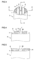
FIG. 3 is a perspective view illustrating the current collecting plate and the winding assembly of the secondary battery according to the first embodiment of the invention before they are welded to each other. -
FIG. 4 is a cross-sectional view taken along line IV-IV inFIG. 3 . -
FIG. 5 is a cross-sectional view taken along line V-V inFIG. 3 . -
FIG. 6 is a perspective view illustrating the current collecting plat.e and the winding assembly of the secondary battery according to the first embodiment of the invention after they are welded to each other. -
FIG. 7 is a. cross-sectional view taken along line VII-VII inFIG. 6 . -
FIG. 8 is a cross-sectional view taken along line VIII-VIII inFIG. 6 . -
FIG. 9 is a cross-sectional view illustrating an entire configuration of a secondary battery. -
FIG. 10 is a perspective view illustrating a current collecting plate and a winding assembly of a secondary battery according to a second embodiment of the invention after they are welded to each other. -
FIG. 11 is a perspective view illustrating a current collecting plate and a winding assembly of a secondary battery according to a third embodiment of the invention after they are welded to each other. -
FIG. 12 is a perspective view illustrating a current collecting plate and a winding assembly of a secondary battery according to a fourth embodiment of the invention before they are welded to each other. - Hereinafter, embodiments according to the invention will be described with reference to the accompanying drawings. However, the embodiments are only examples for carrying out the invention and are not intended to limit the invention. In the drawings, the same elements are denoted by the same reference numerals.
-
-
FIG. 1 is a development view illustrating a known winding assembly. InFIG. 1 , awinding assembly 5 is formed by winding plural members. In thewinding assembly 5, one member is a positive electrode foil 1 (for example, an aluminum foil with a thickness of 10 µm) of which both surfaces are coated with apositive electrode material 2 and another member is a negative electrode foil 3 (for example, a copper foil) of which both surfaces are coated with anegative electrode material 4. The foils are wound with a.separator 10 interposed therebetween to form thewinding assembly 5. Thewinding assembly 5 is put into an electrolyte to serves as a secondary battery of being charged and discharged. -
FIG. 2 is a perspective view illustrating a state of the embodiment according to the invention before acurrent collecting plate 6 is attached to thewinding assembly 5. Thepositive electrode foil 1 protrudes from the end side of thewinding assembly 5 in a wound state. In order to serve as a second.a.ry battery, it is necessary to connect. (weld) the positive current collectingplate 6 to thepositive electrode foil 1 to transmit the electricity charged in and discharged from thewinding assembly 5. -
FIG. 3 is a perspective view illustrating a state of the embodiment where thecurrent collecting plate 6 is placed on thewinding assembly 5 before they are welded to each other.FIG. 4 is a cross-sectional view taken along line IV-IV inFIG. 3 . Thecurrent collecting plate 6 according to this embodiment has a shape obtained by cutting off both end sides of a. disc and includes two welding protrusions (convex lines) 9 and four recessed portions (concave lines) 8 parallel to the line V--V (perpendicular to line IV-IV) on both sides of acenter hole 30 of the current collecting plate. The disposed positivecurrent collecting plate 6 is formed of an aluminum plate with a thickness of 1 mm and the recessedportions 8 are formed by a mechanical machining operation with, for example, a width of 1 mm and a depth of 0.5 mm. As shown inFIG. 4 , therecessed portions 8 formed in the positivecurrent collecting plate 6 are disposed in the surface opposite to the surface contacting thewinding assembly 5. Then, by applying a laser beam to thewelding protrusions 9 located between two recessedportions 8, thecurrent collecting plate 6 is welded to thepositive electrode foil 1. For example, the welding is performed by the use of a YAG laser under the welding condition of a laser power of 900 W and a welding speed of 2 m/min. - At this time, since the end face of the
positive electrode foil 1 is not even in height, the entire end of thepositive electrode foil 1 comes in contact with the positivecurrent collecting plate 6. If a laser beam is irradiated from the top surface of the flat current collecting plate without the recessedportions 8, the melted metal does not droop sufficiently due to the surface tension of the melted metal (welding metal), and thus a portion of thepositive electrode foil 1 may remain without contacting the welding metal. However, in this embodiment, since the recessedportions 8 are disposed on both sides of thewelding protrusions 9, it is possible to reduce the influence of the surface tension acting on the welding metal at the time of the application of the laser beam and the melted metal droops down enough to come in contact with the winding assembly 5 (seeFIG. 7 ). -
FIG. 5 is a cross-sectional view taken along line V-V ofFIG. 3 . As shown inFIG. 5 , the positivecurrent collecting plate 6 includes an inner peripheralbent portion 7 and an outer peripheralbent portion 11 which are formed by bending a flat plate toward the windingassembly 5. These bent portions are provided to prevent welding deformation. That is, if the positivecurrent collecting plate 6 is a simple flat plate, an angular deformation or a warp deformation may be caused by the welding. However, when the portions are bent at 90° with respect to the positivecurrent collecting plate 6 by means of the above bending process, strength enough to endure the deformation at the time of welding thecurrent collecting plate 6 is provided, thereby realizing a welding process without any welding deformation. The inner peripheralbent portion 7 is formed by extruding a flat plate which would be a current collecting plate, punching the center thereof, and then pressing the resultant structure. The outer peripheralbent portion 11 is also formed by pressing the outer periphery of the extruded structure. It is preferable to extrude and shape thecurrent collecting plate 6 that thecurrent collecting plate 6 is symmetric. -
FIG. 6 is a perspective view illustrating a welded state. As shown inFIG. 6 , the positivecurrent collecting plate 6 is welded at positions of two welding metals 12 (positions corresponding to the welding protrusions 9). In the first embodiment, since the number of contact points between the positivecurrent collecting plate 6 and the windingassembly 5 can be sufficiently secured from two welding positions, it is not necessary to enlarge the size of thecurrent collecting plate 6. Accordingly, it is possible to reduce the size of thecurrent collecting plate 6 and thus to reduce the cost for the components and materials. According to this embodiment, since the welding operation is performed along the welding positions on the same side, it is possible to reduce the number of welding operations. Therefore, it is not necessary to rotate the secondary battery during the welding operation. As a result., it is possible to simplify the welding equipment. -
FIG. 7 is a cross-sectional view taken along line VII-VII ofFIG. 6 . As shown inFIG. 7 , a laser beam is applied to thewelding protrusions 9 to melt metal of the corresponding portions and the welding metal 1.2 is dropped with the gravity. As described above, since the influence of the surface tension on thewelding metal 12 is reduced according to the function of the recessedportions 8, thewelding metal 12 is sufficiently melted and dropped and thepositive electrode foil 1 and the positivecurrent collecting plate 6 are accordingly welded to each other. That is, the unevenness in height of the end face of the positive electrode foil. 1 is about 0.5 mm and thus the entire end face does no come in contact with the positivecurrent collecting plate 6. In this condition, according to this embodiment, the height by which the welding metal is melted and dropped can be made more than 0.5 mm. Accordingly, thepositive electrode foil 1 and the positivecurrent collecting plate 6 can be welded to each other, even when a certain gap exists between thepositive electrode foil 1. and the positivecurrent collecting plate 6. In this embodiment, further, since the positivecurrent collecting plate 6 is welded to thepositive electrode foil 1 by melting and dropping, the welding operation can be performed in the state where thepositive electrode foil 1 is wound, and thepositive electrode foil 1 and the positivecurrent collecting plate 6 can be welded to each other substantially at a right angle. -
FIG. 8 is a cross-sectional view taken along line VIII-VIII ofFIG. 6 and shows a section of the center portion of thewelding metal 12. For example, when thepositive electrode foil 1 is wound in 12 turns, the welding operation of one welding metal can weld at 24 positions by selecting the welding positions to connect the outer peripheral ends of the windingassembly 5. When the number of welding positions increases, the number of contact positions between thecurrent collecting plate 6 and thepositive electrode foil 1 can increase, thereby reducing the contact resistance between thepositive electrode foil 1 and the positivecurrent collecting plate 6. This is advantageous particularly for a secondary battery with large current as described above. According to this embodiment, as described above, since 24 contact positions can be secured by the welding operation of one welding metal, it is not: necessary to perform a welding operation in a. wide range so as to increase the number of contact positions unlike the simple flat current collecting plate (JP-A-2004-158394 -
FIG. 9 is a cross-sectional view illustrating the entire structure of a battery. InFIG. 9 , the windingassembly 5 in which thepositive electrode foil 1 coated with thepositive electrode material 2 and thenegative electrode foil 3 coated with thenegative electrode material 4 are wound with theseparator 10 interposed therebetween is disposed around acore 17 in a cell can 18, and thepositive electrode foil 1 and thenegative electrode foil 3 are exposed on the respective end sides of the windingassembly 5. Thepositive electrode foil 1 and the positivecurrent collecting plate 6 are welded to each other by the method shown inFIGS. 2 to 8 , and the positive electrode foil is electrically connected to anupper lid cap 15 through a path formed by the positivecurrent collecting plate 6, alead 13, and an upperlid connecting plate 16. That is, it is electrically connected to the outside. On the other hand, thenegative electrode foil 3 is electrically connected to the cell can 18 through a negativecurrent collecting plate 20 and a negativeelectrode connecting plate 23. An electrolyte along with the elements is injected into the cell can 18 and the electricity is charged in and discharged from thewindi.ng assembly 5. The invention relates to the structures of connecting thepositive electrode foil 1 to the positivecurrent collecting plate 6 and connecting thenegative electrode foil 3 to the negativecurrent collecting plate 20. The negative electrode party has the same structure as the positive electrode party but is different therefrom in material. Thenegative electrode foil 3 is formed of a copper foil with a thickness of 10 µm and the negativecurrent collecting plate 20 is formed of a copper plate. Thenegative electrode foil 3 and the negativecurrent collecting plate 20 are welded to each other by the use of thewelding metal 21. -
FIG. 10 is a perspective view illustrating a. secondary battery according to a second embodiment of the invention after the welding operation is performed. The secondary battery according to the second embodiment is equal to the secondary battery according to the first embodiment, except that fourwelding metals 12 are used, and thus description thereof will be omitted. - It is possible to obtain the same advantages as the first embodiment from a joint design according to the second embodiment.
-
FIG. 11 is a perspective view illustrating a secondary battery according to a third embodiment of the invention after the welding operation is performed. The secondary battery according to the third embodiment is equal to the secondary battery according to the first embodiment, except that two welding metals 1.2 are used, and thus description thereof will be omitted. Since the number of welding positions is smaller than those of the secondary batteries accordi.ng to the first and second embodiments, the contact resistance cannot be lower than those of the first and second embodiments, but there is no problem in actual use. - It is possible to obtain the same advantages as the first embodiment from a joint design according to the third embodiment.
-
FIG. 12 is a cross-sectional view (corresponding to the cross-sectional view ofFIG. 4 ) illustrating a secondary battery according to a fourth embodiment of the invent:ion before the welding operation is performed. In the fourth embodiment, the positivecurrent collecting plate 6 is made by a cold forging process (pressing process). Accordingly, the recessedportions 8 are formed in a circular-arc shape section and aweld reinforcement 22 may be formed outside them. The pressing process has an advantage that it is lower in cost than the machining process according to the first embodiment. - It is possible to obtain the same advantages as the first embodiment from a joint design according to the fourth embodiment.
- As described above, the embodiments provide a secondary battery with a structure in which a winding assembly formed by winding a positive electrode and a negative electrode with a separator interposed therebetween is received in a battery container along with an electrolyte and in which electricity which is charged in and discharged from the winding assembly can be taken from positive and negative electrode terminals to the outside, wherein a positive or negative metal foil protrudes from at least one end of the winding assembly and a current collecting plate is welded to the edge of the protruding metal foil. A plurality of recessed portions are formed on the surface of the pre-welded current collecting plate opposite to the surface in contact with the winding assembly, and the current collecting plate is connected to the metal foil by melting and dropping convex portions between the recessed portions. In this way, it is possible to perform the welding operation even when a gap exists between the current collecting plate and the winding assembly. Since the thickness of the current collecting plate other than the welding portions can increase by providing the recessed portions, it is possible to reduce the welding deformation. The current collecting plate can be formed of an extruded material.
- Since the welding portions of the current collecting plate are formed to connect two outer peripheral edges of the winding assembly on the same surface of the current collecting plate, it is possible to reduce the number of welding operations and to reduce the welding range on the current collecting plate. Accordingly, since it is not necessary to change the direction of the secondary battery during the welding operation, it is possible to simplify the welding process. Since the welding range can be reduced, it is possible to reduce the size of the current collecting plate and thus to reduce the cost for the components. Further, since the metal can be made to sufficiently droop down by heating the metal, it is possible to increase the number of connection points to the metal foil and thus to reduce the contact resistance between the current collecting plate and the metal foil.
- The current collecting plate has at the outer periphery an outer peripheral bent portion which is bent toward the winding assembly. A hole is formed at the center portion of the current collecting plate by punching process, and an inner peripheral bent portion which is bent toward the winding assembly is formed around the hole. By providing such bent portions, it is possible to enhance the strength of the current collecting plate, thereby presenting the deformation of the current collecting plate due to the welding and thus performing the welding operation with high precision. As a result, it is possible to provide a secondary battery having positive and negative electrodes with stable shapes.
- In addition, the embodiments provide a secondary battery manufacturing method, that is, a manufacturing method of a secondary battery with a structure in which a winding assembly formed by winding a positive electrode and a negative electrode with a separator interposed therebetween is received in a battery container along with an electrolyte, in which electricity which is charged in and discharged from the winding assembly can be taken from positive and negative electrode terminals to the outside, and in which a current collecting plate is welded to an edge of a positive or negative metal foil protruding from at least an end of the winding assembly. The secondary battery manufacturing method includes: preparing a current collecting plate having a plurality of recessed portions on the surface opposite to the surface in contact with the winding assembly; and welding the metal foil and the current collecting plate to each other, by heating and melting convex portions as welding portions between the recessed portions and by dropping them with the gravity. Accordingly, since the bad influence of the surface tension on the welding metal can be removed, the metal can be made to sufficiently droop down by heating the metal, thereby increasing the number of connection points to the metal foil. As a result, it is possible to reduce the contact resistance between the current collecting plate and the metal foil.
- While the present invention has been described with reference to exemplary embodiments, it is to be understood that the invention is not limited to the disclosed exemplary embodiments. The scope of the following claims is to be accorded the broadest interpretation so as to encompass all such modifications and equivalent structures and functions.
- Features, components and specific details of the structures of the above-described embodiments may be exchanged or combined to form further embodiments optimized for the respective application. As far as those modifications are readily apparent for an expert skilled in the art they shall be disclosed implicitly by the above description without specifying explicitly every possible combination, for the sake of conciseness of the present description.
Claims (7)
- A secondary battery with a structure in which a winding assembly (5) formed by winding a positive electrode and a negative electrode with a separator (10) interposed therebetween is received in a battery container (18) along with an electrolyte and in which electricity which is charged in and discharged from the winding assembly (5) can be taken from positive and negative electrode terminals to an outside, wherein a positive or negative metal foil (1,3) protrudes from at least an end of the winding assembly (5) and
wherein said secondary battery has welding portions in which the protruding metal foil is welded at an edge thereof to portions (12) in a current collecting plate (6) which drop down in a direction contacting with the winding assembly (5),
an area to which the welding portions (12) in the current collecting plate (6) belong is thicker than an area surrounding the welding portion (12) of the current collecting plate (6), and
an area outside of the area surrounding the welding portion (12) in the current collecting plate (6) is thicker than the area surrounding the welding portion (12) of the current collecting plate (6). - The secondary battery according to claim 1, wherein a surface of the area surrounding the welding portions (12) of the current collecting plate (6), opposite to a surface in contact with the winding assembly (5), is lower than a surface of the area outside of the area surrounding the welding portion (12) of the current collecting plate (6), opposite to a surface in contact with the winding assembly (5).
- The secondary battery according to claim 1 or 2,
wherein the area surrounding the welding portions (12) of the current collecting plate (6) is an area which, before welding, was a plurality of recessed portions (8) provided on a surface of the current collecting plate (6) opposite to a surface in contact with the winding assembly (5), and
wherein the area which the welding portions (12) of the current collecting plate (6) belong is an area which, before welding, was convex portions (9), formed between the plurality of recessed portions (8). - The secondary battery according to at least one of claims 1 to 3,
wherein the welding portions (12) of the current collecting plate (6) are formed on the current collecting plate (6) on the same side. - The secondary battery according to at least one of claims 1 to 4,
wherein the welding portions (12) of the current collecting plate (6) are formed to connect two outer peripheral ends of the winding assembly. - The secondary battery according to at least one of claims 1 to 5,
wherein the current collecting plate (6) has at the outer periphery an outer peripheral bent portion (11) which is bent toward the winding assembly (5). - The secondary battery according to at least one of claims 1 to 6, wherein a hole (30) is formed at a center portion of the current collecting plate (6) by punching and an inner peripheral bent portion (7) which is bent toward the winding assembly (5) is formed around the hole (30).
Applications Claiming Priority (2)
| Application Number | Priority Date | Filing Date | Title |
|---|---|---|---|
| JP2007022141A JP4966677B2 (en) | 2007-01-31 | 2007-01-31 | Secondary battery and manufacturing method thereof |
| EP08001206A EP1953860B1 (en) | 2007-01-31 | 2008-01-23 | Secondary battery and secondary battery manufacturing method |
Related Parent Applications (2)
| Application Number | Title | Priority Date | Filing Date |
|---|---|---|---|
| EP08001206A Division EP1953860B1 (en) | 2007-01-31 | 2008-01-23 | Secondary battery and secondary battery manufacturing method |
| EP08001206.5 Division | 2008-01-23 |
Publications (2)
| Publication Number | Publication Date |
|---|---|
| EP2264823A2 true EP2264823A2 (en) | 2010-12-22 |
| EP2264823A3 EP2264823A3 (en) | 2015-07-22 |
Family
ID=39469338
Family Applications (2)
| Application Number | Title | Priority Date | Filing Date |
|---|---|---|---|
| EP08001206A Expired - Fee Related EP1953860B1 (en) | 2007-01-31 | 2008-01-23 | Secondary battery and secondary battery manufacturing method |
| EP10171980.5A Withdrawn EP2264823A3 (en) | 2007-01-31 | 2008-01-23 | Secondary battery and secondary battery manufacturing method |
Family Applications Before (1)
| Application Number | Title | Priority Date | Filing Date |
|---|---|---|---|
| EP08001206A Expired - Fee Related EP1953860B1 (en) | 2007-01-31 | 2008-01-23 | Secondary battery and secondary battery manufacturing method |
Country Status (4)
| Country | Link |
|---|---|
| US (2) | US7867644B2 (en) |
| EP (2) | EP1953860B1 (en) |
| JP (1) | JP4966677B2 (en) |
| CN (1) | CN101237068B (en) |
Families Citing this family (21)
| Publication number | Priority date | Publication date | Assignee | Title |
|---|---|---|---|---|
| JP4444989B2 (en) | 2007-06-11 | 2010-03-31 | 日立ビークルエナジー株式会社 | Lithium ion secondary battery |
| JP2009110751A (en) * | 2007-10-29 | 2009-05-21 | Panasonic Corp | Secondary battery |
| JP4315231B2 (en) * | 2008-01-22 | 2009-08-19 | トヨタ自動車株式会社 | Battery manufacturing method |
| KR101161965B1 (en) * | 2008-01-28 | 2012-07-04 | 파나소닉 주식회사 | Current collector terminal plate for secondary battery, secondary battery, and method for producing secondary battery |
| KR101023865B1 (en) * | 2009-02-25 | 2011-03-22 | 에스비리모티브 주식회사 | Rechargeable battery |
| US8822065B2 (en) * | 2009-03-11 | 2014-09-02 | Samsung Sdi Co., Ltd. | Rechargeable battery with current collector plate |
| KR101072956B1 (en) * | 2009-03-30 | 2011-10-12 | 에스비리모티브 주식회사 | Rechargeable battery |
| JP4924771B2 (en) * | 2009-05-15 | 2012-04-25 | トヨタ自動車株式会社 | Laser welding method and battery manufacturing method including the same |
| US8765291B2 (en) * | 2009-05-20 | 2014-07-01 | Samsung Sdi Co., Ltd. | Rechargeable battery |
| US8617738B2 (en) * | 2010-05-19 | 2013-12-31 | Samsung Sdi Co., Ltd. | Secondary battery |
| CN102284799B (en) * | 2010-06-17 | 2013-09-25 | 大亚科技股份有限公司 | Double-zero aluminum foil connector welding method |
| CN101867056A (en) * | 2010-06-23 | 2010-10-20 | 东莞新能源科技有限公司 | Power battery |
| JP5189626B2 (en) * | 2010-08-31 | 2013-04-24 | トヨタ自動車株式会社 | Battery manufacturing method, battery, manufacturing method of positive electrode plate before welding, and positive electrode plate before welding |
| CN103314470B (en) | 2011-01-31 | 2016-11-09 | 株式会社杰士汤浅国际 | Charge storage element and manufacture method thereof |
| JP6282794B2 (en) * | 2012-07-30 | 2018-02-21 | 株式会社Gsユアサ | Storage element and method for manufacturing the same |
| KR102154329B1 (en) | 2014-01-28 | 2020-09-09 | 삼성에스디아이 주식회사 | Secondary Battery |
| CN105580183A (en) * | 2014-06-13 | 2016-05-11 | 橙力电池株式会社 | Electrochemical device and method for manufacturing same |
| KR102487890B1 (en) * | 2015-08-25 | 2023-01-12 | 삼성에스디아이 주식회사 | Secondary battery |
| SE540811C2 (en) * | 2016-12-15 | 2018-11-20 | Nilar Int Ab | A battery module casing, a battery module and a battery |
| JP6872143B2 (en) * | 2017-04-28 | 2021-05-19 | トヨタ自動車株式会社 | Rechargeable battery and current collector terminal |
| KR102616467B1 (en) * | 2018-09-27 | 2023-12-21 | 삼성에스디아이 주식회사 | Electrode assembly and secondary battery comprising the same |
Citations (1)
| Publication number | Priority date | Publication date | Assignee | Title |
|---|---|---|---|---|
| JP2004158394A (en) | 2002-11-08 | 2004-06-03 | Ngk Insulators Ltd | Lithium secondary battery |
Family Cites Families (16)
| Publication number | Priority date | Publication date | Assignee | Title |
|---|---|---|---|---|
| JPS60105165A (en) * | 1983-11-11 | 1985-06-10 | Matsushita Electric Ind Co Ltd | Manufacture of battery having wound electrode |
| JPS6313688A (en) * | 1986-07-03 | 1988-01-20 | Yamatake Honeywell Co Ltd | Welding method |
| JP3501656B2 (en) | 1998-08-07 | 2004-03-02 | 本田技研工業株式会社 | Storage element |
| JP2000260418A (en) * | 1999-03-12 | 2000-09-22 | Furukawa Battery Co Ltd:The | Collector for cylindrical storage battery and cylindrical storage battery |
| CN1172400C (en) | 1999-08-10 | 2004-10-20 | 三洋电机株式会社 | Non-water electrolyte secondary battery and its mfg. method |
| US6534212B1 (en) | 2000-05-05 | 2003-03-18 | Hawker Energy Products, Inc. | High performance battery and current collector therefor |
| JP4060590B2 (en) * | 2001-05-02 | 2008-03-12 | 日本碍子株式会社 | Method for manufacturing lithium secondary battery |
| JP3935749B2 (en) | 2002-03-13 | 2007-06-27 | 三洋電機株式会社 | Secondary battery |
| JP3960877B2 (en) | 2002-08-05 | 2007-08-15 | 三洋電機株式会社 | Battery manufacturing method |
| JP4401065B2 (en) * | 2002-09-30 | 2010-01-20 | 三洋電機株式会社 | Secondary battery and manufacturing method thereof |
| JP4532066B2 (en) | 2002-11-22 | 2010-08-25 | 日本碍子株式会社 | Lithium secondary battery |
| JP4242186B2 (en) | 2003-03-27 | 2009-03-18 | 三桜工業株式会社 | Batteries and negative electrode plates for batteries |
| JP4514434B2 (en) * | 2003-11-06 | 2010-07-28 | 三洋電機株式会社 | Secondary battery |
| KR100599598B1 (en) | 2004-05-04 | 2006-07-13 | 삼성에스디아이 주식회사 | Secondary battery, electrodes assembly and plate using the same |
| KR20060097603A (en) * | 2005-03-09 | 2006-09-14 | 산요덴키가부시키가이샤 | Battery and method of manufacturing same |
| JP4817871B2 (en) * | 2005-03-30 | 2011-11-16 | 三洋電機株式会社 | battery |
-
2007
- 2007-01-31 JP JP2007022141A patent/JP4966677B2/en not_active Expired - Fee Related
-
2008
- 2008-01-23 US US12/018,619 patent/US7867644B2/en not_active Expired - Fee Related
- 2008-01-23 CN CN2008100085381A patent/CN101237068B/en not_active Expired - Fee Related
- 2008-01-23 EP EP08001206A patent/EP1953860B1/en not_active Expired - Fee Related
- 2008-01-23 EP EP10171980.5A patent/EP2264823A3/en not_active Withdrawn
-
2010
- 2010-12-01 US US12/957,455 patent/US20110076535A1/en not_active Abandoned
Patent Citations (1)
| Publication number | Priority date | Publication date | Assignee | Title |
|---|---|---|---|---|
| JP2004158394A (en) | 2002-11-08 | 2004-06-03 | Ngk Insulators Ltd | Lithium secondary battery |
Also Published As
| Publication number | Publication date |
|---|---|
| EP2264823A3 (en) | 2015-07-22 |
| EP1953860A3 (en) | 2009-07-08 |
| CN101237068A (en) | 2008-08-06 |
| US20110076535A1 (en) | 2011-03-31 |
| US20080182166A1 (en) | 2008-07-31 |
| EP1953860B1 (en) | 2011-05-11 |
| CN101237068B (en) | 2010-10-06 |
| JP2008192315A (en) | 2008-08-21 |
| US7867644B2 (en) | 2011-01-11 |
| EP1953860A2 (en) | 2008-08-06 |
| JP4966677B2 (en) | 2012-07-04 |
Similar Documents
| Publication | Publication Date | Title |
|---|---|---|
| US7867644B2 (en) | Secondary battery and secondary battery manufacturing method | |
| KR101161965B1 (en) | Current collector terminal plate for secondary battery, secondary battery, and method for producing secondary battery | |
| KR100842493B1 (en) | Method for welding thin plates of different metal, joined body of thin plates of different metal, electric device, and electric device assembly | |
| JP5426594B2 (en) | Secondary battery and secondary battery module | |
| JP4878800B2 (en) | Lithium secondary battery | |
| JP5044108B2 (en) | Battery connection device | |
| US20160372722A1 (en) | Secondary battery and battery pack using the same | |
| EP3561906B1 (en) | Battery module | |
| WO2007083697A1 (en) | Cell set connecting plate | |
| JP2014212012A (en) | Method of manufacturing secondary battery and secondary battery | |
| CN116111293A (en) | Tab welding structure, battery and electronic product | |
| KR102157495B1 (en) | Pouch type battery cell and manufacturing method thereof | |
| KR102226916B1 (en) | Cylindrical Secondary Battery Having Protrusion of Improved Weld-ability | |
| WO2013191218A1 (en) | Process for producing stacked aluminum material, process for producing sealed battery containing same, and sealed battery | |
| EP2946868B1 (en) | Method of manufacturing a sealed battery | |
| US10181594B2 (en) | Method for manufacturing stacked metal foil, method for manufacturing sealed cell including said method, and sealed cell | |
| JP6108545B2 (en) | Square secondary battery and battery pack | |
| KR102571995B1 (en) | Method of manufacturing a secondary battery and secondary battery manufactured thereby | |
| CN220172332U (en) | Cover plate assembly and battery | |
| US20230019424A1 (en) | Horn, terminal component, and secondary battery | |
| EP4270618A1 (en) | Busbar and battery pack including the same | |
| JP5878307B2 (en) | Battery and battery manufacturing method | |
| JP2015115223A (en) | Method of manufacturing sealed battery |
Legal Events
| Date | Code | Title | Description |
|---|---|---|---|
| PUAI | Public reference made under article 153(3) epc to a published international application that has entered the european phase |
Free format text: ORIGINAL CODE: 0009012 |
|
| AC | Divisional application: reference to earlier application |
Ref document number: 1953860 Country of ref document: EP Kind code of ref document: P |
|
| AK | Designated contracting states |
Kind code of ref document: A2 Designated state(s): DE FR GB |
|
| 17P | Request for examination filed |
Effective date: 20101126 |
|
| RAP1 | Party data changed (applicant data changed or rights of an application transferred) |
Owner name: HITACHI AUTOMOTIVE SYSTEMS, LTD. |
|
| PUAL | Search report despatched |
Free format text: ORIGINAL CODE: 0009013 |
|
| AK | Designated contracting states |
Kind code of ref document: A3 Designated state(s): DE FR GB |
|
| RIC1 | Information provided on ipc code assigned before grant |
Ipc: H01M 10/04 20060101AFI20150616BHEP |
|
| STAA | Information on the status of an ep patent application or granted ep patent |
Free format text: STATUS: THE APPLICATION IS DEEMED TO BE WITHDRAWN |
|
| 18D | Application deemed to be withdrawn |
Effective date: 20160123 |