JP6872143B2 - Rechargeable battery and current collector terminal - Google Patents
Rechargeable battery and current collector terminal Download PDFInfo
- Publication number
- JP6872143B2 JP6872143B2 JP2017090316A JP2017090316A JP6872143B2 JP 6872143 B2 JP6872143 B2 JP 6872143B2 JP 2017090316 A JP2017090316 A JP 2017090316A JP 2017090316 A JP2017090316 A JP 2017090316A JP 6872143 B2 JP6872143 B2 JP 6872143B2
- Authority
- JP
- Japan
- Prior art keywords
- current collector
- collector plate
- plate portion
- slits
- positive electrode
- Prior art date
- Legal status (The legal status is an assumption and is not a legal conclusion. Google has not performed a legal analysis and makes no representation as to the accuracy of the status listed.)
- Active
Links
Images


Classifications
-
- H—ELECTRICITY
- H01—ELECTRIC ELEMENTS
- H01M—PROCESSES OR MEANS, e.g. BATTERIES, FOR THE DIRECT CONVERSION OF CHEMICAL ENERGY INTO ELECTRICAL ENERGY
- H01M4/00—Electrodes
- H01M4/02—Electrodes composed of, or comprising, active material
- H01M4/64—Carriers or collectors
- H01M4/70—Carriers or collectors characterised by shape or form
- H01M4/72—Grids
-
- H—ELECTRICITY
- H01—ELECTRIC ELEMENTS
- H01M—PROCESSES OR MEANS, e.g. BATTERIES, FOR THE DIRECT CONVERSION OF CHEMICAL ENERGY INTO ELECTRICAL ENERGY
- H01M10/00—Secondary cells; Manufacture thereof
- H01M10/05—Accumulators with non-aqueous electrolyte
- H01M10/052—Li-accumulators
- H01M10/0525—Rocking-chair batteries, i.e. batteries with lithium insertion or intercalation in both electrodes; Lithium-ion batteries
-
- H—ELECTRICITY
- H01—ELECTRIC ELEMENTS
- H01M—PROCESSES OR MEANS, e.g. BATTERIES, FOR THE DIRECT CONVERSION OF CHEMICAL ENERGY INTO ELECTRICAL ENERGY
- H01M10/00—Secondary cells; Manufacture thereof
- H01M10/04—Construction or manufacture in general
- H01M10/0413—Large-sized flat cells or batteries for motive or stationary systems with plate-like electrodes
-
- H—ELECTRICITY
- H01—ELECTRIC ELEMENTS
- H01M—PROCESSES OR MEANS, e.g. BATTERIES, FOR THE DIRECT CONVERSION OF CHEMICAL ENERGY INTO ELECTRICAL ENERGY
- H01M10/00—Secondary cells; Manufacture thereof
- H01M10/04—Construction or manufacture in general
- H01M10/0436—Small-sized flat cells or batteries for portable equipment
-
- H—ELECTRICITY
- H01—ELECTRIC ELEMENTS
- H01M—PROCESSES OR MEANS, e.g. BATTERIES, FOR THE DIRECT CONVERSION OF CHEMICAL ENERGY INTO ELECTRICAL ENERGY
- H01M10/00—Secondary cells; Manufacture thereof
- H01M10/05—Accumulators with non-aqueous electrolyte
- H01M10/058—Construction or manufacture
- H01M10/0585—Construction or manufacture of accumulators having only flat construction elements, i.e. flat positive electrodes, flat negative electrodes and flat separators
-
- H—ELECTRICITY
- H01—ELECTRIC ELEMENTS
- H01M—PROCESSES OR MEANS, e.g. BATTERIES, FOR THE DIRECT CONVERSION OF CHEMICAL ENERGY INTO ELECTRICAL ENERGY
- H01M4/00—Electrodes
- H01M4/02—Electrodes composed of, or comprising, active material
- H01M4/64—Carriers or collectors
- H01M4/70—Carriers or collectors characterised by shape or form
-
- H—ELECTRICITY
- H01—ELECTRIC ELEMENTS
- H01M—PROCESSES OR MEANS, e.g. BATTERIES, FOR THE DIRECT CONVERSION OF CHEMICAL ENERGY INTO ELECTRICAL ENERGY
- H01M50/00—Constructional details or processes of manufacture of the non-active parts of electrochemical cells other than fuel cells, e.g. hybrid cells
- H01M50/50—Current conducting connections for cells or batteries
- H01M50/528—Fixed electrical connections, i.e. not intended for disconnection
-
- H—ELECTRICITY
- H01—ELECTRIC ELEMENTS
- H01M—PROCESSES OR MEANS, e.g. BATTERIES, FOR THE DIRECT CONVERSION OF CHEMICAL ENERGY INTO ELECTRICAL ENERGY
- H01M50/00—Constructional details or processes of manufacture of the non-active parts of electrochemical cells other than fuel cells, e.g. hybrid cells
- H01M50/50—Current conducting connections for cells or batteries
- H01M50/531—Electrode connections inside a battery casing
- H01M50/533—Electrode connections inside a battery casing characterised by the shape of the leads or tabs
-
- H—ELECTRICITY
- H01—ELECTRIC ELEMENTS
- H01M—PROCESSES OR MEANS, e.g. BATTERIES, FOR THE DIRECT CONVERSION OF CHEMICAL ENERGY INTO ELECTRICAL ENERGY
- H01M50/00—Constructional details or processes of manufacture of the non-active parts of electrochemical cells other than fuel cells, e.g. hybrid cells
- H01M50/50—Current conducting connections for cells or batteries
- H01M50/531—Electrode connections inside a battery casing
- H01M50/54—Connection of several leads or tabs of plate-like electrode stacks, e.g. electrode pole straps or bridges
-
- H—ELECTRICITY
- H01—ELECTRIC ELEMENTS
- H01M—PROCESSES OR MEANS, e.g. BATTERIES, FOR THE DIRECT CONVERSION OF CHEMICAL ENERGY INTO ELECTRICAL ENERGY
- H01M50/00—Constructional details or processes of manufacture of the non-active parts of electrochemical cells other than fuel cells, e.g. hybrid cells
- H01M50/50—Current conducting connections for cells or batteries
- H01M50/543—Terminals
- H01M50/547—Terminals characterised by the disposition of the terminals on the cells
-
- H—ELECTRICITY
- H01—ELECTRIC ELEMENTS
- H01M—PROCESSES OR MEANS, e.g. BATTERIES, FOR THE DIRECT CONVERSION OF CHEMICAL ENERGY INTO ELECTRICAL ENERGY
- H01M2200/00—Safety devices for primary or secondary batteries
- H01M2200/20—Pressure-sensitive devices
-
- H—ELECTRICITY
- H01—ELECTRIC ELEMENTS
- H01M—PROCESSES OR MEANS, e.g. BATTERIES, FOR THE DIRECT CONVERSION OF CHEMICAL ENERGY INTO ELECTRICAL ENERGY
- H01M50/00—Constructional details or processes of manufacture of the non-active parts of electrochemical cells other than fuel cells, e.g. hybrid cells
- H01M50/50—Current conducting connections for cells or batteries
- H01M50/543—Terminals
- H01M50/547—Terminals characterised by the disposition of the terminals on the cells
- H01M50/55—Terminals characterised by the disposition of the terminals on the cells on the same side of the cell
-
- H—ELECTRICITY
- H01—ELECTRIC ELEMENTS
- H01M—PROCESSES OR MEANS, e.g. BATTERIES, FOR THE DIRECT CONVERSION OF CHEMICAL ENERGY INTO ELECTRICAL ENERGY
- H01M50/00—Constructional details or processes of manufacture of the non-active parts of electrochemical cells other than fuel cells, e.g. hybrid cells
- H01M50/50—Current conducting connections for cells or batteries
- H01M50/543—Terminals
- H01M50/552—Terminals characterised by their shape
- H01M50/553—Terminals adapted for prismatic, pouch or rectangular cells
-
- H—ELECTRICITY
- H01—ELECTRIC ELEMENTS
- H01M—PROCESSES OR MEANS, e.g. BATTERIES, FOR THE DIRECT CONVERSION OF CHEMICAL ENERGY INTO ELECTRICAL ENERGY
- H01M50/00—Constructional details or processes of manufacture of the non-active parts of electrochemical cells other than fuel cells, e.g. hybrid cells
- H01M50/50—Current conducting connections for cells or batteries
- H01M50/572—Means for preventing undesired use or discharge
- H01M50/574—Devices or arrangements for the interruption of current
- H01M50/578—Devices or arrangements for the interruption of current in response to pressure
-
- Y—GENERAL TAGGING OF NEW TECHNOLOGICAL DEVELOPMENTS; GENERAL TAGGING OF CROSS-SECTIONAL TECHNOLOGIES SPANNING OVER SEVERAL SECTIONS OF THE IPC; TECHNICAL SUBJECTS COVERED BY FORMER USPC CROSS-REFERENCE ART COLLECTIONS [XRACs] AND DIGESTS
- Y02—TECHNOLOGIES OR APPLICATIONS FOR MITIGATION OR ADAPTATION AGAINST CLIMATE CHANGE
- Y02E—REDUCTION OF GREENHOUSE GAS [GHG] EMISSIONS, RELATED TO ENERGY GENERATION, TRANSMISSION OR DISTRIBUTION
- Y02E60/00—Enabling technologies; Technologies with a potential or indirect contribution to GHG emissions mitigation
- Y02E60/10—Energy storage using batteries
-
- Y—GENERAL TAGGING OF NEW TECHNOLOGICAL DEVELOPMENTS; GENERAL TAGGING OF CROSS-SECTIONAL TECHNOLOGIES SPANNING OVER SEVERAL SECTIONS OF THE IPC; TECHNICAL SUBJECTS COVERED BY FORMER USPC CROSS-REFERENCE ART COLLECTIONS [XRACs] AND DIGESTS
- Y02—TECHNOLOGIES OR APPLICATIONS FOR MITIGATION OR ADAPTATION AGAINST CLIMATE CHANGE
- Y02P—CLIMATE CHANGE MITIGATION TECHNOLOGIES IN THE PRODUCTION OR PROCESSING OF GOODS
- Y02P70/00—Climate change mitigation technologies in the production process for final industrial or consumer products
- Y02P70/50—Manufacturing or production processes characterised by the final manufactured product
Landscapes
- Chemical & Material Sciences (AREA)
- Chemical Kinetics & Catalysis (AREA)
- Electrochemistry (AREA)
- General Chemical & Material Sciences (AREA)
- Engineering & Computer Science (AREA)
- Manufacturing & Machinery (AREA)
- Materials Engineering (AREA)
- Connection Of Batteries Or Terminals (AREA)
- Secondary Cells (AREA)
Description
本発明は、二次電池および集電端子に関する。 The present invention relates to a secondary battery and a current collector terminal.
特開2014−182880号公報では、いわゆる積層型の電極体を備えた二次電池が開示されている。ここで、積層型の電極体では、複数の正極シートと複数の負極シートがセパレータを介在させつつ、交互に積層されている。正極シートと負極シートとは、捲回されていない。同公報に開示された二次電池では、正極および負極は、それぞれ複数枚のタブと呼ばれる金属箔の部分を有し、当該複数枚のタブに正極端子と負極端子が取り付けられた構造が開示されている。 Japanese Unexamined Patent Publication No. 2014-182880 discloses a secondary battery provided with a so-called laminated electrode body. Here, in the laminated electrode body, a plurality of positive electrode sheets and a plurality of negative electrode sheets are alternately laminated with a separator interposed therebetween. The positive electrode sheet and the negative electrode sheet are not wound. In the secondary battery disclosed in the same publication, the positive electrode and the negative electrode each have a metal leaf portion called a plurality of tabs, and a structure in which the positive electrode terminal and the negative electrode terminal are attached to the plurality of tabs is disclosed. ing.
特開2015−60742号公報には、集電端子に設けられた電流遮断機構が開示されている。同公報では、正極側の集電端子に電流遮断機構が設けられている。電流遮断機構は、正極端子および負極端子の少なくとも何れか一方に設けられているとよい。電流遮断機構は、ガスケットやホルダ部材を介して電池ケースおよび正極集電端子の基板部に取り付けられている。電流遮断機構は、反転板を有している。 Japanese Unexamined Patent Publication No. 2015-60742 discloses a current cutoff mechanism provided in a current collecting terminal. In the same publication, a current cutoff mechanism is provided at the current collecting terminal on the positive electrode side. The current cutoff mechanism may be provided at at least one of the positive electrode terminal and the negative electrode terminal. The current cutoff mechanism is attached to the substrate portion of the battery case and the positive electrode current collector terminal via a gasket or a holder member. The current cutoff mechanism has an inversion plate.
ところで、正極シートには、正極活物質を含む正極活物質層が形成されている。負極シートには、負極活物質を含む負極活物質層が形成されている。電池ケース内では、正極活物質層と負極活物質層が対向する面積が多いほど、電池反応に寄与する領域が大きくなる。この点を考慮すると、電池ケース内で集電端子を配置するために必要なスペースが小さい方が、電池ケース内の有効面積が広くなる。本願では、特に正極シートと負極シートがセパレータを介在させつつ、交互に積層され、かつ、捲回されていない形態である、いわゆる積層型の電極体を対象としている。ここでは、積層型の電極体を備えた二次電池について、容量またはエネルギー密度を向上させうる、集電端子の構造および当該集電端子が用いられた二次電池について新規な構造を提案する。 By the way, a positive electrode active material layer containing a positive electrode active material is formed on the positive electrode sheet. A negative electrode active material layer containing a negative electrode active material is formed on the negative electrode sheet. In the battery case, the larger the area where the positive electrode active material layer and the negative electrode active material layer face each other, the larger the area that contributes to the battery reaction. Considering this point, the smaller the space required for arranging the current collecting terminals in the battery case, the larger the effective area in the battery case. The present application particularly targets a so-called laminated electrode body in which a positive electrode sheet and a negative electrode sheet are alternately laminated and not wound while interposing a separator. Here, we propose a structure of a current collector terminal that can improve the capacity or energy density of a secondary battery provided with a laminated electrode body, and a new structure of a secondary battery using the current collector terminal.
ここで提案される二次電池の一実施形態は、複数の正極シートと、複数の負極シートと、正極集電端子と、負極集電端子とを備えている。
正極シートは、矩形の正極集電箔と、矩形の正極集電箔に一辺に沿って設定された露出部を除いて正極集電箔に設けられた正極活物質層とを有している。
負極シートは、矩形の負極集電箔と、矩形の負極集電箔に一辺に沿って設定された露出部を除いて負極集電箔に設けられた負極活物質層とを有している。
正極活物質層と負極活物質層とは、厚さ方向においてセパレータを介在させて交互に重ね合わされている。複数の正極シートの露出部は、セパレータの幅方向の片側にはみ出ている。複数の負極シートの露出部は、複数の正極シートの露出部とは反対側において、セパレータからはみ出ている。
正極集電端子は、第1集電板部と、第1基板部とを備えている。第1集電板部は、複数の正極シートの露出部に直交する面に沿って延びている。第1基板部は、第1集電板部から連続し、複数の正極シートの露出部が設けられた一辺と直交する一辺に沿って延びている。第1集電板部の先端から第1基板部に対して直交する方向に沿って複数のスリットが形成されている。正極集電端子の複数のスリットの縁および第1集電板部の第1基板部に対して直交する方向に沿って延びた縁のうち、少なくとも1つの縁に切り欠きが形成されている。
負極集電端子は、第2集電板部と、第2基板部とを備えている。第2集電板部は、複数の負極シートの露出部に直交する方向に沿って延びている。第2基板部は、第2集電板部から連続し、複数の負極シートの露出部が形成された一辺と直交する一辺に沿って延びている。第2集電板部の先端から第2基板部に対して直交する方向に沿って複数のスリットが形成されている。負極集電端子の複数のスリットの縁および第2集電板部の第2基板部に対して直交する方向に沿って延びた縁のうち、少なくとも1つの縁には切り欠きが形成されている。
複数の正極シートの露出部は、正極集電端子のスリット内に挿入され、かつ、スリットの両側の縁に挟まれている。複数の負極シートの露出部は、負極集電端子のスリット内に挿入され、かつ、スリットの両側の縁に挟まれている。
One embodiment of the secondary battery proposed here includes a plurality of positive electrode sheets, a plurality of negative electrode sheets, a positive electrode current collecting terminal, and a negative electrode current collecting terminal.
The positive electrode sheet has a rectangular positive electrode current collector foil and a positive electrode active material layer provided on the positive electrode current collector foil except for an exposed portion set along one side of the rectangular positive electrode current collector foil.
The negative electrode sheet has a rectangular negative electrode collecting foil and a negative electrode active material layer provided on the negative electrode collecting foil except for an exposed portion set along one side of the rectangular negative electrode collecting foil.
The positive electrode active material layer and the negative electrode active material layer are alternately superposed with a separator interposed therebetween in the thickness direction. The exposed portions of the plurality of positive electrode sheets protrude to one side in the width direction of the separator. The exposed portions of the plurality of negative electrode sheets protrude from the separator on the side opposite to the exposed portions of the plurality of positive electrode sheets.
The positive electrode current collecting terminal includes a first current collecting plate portion and a first substrate portion. The first current collector plate portion extends along a plane orthogonal to the exposed portion of the plurality of positive electrode sheets. The first substrate portion is continuous from the first current collector plate portion and extends along one side orthogonal to the one side on which the exposed portions of the plurality of positive electrode sheets are provided. A plurality of slits are formed along a direction orthogonal to the first substrate portion from the tip of the first current collector plate portion. A notch is formed in at least one edge of the edges of the plurality of slits of the positive electrode current collector terminal and the edges extending in the direction orthogonal to the first substrate portion of the first current collector plate portion.
The negative electrode current collector terminal includes a second current collector plate portion and a second substrate portion. The second current collector plate portion extends in a direction orthogonal to the exposed portion of the plurality of negative electrode sheets. The second substrate portion is continuous from the second current collector plate portion and extends along one side orthogonal to the one side on which the exposed portions of the plurality of negative electrode sheets are formed. A plurality of slits are formed along a direction orthogonal to the second substrate portion from the tip of the second current collector plate portion. A notch is formed in at least one edge of the edges of the plurality of slits of the negative electrode current collector terminal and the edges extending in the direction orthogonal to the second substrate portion of the second current collector plate portion. ..
The exposed portions of the plurality of positive electrode sheets are inserted into the slits of the positive electrode current collecting terminals and sandwiched between the edges on both sides of the slits. The exposed portions of the plurality of negative electrode sheets are inserted into the slits of the negative electrode current collecting terminals and sandwiched between the edges on both sides of the slits.
この実施形態では、各スリットの両側の縁と各露出部との隙間が小さくでき、各集電端子と集電端子との接合をより確実なものにできる。また、スリット内に挿入された露出部が挟まれる際に基板部に生じる変形を小さくできる。 In this embodiment, the gap between the edges on both sides of each slit and each exposed portion can be reduced, and the connection between each current collecting terminal and the current collecting terminal can be made more reliable. Further, it is possible to reduce the deformation that occurs in the substrate portion when the exposed portion inserted in the slit is sandwiched.
第1基板部と第1集電板部とは曲って連続しており、第1集電板部の複数のスリットは、それぞれ第1基板部と第1集電板部との間のR部に至っていてもよい。第2基板部と第2集電板部とは曲って連続しており、第2集電板部の複数のスリットは、それぞれ第2基板部と第2集電板部との間のR部に至っていてもよい。 The first substrate portion and the first current collector plate portion are curved and continuous, and the plurality of slits of the first current collector plate portion are R portions between the first substrate portion and the first current collector plate portion, respectively. May be reached. The second substrate portion and the second current collector plate portion are curved and continuous, and the plurality of slits of the second current collector plate portion are R portions between the second substrate portion and the second current collector plate portion, respectively. May be reached.
第1集電板部の複数のスリットは、それぞれ第1基板部に至っていてもよい。第2集電板部の複数のスリットは、それぞれ第2基板部に至っていてもよい。 The plurality of slits in the first current collector plate portion may each reach the first substrate portion. The plurality of slits in the second current collector plate portion may each reach the second substrate portion.
正極集電端子の切り欠きは、第1集電板部の長さ方向の中間位置とR部との間に形成されていてもよい。負極集電端子の切り欠きは、第2集電板部の長さ方向の中間位置とR部との間に形成されていてもよい。 The notch of the positive electrode current collector terminal may be formed between the intermediate position in the length direction of the first current collector plate portion and the R portion. The notch of the negative electrode current collector terminal may be formed between the intermediate position in the length direction of the second current collector plate portion and the R portion.
正極集電端子に形成された複数のスリットの縁および第1集電板部の第1基板部に対して直交する方向に沿って延びた縁のうち、少なくとも1つの縁には、複数の切り欠きが形成されていてもよい。負極集電端子に形成された複数のスリットの縁および第2集電板部の第2基板部に対して直交する方向に沿って延びた縁のうち、少なくとも1つの縁には、複数の切り欠きが形成されていてもよい。 Of the edges of the plurality of slits formed in the positive electrode current collector terminal and the edges extending along the direction orthogonal to the first substrate portion of the first current collector plate portion, a plurality of cuts are formed on at least one edge. Notches may be formed. Of the edges of the plurality of slits formed in the negative electrode current collector terminal and the edges extending along the direction orthogonal to the second substrate portion of the second current collector plate portion, a plurality of cuts are made on at least one edge. Notches may be formed.
また、第1集電板部の複数のスリットは、それぞれ第1集電板部の先端部において先端側ほどスリットの幅が広くなっていてもよい。第2集電板部の複数のスリットは、それぞれ前記第2集電板部の先端部において先端側ほどスリットの幅が広くなっていてもよい。 Further, each of the plurality of slits in the first current collector plate portion may have a wider slit width toward the tip end portion of the first current collector plate portion. Each of the plurality of slits in the second current collector plate portion may have a wider slit width toward the tip end portion of the second current collector plate portion.
ここで提案される集電端子の一実施形態は、基板部と、集電板部とを備えている。集電板部は、基板部から連続し、基板部に対して直交する方向に沿って延びている。集電板部の先端から基板部に対して直交する方向に沿って延びるように複数のスリットが形成されている。複数のスリットの縁および集電板部の基板部に対して直交する方向に沿って延びた縁のうち、少なくとも1つの縁には、切り欠きが設けられている。 One embodiment of the current collector terminal proposed here includes a substrate portion and a current collector plate portion. The current collector plate portion is continuous from the substrate portion and extends in a direction orthogonal to the substrate portion. A plurality of slits are formed so as to extend from the tip of the current collector plate portion in a direction orthogonal to the substrate portion. Notches are provided at least one of the edges of the plurality of slits and the edges extending along the direction orthogonal to the substrate portion of the current collector plate portion.
基板部と集電板部とは曲って連続していてもよい。集電板部の複数のスリットは、それぞれ基板部と集電板部との間のR部に至っていてもよい。複数のスリットは、それぞれ基板部まで至っていてもよい。切り欠きは、例えば、R部から延びた集電板部の長さ方向の中間位置とR部との間に形成されているとよい。複数のスリットの縁および集電板部の基板部に対して直交する方向に沿って延びた縁のうち、少なくとも1つの縁には、複数の切り欠きが形成されていてもよい。複数のスリットは、それぞれ集電板部の先端部において先端側ほどスリットの幅が広くなっていてもよい。 The substrate portion and the current collector plate portion may be bent and continuous. The plurality of slits in the current collector plate portion may reach the R portion between the substrate portion and the current collector plate portion, respectively. The plurality of slits may each reach the substrate portion. The notch may be formed, for example, between an intermediate position in the length direction of the current collector plate portion extending from the R portion and the R portion. A plurality of notches may be formed at least one of the edges of the plurality of slits and the edges extending along the direction orthogonal to the substrate portion of the current collector plate portion. The width of each of the plurality of slits may be wider toward the tip side of the tip portion of the current collector plate portion.
以下、ここで提案される二次電池および集電端子の一実施形態を説明する。ここで説明される実施形態は、当然ながら特に本発明を限定することを意図したものではない。本発明は、特に言及されない限りにおいて、ここで説明される実施形態に限定されない。また、種々の実施形態において、同じ作用を奏する部材または部位には、適宜に同じ符号が付されている。 Hereinafter, an embodiment of the secondary battery and the current collecting terminal proposed here will be described. The embodiments described herein are, of course, not intended to specifically limit the present invention. The present invention is not limited to the embodiments described herein, unless otherwise specified. Further, in various embodiments, members or parts that perform the same action are appropriately designated by the same reference numerals.
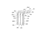
図1は、ここで提案される二次電池10の電極体20を示す斜視図である。図2は、電極体の構造を示す分解図である。図1に示す形態では、電極体20には、正極集電端子22と負極集電端子24が取り付けられている。電極体20は、正極集電端子22と、負極集電端子24とを通じて、電池ケース30の蓋32に取り付けられている。また、図1では、電池ケース30のケース本体34は、仮想線としての二点鎖線で示されている。電池ケース30は、いわゆる角型のケースであり、ケース本体34は、一面が開口した有底の直方体形状を有している。蓋32に取り付けられた電極体20は、電解質などとともに、ケース本体34に収容される。電解質には、例えば、有機溶媒にリチウム塩が溶解した電解液が用いられる。電解液には、例えば、エチレンカーボネート(EC)、ジメチルカーボネート(DMC)、エチルメチルカーボネート(EMC)などの非水溶媒の混合溶媒にLiPF6のような電解質を含有させた非水電解液などが挙げられる。
FIG. 1 is a perspective view showing an
電極体20は、図2に示すように、複数の正極シート20aと、複数の負極シート20bとが、セパレータ20cを介して交互に重ね合わされている。電極体20は、捲回されておらず、いわゆる積層型の電極体である。セパレータ20cは、例えば、所要の耐熱性を有する電解質が通過しうる多孔質の樹脂シートである。図2では、正極シート20aと、負極シート20bと、セパレータ20cは、位置をずらした状態で図示されている。また、図2では、2枚の正極シート20aと2枚の負極シート20bとが、セパレータ20cを介して重ね合わされる状態が示されている。電極体20はより多くの枚数の正極シート20aと負極シート20bとが、セパレータ20cを介して重ね合わされている。
As shown in FIG. 2, in the
正極シート20aは、正極集電箔20a1と、正極活物質層20a2とを有している。正極集電箔20a1は、矩形のシートである。矩形の正極集電箔20a1には、一辺に沿って露出部20a3が設定されている。正極活物質層20a2は、露出部20a3を除いて正極集電箔20a1に設けられている。この実施形態では、正極集電箔20a1は、アルミ箔である。正極活物質層20a2には、正極活物質が含まれている。正極活物質は、例えば、リチウムイオン二次電池では、リチウム遷移金属複合材料のように、充電時にリチウムイオンを放出し、放電時にリチウムイオンを吸収しうる材料である。正極活物質は、リチウム遷移金属複合材料以外にも種々提案されており、特に限定されない。
The
負極シート20bは、負極集電箔20b1と、負極活物質層20b2とを有している。負極集電箔20b1は、矩形のシートである。矩形の負極集電箔20b1には、一辺に沿って露出部20b3が設定されている。負極活物質層20b2は、露出部20b3を除いて負極集電箔20b1に設けられている。この実施形態では、負極集電箔20b1は、銅箔である。負極活物質層20b2には、負極活物質が含まれている。負極活物質は、例えば、リチウムイオン二次電池では、天然黒鉛のように、充電時にリチウムイオンを吸蔵し、充電時に吸蔵したリチウムイオンを放電時に放出しうる材料である。負極活物質は、天然黒鉛以外にも種々提案されており、特に限定されない。
The
正極集電箔20a1および負極集電箔20b1の厚さは、例えば、8μm〜20μm程度である。この実施形態では、正極活物質層20a2および負極活物質層20b2の厚さは、正極集電箔20a1または負極集電箔20b1の両面を合せて、例えば、20μm〜200μm程度とするとよい。 The thickness of the positive electrode current collecting foil 20a1 and the negative electrode current collecting foil 20b1 is, for example, about 8 μm to 20 μm. In this embodiment, the thickness of the positive electrode active material layer 20a2 and the negative electrode active material layer 20b2 may be, for example, about 20 μm to 200 μm when both sides of the positive electrode current collecting foil 20a1 or the negative electrode current collecting foil 20b1 are combined.
正極活物質層20a2と負極活物質層20b2とは、厚さ方向においてセパレータ20cを介在させて交互に重ね合わされている。ここで、負極活物質層20b2の幅b1は、正極活物質層20a2の幅a1よりも広く、セパレータ20cの幅c1は、負極活物質層20b2の幅b1よりも広い。正極活物質層20a2は、負極活物質層20b2によって覆われるように重ねられている。さらに正極活物質層20a2および負極活物質層20b2は、セパレータ20cによって覆われるように重ねられている。
The positive electrode active material layer 20a2 and the negative electrode active material layer 20b2 are alternately overlapped with the
複数の正極シート20aの露出部20a3(正極集電箔20a1に正極活物質層20a2が形成されていない部位)は、セパレータ20cの幅方向の片側において、それぞれはみ出ている。複数の負極シート20bの露出部20b3は、複数の正極シート20aの露出部20a3とは反対側において、セパレータ20cから、それぞれはみ出ている。
The exposed portions 20a3 of the plurality of
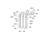
正極活物質層20a2と負極活物質層20b2とが重ね合わされた部位からはみ出た、複数の正極シート20aの露出部20a3は、図1に示すように、正極集電端子22に溶接されている。複数の正極シート20aの露出部20a3とは、反対側において、複数の負極シート20bの露出部20b3は、負極集電端子24に溶接されている。図3は、二次電池10の内部構造を示す正面図である。図3に示すように、この実施形態では、正極集電端子22は、電流遮断機構40を介在させて蓋32に取り付けられている。図4は、蓋32の平面図である。図5は、電流遮断機構40の断面図である。図5の断面は、図4のV−V断面である。図6は、正極集電端子22を示す斜視図である。図7は、正極集電端子22が電流遮断機構40のアッセンブリに組付けられた状態を示す斜視図である。図8は、電流遮断機構40が組付けられた正極集電端子22を内部側から見た斜視図である。図9は、負極集電端子24を示す斜視図である。
As shown in FIG. 1, the exposed portions 20a3 of the plurality of
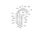
電流遮断機構40は、図5に示すように、反転板41と、接続部材42と、ガスケット43と、ホルダ部材44と、インシュレータ45とを備えている。蓋32には、電流遮断機構40が取り付けられる位置に取付孔32aが形成されている。ガスケット43は、絶縁性を有する筒状の部材であり、蓋32の取付孔32aに気密に装着されている。蓋32の内側面には、ガスケット43の周りにホルダ部材44が装着されている。ホルダ部材44は、胴部44aと、内フランジ44bと、カシメ部44cとを備えている。胴部44aは、略円筒状の部位である。胴部44aの一端には内フランジ44bが設けられている。内フランジ44bは、胴部44aの一端において内径側に突出している。内フランジ44bは、ガスケット43の周りにおいて、蓋32の内側面に当てられている。胴部44aは、蓋32の内側から突出している。カシメ部44cは、胴部44aの他端に設けられており、正極集電端子22に取り付けられる部位である。
As shown in FIG. 5, the
接続部材42は、筒状の部材であり、軸部42aと、円板部42bと、周縁部42cと、外鍔部42dとを備えている。軸部42aは、ガスケット43に装着される部位である。軸部42aの一端は、ガスケット43を介在させて蓋32の内側に延びている。軸部42aの一端には、円板部42bが設けられている。円板部42bは、蓋32の内側において、ガスケット43と、ホルダ部材44の内フランジ44bとを介在させて、軸部42aの外径方向に沿って延びている。周縁部42cは、円板部42bの外周縁において蓋32から離れる方向に延びた筒状の部位である。反転板41は、中央に平坦部41aを有するとともに、中央に向かって徐々に窪んだ略円錐状の薄板部材である。反転板41の外周縁41bは、周縁部42cの先端部に溶接されている。
The connecting
インシュレータ45は、絶縁性を有する樹脂製の部材である。インシュレータ45は、挿通孔45aと、台座部45bとを有している。挿通孔45aは、接続部材42の軸部42aに挿通する孔である。台座部45bは、外部端子51を所定の位置に配置するための窪みである。インシュレータ45は、挿通孔45aに接続部材42の軸部42aを挿通させて、蓋32の外側に配置されている。インシュレータ45の表面には、台座部45bが設けられている。外部端子51は、接続部材42の軸部42aに装着される装着孔51aが形成されている。外部端子51は、接続部材42の軸部42aに装着され、かつ、インシュレータ45の台座部45bに配置されている。軸部42aの先端には、外鍔部42dが設けられている。外鍔部42dは、軸部42aの先端が押し広げられて、インシュレータ45の台座部45bに配置された外部端子51の装着孔51aの周りにかしめられた部位である。
The
正極集電端子22は、図3および図6に示すように、基板部22aと、集電板部22bとを備えている。この実施形態では、基板部22aは、平板状の部位であり、中央部に薄肉部22a1が形成されている。正極集電端子22の基板部22aの四隅には、電流遮断機構40を取り付けるための取付孔22a2が形成されている。薄肉部22a1には、図5に示すように、電流遮断機構40の反転板41の中央部が溶接される。また、取付孔22a2は、電流遮断機構40のホルダ部材44のカシメ部44cに取り付けられる。集電板部22bは、基板部22aから連続し、基板部22aに対して直交する方向に沿って延びている。
As shown in FIGS. 3 and 6, the positive electrode current collecting
この実施形態では、集電板部22bは、平板状である。集電板部22bには、集電板部22bの先端から基板部22aに対して直交する方向に沿って延びるように複数のスリット22cが形成されている。スリット22cの本数は、図6に示す例では、3本である。スリット22cの本数は、この実施形態に限定されず、2本以上形成されているとよい。ここで、正極集電端子22の基板部22aは、適宜に第1基板部と称される。正極集電端子22の集電板部22bは、適宜に第2集電板部と称される。
In this embodiment, the current
複数のスリット22cは、図1に示すように、それぞれ正極シート20aの露出部20a3が束ねられて挿入される。このため、複数のスリット22cの幅(隙間)は、束ねられた正極シート20aの露出部20a3が挿入されうるように、それぞれ所要の幅で設定されているとよい。
複数のスリット22cは、それぞれ集電板部22bの先端部において先端側ほどスリット22cの幅(隙間)が広くなっている。この実施形態では、スリット22cの先端は、徐々に拡がっている。例えば、集電板部22bの先端部において、スリット22cの両側の縁は45°以上70°以下程度の角度αで拡がっているとよい。
As shown in FIG. 1, the plurality of
Each of the plurality of
この実施形態では、基板部22aと集電板部22bとの間は、Rを付けて折り曲げられている。複数のスリット22cは、それぞれ基板部22aと集電板部22bとの間の、かかるR部22dに至るまで連続して形成されている。さらに、この実施形態では、複数のスリット22cは、それぞれ基板部22aまで至っている。
In this embodiment, the
複数のスリット22cの縁には、適当な位置に切り欠き22c1が形成されている。この実施形態では、正極集電端子22の複数のスリット22cには、全てのスリット22cの両側の縁に、切り欠き22c1が形成されている。切り欠き22c1は、R部22dから延びた集電板部22bの長さ方向の中間位置とR部22dとの間に形成されている。切り欠き22c1は、好ましくは、例えば、集電板部22bの外側面における集電板部22bの長さ方向においてR部22d側の基端から20mmの範囲内に形成されているとよい。切り欠き22c1は、例えば、スリット22cの延びる方向(換言すると、基板部22aから延びた集電板部22bの長さ方向)に直交する方向に形成された切り込みであるとよい。切り欠き22c1の形状は特に限定されない。切り欠き22c1は、例えば、スリット22cの縁を半円状に切り欠いたものでもよいし、V字に切り欠いたものでもよい。スリット22cの縁が切り欠き22c1によって切り欠かれた幅は、例えば、集電板部22bの厚さと同程度であるとよい。
Notches 22c1 are formed at appropriate positions on the edges of the plurality of
この二次電池10では、図1に示すように、正極シート20aの露出部20a3は、3つの束に束ねられ、それぞれ正極集電端子22の集電板部22bに形成されたスリット22cに装着される。具体的には、正極シート20aと負極シート20bとが重ねられた電極体20の幅方向の片側において、セパレータ20cからはみ出た正極シート20aの露出部20a3に対して、上方から正極集電端子22は集電板部22bの先端を近づけていく。そして、正極シート20aの露出部20a3は、集電板部22bに形成された複数(この実施形態では、3本)のスリット22cに対してそれぞれ束ねられつつ、スリット22cの先端の拡がった部分に沿って、スリット22c内に挿入される。
In the
集電板部22bに形成された複数のスリット22cに対してスムーズに露出部20a3が束ねられるように、例えば、正極シート20aを重ねる際に適当な位置にシートを挟んでおくと良い。当該シートによって、予め定められた枚数の露出部20a3を束ねつつスリット22cに案内し、スリット22cに挿入するとよい。図1に示すように、スリット22cに露出部20a3が装着された後、露出部20a3を案内するために用いられたシートは抜き取るとよい。また、正極集電端子22のスリット22cを露出部20a3に向けて案内する前に、設備に設けられた把持ハンドなどによって、露出部20a3を適当な束に纏めて保持しておいてもよい。
For example, when stacking the
次に、図1に示すように、スリット22cに対して露出部20a3が装着された後は、集電板部22bの両側縁22b1を挟むようにプレスし、スリット22cに装着された露出部20a3を挟む。正極集電端子22のスリット22cには、切り欠き22c1が形成されている。集電板部22bの両側縁22b1を挟むようにプレスし、スリット22cに装着された露出部20a3を挟む際に、スリット22cの両側の縁が切り欠き22c1を起点に変形する。
Next, as shown in FIG. 1, after the exposed portion 20a3 is attached to the
このため、スリット22cに装着された露出部20a3を挟むのに要するプレス荷重が小さくなる。また、スリット22cに装着された露出部20a3を挟む際に、スリット22cの両側の縁が切り欠き22c1を起点に変形するので、スリット22cの両側の縁がスリット22cに装着された露出部20a3に沿って変形する。このため、スリット22cの両側の縁と、露出部20a3とに生じる隙間が小さくなる。さらに、この実施形態では、切り欠き22c1は、R部22dから延びた基板部22aの長さ方向の中間位置とR部22dとの間に形成されている。このため、スリット22cの両側の縁は、基板部22aに近い側で変形する。このため、スリット22cの両側の縁は、露出部20a3に十分に密着した部位が設けられる。
Therefore, the press load required to sandwich the exposed portion 20a3 mounted on the
このようにスリット22cと露出部20a3との隙間が小さくなる。この状態で、スリット22cおよびスリット22cに挟まれた露出部20a3にレーザーLを当てて、正極シート20aの露出部20a3と集電板部22bとをレーザー溶接する。これによって、正極シート20aと正極集電端子22とを十分な強度で溶接することができる。
In this way, the gap between the
スリット22cに装着された露出部20a3が挟まれる際に、スリット22cの両側の縁は切り欠き22c1を起点に変形する。集電板部22bに生じる変形は、かかる切り欠き22c1を起点とするので、基板部22aに生じる歪みが小さい。例えば、集電板部22bの両側縁22b1を挟むようにプレスされることによって、基板部22aを外側に撓ませるような力が作用する。このような力に対して、基板部22aが外側に撓むような変形が小さく抑えられる。
When the exposed portion 20a3 mounted on the
図3に示すように、正極集電端子22の基板部22aには、電流遮断機構40が設けられうる。電流遮断機構40は、基板部22aの中央部に薄肉部22a1が設けられており、反転板41が溶接されている。基板部22aに歪みが生じにくいので、薄肉部22a1に溶接された反転板41の動作にも不具合は生じにくい。
As shown in FIG. 3, a
負極集電端子24は、図3および図4に示すように、基板部24aと集電板部24bを備えている。集電板部24bは、基板部24aから連続し、基板部24aに対して直交する方向に沿って延びている。この実施形態では、基板部24aには、電池ケース30の外に突出する突起24a1が設けられている。突起24a1は外部端子53に接続される部位である。
As shown in FIGS. 3 and 4, the negative electrode current collecting
この実施形態では、集電板部24bは、平板状である。そして、図9に示すように、集電板部24bには、集電板部24bの先端から基板部24aに対して直交する方向に沿って延びるように複数のスリット24cが形成されている。そして、全てのスリット24cの両側の縁に切り欠き24c1が形成されている。
In this embodiment, the current
負極シート20bの露出部20b3は、集電板部24bに形成されたスリット24cに対して、それぞれ束ねられて装着されている。スリット24cに対して露出部20b3が装着された後は、集電板部24bの両側縁24b1を挟むようにプレスし、スリット24cに装着された露出部20b3を挟む。負極集電端子24のスリット24cには、切り欠き24c1が形成されている。集電板部24bの両側縁24b1を挟むようにプレスし、スリット24cに装着された露出部20b3を挟む際に、スリット24cの両側の縁が切り欠き24c1を起点に変形する。このため、スリット24cに装着された露出部20b3を挟むのに要するプレス荷重が小さくなる。
The exposed portions 20b3 of the
また、スリット24cに装着された露出部20b3を挟む際に、スリット24cの両側の縁が切り欠き24c1を起点に変形するので、スリット24cの両側の縁がスリット24cに装着された露出部20b3に沿って変形する。このため、スリット24cの両側の縁と、露出部20b3とに生じる隙間が小さくなる。さらに、この実施形態では、切り欠き24c1は、R部24dから延びた基板部24aの長さ方向の中間位置とR部24dとの間に形成されている。このため、スリット24cの両側の縁は、基板部24aに近い側で変形する。このため、スリット24cの両側の縁は、露出部20b3に十分に密着した部位が設けられる。
Further, when sandwiching the exposed portion 20b3 mounted on the
また、集電板部24bの両側縁24b1を挟むようにプレスし、スリット24cに装着された露出部20b3を挟む際に、基板部24aに生じる変形が小さく抑えられる。図3に示すように、負極集電端子24は、ガスケット46と、インシュレータ47とを介して蓋32に装着されており、かつ、外部端子53に接続されている。蓋32には、負極集電端子24が取り付けられる位置に取付孔(図示省略)が形成されている。ガスケット46は、蓋32の内側面および取付孔の周りに装着されている。負極集電端子24は、ガスケット46介在させて、蓋32の内側から基板部24aに設けられた突起24a1を蓋32の取付孔に装着する。インシュレータ47および外部端子53は、突起24a1が挿通される挿通孔(図示省略)を有している。蓋32の外側に突出した突起24a1にインシュレータ47およびインシュレータ47に装着された外部端子53の挿通孔を挿通し、インシュレータ47および外部端子53を取り付ける。そして、突起24a1の先端を押し広げて外部端子53の挿通孔の周りにかしめる。
Further, when pressing is performed so as to sandwich the both side edges 24b1 of the current
負極集電端子24は、スリット24cに切り欠き24c1が形成されているので、基板部24aに生じる変形が小さく抑えられる。このため、負極集電端子24と、ガスケット46と、蓋32との間に隙間が生じ難く、気密性を確保する観点において、不具合が生じにくい。
Since the negative electrode current collecting
露出部20b3は、スリット24cに挟まれた状態でレーザー溶接されて、負極集電端子24に接続されている。これによって、負極シート20bと負極集電端子24とが溶接されている。ここで、負極集電端子24の基板部24aは、正極集電端子22の基板部22aと区別するため適宜に第2基板部と称される。負極集電端子24の集電板部24bは、正極集電端子22の集電板部22bと区別するため適宜に第2集電板部と称される。
The exposed portion 20b3 is laser-welded while being sandwiched between the
この実施形態では、正極集電端子22と負極集電端子24の集電板部22b,24bの構造は、大凡同じである。また、負極集電端子24の集電板部24bに形成されたスリット24cに対して、負極シート20bの露出部20b3を装着し、溶接する工程も、正極集電端子22と同様である。これらについて、重複する説明を省略する。
In this embodiment, the structures of the current
ここで正極集電端子22および負極集電端子24は、例えば、金属製の板材を、プレス加工によって、基板部22a,24aおよび集電板部22b,24bに応じた所定形状に打ち抜き、複数のスリット22c,24cに応じたスリットを形成し、その後、折り曲げて形成するとよい。正極集電端子22および負極集電端子24には、それぞれ電池反応中の所要の電位に耐えうる材料が選択されるとよい。正極集電端子22は、例えば、アルミニウムまたはアルミ合金製であるとよい。負極集電端子24は、例えば、銅または銅合金製であるとよい。また、正極集電端子22の基板部22aと集電板部22b、および、負極集電端子24の基板部24aと集電板部24bは、それぞれ板状であるが、それぞれ所要の厚さを有しているとよい。
Here, the positive electrode current collecting
図3は、電極体20に取り付けられた正極集電端子22と負極集電端子24とを図示した正面図である。この二次電池10によれば、正極集電端子22および負極集電端子24は、それぞれ板状の基板部22a,24aと集電板部22b,24bとで構成されている。そして、基板部22a,24aと集電板部22b,24bとは、概ね直角に折れ曲っており、電極体20の角部に合せて配置されている。この実施形態では、正極集電端子22と負極集電端子24とが、それぞれ板状であり、配置される領域の省スペース化が図られている。
FIG. 3 is a front view showing the positive electrode current collecting
電極体20、正極集電端子22および負極集電端子24は、ガスケットや絶縁フィルムを介在させて電池ケース内に配置される。電池ケース30の中で、正極集電端子22と負極集電端子24をコンパクトに配置できるので、電極体20を大きくできる。特に、正極活物質層20a2と負極活物質層20b2とが重なる面積を広くできる。つまり、電池反応に寄与する正極活物質層20a2と負極活物質層20b2との有効面積を広く確保できる。これによって、同体積の二次電池であれば、二次電池の電池容量を大きくできる。つまり、二次電池の高容量化、エネルギーの高密度化が図られる。
The
この実施形態では、正極集電端子22および負極集電端子24の集電板部22b,24bに形成された複数のスリット22c,24cは、それぞれ集電板部22b,24bの先端部において先端側ほどスリット22c,24cの幅が広くなっている。この正極集電端子22と負極集電端子24は、上述のように、電極体20の上方から集電板部22b,24bを近づけ、正極シート20aの露出部20a3と負極シート20bの露出部20b3をスリット22c,24cにそれぞれ挿入することができる。ここで、電極体20の上方は、換言すると、電極体20に基板部22a,24aが対向するように配置される側(さらに換言すると、この実施形態では、蓋32に対向する側)である。
In this embodiment, the plurality of
正極シート20aの露出部20a3や負極シート20bの露出部20b3は、薄いシートの束であり、シートの長さ方向(セパレータ20cからはみ出た方向)に押されると曲がりやすい。これに対して、正極シート20aの露出部20a3と負極シート20bの露出部20b3は、シートの長さ方向とは直交する側の縁から、正極集電端子22および負極集電端子24のスリットに挿入される。このため、挿入される際に曲がりにくい。さらに、この実施形態では、スリット22c,24cは、それぞれ集電板部22b,24bの先端部において先端側ほどスリット22c,24cの幅が広くなっているので、正極シート20aの露出部20a3と負極シート20bの露出部20b3が挿入される際の取り扱いが容易である。
The exposed portion 20a3 of the
また、この実施形態では、集電板部22b,24bは、それぞれ平板状である。このため、スリット22c,24cが挿入される方向に対して直線上であり、正極シート20aの露出部20a3と負極シート20bの露出部20b3がスムーズに挿入されやすい。また、集電板部22b,24bを、電極体20の正極活物質層20a2と負極活物質層20b2とが重なる部位に近づけることができる。このことは、正極活物質層20a2と負極活物質層20b2とが重なる面積を広くすることに寄与する。つまり、電池反応に寄与する正極活物質層20a2と負極活物質層20b2との有効面積を広く確保できる。これによって、二次電池の電池容量を大きくできる。
Further, in this embodiment, the current
また、この実施形態では、正極集電端子22および負極集電端子24の基板部22a,24aと集電板部22b,24bとは曲って連続している。集電板部22b,24bに形成された複数のスリット22c,24cは、それぞれ基板部22a,24aと集電板部22b,24bとの間のR部22d,24dに至っている。上述のように、正極シート20aの露出部20a3と負極シート20bの露出部20b3は、集電板部22b,24bに形成された複数のスリット22c,24cにそれぞれ挿入される。
Further, in this embodiment, the
その後、集電板部22b,24bの両側縁22b1,24b1を挟むようにプレスし、スリット22c,24cの両側の縁によって、露出部20a3,20b3を挟む。この際、スリット22c,24cの両側の縁に切り欠き22c1,24c1が形成されている。このため、スリット22c,24cの両側の縁は、切り欠き22c1,24c1を起点にして変形する。このため、スリット22c,24cと露出部20a3,20b3との隙間が小さくなる。また、スリット22c,24cの両側の縁は、切り欠き22c1,24c1を起点にして変形する。このため、変形に伴う歪みが、基板部22a,24aにまで及びにくい。結果、かかる切り欠き22c1,24c1が形成されていない場合に比べて、基板部22a,24aに生じる歪みは小さくなる。
After that, the current
この実施形態では、正極集電端子22の基板部22aには、図5に示すように、電流遮断機構40の各部材が取り付けられる。上述のように集電板部22bのスリット22cの縁に切り欠き22c1が形成されていることによって、基板部22aに生じる歪みが小さい。このため、基板部22aは大凡平坦な状態に維持される。このため、基板部22aに取り付けられる電流遮断機構40に不具合が生じ難い。また、図3に示すように、負極集電端子24についても、負極シート20bの露出部20b3を挟む際に基板部24aに生じる歪みが小さい。負極集電端子24の基板部24aは、ガスケット46を介して蓋32に取り付けられる。上述のように集電板部24bのスリット24cの縁に切り欠き24c1が形成されていることによって、負極集電端子24の基板部24aに生じる歪みが小さい。このため、負極集電端子24が蓋32に取り付けられる際に、蓋32とガスケット46と負極集電端子24との取り付け部分に隙間が生じにくく、不具合が起きにくい。
In this embodiment, as shown in FIG. 5, each member of the
また、複数のスリット22c,24cは、それぞれ基板部22a,24aと集電板部22b,24bとの間のR部22d,24dに至っているので、露出部20a3,20b3が、スリット22c,24cに対して深く装着される。このため、正極集電端子22および負極集電端子24の基板部22a,24aを電極体20に近づけて配置することができる。このため、電池ケース30の中で、正極集電端子22と負極集電端子24をコンパクトに配置できるので、電極体20を大きくできる。特に、正極活物質層20a2と負極活物質層20b2とが重なる面積を広くでき、電池容量を大きくできる。また、レーザー溶接において、レーザー光が電極体20の内側に漏れにくく、適切にレーザー溶接される。これによって、正極集電端子22と正極シート20aの露出部20a3との溶接品質、および、負極集電端子24と負極シート20bの露出部20b3との溶接品質を向上させることができる。なお、正極集電端子22と正極シート20aの露出部20a3との溶接、および、負極集電端子24と負極シート20bの露出部20b3との溶接は、それぞれレーザー溶接に限定されず、適当な溶接方法が採用されうる。
Further, since the plurality of
さらに、この実施形態では、集電板部22b,24bの複数のスリット22c,24cは、それぞれ基板部22a,24aに至っている(図2参照)。このため、より小さい力で集電板部22b,24bを変形させることができる。そして、スリット22c,24cの内側面と露出部20a3,20b3との隙間をより小さくできる。
Further, in this embodiment, the plurality of
この実施形態では、図2に示すように、集電板部22b,24bの複数のスリット22c,24cは、それぞれ基板部22a,24aに至っている形態を例示している。正極集電端子22と負極集電端子24は、かかる形態に限定されない。正極集電端子22および負極集電端子24は、それぞれ板状の基板部22a,24aと集電板部22b,24bとで構成されている。そして、基板部22a,24aと集電板部22b,24bとは、折れ曲っており、電極体20の角部の直交する一辺に沿って配置されている。かかる形態において、電池反応に寄与する正極活物質層20a2と負極活物質層20b2との有効面積を広く確保するとの観点では、スリット22c,24cは、集電板部22b,24bにある程度の深さ(幅)で形成されているとよい。これによって、電池ケース30内の正極活物質層20a2と負極活物質層20b2とが重なる面積を広くでき、同じ体積の電池ケース30を用いた場合でも電池容量を大きくできる。つまり、二次電池10のエネルギー密度を高密度かできる。かかる観点において、スリット22c,24cは、R部22d,24dまたは基板部22a,24aに至っていなくてもよい。
In this embodiment, as shown in FIG. 2, the plurality of
この実施形態では、集電板部22b,24bの全てのスリット22c,24cの両側の縁にそれぞれ切り欠き22c1,24c1が形成されている。切り欠き22c1,24c1は、集電板部22b,24bの複数のスリット22c,24cのうち、一部のスリット22c,24cの縁に形成されているとよい。つまり、切り欠き22c1,24c1は、全てのスリット22c,24cの両側の縁にそれぞれ形成されている必要はない。なお、好ましい一形態として、切り欠き22c1,24c1は、集電板部22b,24bの全てのスリット22c,24cの少なくともいずれかの縁にそれぞれ形成されているとよい。また、より好ましくは切り欠き22c1,24c1は、集電板部22b,24bの全てのスリット22c,24cの両側の縁にそれぞれ形成されているとよい。
In this embodiment, notches 22c1, 24c1 are formed on both side edges of all the
また、スリット22c,24cの縁に加え、あるいは、スリット22c,24cの縁に代えて、集電板部22b,24bの基板部22a,24aに対して直交する方向に沿って延びた縁22b1,24b1に切り欠きが形成されていてもよい。集電板部22b,24bの基板部22a,24aに対して直交する方向に沿って延びた縁22b1,24b1に切り欠きが形成されている場合も、より小さい力で集電板部22b,24bを変形させることができる。そして、スリット22c,24cの内側面と露出部20a3,20b3との隙間をより小さくできる。このように、正極集電端子22と負極集電端子24の複数のスリット22c,24cの縁、および、集電板部22b,24bの基板部22a,24aに対して直交する方向に沿って延びた縁22b1,24b1のうち、少なくとも1つの縁に切り欠きが形成されているとよい。これによって、小さい力で集電板部22b,24bを変形させることができ、スリット22c,24cの内側面と露出部20a3,20b3との隙間をより小さくできる。縁22b1,24b1には、複数の切り欠きが形成されていてもよい。また、縁22b1,24b1に形成される切り欠きは、例えば、集電板部22b,24bの長さ方向の中間位置とR部22d,24dとの間に形成されているとよい。
Further, in addition to the edges of the
以下、正極集電端子22の例に、切り欠き22c1が設けられる位置について、変形例を例示する。図10〜16は、正極集電端子22について、種々の変形例を示す斜視図である。
Hereinafter, a modified example of the position where the notch 22c1 is provided will be illustrated in the example of the positive electrode current collecting
正極集電端子22は、集電板部22bに形成された複数のスリット22cのうち、1部のスリット22cの縁には、切り欠き22c1が形成されていなくてもよい。例えば、図10に示される形態では、集電板部22bに形成された3本のスリット22cのうち、真ん中のスリット22cの左側の縁には、切り欠き22c1が形成されていない。
The positive electrode current collecting
正極集電端子22は、集電板部22bに形成された複数のスリット22cが設けられる位置は、適宜に調整されうる。例えば、図11に示された形態では、集電板部22bに形成された3本のスリット22cのうち、真ん中のスリット22cの縁に切り欠き22c1が形成された位置よりも、両側のスリット22cの縁に切り欠き22c1が形成された位置は、R部22dに近い。また、例えば、図12に示された形態では、集電板部22bに形成された3本のスリット22cのうち、両側のスリット22cの縁には、複数(2つ)の切り欠き22c1が形成されている。
The position of the positive electrode current collecting
また、図13に示された形態では、集電板部22bに形成された3本のスリット22cは、それぞれ基板部22aにおいて、電流遮断機構40に干渉しない位置まで延びている。そして、各スリット22cには、それぞれ基板部22aに切り欠き22c1が形成されている。図14に示された形態では、集電板部22bに形成された3本のスリット22cは、それぞれR部22dに到達していない。その余の点で、図12に示された形態と同じである。さらに図15に示された形態では、スリット22cの縁に加えて、集電板部22bの基板部22aに対して直交する方向に沿って延びた縁22b1に切り欠き22b2が形成されている。図16に示された形態では、スリット22cの縁には切り欠きは形成されていないが、集電板部22bの基板部22aに対して直交する方向に沿って延びた縁22b1に切り欠き22b2が形成されている。このように、切り欠きは、スリット22c,24cの縁および集電板部22b,24bの縁22b1,24b1のうち少なくとも1つの縁に形成されているとよい。切り欠きの形状や、縁に切り欠きが形成される位置や数などは、図示された実施形態に限定されず適宜に変更されうる。このように種々変形例を例示しているが、本願で提案される集電端子の構成は、かかる形態に限定されない。各変形例で示された構成は、適宜に組み合せられうる。
Further, in the form shown in FIG. 13, the three
このように集電板部22b,24bの両側縁22b1,24b1を挟むようにプレスした際に、スリット22c,24cの両側の縁によって、露出部20a3,20b3が適切に挟まれるとよい。また、集電板部22b,24bの変形に伴って基板部22aに生じる歪みが小さく抑えられるとよい。かかる観点において、集電板部22b,24bの複数のスリット22c,24cのうち、適当なスリット22c,24cの縁の適当な位置に切り欠き22c1,24c1が形成されているとよい。かかる観点において、例えば、切り欠き22c1は、正極集電端子22の複数のスリット22cのうち少なくとも1つのスリットの縁に形成されているとよい。また、切り欠き24c1は、負極集電端子24の複数のスリット24cのうち少なくとも1つのスリットの縁に形成されているとよい。この場合、スリット22c,24cの縁に切り欠き22c1,24c1が形成されていない場合に比べて、集電板部22b,24bの変形に伴う基板部22aに生じる歪みが小さく抑えられうる。
When the current
また、図1に示す例では、電流遮断機構40が正極集電端子22に取り付けられているが、電流遮断機構40は、正極集電端子22と負極集電端子24のうち少なくとも何れか一方に設けられているとよい。このため、電流遮断機構40は、負極集電端子24に取り付けられていてもよい。また、二次電池10は、電流遮断機構40がなくてもよい。
Further, in the example shown in FIG. 1, the
また、この実施形態では、正極集電端子22および負極集電端子24は、一枚の板をプレス加工したものを例示した。この場合、基板部22a,24aと集電板部22b,24bとは曲って連続している。正極集電端子22および負極集電端子24は、かかる形態に限定されない。例えば、基板部22a,24aと集電板部22b,24bとは、それぞれ平板を溶接したものでもよい。
Further, in this embodiment, the positive electrode current collecting
以上、ここで提案される二次電池および集電端子について、種々説明した。特に言及されない限りにおいて、ここで挙げられた二次電池および集電端子の実施形態などは、本発明を限定しない。 The secondary batteries and current collector terminals proposed here have been described in various ways. Unless otherwise specified, the embodiments of the secondary battery and the current collector terminal mentioned here do not limit the present invention.
10 二次電池
20 電極体
20a 正極シート
20a 露出部
20a1 正極集電箔
20a2 正極活物質層
20a3 露出部
20b 負極シート
20b1 負極集電箔
20b2 負極活物質層
20b3 露出部
20c セパレータ
22 正極集電端子
22a 基板部
22a1 薄肉部
22a2 取付孔
22b 集電板部
22b1 両側縁
22b2 切り欠き
22c スリット
22c1 切り欠き
22d R部
24 負極集電端子
24a 基板部
24a1 突起
24b 集電板部
24b1 両側縁
24c スリット
24c1 切り欠き
24d R部
30 電池ケース
32 蓋
32a 取付孔
34 ケース本体
40 電流遮断機構
41 反転板
41a 平坦部
41b 外周縁
42 接続部材
42a 軸部
42b 円板部
42c 周縁部
42d 外鍔部
43 ガスケット
44 ホルダ部材
44a 胴部
44b 内フランジ
44c カシメ部
45 インシュレータ
45a 挿通孔
45b 台座部
46 ガスケット
47 インシュレータ
51 外部端子
51a 装着孔
53 外部端子
L レーザー
10
Claims (12)
複数の負極シートと、
正極集電端子と、
負極集電端子と
を備え、
前記正極シートは、
矩形の正極集電箔と、
前記矩形の正極集電箔に一辺に沿って設定された露出部を除いて前記正極集電箔に設けられた正極活物質層と
を有し、
前記負極シートは、
矩形の負極集電箔と、
前記矩形の負極集電箔に一辺に沿って設定された露出部を除いて前記負極集電箔に設けられた負極活物質層と
を有し、
前記正極活物質層と前記負極活物質層とは、
厚さ方向においてセパレータを介在させて交互に重ね合わされ、
前記複数の正極シートの前記露出部は、
前記セパレータの幅方向の片側にはみ出ており、
前記複数の負極シートの前記露出部は、
前記複数の正極シートの前記露出部とは反対側において、前記セパレータからはみ出ており、
前記正極集電端子は、
前記複数の正極シートの露出部に直交する面に沿って延びた第1集電板部と、
前記第1集電板部から連続し、前記複数の正極シートの露出部が設けられた一辺と直交する一辺に沿って延びた第1基板部と、
前記第1集電板部の先端から前記第1基板部に対して直交する方向に沿って形成された複数のスリットと、
前記正極集電端子の前記複数のスリットの縁および前記第1集電板部の前記第1基板部に対して直交する方向に沿って延びた縁のうち、少なくとも1つの縁に形成された切り欠きと
を備え、
前記負極集電端子は、
前記複数の負極シートの露出部に直交する方向に沿って延びた第2集電板部と、
前記第2集電板部から連続し、前記複数の負極シートの露出部が設けられた一辺と直交する一辺に沿って延びた第2基板部と、
前記第2集電板部の先端から前記第2基板部に対して直交する方向に沿って形成された複数のスリットと、
前記負極集電端子の前記複数のスリットの縁および前記第2集電板部の前記第2基板部に対して直交する方向に沿って延びた縁のうち、少なくとも1つの縁に形成された切り欠きと
を備え、
前記複数の正極シートの露出部は、前記正極集電端子の前記スリット内に挿入され、かつ、前記スリットの両側の縁に挟まれており、
前記複数の負極シートの露出部は、前記負極集電端子の前記スリット内に挿入され、かつ、前記スリットの両側の縁に挟まれている、
二次電池。 With multiple positive electrode sheets,
With multiple negative electrode sheets
Positive electrode current collector terminal and
Equipped with a negative electrode current collector terminal
The positive electrode sheet is
Rectangular positive electrode current collector foil and
It has a positive electrode active material layer provided on the positive electrode current collector foil except for an exposed portion set along one side of the rectangular positive electrode current collector foil.
The negative electrode sheet is
Rectangular negative electrode current collector foil and
It has a negative electrode active material layer provided on the negative electrode current collector foil except for an exposed portion set along one side of the rectangular negative electrode current collector foil.
The positive electrode active material layer and the negative electrode active material layer are
They are stacked alternately with separators in the thickness direction.
The exposed portion of the plurality of positive electrode sheets is
It protrudes to one side in the width direction of the separator and
The exposed portion of the plurality of negative electrode sheets is
On the side of the plurality of positive electrode sheets opposite to the exposed portion, the electrode protrudes from the separator.
The positive electrode current collecting terminal is
A first current collector plate portion extending along a plane orthogonal to the exposed portion of the plurality of positive electrode sheets, and a first collector plate portion.
A first substrate portion that is continuous from the first current collector plate portion and extends along one side that is orthogonal to the one side on which the exposed portions of the plurality of positive electrode sheets are provided.
A plurality of slits formed along a direction orthogonal to the first substrate portion from the tip of the first current collector plate portion, and
A cut formed on at least one of the edges of the plurality of slits of the positive electrode current collector terminal and the edges of the first current collector plate portion extending in a direction orthogonal to the first substrate portion. With notches,
The negative electrode current collector terminal
A second current collector plate portion extending in a direction orthogonal to the exposed portion of the plurality of negative electrode sheets, and a second current collector plate portion.
A second substrate portion continuous from the second current collector plate portion and extending along one side orthogonal to the one side on which the exposed portions of the plurality of negative electrode sheets are provided, and a second substrate portion.
A plurality of slits formed along a direction orthogonal to the second substrate portion from the tip of the second current collector plate portion, and
A cut formed on at least one edge of the edges of the plurality of slits of the negative electrode current collector terminal and the edges of the second current collector plate portion extending in a direction orthogonal to the second substrate portion. With notches,
The exposed portions of the plurality of positive electrode sheets are inserted into the slits of the positive electrode current collecting terminals and sandwiched between the edges on both sides of the slits.
The exposed portions of the plurality of negative electrode sheets are inserted into the slits of the negative electrode current collecting terminals and sandwiched between the edges on both sides of the slits.
Secondary battery.
前記第2基板部と前記第2集電板部とは曲って連続しており、前記第2集電板部の複数のスリットは、それぞれ前記第2基板部と前記第2集電板部との間のR部に至っている、
請求項1に記載された二次電池。 The first substrate portion and the first current collector plate portion are curved and continuous, and the plurality of slits of the first current collector plate portion are the first substrate portion and the first current collector plate portion, respectively. It reaches the R part between
The second substrate portion and the second current collector plate portion are curved and continuous, and the plurality of slits of the second current collector plate portion are the second substrate portion and the second current collector plate portion, respectively. It reaches the R part between
The secondary battery according to claim 1.
前記第2集電板部の前記複数のスリットは、それぞれ前記第2基板部に至っている、
請求項1または2に記載された二次電池。 The plurality of slits of the first current collector plate portion each reach the first substrate portion.
The plurality of slits in the second current collector plate portion each reach the second substrate portion.
The secondary battery according to claim 1 or 2.
前記負極集電端子の前記切り欠きは、前記第2集電板部の長さ方向の中間位置と前記R部との間に形成されている、請求項2または3に記載された二次電池。 The notch of the positive electrode current collecting terminal is formed between an intermediate position in the length direction of the first current collecting plate portion and the R portion.
The secondary battery according to claim 2 or 3, wherein the notch of the negative electrode current collector terminal is formed between an intermediate position in the length direction of the second current collector plate portion and the R portion. ..
前記負極集電端子に形成された前記複数のスリットの縁および前記第1集電板部の前記第1基板部に対して直交する方向に沿って延びた縁のうち、少なくとも1つの縁には、複数の切り欠きが形成されている、請求項1から4までの何れか一項に記載された二次電池。 At least one edge of the edges of the plurality of slits formed in the positive electrode current collector terminal and the edges of the first current collector plate portion extending in a direction orthogonal to the first substrate portion. , Multiple notches are formed, and
At least one edge of the edge of the plurality of slits formed in the negative electrode current collector terminal and the edge of the first current collector plate portion extending in a direction orthogonal to the first substrate portion. The secondary battery according to any one of claims 1 to 4, wherein a plurality of notches are formed.
前記第2集電板部の前記複数のスリットは、それぞれ前記第2集電板部の先端部において先端側ほどスリットの幅が広くなっている、請求項1から5までの何れか一項に記載された二次電池。 Each of the plurality of slits in the first current collector plate portion has a wider slit width toward the tip end portion of the first current collector plate portion.
The plurality of slits of the second current collector plate portion have a wider slit width toward the tip end portion of the second current collector plate portion, respectively, according to any one of claims 1 to 5. The listed secondary battery.
前記基板部から曲って連続し、前記基板部に対して直交する方向に沿って延びた集電板部と、
前記集電板部の先端から前記基板部に対して直交する方向に沿って延びるように形成された複数のスリットと、
前記複数のスリットの縁および前記集電板部の前記基板部に対して直交する方向に沿って延びた縁のうち、少なくとも1つの縁に形成された切り欠きと
を備え、
前記切り欠きは、前記基板部と前記集電板部とのうち、前記基板部と前記集電板部とが曲って連続した部位を除く部分に設けられている、集電端子。 Board part and
A current collector plate portion that is curved and continuous from the substrate portion and extends in a direction orthogonal to the substrate portion.
A plurality of slits formed so as to extend from the tip of the current collector plate portion in a direction orthogonal to the substrate portion, and
It is provided with a notch formed in at least one edge of the edges of the plurality of slits and the edge of the current collector plate portion extending in a direction orthogonal to the substrate portion.
The notch is a current collecting terminal provided in a portion of the substrate portion and the current collecting plate portion except for a portion where the substrate portion and the current collecting plate portion are bent and continuous.
Priority Applications (5)
| Application Number | Priority Date | Filing Date | Title |
|---|---|---|---|
| JP2017090316A JP6872143B2 (en) | 2017-04-28 | 2017-04-28 | Rechargeable battery and current collector terminal |
| DE102018107635.5A DE102018107635A1 (en) | 2017-04-28 | 2018-03-29 | Secondary battery and pantograph connection |
| KR1020180044423A KR102105290B1 (en) | 2017-04-28 | 2018-04-17 | Secondary battery and current collector terminal |
| US15/956,954 US10535858B2 (en) | 2017-04-28 | 2018-04-19 | Secondary battery and current collector terminal |
| CN201810355808.XA CN108808011B (en) | 2017-04-28 | 2018-04-19 | Secondary battery and current collecting terminal |
Applications Claiming Priority (1)
| Application Number | Priority Date | Filing Date | Title |
|---|---|---|---|
| JP2017090316A JP6872143B2 (en) | 2017-04-28 | 2017-04-28 | Rechargeable battery and current collector terminal |
Publications (2)
| Publication Number | Publication Date |
|---|---|
| JP2018190546A JP2018190546A (en) | 2018-11-29 |
| JP6872143B2 true JP6872143B2 (en) | 2021-05-19 |
Family
ID=63797356
Family Applications (1)
| Application Number | Title | Priority Date | Filing Date |
|---|---|---|---|
| JP2017090316A Active JP6872143B2 (en) | 2017-04-28 | 2017-04-28 | Rechargeable battery and current collector terminal |
Country Status (5)
| Country | Link |
|---|---|
| US (1) | US10535858B2 (en) |
| JP (1) | JP6872143B2 (en) |
| KR (1) | KR102105290B1 (en) |
| CN (1) | CN108808011B (en) |
| DE (1) | DE102018107635A1 (en) |
Families Citing this family (2)
| Publication number | Priority date | Publication date | Assignee | Title |
|---|---|---|---|---|
| CN111864172A (en) | 2019-04-25 | 2020-10-30 | 宁德时代新能源科技股份有限公司 | Battery unit and battery module |
| DE102020108579A1 (en) | 2020-03-27 | 2021-09-30 | Bayerische Motoren Werke Aktiengesellschaft | Current collector for an energy storage cell |
Family Cites Families (14)
| Publication number | Priority date | Publication date | Assignee | Title |
|---|---|---|---|---|
| JPS6129066A (en) * | 1984-07-19 | 1986-02-08 | Japan Storage Battery Co Ltd | Production of strap for alkaline storage battery |
| JP3804702B2 (en) | 1997-03-18 | 2006-08-02 | 株式会社ジーエス・ユアサコーポレーション | Nonaqueous electrolyte secondary battery |
| JP4564118B2 (en) * | 1999-10-26 | 2010-10-20 | パナソニック株式会社 | Battery and manufacturing method thereof |
| DE60128020T2 (en) * | 2000-03-14 | 2007-12-27 | Sanyo Electric Co., Ltd., Moriguchi | Non-aqueous electrolytic secondary cells |
| JP4918997B2 (en) | 2006-04-27 | 2012-04-18 | 株式会社デンソー | Nonaqueous electrolyte secondary battery |
| JP4462245B2 (en) * | 2006-07-19 | 2010-05-12 | トヨタ自動車株式会社 | Secondary battery, laminated secondary battery and assembled battery |
| JP4966677B2 (en) * | 2007-01-31 | 2012-07-04 | 日立ビークルエナジー株式会社 | Secondary battery and manufacturing method thereof |
| US8940420B2 (en) * | 2011-09-29 | 2015-01-27 | Samsung Sdi Co., Ltd. | Rechargeable battery |
| JP6079338B2 (en) | 2013-03-18 | 2017-02-15 | 株式会社豊田自動織機 | Power storage device and method for manufacturing power storage device |
| KR101724001B1 (en) * | 2013-04-17 | 2017-04-06 | 삼성에스디아이 주식회사 | Rechargeable battery |
| JP2015060742A (en) | 2013-09-19 | 2015-03-30 | トヨタ自動車株式会社 | Secondary battery |
| KR20170021119A (en) * | 2015-08-17 | 2017-02-27 | 삼성에스디아이 주식회사 | Rechargeable battery |
| JP6593304B2 (en) * | 2016-11-07 | 2019-10-23 | トヨタ自動車株式会社 | Electric storage device and method for manufacturing electric storage device |
| JP6872144B2 (en) * | 2017-04-28 | 2021-05-19 | トヨタ自動車株式会社 | Rechargeable battery and current collector terminal |
-
2017
- 2017-04-28 JP JP2017090316A patent/JP6872143B2/en active Active
-
2018
- 2018-03-29 DE DE102018107635.5A patent/DE102018107635A1/en active Pending
- 2018-04-17 KR KR1020180044423A patent/KR102105290B1/en active IP Right Grant
- 2018-04-19 CN CN201810355808.XA patent/CN108808011B/en active Active
- 2018-04-19 US US15/956,954 patent/US10535858B2/en active Active
Also Published As
| Publication number | Publication date |
|---|---|
| US20180315981A1 (en) | 2018-11-01 |
| JP2018190546A (en) | 2018-11-29 |
| CN108808011A (en) | 2018-11-13 |
| KR20180121367A (en) | 2018-11-07 |
| DE102018107635A1 (en) | 2018-10-31 |
| KR102105290B1 (en) | 2020-04-28 |
| US10535858B2 (en) | 2020-01-14 |
| CN108808011B (en) | 2021-02-23 |
Similar Documents
| Publication | Publication Date | Title |
|---|---|---|
| JP5336024B1 (en) | Secondary battery | |
| JP5841571B2 (en) | Secondary battery | |
| JP4514434B2 (en) | Secondary battery | |
| JP5803713B2 (en) | Power storage device and vehicle | |
| JP4484782B2 (en) | Secondary battery | |
| JP5564278B2 (en) | Secondary battery | |
| JP6891930B2 (en) | Square secondary battery and assembled battery using it | |
| US10424809B2 (en) | Secondary battery, method for manufacturing same, and battery pack employing same | |
| JP2019061779A (en) | Power storage device and power storage method | |
| JP7304330B2 (en) | secondary battery | |
| JP2020140874A (en) | Laminate outer package battery | |
| US11581544B2 (en) | Energy storage device and energy storage device production method | |
| JP6872143B2 (en) | Rechargeable battery and current collector terminal | |
| JP6872144B2 (en) | Rechargeable battery and current collector terminal | |
| JP6756336B2 (en) | Power storage element and manufacturing method of power storage element | |
| JP5957859B2 (en) | Electricity storage element | |
| CN106328843B (en) | Secondary battery | |
| JP2018147743A (en) | Electrode and nonaqueous electrolyte secondary battery | |
| JP2021120961A (en) | Square secondary battery and battery pack using the same | |
| JP2007207677A (en) | Process of manufacturing electrodes for square batteries, and electrodes for square batteries | |
| JP2019121457A (en) | Manufacturing method of power storage device, and power storage device | |
| WO2023037407A1 (en) | Battery | |
| JP6874695B2 (en) | Power storage element and manufacturing method of power storage element | |
| JP2022112412A (en) | Terminal component, secondary battery, and battery pack | |
| JP2020102418A (en) | Manufacturing method of electrode plate group for secondary battery, electrode plate group for secondary battery, and secondary battery |
Legal Events
| Date | Code | Title | Description |
|---|---|---|---|
| A621 | Written request for application examination |
Free format text: JAPANESE INTERMEDIATE CODE: A621 Effective date: 20191115 |
|
| A977 | Report on retrieval |
Free format text: JAPANESE INTERMEDIATE CODE: A971007 Effective date: 20200722 |
|
| A131 | Notification of reasons for refusal |
Free format text: JAPANESE INTERMEDIATE CODE: A131 Effective date: 20200813 |
|
| A521 | Request for written amendment filed |
Free format text: JAPANESE INTERMEDIATE CODE: A523 Effective date: 20201007 |
|
| TRDD | Decision of grant or rejection written | ||
| A01 | Written decision to grant a patent or to grant a registration (utility model) |
Free format text: JAPANESE INTERMEDIATE CODE: A01 Effective date: 20210318 |
|
| A61 | First payment of annual fees (during grant procedure) |
Free format text: JAPANESE INTERMEDIATE CODE: A61 Effective date: 20210331 |
|
| R151 | Written notification of patent or utility model registration |
Ref document number: 6872143 Country of ref document: JP Free format text: JAPANESE INTERMEDIATE CODE: R151 |