EP2264729A1 - Method and device for detecting failure of a vacuum interrupter of an on load tap changer - Google Patents
Method and device for detecting failure of a vacuum interrupter of an on load tap changer Download PDFInfo
- Publication number
- EP2264729A1 EP2264729A1 EP09163129A EP09163129A EP2264729A1 EP 2264729 A1 EP2264729 A1 EP 2264729A1 EP 09163129 A EP09163129 A EP 09163129A EP 09163129 A EP09163129 A EP 09163129A EP 2264729 A1 EP2264729 A1 EP 2264729A1
- Authority
- EP
- European Patent Office
- Prior art keywords
- oil
- failure
- tap changer
- hydrogen content
- vacuum interrupter
- Prior art date
- Legal status (The legal status is an assumption and is not a legal conclusion. Google has not performed a legal analysis and makes no representation as to the accuracy of the status listed.)
- Withdrawn
Links
Images


Classifications
-
- H—ELECTRICITY
- H01—ELECTRIC ELEMENTS
- H01H—ELECTRIC SWITCHES; RELAYS; SELECTORS; EMERGENCY PROTECTIVE DEVICES
- H01H9/00—Details of switching devices, not covered by groups H01H1/00 - H01H7/00
- H01H9/0005—Tap change devices
-
- H—ELECTRICITY
- H01—ELECTRIC ELEMENTS
- H01H—ELECTRIC SWITCHES; RELAYS; SELECTORS; EMERGENCY PROTECTIVE DEVICES
- H01H9/00—Details of switching devices, not covered by groups H01H1/00 - H01H7/00
-
- H—ELECTRICITY
- H01—ELECTRIC ELEMENTS
- H01F—MAGNETS; INDUCTANCES; TRANSFORMERS; SELECTION OF MATERIALS FOR THEIR MAGNETIC PROPERTIES
- H01F29/00—Variable transformers or inductances not covered by group H01F21/00
- H01F29/02—Variable transformers or inductances not covered by group H01F21/00 with tappings on coil or winding; with provision for rearrangement or interconnection of windings
- H01F29/04—Variable transformers or inductances not covered by group H01F21/00 with tappings on coil or winding; with provision for rearrangement or interconnection of windings having provision for tap-changing without interrupting the load current
-
- H—ELECTRICITY
- H01—ELECTRIC ELEMENTS
- H01H—ELECTRIC SWITCHES; RELAYS; SELECTORS; EMERGENCY PROTECTIVE DEVICES
- H01H9/00—Details of switching devices, not covered by groups H01H1/00 - H01H7/00
- H01H9/0005—Tap change devices
- H01H2009/0061—Monitoring tap change switching devices
-
- H—ELECTRICITY
- H01—ELECTRIC ELEMENTS
- H01H—ELECTRIC SWITCHES; RELAYS; SELECTORS; EMERGENCY PROTECTIVE DEVICES
- H01H9/00—Details of switching devices, not covered by groups H01H1/00 - H01H7/00
- H01H9/0005—Tap change devices
- H01H9/0038—Tap change devices making use of vacuum switches
Definitions
- the invention relates to a method and device for detecting failure of a vacuum interrupter in an on-load tap-changer, wherein the tap changer comprises; an oil filled housing, a diverter switch (3) including a movable contact (MC, RC), and at least one vacuum interrupter (MVI, RVI) arranged to interrupt a current through the movable contact of the diverter switch.
- a diverter switch (3) including a movable contact (MC, RC), and at least one vacuum interrupter (MVI, RVI) arranged to interrupt a current through the movable contact of the diverter switch.
- a tap changer is a device used with transformers for regulation of the voltage levels. This is achieved by having the tap changer altering the number of turns in a winding of the transformer.
- On load tap changers generally comprises of a diverter switch and a tap selector switch operating as a unit to effect transfer current from one voltage tap to the next.
- the diverter switch does the entire on load making and breaking of currents, whereas the tap selector pre-selects the tap to which the diverter switch will transfer the load current.
- the tap selector operates off load. When the power output from a transformer is to be changed from one voltage level to another, this occurs by first connecting the selector to that tapping point of the transformer winding which corresponds to the new voltage level while the diverter switch is still feeding from the existing voltage level.
- connection of the selector thus takes place without current load.
- a switching operation then takes with the aid of the diverter switch such that output current is taken out from the new tapping point of the transformer.
- a diverter switch of the kind referred to here is normally used for control of power or distribution transformers.
- the OLTC may also advantageously be used for control of other types of electrical devices, such as, power transmission or distribution products, such as reactors, industrial transformers, phase shifters, capacitors or the like.
- the operation of the diverter switch involves commutation from one circuit to another with ensuing occurrence of an electric arc.
- the diverter switch together with all subsystems is placed in a tank and submerged in oil.
- the on-load tap changer comprises the tank together with oil, diverter switches and subsystems.
- the oil in the tank acts as electric insulator and as a coolant to remove the generated heat in the OLTC.
- the oil will also quench the arcs generated during switching.
- the arcing during the operation of the OLTC will pollute the insulating oil and wear the switch contacts.
- a diverter switch of this kind is provided with at least one main branch and one resistance branch each with a vacuum interrupter.
- a diverter switch of the above kind is previously known from, for example, US 5,786,552 .
- the diverter switch described therein thus has one main branch and one resistance branch, in the steady state connected in parallel and connected to an output line.
- Each branch is provided with a vacuum switch and a contact connected in series therewith. These are operated in a definite sequence when diverter switching is to take place, in which case it is important to ensure that the main branch is operated before the resistance branch for the OLTC but for some load interrupters the main branch is not operated before the resistance branch.
- the vacuum switch of the main branch may be dimensioned for breaking of the load current only and the vacuum switch of the resistance branch for the circulating current that arises. In case of the reverse sequence, the vacuum switch of the main branch would be forced to break the sum of these currents and thus be dimensioned therefore.
- the auxiliary contact system in the OLTC is capable to break the current a limit number of operations, dependent of OLTC type and load, possibly between 10 to 500 times.
- auxiliary main contacts can not connect two things can happen:
- One object of the present invention is to provide a method for detecting failure of vacuum interrupters of a On-Load Tap-Changer (OLTC).
- OLTC On-Load Tap-Changer
- the method comprises repeatedly measuring a hydrogen content in the oil of the housing, and determining whether there is a failure in the vacuum interrupter based on the measurement of hydrogen content in the oil.
- Another object of the present invention is to provide a device for detecting failure of vacuum interrupters of a tap changer.
- the device comprises an oil filled housing arranged with a sensor 10 for repeatedly measuring the content of hydrogen in oil, and a computing unit is configured to analyze the measurements of hydrogen content in the oil and to determine if there is a failure in the vacuum interrupters (MVI, RVI).
- MVI, RVI vacuum interrupters
- the object of the invention is solved by realizing that if the vacuum interrupter fails, current is no longer interrupted by the vacuum interrupters but the auxiliary contact system.
- the auxiliary contact has to break the current, thus creating arcs in the oil.
- These arcs combined with the known fact that arcs in insulation oil increase the amount of hydrogen in the insulating oil.
- With a hydrogen sensor detecting the absolute amount of hydrogen in oil or the rate of change of hydrogen in oil, it is possible to detect that the vacuum interrupter has not been capable to break the current and thus allows the detection of vacuum interrupter failure.
- the method further comprises the step of;
- the determination whether there is a failure in the vacuum interrupter can be done by comparing the measured level of hydrogen in oil with a fixed maximum allowed hydrogen level and/or by comparing the increase of hydrogen in oil over time by using stored previous measurements of hydrogen in oil.
- the method further comprises the step of;
- the action can be to send a warning to the control system of the tap changer or transformer.
- the warning could also be sent to a plant wide control system.
- the action can also be to only allow a limited number of critical operations without overload of the diverter switch.
- the action can also be to stop the diverter switch from moving at all.
- the selected action can depend on the level of hydrogen in oil or the rate of increase of the level of hydrogen in oil.
- the OLTC When a serious vacuum interrupter failure has been detected the OLTC have to immediately stop maneuvering or only make a limited number of critical operations without overload if these are considered critical for the operation of the system it serves.
- the limited number of operations of the diverter switch can be less than 200 or even less that 20 until the OLTC have been checked by maintenance personnel.
- the transformer can still be used but the voltage level is no longer controllable but this is a preferred state to the case when the error is undetected and the OLTC undergoes a catastrophic failure.
- the step determining whether there is a failure in the vacuum interrupter comprises the steps of repeatedly;
- the operation of the tap changer is the timing of switching moves of the diverter switch and load current at the time of the switching moves.
- the model could be a physical model to project the hydrogen release based on the number of switches and the load current or the model could be a look-up model based on measurements and/or past data where the average hydrogen release is calculated based on the number of switches and the load current.
- the level of hydrogen in the tap changer oil will naturally vary dependent on how the tap changer is operated i.e. how often the taps are performed and what load currents have to be interrupted.
- This model based determination of vacuum interrupter failure is much less likely to make errors in determining failures than a system that only compares the measured hydrogen level in oil with an absolute hydrogen level. To make a faulty determination of vacuum interrupter failure could lead to an unnecessary shut down of the transformer - tap changer system. This unnecessary shut down would lead to a potential power loss of all connected systems e.g. industrial installation or residential housing which would be very expensive.
- the determination if there is a failure of the vacuum interrupter is based on if H 2 mes new - H 2 mes old - ⁇ ⁇ H 2 est > eps is true.
- H 2 mes (new) is a parameter describing the current measured hydrogen content in oil, this can be a single measurement or a some mean or average of a number of measurements.
- H 2 mes (old) is a parameter describing the previously measured hydrogen content in oil, this can be a single measurement or a some mean or average of a number of previous measurements.
- ⁇ H 2 est is an expected change in hydrogen content in oil based on operation of the tap changer.
- the operation of the tap changer is the timing of switching moves of the diverter switch and load current at the time of the switching moves.
- eps is a safety parameter that will ensure that a failure of the vacuum interrupter is not determined unless the measured increase in hydrogen is above eps.
- eps can be in the order of a few ppm up to several hundred ppm of hydrogen in oil, depending on type of tap-changer, load, age of oil and risk of a false alarm.
- the computing unit is configured to send a warning to the control system if a failure of the vacuum interrupters (MVI, RVI) is detected.
- MVI, RVI vacuum interrupters
- the computing unit is configured to send a signal to the control system to stop or limit movement of the diverter switch if a failure of the vacuum interrupters (MVI, RVI) is detected.
- MVI, RVI vacuum interrupters
- the computing unit is configured to receive data of the operation of the tap changer and said computing unit is configured to calculate an expected change in hydrogen content and compare the expected change in hydrogen content with the analyzed measurements of hydrogen content in the oil to determine failure in the vacuum interrupters (MVI, RVI).
- FIG. 1 shows schematically an on-load tap-changer 2 in a transformer 8 with an embodiment of the present invention.
- the tap-selector 1 is mounted beneath the diverter switch 3.
- the movements of the OLTC get the energy from a motor drive mechanism 9, here mounted on the wall of the transformer 8.
- the movements from the motor 9 are transferred by shafts 6', 6" and a bevel gear 7.
- An oil conservator 5 ensures that there is enough of oil in the OLTC at all temperatures.
- a hydrogen sensor device 10 is immersed in the oil, the placement in the drawing is only indicative it can be arranged anywhere in the housing.
- the hydrogen sensor device 10 signals to a drive control unit 11 which control the movements of the motor 9 driving the diverter switch 3.
- the transformer 8 and the OLTC 2 are both oil filled but have different housings and the oil in the OLTC and the oil in the transformer are never in contact. It is also possible to arrange the OLTC outside the transformer tank.
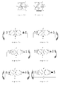
- Figures 2a-2e shows schematically the switching sequence of the on-load tap-changer from position 6 to position 5 on the transformer winding.
- the dominant electrical flows are indicated by the grey arrows.
- the sequence is designated the symmetrical flag cycle. This means that the main switching contact of the diverter switch breaks before the transition resistors are connected across the regulating step. This ensures maximum reliability when the switch operates with overloads.
- the breaking takes place at the first current zero after contact separation, which means an average arcing time of approximately 4-6 ms.
- the total time for a complete sequence is approximately 50 milliseconds.
- the tap change operation time of the motor-drive mechanism is approximately 5 s/step.
- Arcs occur in any of the movements where a contact is opened.
- Each level can be associated with different actions. For example, when the hydrogen concentration goes above 43 warning level 40, the control system alerts the monitoring system for the transformer or a plant wide control system alerting operators that something might not be OK with the tap changer. When the hydrogen concentration goes above 44 first alarm level 41, the control system alerts the monitoring system for the transformer or a plant wide control system alerting operators and will only perform the most necessary tap changes. When the hydrogen concentration goes above 45 second alarm level 42, the control system alerts the monitoring system for the transformer or a plant wide control system and alerting operators and stops all tap changes.
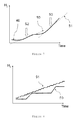
- Fig 7 shows a schematic view of a possible development of hydrogen content/concentration 46 in oil over time in the tap changer.
- the hydrogen detector measures the hydrogen concentration 46 in oil and the analysis of the measurement compares the measured hydrogen concentration data series with different warning or alarm levels of increase of hydrogen concentration.
- the rate of increase of measured hydrogen concentration is larger than a possible warning increase 50.
- the rate of increase of measured hydrogen concentration is larger than a possible alarm increase 51.
- the analysis of the data series 46 might include smoothing or filtering of the measured values.
- Fig 8 shows a schematic view of a possible development of hydrogen content/concentration 46 in oil over time in the tap changer where each tap change is associated with a up-tic of the concentration of hydrogen.
- the analysis system also have to include the frequency of tap changes or the time between taps.
- a large number of tap changes 51 might generate a larger increase of hydrogen than on with much fewer taps 50. But the increase of the curve 50 with few taps might indicate a problem.
- the system have to be able to separate the two cases 50, 51 and might give a warning/alarm for 50 but not for 51.
- the relative size of the curves and alarm levels in figures 6-8 are only for illustration.
- the arc in the main contacts has a current equal to the load current while the current in the transition contacts is composed by half the load current and the circulation current.
- the circulation current is dependent of the step voltage and the resistance of the transition resistor and is thus load independent.
- Each of these arcs lasts normally for max half a period and the average will be half a period that is 5 ms for 50 Hz.
- the energy in these arcs determines the amount of gas that is generated.
- the gas generation can be estimated to be linear with the energy dissipation of the arcs.
- the primary goal for an OLTC with arc quenching in vacuum interrupters is to prevent arcs in oil.
- the arcing in the oil gives several disadvantages such as higher erosion of the contact material in the breaking contacts and deterioration of the oil due to the high temperatures in the arcs.
- the deterioration of the oil generates substances that reduces the dielectric withstand of the oil, especially in the presence of moisture, as well as increases the wear of the mechanism.
- the diverter switch breaks the current from one tap before it connects the other one. In order not to generate interruptions in the circuit, the load current goes through the transition contacts during the time it takes for the main contacts to safely break the current from tap 1 until tap 2 is connected.
- auxiliary contact By designing the auxiliary contact such that they can break the load current or circulating current in case a vacuum interrupter fails, a much larger safety margin against such serious failures is obtained.
- auxiliary contacts are made primarily for conducting current the materials are selected for low resistance and not for good arc resistance. The goal is that they should be able to make half a cycle of operation while breaking maximum the rated load current with maintained function both as current conductor and as breaking contact.
- supervisory device must give alarm before the contacts are destroyed so much by the arcs that they not fulfils their functions.
- the aim is to give alarm not to trip the transformer. Since several operations are possible it does not need to trip the transformer.
- detections methods are possible such as pressure detection, oil flow detection (in the tube to the oil conservator), light detection, radio emission detection, etc.
- This invention deals with the possibility to use hydrogen concentration changes in the insulating oil as a parameter for detection of arcs in the oil.
- OLTCs with vacuum interrupters for high currents have normally by-pass contacts that are by-passing the vacuum interrupter circuit when the OLTC is in position, to prevent the vacuum interrupters to continuously conduct the current as well as to protect them from short-circuit currents.
- the by-pass contact will generate commutation sparks when the current is commutated from the by-pass path to the vacuum interrupter circuit due to the small inductances in the circuit. These sparks will generate small amounts of hydrogen. The energy released is though only a few percent of that of a real arc in the oil and the gas generation is in relation to that.
- OLTCs not having by-pass contacts do still have the auxiliary contacts. These do not commutate any current but during switching they are potentially disconnected shortly which give them a voltage that causes minor capacitive discharge sparks. The energy in these are even smaller than that from the commutation sparks in the by-pass contacts but will give rise to small amounts of hydrogen in the oil after a large amount of operations at voltage.
- compositions of these gases are such that about 75 % is hydrogen (H2) and about 20 % is acetylene (C2H2).
- H2 hydrogen
- C2H2 acetylene
- the composition will be closer to 100 % hydrogen.
- Acetylene is easily dissolved in oil due to its similarity with the hydrocarbons in oil while hydrogen is not easily dissolved.
- This method requires some intelligence and availability to information about when operations occur and the load of the transformer. But it gives the advantage of being more sensitive and reacting faster especially in applications with low currents and/or low operation frequency.
- This method is preferably used in combination with a transformer control and protection system, such as ABB TEC or similar, that already has access to the data needed. It can of course also be made with a separate unit
- the interpretation is made with a special program in the control system.
- the interpretation is made such that the change in concentration of hydrogen is related to the spark energy released per unit of time.
- the load current is available as well as the number of operation per unit of time. The arc energy might thus be easily calculated and the hydrogen concentration is related to that.
- the method automatically calculates the expected values within a certain tolerance width. This width can be quite large since the difference between the hydrogen generation at normal service and arcs in oil differ so much. Thus, the calculation does not need to be very precise.
Landscapes
- Engineering & Computer Science (AREA)
- Power Engineering (AREA)
- Housings And Mounting Of Transformers (AREA)
- Protection Of Transformers (AREA)
- High-Tension Arc-Extinguishing Switches Without Spraying Means (AREA)
Priority Applications (7)
| Application Number | Priority Date | Filing Date | Title |
|---|---|---|---|
| EP09163129A EP2264729A1 (en) | 2009-06-18 | 2009-06-18 | Method and device for detecting failure of a vacuum interrupter of an on load tap changer |
| BRPI1011777A BRPI1011777B8 (pt) | 2009-06-18 | 2010-06-17 | Método para detectar falha de um interruptor de vácuo em um trocador de derivação com carga e arranjo de trocador de derivação com carga |
| PCT/EP2010/058572 WO2010146131A1 (en) | 2009-06-18 | 2010-06-17 | Method and device for detecting failure of a vacuum interrupter of an on load tap changer |
| RU2012101612/07A RU2544844C2 (ru) | 2009-06-18 | 2010-06-17 | Способ и устройство для детектирования неисправности вакуумного прерывателя переключателя ответвлений под нагрузкой |
| CN201080027149.9A CN102460624B (zh) | 2009-06-18 | 2010-06-17 | 检测有载抽头变换器的真空断路器的故障的方法和设备 |
| EP10725719.8A EP2443641B1 (en) | 2009-06-18 | 2010-06-17 | Method and device for detecting failure of a vacuum interrupter of an on load tap changer |
| KR1020127001496A KR101517656B1 (ko) | 2009-06-18 | 2010-06-17 | 부하시 탭 전환기의 진공 차단기의 고장을 검출하기 위한 방법 및 디바이스 |
Applications Claiming Priority (1)
| Application Number | Priority Date | Filing Date | Title |
|---|---|---|---|
| EP09163129A EP2264729A1 (en) | 2009-06-18 | 2009-06-18 | Method and device for detecting failure of a vacuum interrupter of an on load tap changer |
Publications (1)
| Publication Number | Publication Date |
|---|---|
| EP2264729A1 true EP2264729A1 (en) | 2010-12-22 |
Family
ID=41314515
Family Applications (2)
| Application Number | Title | Priority Date | Filing Date |
|---|---|---|---|
| EP09163129A Withdrawn EP2264729A1 (en) | 2009-06-18 | 2009-06-18 | Method and device for detecting failure of a vacuum interrupter of an on load tap changer |
| EP10725719.8A Active EP2443641B1 (en) | 2009-06-18 | 2010-06-17 | Method and device for detecting failure of a vacuum interrupter of an on load tap changer |
Family Applications After (1)
| Application Number | Title | Priority Date | Filing Date |
|---|---|---|---|
| EP10725719.8A Active EP2443641B1 (en) | 2009-06-18 | 2010-06-17 | Method and device for detecting failure of a vacuum interrupter of an on load tap changer |
Country Status (6)
| Country | Link |
|---|---|
| EP (2) | EP2264729A1 (pt) |
| KR (1) | KR101517656B1 (pt) |
| CN (1) | CN102460624B (pt) |
| BR (1) | BRPI1011777B8 (pt) |
| RU (1) | RU2544844C2 (pt) |
| WO (1) | WO2010146131A1 (pt) |
Cited By (4)
| Publication number | Priority date | Publication date | Assignee | Title |
|---|---|---|---|---|
| JP2012243323A (ja) * | 2011-05-20 | 2012-12-10 | General Electric Co <Ge> | 故障ガス警報システム |
| GR20130100026A (el) * | 2012-03-22 | 2013-10-15 | Bharat Heavy Electricals Limited, | Βελτιωμενος μετασχηματιστης ισχυος με μεταγωγεα ληψεων για λειτουργια υπο φορτιο (oltc) τυπου κενου που μπορει να λειτουργει με μανομετρικο υψος ελαιου που υπερβαινει τα δεκα μετρα |
| EP2743943A1 (en) * | 2013-05-22 | 2014-06-18 | ABB Technology Ltd | Transformer tap changer |
| WO2015044331A1 (de) * | 2013-09-26 | 2015-04-02 | Maschinenfabrik Reinhausen Gmbh | Verfahren und system zum gasfreien betrieb eines stufenschalters mit vorwähler |
Families Citing this family (7)
| Publication number | Priority date | Publication date | Assignee | Title |
|---|---|---|---|---|
| EP2959493B1 (en) * | 2013-02-20 | 2017-04-12 | ABB Schweiz AG | Tap changer contact system |
| KR101623875B1 (ko) * | 2014-11-14 | 2016-06-07 | 주식회사 포스코 | 변압기 질소 충전 장치 및 질소 충전 방법 |
| US9679710B1 (en) | 2016-05-04 | 2017-06-13 | Cooper Technologies Company | Switching module controller for a voltage regulator |
| CN110114850B (zh) * | 2016-12-30 | 2021-12-14 | 日立能源瑞士股份公司 | 有载抽头变换器和制造有载抽头变换器的方法 |
| EP3745434B1 (en) * | 2019-05-28 | 2023-05-17 | Hitachi Energy Switzerland AG | Pressure pulse diagnostics of an on-load tap changer |
| CN113985270B (zh) * | 2021-11-02 | 2022-05-27 | 广东电网有限责任公司 | 一种有载分接开关切换时序检测方法、系统和介质 |
| CN116667721B (zh) * | 2023-07-31 | 2023-09-29 | 江西第二电力设备有限公司 | 一种电力变压器的调容调压方法及电力变压器 |
Citations (2)
| Publication number | Priority date | Publication date | Assignee | Title |
|---|---|---|---|---|
| US3206569A (en) * | 1964-12-17 | 1965-09-14 | Orin P Mccarty | Protective means for transformer tap changer |
| US5786552A (en) | 1994-03-09 | 1998-07-28 | Maschinenfabrik Reinhausen Gmbh | Switching arrangement for load change-over switches of step switches and for selector switches |
Family Cites Families (4)
| Publication number | Priority date | Publication date | Assignee | Title |
|---|---|---|---|---|
| US1642405A (en) * | 1924-10-06 | 1927-09-13 | Buchholz Max | Electric protective system |
| US2112064A (en) * | 1937-01-21 | 1938-03-22 | Gen Electric | Method and apparatus for transformer tap changing under load |
| US3206580A (en) * | 1962-08-28 | 1965-09-14 | Gen Electric | Fluid immersed tap changing switching system for transformers |
| JP2001505758A (ja) | 1996-12-17 | 2001-04-24 | アセア、ブラウン、ボベリ、アクチエボラーグ | 過電流低減および電流制限によって対象物を過電流に対して保護する装置および方法 |
-
2009
- 2009-06-18 EP EP09163129A patent/EP2264729A1/en not_active Withdrawn
-
2010
- 2010-06-17 BR BRPI1011777A patent/BRPI1011777B8/pt active IP Right Grant
- 2010-06-17 KR KR1020127001496A patent/KR101517656B1/ko active IP Right Grant
- 2010-06-17 CN CN201080027149.9A patent/CN102460624B/zh active Active
- 2010-06-17 WO PCT/EP2010/058572 patent/WO2010146131A1/en active Application Filing
- 2010-06-17 RU RU2012101612/07A patent/RU2544844C2/ru not_active IP Right Cessation
- 2010-06-17 EP EP10725719.8A patent/EP2443641B1/en active Active
Patent Citations (2)
| Publication number | Priority date | Publication date | Assignee | Title |
|---|---|---|---|---|
| US3206569A (en) * | 1964-12-17 | 1965-09-14 | Orin P Mccarty | Protective means for transformer tap changer |
| US5786552A (en) | 1994-03-09 | 1998-07-28 | Maschinenfabrik Reinhausen Gmbh | Switching arrangement for load change-over switches of step switches and for selector switches |
Cited By (4)
| Publication number | Priority date | Publication date | Assignee | Title |
|---|---|---|---|---|
| JP2012243323A (ja) * | 2011-05-20 | 2012-12-10 | General Electric Co <Ge> | 故障ガス警報システム |
| GR20130100026A (el) * | 2012-03-22 | 2013-10-15 | Bharat Heavy Electricals Limited, | Βελτιωμενος μετασχηματιστης ισχυος με μεταγωγεα ληψεων για λειτουργια υπο φορτιο (oltc) τυπου κενου που μπορει να λειτουργει με μανομετρικο υψος ελαιου που υπερβαινει τα δεκα μετρα |
| EP2743943A1 (en) * | 2013-05-22 | 2014-06-18 | ABB Technology Ltd | Transformer tap changer |
| WO2015044331A1 (de) * | 2013-09-26 | 2015-04-02 | Maschinenfabrik Reinhausen Gmbh | Verfahren und system zum gasfreien betrieb eines stufenschalters mit vorwähler |
Also Published As
| Publication number | Publication date |
|---|---|
| KR101517656B1 (ko) | 2015-05-04 |
| WO2010146131A1 (en) | 2010-12-23 |
| EP2443641B1 (en) | 2014-12-17 |
| CN102460624A (zh) | 2012-05-16 |
| BRPI1011777B1 (pt) | 2020-12-22 |
| KR20120056815A (ko) | 2012-06-04 |
| BRPI1011777A2 (pt) | 2020-06-30 |
| RU2012101612A (ru) | 2013-07-27 |
| CN102460624B (zh) | 2014-12-10 |
| BRPI1011777B8 (pt) | 2022-12-13 |
| RU2544844C2 (ru) | 2015-03-20 |
| EP2443641A1 (en) | 2012-04-25 |
Similar Documents
| Publication | Publication Date | Title |
|---|---|---|
| EP2264729A1 (en) | Method and device for detecting failure of a vacuum interrupter of an on load tap changer | |
| EP1358499B1 (en) | Tap changer monitoring | |
| US7145760B2 (en) | Tap changer monitoring | |
| CN114175197B (zh) | 有载抽头转换器的压力脉冲诊断 | |
| KR102104835B1 (ko) | 원격감시용 ct 2차 개방 방지시스템을 구비한 29kv gis | |
| EP0925594B1 (en) | Electrical contact wear and temperature indicator | |
| CN111599585B (zh) | 一种用于换流变压器分接开关的控制方法及系统 | |
| JPS60176213A (ja) | 負荷時タップ切換装置 | |
| Bao et al. | Development and test assessment scheme of vacuum type on-load tap-changer of converter transformer | |
| EP4307329A1 (en) | Pressure pulse diagnostics of an on-load tap changer | |
| JPS63199408A (ja) | 負荷時タツプ切換装置 | |
| JPH0195506A (ja) | 負荷時タップ切換装置 | |
| Biasse et al. | New features for MV switchgear are now available to move to condition based maintenance | |
| KR102071671B1 (ko) | 바이패스 및 무정전으로 선로 선택이 가능한 부하 개폐형 변압기 | |
| JPH01295619A (ja) | 負荷時タツプ切換器の異常監視装置 | |
| Sridhar et al. | Operation, Maintenance, and Monitoring | |
| JP2003217948A (ja) | 真空スイッチ管式負荷時タップ切換装置およびその真空スイッチ管の真空漏れ管理方法 | |
| JP2001258113A (ja) | ガス絶縁開閉装置の性能判定および制御方法 | |
| JPH02229412A (ja) | 負荷時タップ切換装置 | |
| JPS61288407A (ja) | 負荷時タツプ切換装置 | |
| JPS63197312A (ja) | 負荷時タツプ切換装置 | |
| JPH03152910A (ja) | 負荷時タップ切換装置の異常判定装置 | |
| JPH04359504A (ja) | 真空スイッチの異常検出装置 | |
| JPH0439765B2 (pt) |
Legal Events
| Date | Code | Title | Description |
|---|---|---|---|
| PUAI | Public reference made under article 153(3) epc to a published international application that has entered the european phase |
Free format text: ORIGINAL CODE: 0009012 |
|
| AK | Designated contracting states |
Kind code of ref document: A1 Designated state(s): AT BE BG CH CY CZ DE DK EE ES FI FR GB GR HR HU IE IS IT LI LT LU LV MC MK MT NL NO PL PT RO SE SI SK TR |
|
| RIN1 | Information on inventor provided before grant (corrected) |
Inventor name: STENESTAM, BENGT-OLOF Inventor name: ANDERSSON, GUNNAR |
|
| 17P | Request for examination filed |
Effective date: 20090618 |
|
| STAA | Information on the status of an ep patent application or granted ep patent |
Free format text: STATUS: THE APPLICATION HAS BEEN WITHDRAWN |
|
| 18W | Application withdrawn |
Effective date: 20111202 |