EP2264296A2 - System for altering fluid flow - Google Patents
System for altering fluid flow Download PDFInfo
- Publication number
- EP2264296A2 EP2264296A2 EP10011400A EP10011400A EP2264296A2 EP 2264296 A2 EP2264296 A2 EP 2264296A2 EP 10011400 A EP10011400 A EP 10011400A EP 10011400 A EP10011400 A EP 10011400A EP 2264296 A2 EP2264296 A2 EP 2264296A2
- Authority
- EP
- European Patent Office
- Prior art keywords
- fluid
- main body
- nozzle
- conduit
- velocity
- Prior art date
- Legal status (The legal status is an assumption and is not a legal conclusion. Google has not performed a legal analysis and makes no representation as to the accuracy of the status listed.)
- Withdrawn
Links
Images


Classifications
-
- F—MECHANICAL ENGINEERING; LIGHTING; HEATING; WEAPONS; BLASTING
- F02—COMBUSTION ENGINES; HOT-GAS OR COMBUSTION-PRODUCT ENGINE PLANTS
- F02K—JET-PROPULSION PLANTS
- F02K7/00—Plants in which the working fluid is used in a jet only, i.e. the plants not having a turbine or other engine driving a compressor or a ducted fan; Control thereof
- F02K7/10—Plants in which the working fluid is used in a jet only, i.e. the plants not having a turbine or other engine driving a compressor or a ducted fan; Control thereof characterised by having ram-action compression, i.e. aero-thermo-dynamic-ducts or ram-jet engines
- F02K7/12—Injection-induction jet engines
-
- F—MECHANICAL ENGINEERING; LIGHTING; HEATING; WEAPONS; BLASTING
- F02—COMBUSTION ENGINES; HOT-GAS OR COMBUSTION-PRODUCT ENGINE PLANTS
- F02C—GAS-TURBINE PLANTS; AIR INTAKES FOR JET-PROPULSION PLANTS; CONTROLLING FUEL SUPPLY IN AIR-BREATHING JET-PROPULSION PLANTS
- F02C3/00—Gas-turbine plants characterised by the use of combustion products as the working fluid
- F02C3/32—Inducing air flow by fluid jet, e.g. ejector action
-
- F—MECHANICAL ENGINEERING; LIGHTING; HEATING; WEAPONS; BLASTING
- F05—INDEXING SCHEMES RELATING TO ENGINES OR PUMPS IN VARIOUS SUBCLASSES OF CLASSES F01-F04
- F05D—INDEXING SCHEME FOR ASPECTS RELATING TO NON-POSITIVE-DISPLACEMENT MACHINES OR ENGINES, GAS-TURBINES OR JET-PROPULSION PLANTS
- F05D2250/00—Geometry
- F05D2250/20—Three-dimensional
- F05D2250/29—Three-dimensional machined; miscellaneous
- F05D2250/292—Three-dimensional machined; miscellaneous tapered
-
- F—MECHANICAL ENGINEERING; LIGHTING; HEATING; WEAPONS; BLASTING
- F05—INDEXING SCHEMES RELATING TO ENGINES OR PUMPS IN VARIOUS SUBCLASSES OF CLASSES F01-F04
- F05D—INDEXING SCHEME FOR ASPECTS RELATING TO NON-POSITIVE-DISPLACEMENT MACHINES OR ENGINES, GAS-TURBINES OR JET-PROPULSION PLANTS
- F05D2250/00—Geometry
- F05D2250/30—Arrangement of components
- F05D2250/31—Arrangement of components according to the direction of their main axis or their axis of rotation
- F05D2250/311—Arrangement of components according to the direction of their main axis or their axis of rotation the axes being in line
-
- F—MECHANICAL ENGINEERING; LIGHTING; HEATING; WEAPONS; BLASTING
- F05—INDEXING SCHEMES RELATING TO ENGINES OR PUMPS IN VARIOUS SUBCLASSES OF CLASSES F01-F04
- F05D—INDEXING SCHEME FOR ASPECTS RELATING TO NON-POSITIVE-DISPLACEMENT MACHINES OR ENGINES, GAS-TURBINES OR JET-PROPULSION PLANTS
- F05D2260/00—Function
- F05D2260/60—Fluid transfer
- F05D2260/601—Fluid transfer using an ejector or a jet pump
-
- Y—GENERAL TAGGING OF NEW TECHNOLOGICAL DEVELOPMENTS; GENERAL TAGGING OF CROSS-SECTIONAL TECHNOLOGIES SPANNING OVER SEVERAL SECTIONS OF THE IPC; TECHNICAL SUBJECTS COVERED BY FORMER USPC CROSS-REFERENCE ART COLLECTIONS [XRACs] AND DIGESTS
- Y02—TECHNOLOGIES OR APPLICATIONS FOR MITIGATION OR ADAPTATION AGAINST CLIMATE CHANGE
- Y02T—CLIMATE CHANGE MITIGATION TECHNOLOGIES RELATED TO TRANSPORTATION
- Y02T50/00—Aeronautics or air transport
- Y02T50/60—Efficient propulsion technologies, e.g. for aircraft
Definitions
- the present invention relates generally to the field of fluid flow and, more particularly, to a high-efficiency jet ejector and propulsive jet.
- Jet ejectors such as steam ejectors
- propulsive jets are used in applications such as jet aircraft, watercraft, missiles, and rockets.
- efficiency is important; therefore, manufacturers of jet ejectors and propulsive jets are continually searching for more and better techniques to increase efficiency.
- a system for altering fluid flow includes a main body having a first fluid flowing therethrough, a plurality of conduits disposed within the main body to form a plurality of flow paths, and a nozzle directing a second fluid through the innermost conduit.
- the second fluid has a greater velocity than the first fluid.
- the second fluid successively entrains the first fluid flowing through the flow paths in such a manner that the portion of the first fluid flowing through the innermost flow path existing between the innermost conduit and its adjacent conduit is entrained first and the portion of the first fluid flowing through the outermost flow path existing between the outermost conduit and the main body is last.
- Another embodiment provides a system for altering fluid flow, comprising:
- Another embodiment provides a method for altering fluid flow, comprising:
- Each of the conduits may have an exit, the conduits positioned such that the exits are successively farther downstream moving from the innermost conduit to the outermost conduit.
- Each of the conduits may have an entrance, the conduits preferably positioned such that the entrances are successively farther downstream moving from the innermost conduit to the outermost conduit.
- An inside of the main body may resemble a venturi tube having a throat section.
- the area of an entrance of the main body may be equal to the area of an exit of the main body.
- Each of the conduits may have an exit, the exit of the outermost conduit preferably positioned proximate the throat section of the venturi tube.
- the method may further comprise positioning an exit of the outermost conduit proximate the throat section of the venturi tube.
- the conduits may be concentric to one another.
- the conduits may be cylindrical and may have a uniform cross-section, or a cross-section that tapers from an upstream end to a downstream end, or a longitudinal cross section of an airfoil.
- the method may further comprise positioning the conduits such that respective exits of the conduits are successively farther downstream moving from the innermost conduit to the outermost conduit.
- the method may further comprise positioning the conduits such that respective entrances of the conduits are successively farther downstream moving from the innermost conduit to the outermost conduit.
- disposing the plurality of conduits preferably comprises concentrically disposing the conduits.
- the first and second fluids may each be selected from the group consisting of a gas, air, steam, a liquid, water, a solid suspended in a fluid, a mixture, and products of combustion.
- a system for altering fluid flow comprising:
- Another aspect provides a system for altering fluid flow, comprising:
- the nozzle is preferably cylindrical and has a uniform cross-section.
- the nozzle may be cylindrical and may have a cross-section that tapers from an upstream end to a downstream end.
- the nozzle may be cylindrical and may have a longitudinal cross section of an airfoil.
- the second fluid may be products of combustion.
- Embodiments of the invention provide a number of technical advantages. Embodiments of the invention may include all, some, or none of these advantages.
- a jet ejector according to an embodiment of the invention has a higher efficiency than traditional jet ejectors, because gas streams with similar velocities are mixed together.
- a jet ejector according to one embodiment of the invention may also be used in other heat pump applications, such as air conditioning and distillation. It may also be used as an efficient vacuum pump.
- a jet engine according to one embodiment of the invention may operate quieter, cooler, and more efficiently than current jet engines, which would be particularly advantageous for military and commercial applications. Tests illustrate significant thrust amplification, especially at low air velocities.
- FIGURE 1A is a schematic of the mixing of a first fluid stream 100 and a second fluid stream 102 to create a third fluid stream 104.
- first fluid stream 100 has a lower velocity than second fluid stream 102.
- First fluid stream 100 increases in velocity second fluid stream 102 decreases in velocity during the mixing.
- a mass balance yields: m 3 m 1 + m 2
- Equation 5 1 - ⁇ ⁇ ⁇ 1 + ⁇ ⁇ v 2
- Equation 11 1 - ⁇ ⁇ ⁇ ⁇ 3 2 - ⁇ 1 2 ⁇ 2 2 - ⁇ 3 2
- FIGURE 1B is a graph of efficiency 106 versus phi ( ⁇ ) 108 for varying psi ( ⁇ ) 110 for the mixing of first and second fluid streams 100, 102 of FIGURE 1A illustrating that efficiency is high provided that input velocities are similar.
- the efficiency is high regardless of ⁇ .
- the efficiency depends more strongly on ⁇ .
- An important point is that the efficiency is high provided the input velocities are similar. In a steam ejector application, this may be accomplished by mixing the motive steam and propelled steam in stages.
- FIGURE 2 is a schematic of a system 200 for altering fluid flow in accordance with one embodiment of the present invention and utilizing the principles illustrated above in conjunction with FIGURES 1A and 1B .
- system 200 resembles a jet ejector; however, system 200 may also be a propulsive jet or other suitable systems that mix two or more streams of fluid.
- the jet ejector illustrated in FIGURE 2 is assumed to have circular elements; however, the present invention contemplates the elements having any suitable shape in any suitable size.
- the upstream end of main body 202 is indicated by reference numeral 230 and the downstream end is indicated by reference numeral 232.
- system 200 includes a main body 202 having a first fluid 203 flowing therethrough, a plurality of conduits 204a, 204b, 204c disposed within main body 202 to form a plurality of flow paths 206a, 206b, 206c, and a nozzle 208 directing a second fluid 209 through the innermost conduit 204c.
- first fluid 203 and second fluid 209 may have any suitable velocity
- second fluid 209 has a greater velocity than first fluid 203 according to the teachings of the present invention.
- the second fluid 209 may be considered a motive fluid whereas first fluid 203 may be considered the propelled fluid.
- first fluid 203 and second fluid 209 may be any suitable fluids, such as a gas, a liquid, air, water, steam, products of combustion, a solid suspended in a fluid, or any suitable combination thereof.
- Main body 202 which may be formed from any suitable material, includes an inside surface 210 that, in one embodiment, resembles a venturi tube. As such, inside 210 includes a converging section 211, a throat section 212, and a diverging section 213 that may have any suitable lengths and any suitable diameters.
- inside 210 includes a converging section 211, a throat section 212, and a diverging section 213 that may have any suitable lengths and any suitable diameters.
- an entrance 218 of main body 202 has a greater diameter than an exit 220 of main body 202.
- entrance 218 may have any suitable diameter with respect to exit 220, although the inlet pressure will be less than the outlet pressure.
- the contour of the converging section 211 illustrated in FIGURE 2 includes a rounded entrance followed by a straight section, it may be rounded only, straight only, or any other suitable converging geometry.
- the throat section 212 and diverging section 213 are illustrated in FIGURE 2 as being relatively straight; however, the present invention contemplates the throat section 212 and diverging section 213 to have any suitable contour.
- Conduits 204 are disposed within main body 202 and coupled to main body 202 and to each other via any suitable method.
- conduits 204 are concentric to one another; however, conduits 204 may be non-concentric, or in the case of non-cylindrical conduits, may have any suitable spacing.
- conduits 204 may have any suitable length and any suitable thickness. Assuming conduits 204 are cylindrical, flow paths 206 form annular flow paths for first fluid 203.
- exits 214 of conduits 204 are successively farther downstream moving from the innermost conduit 204c to the outermost conduit 204a.
- the exit 214c of innermost conduit 204c is further upstream from the exit 214b of conduit 204b, which in turn is further upstream than exit 214a of conduit 204a.
- exit 214a of conduit 204a is proximate throat section 212 of main body 202. The positioning of exit 214a may depend on any number of factors, such as the type of first fluid 203, the type of second fluid 209, the velocities of first fluid 203 and/or second fluid 209, the lengths of conduits 204, the area of flow paths 206a, or other suitable factors.
- the entrances 216 of conduits 204 are successively farther downstream moving from innermost conduit 204c to the outermost conduit 204a.
- an entrance 216c of conduit 204c is farther upstream than entrance 216b of conduit 204b, which in turn is farther upstream than entrance 216a of conduit 204a.
- the present invention contemplates entrances 216 of conduits 204 being in any suitable position.
- Nozzle 208 may be any suitable conduit that is operable to inject second fluid 209 into the innermost conduit 204c.
- nozzle 208 injects a high-velocity, high-pressure fluid into innermost conduit 204c.
- second fluid 209 successively entrains first fluid 203 flowing through flow paths 206 as follows: the portion of first fluid 203 flowing through flow path 206c is entrained by second fluid 209 first, followed by the portion of first fluid 203 flowing through flow path 206b, followed by the portion of first fluid 203 flowing through flow path 206a.
- second fluid 209 accelerates the fluid flowing through flow path 206c and the combination of those two fluids entrains and accelerate the fluid flowing through flow path 206b, and the combination of those fluids entrains and accelerate the fluid flowing through flow path 206a.
- the efficiency improves, as shown to be the case above in conjunction with FIGURES 1A and 1B .
- FIGURE 3A is a schematic of a jet ejector 300 in which conduits 204 represent cylindrical mixing vanes 302, each having a uniform cross-section.
- the propelled fluid as indicated by reference numeral 304, is accelerated to sonic velocity at the throat.
- mixing vanes 302 may have any suitable length and any suitable diameter.
- a nozzle 305 having an end 306 shaped as a venturi tube. This merely illustrates that the nozzle utilized may be any suitable nozzle operable to inject a fluid into the innermost conduit.
- FIGURE 3B is a schematic of a jet ejector 310 having airfoil mixing vanes 312 according to one embodiment of the present invention. As illustrated, airfoil mixing vanes 312 have a longitudinal cross-section that resembles an airfoil. This embodiment facilitates less turbulence and friction within the main body of jet ejector 310.
- the tapered conduits 204 illustrated in FIGURE 2 , the mixing vanes 302 illustrated in FIGURE 3A , and the airfoil mixing vanes 312 illustrated in FIGURE 3B may be utilized in any suitable combination within a particular jet ejector in order to obtain the desired result of fluid flow. This may depend upon many factors, such as the velocity of the motive fluid and propelled fluid, the size and shape of the main body and conduits disposed therein, and the type of fluids utilized for the motive and propelled fluid.
- FIGURE 3C is a schematic of a propulsive jet 320 having tapered conduits 322 according to one embodiment of the present invention.
- teachings of the present invention may be utilized in the context of a propulsive jet, which may be used to propel vehicles, such as aircraft, rockets, missiles, and ships.
- high-velocity motive fluid as indicated by reference numeral 324
- low-velocity inlet fluid as indicated by reference numeral 326.
- the mixture exits at medium velocity.
- Motive fluid 324 may be produced by any suitable number of methods. For example, it could be the exhaust of a conventional jet engine, the exhaust of a conventional rocket, a high-velocity stream of air produced by forcing compressed air through a nozzle, or a high-velocity stream of water produced by forcing high-pressure water through a nozzle. In the illustrated embodiment, motive fluid 324 exits as slightly supersonic velocity and mixes with the sonic fluid in the innermost conduit 322. Thereafter the mixture blends with subsonic fluid from the remaining conduits 322.
- propulsive jets such as propulsive jet 320, may also utilize any suitable combination of cylindrical mixing vanes, airfoil mixing vanes, and tapered conduits.
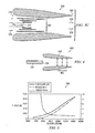
- FIGURE 4 is a schematic of a propulsive jet 400 illustrating testing locations 402 for an exit 404 of a nozzle 406 according to one embodiment of the present invention.
- the testing of the apparatus illustrated in FIGURE 4 illustrates the feasibility of the principles and embodiments discussed above in conjunction with FIGURES 1A through 3C .
- nozzle 406 is placed into an opening of a main body 408 which resembles a venturi tube.
- the sizes of nozzle 406 used in the testing were 0.5-inch diameter, 0.75-inch diameter, 1-inch diameter, and 1.5-inch diameter.
- Locations 402, represented by letters A, B, and C, were 1 inch after (A), at (B), and 1 inch before (C) the narrow point of the venturi's throat.
- an air header was constructed that could use a compressed air line.
- This air header included a PVC tee with plugs on two of the three openings. One plug was tapped for a thermocouple adapter and another plug opposite thereof was tapped for an air line.
- a 1 ⁇ 4-inch male-male adapter and a 3/8 to 1 ⁇ 4-inch adapter were used to mount a 3/8-inch ball valve to the tee.
- a 1 ⁇ 4-inch quick couple was attached through another 3/8 to 1 ⁇ 4-inch adapter to the other end of the ball valve. The compressed air line was then connected to this quick connect.
- a housing was made to hold the air header firmly centered in the main body 408.
- the housing had holes spaced 1 inch apart in its base that was used to align the exit 404 of nozzle 406 of the air header where the main body 408 converged (i.e., the throat), or at a point 1 inch before or 1 inch after that point (locations 402).
- the assembly was mounted on the sled that was attached to parallel rails by a set of linear bearings to reduce friction, and this was mounted to a wind tunnel testing section.
- the measuring equipment included tubing, which was attached at exit 404 of nozzle 406 facing into the airflow and then attached to a U-tube manometer. The other side of the manometer was left open to atmosphere.
- a 0-200 psig pressure gauge was mounted in the PVC tee.
- a thermocouple was mounted in one of the plugs of the PVC tee.
- a Fluke 5311 thermometer was used to collect the readings of the thermocouple.
- a Futek load cell was mounted between the sled and the table.
- a Transducer Techniques TMO-1 amplifier/conditioner module was used to gather readings from the load cell, which were read as voltages by a multimeter.
- the load cell was suitably calibrated by mounting the load cell to a flat plate and then hanging a mass of 2058.3 g from the load cell.
- the load cell has a capacity of 25 pounds so the mass was converted to a fraction of the maximum load possible.
- the proper reading from the amplifier was determined using the maximum voltage output for the amplifier of 8 volts.
- the ambient pressure of the laboratory was measured before each change in diameter of nozzle 406.
- a compressed air hose was coupled to the air header.
- the ball valve was used to vary the velocity exiting the air header. Readings were taken at various air velocities for each of the three positions 402. Readings were also taken at various velocities with only the air header mounted to the sled.
- V 1096.7 ⁇ P ⁇
- the thrust results were plotted versus air velocity for the various configurations used during the testing. Using least squares curve fitting, equations may be obtained to represent both nozzle only thrust and propulsive jet thrust.
- the thrust amplification factor is defined as the ratio of the thrust from the propulsive jet 400 (which includes both the main body 408 and nozzle 406) to the nozzle 406 only. k ⁇ propulsive jet thrust nozzle only thrust
- the propulsive jet 400 performed more poorly than the others.
- the exit 404 was positioned 1 inch before the throat, the two gas streams had widely different velocities.
- the exit 404 was placed in the throat, the two gas streams had more similar velocities.
- This experimental result shows the importance of blending two streams of similar velocity, as predicted by FIGURE 1B .
- FIGURE 5 illustrates a graph of thrust versus velocity for a test in which a 1 ⁇ 2-inch diameter nozzle 406 with its exit 404 1 inch past the throat. This appears to be the best performing configuration of the ones tested.
- the graph 500 illustrates that the amplification factor decreases as velocity increases.
- there was at least a 30% thrust boost (i.e., k 1.3) due to the propulsive jet 400 until a velocity of just over 10,000 ft/min.
- a jet ejector or propulsive jet may have higher efficiencies than traditional jet ejectors and propulsive jets because fluid streams with similar velocities are mixed together.
- Jet ejectors designed and built according to some embodiments of the invention may be used in other heat pump applications, such as air conditioning and distillation may also be used as an efficient vacuum pump.
- Propulsive jets according to some embodiments in the invention may operate quieter, cooler, and more efficiently than current propulsive jets, which is particularly advantageous for military and commercial applications. Tests as illustrated in FIGURES 4 and 5 illustrate significant thrust amplification, especially at low air velocities.
Landscapes
- Engineering & Computer Science (AREA)
- Chemical & Material Sciences (AREA)
- Combustion & Propulsion (AREA)
- Mechanical Engineering (AREA)
- General Engineering & Computer Science (AREA)
- Jet Pumps And Other Pumps (AREA)
Abstract
Description
- The present invention relates generally to the field of fluid flow and, more particularly, to a high-efficiency jet ejector and propulsive jet.
- Energy from fluid flow is used in many applications. For example, jet ejectors, such as steam ejectors, are used as compressors in evaporators. And propulsive jets are used in applications such as jet aircraft, watercraft, missiles, and rockets. As with most mechanical apparatuses that transfer input energy to a useful output energy, efficiency is important; therefore, manufacturers of jet ejectors and propulsive jets are continually searching for more and better techniques to increase efficiency.
- According to one embodiment of the invention, a system for altering fluid flow includes a main body having a first fluid flowing therethrough, a plurality of conduits disposed within the main body to form a plurality of flow paths, and a nozzle directing a second fluid through the innermost conduit. The second fluid has a greater velocity than the first fluid. The second fluid successively entrains the first fluid flowing through the flow paths in such a manner that the portion of the first fluid flowing through the innermost flow path existing between the innermost conduit and its adjacent conduit is entrained first and the portion of the first fluid flowing through the outermost flow path existing between the outermost conduit and the main body is last.
- Another embodiment provides a system for altering fluid flow, comprising:
- a main body having a first fluid flowing therethrough, an inside of the main body resembling a venturi tube having a throat section;
- a plurality of cylindrical conduits concentrically disposed within the main body to form a plurality of annular flow paths, the conduits positioned such that respective exits of the conduits are successively farther downstream moving from the innermost conduit to the outermost conduit, the exit of the outermost conduit positioned proximate the throat section;
- a nozzle directing a second fluid through the innermost conduit, the second fluid having a greater velocity than the first fluid; and
- whereby the second fluid successively entrains the first fluid flowing through the annular flow paths in such a manner that the portion of the first fluid flowing through the innermost annular flow path existing between the innermost conduit and its adjacent conduit is entrained first and the portion of the first fluid flowing through the outermost annular flow path existing between the outermost conduit and the main body is last.
- Another embodiment provides a method for altering fluid flow, comprising:
- flowing a first fluid within the bounds of a main body;
- disposing a plurality of conduits within the main body to form a plurality of flow paths;
- directing a second fluid through the innermost conduit;
- causing the second fluid to have a greater velocity than the first fluid; and
- successively entraining the first fluid flowing through the flow paths in such a manner that the portion of the first fluid flowing through the innermost flow path existing between the innermost conduit and its adjacent conduit is entrained first and the portion of the first fluid flowing through the outermost flow path existing between the outermost conduit and the main body is last.
- Each of the conduits may have an exit, the conduits positioned such that the exits are successively farther downstream moving from the innermost conduit to the outermost conduit.
- Each of the conduits may have an entrance, the conduits preferably positioned such that the entrances are successively farther downstream moving from the innermost conduit to the outermost conduit.
- An inside of the main body may resemble a venturi tube having a throat section. The area of an entrance of the main body may be equal to the area of an exit of the main body. Each of the conduits may have an exit, the exit of the outermost conduit preferably positioned proximate the throat section of the venturi tube.
- The method may further comprise positioning an exit of the outermost conduit proximate the throat section of the venturi tube.
- The conduits may be concentric to one another.
- The conduits may be cylindrical and may have a uniform cross-section, or a cross-section that tapers from an upstream end to a downstream end, or a longitudinal cross section of an airfoil.
- The method may further comprise positioning the conduits such that respective exits of the conduits are successively farther downstream moving from the innermost conduit to the outermost conduit.
- The method may further comprise positioning the conduits such that respective entrances of the conduits are successively farther downstream moving from the innermost conduit to the outermost conduit.
- In the method disposing the plurality of conduits preferably comprises concentrically disposing the conduits.
- The first and second fluids may each be selected from the group consisting of a gas, air, steam, a liquid, water, a solid suspended in a fluid, a mixture, and products of combustion.
- According to one aspect of the present invention there is provided a system for altering fluid flow, comprising:
- a main body having a first fluid flowing therethrough, an inside of the main body resembling a venturi tube having a throat section, an area of an entrance of the main body being greater than an area of an exit of the main body;
- a nozzle disposed within the main body to form an annular flow path between the nozzle and the inside of the main body, an exit of the nozzle positioned proximate the throat section;
- the nozzle directing a second fluid through the main body, the second fluid having a greater velocity than the first fluid; and
- whereby the second fluid successively entrains the first fluid flowing through the annular flow path to increase its velocity and create a mixture of the first and second fluids, the mixture having an outlet pressure at the exit of the main body approximately equal to an inlet pressure of the first fluid at the entrance of the main body.
- Another aspect provides a system for altering fluid flow, comprising:
- a main body having a first fluid flowing therethrough, an inside of the main body resembling a venturi tube having a throat section;
- a nozzle disposed within the main body to form an annular flow path between the nozzle and the inside of the main body, an exit of the nozzle positioned proximate the throat section;
- the nozzle directing a second fluid through the main body, the second fluid having a greater velocity than the first fluid; and
- whereby the second fluid successively entrains the first fluid flowing through the annular flow path to increase its velocity and create a mixture of the first and second fluids, the mixture having an outlet pressure at the exit of the main body greater than an inlet pressure of the first fluid at the entrance of the main body.
- The nozzle is preferably cylindrical and has a uniform cross-section.
- The nozzle may be cylindrical and may have a cross-section that tapers from an upstream end to a downstream end.
- The nozzle may be cylindrical and may have a longitudinal cross section of an airfoil.
- The second fluid may be products of combustion.
- Embodiments of the invention provide a number of technical advantages. Embodiments of the invention may include all, some, or none of these advantages. A jet ejector according to an embodiment of the invention has a higher efficiency than traditional jet ejectors, because gas streams with similar velocities are mixed together. A jet ejector according to one embodiment of the invention may also be used in other heat pump applications, such as air conditioning and distillation. It may also be used as an efficient vacuum pump. A jet engine according to one embodiment of the invention may operate quieter, cooler, and more efficiently than current jet engines, which would be particularly advantageous for military and commercial applications. Tests illustrate significant thrust amplification, especially at low air velocities.
- Other technical advantages are readily apparent to one skilled in the art from the following figures, descriptions and claims. Moreover, while specific advantages have been enumerated above, various embodiments may include all, some, or none of the enumerated advantages.
- For a more complete understanding of the invention, and for further features and advantages, reference is now made to the following description, taken in conjunction with the accompanying drawings, in which:
-
FIGURE 1A is a schematic of the mixing of two fluid streams of dissimilar velocity; -
FIGURE 1B is a graph of efficiency versus phi (φ) for varying psi (ψ) for the mixing of the fluid streams ofFIGURE 1A illustrating that efficiency is high provided that input velocities are similar; -
FIGURE 2 is a schematic of a system for altering fluid flow according to one embodiment of the present invention; -
FIGURE 3A is a schematic of a jet ejector having cylindrical mixing vanes according to one embodiment of the present invention; -
FIGURE 3B is a schematic of a jet ejector having airfoil mixing vanes according to one embodiment of the present invention; -
FIGURE 3C is a schematic of a propulsive jet having tapered conduits according to one embodiment of the present invention; -
FIGURE 4 is a schematic of a jet ejector illustrating testing locations for the exit of a nozzle according to one embodiment of the present invention; and -
FIGURE 5 is a graph of thrust versus velocity for a test in which a ½-inch diameter nozzle with its exit 1 inch past the jet ejector convergence was utilized according to one embodiment of the present invention. -
FIGURE 1A is a schematic of the mixing of a firstfluid stream 100 and a secondfluid stream 102 to create a thirdfluid stream 104. In the illustrated embodiment, firstfluid stream 100 has a lower velocity than secondfluid stream 102. Firstfluid stream 100 increases in velocity secondfluid stream 102 decreases in velocity during the mixing. A mass balance yields:
- Assuming frictionless mixing, a momentum balance yields:

- Substituting Equation 1 into
Equation 2 yields:
- Solving for v 3:

- The following dimensionless group is defined:

- Substituting Equation 5 into
Equation 4 gives:
- The following dimensionless group is defmed:

- Substituting Equation 7 into
Equation 6 gives:
- The efficiency of the mixing process illustrated by
FIGURE 1A is defined as follows:

- The ratio m 1/ m 2 can be expressed in terms of ϕ:

- Substituting Equation 11 into Equation 10:

- Substituting
Equation 8 into Equation 12:
-
FIGURE 1B is a graph ofefficiency 106 versus phi (φ) 108 for varying psi (ψ) 110 for the mixing of first and second fluid streams 100, 102 ofFIGURE 1A illustrating that efficiency is high provided that input velocities are similar. At high ψ, the efficiency is high regardless of φ. At low ψ, the efficiency depends more strongly on φ. An important point is that the efficiency is high provided the input velocities are similar. In a steam ejector application, this may be accomplished by mixing the motive steam and propelled steam in stages. -
FIGURE 2 is a schematic of asystem 200 for altering fluid flow in accordance with one embodiment of the present invention and utilizing the principles illustrated above in conjunction withFIGURES 1A and 1B . In the illustrated embodiment,system 200 resembles a jet ejector; however,system 200 may also be a propulsive jet or other suitable systems that mix two or more streams of fluid. For clarity of description purposes, the jet ejector illustrated inFIGURE 2 is assumed to have circular elements; however, the present invention contemplates the elements having any suitable shape in any suitable size. In addition, for clarity of description purposes, the upstream end ofmain body 202 is indicated byreference numeral 230 and the downstream end is indicated byreference numeral 232. - In the illustrated embodiment,
system 200 includes amain body 202 having afirst fluid 203 flowing therethrough, a plurality ofconduits main body 202 to form a plurality offlow paths nozzle 208 directing asecond fluid 209 through theinnermost conduit 204c. Althoughfirst fluid 203 andsecond fluid 209 may have any suitable velocity,second fluid 209 has a greater velocity thanfirst fluid 203 according to the teachings of the present invention. Thesecond fluid 209 may be considered a motive fluid whereasfirst fluid 203 may be considered the propelled fluid. Depending on the application ofsystem 200,first fluid 203 andsecond fluid 209 may be any suitable fluids, such as a gas, a liquid, air, water, steam, products of combustion, a solid suspended in a fluid, or any suitable combination thereof. -
Main body 202, which may be formed from any suitable material, includes aninside surface 210 that, in one embodiment, resembles a venturi tube. As such, inside 210 includes a convergingsection 211, athroat section 212, and a divergingsection 213 that may have any suitable lengths and any suitable diameters. In an embodiment wheresystem 200 acts as a propulsive jet, an entrance 218 ofmain body 202 has a greater diameter than an exit 220 ofmain body 202. In an embodiment wheresystem 200 acts as a jet ejector, entrance 218 may have any suitable diameter with respect to exit 220, although the inlet pressure will be less than the outlet pressure. Although the contour of the convergingsection 211 illustrated inFIGURE 2 includes a rounded entrance followed by a straight section, it may be rounded only, straight only, or any other suitable converging geometry. Thethroat section 212 and divergingsection 213 are illustrated inFIGURE 2 as being relatively straight; however, the present invention contemplates thethroat section 212 and divergingsection 213 to have any suitable contour. - Conduits 204 are disposed within
main body 202 and coupled tomain body 202 and to each other via any suitable method. In the illustrated embodiment, conduits 204 are concentric to one another; however, conduits 204 may be non-concentric, or in the case of non-cylindrical conduits, may have any suitable spacing. In addition, conduits 204 may have any suitable length and any suitable thickness. Assuming conduits 204 are cylindrical, flow paths 206 form annular flow paths forfirst fluid 203. - In one embodiment, exits 214 of conduits 204 are successively farther downstream moving from the
innermost conduit 204c to theoutermost conduit 204a. In other words, theexit 214c ofinnermost conduit 204c is further upstream from theexit 214b ofconduit 204b, which in turn is further upstream than exit 214a ofconduit 204a. In a particular embodiment, exit 214a ofconduit 204a isproximate throat section 212 ofmain body 202. The positioning of exit 214a may depend on any number of factors, such as the type offirst fluid 203, the type ofsecond fluid 209, the velocities offirst fluid 203 and/orsecond fluid 209, the lengths of conduits 204, the area offlow paths 206a, or other suitable factors. - In the illustrated embodiment, the entrances 216 of conduits 204 are successively farther downstream moving from
innermost conduit 204c to theoutermost conduit 204a. In other words, anentrance 216c ofconduit 204c is farther upstream thanentrance 216b ofconduit 204b, which in turn is farther upstream thanentrance 216a ofconduit 204a. However, the present invention contemplates entrances 216 of conduits 204 being in any suitable position. -
Nozzle 208 may be any suitable conduit that is operable to injectsecond fluid 209 into theinnermost conduit 204c. In one embodiment,nozzle 208 injects a high-velocity, high-pressure fluid intoinnermost conduit 204c. In operation,second fluid 209 successively entrainsfirst fluid 203 flowing through flow paths 206 as follows: the portion offirst fluid 203 flowing through flow path 206c is entrained bysecond fluid 209 first, followed by the portion offirst fluid 203 flowing throughflow path 206b, followed by the portion offirst fluid 203 flowing throughflow path 206a. In this manner,second fluid 209 accelerates the fluid flowing through flow path 206c and the combination of those two fluids entrains and accelerate the fluid flowing throughflow path 206b, and the combination of those fluids entrains and accelerate the fluid flowing throughflow path 206a. Thus, because the fluids that are being mixed together are more closely matched in velocity, the efficiency improves, as shown to be the case above in conjunction withFIGURES 1A and 1B . -
FIGURE 3A is a schematic of ajet ejector 300 in which conduits 204 representcylindrical mixing vanes 302, each having a uniform cross-section. In this embodiment, the propelled fluid, as indicated byreference numeral 304, is accelerated to sonic velocity at the throat. Similar to the embodiment illustrated inFIGURE 2 , mixingvanes 302 may have any suitable length and any suitable diameter. Also illustrated inFIGURE 3A is anozzle 305 having anend 306 shaped as a venturi tube. This merely illustrates that the nozzle utilized may be any suitable nozzle operable to inject a fluid into the innermost conduit. -
FIGURE 3B is a schematic of ajet ejector 310 havingairfoil mixing vanes 312 according to one embodiment of the present invention. As illustrated,airfoil mixing vanes 312 have a longitudinal cross-section that resembles an airfoil. This embodiment facilitates less turbulence and friction within the main body ofjet ejector 310. - The tapered conduits 204 illustrated in
FIGURE 2 , the mixingvanes 302 illustrated inFIGURE 3A , and theairfoil mixing vanes 312 illustrated inFIGURE 3B may be utilized in any suitable combination within a particular jet ejector in order to obtain the desired result of fluid flow. This may depend upon many factors, such as the velocity of the motive fluid and propelled fluid, the size and shape of the main body and conduits disposed therein, and the type of fluids utilized for the motive and propelled fluid. -
FIGURE 3C is a schematic of apropulsive jet 320 having taperedconduits 322 according to one embodiment of the present invention. As described above, the teachings of the present invention may be utilized in the context of a propulsive jet, which may be used to propel vehicles, such as aircraft, rockets, missiles, and ships. In one embodiment, high-velocity motive fluid, as indicated byreference numeral 324, is mixed with low-velocity inlet fluid, as indicated by reference numeral 326. The mixture, as indicated byreference numeral 328, exits at medium velocity. Because the cross-sectional area of theoutlet 329 ofpropulsive jet 320 is less than the cross-sectional area of aninlet 330 ofpropulsive jet 320, the outlet velocity is higher than the inlet velocity. By conservation of momentum, there is a net forward thrust exerted onpropulsive jet 320. -
Motive fluid 324 may be produced by any suitable number of methods. For example, it could be the exhaust of a conventional jet engine, the exhaust of a conventional rocket, a high-velocity stream of air produced by forcing compressed air through a nozzle, or a high-velocity stream of water produced by forcing high-pressure water through a nozzle. In the illustrated embodiment,motive fluid 324 exits as slightly supersonic velocity and mixes with the sonic fluid in theinnermost conduit 322. Thereafter the mixture blends with subsonic fluid from the remainingconduits 322. As in the case of the jet ejectors illustrated inFIGURES 2 ,3A and 3B , propulsive jets, such aspropulsive jet 320, may also utilize any suitable combination of cylindrical mixing vanes, airfoil mixing vanes, and tapered conduits. -
FIGURE 4 is a schematic of apropulsive jet 400 illustratingtesting locations 402 for anexit 404 of anozzle 406 according to one embodiment of the present invention. The testing of the apparatus illustrated inFIGURE 4 illustrates the feasibility of the principles and embodiments discussed above in conjunction withFIGURES 1A through 3C . - In the illustrated embodiment,
nozzle 406 is placed into an opening of amain body 408 which resembles a venturi tube. The sizes ofnozzle 406 used in the testing were 0.5-inch diameter, 0.75-inch diameter, 1-inch diameter, and 1.5-inch diameter.Locations 402, represented by letters A, B, and C, were 1 inch after (A), at (B), and 1 inch before (C) the narrow point of the venturi's throat. - In the experimental setup (not illustrated), an air header was constructed that could use a compressed air line. This air header included a PVC tee with plugs on two of the three openings. One plug was tapped for a thermocouple adapter and another plug opposite thereof was tapped for an air line. A ¼-inch male-male adapter and a 3/8 to ¼-inch adapter were used to mount a 3/8-inch ball valve to the tee. A ¼-inch quick couple was attached through another 3/8 to ¼-inch adapter to the other end of the ball valve. The compressed air line was then connected to this quick connect.
- A housing was made to hold the air header firmly centered in the
main body 408. The housing had holes spaced 1 inch apart in its base that was used to align theexit 404 ofnozzle 406 of the air header where themain body 408 converged (i.e., the throat), or at a point 1 inch before or 1 inch after that point (locations 402). The assembly was mounted on the sled that was attached to parallel rails by a set of linear bearings to reduce friction, and this was mounted to a wind tunnel testing section. - The measuring equipment included tubing, which was attached at
exit 404 ofnozzle 406 facing into the airflow and then attached to a U-tube manometer. The other side of the manometer was left open to atmosphere. A 0-200 psig pressure gauge was mounted in the PVC tee. As mentioned above, a thermocouple was mounted in one of the plugs of the PVC tee. A Fluke 5311 thermometer was used to collect the readings of the thermocouple. A Futek load cell was mounted between the sled and the table. A Transducer Techniques TMO-1 amplifier/conditioner module was used to gather readings from the load cell, which were read as voltages by a multimeter. - The load cell was suitably calibrated by mounting the load cell to a flat plate and then hanging a mass of 2058.3 g from the load cell. The load cell has a capacity of 25 pounds so the mass was converted to a fraction of the maximum load possible. The proper reading from the amplifier was determined using the maximum voltage output for the amplifier of 8 volts.


- The gain pot was adjusted on the amplifier until the multimeter reading matched the calculated voltage reading. With the mass removed, the balance pot was readjusted to make the multimeter read 0 volts again. After this calibration, the amplifier would read 0 volts with no load on the load cell and 8 volts with a 25-pound load on the load cell. A line connecting these two points could be used to convert the multimeter readings to thrust.

To ensure that this equation was accurate, several other masses were measured using the load cell and compared to the graph of this equation. - With respect to testing, the ambient pressure of the laboratory was measured before each change in diameter of
nozzle 406. With the ball valve closed, a compressed air hose was coupled to the air header. The ball valve was used to vary the velocity exiting the air header. Readings were taken at various air velocities for each of the threepositions 402. Readings were also taken at various velocities with only the air header mounted to the sled. - The motive air density can be determined using the following equation:

where - ρ = Dry air density (lbm/ft3)
- P = Motive air pressure (in Hg)
- Pa = Ambient pressure (in Hg)
- T = Absolute air temperature (°R)
- Once the air density is known, the measured pressure drops can be used to calculate the air velocity:

where - V = Air velocity (ft/min)
- P = Motive air pressure (in H2O)
- The thrust results were plotted versus air velocity for the various configurations used during the testing. Using least squares curve fitting, equations may be obtained to represent both nozzle only thrust and propulsive jet thrust. The thrust amplification factor is defined as the ratio of the thrust from the propulsive jet 400 (which includes both the
main body 408 and nozzle 406) to thenozzle 406 only.
For each of thenozzle 406 diameters, when theexit 404 was positioned 1 inch before the throat, thepropulsive jet 400 performed more poorly than the others. When theexit 404 was positioned 1 inch before the throat, the two gas streams had widely different velocities. In contrast, when theexit 404 was placed in the throat, the two gas streams had more similar velocities. This experimental result shows the importance of blending two streams of similar velocity, as predicted byFIGURE 1B . -
FIGURE 5 illustrates a graph of thrust versus velocity for a test in which a ½-inch diameter nozzle 406 with itsexit 404 1 inch past the throat. This appears to be the best performing configuration of the ones tested. Thegraph 500 illustrates that the amplification factor decreases as velocity increases. In one embodiment, there was at least a 30% thrust boost (i.e., k=1.3) due to thepropulsive jet 400 until a velocity of just over 10,000 ft/min. - Thus, according to some embodiments of the invention, a jet ejector or propulsive jet may have higher efficiencies than traditional jet ejectors and propulsive jets because fluid streams with similar velocities are mixed together. Jet ejectors designed and built according to some embodiments of the invention may be used in other heat pump applications, such as air conditioning and distillation may also be used as an efficient vacuum pump. Propulsive jets according to some embodiments in the invention may operate quieter, cooler, and more efficiently than current propulsive jets, which is particularly advantageous for military and commercial applications. Tests as illustrated in
FIGURES 4 and 5 illustrate significant thrust amplification, especially at low air velocities. - Although embodiments of the invention and their advantages are described in detail, a person skilled in the art could make various alterations, additions, and omissions without departing from the spirit and scope of the present invention.
Claims (6)
- A system for altering fluid flow, comprising:a main body having a first fluid flowing therethrough, wherein the inside of the main body is a venturi tube having an inlet, a throat section, and an outlet, wherein the area of inlet is at least greater than the area of the outlet of the main body;a nozzle disposed within the main body to form an annular flow path between the nozzle and the inside of the main body, at least one exit of the nozzle positioned proximate the throat section;the nozzle directing a second fluid through the main body, the second fluid having a greater velocity than the first fluid; andwhereby the second fluid successively entrains the first fluid flowing through the annular flow path to increase its velocity and create a mixture of the first and second fluids, the mixture having an outlet pressure at the exit of the main body at least equal to an inlet pressure of the first fluid at the entrance of the main body.
- The system of Claim 1, wherein the nozzle is cylindrical and has a uniform cross-section.
- The system of Claims 1 and 2, wherein the nozzle is cylindrical and has a cross-section that tapers from an upstream end to a downstream end.
- The system of Claim 1, wherein the nozzle is cylindrical and has a longitudinal cross section of an airfoil.
- The system of Claim 1, wherein the second fluid is products of combustion.
- The system of Claim 1, wherein the outlet pressure is at least greater than the inlet pressure of the main body.
Applications Claiming Priority (3)
| Application Number | Priority Date | Filing Date | Title |
|---|---|---|---|
| US43985103P | 2003-01-13 | 2003-01-13 | |
| US10/755,570 US7780099B2 (en) | 2003-01-13 | 2004-01-12 | High-efficiency jet ejector and propulsive jet |
| EP04701834A EP1590564A1 (en) | 2003-01-13 | 2004-01-13 | Jet ejector and method of altering fluid flow |
Related Parent Applications (1)
| Application Number | Title | Priority Date | Filing Date |
|---|---|---|---|
| EP04701834.6 Division | 2004-01-13 |
Publications (2)
| Publication Number | Publication Date |
|---|---|
| EP2264296A2 true EP2264296A2 (en) | 2010-12-22 |
| EP2264296A3 EP2264296A3 (en) | 2011-12-07 |
Family
ID=32718123
Family Applications (2)
| Application Number | Title | Priority Date | Filing Date |
|---|---|---|---|
| EP04701834A Withdrawn EP1590564A1 (en) | 2003-01-13 | 2004-01-13 | Jet ejector and method of altering fluid flow |
| EP10011400A Withdrawn EP2264296A3 (en) | 2003-01-13 | 2004-01-13 | System for altering fluid flow |
Family Applications Before (1)
| Application Number | Title | Priority Date | Filing Date |
|---|---|---|---|
| EP04701834A Withdrawn EP1590564A1 (en) | 2003-01-13 | 2004-01-13 | Jet ejector and method of altering fluid flow |
Country Status (3)
| Country | Link |
|---|---|
| US (1) | US7780099B2 (en) |
| EP (2) | EP1590564A1 (en) |
| WO (1) | WO2004063549A1 (en) |
Families Citing this family (2)
| Publication number | Priority date | Publication date | Assignee | Title |
|---|---|---|---|---|
| US8783585B2 (en) * | 2009-05-20 | 2014-07-22 | General Electric Company | Methods and systems for mixing reactor feed |
| ZA201206018B (en) * | 2011-12-20 | 2013-05-29 | Pyro Res And Dev (Pty) Ltd | A propulsion device |
Family Cites Families (16)
| Publication number | Priority date | Publication date | Assignee | Title |
|---|---|---|---|---|
| DE612362C (en) | 1935-04-18 | E H Gustav De Grahl Dr Ing | Rocket with the air duct surrounding the combustion chamber | |
| US1375601A (en) | 1919-03-27 | 1921-04-19 | Morize Ernest | Propelling device for use on vehicles, marine vessels, or aircraft |
| FR522163A (en) | 1919-10-23 | 1921-07-27 | Henri Fabrice Melot | Method and devices for compressing oxidizer and fuel for horn thrusters |
| FR523427A (en) | 1920-01-19 | 1921-08-18 | Henri Fabrice Melot | Method and devices for supplying the oxidant to the horn thrusters |
| US1839527A (en) * | 1928-06-07 | 1932-01-05 | Albert H Bates | Hydrocarbon burner |
| DE637043C (en) | 1934-05-25 | 1936-10-19 | E H Gustav De Grahl Dr Ing | Missile with air ducts surrounding the combustion chamber |
| DE738239C (en) | 1934-11-27 | 1943-08-06 | Hubert Korndoerfer | Recoil drive device |
| FR800835A (en) | 1935-03-13 | 1936-07-20 | Method and devices for producing oxidizer under high pressure for heat engines | |
| GB584254A (en) * | 1943-04-14 | 1947-01-10 | Likuvag Ag | Improvements in or relating to exhaust nozzles more especially for internal combustion engines |
| US2547936A (en) | 1944-11-17 | 1951-04-10 | Harlow B Grow | Ducted rocket propulsion means for aircraft |
| US2787120A (en) | 1950-08-05 | 1957-04-02 | Leduc Rene | Plural annular coaxial combustion chambers |
| FR1037907A (en) | 1951-05-30 | 1953-09-23 | Snecma | Jet thruster |
| US2663142A (en) | 1951-12-20 | 1953-12-22 | Wilson Walter Hobart | Thermojet engine |
| US3221497A (en) | 1962-06-29 | 1965-12-07 | Jr Ernest E Forbes | Ramjet propulsion system |
| US3338051A (en) | 1965-05-28 | 1967-08-29 | United Aircraft Corp | High velocity ram induction burner |
| US4372110A (en) * | 1976-02-13 | 1983-02-08 | Nasa | Noise suppressor for turbo fan jet engines |
-
2004
- 2004-01-12 US US10/755,570 patent/US7780099B2/en not_active Expired - Fee Related
- 2004-01-13 WO PCT/US2004/000874 patent/WO2004063549A1/en not_active Ceased
- 2004-01-13 EP EP04701834A patent/EP1590564A1/en not_active Withdrawn
- 2004-01-13 EP EP10011400A patent/EP2264296A3/en not_active Withdrawn
Non-Patent Citations (1)
| Title |
|---|
| None |
Also Published As
| Publication number | Publication date |
|---|---|
| EP1590564A1 (en) | 2005-11-02 |
| EP2264296A3 (en) | 2011-12-07 |
| US20050178856A1 (en) | 2005-08-18 |
| WO2004063549A1 (en) | 2004-07-29 |
| US7780099B2 (en) | 2010-08-24 |
Similar Documents
| Publication | Publication Date | Title |
|---|---|---|
| US5880378A (en) | Critical flow venturi with variable and continuous range | |
| EP2264296A2 (en) | System for altering fluid flow | |
| Isaac et al. | Experimental study of the interaction of multiple jets with a cross flow | |
| HK1148332A (en) | System for altering fluid flow | |
| US20210003458A1 (en) | Method and system for measuring temperature in a gas turbine engine | |
| Ursino et al. | Second-Generation Development of a Radial Rotating Detonation Engine | |
| Zakharov et al. | Computational and experimental study of the influence of the shape of nozzle supersonic part on the flow structure in the gas-dynamic flow path of a model high-altitude test facility | |
| BATSON et al. | Swirling flow through a nozzle | |
| Grannan et al. | Small Turbojet Altitude Test Facility with Two Stage Turbocharger Inlet Air Cooling | |
| Peters et al. | An evaluation of jet simulation parameters for nozzle/afterbody testing at transonic Mach numbers | |
| USRE28090E (en) | Diffuser by | |
| Petersen et al. | Experimental investigation of supersonic-primary dissimilar-fluid ejectors | |
| Alperin et al. | Recent development of a jet-diffuser ejector | |
| Brooks | A method for more reproducible burning rate determination | |
| US3035439A (en) | Hypersonic wind tunnel test section | |
| Kato et al. | Experimental study of combined cycle engine combustor in scramjet mode | |
| Lineberry et al. | Characterization of cold flow non-axisymmetric ejectors | |
| CN114414192B (en) | Hydraulic performance testing device and method for water jet propeller inlet channel | |
| Ueda et al. | Subsonic flight experiments of ejector-rocket using hybrid-rocket CAMUI | |
| STEPHENS et al. | Geometry effects in second throat annular steam ejectors | |
| Cheng et al. | Experimental study on optimization parameters of a supersonic jet ejector thrust augmentor. | |
| Bottenheim et al. | The Effect of an entraining diffuser on the performance of circular-to-slot exhaust ducts with a 90 degree bend | |
| Bakhtiyarov | Topic FM-17: Compressible Fluid Flow—Isentropic Flow Through Converging and Diverging Nozzles | |
| YOST et al. | Small, high-performance engine component technology status | |
| Campbell et al. | Test Results of a VTOL Propulsion Concept Utilizing aTurbofan Powered Augmentor |
Legal Events
| Date | Code | Title | Description |
|---|---|---|---|
| PUAI | Public reference made under article 153(3) epc to a published international application that has entered the european phase |
Free format text: ORIGINAL CODE: 0009012 |
|
| AC | Divisional application: reference to earlier application |
Ref document number: 1590564 Country of ref document: EP Kind code of ref document: P |
|
| AK | Designated contracting states |
Kind code of ref document: A2 Designated state(s): AT BE BG CH CY CZ DE DK EE ES FI FR GB GR HU IE IT LI LU MC NL PT RO SE SI SK TR |
|
| RIN1 | Information on inventor provided before grant (corrected) |
Inventor name: HOTZAPPLE, MARK T. Inventor name: REDINIOTIS, OTHON |
|
| REG | Reference to a national code |
Ref country code: HK Ref legal event code: DE Ref document number: 1148332 Country of ref document: HK |
|
| PUAL | Search report despatched |
Free format text: ORIGINAL CODE: 0009013 |
|
| AK | Designated contracting states |
Kind code of ref document: A3 Designated state(s): AT BE BG CH CY CZ DE DK EE ES FI FR GB GR HU IE IT LI LU MC NL PT RO SE SI SK TR |
|
| RIC1 | Information provided on ipc code assigned before grant |
Ipc: F02C 3/32 20060101AFI20111028BHEP Ipc: F02K 7/12 20060101ALI20111028BHEP |
|
| STAA | Information on the status of an ep patent application or granted ep patent |
Free format text: STATUS: THE APPLICATION IS DEEMED TO BE WITHDRAWN |
|
| 18D | Application deemed to be withdrawn |
Effective date: 20120609 |
|
| REG | Reference to a national code |
Ref country code: HK Ref legal event code: WD Ref document number: 1148332 Country of ref document: HK |