EP2263919A1 - Automobile front body structure - Google Patents
Automobile front body structure Download PDFInfo
- Publication number
- EP2263919A1 EP2263919A1 EP10165473A EP10165473A EP2263919A1 EP 2263919 A1 EP2263919 A1 EP 2263919A1 EP 10165473 A EP10165473 A EP 10165473A EP 10165473 A EP10165473 A EP 10165473A EP 2263919 A1 EP2263919 A1 EP 2263919A1
- Authority
- EP
- European Patent Office
- Prior art keywords
- plate member
- rigidity plate
- low
- rigidity
- wall
- Prior art date
- Legal status (The legal status is an assumption and is not a legal conclusion. Google has not performed a legal analysis and makes no representation as to the accuracy of the status listed.)
- Granted
Links
Images


Classifications
-
- B—PERFORMING OPERATIONS; TRANSPORTING
- B62—LAND VEHICLES FOR TRAVELLING OTHERWISE THAN ON RAILS
- B62D—MOTOR VEHICLES; TRAILERS
- B62D25/00—Superstructure or monocoque structure sub-units; Parts or details thereof not otherwise provided for
- B62D25/08—Front or rear portions
- B62D25/082—Engine compartments
-
- B—PERFORMING OPERATIONS; TRANSPORTING
- B60—VEHICLES IN GENERAL
- B60D—VEHICLE CONNECTIONS
- B60D1/00—Traction couplings; Hitches; Draw-gear; Towing devices
- B60D1/01—Traction couplings or hitches characterised by their type
- B60D1/04—Hook or hook-and-hasp couplings
-
- B—PERFORMING OPERATIONS; TRANSPORTING
- B60—VEHICLES IN GENERAL
- B60D—VEHICLE CONNECTIONS
- B60D1/00—Traction couplings; Hitches; Draw-gear; Towing devices
- B60D1/48—Traction couplings; Hitches; Draw-gear; Towing devices characterised by the mounting
- B60D1/485—Traction couplings; Hitches; Draw-gear; Towing devices characterised by the mounting mounted by means of transversal members attached to the frame of a vehicle
-
- B—PERFORMING OPERATIONS; TRANSPORTING
- B60—VEHICLES IN GENERAL
- B60D—VEHICLE CONNECTIONS
- B60D1/00—Traction couplings; Hitches; Draw-gear; Towing devices
- B60D1/48—Traction couplings; Hitches; Draw-gear; Towing devices characterised by the mounting
- B60D1/488—Traction couplings; Hitches; Draw-gear; Towing devices characterised by the mounting mounted directly to the chassis of the towing vehicle
-
- B—PERFORMING OPERATIONS; TRANSPORTING
- B60—VEHICLES IN GENERAL
- B60D—VEHICLE CONNECTIONS
- B60D1/00—Traction couplings; Hitches; Draw-gear; Towing devices
- B60D1/48—Traction couplings; Hitches; Draw-gear; Towing devices characterised by the mounting
- B60D1/52—Traction couplings; Hitches; Draw-gear; Towing devices characterised by the mounting removably mounted
-
- B—PERFORMING OPERATIONS; TRANSPORTING
- B60—VEHICLES IN GENERAL
- B60D—VEHICLE CONNECTIONS
- B60D1/00—Traction couplings; Hitches; Draw-gear; Towing devices
- B60D1/48—Traction couplings; Hitches; Draw-gear; Towing devices characterised by the mounting
- B60D1/56—Traction couplings; Hitches; Draw-gear; Towing devices characterised by the mounting securing to the vehicle bumper
- B60D1/565—Traction couplings; Hitches; Draw-gear; Towing devices characterised by the mounting securing to the vehicle bumper having an eyelet
-
- B—PERFORMING OPERATIONS; TRANSPORTING
- B60—VEHICLES IN GENERAL
- B60D—VEHICLE CONNECTIONS
- B60D3/00—Fittings to facilitate pushing
-
- B—PERFORMING OPERATIONS; TRANSPORTING
- B60—VEHICLES IN GENERAL
- B60R—VEHICLES, VEHICLE FITTINGS, OR VEHICLE PARTS, NOT OTHERWISE PROVIDED FOR
- B60R19/00—Wheel guards; Radiator guards, e.g. grilles; Obstruction removers; Fittings damping bouncing force in collisions
- B60R19/02—Bumpers, i.e. impact receiving or absorbing members for protecting vehicles or fending off blows from other vehicles or objects
- B60R19/24—Arrangements for mounting bumpers on vehicles
- B60R19/26—Arrangements for mounting bumpers on vehicles comprising yieldable mounting means
-
- B—PERFORMING OPERATIONS; TRANSPORTING
- B60—VEHICLES IN GENERAL
- B60R—VEHICLES, VEHICLE FITTINGS, OR VEHICLE PARTS, NOT OTHERWISE PROVIDED FOR
- B60R19/00—Wheel guards; Radiator guards, e.g. grilles; Obstruction removers; Fittings damping bouncing force in collisions
- B60R19/02—Bumpers, i.e. impact receiving or absorbing members for protecting vehicles or fending off blows from other vehicles or objects
- B60R19/24—Arrangements for mounting bumpers on vehicles
- B60R19/26—Arrangements for mounting bumpers on vehicles comprising yieldable mounting means
- B60R19/34—Arrangements for mounting bumpers on vehicles comprising yieldable mounting means destroyed upon impact, e.g. one-shot type
-
- B—PERFORMING OPERATIONS; TRANSPORTING
- B62—LAND VEHICLES FOR TRAVELLING OTHERWISE THAN ON RAILS
- B62D—MOTOR VEHICLES; TRAILERS
- B62D21/00—Understructures, i.e. chassis frame on which a vehicle body may be mounted
- B62D21/15—Understructures, i.e. chassis frame on which a vehicle body may be mounted having impact absorbing means, e.g. a frame designed to permanently or temporarily change shape or dimension upon impact with another body
- B62D21/152—Front or rear frames
Definitions
- the present invention relates to a vehicle front body structure having a bumper beam extension disposed between a bumper beam and a front side frame for absorbing an impact applied to a front part of the vehicle body.
- Vehicle front body structures of the type having a bumper beam supported at the front end of a front side frame via a bumper beam extension are known and used heretofore.
- the known vehicle front body structures are generally designed such that when an own vehicle is subjected to a light or low-speed collision with an oncoming vehicle, the bumper beam extension yields to absorb a collision impact to thereby protect a main frameworks including the front side frame against deformation or damage.
- One example of the known vehicle front body structures is disclosed in Japanese Patent Application Laid-Open Publication No. 2007-190964 ( JP-A 2007-190964 ).
- the disclosed vehicle front body structure includes a front side frame extending in a longitudinal direction of the vehicle body, a front pillar disposed above a rear part of the front side frame, and a lower side frame extending from a bottom end of the front pillar toward the front of the vehicle body and disposed on a lateral outer side of the front side frame.
- a front end of the front side frame and a front end of the lower side frame are connected with each other, and a bumper beam is supported at the thus connected front ends of the front side frame and the lower side frame.
- the vehicle front body structure shown in JP-A 2007-190964 is particularly suitable for use in sedan or saloon cars, which can provide a relatively large space between the front end of the front side frame and a bumper face for installation of a bumper beam extension or an impact absorber.
- a bumper beam extension or an impact absorber for installation of a bumper beam extension or an impact absorber.
- only a small space is available in a longitudinal direction of the vehicle between the front end of a front side frame and a bumper face for the purpose of installation of a safety plate bonded to the front end of a bumper beam, or of an impact absorbing structure disposed between the front end of the front side frame and the bumper face.
- the front body structure shown in JP 2007-190964A cannot be used in the light vehicles without reconstruction.
- the bumper beam extension used in the vehicle front body structure disclosed in JP-A 2007-190964 is designed to produce an unyielding portion, which remains unyielding when the bumper beam extension is subjected to a collision with an oncoming vehicle. Due to the provision of the unyielding portion, the disclosed bumper beam extension requires a relatively large space in the longitudinal direction of the vehicle for installation thereof. It is, therefore, practically impossible for the disclosed bumper beam extension to be installed in a relatively small space and, even if installation of such bumper beam extension were made, a sufficient impact-absorbing stroke would not be attainable.
- An alternative attempt to provide an impact absorber in the light vehicles may include reduction of the rigidity of the bumper beam, however, the attempted bumper beam of reduced rigidity will fail to perform a load-transmitting function, which is required when an offset collision occurs, in order to reduce deformation of a crashed side of the vehicle.
- the present invention seeks to provide a vehicle front body structure, which is capable of performing a sufficient impact energy absorbing function even when it is employed in a vehicle that is hard to provide a large space between the front end of a front side frame and a bumper face.
- a vehicle front body structure including right and left side frames extending in a longitudinal direction of the vehicle body, and a high-rigidity plate member disposed forwardly of front ends of the right and left side frames and extending in a width direction of the vehicle body, characterized in that the high-rigidity plate member is connected via a low-rigidity plate member to the front end of each of the right and left side frames, the low-rigidity plate member having a rigidity smaller than a rigidity of the high-rigidity plate member, wherein the low-rigidity plate member includes a transverse wall connected to the high-rigidity plate member and extending in the width direction of the vehicle body, and a longitudinal wall extending from the transverse wall in the longitudinal direction of the vehicle body toward the front end of the right or left side frame in such a manner as to form a bent portion between the transverse wall and the vertical wall and connected to the front end of the right or left side frame, and wherein when the high-rigidity plate member is connected
- the low-rigidity plate member solely undergoes deformation or yielding to thereby absorb the collision load while the high-rigidity plate member remains undeformed.
- the low-rigidity plate member starts distorting at the bent portion to cause the longitudinal wall to tilt down in a lateral inward direction of the vehicle body as the bent portion moves in the same direction as the tilting movement of the longitudinal wall. With this tiling movement of the longitudinal wall, the collision load can be absorbed.
- the longitudinal wall of the low-rigidity plate member is yieldable in its entirety without leaving an unyielding portion when the low-rigidity plate member is subjected to the collision load. Using such longitudinal wall enables a reduction in size of the low-rigidity plate member in the longitudinal direction of the vehicle body.
- the low-rigidity plate member (bumper beam extension) and the high-rigidity plate member (bumper beam) used in combination are able to perform a sufficiently large impact energy function when used in light vehicles that can provide only a relatively small installation space defined between the front ends of the right and left side frames and a bumper face disposed forwardly of the high-rigidity plate member (bumper beam).
- the longitudinal wall of the low-rigidity plate member extends at an obtuse angle to the transverse wall such that a front end of the longitudinal wall is disposed inwardly of a rear end of the longitudinal wall as viewed in the width direction of the vehicle body.
- a collision load applied to the high-rigidity plate member at right angles to the latter will cause the vertical wall to tilt in the lateral inward direction of the vehicle body.
- the collision load is transmitted via the high-rigidity plate member (bumper beam) to the right and left side frames.
- This arrangement is particularly advantageous when an offset head-on collision occurs because the collision load can be efficiently distributed via the high-rigidity plate member to the right and left side frames. As a result, the impact absorbing efficiency of the vehicle front body structure increases sufficiently.
- each of the right and left side frames has an end flange extending from the front end thereof in a lateral outward direction of the vehicle body
- the low-rigidity plate member further has an end flange extending from an end of the vertical wall in a lateral outward direction of the vehicle body, the end flange of the low-rigidity plate member being attached to the end flange of the right or left side frame.
- the low-rigidity plate member is connected to the right or left side frame on a lateral outer side thereof, when the high-rigidity plate member is subjected to a large collision load which may occur at a collision with a hard object such as an oncoming vehicle, the high-rigidity plate member while being displaced backwards during collision is supported by the side frames, and the large collision load can thus be born by the side frames. Furthermore, by connecting the low-rigidity plate member and the right or left side frame on the lateral outer side of the side frame, it is possible to maintain a necessary area of the transverse wall even when the vertical wall is arranged at the obtuse angle to the transverse wall. This arrangement allows the transverse wall to have a tow-hook insertion through-hole.
- the transverse wall of the low-rigidity plate member has a U-shape or a hat-like shape in cross section.
- the transverse wall having such cross-sectional shape can retain a sufficient degree of rigidity, which is large enough to ensure that the low-rigidity plate member starts distorting at the bent portion to cause tilting of the longitudinal wall in the lateral inward direction of the vehicle body when a collision load acts on the high-rigidity plate member.
- the low-rigidity plate member is removably connected to the high-rigidity plate member.
- a relatively small collision load which may occur during a collision with a relatively soft object such as a pedestrian
- only the low-rigidity plate member of the vehicle front body structure undergoes plastic deformation or collapsing for absorbing the collision load.
- the vehicle front body structure can be repaired easily at a relatively low cost.
- a further advantage attainable by the replaceable arrangement of the low-rigidity plate member is that the vehicle front body structure can be used for another type of vehicle by merely adjusting the strength and rigidity of the low-rigidity plate member. The compatibility of the vehicle front body structure can thus be increased.
- the vehicle front body structure 10 generally comprises right and left side frames 13 (only the left side frame being shown) extending in a longitudinal direction of the vehicle body, a high-rigidity plate member 15 disposed forwardly of front ends of the right and left side frames 13 and extending in a transverse or width direction of the vehicle body, and a low-rigidity plate member 15 disposed between the high-rigidity plate member 14 and the front end of the right or left side frame 13 and connecting the high-rigidity plate member 14 to the front end of the right or left side frame 13.
- Each of the right and left side frames 13 has an end flange 17 extending from the front end of the side flange 13 in a lateral outward direction of the vehicle body for attachment to the low-rigidity plate member 15, and a nut 18 for connection with a tow-hook 61 ( FIG. 5 ).
- the high-rigidity plate member 14 is a bumper beam
- the low-rigidity plate member 15 is a bumper beam extension disposed between the bumper beam 13 and the end flange 17 of the right or left side frame 13.
- the vehicle front body structure 10 also includes a bumper face 19 ( FIG. 2 ) disposed forwardly of the high-rigidity plate member (bumper beam) 14.
- a condenser 21 for storing a refrigerant of a vehicle air conditioner system and a radiator 22 for cooling an engine are disposed in the named order behind the high-rigidity plate member 14.
- the high-rigidity plate member 14 is a one-piece press-formed elongated beam having a hat-like shape in cross section.
- the high-rigidity plate member 14 includes a front wall 31 forming a beam body of the high-rigidity plate member 14, upper and lower horizontal walls 32 and 33 extending rearwards from upper and lower edges of the front wall 31, and upper and lower vertical flanges 34 and 34 extending from rear edges of the upper and lower horizontal walls 32, 33.
- the front wall (beam body) 31 has left and right reinforcement ribs 36 and 37 disposed in longitudinal alignment on left and right portions, respectively, of the front wall 31, and a pair of through-holes 38, 38 ( FIG. 2 ) formed in each of left and right end portions of the front wall 31 for attachment of the low-rigidity plate member 15.
- the through-holes 38, 38 are disposed in lateral juxtaposition.
- the low-rigidity plate member (bumper beam extension) 15 has a press-formed one-piece structure and includes a attachment portion 41 ( FIG. 2 ) adapted to be connected to the high-rigidity plate member 14, a transverse wall 42 extending continuously from the attachment portion 41 in a lateral outward direction (i.e., a widthwise outward direction) of the vehicle body, a vertical wall 44 extending continuously rearwards from an outer end of the transverse wall 42 in the longitudinal direction of the vehicle body toward the front end of the corresponding side frame 13 (left side frame in the illustrated embodiment) while forming a bent portion 43 between the transverse wall 42 and the longitudinal wall 44, and an end flange 46 extending from a rear end 63 of the longitudinal wall 44 in a lateral outward direction of the vehicle body for attachment to the end flange 17 of the side frame 13.
- the low-rigidity plate member (bumper beam extension) 15 is removably connected to the high-rigidity plate member (bumper beam) 14.
- the right low-rigidity plate member 15 is configured in symmetric relation to the left low-rigidity plate member 15 about a longitudinal centerline of the vehicle, and a further description of the right low-rigidity plate member 15 can be omitted.
- the attachment portion 41 of the low-rigidity plate member 15 is formed as an integral end portion of the transverse wall 42 and has a U-shape in cross section.
- the U-shaped attachment portion 41 includes a front wall section 51 and upper and lower horizontal wall sections 53 (only the lower wall section being shown in FIG. 2 ) extending rearwards from upper and lower edges of the front wall section 51.
- the attachment portion 41 has a pair of through-holes (not designated) and a pair of nuts 55, 55 ( FIG. 2 ) concentrically with the respective through-holes and welded to the rear surface of the front wall section 51, so that by threading a pair of bolts 54 from the through-holes 38 ( FIG. 2 ) of the high-rigidity plate member 15 into the nuts 55, the low-rigidity plate member 15 can be attached to the high-rigidity plate member 14.
- the transverse wall 42 including the attachment portion 41 as one end portion thereof also has a U-shape in cross section.
- the U-shaped transverse wall 42 includes a front wall section 56 and upper and lower horizontal wall sections 57 and 58 extending rearwards from upper and lower edges of the front wall section 56.
- the transverse wall 42 has a through-hole 59 formed in the front wall section 56 for the passage therethrough of the tow hook 61 ( FIG. 5 ).
- the transverse wall 42 is formed to flare in the lateral outward direction of the vehicle body and, hence, has a width gradually increased in the lateral outward direction of the vehicle body.
- the thus formed U-shaped transverse wall 42 is highly resistant to deformation and rigid as compared to the longitudinal wall 44.
- the longitudinal wall 44 has a flat planar shape and extends at an obtuse angle to the transverse wall 42 so that a front end 62 of the longitudinal wall 44 disposed inwardly of the rear end 63 as viewed in the transverse or width direction of the vehicle body.
- the thus configured longitudinal wall 44 has a lower rigidity than the transverse wall 42 and is susceptible to deformation or yielding as compared to the transverse wall 42.
- the end flange 46 of the low-rigidity plate member 15 is attached to the end flange 17 of the corresponding side frame 13 by a pair of bolts 64, 64.
- the end flange 46 has a pair of through-holes 65, 65 ( FIG. 2 ) for the passage therethrough of the bolts 64, 64.
- the end flange 17 of the side frame 13 has a triple-ply laminated structure and has a pair of through holes (not designated) and a pair of nuts 66, 66 concentrically with the respective through-holes and welded to a rear surface of the end flange 17, so that by threading the bolts 64 from the through-holes 65 ( FIG. 2 ) of the end flange 46 into the nuts 66, the low-rigidity plate member 15 can be attached to the side frame 13.
- the longitudinal wall 44 of the low-rigidity plate member (bumper beam extension) 15 is angled at an obtuse angle relative to the transverse wall 42.
- This arrangement may be said that the longitudinal wall 44 is inclined at an angle V to a line L1 passing in the longitudinal direction of the vehicle through a junction (or bent portion) 45 between the longitudinal wall 44 and the end flange 46, the line L1 being parallel to the longitudinal centerline of the vehicle body.
- the vertical wall 44 starts deforming or yielding and tilts down in a lateral inward direction of the vehicle body as indicated by the arrow a2 while the bent portion acts as a starting point of tilting movement.
- the low-rigidity plate member 15 can absorb the collision load.
- the tilting movement of the longitudinal wall 44 is also able to offer another advantage that when the vehicle front body structure 10 is subjected to an offset head-on collision, a collision load applied to one of the right and left sides of the high-rigidity plate member (bumper beam) 15 is transmitted to the other side through the tilting movement of the longitudinal wall 11. As a consequence, the impact absorbing capacity of the front body structure can be increased.
- the low-rigidity plate member (bumper beam extension) 15 is connected at one end to one of left and right ends of the high-rigidity plate member (bumper beam) 14 and, at the other end, to the front end of a corresponding one of the right and left side frame 13 via the end flange 46 attached to the end flange 17 of the side frame 13 projecting from the front end of the side frame 13 in a lateral outward direction of the side frame 13, and the longitudinal wall 44 of the low-rigidity plate member 15 extends at an obtuse angle relative to the transverse wall 42 so that a collision load can be absorbed as the longitudinal wall 44 undergoes deformation and tilting movement.
- the collision load can be efficiently absorbed as the longitudinal wall 44 undergoes deformation and tilting movement.
- the longitudinal wall 44 of the low-rigidity plate member 15 lies in front of the front end of the corresponding side frame 13 and does not form an undeformed portion, which is produced in the case of the conventional bumper beam extension of a tubular shape.
- the low-rigidity plate member 15 is able to transmit a collision load from one end to the other end of the high-rigidity plate member (bumper beam) 14 when the vehicle front body structure is subjected to an offset head-on collision.
- the low-rigidity plate member (bumper beam extension) 15 is configured to have a sufficient cross sectional area, which is large enough to prevent the high-rigidity plate member 14 from rupturing under the effect of the collision load, and the low-rigidity plate member 15 is connected to the front end of the corresponding side frame 13 on a lateral outer side of the side frame 13 as viewed from the width direction of the vehicle body.
- the high-rigidity plate member 14 moving backward during collision is reliably supported by the side frames while keeping a desired coupling rigidity between the high-rigidity plate member 14 and the side frames 13 via the low-rigidity plate members 15.
- the vehicle body structure according to the present invention includes right and left side frames 13 extending in a longitudinal direction of the vehicle body, and a high-rigidity plate member 14 disposed forwardly of front ends of the right and left side frames 13 and extending in a width direction of the vehicle body.
- the high-rigidity plate member 14 is connected to the front end of each of the right and left side frames via a low-rigidity plate member 15, which has a rigidity smaller than a rigidity of the high-rigidity plate member 14.
- the low-rigidity plate member 15 includes a transverse wall 42 connected to the high-rigidity plate member 14 and extending in the width direction of the vehicle body, and a longitudinal wall 44 extending from the transverse wall 42 in the longitudinal direction of the vehicle body toward the front end of the right or left side frame 13 in such a manner as to form a bent portion 43 between the transverse wall 42 and the vertical wall 44, the vertical wall 44 being connected to the front end of the right or left side frame 13.
- the high-rigidity plate member 14 is subjected to a collision load
- the low-rigidity plate member 15 is deformable to start distorting at the bent portion 43 to thereby absorb the collision load.
- the low-rigidity plate member 15 When subjected to a relatively small collision load which may occur at a collision with a soft object such as a pedestrian, the low-rigidity plate member 15 solely undergoes deformation or yielding to thereby absorb the collision load while the high-rigidity plate member remains undeformed. In this instance, the low-rigidity plate member 15 starts distorting at the bent portion 43 to cause the longitudinal wall 44 to tilt in a lateral inward direction of the vehicle body and absorbs the collision load as the bent portion 43 moves in the same direction as the tilting movement of the longitudinal wall 42.
- the longitudinal wall 44 of the low-rigidity plate member 15 is yieldable in its entirety without leaving an unyielding portion when the low-rigidity plate member 15 is subjected to the collision load. Using such longitudinal wall 44 enables a reduction in size of the low-rigidity plate member 15 in the longitudinal direction of the vehicle body.
- the low-rigidity plate member (bumper beam extension) 15 and the high-rigidity plate member (bumper beam) 14 used in combination are able to perform a sufficiently large impact energy function when used in light vehicles that can provide only a relatively small installation space defined between the front ends of the right and left side frames 13 and a bumper face 19 disposed forwardly of the high-rigidity plate member (bumper beam) 14.
- the longitudinal wall 44 of the low-rigidity plate member 15 is arranged to extend at an obtuse angle to the transverse wall 42 (or at an angle to a longitudinal centerline of the vehicle body) such that a front end 62 of the longitudinal wall 44 is disposed inwardly of a rear end 63 of the longitudinal wall 44 as viewed in the width direction of the vehicle body.
- a collision load applied to the high-rigidity plate member 15 at right angles to the latter will cause the vertical wall 44 to tilt in the lateral inward direction of the vehicle body.
- the collision load is transmitted via the high-rigidity plate member (bumper beam) 14 the right and left side frames.
- This arrangement is particularly advantageous when an offset head-on collision occurs because the collision load acting on one side of the high-rigidity plate member 14 can be efficiently distributed via the high-rigidity plate member 14 to the right and left side frames 13. As a result, the impact absorbing efficiency of the vehicle front body structure 10 increases sufficiently.
- Each of the right and left side frames 13 has an end flange 17 extending from the front end thereof in the lateral outward direction of the vehicle body
- the low-rigidity plate member 15 has an end flange 46 extending from the rear end 63 of the vertical wall 44 in the lateral outward direction of the vehicle body.
- the end flange 46 of the low-rigidity plate member 15 is attached to the end flange 17 of the right or left side frame 13.
- the low-rigidity plate member 15 is connected to the right or left side frame 13 on a lateral outer side thereof, when the high-rigidity plate member 14 is subjected to a large collision load which may occur at a collision with a hard object such as an oncoming vehicle, the high-rigidity plate 14 while being displaced backwards during collision is supported by the side frames 13. The large collision load can thus be born by the side frames. Furthermore, by connecting the low-rigidity plate member 15 and the right or left side frame 13 on the lateral outer side of the side frame 13, it is possible to maintain a necessary area of the transverse wall 42 even when the vertical wall 44 is arranged at the obtuse angle to the transverse wall 42. This arrangement allows the transverse wall 42 to have a through-hole 59 for the passage therethrough of a tow hook 61 ( FIG. 5 ).
- the transverse wall 42 of the low-rigidity plate member 15 has a U-shape or a hat-like shape in cross section, the rigidity of the transverse wall 42 is sufficiently large enough to ensure that the low-rigidity plate member 15 is able to start distorting at the bent portion 43 to cause tilting of the longitudinal wall in the lateral inward direction of the vehicle body when a collision load acts on the high-rigidity plate member 14. This arrangement adds to the impact energy absorbing efficiency of the vehicle front body structure 10.
- the low-rigidity plate member 15, which is removably connected to the high-rigidity plate member 15, is advantageous because during collision with a relatively small collision load, only the low-rigidity plate member 15 of the vehicle front body structure 10 undergoes plastic deformation or collapsing to thereby absorb the collision load. In such instance, by replacing the collapsed low-rigidity plate member 15 with a new low-rigidity plate member, it is possible to repair the vehicle front body structure 10 easily at a relatively low cost.
- a further advantage attainable by the replaceable arrangement of the low-rigidity plate member 15 is that the vehicle front body structure 10 can be used for another type of vehicle by merely adjusting the strength and rigidity of the low-rigidity plate member 15. The compatibility of the vehicle front body structure 10 can thus be increased.
- the transverse wall 42 of the low-rigidity plate member (bumper beam extension) 15 has a U-shape in cross section, a hat-like shape in cross section may be used for the transverse wall 42.
- the high-rigidity plate member (bumper beam) 14 and the low-rigidity plate member (bumper beam extension) 15 are preferably configured to have a section modulus, which is sufficient large enough to withstand a tensile load that may be produced during ordinal off-set head-on collision.
- the vehicle front body structure 10 can achieve an improved impact absorbing operation without causing deformation of either side frame 13.
Landscapes
- Engineering & Computer Science (AREA)
- Mechanical Engineering (AREA)
- Transportation (AREA)
- Chemical & Material Sciences (AREA)
- Combustion & Propulsion (AREA)
- Body Structure For Vehicles (AREA)
Abstract
Description
- The present invention relates to a vehicle front body structure having a bumper beam extension disposed between a bumper beam and a front side frame for absorbing an impact applied to a front part of the vehicle body.
- Vehicle front body structures of the type having a bumper beam supported at the front end of a front side frame via a bumper beam extension are known and used heretofore. The known vehicle front body structures are generally designed such that when an own vehicle is subjected to a light or low-speed collision with an oncoming vehicle, the bumper beam extension yields to absorb a collision impact to thereby protect a main frameworks including the front side frame against deformation or damage. One example of the known vehicle front body structures is disclosed in Japanese Patent Application Laid-Open Publication No.
2007-190964 JP-A 2007-190964 - The disclosed vehicle front body structure includes a front side frame extending in a longitudinal direction of the vehicle body, a front pillar disposed above a rear part of the front side frame, and a lower side frame extending from a bottom end of the front pillar toward the front of the vehicle body and disposed on a lateral outer side of the front side frame. A front end of the front side frame and a front end of the lower side frame are connected with each other, and a bumper beam is supported at the thus connected front ends of the front side frame and the lower side frame.
- The vehicle front body structure shown in
JP-A 2007-190964 JP 2007-190964A - Furthermore, the bumper beam extension used in the vehicle front body structure disclosed in
JP-A 2007-190964 - An alternative attempt to provide an impact absorber in the light vehicles may include reduction of the rigidity of the bumper beam, however, the attempted bumper beam of reduced rigidity will fail to perform a load-transmitting function, which is required when an offset collision occurs, in order to reduce deformation of a crashed side of the vehicle.
- The present invention seeks to provide a vehicle front body structure, which is capable of performing a sufficient impact energy absorbing function even when it is employed in a vehicle that is hard to provide a large space between the front end of a front side frame and a bumper face.
- According to the present invention, there is provided a vehicle front body structure including right and left side frames extending in a longitudinal direction of the vehicle body, and a high-rigidity plate member disposed forwardly of front ends of the right and left side frames and extending in a width direction of the vehicle body, characterized in that the high-rigidity plate member is connected via a low-rigidity plate member to the front end of each of the right and left side frames, the low-rigidity plate member having a rigidity smaller than a rigidity of the high-rigidity plate member, wherein the low-rigidity plate member includes a transverse wall connected to the high-rigidity plate member and extending in the width direction of the vehicle body, and a longitudinal wall extending from the transverse wall in the longitudinal direction of the vehicle body toward the front end of the right or left side frame in such a manner as to form a bent portion between the transverse wall and the vertical wall and connected to the front end of the right or left side frame, and wherein when the high-rigidity plate member is subjected to a collision load, the low-rigidity plate member is deformable to start distorting at the bent portion to thereby absorb the collision load.
- With this arrangement, when the vehicle front body structure is subjected to a relatively small collision load which may occur at a collision with a relatively soft object such as a pedestrian, the low-rigidity plate member solely undergoes deformation or yielding to thereby absorb the collision load while the high-rigidity plate member remains undeformed. In this instance, the low-rigidity plate member starts distorting at the bent portion to cause the longitudinal wall to tilt down in a lateral inward direction of the vehicle body as the bent portion moves in the same direction as the tilting movement of the longitudinal wall. With this tiling movement of the longitudinal wall, the collision load can be absorbed.
- Furthermore, since the low-rigidity plate member has a one-piece structure press-formed from a metal sheet, the longitudinal wall of the low-rigidity plate member is yieldable in its entirety without leaving an unyielding portion when the low-rigidity plate member is subjected to the collision load. Using such longitudinal wall enables a reduction in size of the low-rigidity plate member in the longitudinal direction of the vehicle body. The low-rigidity plate member (bumper beam extension) and the high-rigidity plate member (bumper beam) used in combination are able to perform a sufficiently large impact energy function when used in light vehicles that can provide only a relatively small installation space defined between the front ends of the right and left side frames and a bumper face disposed forwardly of the high-rigidity plate member (bumper beam).
- Preferably, the longitudinal wall of the low-rigidity plate member extends at an obtuse angle to the transverse wall such that a front end of the longitudinal wall is disposed inwardly of a rear end of the longitudinal wall as viewed in the width direction of the vehicle body. With this arrangement, a collision load applied to the high-rigidity plate member at right angles to the latter will cause the vertical wall to tilt in the lateral inward direction of the vehicle body. Thus, the collision load is transmitted via the high-rigidity plate member (bumper beam) to the right and left side frames. This arrangement is particularly advantageous when an offset head-on collision occurs because the collision load can be efficiently distributed via the high-rigidity plate member to the right and left side frames. As a result, the impact absorbing efficiency of the vehicle front body structure increases sufficiently.
- In one preferred form of the invention, each of the right and left side frames has an end flange extending from the front end thereof in a lateral outward direction of the vehicle body, and the low-rigidity plate member further has an end flange extending from an end of the vertical wall in a lateral outward direction of the vehicle body, the end flange of the low-rigidity plate member being attached to the end flange of the right or left side frame. With this arrangement, since the low-rigidity plate member is connected to the right or left side frame on a lateral outer side thereof, when the high-rigidity plate member is subjected to a large collision load which may occur at a collision with a hard object such as an oncoming vehicle, the high-rigidity plate member while being displaced backwards during collision is supported by the side frames, and the large collision load can thus be born by the side frames. Furthermore, by connecting the low-rigidity plate member and the right or left side frame on the lateral outer side of the side frame, it is possible to maintain a necessary area of the transverse wall even when the vertical wall is arranged at the obtuse angle to the transverse wall. This arrangement allows the transverse wall to have a tow-hook insertion through-hole.
- Preferably, the transverse wall of the low-rigidity plate member has a U-shape or a hat-like shape in cross section. The transverse wall having such cross-sectional shape can retain a sufficient degree of rigidity, which is large enough to ensure that the low-rigidity plate member starts distorting at the bent portion to cause tilting of the longitudinal wall in the lateral inward direction of the vehicle body when a collision load acts on the high-rigidity plate member.
- It is preferable that the low-rigidity plate member is removably connected to the high-rigidity plate member. When subjected to a relatively small collision load which may occur during a collision with a relatively soft object such as a pedestrian, only the low-rigidity plate member of the vehicle front body structure undergoes plastic deformation or collapsing for absorbing the collision load. In such instance, by replacing the collapsed low-rigidity plate member with a new low-rigidity plate member, the vehicle front body structure can be repaired easily at a relatively low cost. A further advantage attainable by the replaceable arrangement of the low-rigidity plate member is that the vehicle front body structure can be used for another type of vehicle by merely adjusting the strength and rigidity of the low-rigidity plate member. The compatibility of the vehicle front body structure can thus be increased.
- One preferred structural embodiment of the present invention will be described in detail herein below, by way of example only, with reference to the accompanying sheets of drawings, in which:
-
FIG. 1 is a top plan view of a vehicle front body structure according to a preferred embodiment of the present invention; -
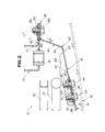
FIG. 2 is a horizontal cross-sectional view of the vehicle front body structure; -
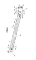
FIG. 3 is a perspective view showing a part of the vehicle front body structure including a high-rigidity plate member and a low-rigidity plate member connected together; -
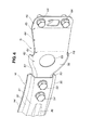
FIG. 4 is an enlarged perspective view of the low-rigidity plate member of the vehicle front body structure; and -
FIG. 5 is a horizontal cross-sectional view illustrative of the operation of the vehicle front body structure. - Referring now to the drawings and
FIGS. 1 and2 in particular, there is shown a vehiclefront body structure 10 according to a preferred embodiment of the present invention. The vehiclefront body structure 10 generally comprises right and left side frames 13 (only the left side frame being shown) extending in a longitudinal direction of the vehicle body, a high-rigidity plate member 15 disposed forwardly of front ends of the right andleft side frames 13 and extending in a transverse or width direction of the vehicle body, and a low-rigidity plate member 15 disposed between the high-rigidity plate member 14 and the front end of the right orleft side frame 13 and connecting the high-rigidity plate member 14 to the front end of the right orleft side frame 13. - Each of the right and
left side frames 13 has anend flange 17 extending from the front end of theside flange 13 in a lateral outward direction of the vehicle body for attachment to the low-rigidity plate member 15, and anut 18 for connection with a tow-hook 61 (FIG. 5 ). - In the illustrated embodiment, the high-
rigidity plate member 14 is a bumper beam, and the low-rigidity plate member 15 is a bumper beam extension disposed between thebumper beam 13 and theend flange 17 of the right orleft side frame 13. - The vehicle
front body structure 10 also includes a bumper face 19 (FIG. 2 ) disposed forwardly of the high-rigidity plate member (bumper beam) 14. Acondenser 21 for storing a refrigerant of a vehicle air conditioner system and aradiator 22 for cooling an engine are disposed in the named order behind the high-rigidity plate member 14. - As shown in
FIGS. 2-4 , the high-rigidity plate member 14 is a one-piece press-formed elongated beam having a hat-like shape in cross section. The high-rigidity plate member 14 includes afront wall 31 forming a beam body of the high-rigidity plate member 14, upper and lowerhorizontal walls front wall 31, and upper and lowervertical flanges horizontal walls - The front wall (beam body) 31 has left and
right reinforcement ribs front wall 31, and a pair of through-holes 38, 38 (FIG. 2 ) formed in each of left and right end portions of thefront wall 31 for attachment of the low-rigidity plate member 15. The through-holes - The low-rigidity plate member (bumper beam extension) 15 has a press-formed one-piece structure and includes a attachment portion 41 (
FIG. 2 ) adapted to be connected to the high-rigidity plate member 14, atransverse wall 42 extending continuously from theattachment portion 41 in a lateral outward direction (i.e., a widthwise outward direction) of the vehicle body, avertical wall 44 extending continuously rearwards from an outer end of thetransverse wall 42 in the longitudinal direction of the vehicle body toward the front end of the corresponding side frame 13 (left side frame in the illustrated embodiment) while forming abent portion 43 between thetransverse wall 42 and thelongitudinal wall 44, and anend flange 46 extending from arear end 63 of thelongitudinal wall 44 in a lateral outward direction of the vehicle body for attachment to theend flange 17 of theside frame 13. - The low-rigidity plate member (bumper beam extension) 15 is removably connected to the high-rigidity plate member (bumper beam) 14. The right low-
rigidity plate member 15 is configured in symmetric relation to the left low-rigidity plate member 15 about a longitudinal centerline of the vehicle, and a further description of the right low-rigidity plate member 15 can be omitted. - The
attachment portion 41 of the low-rigidity plate member 15 is formed as an integral end portion of thetransverse wall 42 and has a U-shape in cross section. The U-shapedattachment portion 41 includes afront wall section 51 and upper and lower horizontal wall sections 53 (only the lower wall section being shown inFIG. 2 ) extending rearwards from upper and lower edges of thefront wall section 51. Theattachment portion 41 has a pair of through-holes (not designated) and a pair ofnuts 55, 55 (FIG. 2 ) concentrically with the respective through-holes and welded to the rear surface of thefront wall section 51, so that by threading a pair ofbolts 54 from the through-holes 38 (FIG. 2 ) of the high-rigidity plate member 15 into thenuts 55, the low-rigidity plate member 15 can be attached to the high-rigidity plate member 14. - The
transverse wall 42 including theattachment portion 41 as one end portion thereof also has a U-shape in cross section. The U-shapedtransverse wall 42 includes afront wall section 56 and upper and lowerhorizontal wall sections front wall section 56. Thetransverse wall 42 has a through-hole 59 formed in thefront wall section 56 for the passage therethrough of the tow hook 61 (FIG. 5 ). - As shown in
FIGS. 3 and4 , thetransverse wall 42 is formed to flare in the lateral outward direction of the vehicle body and, hence, has a width gradually increased in the lateral outward direction of the vehicle body. The thus formed U-shapedtransverse wall 42 is highly resistant to deformation and rigid as compared to thelongitudinal wall 44. - The
longitudinal wall 44 has a flat planar shape and extends at an obtuse angle to thetransverse wall 42 so that afront end 62 of thelongitudinal wall 44 disposed inwardly of therear end 63 as viewed in the transverse or width direction of the vehicle body. The thus configuredlongitudinal wall 44 has a lower rigidity than thetransverse wall 42 and is susceptible to deformation or yielding as compared to thetransverse wall 42. - The
end flange 46 of the low-rigidity plate member 15 is attached to theend flange 17 of thecorresponding side frame 13 by a pair ofbolts end flange 46 has a pair of through-holes 65, 65 (FIG. 2 ) for the passage therethrough of thebolts end flange 17 of theside frame 13 has a triple-ply laminated structure and has a pair of through holes (not designated) and a pair ofnuts end flange 17, so that by threading thebolts 64 from the through-holes 65 (FIG. 2 ) of theend flange 46 into the nuts 66, the low-rigidity plate member 15 can be attached to theside frame 13. - As shown in
FIG. 2 , thelongitudinal wall 44 of the low-rigidity plate member (bumper beam extension) 15 is angled at an obtuse angle relative to thetransverse wall 42. This arrangement may be said that thelongitudinal wall 44 is inclined at an angle V to a line L1 passing in the longitudinal direction of the vehicle through a junction (or bent portion) 45 between thelongitudinal wall 44 and theend flange 46, the line L1 being parallel to the longitudinal centerline of the vehicle body. - By thus providing the inclination angle V to the
longitudinal wall 44, thelongitudinal wall 44 is likely to tilt down in the lateral inward direction of the vehicle body when subjected to a collision load acting from the front of the vehicle body. For instance, if the inclination angle V is zero (∀=0), the load bearing characteristic of thelongitudinal wall 44 depends completely on the thickness of thelongitudinal wall 44. Alternatively, if the inclination angle V is greater than (∀>0), the load bearing characteristic of thelongitudinal wall 44 can be determined by a combination of the thickness of thelongitudinal wall 44 and the inclination angle V of thelongitudinal wall 44. By thus providing the inclination angle, it is possible to increase the degree of freedom in determining the load bearing characteristic of thelongitudinal wall 44. - As shown in
FIG. 5 , when the high-rigidity plate member (bumper beam) 14 is subjected to a collision load acting from the front side thereof in an orthogonal direction as indicated by a profiled arrow a1, thevertical wall 44 starts deforming or yielding and tilts down in a lateral inward direction of the vehicle body as indicated by the arrow a2 while the bent portion acts as a starting point of tilting movement. With this deformation including tilting movement of thelongitudinal wall 44, the low-rigidity plate member 15 can absorb the collision load. - The tilting movement of the
longitudinal wall 44 is also able to offer another advantage that when the vehiclefront body structure 10 is subjected to an offset head-on collision, a collision load applied to one of the right and left sides of the high-rigidity plate member (bumper beam) 15 is transmitted to the other side through the tilting movement of the longitudinal wall 11. As a consequence, the impact absorbing capacity of the front body structure can be increased. - It will be appreciated from the foregoing description that in the vehicle front body structure embodying the invention, the low-rigidity plate member (bumper beam extension) 15 is connected at one end to one of left and right ends of the high-rigidity plate member (bumper beam) 14 and, at the other end, to the front end of a corresponding one of the right and
left side frame 13 via theend flange 46 attached to theend flange 17 of theside frame 13 projecting from the front end of theside frame 13 in a lateral outward direction of theside frame 13, and thelongitudinal wall 44 of the low-rigidity plate member 15 extends at an obtuse angle relative to thetransverse wall 42 so that a collision load can be absorbed as thelongitudinal wall 44 undergoes deformation and tilting movement. - With the vehicle front body structure thus constructed, at the time of a light collision, which may occur when the vehicle body collides with a soft object such as a pedestrian, the collision load can be efficiently absorbed as the
longitudinal wall 44 undergoes deformation and tilting movement. At the end of the collision, thelongitudinal wall 44 of the low-rigidity plate member 15 lies in front of the front end of thecorresponding side frame 13 and does not form an undeformed portion, which is produced in the case of the conventional bumper beam extension of a tubular shape. By virtue of thelongitudinal wall 44, it is possible to reduce the overall size of the low-rigidity plate member (bumper beam extension) in the longitudinal direction of the vehicle body. Furthermore, because of thelongitudinal wall 44 angled at an obtuse angle to the transverse wall 43 (or inclined at an angle to the longitudinal centerline of the vehicle body with thefront end 62 disposed inwardly of therear end 63 as viewed in the width direction of the vehicle body), the low-rigidity plate member 15 is able to transmit a collision load from one end to the other end of the high-rigidity plate member (bumper beam) 14 when the vehicle front body structure is subjected to an offset head-on collision. - Furthermore, to cope with a collision with a hard object such as a building, an oncoming vehicle and so on, the low-rigidity plate member (bumper beam extension) 15 is configured to have a sufficient cross sectional area, which is large enough to prevent the high-
rigidity plate member 14 from rupturing under the effect of the collision load, and the low-rigidity plate member 15 is connected to the front end of thecorresponding side frame 13 on a lateral outer side of theside frame 13 as viewed from the width direction of the vehicle body. With this arrangement, the high-rigidity plate member 14 moving backward during collision is reliably supported by the side frames while keeping a desired coupling rigidity between the high-rigidity plate member 14 and the side frames 13 via the low-rigidity plate members 15. - As thus far described, the vehicle body structure according to the present invention includes right and left side frames 13 extending in a longitudinal direction of the vehicle body, and a high-
rigidity plate member 14 disposed forwardly of front ends of the right and left side frames 13 and extending in a width direction of the vehicle body. The high-rigidity plate member 14 is connected to the front end of each of the right and left side frames via a low-rigidity plate member 15, which has a rigidity smaller than a rigidity of the high-rigidity plate member 14. The low-rigidity plate member 15 includes atransverse wall 42 connected to the high-rigidity plate member 14 and extending in the width direction of the vehicle body, and alongitudinal wall 44 extending from thetransverse wall 42 in the longitudinal direction of the vehicle body toward the front end of the right orleft side frame 13 in such a manner as to form abent portion 43 between thetransverse wall 42 and thevertical wall 44, thevertical wall 44 being connected to the front end of the right orleft side frame 13. When the high-rigidity plate member 14 is subjected to a collision load, the low-rigidity plate member 15 is deformable to start distorting at thebent portion 43 to thereby absorb the collision load. - When subjected to a relatively small collision load which may occur at a collision with a soft object such as a pedestrian, the low-
rigidity plate member 15 solely undergoes deformation or yielding to thereby absorb the collision load while the high-rigidity plate member remains undeformed. In this instance, the low-rigidity plate member 15 starts distorting at thebent portion 43 to cause thelongitudinal wall 44 to tilt in a lateral inward direction of the vehicle body and absorbs the collision load as thebent portion 43 moves in the same direction as the tilting movement of thelongitudinal wall 42. - Furthermore, since the low-
rigidity plate member 15 has a one-piece structure press-formed from a metal sheet, thelongitudinal wall 44 of the low-rigidity plate member 15 is yieldable in its entirety without leaving an unyielding portion when the low-rigidity plate member 15 is subjected to the collision load. Using suchlongitudinal wall 44 enables a reduction in size of the low-rigidity plate member 15 in the longitudinal direction of the vehicle body. The low-rigidity plate member (bumper beam extension) 15 and the high-rigidity plate member (bumper beam) 14 used in combination are able to perform a sufficiently large impact energy function when used in light vehicles that can provide only a relatively small installation space defined between the front ends of the right and left side frames 13 and abumper face 19 disposed forwardly of the high-rigidity plate member (bumper beam) 14. - In the vehicle
front body structure 10 of the present invention, thelongitudinal wall 44 of the low-rigidity plate member 15 is arranged to extend at an obtuse angle to the transverse wall 42 (or at an angle to a longitudinal centerline of the vehicle body) such that afront end 62 of thelongitudinal wall 44 is disposed inwardly of arear end 63 of thelongitudinal wall 44 as viewed in the width direction of the vehicle body. With this arrangement, a collision load applied to the high-rigidity plate member 15 at right angles to the latter will cause thevertical wall 44 to tilt in the lateral inward direction of the vehicle body. Thus, the collision load is transmitted via the high-rigidity plate member (bumper beam) 14 the right and left side frames. This arrangement is particularly advantageous when an offset head-on collision occurs because the collision load acting on one side of the high-rigidity plate member 14 can be efficiently distributed via the high-rigidity plate member 14 to the right and left side frames 13. As a result, the impact absorbing efficiency of the vehiclefront body structure 10 increases sufficiently. - Each of the right and left side frames 13 has an
end flange 17 extending from the front end thereof in the lateral outward direction of the vehicle body, and the low-rigidity plate member 15 has anend flange 46 extending from therear end 63 of thevertical wall 44 in the lateral outward direction of the vehicle body. Theend flange 46 of the low-rigidity plate member 15 is attached to theend flange 17 of the right orleft side frame 13. With this arrangement, since the low-rigidity plate member 15 is connected to the right orleft side frame 13 on a lateral outer side thereof, when the high-rigidity plate member 14 is subjected to a large collision load which may occur at a collision with a hard object such as an oncoming vehicle, the high-rigidity plate 14 while being displaced backwards during collision is supported by the side frames 13. The large collision load can thus be born by the side frames. Furthermore, by connecting the low-rigidity plate member 15 and the right orleft side frame 13 on the lateral outer side of theside frame 13, it is possible to maintain a necessary area of thetransverse wall 42 even when thevertical wall 44 is arranged at the obtuse angle to thetransverse wall 42. This arrangement allows thetransverse wall 42 to have a through-hole 59 for the passage therethrough of a tow hook 61 (FIG. 5 ). - Furthermore, since the
transverse wall 42 of the low-rigidity plate member 15 has a U-shape or a hat-like shape in cross section, the rigidity of thetransverse wall 42 is sufficiently large enough to ensure that the low-rigidity plate member 15 is able to start distorting at thebent portion 43 to cause tilting of the longitudinal wall in the lateral inward direction of the vehicle body when a collision load acts on the high-rigidity plate member 14. This arrangement adds to the impact energy absorbing efficiency of the vehiclefront body structure 10. - The low-
rigidity plate member 15, which is removably connected to the high-rigidity plate member 15, is advantageous because during collision with a relatively small collision load, only the low-rigidity plate member 15 of the vehiclefront body structure 10 undergoes plastic deformation or collapsing to thereby absorb the collision load. In such instance, by replacing the collapsed low-rigidity plate member 15 with a new low-rigidity plate member, it is possible to repair the vehiclefront body structure 10 easily at a relatively low cost. A further advantage attainable by the replaceable arrangement of the low-rigidity plate member 15 is that the vehiclefront body structure 10 can be used for another type of vehicle by merely adjusting the strength and rigidity of the low-rigidity plate member 15. The compatibility of the vehiclefront body structure 10 can thus be increased. - Although in the illustrated embodiment, the
transverse wall 42 of the low-rigidity plate member (bumper beam extension) 15 has a U-shape in cross section, a hat-like shape in cross section may be used for thetransverse wall 42. Furthermore, the high-rigidity plate member (bumper beam) 14 and the low-rigidity plate member (bumper beam extension) 15 are preferably configured to have a section modulus, which is sufficient large enough to withstand a tensile load that may be produced during ordinal off-set head-on collision. With this arrangement, when an offset head-on collision occurs, a collision load acting on one side of the high-rigidity plate member 14 is distributed via the high-rigidity plate member 14 to both of the right and left side frames 13. As a result, the vehiclefront body structure 10 can achieve an improved impact absorbing operation without causing deformation of eitherside frame 13.
Claims (5)
- A vehicle front body structure including right and left side frames (13) extending in a longitudinal direction of the vehicle body, and a high-rigidity plate member (14) disposed forwardly of front ends of the right and left side frames (13) and extending in a width direction of the vehicle body, characterized in that the high-rigidity plate member (14) is connected via a low-rigidity plate member (15) to the front end of each of the right and left side frames (13), the low-rigidity plate member (15) having a rigidity smaller than a rigidity of the high-rigidity plate member (14), wherein the low-rigidity plate member (15) includes a transverse wall (42) connected to the high-rigidity plate member (14) and extending in the width direction of the vehicle body, and a longitudinal wall (44) extending from the transverse wall (42) in the longitudinal direction of the vehicle body toward the front end of the right or left side frame (13) in such a manner as form a bent portion (43) between the transverse wall (42) and the vertical wall (44) and connected to the front end of the right or left side frame (13), and wherein when the high-rigidity plate member (14) is subjected to a collision load, the low-rigidity plate member (15) is deformable to start distorting at the bent portion (43) to thereby absorb the collision load.
- The vehicle front body structure according to claim 1, wherein the longitudinal wall (44) extends at an obtuse angle to the transverse wall (42) such that a front end (62) of the longitudinal wall (44) is disposed inwardly of a rear end (63) of the longitudinal wall (44) as viewed in the width direction of the vehicle body.
- The vehicle front body structure according to claim 1 or 2, wherein each of the right and left side frames (13) has an end flange (17) extending from the front end thereof in a lateral outward direction of the vehicle body, and the low-rigidity plate member (15) further has an end flange (46) extending from an end of the vertical wall (44) in a lateral outward direction of the vehicle body, the end flange (46) of the low-rigidity plate member (15) being attached to the end flange (17) of the right or left side frame (13).
- The vehicle front body structure according to one of claims 1 to 3, wherein the transverse wall (42) of the low-rigidity plate member (15) has a U-shape or a hat-like shape in cross section.
- The vehicle front body structure according to one of claims 1 to 4, wherein the low-rigidity plate member (15) is removably connected to the high-rigidity plate member (14).
Applications Claiming Priority (1)
| Application Number | Priority Date | Filing Date | Title |
|---|---|---|---|
| JP2009139601A JP4856740B2 (en) | 2009-06-10 | 2009-06-10 | Body front structure |
Publications (2)
| Publication Number | Publication Date |
|---|---|
| EP2263919A1 true EP2263919A1 (en) | 2010-12-22 |
| EP2263919B1 EP2263919B1 (en) | 2012-05-09 |
Family
ID=42308334
Family Applications (1)
| Application Number | Title | Priority Date | Filing Date |
|---|---|---|---|
| EP10165473A Not-in-force EP2263919B1 (en) | 2009-06-10 | 2010-06-10 | Automobile front body structure |
Country Status (4)
| Country | Link |
|---|---|
| EP (1) | EP2263919B1 (en) |
| JP (1) | JP4856740B2 (en) |
| CN (1) | CN101920685B (en) |
| AT (1) | ATE556893T1 (en) |
Cited By (2)
| Publication number | Priority date | Publication date | Assignee | Title |
|---|---|---|---|---|
| GB2495834A (en) * | 2011-10-20 | 2013-04-24 | Gm Global Tech Operations Inc | Shock absorbing mounting for vehicle bumper |
| FR3133353A1 (en) * | 2022-03-11 | 2023-09-15 | Psa Automobiles Sa | Rear bumper assembly for motor vehicle |
Families Citing this family (4)
| Publication number | Priority date | Publication date | Assignee | Title |
|---|---|---|---|---|
| JP2012153280A (en) * | 2011-01-27 | 2012-08-16 | Nissan Motor Co Ltd | Bumper for vehicle |
| JP5861869B2 (en) * | 2011-11-08 | 2016-02-16 | スズキ株式会社 | Fixing structure of towing hook for vehicle |
| KR101365950B1 (en) | 2012-03-29 | 2014-02-28 | 울산대학교 산학협력단 | Collision safety apparatus of vehicle and control method thereof |
| DE102020112168B3 (en) | 2020-05-06 | 2021-09-30 | Dr. Ing. H.C. F. Porsche Aktiengesellschaft | Apron arrangement for a bumper |
Citations (3)
| Publication number | Priority date | Publication date | Assignee | Title |
|---|---|---|---|---|
| EP0888953A2 (en) * | 1997-06-30 | 1999-01-07 | Mazda Motor Corporation | Front body structure for vehicle |
| EP1149756A2 (en) * | 2000-04-25 | 2001-10-31 | Nissan Motor Company, Limited | Body structure of vehicle |
| JP2007190964A (en) | 2006-01-17 | 2007-08-02 | Honda Motor Co Ltd | Front body structure of automobile |
Family Cites Families (6)
| Publication number | Priority date | Publication date | Assignee | Title |
|---|---|---|---|---|
| DE2043524A1 (en) * | 1970-09-02 | 1972-03-09 | Daimler-Benz Ag, 7000 Stuttgart | Front assembly with radiator for motor vehicles |
| JPH0450197Y2 (en) * | 1986-07-28 | 1992-11-26 | ||
| JP2003306095A (en) * | 2002-04-12 | 2003-10-28 | Nissan Motor Co Ltd | Vehicle bumper mounting structure |
| JP4026522B2 (en) * | 2003-03-19 | 2007-12-26 | 日産自動車株式会社 | Body front structure |
| JP2006232147A (en) * | 2005-02-25 | 2006-09-07 | Toyota Motor Corp | Body front structure |
| JP2008120256A (en) * | 2006-11-13 | 2008-05-29 | Toyota Motor Corp | Shock absorption structure for vehicles |
-
2009
- 2009-06-10 JP JP2009139601A patent/JP4856740B2/en not_active Expired - Fee Related
-
2010
- 2010-06-09 CN CN201010195789.2A patent/CN101920685B/en not_active Expired - Fee Related
- 2010-06-10 EP EP10165473A patent/EP2263919B1/en not_active Not-in-force
- 2010-06-10 AT AT10165473T patent/ATE556893T1/en active
Patent Citations (3)
| Publication number | Priority date | Publication date | Assignee | Title |
|---|---|---|---|---|
| EP0888953A2 (en) * | 1997-06-30 | 1999-01-07 | Mazda Motor Corporation | Front body structure for vehicle |
| EP1149756A2 (en) * | 2000-04-25 | 2001-10-31 | Nissan Motor Company, Limited | Body structure of vehicle |
| JP2007190964A (en) | 2006-01-17 | 2007-08-02 | Honda Motor Co Ltd | Front body structure of automobile |
Cited By (3)
| Publication number | Priority date | Publication date | Assignee | Title |
|---|---|---|---|---|
| GB2495834A (en) * | 2011-10-20 | 2013-04-24 | Gm Global Tech Operations Inc | Shock absorbing mounting for vehicle bumper |
| US9227584B2 (en) | 2011-10-20 | 2016-01-05 | GM Global Technology Operations LLC | Support device |
| FR3133353A1 (en) * | 2022-03-11 | 2023-09-15 | Psa Automobiles Sa | Rear bumper assembly for motor vehicle |
Also Published As
| Publication number | Publication date |
|---|---|
| JP2010285041A (en) | 2010-12-24 |
| CN101920685A (en) | 2010-12-22 |
| EP2263919B1 (en) | 2012-05-09 |
| JP4856740B2 (en) | 2012-01-18 |
| ATE556893T1 (en) | 2012-05-15 |
| CN101920685B (en) | 2013-01-16 |
Similar Documents
| Publication | Publication Date | Title |
|---|---|---|
| US8246105B2 (en) | Frontal structure for a motor vehicle | |
| JP5357953B2 (en) | Body front structure | |
| US20150251613A1 (en) | Front structure of vehicle body | |
| EP2263919B1 (en) | Automobile front body structure | |
| JP2007038839A (en) | Rear body structure of automobile | |
| KR20150134977A (en) | Vehicle body reinforcing structure for coping with small overlap collision | |
| CN108349546A (en) | The side body structure of vehicle | |
| JP3927845B2 (en) | Bumper support structure for vehicles | |
| JP6284056B1 (en) | Vehicle frame structure | |
| JP4830017B2 (en) | Bumper structure for passenger cars | |
| JP4035292B2 (en) | Bumper reinforcement with excellent offset impact | |
| JP4303659B2 (en) | Shock absorption structure of automobile | |
| US5346275A (en) | Rear end of a vehicle body | |
| JP4539320B2 (en) | Mounting structure of tow hook for vehicle | |
| JP4894270B2 (en) | Front body structure of automobile | |
| JP5337117B2 (en) | Rear body structure | |
| CN114132386A (en) | rear body structure | |
| JP4894613B2 (en) | Bumper mounting structure for vehicles | |
| JP4367190B2 (en) | Front body structure of automobile | |
| EP4316919A1 (en) | Side extension for crash management system | |
| CN215663661U (en) | Automobile engine cabin frame structure and automobile | |
| US9302712B2 (en) | Vehicle body front structure | |
| CN109923003B (en) | Impact absorbing structure for vehicle | |
| JP2006001449A (en) | Bumper structure for passenger car | |
| EP2428432A1 (en) | Front side vehicle body structure |
Legal Events
| Date | Code | Title | Description |
|---|---|---|---|
| PUAI | Public reference made under article 153(3) epc to a published international application that has entered the european phase |
Free format text: ORIGINAL CODE: 0009012 |
|
| 17P | Request for examination filed |
Effective date: 20100610 |
|
| AK | Designated contracting states |
Kind code of ref document: A1 Designated state(s): AL AT BE BG CH CY CZ DE DK EE ES FI FR GB GR HR HU IE IS IT LI LT LU LV MC MK MT NL NO PL PT RO SE SI SK SM TR |
|
| AX | Request for extension of the european patent |
Extension state: BA ME RS |
|
| RIC1 | Information provided on ipc code assigned before grant |
Ipc: B62D 21/15 20060101ALI20110216BHEP Ipc: B60R 19/26 20060101AFI20110216BHEP Ipc: B60R 19/34 20060101ALI20110216BHEP |
|
| 17Q | First examination report despatched |
Effective date: 20110511 |
|
| GRAP | Despatch of communication of intention to grant a patent |
Free format text: ORIGINAL CODE: EPIDOSNIGR1 |
|
| GRAS | Grant fee paid |
Free format text: ORIGINAL CODE: EPIDOSNIGR3 |
|
| GRAA | (expected) grant |
Free format text: ORIGINAL CODE: 0009210 |
|
| AK | Designated contracting states |
Kind code of ref document: B1 Designated state(s): AL AT BE BG CH CY CZ DE DK EE ES FI FR GB GR HR HU IE IS IT LI LT LU LV MC MK MT NL NO PL PT RO SE SI SK SM TR |
|
| REG | Reference to a national code |
Ref country code: GB Ref legal event code: FG4D |
|
| REG | Reference to a national code |
Ref country code: AT Ref legal event code: REF Ref document number: 556893 Country of ref document: AT Kind code of ref document: T Effective date: 20120515 Ref country code: CH Ref legal event code: EP |
|
| REG | Reference to a national code |
Ref country code: IE Ref legal event code: FG4D |
|
| REG | Reference to a national code |
Ref country code: DE Ref legal event code: R096 Ref document number: 602010001384 Country of ref document: DE Effective date: 20120705 |
|
| REG | Reference to a national code |
Ref country code: NL Ref legal event code: VDEP Effective date: 20120509 |
|
| REG | Reference to a national code |
Ref country code: LT Ref legal event code: MG4D Effective date: 20120509 |
|
| PG25 | Lapsed in a contracting state [announced via postgrant information from national office to epo] |
Ref country code: FI Free format text: LAPSE BECAUSE OF FAILURE TO SUBMIT A TRANSLATION OF THE DESCRIPTION OR TO PAY THE FEE WITHIN THE PRESCRIBED TIME-LIMIT Effective date: 20120509 Ref country code: SE Free format text: LAPSE BECAUSE OF FAILURE TO SUBMIT A TRANSLATION OF THE DESCRIPTION OR TO PAY THE FEE WITHIN THE PRESCRIBED TIME-LIMIT Effective date: 20120509 Ref country code: PL Free format text: LAPSE BECAUSE OF FAILURE TO SUBMIT A TRANSLATION OF THE DESCRIPTION OR TO PAY THE FEE WITHIN THE PRESCRIBED TIME-LIMIT Effective date: 20120509 Ref country code: CY Free format text: LAPSE BECAUSE OF FAILURE TO SUBMIT A TRANSLATION OF THE DESCRIPTION OR TO PAY THE FEE WITHIN THE PRESCRIBED TIME-LIMIT Effective date: 20120509 Ref country code: NO Free format text: LAPSE BECAUSE OF FAILURE TO SUBMIT A TRANSLATION OF THE DESCRIPTION OR TO PAY THE FEE WITHIN THE PRESCRIBED TIME-LIMIT Effective date: 20120809 Ref country code: LT Free format text: LAPSE BECAUSE OF FAILURE TO SUBMIT A TRANSLATION OF THE DESCRIPTION OR TO PAY THE FEE WITHIN THE PRESCRIBED TIME-LIMIT Effective date: 20120509 Ref country code: IS Free format text: LAPSE BECAUSE OF FAILURE TO SUBMIT A TRANSLATION OF THE DESCRIPTION OR TO PAY THE FEE WITHIN THE PRESCRIBED TIME-LIMIT Effective date: 20120909 |
|
| REG | Reference to a national code |
Ref country code: AT Ref legal event code: MK05 Ref document number: 556893 Country of ref document: AT Kind code of ref document: T Effective date: 20120509 |
|
| PG25 | Lapsed in a contracting state [announced via postgrant information from national office to epo] |
Ref country code: LV Free format text: LAPSE BECAUSE OF FAILURE TO SUBMIT A TRANSLATION OF THE DESCRIPTION OR TO PAY THE FEE WITHIN THE PRESCRIBED TIME-LIMIT Effective date: 20120509 Ref country code: SI Free format text: LAPSE BECAUSE OF FAILURE TO SUBMIT A TRANSLATION OF THE DESCRIPTION OR TO PAY THE FEE WITHIN THE PRESCRIBED TIME-LIMIT Effective date: 20120509 Ref country code: HR Free format text: LAPSE BECAUSE OF FAILURE TO SUBMIT A TRANSLATION OF THE DESCRIPTION OR TO PAY THE FEE WITHIN THE PRESCRIBED TIME-LIMIT Effective date: 20120509 Ref country code: GR Free format text: LAPSE BECAUSE OF FAILURE TO SUBMIT A TRANSLATION OF THE DESCRIPTION OR TO PAY THE FEE WITHIN THE PRESCRIBED TIME-LIMIT Effective date: 20120810 Ref country code: PT Free format text: LAPSE BECAUSE OF FAILURE TO SUBMIT A TRANSLATION OF THE DESCRIPTION OR TO PAY THE FEE WITHIN THE PRESCRIBED TIME-LIMIT Effective date: 20120910 |
|
| PG25 | Lapsed in a contracting state [announced via postgrant information from national office to epo] |
Ref country code: BE Free format text: LAPSE BECAUSE OF FAILURE TO SUBMIT A TRANSLATION OF THE DESCRIPTION OR TO PAY THE FEE WITHIN THE PRESCRIBED TIME-LIMIT Effective date: 20120509 |
|
| PG25 | Lapsed in a contracting state [announced via postgrant information from national office to epo] |
Ref country code: RO Free format text: LAPSE BECAUSE OF FAILURE TO SUBMIT A TRANSLATION OF THE DESCRIPTION OR TO PAY THE FEE WITHIN THE PRESCRIBED TIME-LIMIT Effective date: 20120509 Ref country code: CZ Free format text: LAPSE BECAUSE OF FAILURE TO SUBMIT A TRANSLATION OF THE DESCRIPTION OR TO PAY THE FEE WITHIN THE PRESCRIBED TIME-LIMIT Effective date: 20120509 Ref country code: SK Free format text: LAPSE BECAUSE OF FAILURE TO SUBMIT A TRANSLATION OF THE DESCRIPTION OR TO PAY THE FEE WITHIN THE PRESCRIBED TIME-LIMIT Effective date: 20120509 Ref country code: AT Free format text: LAPSE BECAUSE OF FAILURE TO SUBMIT A TRANSLATION OF THE DESCRIPTION OR TO PAY THE FEE WITHIN THE PRESCRIBED TIME-LIMIT Effective date: 20120509 Ref country code: MC Free format text: LAPSE BECAUSE OF NON-PAYMENT OF DUE FEES Effective date: 20120630 Ref country code: NL Free format text: LAPSE BECAUSE OF FAILURE TO SUBMIT A TRANSLATION OF THE DESCRIPTION OR TO PAY THE FEE WITHIN THE PRESCRIBED TIME-LIMIT Effective date: 20120509 Ref country code: DK Free format text: LAPSE BECAUSE OF FAILURE TO SUBMIT A TRANSLATION OF THE DESCRIPTION OR TO PAY THE FEE WITHIN THE PRESCRIBED TIME-LIMIT Effective date: 20120509 Ref country code: EE Free format text: LAPSE BECAUSE OF FAILURE TO SUBMIT A TRANSLATION OF THE DESCRIPTION OR TO PAY THE FEE WITHIN THE PRESCRIBED TIME-LIMIT Effective date: 20120509 |
|
| PG25 | Lapsed in a contracting state [announced via postgrant information from national office to epo] |
Ref country code: MK Free format text: LAPSE BECAUSE OF FAILURE TO SUBMIT A TRANSLATION OF THE DESCRIPTION OR TO PAY THE FEE WITHIN THE PRESCRIBED TIME-LIMIT Effective date: 20120509 Ref country code: IT Free format text: LAPSE BECAUSE OF FAILURE TO SUBMIT A TRANSLATION OF THE DESCRIPTION OR TO PAY THE FEE WITHIN THE PRESCRIBED TIME-LIMIT Effective date: 20120509 |
|
| PLBE | No opposition filed within time limit |
Free format text: ORIGINAL CODE: 0009261 |
|
| STAA | Information on the status of an ep patent application or granted ep patent |
Free format text: STATUS: NO OPPOSITION FILED WITHIN TIME LIMIT |
|
| REG | Reference to a national code |
Ref country code: IE Ref legal event code: MM4A |
|
| REG | Reference to a national code |
Ref country code: FR Ref legal event code: ST Effective date: 20130228 |
|
| 26N | No opposition filed |
Effective date: 20130212 |
|
| PG25 | Lapsed in a contracting state [announced via postgrant information from national office to epo] |
Ref country code: ES Free format text: LAPSE BECAUSE OF FAILURE TO SUBMIT A TRANSLATION OF THE DESCRIPTION OR TO PAY THE FEE WITHIN THE PRESCRIBED TIME-LIMIT Effective date: 20120820 Ref country code: IE Free format text: LAPSE BECAUSE OF NON-PAYMENT OF DUE FEES Effective date: 20120610 Ref country code: FR Free format text: LAPSE BECAUSE OF NON-PAYMENT OF DUE FEES Effective date: 20120709 |
|
| REG | Reference to a national code |
Ref country code: DE Ref legal event code: R097 Ref document number: 602010001384 Country of ref document: DE Effective date: 20130212 |
|
| PG25 | Lapsed in a contracting state [announced via postgrant information from national office to epo] |
Ref country code: MT Free format text: LAPSE BECAUSE OF FAILURE TO SUBMIT A TRANSLATION OF THE DESCRIPTION OR TO PAY THE FEE WITHIN THE PRESCRIBED TIME-LIMIT Effective date: 20120509 Ref country code: BG Free format text: LAPSE BECAUSE OF FAILURE TO SUBMIT A TRANSLATION OF THE DESCRIPTION OR TO PAY THE FEE WITHIN THE PRESCRIBED TIME-LIMIT Effective date: 20120809 |
|
| PG25 | Lapsed in a contracting state [announced via postgrant information from national office to epo] |
Ref country code: AL Free format text: LAPSE BECAUSE OF FAILURE TO SUBMIT A TRANSLATION OF THE DESCRIPTION OR TO PAY THE FEE WITHIN THE PRESCRIBED TIME-LIMIT Effective date: 20120509 |
|
| PG25 | Lapsed in a contracting state [announced via postgrant information from national office to epo] |
Ref country code: TR Free format text: LAPSE BECAUSE OF FAILURE TO SUBMIT A TRANSLATION OF THE DESCRIPTION OR TO PAY THE FEE WITHIN THE PRESCRIBED TIME-LIMIT Effective date: 20120509 |
|
| PG25 | Lapsed in a contracting state [announced via postgrant information from national office to epo] |
Ref country code: LU Free format text: LAPSE BECAUSE OF NON-PAYMENT OF DUE FEES Effective date: 20120610 Ref country code: SM Free format text: LAPSE BECAUSE OF FAILURE TO SUBMIT A TRANSLATION OF THE DESCRIPTION OR TO PAY THE FEE WITHIN THE PRESCRIBED TIME-LIMIT Effective date: 20120509 |
|
| PG25 | Lapsed in a contracting state [announced via postgrant information from national office to epo] |
Ref country code: HU Free format text: LAPSE BECAUSE OF FAILURE TO SUBMIT A TRANSLATION OF THE DESCRIPTION OR TO PAY THE FEE WITHIN THE PRESCRIBED TIME-LIMIT Effective date: 20100610 |
|
| PGFP | Annual fee paid to national office [announced via postgrant information from national office to epo] |
Ref country code: GB Payment date: 20140604 Year of fee payment: 5 |
|
| PGFP | Annual fee paid to national office [announced via postgrant information from national office to epo] |
Ref country code: DE Payment date: 20140603 Year of fee payment: 5 |
|
| REG | Reference to a national code |
Ref country code: CH Ref legal event code: PL |
|
| PG25 | Lapsed in a contracting state [announced via postgrant information from national office to epo] |
Ref country code: CH Free format text: LAPSE BECAUSE OF NON-PAYMENT OF DUE FEES Effective date: 20140630 Ref country code: LI Free format text: LAPSE BECAUSE OF NON-PAYMENT OF DUE FEES Effective date: 20140630 |
|
| REG | Reference to a national code |
Ref country code: DE Ref legal event code: R119 Ref document number: 602010001384 Country of ref document: DE |
|
| GBPC | Gb: european patent ceased through non-payment of renewal fee |
Effective date: 20150610 |
|
| PG25 | Lapsed in a contracting state [announced via postgrant information from national office to epo] |
Ref country code: GB Free format text: LAPSE BECAUSE OF NON-PAYMENT OF DUE FEES Effective date: 20150610 Ref country code: DE Free format text: LAPSE BECAUSE OF NON-PAYMENT OF DUE FEES Effective date: 20160101 |