EP2263841A1 - Method and apparatus for measuring the rotation of a log and for correcting the rotation error - Google Patents
Method and apparatus for measuring the rotation of a log and for correcting the rotation error Download PDFInfo
- Publication number
- EP2263841A1 EP2263841A1 EP10397509A EP10397509A EP2263841A1 EP 2263841 A1 EP2263841 A1 EP 2263841A1 EP 10397509 A EP10397509 A EP 10397509A EP 10397509 A EP10397509 A EP 10397509A EP 2263841 A1 EP2263841 A1 EP 2263841A1
- Authority
- EP
- European Patent Office
- Prior art keywords
- log
- marking
- rotation
- rotation angle
- computing unit
- Prior art date
- Legal status (The legal status is an assumption and is not a legal conclusion. Google has not performed a legal analysis and makes no representation as to the accuracy of the status listed.)
- Withdrawn
Links
Images

Classifications
-
- B—PERFORMING OPERATIONS; TRANSPORTING
- B27—WORKING OR PRESERVING WOOD OR SIMILAR MATERIAL; NAILING OR STAPLING MACHINES IN GENERAL
- B27B—SAWS FOR WOOD OR SIMILAR MATERIAL; COMPONENTS OR ACCESSORIES THEREFOR
- B27B31/00—Arrangements for conveying, loading, turning, adjusting, or discharging the log or timber, specially designed for saw mills or sawing machines
- B27B31/06—Adjusting equipment, e.g. using optical projection
-
- B—PERFORMING OPERATIONS; TRANSPORTING
- B27—WORKING OR PRESERVING WOOD OR SIMILAR MATERIAL; NAILING OR STAPLING MACHINES IN GENERAL
- B27B—SAWS FOR WOOD OR SIMILAR MATERIAL; COMPONENTS OR ACCESSORIES THEREFOR
- B27B31/00—Arrangements for conveying, loading, turning, adjusting, or discharging the log or timber, specially designed for saw mills or sawing machines
- B27B31/04—Turning equipment
Definitions
- the object of the invention is a method as presented in the preamble of claim 1 and an apparatus as presented in the preamble of claim 6 for measuring the rotation of a log and for correcting the rotation error.
- a drawback in both of these methods is that they are based on a visual estimation, and the log is not necessarily brought into the optimal position in this way.
- the methods are also quite slow.
- a log scanner measures the shape of the log and then controls the rotating apparatuses through an automatic system.
- rotation will occur and be implemented according to a reference value.
- the rotating apparatus is not necessarily always able to rotate a log into the optimal position. If, for example, the slipperiness or defectiveness, such as knot protuberances or corresponding, of the wood or swaying of the log on the line prevents implementation of the optimal rotation, or if the rotating apparatus otherwise operates badly, a rotation error occurs.
- a solution is known in the art, wherein a meter that is downstream of the squaring phase performed by the chipping canter, measures the squared timber. The shape of the squared timber is compared to the shape calculated by a log scanner that is upstream of the chipping canter. With this solution any possible systematic error in rotating the log can be detected on the basis of the measurements and the correction angle with which the error could be corrected can be reported to the first log scanner. The log scanner then takes the correction angle into account when determining the rotation angle of the next log.
- a weakness of this solution is that only systematic rotation errors and the rotation average can be corrected with it, but not a rotation divergence. The magnitude of a divergence has a particularly important effect on the yield to be received from logs.
- a solution is also known in the art wherein two log scanners are used, of which the first measures the logs and calculates the desired rotation angle for the logs, and the second measures whether the logs are in the targeted position after the rotation.
- This solution an error of the first rotation occurring in the rotation of an individual log can be corrected.
- a weakness of this solution is the mechanics and space requirement of the duplicated apparatus, which limits installation of the application in existing lines. Neither can a possible error of the second rotation be corrected with this method.
- Canadian patent application no. CA2480976 presents a solution wherein a marking is made on an end of the log before rotation and the angular position of the marking is monitored with cameras during the rotation. By monitoring the marking, a possible error that occurred in the rotation can be detected and the rotation error can be corrected.
- a problem is that it can be difficult to make a marking on the end of a log that can be monitored with cameras, because ends of logs are not always similar in, among other things, their shape and color. The end of a log can e.g. have become darkened if it has been in a damp location for a long time.
- a problem in this solution is also that, owing to the marking being on the end of the log, the marking can be awkward to monitor as the logs move at a high speed on the conveyor. Owing to this problem, it may be necessary to slow down the speed of the conveyor or additional monitoring cameras may have to be fitted on the line, which in turn increases costs. It is safest in this case that the logs are rotated when they are stationary and longitudinal movement is only allowed for a log that has rotated into the correct position. This type of a solution, however, reduces efficiency and capacity.
- the aim of this invention is to eliminate the aforementioned drawbacks and to achieve a method and an apparatus that are as inexpensive and simple as possible for measuring the rotation of a log and for correcting the rotation error, which apparatus can be installed in existing sawmill lines without major modifications to the line.
- the aim is that each individual log could be turned into a sawing position that is as optimal as possible.
- the method according to the invention is characterized by what is disclosed in the characterization part of claim 1.
- the apparatus according to the invention is characterized by what is disclosed in the characterization part of claim 6.
- Other embodiments of the invention are characterized by what is disclosed in the other claims.
- One advantage of the solution according to the invention is that any possible error or inaccuracy occurring in the rotation of a log can be detected and also corrected automatically. Another advantage is that by means of the solution a correction can be made to each individual log such that each log is brought into the desired sawing position. A further advantage is that as large a part of the timber as possible can be used and as little wood as possible is wasted. Another advantage is that detection and correction of a defective rotation is quick. It is also an advantage that the marking made on the log is easily monitored with a monitoring device, owing to which all the logs are reliably rotated into the desired sawing position. A further advantage is that the solution according to the invention is economic in its space requirements and simple and inexpensive to implement.
- One advantage is also that a marking made with a colored or fluorescent ink is clearly distinguishable so that measurement of the position is quick and easy to perform.
- Another advantage is good efficiency, because the position of a log can be measured reliably during the longitudinal movement of the log and the log does not need to be stopped during the measuring.
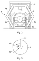
- Fig. 1 presents a top view and Fig. 2 a view from the rear end of a simplified apparatus, in which the log is arranged to be conveyed and to be rotated. More precisely, in Fig. 2 the apparatus is presented as viewed from between the parts 8 and 9 in Fig. 1 , in the direction of the part 8.
- the apparatus comprises a line 1, on which the logs 2 are arranged to travel forwards. The log 2 comes debarked to the line 1 from the debarking machine and the log 2 is arranged to move at the start of the line on a log conveyor 1a.
- a log scanner connected to a computing unit 3a is disposed at the beginning of the line, which measuring apparatus is arranged to measure the shape of a log 2 coming to the line and to determine on the basis of this, by means of the computing unit 3a, the optimal position for each log 2 from the viewpoint of the yield, into which position the log should be rotated essentially around its longitudinal axis before sawing.
- the operation of the log scanner 3 is based on e.g. laser technology and/or camera technology.
- the computing unit 3a can also be arranged to control the later phases of the treatment of the log.
- a marking device 5 fixed to a carrier 4 is fitted next on the line 1 in the direction of travel of the log 2, which marking device is disposed above the line 1.
- the marking device 5 is arranged to make a marking 10, such as e.g. a line or dashed line as in this embodiment of the invention, on the log 2 traveling below it.
- the marking type used by the marking device 5 can be e.g. a paint, ink, fluorescent ink, or corresponding, of some color.
- the marking device 5 is thus arranged to make a marking 10 on the log 2 traveling below it such that it sprays a marking agent downwards at certain intervals and when the log 2 moves below the marking device 5 an essentially straight dashed line is drawn on the side of the log.
- the marking 10 is not necessarily made on the whole length of the log 2, but instead a dashed line covering a part of the log 2 is generally sufficient also.
- the marking 10 covers at least approx. 5% of the whole length of the log, more suitably approx. 10-80% of the length of the log and most preferably approx. 20-40% of the length of the log. The longer the marking 10 is, the better it is visible and the better it can be read before the end of the log 2 is in the blades of the saw. However, a marking 10 that is as short as possible saves the coloring agent used.
- the marking device 5 is additionally protected such that it will not be damaged if a log 2 traveling on the line collides with it. If, for example, a log with an expanded butt end collides with the marking device 5, the device yields and thus swerves out of the way of the log.
- a monitoring device 6 connected to a monitoring-computing unit 7 is fitted in connection with the line 1, which monitoring device is arranged to measure the rotation of the log 2 essentially around its longitudinal axis.
- the monitoring-computing unit 7 of the monitoring device 6 is also connected to the computing unit 3a of the log scanner 3.
- a rotating apparatus 8 is fitted in connection with the line 1, which rotating apparatus is arranged to rotate the log 2 into the desired sawing position determined earlier by the computing unit 3a.
- the rotating apparatus 8 comprises two rolls 8a, which are arranged to grip the log 2 on both sides of the log.
- the rolls 8a are fixed to a rim 8b, which is arranged to be rotating and is fitted around the line 1.
- the rotating apparatus 8 is arranged to rotate the log 2 such that the rolls 8a are arranged to grip the log 2 and the rim 8b is arranged to rotate to the extent that it is desired to rotate the log 2 around its longitudinal axis.
- the rolls 8a are also arranged to rotate and thus to convey the log 2 forwards in the apparatus, because the log conveyor 1a ends before the monitoring device 6.
- the monitoring device 6 comprises a hexagonally-shaped frame 6a, which is fitted around the line 1 and through which the log 2 is arranged to travel.
- a measuring means 6b is fitted to each of the six sides of the inner rim of the frame 6a, which means are e.g. color line cameras.
- the monitoring device 6 is arranged to measure the implemented rotation angle of the log 2 made by the rotating apparatus 8 such that the monitoring device 6 reads, by means of the measuring means 6b, the position of the dashed line that functions as a marking 10 drawn on the log 2 before rotation, monitors the angular position of the dashed line when the log 2 is rotating, and reads the position of the dashed line after rotation. After this the rotation angle actually implemented is calculated based on the change in the position of the marking 10.
- the apparatus comprises a corrective rotator 9, which is disposed a suitable distance after the rotating apparatus 8 in the direction of travel of the log 2.
- Fig. 3 presents a log 2 as viewed from the end, on which two rotation angles A and B are marked.
- the angle A is an example of the rotation angle needed and the angle B of the rotation angle implemented.
- the position of the original marking 10 has moved by the extent of the angle B to the point 10', whereas according to the rotation needed the position should be at the point 10".
- the log 2 has thus been rotated around its longitudinal axis less than desired.
- the correction angle needed is A - B, i.e. the log 2 must still be rotated by the extent of the angle A-B in the corrective rotation in order for the correct sawing position to be achieved.
- an error or inaccuracy in the rotation of a log is measured and corrected e.g. as follows.
- the optimal sawing position from the viewpoint of yield is measured and calculated for the debarked log 2 by means of the log scanner 3 and the computing unit 3a.
- the log 2 is conveyed on the line 1 passing below the marking device 5, which marking device 5 sprays marking agent downwards and thus draws a dashed line that functions as a marking 10 on the side of the log 2 passing below it.
- the log 2 is conducted through the monitoring device 6 and at the same the log 2 is rotated by means of the rotating apparatus 8. It is endeavored to rotate the log 2 to the desired sawing position determined by the log scanner 3 and the computing unit 3a.
- the monitoring device 6 and its measuring means 6b measure the implemented rotation made by the rotating apparatus 8 on the basis of which point the dashed line drawn on the log was before rotation and where it is after rotation. How much the log 2 has rotated is calculated from the angular position of the marking 10, and if the implemented rotation angle differs from the reference value determined by the log scanner 3 and the computing unit 3a a correction value is calculated, on the basis of which the log 2 is rotated to the desired sawing position by means of the corrective rotator 9.
- the log scanner 3 calculates the computed position for logs thus positioned and takes this into account in the correction calculation. This compensation calculation is not needed if the log in the marking location is centered e.g. with guide rolls on both sides.
- the various devices of the apparatus such as the marking device, the monitoring device and the rotating apparatus, can also be different to what is described above.
- the marking device can also be situated before the log scanner, after the debarking machine.
- the log scanner and the monitoring device do not necessarily need to each have their own computing units, but instead they can use the same shared computing unit, or the whole system can have a common control & computing unit, which is also arranged to handle the control and calculations of the log scanner and of the monitoring device.
- the imprint produced by the marking device can, instead of a color, also be mechanical machining in the longitudinal direction of the log, e.g. a groove or corresponding.
- the marking does not necessarily need to be made on the top surface of the log, but instead it can be made in some other spot, such as e.g. on the side.
Landscapes
- Life Sciences & Earth Sciences (AREA)
- Engineering & Computer Science (AREA)
- Mechanical Engineering (AREA)
- Wood Science & Technology (AREA)
- Forests & Forestry (AREA)
- Length Measuring Devices By Optical Means (AREA)
- Manufacture Of Wood Veneers (AREA)
Abstract
The object of the invention is a method and an apparatus for measuring the rotation of a log and for correcting the rotation error. The desired sawing position and the necessary rotation angle (A), i.e. how much the log (2) must be rotated from its starting position for it to be in this desired sawing position, is determined for a log (2) by means of a measuring apparatus (3) and a computing unit (3a). After this it is endeavored to rotate the log (2) by the extent of the determined necessary rotation angle (A) to the desired sawing position by means of the rotating apparatus (8). The implemented rotation angle (B) of the log (2) rotated with the rotating apparatus (8) is measured by means of the monitoring device (6) and the marking (10) made on the side of the log (2) before rotation, and if the implemented rotation angle (B) differs essentially from the necessary rotation angle (A) determined earlier, a correction value is determined and the log (2) is rotated again according to this correction value.
Description
- The object of the invention is a method as presented in the preamble of
claim 1 and an apparatus as presented in the preamble ofclaim 6 for measuring the rotation of a log and for correcting the rotation error. - In the sawmill industry, it is endeavored to get a log that is raw material into as optimal a position as possible before sawing so that as much of the log as possible can be used and as little wood as possible is wasted. Straight logs give roughly the same yield regardless of the sawing position, but skewed or otherwise crooked logs must be turned into the best position from the viewpoint of the sawing process in order for the yield to be as great as possible. Before there were any accessories for this the logs were rotated into a suitable position by hand, without electrical aids. Then a technique became widespread in which a sawyer performed the rotation with the help of a control stick and a rotation device, based on his/her visual estimation. A drawback in both of these methods is that they are based on a visual estimation, and the log is not necessarily brought into the optimal position in this way. The methods are also quite slow. In the technique mainly used nowadays, a log scanner measures the shape of the log and then controls the rotating apparatuses through an automatic system. In the current method it is assumed that rotation will occur and be implemented according to a reference value. The rotating apparatus, however, is not necessarily always able to rotate a log into the optimal position. If, for example, the slipperiness or defectiveness, such as knot protuberances or corresponding, of the wood or swaying of the log on the line prevents implementation of the optimal rotation, or if the rotating apparatus otherwise operates badly, a rotation error occurs.
- A solution is known in the art, wherein a meter that is downstream of the squaring phase performed by the chipping canter, measures the squared timber. The shape of the squared timber is compared to the shape calculated by a log scanner that is upstream of the chipping canter. With this solution any possible systematic error in rotating the log can be detected on the basis of the measurements and the correction angle with which the error could be corrected can be reported to the first log scanner. The log scanner then takes the correction angle into account when determining the rotation angle of the next log. A weakness of this solution is that only systematic rotation errors and the rotation average can be corrected with it, but not a rotation divergence. The magnitude of a divergence has a particularly important effect on the yield to be received from logs.
- A solution is also known in the art wherein two log scanners are used, of which the first measures the logs and calculates the desired rotation angle for the logs, and the second measures whether the logs are in the targeted position after the rotation. With this solution an error of the first rotation occurring in the rotation of an individual log can be corrected. A weakness of this solution is the mechanics and space requirement of the duplicated apparatus, which limits installation of the application in existing lines. Neither can a possible error of the second rotation be corrected with this method.
- Canadian patent application no.
CA2480976 presents a solution wherein a marking is made on an end of the log before rotation and the angular position of the marking is monitored with cameras during the rotation. By monitoring the marking, a possible error that occurred in the rotation can be detected and the rotation error can be corrected. In this solution, however, a problem is that it can be difficult to make a marking on the end of a log that can be monitored with cameras, because ends of logs are not always similar in, among other things, their shape and color. The end of a log can e.g. have become darkened if it has been in a damp location for a long time. A problem in this solution is also that, owing to the marking being on the end of the log, the marking can be awkward to monitor as the logs move at a high speed on the conveyor. Owing to this problem, it may be necessary to slow down the speed of the conveyor or additional monitoring cameras may have to be fitted on the line, which in turn increases costs. It is safest in this case that the logs are rotated when they are stationary and longitudinal movement is only allowed for a log that has rotated into the correct position. This type of a solution, however, reduces efficiency and capacity. - The same drawbacks are in prior-art solutions in which a short groove is made in the side of a log at one end of the log. Also in this case it is safest to rotate the log when it is stationary and only then let the log move in the longitudinal direction. If it is desired to measure the position of a log when it is moving, the movement of the log must be monitored during the measuring, in which case the focus easily changes and the measuring apparatus is complex and expensive. One further drawback with a short groove in the side of a log is that it is not necessarily easily visible to the measuring device as is a marking made with color.
- The aim of this invention is to eliminate the aforementioned drawbacks and to achieve a method and an apparatus that are as inexpensive and simple as possible for measuring the rotation of a log and for correcting the rotation error, which apparatus can be installed in existing sawmill lines without major modifications to the line. The aim is that each individual log could be turned into a sawing position that is as optimal as possible. The method according to the invention is characterized by what is disclosed in the characterization part of
claim 1. Likewise the apparatus according to the invention is characterized by what is disclosed in the characterization part ofclaim 6. Other embodiments of the invention are characterized by what is disclosed in the other claims. - One advantage of the solution according to the invention is that any possible error or inaccuracy occurring in the rotation of a log can be detected and also corrected automatically. Another advantage is that by means of the solution a correction can be made to each individual log such that each log is brought into the desired sawing position. A further advantage is that as large a part of the timber as possible can be used and as little wood as possible is wasted. Another advantage is that detection and correction of a defective rotation is quick. It is also an advantage that the marking made on the log is easily monitored with a monitoring device, owing to which all the logs are reliably rotated into the desired sawing position. A further advantage is that the solution according to the invention is economic in its space requirements and simple and inexpensive to implement. One advantage is also that a marking made with a colored or fluorescent ink is clearly distinguishable so that measurement of the position is quick and easy to perform. Another advantage is good efficiency, because the position of a log can be measured reliably during the longitudinal movement of the log and the log does not need to be stopped during the measuring.
- In the following, the invention will be described in more detail by the aid of an example of its embodiment with reference to the attached drawings, wherein
- Fig. 1
- presents a simplified top view of an apparatus to convey a log, in which the solution according to the invention is used,
- Fig. 2
- presents a simplified end view of an apparatus to convey a log, in which the solution according to the invention is used, and
- Fig. 3
- presents an end view of a log to be handled with the method according to the invention.
-
Fig. 1 presents a top view andFig. 2 a view from the rear end of a simplified apparatus, in which the log is arranged to be conveyed and to be rotated. More precisely, inFig. 2 the apparatus is presented as viewed from between the parts 8 and 9 inFig. 1 , in the direction of the part 8. The apparatus comprises aline 1, on which thelogs 2 are arranged to travel forwards. Thelog 2 comes debarked to theline 1 from the debarking machine and thelog 2 is arranged to move at the start of the line on alog conveyor 1a. Ameasuring apparatus 3, i.e. a log scanner, connected to acomputing unit 3a is disposed at the beginning of the line, which measuring apparatus is arranged to measure the shape of alog 2 coming to the line and to determine on the basis of this, by means of thecomputing unit 3a, the optimal position for eachlog 2 from the viewpoint of the yield, into which position the log should be rotated essentially around its longitudinal axis before sawing. The operation of thelog scanner 3 is based on e.g. laser technology and/or camera technology. Thecomputing unit 3a can also be arranged to control the later phases of the treatment of the log. - A
marking device 5 fixed to acarrier 4 is fitted next on theline 1 in the direction of travel of thelog 2, which marking device is disposed above theline 1. The markingdevice 5 is arranged to make a marking 10, such as e.g. a line or dashed line as in this embodiment of the invention, on thelog 2 traveling below it. The marking type used by the markingdevice 5 can be e.g. a paint, ink, fluorescent ink, or corresponding, of some color. In this embodiment themarking device 5 is thus arranged to make a marking 10 on thelog 2 traveling below it such that it sprays a marking agent downwards at certain intervals and when thelog 2 moves below themarking device 5 an essentially straight dashed line is drawn on the side of the log. The marking 10 is not necessarily made on the whole length of thelog 2, but instead a dashed line covering a part of thelog 2 is generally sufficient also. Suitably the marking 10 covers at least approx. 5% of the whole length of the log, more suitably approx. 10-80% of the length of the log and most preferably approx. 20-40% of the length of the log. The longer the marking 10 is, the better it is visible and the better it can be read before the end of thelog 2 is in the blades of the saw. However, a marking 10 that is as short as possible saves the coloring agent used. - The marking
device 5 is additionally protected such that it will not be damaged if alog 2 traveling on the line collides with it. If, for example, a log with an expanded butt end collides with the markingdevice 5, the device yields and thus swerves out of the way of the log. - After the marking device 5 a
monitoring device 6 connected to a monitoring-computing unit 7 is fitted in connection with theline 1, which monitoring device is arranged to measure the rotation of thelog 2 essentially around its longitudinal axis. The monitoring-computing unit 7 of themonitoring device 6 is also connected to thecomputing unit 3a of thelog scanner 3. After themonitoring device 6 a rotating apparatus 8 is fitted in connection with theline 1, which rotating apparatus is arranged to rotate thelog 2 into the desired sawing position determined earlier by thecomputing unit 3a. The rotating apparatus 8 comprises tworolls 8a, which are arranged to grip thelog 2 on both sides of the log. Therolls 8a are fixed to arim 8b, which is arranged to be rotating and is fitted around theline 1. The rotating apparatus 8 is arranged to rotate thelog 2 such that therolls 8a are arranged to grip thelog 2 and therim 8b is arranged to rotate to the extent that it is desired to rotate thelog 2 around its longitudinal axis. Therolls 8a are also arranged to rotate and thus to convey thelog 2 forwards in the apparatus, because thelog conveyor 1a ends before themonitoring device 6. - The
monitoring device 6 comprises a hexagonally-shapedframe 6a, which is fitted around theline 1 and through which thelog 2 is arranged to travel. A measuring means 6b, is fitted to each of the six sides of the inner rim of theframe 6a, which means are e.g. color line cameras. Themonitoring device 6 is arranged to measure the implemented rotation angle of thelog 2 made by the rotating apparatus 8 such that themonitoring device 6 reads, by means of the measuring means 6b, the position of the dashed line that functions as a marking 10 drawn on thelog 2 before rotation, monitors the angular position of the dashed line when thelog 2 is rotating, and reads the position of the dashed line after rotation. After this the rotation angle actually implemented is calculated based on the change in the position of the marking 10. If the implemented rotation angle does not correspond to the reference value given by thelog scanner 3 and thecomputing unit 3a, i.e. if the rotation was left incomplete or thelog 2 was rotated too much, the difference, i.e. the correction value, is calculated by means of the monitoring-computing unit 7 for the purpose of corrective rotation. Most errors in the rotation are incomplete rotations, which result e.g. from knot protuberances. If the rotation was not implemented according to the reference value originally calculated, thelog 2 is rotated again according to the correction value until thelog 2 settles into the desired sawing position originally calculated for it. For this purpose the apparatus comprises a corrective rotator 9, which is disposed a suitable distance after the rotating apparatus 8 in the direction of travel of thelog 2. -
Fig. 3 presents alog 2 as viewed from the end, on which two rotation angles A and B are marked. The angle A is an example of the rotation angle needed and the angle B of the rotation angle implemented. In the implemented rotation angle B, the position of theoriginal marking 10 has moved by the extent of the angle B to the point 10', whereas according to the rotation needed the position should be at thepoint 10". Thelog 2 has thus been rotated around its longitudinal axis less than desired. The correction angle needed is A - B, i.e. thelog 2 must still be rotated by the extent of the angle A-B in the corrective rotation in order for the correct sawing position to be achieved. - With the method according to the invention, an error or inaccuracy in the rotation of a log is measured and corrected e.g. as follows. At first the optimal sawing position from the viewpoint of yield is measured and calculated for the debarked
log 2 by means of thelog scanner 3 and thecomputing unit 3a. Then thelog 2 is conveyed on theline 1 passing below the markingdevice 5, which markingdevice 5 sprays marking agent downwards and thus draws a dashed line that functions as a marking 10 on the side of thelog 2 passing below it. Next thelog 2 is conducted through themonitoring device 6 and at the same thelog 2 is rotated by means of the rotating apparatus 8. It is endeavored to rotate thelog 2 to the desired sawing position determined by thelog scanner 3 and thecomputing unit 3a. Themonitoring device 6 and its measuring means 6b measure the implemented rotation made by the rotating apparatus 8 on the basis of which point the dashed line drawn on the log was before rotation and where it is after rotation. How much thelog 2 has rotated is calculated from the angular position of the marking 10, and if the implemented rotation angle differs from the reference value determined by thelog scanner 3 and thecomputing unit 3a a correction value is calculated, on the basis of which thelog 2 is rotated to the desired sawing position by means of the corrective rotator 9. - When the marking device is positioned on the centerline of the conveyor line, it is possible that a straight dashed line is drawn eccentrically on the log if the log has not settled into the centre of the conveyor despite the centering prods typically used in conveyors. The
log scanner 3 calculates the computed position for logs thus positioned and takes this into account in the correction calculation. This compensation calculation is not needed if the log in the marking location is centered e.g. with guide rolls on both sides. - It is obvious to the person skilled in the art that the invention is not limited to the example of its embodiment presented above, but that it may vary within the scope of the claims presented below. Thus, for example, the various devices of the apparatus, such as the marking device, the monitoring device and the rotating apparatus, can also be different to what is described above. It is also obvious to a person skilled in the art that the marking device can also be situated before the log scanner, after the debarking machine.
- It is also obvious to the person skilled in the art that there can be more than one rotating apparatus to rotate a log, such as e.g. two or three.
- It is also obvious to the person skilled in the art that a separate corrective rotator is not necessarily needed for the corrective rotation, but instead the corrective rotation can be performed with the same rotating apparatus, or with the same rotating apparatuses, as the first rotation.
- Additionally, it is obvious to the person skilled in the art that the log scanner and the monitoring device do not necessarily need to each have their own computing units, but instead they can use the same shared computing unit, or the whole system can have a common control & computing unit, which is also arranged to handle the control and calculations of the log scanner and of the monitoring device.
- It is further obvious to the person skilled in the art that the imprint produced by the marking device can, instead of a color, also be mechanical machining in the longitudinal direction of the log, e.g. a groove or corresponding.
- It is further obvious to the person skilled in the art that the marking does not necessarily need to be made on the top surface of the log, but instead it can be made in some other spot, such as e.g. on the side.
- It is also obvious to the person skilled in the art that there can be more than one monitoring device to monitor the rotation of a log, such as e.g. two or three.
Claims (12)
- Method for measuring the rotation of a log and for correcting the rotation error, in which method the desired sawing position and the necessary rotation angle (A), i.e. how much the log (2) must be rotated from its starting position for it to be in this desired sawing position, is determined for the log (2) by means of a measuring apparatus (3) and a computing unit (3a), and it is endeavored to rotate the log (2) by the extent of the determined necessary rotation angle (A) to the desired sawing position by means of at least one rotating apparatus (8), and the implemented rotation angle (B) is measured by means of at last one monitoring device (6) and if the implemented rotation angle (B) differs essentially from the necessary rotation angle (A) determined earlier, a correction value is determined and the log (2) is rotated again by the extent of the angle according to this correction value, characterized in that the implemented rotation angle (B) of the log (2) rotated with the rotating apparatus (8) is measured such that a marking (10) is made on the side of the log (2) with the marking device (5) before rotation, the angular position of which marking is monitored during the rotation with a monitoring device (6).
- Method according to claim 1, characterized in that a line, a dashed line, a groove or corresponding is made in essentially the direction of travel of the log (2) on the side of the log (2) as a marking (10), and in that the length of the marking (10) is suitably at least approx. 5% of the length of the log (2), more suitably approx. 10-80% of the length of the log (2) and most suitably approx. 20-40% of the length of the log (2).
- Method according to claim 1 or 2, characterized in that the correction value reporting the additional rotation needed for the log (2) is calculated by means of a computing unit (3a).
- Method according to claim 1 or 2, characterized in that the correction value reporting the additional rotation needed for the log (2) is calculated by means of a separate monitoring-computing unit (7).
- Method according to any of the preceding claims, characterized in that the marking (10) made with the marking device (5) is compensated on the basis of the calculation data of the measuring apparatus (3) and of the computing unit (3a) if the log (2) is not centrally positioned during the marking.
- Apparatus for measuring the rotation of a log and for correcting the rotation error, which apparatus comprises at least a line (1) arranged to convey a log (2), a computing unit (3a) and a measuring apparatus (3) connected to it, and at least one rotating apparatus (8), in which apparatus the measuring apparatus (3) is arranged to measure the shape and the starting position of the log (2) and the computing unit (3a) is arranged to determine the best possible sawing position and the necessary rotation angle (A) for the log (2) from the viewpoint of yield, i.e. how much the log (2) must be rotated from its starting position for it to be in this desired sawing position, and the rotating apparatus (8) is arranged to rotate the log (2) into this desired sawing position, and the apparatus also comprises a marking device (5), which is arranged to make a marking (10) on the log (2) before rotation, as well as at least one monitoring device (6), which is arranged to measure the implemented rotation angle (B) of the log (2) rotated with the rotating apparatus (8) by means of the marking (10), characterized in that the marking device (5) is arranged to make a marking (10) on the side of the log (2).
- Apparatus according to claim 6, characterized in that the monitoring device (6) is arranged to monitor the angular position of the marking (10) as the log (2) is rotated.
- Apparatus according to claim 6 or 7, characterized in that the computing unit (3a) is arranged to calculate a correction value, on the basis of which the log (2) is arranged to be rotated again in a corrective rotation if the implemented rotation angle (B) measured by the monitoring device (6) differs from the necessary rotation angle (A) determined earlier.
- Apparatus according to claim 6 or 7, characterized in that the apparatus comprises a monitoring-computing unit (7) connected to the monitoring device (6), which monitoring-computing unit is arranged to calculate a correction value, on the basis of which the log (2) is arranged to be rotated again in a corrective rotation if the implemented rotation angle (B) measured by the monitoring device (6) differs from the necessary rotation angle (A) determined earlier.
- Apparatus according to any of claims 6-9 above, characterized in that the apparatus comprises a corrective rotator (9), which is disposed a suitable distance after the rotating apparatus (8) in the direction of travel of the log (2).
- Apparatus according to any of claims 6-10 above, characterized in that the marking (10) made with the marking device (5) is arranged to be compensated on the basis of the calculation data of the measuring apparatus (3) and of the computing unit (3a) if the log (2) is not centrally positioned during the marking.
- Apparatus according to any of claims 6-11 above, characterized in that the marking (10) is a line, a dashed line, a groove or corresponding made on the side of the log (2) in essentially the direction of travel of the log (2), and in that the length of the marking (10) is suitably at least approx. 5% of the length of the log (2), more suitably approx. 10-80% of the length of the log (2) and most suitably approx. 20-40% of the length of the log (2).
Applications Claiming Priority (1)
| Application Number | Priority Date | Filing Date | Title |
|---|---|---|---|
| FI20095701A FI123282B (en) | 2009-06-18 | 2009-06-18 | Equipment and devices for measuring log rotation and correction of rotation errors |
Publications (1)
| Publication Number | Publication Date |
|---|---|
| EP2263841A1 true EP2263841A1 (en) | 2010-12-22 |
Family
ID=40825404
Family Applications (1)
| Application Number | Title | Priority Date | Filing Date |
|---|---|---|---|
| EP10397509A Withdrawn EP2263841A1 (en) | 2009-06-18 | 2010-06-18 | Method and apparatus for measuring the rotation of a log and for correcting the rotation error |
Country Status (2)
| Country | Link |
|---|---|
| EP (1) | EP2263841A1 (en) |
| FI (1) | FI123282B (en) |
Citations (4)
| Publication number | Priority date | Publication date | Assignee | Title |
|---|---|---|---|---|
| CA2338976A1 (en) * | 2001-02-27 | 2002-08-27 | Jean-Pierre Perreault | Closed-loop wood log rotation system |
| CA2480976A1 (en) | 2004-09-09 | 2006-03-09 | Coe Newnes/Mcgehee Ulc | System for positioning a workpiece |
| US20060207686A1 (en) * | 2005-03-17 | 2006-09-21 | U.S. Natural Resources, Inc. | Log rotation and verification system and method |
| DE102006051282A1 (en) * | 2006-10-25 | 2008-04-30 | Esterer Wd Gmbh & Co. Kg | Logs demounting method for saw device, involves comparing one image set produced during log rotation with another image set produced in target position, and stopping log rotation if former set covers latter set in preset proximity |
-
2009
- 2009-06-18 FI FI20095701A patent/FI123282B/en not_active IP Right Cessation
-
2010
- 2010-06-18 EP EP10397509A patent/EP2263841A1/en not_active Withdrawn
Patent Citations (4)
| Publication number | Priority date | Publication date | Assignee | Title |
|---|---|---|---|---|
| CA2338976A1 (en) * | 2001-02-27 | 2002-08-27 | Jean-Pierre Perreault | Closed-loop wood log rotation system |
| CA2480976A1 (en) | 2004-09-09 | 2006-03-09 | Coe Newnes/Mcgehee Ulc | System for positioning a workpiece |
| US20060207686A1 (en) * | 2005-03-17 | 2006-09-21 | U.S. Natural Resources, Inc. | Log rotation and verification system and method |
| DE102006051282A1 (en) * | 2006-10-25 | 2008-04-30 | Esterer Wd Gmbh & Co. Kg | Logs demounting method for saw device, involves comparing one image set produced during log rotation with another image set produced in target position, and stopping log rotation if former set covers latter set in preset proximity |
Also Published As
| Publication number | Publication date |
|---|---|
| FI20095701A0 (en) | 2009-06-18 |
| FI20095701L (en) | 2010-12-19 |
| FI123282B (en) | 2013-01-31 |
Similar Documents
| Publication | Publication Date | Title |
|---|---|---|
| JP3569304B2 (en) | Centering method, centering supply method and apparatus for raw wood | |
| US9630338B2 (en) | Workpiece positioning system | |
| US20020000148A1 (en) | Device for trimming wane-affected planks | |
| EP3144100B1 (en) | Log rotation and verification system and method | |
| US7422042B2 (en) | Method and apparatus for centering a log | |
| CA2353139A1 (en) | End-dogging head saw and method | |
| US5469904A (en) | Apparatus and procedure for cutting square timber | |
| EP2460658A1 (en) | A method for setting a position of printing bodies in machines for flexographic printing | |
| HUP0304079A2 (en) | Carcass alignment system for carcass splitter | |
| FI119361B (en) | Veneer turning procedure | |
| US6550601B2 (en) | Aligning and feeding device for panel-shaped workpieces | |
| CA2518681C (en) | System for positioning a workpiece | |
| EP3554783B1 (en) | Method for operating a sawline and a sawline | |
| FI123282B (en) | Equipment and devices for measuring log rotation and correction of rotation errors | |
| EP0453699B1 (en) | A timber rotator | |
| JP7320260B2 (en) | Pedal localization device and sawing system | |
| WO2003032739A1 (en) | Apparatus and method for cutting middles | |
| CN222317988U (en) | Steel cutting angle deviation detection device | |
| FI123317B (en) | Plant for processing logs | |
| WO2013190179A1 (en) | Measuring method for harvester head of single-grip harvester, and harvester head of single-grip harvester | |
| US20130293680A1 (en) | Arrangement and Method for Timber Rotation | |
| US7275571B1 (en) | Method and apparatus of locating the optimum peeling axis of a log and the maximum radius portion thereof with respect to the optimum peeling axis | |
| FI61651B (en) | FOER FARING FOR INRIKTNING AV STOCK SOM SKALL INMATAS I SAOG | |
| JPH0647245B2 (en) | Centering device for sawing machine | |
| JPH06246702A (en) | Double-side sawing equipment |
Legal Events
| Date | Code | Title | Description |
|---|---|---|---|
| PUAI | Public reference made under article 153(3) epc to a published international application that has entered the european phase |
Free format text: ORIGINAL CODE: 0009012 |
|
| 17P | Request for examination filed |
Effective date: 20100716 |
|
| AK | Designated contracting states |
Kind code of ref document: A1 Designated state(s): AL AT BE BG CH CY CZ DE DK EE ES FI FR GB GR HR HU IE IS IT LI LT LU LV MC MK MT NL NO PL PT RO SE SI SK SM TR |
|
| AX | Request for extension of the european patent |
Extension state: BA ME RS |
|
| STAA | Information on the status of an ep patent application or granted ep patent |
Free format text: STATUS: THE APPLICATION IS DEEMED TO BE WITHDRAWN |
|
| 18D | Application deemed to be withdrawn |
Effective date: 20140103 |