EP2263541A2 - Methods and apparatus for extracting and analyzing a bodily fluid - Google Patents
Methods and apparatus for extracting and analyzing a bodily fluid Download PDFInfo
- Publication number
- EP2263541A2 EP2263541A2 EP20100183603 EP10183603A EP2263541A2 EP 2263541 A2 EP2263541 A2 EP 2263541A2 EP 20100183603 EP20100183603 EP 20100183603 EP 10183603 A EP10183603 A EP 10183603A EP 2263541 A2 EP2263541 A2 EP 2263541A2
- Authority
- EP
- European Patent Office
- Prior art keywords
- fluid
- sample
- passageway
- patient
- rotor
- Prior art date
- Legal status (The legal status is an assumption and is not a legal conclusion. Google has not performed a legal analysis and makes no representation as to the accuracy of the status listed.)
- Withdrawn
Links
- 210000001124 body fluid Anatomy 0.000 title claims abstract description 368
- 238000000034 method Methods 0.000 title description 291
- 239000012530 fluid Substances 0.000 claims abstract description 1292
- 230000006854 communication Effects 0.000 claims abstract description 157
- 238000004891 communication Methods 0.000 claims abstract description 157
- 238000004458 analytical method Methods 0.000 claims description 422
- 239000012491 analyte Substances 0.000 claims description 298
- 238000005070 sampling Methods 0.000 claims description 203
- 239000003978 infusion fluid Substances 0.000 claims description 66
- 239000002699 waste material Substances 0.000 claims description 65
- 238000001802 infusion Methods 0.000 claims description 57
- 239000000523 sample Substances 0.000 description 1242
- 239000000306 component Substances 0.000 description 313
- 238000001514 detection method Methods 0.000 description 215
- 210000004027 cell Anatomy 0.000 description 182
- 239000008280 blood Substances 0.000 description 145
- 210000004369 blood Anatomy 0.000 description 144
- 238000001228 spectrum Methods 0.000 description 135
- 238000005259 measurement Methods 0.000 description 127
- 239000000463 material Substances 0.000 description 101
- WQZGKKKJIJFFOK-GASJEMHNSA-N Glucose Natural products OC[C@H]1OC(O)[C@H](O)[C@@H](O)[C@@H]1O WQZGKKKJIJFFOK-GASJEMHNSA-N 0.000 description 83
- 239000008103 glucose Substances 0.000 description 82
- 230000003287 optical effect Effects 0.000 description 73
- 210000002381 plasma Anatomy 0.000 description 65
- 230000005670 electromagnetic radiation Effects 0.000 description 48
- 238000002360 preparation method Methods 0.000 description 48
- 230000005855 radiation Effects 0.000 description 47
- 239000007789 gas Substances 0.000 description 38
- 230000001276 controlling effect Effects 0.000 description 35
- 238000010521 absorption reaction Methods 0.000 description 34
- 239000007788 liquid Substances 0.000 description 31
- 238000012360 testing method Methods 0.000 description 29
- 238000000926 separation method Methods 0.000 description 28
- 230000003595 spectral effect Effects 0.000 description 28
- 239000012528 membrane Substances 0.000 description 27
- FBPFZTCFMRRESA-KVTDHHQDSA-N D-Mannitol Chemical compound OC[C@@H](O)[C@@H](O)[C@H](O)[C@H](O)CO FBPFZTCFMRRESA-KVTDHHQDSA-N 0.000 description 26
- 229930195725 Mannitol Natural products 0.000 description 26
- 239000000594 mannitol Substances 0.000 description 26
- 235000010355 mannitol Nutrition 0.000 description 26
- 229920002307 Dextran Polymers 0.000 description 25
- PWKSKIMOESPYIA-BYPYZUCNSA-N L-N-acetyl-Cysteine Chemical compound CC(=O)N[C@@H](CS)C(O)=O PWKSKIMOESPYIA-BYPYZUCNSA-N 0.000 description 25
- 238000002835 absorbance Methods 0.000 description 24
- REQCZEXYDRLIBE-UHFFFAOYSA-N procainamide Chemical compound CCN(CC)CCNC(=O)C1=CC=C(N)C=C1 REQCZEXYDRLIBE-UHFFFAOYSA-N 0.000 description 24
- 229960000244 procainamide Drugs 0.000 description 24
- 230000002441 reversible effect Effects 0.000 description 24
- 230000035945 sensitivity Effects 0.000 description 24
- XLYOFNOQVPJJNP-UHFFFAOYSA-N water Substances O XLYOFNOQVPJJNP-UHFFFAOYSA-N 0.000 description 24
- 238000000862 absorption spectrum Methods 0.000 description 22
- 238000002834 transmittance Methods 0.000 description 20
- 210000005166 vasculature Anatomy 0.000 description 19
- 238000012549 training Methods 0.000 description 18
- 239000013598 vector Substances 0.000 description 18
- 239000000203 mixture Substances 0.000 description 16
- 238000012545 processing Methods 0.000 description 16
- FAPWRFPIFSIZLT-UHFFFAOYSA-M Sodium chloride Chemical compound [Na+].[Cl-] FAPWRFPIFSIZLT-UHFFFAOYSA-M 0.000 description 15
- 238000005086 pumping Methods 0.000 description 15
- 239000000126 substance Substances 0.000 description 15
- 108010054147 Hemoglobins Proteins 0.000 description 14
- 102000001554 Hemoglobins Human genes 0.000 description 14
- 230000008569 process Effects 0.000 description 14
- 239000011780 sodium chloride Substances 0.000 description 14
- 230000008901 benefit Effects 0.000 description 13
- 239000010839 body fluid Substances 0.000 description 13
- 239000003814 drug Substances 0.000 description 13
- 230000000694 effects Effects 0.000 description 13
- 230000005540 biological transmission Effects 0.000 description 12
- 238000009826 distribution Methods 0.000 description 12
- 239000000243 solution Substances 0.000 description 12
- 238000012546 transfer Methods 0.000 description 11
- 238000004422 calculation algorithm Methods 0.000 description 10
- 230000008859 change Effects 0.000 description 10
- 229940079593 drug Drugs 0.000 description 10
- 230000015654 memory Effects 0.000 description 10
- 238000013459 approach Methods 0.000 description 9
- 238000002347 injection Methods 0.000 description 9
- 239000007924 injection Substances 0.000 description 9
- 238000004611 spectroscopical analysis Methods 0.000 description 9
- 239000000853 adhesive Substances 0.000 description 8
- 230000001070 adhesive effect Effects 0.000 description 8
- 230000006870 function Effects 0.000 description 8
- 238000011068 loading method Methods 0.000 description 8
- -1 polyethylene Polymers 0.000 description 8
- 239000012503 blood component Substances 0.000 description 7
- 230000007423 decrease Effects 0.000 description 7
- 238000006073 displacement reaction Methods 0.000 description 7
- 239000011159 matrix material Substances 0.000 description 7
- 239000004033 plastic Substances 0.000 description 7
- 229920003023 plastic Polymers 0.000 description 7
- 238000011144 upstream manufacturing Methods 0.000 description 7
- LFQSCWFLJHTTHZ-UHFFFAOYSA-N Ethanol Chemical compound CCO LFQSCWFLJHTTHZ-UHFFFAOYSA-N 0.000 description 6
- CSNNHWWHGAXBCP-UHFFFAOYSA-L Magnesium sulfate Chemical compound [Mg+2].[O-][S+2]([O-])([O-])[O-] CSNNHWWHGAXBCP-UHFFFAOYSA-L 0.000 description 6
- 239000004698 Polyethylene Substances 0.000 description 6
- 230000009471 action Effects 0.000 description 6
- 238000011049 filling Methods 0.000 description 6
- 239000010408 film Substances 0.000 description 6
- 238000001914 filtration Methods 0.000 description 6
- 230000002452 interceptive effect Effects 0.000 description 6
- 230000002572 peristaltic effect Effects 0.000 description 6
- 229920000573 polyethylene Polymers 0.000 description 6
- 238000003860 storage Methods 0.000 description 6
- 230000002459 sustained effect Effects 0.000 description 6
- XSQUKJJJFZCRTK-UHFFFAOYSA-N Urea Chemical compound NC(N)=O XSQUKJJJFZCRTK-UHFFFAOYSA-N 0.000 description 5
- 210000000601 blood cell Anatomy 0.000 description 5
- 210000004204 blood vessel Anatomy 0.000 description 5
- BPKIGYQJPYCAOW-FFJTTWKXSA-I calcium;potassium;disodium;(2s)-2-hydroxypropanoate;dichloride;dihydroxide;hydrate Chemical compound O.[OH-].[OH-].[Na+].[Na+].[Cl-].[Cl-].[K+].[Ca+2].C[C@H](O)C([O-])=O BPKIGYQJPYCAOW-FFJTTWKXSA-I 0.000 description 5
- 239000004202 carbamide Substances 0.000 description 5
- 238000000576 coating method Methods 0.000 description 5
- 150000001875 compounds Chemical class 0.000 description 5
- 230000003247 decreasing effect Effects 0.000 description 5
- 238000005516 engineering process Methods 0.000 description 5
- 210000003743 erythrocyte Anatomy 0.000 description 5
- 210000003722 extracellular fluid Anatomy 0.000 description 5
- 229910052732 germanium Inorganic materials 0.000 description 5
- GNPVGFCGXDBREM-UHFFFAOYSA-N germanium atom Chemical compound [Ge] GNPVGFCGXDBREM-UHFFFAOYSA-N 0.000 description 5
- 238000004519 manufacturing process Methods 0.000 description 5
- 238000004476 mid-IR spectroscopy Methods 0.000 description 5
- 238000007789 sealing Methods 0.000 description 5
- RZVAJINKPMORJF-UHFFFAOYSA-N Acetaminophen Chemical compound CC(=O)NC1=CC=C(O)C=C1 RZVAJINKPMORJF-UHFFFAOYSA-N 0.000 description 4
- BPYKTIZUTYGOLE-IFADSCNNSA-N Bilirubin Chemical compound N1C(=O)C(C)=C(C=C)\C1=C\C1=C(C)C(CCC(O)=O)=C(CC2=C(C(C)=C(\C=C/3C(=C(C=C)C(=O)N\3)C)N2)CCC(O)=O)N1 BPYKTIZUTYGOLE-IFADSCNNSA-N 0.000 description 4
- CURLTUGMZLYLDI-UHFFFAOYSA-N Carbon dioxide Chemical compound O=C=O CURLTUGMZLYLDI-UHFFFAOYSA-N 0.000 description 4
- 238000005033 Fourier transform infrared spectroscopy Methods 0.000 description 4
- DFPAKSUCGFBDDF-UHFFFAOYSA-N Nicotinamide Chemical compound NC(=O)C1=CC=CN=C1 DFPAKSUCGFBDDF-UHFFFAOYSA-N 0.000 description 4
- UIIMBOGNXHQVGW-UHFFFAOYSA-M Sodium bicarbonate Chemical compound [Na+].OC([O-])=O UIIMBOGNXHQVGW-UHFFFAOYSA-M 0.000 description 4
- 238000004847 absorption spectroscopy Methods 0.000 description 4
- OYLGJCQECKOTOL-UHFFFAOYSA-L barium fluoride Chemical compound [F-].[F-].[Ba+2] OYLGJCQECKOTOL-UHFFFAOYSA-L 0.000 description 4
- 229910001632 barium fluoride Inorganic materials 0.000 description 4
- 230000004888 barrier function Effects 0.000 description 4
- 238000004364 calculation method Methods 0.000 description 4
- 238000010586 diagram Methods 0.000 description 4
- 238000000605 extraction Methods 0.000 description 4
- 230000004907 flux Effects 0.000 description 4
- NOESYZHRGYRDHS-UHFFFAOYSA-N insulin Chemical compound N1C(=O)C(NC(=O)C(CCC(N)=O)NC(=O)C(CCC(O)=O)NC(=O)C(C(C)C)NC(=O)C(NC(=O)CN)C(C)CC)CSSCC(C(NC(CO)C(=O)NC(CC(C)C)C(=O)NC(CC=2C=CC(O)=CC=2)C(=O)NC(CCC(N)=O)C(=O)NC(CC(C)C)C(=O)NC(CCC(O)=O)C(=O)NC(CC(N)=O)C(=O)NC(CC=2C=CC(O)=CC=2)C(=O)NC(CSSCC(NC(=O)C(C(C)C)NC(=O)C(CC(C)C)NC(=O)C(CC=2C=CC(O)=CC=2)NC(=O)C(CC(C)C)NC(=O)C(C)NC(=O)C(CCC(O)=O)NC(=O)C(C(C)C)NC(=O)C(CC(C)C)NC(=O)C(CC=2NC=NC=2)NC(=O)C(CO)NC(=O)CNC2=O)C(=O)NCC(=O)NC(CCC(O)=O)C(=O)NC(CCCNC(N)=N)C(=O)NCC(=O)NC(CC=3C=CC=CC=3)C(=O)NC(CC=3C=CC=CC=3)C(=O)NC(CC=3C=CC(O)=CC=3)C(=O)NC(C(C)O)C(=O)N3C(CCC3)C(=O)NC(CCCCN)C(=O)NC(C)C(O)=O)C(=O)NC(CC(N)=O)C(O)=O)=O)NC(=O)C(C(C)CC)NC(=O)C(CO)NC(=O)C(C(C)O)NC(=O)C1CSSCC2NC(=O)C(CC(C)C)NC(=O)C(NC(=O)C(CCC(N)=O)NC(=O)C(CC(N)=O)NC(=O)C(NC(=O)C(N)CC=1C=CC=CC=1)C(C)C)CC1=CN=CN1 NOESYZHRGYRDHS-UHFFFAOYSA-N 0.000 description 4
- FZWBNHMXJMCXLU-BLAUPYHCSA-N isomaltotriose Chemical compound O[C@@H]1[C@@H](O)[C@H](O)[C@@H](CO)O[C@@H]1OC[C@@H]1[C@@H](O)[C@H](O)[C@@H](O)[C@@H](OC[C@@H](O)[C@@H](O)[C@H](O)[C@@H](O)C=O)O1 FZWBNHMXJMCXLU-BLAUPYHCSA-N 0.000 description 4
- 238000012544 monitoring process Methods 0.000 description 4
- 230000000737 periodic effect Effects 0.000 description 4
- 235000018102 proteins Nutrition 0.000 description 4
- 102000004169 proteins and genes Human genes 0.000 description 4
- 108090000623 proteins and genes Proteins 0.000 description 4
- 238000011002 quantification Methods 0.000 description 4
- 239000010703 silicon Substances 0.000 description 4
- 229910052710 silicon Inorganic materials 0.000 description 4
- 239000004743 Polypropylene Substances 0.000 description 3
- WQZGKKKJIJFFOK-VFUOTHLCSA-N beta-D-glucose Chemical compound OC[C@H]1O[C@@H](O)[C@H](O)[C@@H](O)[C@@H]1O WQZGKKKJIJFFOK-VFUOTHLCSA-N 0.000 description 3
- 230000000903 blocking effect Effects 0.000 description 3
- WUKWITHWXAAZEY-UHFFFAOYSA-L calcium difluoride Chemical compound [F-].[F-].[Ca+2] WUKWITHWXAAZEY-UHFFFAOYSA-L 0.000 description 3
- 229910001634 calcium fluoride Inorganic materials 0.000 description 3
- 230000008878 coupling Effects 0.000 description 3
- 238000010168 coupling process Methods 0.000 description 3
- 238000005859 coupling reaction Methods 0.000 description 3
- 238000005534 hematocrit Methods 0.000 description 3
- 238000009434 installation Methods 0.000 description 3
- 230000003993 interaction Effects 0.000 description 3
- 229910052943 magnesium sulfate Inorganic materials 0.000 description 3
- 235000019341 magnesium sulphate Nutrition 0.000 description 3
- 238000002483 medication Methods 0.000 description 3
- 230000036961 partial effect Effects 0.000 description 3
- 239000004417 polycarbonate Substances 0.000 description 3
- 229920000642 polymer Polymers 0.000 description 3
- 229920001155 polypropylene Polymers 0.000 description 3
- 230000002829 reductive effect Effects 0.000 description 3
- 230000010076 replication Effects 0.000 description 3
- 210000002966 serum Anatomy 0.000 description 3
- 238000000528 statistical test Methods 0.000 description 3
- 210000004243 sweat Anatomy 0.000 description 3
- 230000002792 vascular Effects 0.000 description 3
- RKWGIWYCVPQPMF-UHFFFAOYSA-N Chloropropamide Chemical compound CCCNC(=O)NS(=O)(=O)C1=CC=C(Cl)C=C1 RKWGIWYCVPQPMF-UHFFFAOYSA-N 0.000 description 2
- 206010053567 Coagulopathies Diseases 0.000 description 2
- 102000004877 Insulin Human genes 0.000 description 2
- 108090001061 Insulin Proteins 0.000 description 2
- JVTAAEKCZFNVCJ-UHFFFAOYSA-M Lactate Chemical compound CC(O)C([O-])=O JVTAAEKCZFNVCJ-UHFFFAOYSA-M 0.000 description 2
- CMWTZPSULFXXJA-UHFFFAOYSA-N Naproxen Natural products C1=C(C(C)C(O)=O)C=CC2=CC(OC)=CC=C21 CMWTZPSULFXXJA-UHFFFAOYSA-N 0.000 description 2
- 239000004697 Polyetherimide Substances 0.000 description 2
- 239000004734 Polyphenylene sulfide Substances 0.000 description 2
- XUIMIQQOPSSXEZ-UHFFFAOYSA-N Silicon Chemical compound [Si] XUIMIQQOPSSXEZ-UHFFFAOYSA-N 0.000 description 2
- 229910000831 Steel Inorganic materials 0.000 description 2
- JLRGJRBPOGGCBT-UHFFFAOYSA-N Tolbutamide Chemical compound CCCCNC(=O)NS(=O)(=O)C1=CC=C(C)C=C1 JLRGJRBPOGGCBT-UHFFFAOYSA-N 0.000 description 2
- LEHOTFFKMJEONL-UHFFFAOYSA-N Uric Acid Chemical compound N1C(=O)NC(=O)C2=C1NC(=O)N2 LEHOTFFKMJEONL-UHFFFAOYSA-N 0.000 description 2
- TVWHNULVHGKJHS-UHFFFAOYSA-N Uric acid Natural products N1C(=O)NC(=O)C2NC(=O)NC21 TVWHNULVHGKJHS-UHFFFAOYSA-N 0.000 description 2
- PNNCWTXUWKENPE-UHFFFAOYSA-N [N].NC(N)=O Chemical compound [N].NC(N)=O PNNCWTXUWKENPE-UHFFFAOYSA-N 0.000 description 2
- 229910052782 aluminium Inorganic materials 0.000 description 2
- XAGFODPZIPBFFR-UHFFFAOYSA-N aluminium Chemical compound [Al] XAGFODPZIPBFFR-UHFFFAOYSA-N 0.000 description 2
- 239000003146 anticoagulant agent Substances 0.000 description 2
- 229940127219 anticoagulant drug Drugs 0.000 description 2
- 230000000712 assembly Effects 0.000 description 2
- 238000000429 assembly Methods 0.000 description 2
- 235000013405 beer Nutrition 0.000 description 2
- 239000000560 biocompatible material Substances 0.000 description 2
- 230000017531 blood circulation Effects 0.000 description 2
- 230000036772 blood pressure Effects 0.000 description 2
- 229910002092 carbon dioxide Inorganic materials 0.000 description 2
- 239000001569 carbon dioxide Substances 0.000 description 2
- 230000015556 catabolic process Effects 0.000 description 2
- 239000003153 chemical reaction reagent Substances 0.000 description 2
- 229960001761 chlorpropamide Drugs 0.000 description 2
- HVYWMOMLDIMFJA-DPAQBDIFSA-N cholesterol Chemical compound C1C=C2C[C@@H](O)CC[C@]2(C)[C@@H]2[C@@H]1[C@@H]1CC[C@H]([C@H](C)CCCC(C)C)[C@@]1(C)CC2 HVYWMOMLDIMFJA-DPAQBDIFSA-N 0.000 description 2
- 230000035602 clotting Effects 0.000 description 2
- 239000011248 coating agent Substances 0.000 description 2
- 230000000295 complement effect Effects 0.000 description 2
- 238000004590 computer program Methods 0.000 description 2
- 230000003750 conditioning effect Effects 0.000 description 2
- 238000010276 construction Methods 0.000 description 2
- 238000011109 contamination Methods 0.000 description 2
- DDRJAANPRJIHGJ-UHFFFAOYSA-N creatinine Chemical compound CN1CC(=O)NC1=N DDRJAANPRJIHGJ-UHFFFAOYSA-N 0.000 description 2
- 238000006731 degradation reaction Methods 0.000 description 2
- 235000013305 food Nutrition 0.000 description 2
- RWSXRVCMGQZWBV-WDSKDSINSA-N glutathione Chemical compound OC(=O)[C@@H](N)CCC(=O)N[C@@H](CS)C(=O)NCC(O)=O RWSXRVCMGQZWBV-WDSKDSINSA-N 0.000 description 2
- PCHJSUWPFVWCPO-UHFFFAOYSA-N gold Chemical compound [Au] PCHJSUWPFVWCPO-UHFFFAOYSA-N 0.000 description 2
- 239000010931 gold Substances 0.000 description 2
- 229910052737 gold Inorganic materials 0.000 description 2
- 230000036541 health Effects 0.000 description 2
- 238000002513 implantation Methods 0.000 description 2
- 230000006872 improvement Effects 0.000 description 2
- 239000012535 impurity Substances 0.000 description 2
- 229910010272 inorganic material Inorganic materials 0.000 description 2
- 239000011147 inorganic material Substances 0.000 description 2
- 238000003780 insertion Methods 0.000 description 2
- 230000037431 insertion Effects 0.000 description 2
- 229940125396 insulin Drugs 0.000 description 2
- 238000001990 intravenous administration Methods 0.000 description 2
- 230000007246 mechanism Effects 0.000 description 2
- 229910052751 metal Inorganic materials 0.000 description 2
- 239000002184 metal Substances 0.000 description 2
- 238000002156 mixing Methods 0.000 description 2
- 238000012986 modification Methods 0.000 description 2
- 230000004048 modification Effects 0.000 description 2
- 229960002009 naproxen Drugs 0.000 description 2
- CMWTZPSULFXXJA-VIFPVBQESA-N naproxen Chemical compound C1=C([C@H](C)C(O)=O)C=CC2=CC(OC)=CC=C21 CMWTZPSULFXXJA-VIFPVBQESA-N 0.000 description 2
- 235000005152 nicotinamide Nutrition 0.000 description 2
- 239000011570 nicotinamide Substances 0.000 description 2
- 229960003966 nicotinamide Drugs 0.000 description 2
- 239000011368 organic material Substances 0.000 description 2
- 229960005489 paracetamol Drugs 0.000 description 2
- 239000002245 particle Substances 0.000 description 2
- 229920000515 polycarbonate Polymers 0.000 description 2
- 229920001601 polyetherimide Polymers 0.000 description 2
- 229920000069 polyphenylene sulfide Polymers 0.000 description 2
- 230000009467 reduction Effects 0.000 description 2
- 230000001105 regulatory effect Effects 0.000 description 2
- YGSDEFSMJLZEOE-UHFFFAOYSA-M salicylate Chemical compound OC1=CC=CC=C1C([O-])=O YGSDEFSMJLZEOE-UHFFFAOYSA-M 0.000 description 2
- 229960001860 salicylate Drugs 0.000 description 2
- 210000003296 saliva Anatomy 0.000 description 2
- 235000017557 sodium bicarbonate Nutrition 0.000 description 2
- 229910000030 sodium bicarbonate Inorganic materials 0.000 description 2
- 239000007787 solid Substances 0.000 description 2
- 125000006850 spacer group Chemical group 0.000 description 2
- 239000010959 steel Substances 0.000 description 2
- 229960005371 tolbutamide Drugs 0.000 description 2
- 238000011282 treatment Methods 0.000 description 2
- 229940116269 uric acid Drugs 0.000 description 2
- 210000002700 urine Anatomy 0.000 description 2
- REAWNMHCBIUKLZ-ZYHUDNBSSA-N (3R,4R)-4-(hydroxymethyl)-3-(6-methylheptanoyl)oxolan-2-one Chemical compound CC(C)CCCCC(=O)[C@H]1[C@H](CO)COC1=O REAWNMHCBIUKLZ-ZYHUDNBSSA-N 0.000 description 1
- PXFBZOLANLWPMH-UHFFFAOYSA-N 16-Epiaffinine Natural products C1C(C2=CC=CC=C2N2)=C2C(=O)CC2C(=CC)CN(C)C1C2CO PXFBZOLANLWPMH-UHFFFAOYSA-N 0.000 description 1
- SJZRECIVHVDYJC-UHFFFAOYSA-N 4-hydroxybutyric acid Chemical compound OCCCC(O)=O SJZRECIVHVDYJC-UHFFFAOYSA-N 0.000 description 1
- 102000009027 Albumins Human genes 0.000 description 1
- 108010088751 Albumins Proteins 0.000 description 1
- KXDAEFPNCMNJSK-UHFFFAOYSA-N Benzamide Chemical compound NC(=O)C1=CC=CC=C1 KXDAEFPNCMNJSK-UHFFFAOYSA-N 0.000 description 1
- BVKZGUZCCUSVTD-UHFFFAOYSA-M Bicarbonate Chemical compound OC([O-])=O BVKZGUZCCUSVTD-UHFFFAOYSA-M 0.000 description 1
- 208000004434 Calcinosis Diseases 0.000 description 1
- 108010003320 Carboxyhemoglobin Proteins 0.000 description 1
- VEXZGXHMUGYJMC-UHFFFAOYSA-M Chloride anion Chemical compound [Cl-] VEXZGXHMUGYJMC-UHFFFAOYSA-M 0.000 description 1
- 102000018832 Cytochromes Human genes 0.000 description 1
- 108010052832 Cytochromes Proteins 0.000 description 1
- 108010031093 Deltran Proteins 0.000 description 1
- 239000004375 Dextrin Substances 0.000 description 1
- 229920001353 Dextrin Polymers 0.000 description 1
- 239000004593 Epoxy Substances 0.000 description 1
- 108010024636 Glutathione Proteins 0.000 description 1
- HEFNNWSXXWATRW-UHFFFAOYSA-N Ibuprofen Chemical compound CC(C)CC1=CC=C(C(C)C(O)=O)C=C1 HEFNNWSXXWATRW-UHFFFAOYSA-N 0.000 description 1
- DGAQECJNVWCQMB-PUAWFVPOSA-M Ilexoside XXIX Chemical compound C[C@@H]1CC[C@@]2(CC[C@@]3(C(=CC[C@H]4[C@]3(CC[C@@H]5[C@@]4(CC[C@@H](C5(C)C)OS(=O)(=O)[O-])C)C)[C@@H]2[C@]1(C)O)C)C(=O)O[C@H]6[C@@H]([C@H]([C@@H]([C@H](O6)CO)O)O)O.[Na+] DGAQECJNVWCQMB-PUAWFVPOSA-M 0.000 description 1
- 102000004895 Lipoproteins Human genes 0.000 description 1
- 108090001030 Lipoproteins Proteins 0.000 description 1
- PVNIIMVLHYAWGP-UHFFFAOYSA-N Niacin Chemical compound OC(=O)C1=CC=CN=C1 PVNIIMVLHYAWGP-UHFFFAOYSA-N 0.000 description 1
- ZLMJMSJWJFRBEC-UHFFFAOYSA-N Potassium Chemical compound [K] ZLMJMSJWJFRBEC-UHFFFAOYSA-N 0.000 description 1
- 208000001647 Renal Insufficiency Diseases 0.000 description 1
- UIIMBOGNXHQVGW-DEQYMQKBSA-M Sodium bicarbonate-14C Chemical compound [Na+].O[14C]([O-])=O UIIMBOGNXHQVGW-DEQYMQKBSA-M 0.000 description 1
- 229920004738 ULTEM® Polymers 0.000 description 1
- 238000011481 absorbance measurement Methods 0.000 description 1
- WDJHALXBUFZDSR-UHFFFAOYSA-M acetoacetate Chemical compound CC(=O)CC([O-])=O WDJHALXBUFZDSR-UHFFFAOYSA-M 0.000 description 1
- 230000032683 aging Effects 0.000 description 1
- 239000003570 air Substances 0.000 description 1
- 229940030225 antihemorrhagics Drugs 0.000 description 1
- 238000003491 array Methods 0.000 description 1
- 210000001367 artery Anatomy 0.000 description 1
- 238000003556 assay Methods 0.000 description 1
- QVGXLLKOCUKJST-UHFFFAOYSA-N atomic oxygen Chemical compound [O] QVGXLLKOCUKJST-UHFFFAOYSA-N 0.000 description 1
- 230000007175 bidirectional communication Effects 0.000 description 1
- 210000000941 bile Anatomy 0.000 description 1
- 238000004159 blood analysis Methods 0.000 description 1
- 238000010241 blood sampling Methods 0.000 description 1
- MLYYVTUWGNIJIB-BXKDBHETSA-N cefazolin Chemical compound S1C(C)=NN=C1SCC1=C(C(O)=O)N2C(=O)[C@@H](NC(=O)CN3N=NN=C3)[C@H]2SC1 MLYYVTUWGNIJIB-BXKDBHETSA-N 0.000 description 1
- 229960001139 cefazolin Drugs 0.000 description 1
- 210000002421 cell wall Anatomy 0.000 description 1
- 238000006243 chemical reaction Methods 0.000 description 1
- 239000013626 chemical specie Substances 0.000 description 1
- 235000012000 cholesterol Nutrition 0.000 description 1
- 238000004140 cleaning Methods 0.000 description 1
- 239000000701 coagulant Substances 0.000 description 1
- 238000004737 colorimetric analysis Methods 0.000 description 1
- 230000006835 compression Effects 0.000 description 1
- 238000000748 compression moulding Methods 0.000 description 1
- 238000000205 computational method Methods 0.000 description 1
- 235000009508 confectionery Nutrition 0.000 description 1
- 239000000470 constituent Substances 0.000 description 1
- 239000000356 contaminant Substances 0.000 description 1
- 229940109239 creatinine Drugs 0.000 description 1
- 238000005520 cutting process Methods 0.000 description 1
- 238000000354 decomposition reaction Methods 0.000 description 1
- 230000001419 dependent effect Effects 0.000 description 1
- 238000013461 design Methods 0.000 description 1
- 235000019425 dextrin Nutrition 0.000 description 1
- 239000008121 dextrose Substances 0.000 description 1
- 235000014113 dietary fatty acids Nutrition 0.000 description 1
- 238000007865 diluting Methods 0.000 description 1
- 238000010790 dilution Methods 0.000 description 1
- 239000012895 dilution Substances 0.000 description 1
- 239000000428 dust Substances 0.000 description 1
- 238000002848 electrochemical method Methods 0.000 description 1
- 239000003792 electrolyte Substances 0.000 description 1
- 230000007613 environmental effect Effects 0.000 description 1
- 238000005530 etching Methods 0.000 description 1
- 230000029142 excretion Effects 0.000 description 1
- 239000000284 extract Substances 0.000 description 1
- 239000000194 fatty acid Substances 0.000 description 1
- 229930195729 fatty acid Natural products 0.000 description 1
- 150000004665 fatty acids Chemical class 0.000 description 1
- 238000011010 flushing procedure Methods 0.000 description 1
- 239000006260 foam Substances 0.000 description 1
- 230000037406 food intake Effects 0.000 description 1
- 238000009472 formulation Methods 0.000 description 1
- 230000004927 fusion Effects 0.000 description 1
- 229960003180 glutathione Drugs 0.000 description 1
- 230000005484 gravity Effects 0.000 description 1
- 230000000025 haemostatic effect Effects 0.000 description 1
- 238000010438 heat treatment Methods 0.000 description 1
- 235000008216 herbs Nutrition 0.000 description 1
- FBPFZTCFMRRESA-UHFFFAOYSA-N hexane-1,2,3,4,5,6-hexol Chemical compound OCC(O)C(O)C(O)C(O)CO FBPFZTCFMRRESA-UHFFFAOYSA-N 0.000 description 1
- 229940088597 hormone Drugs 0.000 description 1
- 239000005556 hormone Substances 0.000 description 1
- 229960001680 ibuprofen Drugs 0.000 description 1
- 239000002117 illicit drug Substances 0.000 description 1
- 238000000338 in vitro Methods 0.000 description 1
- 238000001746 injection moulding Methods 0.000 description 1
- 230000001788 irregular Effects 0.000 description 1
- 150000002576 ketones Chemical class 0.000 description 1
- 201000006370 kidney failure Diseases 0.000 description 1
- 210000000265 leukocyte Anatomy 0.000 description 1
- 239000004973 liquid crystal related substance Substances 0.000 description 1
- 238000003754 machining Methods 0.000 description 1
- 230000013011 mating Effects 0.000 description 1
- 238000000691 measurement method Methods 0.000 description 1
- 229940127554 medical product Drugs 0.000 description 1
- 238000002044 microwave spectrum Methods 0.000 description 1
- 239000002991 molded plastic Substances 0.000 description 1
- 238000000465 moulding Methods 0.000 description 1
- 235000001968 nicotinic acid Nutrition 0.000 description 1
- 239000011664 nicotinic acid Substances 0.000 description 1
- 229960003512 nicotinic acid Drugs 0.000 description 1
- 238000010606 normalization Methods 0.000 description 1
- 229910052760 oxygen Inorganic materials 0.000 description 1
- 239000001301 oxygen Substances 0.000 description 1
- 229910052698 phosphorus Inorganic materials 0.000 description 1
- 229920006289 polycarbonate film Polymers 0.000 description 1
- 229920006267 polyester film Polymers 0.000 description 1
- 229920006254 polymer film Polymers 0.000 description 1
- 239000002861 polymer material Substances 0.000 description 1
- 229920001296 polysiloxane Polymers 0.000 description 1
- 239000011148 porous material Substances 0.000 description 1
- 239000011591 potassium Substances 0.000 description 1
- 229910052700 potassium Inorganic materials 0.000 description 1
- 238000012797 qualification Methods 0.000 description 1
- 230000004044 response Effects 0.000 description 1
- 230000000717 retained effect Effects 0.000 description 1
- 229910052594 sapphire Inorganic materials 0.000 description 1
- 239000010980 sapphire Substances 0.000 description 1
- 239000004065 semiconductor Substances 0.000 description 1
- 238000004088 simulation Methods 0.000 description 1
- 239000011734 sodium Substances 0.000 description 1
- 229910052708 sodium Inorganic materials 0.000 description 1
- 238000000638 solvent extraction Methods 0.000 description 1
- 238000012306 spectroscopic technique Methods 0.000 description 1
- 238000009987 spinning Methods 0.000 description 1
- 230000007480 spreading Effects 0.000 description 1
- 238000003892 spreading Methods 0.000 description 1
- 230000003068 static effect Effects 0.000 description 1
- 238000013179 statistical model Methods 0.000 description 1
- 230000001954 sterilising effect Effects 0.000 description 1
- 238000007920 subcutaneous administration Methods 0.000 description 1
- 239000000758 substrate Substances 0.000 description 1
- 229910052717 sulfur Inorganic materials 0.000 description 1
- BGRJTUBHPOOWDU-UHFFFAOYSA-N sulpiride Chemical compound CCN1CCCC1CNC(=O)C1=CC(S(N)(=O)=O)=CC=C1OC BGRJTUBHPOOWDU-UHFFFAOYSA-N 0.000 description 1
- 239000010409 thin film Substances 0.000 description 1
- OHKOGUYZJXTSFX-KZFFXBSXSA-N ticarcillin Chemical compound C=1([C@@H](C(O)=O)C(=O)N[C@H]2[C@H]3SC([C@@H](N3C2=O)C(O)=O)(C)C)C=CSC=1 OHKOGUYZJXTSFX-KZFFXBSXSA-N 0.000 description 1
- 229960004075 ticarcillin disodium Drugs 0.000 description 1
- 229960002277 tolazamide Drugs 0.000 description 1
- OUDSBRTVNLOZBN-UHFFFAOYSA-N tolazamide Chemical compound C1=CC(C)=CC=C1S(=O)(=O)NC(=O)NN1CCCCCC1 OUDSBRTVNLOZBN-UHFFFAOYSA-N 0.000 description 1
- 230000007704 transition Effects 0.000 description 1
- 230000001960 triggered effect Effects 0.000 description 1
- 238000007514 turning Methods 0.000 description 1
- 210000003462 vein Anatomy 0.000 description 1
- 238000013022 venting Methods 0.000 description 1
- 238000001429 visible spectrum Methods 0.000 description 1
Images


Classifications
-
- A—HUMAN NECESSITIES
- A61—MEDICAL OR VETERINARY SCIENCE; HYGIENE
- A61B—DIAGNOSIS; SURGERY; IDENTIFICATION
- A61B5/00—Measuring for diagnostic purposes; Identification of persons
- A61B5/15—Devices for taking samples of blood
- A61B5/157—Devices characterised by integrated means for measuring characteristics of blood
-
- A—HUMAN NECESSITIES
- A61—MEDICAL OR VETERINARY SCIENCE; HYGIENE
- A61B—DIAGNOSIS; SURGERY; IDENTIFICATION
- A61B10/00—Other methods or instruments for diagnosis, e.g. instruments for taking a cell sample, for biopsy, for vaccination diagnosis; Sex determination; Ovulation-period determination; Throat striking implements
- A61B10/0045—Devices for taking samples of body liquids
- A61B10/0064—Devices for taking samples of body liquids for taking sweat or sebum samples
-
- A—HUMAN NECESSITIES
- A61—MEDICAL OR VETERINARY SCIENCE; HYGIENE
- A61B—DIAGNOSIS; SURGERY; IDENTIFICATION
- A61B5/00—Measuring for diagnostic purposes; Identification of persons
- A61B5/0059—Measuring for diagnostic purposes; Identification of persons using light, e.g. diagnosis by transillumination, diascopy, fluorescence
- A61B5/0075—Measuring for diagnostic purposes; Identification of persons using light, e.g. diagnosis by transillumination, diascopy, fluorescence by spectroscopy, i.e. measuring spectra, e.g. Raman spectroscopy, infrared absorption spectroscopy
-
- A—HUMAN NECESSITIES
- A61—MEDICAL OR VETERINARY SCIENCE; HYGIENE
- A61B—DIAGNOSIS; SURGERY; IDENTIFICATION
- A61B5/00—Measuring for diagnostic purposes; Identification of persons
- A61B5/0059—Measuring for diagnostic purposes; Identification of persons using light, e.g. diagnosis by transillumination, diascopy, fluorescence
- A61B5/0082—Measuring for diagnostic purposes; Identification of persons using light, e.g. diagnosis by transillumination, diascopy, fluorescence adapted for particular medical purposes
- A61B5/0084—Measuring for diagnostic purposes; Identification of persons using light, e.g. diagnosis by transillumination, diascopy, fluorescence adapted for particular medical purposes for introduction into the body, e.g. by catheters
- A61B5/0086—Measuring for diagnostic purposes; Identification of persons using light, e.g. diagnosis by transillumination, diascopy, fluorescence adapted for particular medical purposes for introduction into the body, e.g. by catheters using infrared radiation
-
- A—HUMAN NECESSITIES
- A61—MEDICAL OR VETERINARY SCIENCE; HYGIENE
- A61B—DIAGNOSIS; SURGERY; IDENTIFICATION
- A61B5/00—Measuring for diagnostic purposes; Identification of persons
- A61B5/14—Devices for taking samples of blood ; Measuring characteristics of blood in vivo, e.g. gas concentration within the blood, pH-value of blood
- A61B5/1405—Devices for taking blood samples
- A61B5/1411—Devices for taking blood samples by percutaneous method, e.g. by lancet
-
- A—HUMAN NECESSITIES
- A61—MEDICAL OR VETERINARY SCIENCE; HYGIENE
- A61B—DIAGNOSIS; SURGERY; IDENTIFICATION
- A61B5/00—Measuring for diagnostic purposes; Identification of persons
- A61B5/14—Devices for taking samples of blood ; Measuring characteristics of blood in vivo, e.g. gas concentration within the blood, pH-value of blood
- A61B5/1405—Devices for taking blood samples
- A61B5/1427—Multiple blood sampling, e.g. at periodic or pre-established intervals
-
- A—HUMAN NECESSITIES
- A61—MEDICAL OR VETERINARY SCIENCE; HYGIENE
- A61B—DIAGNOSIS; SURGERY; IDENTIFICATION
- A61B5/00—Measuring for diagnostic purposes; Identification of persons
- A61B5/145—Measuring characteristics of blood in vivo, e.g. gas concentration, pH value; Measuring characteristics of body fluids or tissues, e.g. interstitial fluid, cerebral tissue
- A61B5/14507—Measuring characteristics of blood in vivo, e.g. gas concentration, pH value; Measuring characteristics of body fluids or tissues, e.g. interstitial fluid, cerebral tissue specially adapted for measuring characteristics of body fluids other than blood
- A61B5/1451—Measuring characteristics of blood in vivo, e.g. gas concentration, pH value; Measuring characteristics of body fluids or tissues, e.g. interstitial fluid, cerebral tissue specially adapted for measuring characteristics of body fluids other than blood for interstitial fluid
-
- A—HUMAN NECESSITIES
- A61—MEDICAL OR VETERINARY SCIENCE; HYGIENE
- A61B—DIAGNOSIS; SURGERY; IDENTIFICATION
- A61B5/00—Measuring for diagnostic purposes; Identification of persons
- A61B5/145—Measuring characteristics of blood in vivo, e.g. gas concentration, pH value; Measuring characteristics of body fluids or tissues, e.g. interstitial fluid, cerebral tissue
- A61B5/14507—Measuring characteristics of blood in vivo, e.g. gas concentration, pH value; Measuring characteristics of body fluids or tissues, e.g. interstitial fluid, cerebral tissue specially adapted for measuring characteristics of body fluids other than blood
- A61B5/14517—Measuring characteristics of blood in vivo, e.g. gas concentration, pH value; Measuring characteristics of body fluids or tissues, e.g. interstitial fluid, cerebral tissue specially adapted for measuring characteristics of body fluids other than blood for sweat
-
- A—HUMAN NECESSITIES
- A61—MEDICAL OR VETERINARY SCIENCE; HYGIENE
- A61B—DIAGNOSIS; SURGERY; IDENTIFICATION
- A61B5/00—Measuring for diagnostic purposes; Identification of persons
- A61B5/145—Measuring characteristics of blood in vivo, e.g. gas concentration, pH value; Measuring characteristics of body fluids or tissues, e.g. interstitial fluid, cerebral tissue
- A61B5/14532—Measuring characteristics of blood in vivo, e.g. gas concentration, pH value; Measuring characteristics of body fluids or tissues, e.g. interstitial fluid, cerebral tissue for measuring glucose, e.g. by tissue impedance measurement
-
- A—HUMAN NECESSITIES
- A61—MEDICAL OR VETERINARY SCIENCE; HYGIENE
- A61B—DIAGNOSIS; SURGERY; IDENTIFICATION
- A61B5/00—Measuring for diagnostic purposes; Identification of persons
- A61B5/145—Measuring characteristics of blood in vivo, e.g. gas concentration, pH value; Measuring characteristics of body fluids or tissues, e.g. interstitial fluid, cerebral tissue
- A61B5/14535—Measuring characteristics of blood in vivo, e.g. gas concentration, pH value; Measuring characteristics of body fluids or tissues, e.g. interstitial fluid, cerebral tissue for measuring haematocrit
-
- A—HUMAN NECESSITIES
- A61—MEDICAL OR VETERINARY SCIENCE; HYGIENE
- A61B—DIAGNOSIS; SURGERY; IDENTIFICATION
- A61B5/00—Measuring for diagnostic purposes; Identification of persons
- A61B5/145—Measuring characteristics of blood in vivo, e.g. gas concentration, pH value; Measuring characteristics of body fluids or tissues, e.g. interstitial fluid, cerebral tissue
- A61B5/14546—Measuring characteristics of blood in vivo, e.g. gas concentration, pH value; Measuring characteristics of body fluids or tissues, e.g. interstitial fluid, cerebral tissue for measuring analytes not otherwise provided for, e.g. ions, cytochromes
-
- A—HUMAN NECESSITIES
- A61—MEDICAL OR VETERINARY SCIENCE; HYGIENE
- A61B—DIAGNOSIS; SURGERY; IDENTIFICATION
- A61B5/00—Measuring for diagnostic purposes; Identification of persons
- A61B5/145—Measuring characteristics of blood in vivo, e.g. gas concentration, pH value; Measuring characteristics of body fluids or tissues, e.g. interstitial fluid, cerebral tissue
- A61B5/1455—Measuring characteristics of blood in vivo, e.g. gas concentration, pH value; Measuring characteristics of body fluids or tissues, e.g. interstitial fluid, cerebral tissue using optical sensors, e.g. spectral photometrical oximeters
-
- A—HUMAN NECESSITIES
- A61—MEDICAL OR VETERINARY SCIENCE; HYGIENE
- A61B—DIAGNOSIS; SURGERY; IDENTIFICATION
- A61B5/00—Measuring for diagnostic purposes; Identification of persons
- A61B5/15—Devices for taking samples of blood
- A61B5/150007—Details
- A61B5/150015—Source of blood
- A61B5/15003—Source of blood for venous or arterial blood
-
- A—HUMAN NECESSITIES
- A61—MEDICAL OR VETERINARY SCIENCE; HYGIENE
- A61B—DIAGNOSIS; SURGERY; IDENTIFICATION
- A61B5/00—Measuring for diagnostic purposes; Identification of persons
- A61B5/15—Devices for taking samples of blood
- A61B5/150007—Details
- A61B5/150206—Construction or design features not otherwise provided for; manufacturing or production; packages; sterilisation of piercing element, piercing device or sampling device
- A61B5/150213—Venting means
-
- A—HUMAN NECESSITIES
- A61—MEDICAL OR VETERINARY SCIENCE; HYGIENE
- A61B—DIAGNOSIS; SURGERY; IDENTIFICATION
- A61B5/00—Measuring for diagnostic purposes; Identification of persons
- A61B5/15—Devices for taking samples of blood
- A61B5/150007—Details
- A61B5/150206—Construction or design features not otherwise provided for; manufacturing or production; packages; sterilisation of piercing element, piercing device or sampling device
- A61B5/150221—Valves
-
- A—HUMAN NECESSITIES
- A61—MEDICAL OR VETERINARY SCIENCE; HYGIENE
- A61B—DIAGNOSIS; SURGERY; IDENTIFICATION
- A61B5/00—Measuring for diagnostic purposes; Identification of persons
- A61B5/15—Devices for taking samples of blood
- A61B5/150007—Details
- A61B5/150206—Construction or design features not otherwise provided for; manufacturing or production; packages; sterilisation of piercing element, piercing device or sampling device
- A61B5/150229—Pumps for assisting the blood sampling
-
- A—HUMAN NECESSITIES
- A61—MEDICAL OR VETERINARY SCIENCE; HYGIENE
- A61B—DIAGNOSIS; SURGERY; IDENTIFICATION
- A61B5/00—Measuring for diagnostic purposes; Identification of persons
- A61B5/15—Devices for taking samples of blood
- A61B5/150007—Details
- A61B5/150206—Construction or design features not otherwise provided for; manufacturing or production; packages; sterilisation of piercing element, piercing device or sampling device
- A61B5/150267—Modular design or construction, i.e. subunits are assembled separately before being joined together or the device comprises interchangeable or detachable modules
-
- A—HUMAN NECESSITIES
- A61—MEDICAL OR VETERINARY SCIENCE; HYGIENE
- A61B—DIAGNOSIS; SURGERY; IDENTIFICATION
- A61B5/00—Measuring for diagnostic purposes; Identification of persons
- A61B5/15—Devices for taking samples of blood
- A61B5/150007—Details
- A61B5/150358—Strips for collecting blood, e.g. absorbent
-
- A—HUMAN NECESSITIES
- A61—MEDICAL OR VETERINARY SCIENCE; HYGIENE
- A61B—DIAGNOSIS; SURGERY; IDENTIFICATION
- A61B5/00—Measuring for diagnostic purposes; Identification of persons
- A61B5/15—Devices for taking samples of blood
- A61B5/150007—Details
- A61B5/150755—Blood sample preparation for further analysis, e.g. by separating blood components or by mixing
-
- A—HUMAN NECESSITIES
- A61—MEDICAL OR VETERINARY SCIENCE; HYGIENE
- A61B—DIAGNOSIS; SURGERY; IDENTIFICATION
- A61B5/00—Measuring for diagnostic purposes; Identification of persons
- A61B5/15—Devices for taking samples of blood
- A61B5/150007—Details
- A61B5/150847—Communication to or from blood sampling device
- A61B5/150862—Communication to or from blood sampling device intermediate range, e.g. within room or building
-
- A—HUMAN NECESSITIES
- A61—MEDICAL OR VETERINARY SCIENCE; HYGIENE
- A61B—DIAGNOSIS; SURGERY; IDENTIFICATION
- A61B5/00—Measuring for diagnostic purposes; Identification of persons
- A61B5/15—Devices for taking samples of blood
- A61B5/150992—Blood sampling from a fluid line external to a patient, such as a catheter line, combined with an infusion line; blood sampling from indwelling needle sets, e.g. sealable ports, luer couplings, valves
-
- A—HUMAN NECESSITIES
- A61—MEDICAL OR VETERINARY SCIENCE; HYGIENE
- A61B—DIAGNOSIS; SURGERY; IDENTIFICATION
- A61B5/00—Measuring for diagnostic purposes; Identification of persons
- A61B5/15—Devices for taking samples of blood
- A61B5/153—Devices specially adapted for taking samples of venous or arterial blood, e.g. with syringes
-
- A—HUMAN NECESSITIES
- A61—MEDICAL OR VETERINARY SCIENCE; HYGIENE
- A61B—DIAGNOSIS; SURGERY; IDENTIFICATION
- A61B5/00—Measuring for diagnostic purposes; Identification of persons
- A61B5/15—Devices for taking samples of blood
- A61B5/155—Devices specially adapted for continuous or multiple sampling, e.g. at predetermined intervals
-
- A—HUMAN NECESSITIES
- A61—MEDICAL OR VETERINARY SCIENCE; HYGIENE
- A61B—DIAGNOSIS; SURGERY; IDENTIFICATION
- A61B5/00—Measuring for diagnostic purposes; Identification of persons
- A61B5/48—Other medical applications
- A61B5/4836—Diagnosis combined with treatment in closed-loop systems or methods
- A61B5/4839—Diagnosis combined with treatment in closed-loop systems or methods combined with drug delivery
-
- A—HUMAN NECESSITIES
- A61—MEDICAL OR VETERINARY SCIENCE; HYGIENE
- A61M—DEVICES FOR INTRODUCING MEDIA INTO, OR ONTO, THE BODY; DEVICES FOR TRANSDUCING BODY MEDIA OR FOR TAKING MEDIA FROM THE BODY; DEVICES FOR PRODUCING OR ENDING SLEEP OR STUPOR
- A61M5/00—Devices for bringing media into the body in a subcutaneous, intra-vascular or intramuscular way; Accessories therefor, e.g. filling or cleaning devices, arm-rests
- A61M5/14—Infusion devices, e.g. infusing by gravity; Blood infusion; Accessories therefor
- A61M5/168—Means for controlling media flow to the body or for metering media to the body, e.g. drip meters, counters ; Monitoring media flow to the body
- A61M5/172—Means for controlling media flow to the body or for metering media to the body, e.g. drip meters, counters ; Monitoring media flow to the body electrical or electronic
- A61M5/1723—Means for controlling media flow to the body or for metering media to the body, e.g. drip meters, counters ; Monitoring media flow to the body electrical or electronic using feedback of body parameters, e.g. blood-sugar, pressure
-
- G—PHYSICS
- G01—MEASURING; TESTING
- G01N—INVESTIGATING OR ANALYSING MATERIALS BY DETERMINING THEIR CHEMICAL OR PHYSICAL PROPERTIES
- G01N21/00—Investigating or analysing materials by the use of optical means, i.e. using sub-millimetre waves, infrared, visible or ultraviolet light
- G01N21/17—Systems in which incident light is modified in accordance with the properties of the material investigated
- G01N21/25—Colour; Spectral properties, i.e. comparison of effect of material on the light at two or more different wavelengths or wavelength bands
- G01N21/31—Investigating relative effect of material at wavelengths characteristic of specific elements or molecules, e.g. atomic absorption spectrometry
- G01N21/35—Investigating relative effect of material at wavelengths characteristic of specific elements or molecules, e.g. atomic absorption spectrometry using infrared light
- G01N21/3577—Investigating relative effect of material at wavelengths characteristic of specific elements or molecules, e.g. atomic absorption spectrometry using infrared light for analysing liquids, e.g. polluted water
-
- A—HUMAN NECESSITIES
- A61—MEDICAL OR VETERINARY SCIENCE; HYGIENE
- A61B—DIAGNOSIS; SURGERY; IDENTIFICATION
- A61B2560/00—Constructional details of operational features of apparatus; Accessories for medical measuring apparatus
- A61B2560/04—Constructional details of apparatus
- A61B2560/0443—Modular apparatus
-
- A—HUMAN NECESSITIES
- A61—MEDICAL OR VETERINARY SCIENCE; HYGIENE
- A61B—DIAGNOSIS; SURGERY; IDENTIFICATION
- A61B5/00—Measuring for diagnostic purposes; Identification of persons
- A61B5/0059—Measuring for diagnostic purposes; Identification of persons using light, e.g. diagnosis by transillumination, diascopy, fluorescence
- A61B5/0071—Measuring for diagnostic purposes; Identification of persons using light, e.g. diagnosis by transillumination, diascopy, fluorescence by measuring fluorescence emission
-
- A—HUMAN NECESSITIES
- A61—MEDICAL OR VETERINARY SCIENCE; HYGIENE
- A61M—DEVICES FOR INTRODUCING MEDIA INTO, OR ONTO, THE BODY; DEVICES FOR TRANSDUCING BODY MEDIA OR FOR TAKING MEDIA FROM THE BODY; DEVICES FOR PRODUCING OR ENDING SLEEP OR STUPOR
- A61M2205/00—General characteristics of the apparatus
- A61M2205/12—General characteristics of the apparatus with interchangeable cassettes forming partially or totally the fluid circuit
-
- A—HUMAN NECESSITIES
- A61—MEDICAL OR VETERINARY SCIENCE; HYGIENE
- A61M—DEVICES FOR INTRODUCING MEDIA INTO, OR ONTO, THE BODY; DEVICES FOR TRANSDUCING BODY MEDIA OR FOR TAKING MEDIA FROM THE BODY; DEVICES FOR PRODUCING OR ENDING SLEEP OR STUPOR
- A61M2205/00—General characteristics of the apparatus
- A61M2205/33—Controlling, regulating or measuring
- A61M2205/3306—Optical measuring means
-
- A—HUMAN NECESSITIES
- A61—MEDICAL OR VETERINARY SCIENCE; HYGIENE
- A61M—DEVICES FOR INTRODUCING MEDIA INTO, OR ONTO, THE BODY; DEVICES FOR TRANSDUCING BODY MEDIA OR FOR TAKING MEDIA FROM THE BODY; DEVICES FOR PRODUCING OR ENDING SLEEP OR STUPOR
- A61M2230/00—Measuring parameters of the user
- A61M2230/20—Blood composition characteristics
- A61M2230/201—Glucose concentration
-
- A—HUMAN NECESSITIES
- A61—MEDICAL OR VETERINARY SCIENCE; HYGIENE
- A61M—DEVICES FOR INTRODUCING MEDIA INTO, OR ONTO, THE BODY; DEVICES FOR TRANSDUCING BODY MEDIA OR FOR TAKING MEDIA FROM THE BODY; DEVICES FOR PRODUCING OR ENDING SLEEP OR STUPOR
- A61M5/00—Devices for bringing media into the body in a subcutaneous, intra-vascular or intramuscular way; Accessories therefor, e.g. filling or cleaning devices, arm-rests
- A61M5/14—Infusion devices, e.g. infusing by gravity; Blood infusion; Accessories therefor
- A61M5/142—Pressure infusion, e.g. using pumps
- A61M5/14212—Pumping with an aspiration and an expulsion action
- A61M5/14232—Roller pumps
-
- A—HUMAN NECESSITIES
- A61—MEDICAL OR VETERINARY SCIENCE; HYGIENE
- A61M—DEVICES FOR INTRODUCING MEDIA INTO, OR ONTO, THE BODY; DEVICES FOR TRANSDUCING BODY MEDIA OR FOR TAKING MEDIA FROM THE BODY; DEVICES FOR PRODUCING OR ENDING SLEEP OR STUPOR
- A61M5/00—Devices for bringing media into the body in a subcutaneous, intra-vascular or intramuscular way; Accessories therefor, e.g. filling or cleaning devices, arm-rests
- A61M5/14—Infusion devices, e.g. infusing by gravity; Blood infusion; Accessories therefor
- A61M5/168—Means for controlling media flow to the body or for metering media to the body, e.g. drip meters, counters ; Monitoring media flow to the body
- A61M5/16831—Monitoring, detecting, signalling or eliminating infusion flow anomalies
- A61M5/16854—Monitoring, detecting, signalling or eliminating infusion flow anomalies by monitoring line pressure
-
- A—HUMAN NECESSITIES
- A61—MEDICAL OR VETERINARY SCIENCE; HYGIENE
- A61M—DEVICES FOR INTRODUCING MEDIA INTO, OR ONTO, THE BODY; DEVICES FOR TRANSDUCING BODY MEDIA OR FOR TAKING MEDIA FROM THE BODY; DEVICES FOR PRODUCING OR ENDING SLEEP OR STUPOR
- A61M5/00—Devices for bringing media into the body in a subcutaneous, intra-vascular or intramuscular way; Accessories therefor, e.g. filling or cleaning devices, arm-rests
- A61M5/36—Devices for bringing media into the body in a subcutaneous, intra-vascular or intramuscular way; Accessories therefor, e.g. filling or cleaning devices, arm-rests with means for eliminating or preventing injection or infusion of air into body
- A61M5/365—Air detectors
-
- A—HUMAN NECESSITIES
- A61—MEDICAL OR VETERINARY SCIENCE; HYGIENE
- A61M—DEVICES FOR INTRODUCING MEDIA INTO, OR ONTO, THE BODY; DEVICES FOR TRANSDUCING BODY MEDIA OR FOR TAKING MEDIA FROM THE BODY; DEVICES FOR PRODUCING OR ENDING SLEEP OR STUPOR
- A61M5/00—Devices for bringing media into the body in a subcutaneous, intra-vascular or intramuscular way; Accessories therefor, e.g. filling or cleaning devices, arm-rests
- A61M5/36—Devices for bringing media into the body in a subcutaneous, intra-vascular or intramuscular way; Accessories therefor, e.g. filling or cleaning devices, arm-rests with means for eliminating or preventing injection or infusion of air into body
- A61M5/38—Devices for bringing media into the body in a subcutaneous, intra-vascular or intramuscular way; Accessories therefor, e.g. filling or cleaning devices, arm-rests with means for eliminating or preventing injection or infusion of air into body using hydrophilic or hydrophobic filters
-
- G—PHYSICS
- G01—MEASURING; TESTING
- G01N—INVESTIGATING OR ANALYSING MATERIALS BY DETERMINING THEIR CHEMICAL OR PHYSICAL PROPERTIES
- G01N21/00—Investigating or analysing materials by the use of optical means, i.e. using sub-millimetre waves, infrared, visible or ultraviolet light
- G01N21/17—Systems in which incident light is modified in accordance with the properties of the material investigated
- G01N21/25—Colour; Spectral properties, i.e. comparison of effect of material on the light at two or more different wavelengths or wavelength bands
- G01N21/31—Investigating relative effect of material at wavelengths characteristic of specific elements or molecules, e.g. atomic absorption spectrometry
- G01N21/35—Investigating relative effect of material at wavelengths characteristic of specific elements or molecules, e.g. atomic absorption spectrometry using infrared light
- G01N2021/3595—Investigating relative effect of material at wavelengths characteristic of specific elements or molecules, e.g. atomic absorption spectrometry using infrared light using FTIR
-
- G—PHYSICS
- G01—MEASURING; TESTING
- G01N—INVESTIGATING OR ANALYSING MATERIALS BY DETERMINING THEIR CHEMICAL OR PHYSICAL PROPERTIES
- G01N21/00—Investigating or analysing materials by the use of optical means, i.e. using sub-millimetre waves, infrared, visible or ultraviolet light
- G01N21/01—Arrangements or apparatus for facilitating the optical investigation
- G01N21/03—Cuvette constructions
-
- G—PHYSICS
- G01—MEASURING; TESTING
- G01N—INVESTIGATING OR ANALYSING MATERIALS BY DETERMINING THEIR CHEMICAL OR PHYSICAL PROPERTIES
- G01N2201/00—Features of devices classified in G01N21/00
- G01N2201/02—Mechanical
-
- G—PHYSICS
- G01—MEASURING; TESTING
- G01N—INVESTIGATING OR ANALYSING MATERIALS BY DETERMINING THEIR CHEMICAL OR PHYSICAL PROPERTIES
- G01N2201/00—Features of devices classified in G01N21/00
- G01N2201/06—Illumination; Optics
- G01N2201/061—Sources
-
- Y—GENERAL TAGGING OF NEW TECHNOLOGICAL DEVELOPMENTS; GENERAL TAGGING OF CROSS-SECTIONAL TECHNOLOGIES SPANNING OVER SEVERAL SECTIONS OF THE IPC; TECHNICAL SUBJECTS COVERED BY FORMER USPC CROSS-REFERENCE ART COLLECTIONS [XRACs] AND DIGESTS
- Y10—TECHNICAL SUBJECTS COVERED BY FORMER USPC
- Y10T—TECHNICAL SUBJECTS COVERED BY FORMER US CLASSIFICATION
- Y10T137/00—Fluid handling
- Y10T137/4456—With liquid valves or liquid trap seals
- Y10T137/4463—Liquid seal in liquid flow line; flow liquid forms seal
- Y10T137/4471—Valves
- Y10T137/4478—Line condition change responsive
-
- Y—GENERAL TAGGING OF NEW TECHNOLOGICAL DEVELOPMENTS; GENERAL TAGGING OF CROSS-SECTIONAL TECHNOLOGIES SPANNING OVER SEVERAL SECTIONS OF THE IPC; TECHNICAL SUBJECTS COVERED BY FORMER USPC CROSS-REFERENCE ART COLLECTIONS [XRACs] AND DIGESTS
- Y10—TECHNICAL SUBJECTS COVERED BY FORMER USPC
- Y10T—TECHNICAL SUBJECTS COVERED BY FORMER US CLASSIFICATION
- Y10T137/00—Fluid handling
- Y10T137/7722—Line condition change responsive valves
-
- Y—GENERAL TAGGING OF NEW TECHNOLOGICAL DEVELOPMENTS; GENERAL TAGGING OF CROSS-SECTIONAL TECHNOLOGIES SPANNING OVER SEVERAL SECTIONS OF THE IPC; TECHNICAL SUBJECTS COVERED BY FORMER USPC CROSS-REFERENCE ART COLLECTIONS [XRACs] AND DIGESTS
- Y10—TECHNICAL SUBJECTS COVERED BY FORMER USPC
- Y10T—TECHNICAL SUBJECTS COVERED BY FORMER US CLASSIFICATION
- Y10T137/00—Fluid handling
- Y10T137/8593—Systems
- Y10T137/86485—Line condition change responsive release of valve
-
- Y—GENERAL TAGGING OF NEW TECHNOLOGICAL DEVELOPMENTS; GENERAL TAGGING OF CROSS-SECTIONAL TECHNOLOGIES SPANNING OVER SEVERAL SECTIONS OF THE IPC; TECHNICAL SUBJECTS COVERED BY FORMER USPC CROSS-REFERENCE ART COLLECTIONS [XRACs] AND DIGESTS
- Y10—TECHNICAL SUBJECTS COVERED BY FORMER USPC
- Y10T—TECHNICAL SUBJECTS COVERED BY FORMER US CLASSIFICATION
- Y10T436/00—Chemistry: analytical and immunological testing
- Y10T436/11—Automated chemical analysis
- Y10T436/111666—Utilizing a centrifuge or compartmented rotor
-
- Y—GENERAL TAGGING OF NEW TECHNOLOGICAL DEVELOPMENTS; GENERAL TAGGING OF CROSS-SECTIONAL TECHNOLOGIES SPANNING OVER SEVERAL SECTIONS OF THE IPC; TECHNICAL SUBJECTS COVERED BY FORMER USPC CROSS-REFERENCE ART COLLECTIONS [XRACs] AND DIGESTS
- Y10—TECHNICAL SUBJECTS COVERED BY FORMER USPC
- Y10T—TECHNICAL SUBJECTS COVERED BY FORMER US CLASSIFICATION
- Y10T436/00—Chemistry: analytical and immunological testing
- Y10T436/25—Chemistry: analytical and immunological testing including sample preparation
- Y10T436/2575—Volumetric liquid transfer
Definitions
- Certain embodiments disclosed herein relate to methods and apparatus for determining the concentration of an analyte in a sample, such as an analyte in a sample of bodily fluid, as well as methods and apparatus which can be used to support the making of such determinations.
- a method of analyzing bodily fluids in an analyte detection system at the point of care for a patient comprises establishing fluid communication between the analyte detection system and a bodily fluid in an extracorporeal fluid conduit. A portion of the bodily fluid is drawn from the extracorporeal fluid conduit. A first component of the bodily fluid is separated from the drawn portion, while the analyte detection system remains in fluid communication with the extracorporeal fluid conduit. The analyte detection system analyzes the first component to measure a concentration of an analyte.
- a method of preparing for analysis a bodily fluid comprises operably connecting a fluid separation system to tubing. A portion of the bodily fluid is draw from the tubing and into the fluid separation system. A first component is separated from the drawn portion of bodily fluid with the fluid separation system, while the fluid separation system remains operably connected to the tubing.
- a method of analyzing a bodily fluid comprises attaching all analyte detection system to an extracorporeal fluid conduit wherein the analyte detection system further comprises a fluid handling system.
- the fluid handling system is attached to the extracorporeal fluid conduit.
- a sample of bodily fluid is drawn from the extracorporeal fluid conduit into the fluid handling system.
- the sample is directly analyzed with the analyte detection system to measure a concentration of an analyte.
- a system for bodily fluid sampling and analysis comprises a first fluid passageway having a patient end which is configured to provide fluid communication with a bodily fluid within a patient.
- a sample analysis chamber is accessible via the first fluid passageway.
- At least one pump is in operative engagement with the first fluid passageway such that the system is operable to periodically draw a sample of the bodily fluid from the patient through the first fluid passageway and toward the sample analysis chamber.
- a separator is accessible via the first fluid passageway and configured to remove at least one component from the sample of bodily fluid.
- a spectroscopic analyte detection system is configured to analyze the component of bodily fluid while the component of bodily fluid is in the sample analysis chamber, and determine a concentration of at least one analyte.
- a system for periodically drawing a blood sample from a patient and analyzing the composition of at least one component of the blood sample comprises a fluid passageway having a distal end which is configured to be inserted into the vasculature of a patient.
- a sample analysis chamber is in fluid communication with the fluid passageway,
- An infusion fluid source is in fluid communication with the fluid passageway, the source containing an infusion fluid.
- a pump unit has a first mode in which the pump unit infuses the infusion fluid into the patient via the fluid passageway, and a second mode in which the pump unit is operable to draw a blood sample from the patient via the first fluid passageway and toward the sample analysis chamber.
- a separator is configured to remove at least one component from the blood sample before the sample is analyzed by the analyse detection system.
- a spectroscopic analyte detection system is configured to analyze the at least one component while at least a portion of the at least one component is in the sample analysis chamber, and determine a concentration of at least one analyte.
- a fluid handling and analysis system comprises a fluid handling network comprising at least one fluid passageway.
- the fluid handling network includes a patient end configured to maintain fluid communication with a bodily fluid in a patient.
- a sample analysis chamber is accessible via the fluid handling network.
- a pump unit is coupled to the fluid handling network.
- the pump unit has a sample draw mode in which the pump unit is operable to draw a sample of the bodily fluid from the patient through the patient end, toward the sample analysis chamber.
- a spectroscopic fluid analyzer is configured to analyze the sample of bodily fluid while the sample of bodily fluid is in the sample analysis chamber, and determine a concentration of at least one analyte.
- a separator is configured to remove at least one component from the sample of bodily fluid before the sample is analyzed by the analyte detection system.
- a method of analyzing a bodily fluid comprises establishing fluid communication between a fluid transport network and a bodily fluid in an extracorporeal fluid conduit, wherein the fluid transport network further comprises at least one fluid passageway and a fluid component separator.
- a volume of bodily fluid is drawn from the extracorporeal fluid conduit into the fluid transport network.
- the volume of bodily fluid can be transported to the fluid component separator via the at least one fluid passageway.
- the fluid component separator separates a first component from the bodily fluid.
- the first component is transported to a sample analysis chamber, wherein the sample analysis chamber is operatively engaged with an analyte detection system.
- the analyte detection system analyzes the first component to measure the concentration of an analyte.
- a fluid handling and analysis system comprises a fluid transport network comprising at least a first fluid passageway.
- the fluid transport network includes a patient end that is configured to maintain fluid communication with a bodily fluid in a patient.
- a sample analysis chamber and waste container are each accessible via the fluid transport network.
- a pump unit is in operative engagement with the fluid transport network.
- the pump unit has an infusion mode in which the pump unit is operable to deliver an infusion fluid to the patient through the patient end, and a sample draw mode in which the pump unit is operable to draw a volume of the bodily fluid from the patient through the patient end, towards the sample analysis chamber.
- a spectroscopic fluid analyzer is configured to analyze a sample of the bodily fluid while the sample is in the sample analysis chamber, and determine a concentration of at least one analyte.
- the fluid transport network and the pump unit are configured to draw a volume of the bodily fluid from the patient, isolate a fraction of the bodily fluid from the volume, and pass the fraction to the sample analysis chamber and then to the waste container.
- a system for extracting and analyzing a bodily fluid of a patient at a point of care for the patient comprises a first fluid passageway having a patient end configured to be placed in fluid communication with a bodily fluid in a patient.
- a sample analysis chamber is configured to be placed in fluid communication with the first fluid passageway.
- One or more pumps are in operative engagement with the first fluid passageway. The one or more pumps are configured to produce bi-directional flow through the first fluid passageway.
- a spectroscopic fluid analyzer is configured to analyze a sample of bodily fluid in the sample analysis chamber, and determine a concentration of at least one analyte.
- a waste container is configured to be placed in fluid communication with the sample analysis chamber.
- a method of analyzing a bodily fluid is provided.
- a fluid communication is established between a fluid handling module and a bodily fluid of in an extracorporeal fluid conduit, wherein the fluid handling module comprises at least one passageway.
- a volume of bodily fluid is drawn from the extracorporeal fluid conduit into the at least one passageway of the fluid handling module.
- a sample of bodily fluid is diverted from the drawn volume of bodily fluid, wherein the sample is a fraction of the drawn volume.
- At least a portion of the sample is transported to a sample analysis chamber which is operatively engaged with an analyte detection system.
- the analyte detection system analyzes at least a portion of the sample to determine a concentration of an analyte.
- the sample is transported to a waste receptacle.
- a system for sampling and analyzing a bodily fluid of a patient comprises a first fluid passageway having a patient end which is configured to provide fluid communication with the bodily fluid within the patient.
- a second fluid passageway is connected to the first fluid passageway.
- a sample analysis chamber is accessible via the first fluid passageway.
- a reversible pump is in operative engagement with the first fluid passageway wherein the pump is configured to provide bi-directional fluid flow through the patient end of the first fluid passageway.
- An analyte detection system is configured to analyze at least one component of the bodily fluid while the at least one component is in the sample analysis chamber, and determine a concentration of at least one analyte.
- a system for sampling and analyzing a bodily fluid of a patient comprises a first fluid passageway having a patient end which is configured to provide fluid communication with the bodily fluid within the patient.
- a second fluid passageway is connected to the first fluid passageway.
- a sample analysis chamber is accessible via the first fluid passageway.
- a bi-directional pump unit is in operative engagement with the first fluid passageway wherein the pump unit is configured to provide bi-directional fluid flow through the patient end of the first fluid passageway.
- An analyte detection system is configured to analyze at least one component of the bodily fluid while the at least one component is in the sample analysis chamber, and determine a concentration of at least one analyte.
- a fluid handling module is configured for removable engagement with a reusable main fluid handling instrument.
- the module comprises a housing, an infusion fluid passageway, a sample fluid passageway, and a fluid component separator.
- the infusion fluid passageway has a first port and a second port spaced from the first port, and a lumen extending from the first port to the second port.
- the sample fluid passageway is connected to the infusion fluid passageway.
- the fluid component separator is connected to the sample fluid passageway.
- a fluid handling module is configured for removable engagement with a reusable main fluid handling instrument.
- the module comprises a module housing and a first fluid passageway extending from the module housing.
- the first fluid passageway has a patient end remote from the housing.
- the first fluid passageway is configured to provide fluid communication with a bodily fluid in a patient.
- a fluid component separator is in fluid communication with the first fluid passageway. The fluid component separator is configured to separate at least one component from a portion of the bodily fluid drawn from the patient.
- a method for preparing for analysis a bodily fluid comprises attaching a removable fluid handling module to a main fluid handling instrument, wherein the fluid handling module comprises a module body, a fluid component separator connected to the module body, and a fluid passageway extending from the module body.
- the main fluid handling instrument comprises an analyte detection system.
- a volume of a bodily fluid is drawn from an extracorporeal fluid conduit into the fluid passageway. At least a portion of the drawn volume of bodily fluid is transferred to the fluid component separator.
- the fluid component separator separates a first component from the bodily fluid.
- the analyte detection system analyzes at least a portion of the separated first component to determine a concentration of an analyte.
- a fluid handling module is configured for removable engagement with a reusable main fluid handling instrument.
- the module comprises a module housing and a first fluid passageway extending from the module housing.
- the first fluid passageway has a patient end remote from the housing.
- the first fluid passageway is configured to provide fluid communication with a bodily fluid in a patient.
- a fluid component separator is in fluid communication with the first fluid passageway.
- the fluid component separator is configured to separate at least one component from a portion of the bodily fluid drawn from the patient.
- a spectroscopic sample cell is configured to hold at least a portion of the first component.
- a system for measuring an analyte in a bodily fluid comprises a main analysis and control instrument comprising an analyte detection system.
- a fluid handling module is removably engageable with the main instrument.
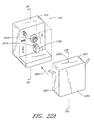
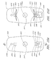
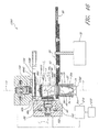
- the fluid handling module further comprises a centrifuge having a centrifuge rotor which is rotatable about a centrifuge axis, and a sample cell located on the rotor.
- the sample cell is rotatable with the rotor about the centrifuge axis.
- the rotor and the sample cell are rotatable to a measurement position in which the sample cell operatively engages the analyte detection system.
- a method for analyzing a bodily fluid comprises attaching a fluid handling module to a reusable fluid handling instrument, wherein the fluid handling module comprises a fluid component separator, a spectroscopic sample cell, and a first fluid passageway.
- the reusable fluid handling instrument comprises an analyte detection system.
- a volume of a bodily fluid is drawn from an extracorporeal fluid conduit into the first fluid passageway.
- the fluid component separator separates a first component from the volume of bodily fluid drawn from the extracorporeal fluid conduit. At least a portion of the first component of the bodily fluid is held in the spectroscopic sample cell.
- the analyte detection system analyzes the first component to determine a concentration of an analyte.
- a fluid handling and analysis system comprising a main analysis and control instrument and a fluid handling module removably engageable with the main instrument.
- the main instrument comprises a spectroscopic bodily fluid analyzer and at least one control element.
- the fluid handling module comprises a spectroscopic sample cell and at least one fluid handling element, and the sample cell is accessible via the fluid handling element.
- the fluid handling element has a control interface configured to engage the control element when the main instrument and the fluid handling module are engaged.
- a fluid handling module that is removably engageable with a bodily fluid analyzer.
- the module comprises a fluid handling network and a spectroscopic analysis cell accessible via the fluid handling network.
- the fluid handling network comprises at least one fluid handling element.
- the fluid handling element comprises at least one control element interface.
- a method for analyzing a bodily fluid includes a step of attaching a fluid handling module to a main analysis and control instrument.
- the fluid handling module comprises at lease one fluid handling element having a control element interface, and a spectroscopic sample cell accessible via the fluid handling element.
- the main instrument comprises a bodily fluid analyzer and at least one control element.
- the method further comprises the steps of engaging the control element interface of at least one fluid handling element with at least one control element of the main instrument and controlling fluid flow between the fluid handling element and the spectroscopic sample cell with the control element.
- a fluid handling module that is removably engageable with a bodily fluid analyzer.
- the module comprises a fluid handling element, and a fluid component separator that is accessible via the fluid handling element and configured to separate at least one component of a bodily fluid transported to the fluid component separator.
- the fluid handling element has at least one control element interface.
- a fluid handling and analysis system comprises a main analysis and control instrument and a fluid handling module that is removably engageable with the main instrument.
- the main instrument comprises a spectroscopic bodily fluid analyzer and at least one control element.
- the fluid handling module comprises a fluid component separator and at least one fluid handling element.
- the fluid component separator is accessible via the fluid handling element.
- the fluid handling element has a control interface configured to engage at least one control element when the main instrument and the fluid handling module are engaged.
- a method for analyzing a bodily fluid comprises the step of attaching a fluid handling module to a main analysis and control instrument.
- the fluid handling module comprises at least one fluid handling clement having a control element interface and a fluid component separator that is accessible via the fluid handling element.
- the main instrument comprises a bodily fluid analyzer and at least one control element.
- the method further comprises the steps of engaging the control element interface of the fluid handling element with the control element of the main instrument, and controlling fluid flow between the fluid handling element and the fluid component separator with the control elements.
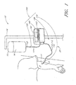
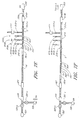
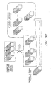
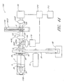
- FIGURE 1 is a schematic of a fluid handling system in accordance with one embodiment
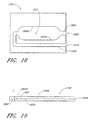
- FIGURE 1A is a schematic of a fluid handling system, wherein a fluid handling and analysis apparatus of the fluid handling system is shown in a cutaway view;
- FIGURE 1B is a cross-sectional view of a bundle of the fluid handling system of FIGURE 1A taken along the line 1B-1B;
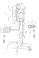
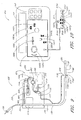
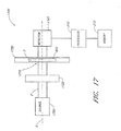
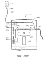
- FIGURE 2 is a schematic of an embodiment of a sampling apparatus
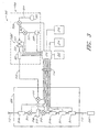
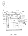
- FIGURE 3 is a schematic showing details of an embodiment of a sampling apparatus
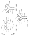
- FIGURE 4 is a schematic of an embodiment of a sampling unit
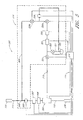
- FIGURE 5 is a schematic of an embodiment of a sampling apparatus
- FIGURE 6A is a schematic of an embodiment of gas injector manifold
- FIGURE 6B is a schematic of an embodiment of gas injector manifold
- FIGURES 7A-7J are schematics illustrating methods of using the infusion and blood analysis system, where FIGURE 7A shows one embodiment of a method of infusing a patient, and FIGURES 7B-7J illustrate steps in a method of sampling from a patient, where FIGURE 7B shows fluid being cleared from a portion of the first and second passageways; FIGURE 7C shows a sample being drawn into the first passageway; FIGURE 7D shows a sample being drawn into second passageway; FIGURE 7E shows air being injected into the sample; FIGURE 7F shows bubbles being cleared from the second passageway; FIGURES 7H and 7I show the sample being pushed part way into the second passageway followed by fluid and more bubbles; and FIGURE 7J shows the sample being pushed to analyzer;
- FIGURE 8 is a perspective front view of an embodiment of a sampling apparatus
- FIGURE 9 is a schematic front view of one embodiment of a sampling apparatus cassette
- FIGURE 10 is a schematic front view of one embodiment of a sampling apparatus instrument
- FIGURE 11 is an illustration of one embodiment of an arterial patient connection
- FIGURE 12 is as illustration of one embodiment of a venous patient connection
- FIGURES 13A, 13B, and 13C are various views of one embodiment of a pinch valve of the present inventions, where FIGURE 13A is a front view, FIGURE 13B is a sectional view, and FIGURE 13C is a sectional view showing one valve in a closed position;
- FIGURES 14A and 14B are various views of one embodiment of a pinch valve, where FIGURE 14A is a front view and FIGURE 14B is a sectional view showing one valve in a closed position;
- FIGURE 15 is a side view of one embodiment of a separator
- FIGURE 16 is an exploded perspective view of the separator of FIGURE 15 ;
- FIGURE 17 is one embodiment of a fluid analysis apparatus
- FIGURE 18 is a top view of a cuvette for use in the apparatus of FIGURE 17 ;
- FIGURE 19 is a side view of the cuvette of FIGURE 18 ;
- FIGURE 20 is an exploded perspective view of the cuvette of FIGURE 18 ;
- FIGURE 21 is a schematic of an embodiment of a sample preparation unit
- FIGURE 22A is a perspective view of another embodiment of a fluid handling and analysis apparatus having a main instrument and removable cassette;
- FIGURE 22B is a partial cutaway, side elevational view of the fluid handling and analysis apparatus with the cassette spaced from the main instrument;
- FIGURE 22C is a cross-sectional view of the fluid handling and analysis apparatus of FIGURE 22A wherein the cassette is installed onto the main instrument;
- FIGURE 23A is a cross-sectional view of the cassette of the fluid handling and analysis apparatus of FIGURE 22A taken along the line 23A-23A;
- FIGURE 23B is a cross-sectional view of the cassette of FIGURE 23A taken along the line 23B-23B of FIGURE 23A ;
- FIGURE 23C is a cross-sectional view of the fluid handling and analysis apparatus having a fluid handling network, wherein a rotor of the cassette is in a generally vertical orientation;
- FIGURE 23D is a cross-sectional view of the fluid handling and analysis apparatus, wherein the rotor of the cassette is in a generally horizontal orientation;
- FIGURE 23E is a front elevational view of the main instrument of the fluid handling and analysis apparatus of FIGURE 23C ;
- FIGURE 24A is a cross-sectional view of the fluid handling and analysis apparatus having a fluid handling network in accordance with another embodiment
- FIGURE 24B is a front elevational view of the main instrument of the fluid handling and analysis apparatus of FIGURE 24A ;
- FIGURE 25A is a front elevational view of a rotor having a sample element for holding sample fluid
- FIGURE 25B is a rear elevational view of the rotor of FIGURE 25A ;
- FIGURE 25C is a front elevational view of the rotor of FIGURE 25A with the sample element filled with a sample fluid;
- FIGURE 25D is a front elevational view of the rotor of FIGURE 25C after the sample fluid has been separated;
- FIGURE 25E is a cross-sectional view of the rotor taken along the line 25E-25E of FIGURE 25A ;
- FIGURE 25F is an enlarged sectional view of the rotor of FIGURE 25E ;
- FIGURE 26A is an exploded perspective view of a sample element for use with a rotor of a fluid handling and analysis apparatus
- FIGURE 26B is a perspective view of an assembled sample element
- FIGURE 27A is a front elevational view of a fluid interface for use with a cassette
- FIGURE 27B is a top elevational view of the fluid interface of FIGURE 27A ;
- FIGURE 27C is an enlarged side view of a fluid interface engaging a rotor
- FIGURE 28 is a cross-sectional view of the main instrument of the fluid handling and analysis apparatus of FIGURE 22A taken along the line 28-28;
- FIGURE 29 is a graph illustrating the absorption spectra of various components that may be present in a blood sample
- FIGURE 30 is a graph illustrating the change in the absorption spectra of blood having the indicated additional components of FIGURE 29 relative to a Sample Population blood and glucose concentration, where the contribution due to water has been numerically subtracted from the spectra;
- FIGURE 31 is an embodiment of an analysis method for determining the concentration of an analyte in the presence of possible interferents
- FIGURE 32 is one embodiment of a method for identifying interferents in a sample for use with the embodiment of FIGURE 31 ;
- FIGURE 33A is a graph illustrating one embodiment of the method of FIGURE 32
- FIGURE 33B is a graph further illustrating the method of FIGURE 32 ;
- FIGURE 34 is a one embodiment of a method for generating a model for identifying possible interferents in a sample for use with an embodiment of FIGURE 31 ;
- FIGURE 35 is a schematic of one embodiment of a method for generating randomly-scaled interferent spectra
- FIGURE 36 is one embodiment of a distribution of interferent concentrations for use with the embodiment of FIGURE 35 ;
- FIGURE 37 is a schematic of one embodiment of a method for generating combination interferent spectra
- FIGURE 38 is a schematic of one embodiment of a method for generating an interferent-enhanced spectral database
- FIGURE 39 is a graph illustrating the effect of interferents on the error of glucose estimation
- FIGURES 40A, 40B , 40C, and 40D each have a graph showing a comparison of the absorption spectrum of glucose with different interferents taken using two different techniques: a Fourier Transform Infrared (FTIR) spectrometer having an interpolated resolution of 1 cm -1 (solid lines with triangles); and by 25 finite-bandwidth IR filters having a Gaussian profile and full-width half-maximum (FWHM) bandwidth of 28 cm -1 corresponding to a bandwidth that varies from 140 nm at 7.08 ⁇ m, up to 279 ⁇ m at 10 ⁇ m (dashed lines with circles).
- FTIR Fourier Transform Infrared
- FIGURE 41 shows a graph of the blood plasma spectra for 6 blood sample taken from three donors in arbitrary units for a wavelength range from 7 ⁇ m to 10 ⁇ m, where the symbols on the curves indicate the central wavelengths of the 25 filters;
- FIGURES 42A, 42B , 42C, and 42D contain spectra of the Sample Population of 6 samples having random amounts of mannitol ( FIGURE 42A ), dextran ( FIGURE 42B ), n-acetyl L cysteine ( FIGURE 42C ), and procainamide ( FIGURE 42D ), at a concentration levels of 1 mg/dL and path lengths of 1 ⁇ m;
- FIGURES 43A-43D are graphs comparing calibration vectors obtained by training in the presence of an interferent, to the calibration vector obtained by training on clean plasma spectra for mannitol ( FIGURE 43A ), dextran ( FIGURE 43B ), n-acetyl L cysteine ( FIGURE 43C ), and procainamide ( FIGURE 43D ) for water-free spectra;
- FIGURE 44 is a schematic illustration of another embodiment of the analyte detection system.
- FIGURE 45 is a plan view of one embodiment of a filter wheel suitable for use in the analyte detection system depicted in FIGURE 44 ;
- FIGURE 46 is a partial sectional view of another embodiment of an analyte detection system.
- FIGURE 47 is a detailed sectional view of a sample detector of the analyte detection system illustrated in FIGURE 46 ;
- FIGURE 48 is a detailed sectional view of a reference detector of the analyse detection system illustrated in FIGURE 46 ;
- FIGURE 49 is an embodiment of an analysis method for analyzing a sample.
- FIGURE 1 illustrates an embodiment of a fluid handling system 10 which can determine the concentration of one or more substances in a sample fluid, such as a whole blood sample from a patient P.
- the fluid handling system 10 can also deliver an infusion fluid 14 to the patient P.
- the fluid handling system 10 is located bedside and generally comprises a container 15 holding the infusion fluid 14 and a sampling system 100 which is in communication with both the container 15 and the patient P.
- the fluid handling system 10 can be in fluid communication with an extracorporeal fluid conduit containing a volume of a bodily fluid.
- a tube 13 extends from the container 15 to the sampling system 100.
- a tube 12 extends from the sampling system 100 to the patient P.
- any suitable extracorporeal fluid conduit such as a catheter, IV tube or an IV network , can be connected to the sampling system 100 with a connector such as the depicted connector 110.
- the extracorporeal fluid conduit need not be attached to the patient P; for example, the extracorporeal fluid conduit can be in fluid communication with a container of the bodily fluid of interest (e.g. blood), or the extracorporeal fluid conduit can serve as a stand-alone volume of the bodily fluid of interest.
- one or more components of the fluid handling system 10 can be located at another facility, room, or other suitable remote location.
- One or more components of the fluid handling system 10 can communicate with one or more other components of the fluid handling system 10 (or with other devices) by any suitable communication means, such as communication interfaces including, but not limited to, optical interfaces, electrical interfaces, and wireless interfaces. These interfaces can be part of a local network, internet, wireless network, or other suitable networks.
- the Infusion fluid 14 can comprise water, saline, dextrose, lactated Ringer's solution, drugs, insulin, mixtures thereof, or other suitable substances.
- the illustrated sampling system 100 allows the infusion fluid to pass to the patient P and/or uses the infusion fluid in the analysis.
- the fluid handling system 10 may not employ infusion fluid. The fluid handling system 10 may thus draw samples without delivering any fluid to the patient P.
- the sampling system 100 can be removably or permanently coupled to the tube 13 and tube 12 via connectors 110, 120.
- the patient connector 110 can selectively control the flow of fluid through a bundle 130, which includes a patient connection passageway 112 and a sampling passageway 113, as shown in FIGURE 1B .
- the sampling system 100 can also draw one or more samples from the patient P by any suitable means.
- the sampling system 100 can perform one or more analyses on the sample, and then returns the sample to the patient or a waste container.
- the sampling system 100 is a modular unit that can be removed and replaced as desired.
- the sampling system 100 can include, but is not limited to, fluid handling and analysis apparatuses, connectors, passageways, catheters, tubing, fluid control elements, valves, pumps, fluid sensors, pressure sensors, temperature sensors, hematocrit sensors, hemoglobin sensors, colorimetric sensors, and gas (or “bubble") sensors, fluid conditioning elements, gas injectors, gas filters, blood plasma separators, and/or communication devices (e.g., wireless devices) to permit the transfer of information within the sampling system or between sampling system 100 and a network.
- the illustrated sampling system 100 has a patient connector 110 and a fluid handling and analysis apparatus 140, which analyzes a sample drawn from the patient P.
- the fluid handling and analysis apparatus 140 and patient connector 110 cooperate to control the flow of infusion fluid into, and/or samples withdrawn from, the patient P. Samples can also be withdrawn and transferred in other suitable manners.
- FIGURE 1A is a close up view of the fluid handling and analysis apparatus 140 which is partially cutaway to reveal some of its internal components.
- the fluid handling and analysis apparatus 140 preferably includes a pump 203 that controls the flow of fluid from the container 15 to the patient P and/or the flow of fluid drawn from the patient P.
- the pump 203 can selectively control fluid flow rates, direction(s) of fluid flow(s), and other fluid flow parameters as desired.
- the term "pump" is a broad term and means, without limitation, a pressurization/pressure device, vacuum device, or any other suitable means for causing fluid flow.
- the pump 203 can include, but is not limited to, a reversible peristaltic pump, two unidirectional pumps that work in concert with valves to provide flow in two directions, a unidirectional pump, a displacement pump, a syringe, a diaphragm pump, roller pump, or other suitable pressurization device.
- the illustrated fluid handling and analysis apparatus 140 has a display 141 and input devices 143.
- the illustrated fluid handling and analysis apparatus 140 can also have a sampling unit 200 configured to analyze the drawn fluid sample.
- the sampling unit 200 can thus receive a sample, prepare the sample, and/or subject the sample (prepared or unprepared) to one or more tests.
- the sampling unit 200 can then analyze results from the tests.
- the sampling unit 200 can include, but is not limited to, separators, filters, centrifuges, sample elements, and/or detection systems, as described in detail below.
- the sampling unit 200 (see FIGURE 3 ) can include an analyte detection system for detecting the concentration of one or more analytes in the body fluid sample.
- the sampling unit 200 can prepare a sample for analysis.
- the fluid handling and analysis apparatus 140 performs an analysis on plasma contained in whole blood taken from the patient P
- filters, separators, centrifuges, or other types of sample preparation devices can be used to separate plasma from other components of the blood.
- the sampling unit 200 can analyze the plasma to determine, for example, the patient P 's glucose level.
- the sampling unit 200 can employ spectroscopic methods, colorimetric methods, electrochemical methods, or other suitable methods for analyzing samples.
- the fluid 14 in the container 15 can flow through the tube 13 and into a fluid source passageway 111.
- the fluid can further flow through the passageway 111 to the pump 203, which can pressurize the fluid.
- the fluid 14 can then flow from the pump 203 through the patient connection passageway 112 and catheter 11 into the patient P.
- the fluid handling and analysis apparatus 140 can draw a sample from the patient P through the catheter 11 to a patient connector 110.
- the patient connector 110 directs the fluid sample into the sampling passageway 113 which leads to the sampling unit 200.
- the sampling unit 200 can perform one or more analyses on the sample.
- the fluid handling and analysis apparatus 140 can then output the results obtained by the sampling unit 200 on the display 141.
- the fluid handling system 10 can draw and analyze body fluid sample(s) from the patient P to provide real-time or near-real-time measurement of glucose levels.
- Body fluid samples can be drawn from the patient P continuously, at regular intervals (e.g., every 5, 10, 15, 20, 30 or 60 minutes), at irregular intervals, or at any time or sequence for desired measurements. These measurements can be displayed bedside with the display 141 for convenient monitoring of the patient P.
- the illustrated fluid handling system 10 is mounted to a stand 16 and can be used in hospitals, ICUs, residences, healthcare facilities, and the like.
- the fluid handling system 10 can be transportable or portable for an ambulatory patient.
- the ambulatory fluid handling system 10 can be coupled (e.g., strapped, adhered, etc.) to a patient, and may be smaller than the bedside fluid handling system 10 illustrated in FIGURE 1 .
- the fluid handling system 10 is an implantable system sized for subcutaneous implantation and can be used for continuous monitoring.
- the fluid handling system 10 is miniaturized so that the entire fluid handling system can be implanted. In other embodiments, only a portion of the fluid handling system 10 is sized for implantation.
- the fluid handling system 10 is a disposable fluid handling system and/or has one or more disposable components.
- the term "disposable" when applied to a system or component (or combination of components), such as a cassette or sample element is a broad term and means, without limitation, that the component in question is used a finite number of times and then discarded. Some disposable components are used only once and then discarded. Other disposable components are used more than once and then discarded.
- the fluid handling and analysis apparatus 140 can have a main instrument and a disposable cassette that can be installed onto the main instrument, as discussed below. The disposable cassette can be used for predetermined length of time, to prepare a predetermined amount of sample fluid for analysis, etc.
- the cassette can be used to prepare a plurality of samples for subsequent analyses by the main instrument.
- the reusable main instrument can be used with any number of cassettes as desired.
- the cassette can be a portable, handheld cassette for convenient transport. In these embodiments, the cassette can be manually mounted to or removed from the main instrument.
- the cassette may be a non disposable cassette which can be permanently coupled to the main instrument, as discussed below.
- Section I discloses various embodiments of the fluid handling system that may be used to transport fluid from a patient for analysis.
- Section II discloses several embodiments of fluid handling methods that may be used with the apparatus discussed in Section I.
- Section III discloses several embodiments of a sampling system that may be used with the apparatus of Section I or the methods of Section II.
- Section IV discloses various embodiments of a sample analysis system that may be used to detect the concentration of one or more analytes in a material sample.
- Section V discloses methods for determining analyte concentrations from sample spectra.
- FIGURE 1 is a schematic of the fluid handling system 10 which includes the container 15 supported by the stand 16 and having an interior that is fillable with the fluid 14, the catheter 11, and the sampling system 100.
- Fluid handling system 10 includes one or more passageways 20 that form conduits between the container, the sampling system, and the catheter.
- sampling system 100 is adapted to accept a fluid supply, such as fluid 14, and to be connected to a patient, including, but not limited to catheter 11 which is used to catheterize a patient P.
- Fluid 14 includes, but is not limited to, fluids for infusing a patient such as saline, lactated Ringer's solution, or water. Sampling system 100, when so connected, is then capable of providing fluid to the patient.
- sampling system 100 is also capable of drawing samples, such as blood, from the patient through catheter 11 and passageways 20, and analyzing at least a portion of the drawn sample.
- Sampling system 100 measures characteristics of the drawn sample including, but not limited to, one or more of the blood plasma glucose, blood urea nitrogen (BUN), hematocrit, hemoglobin, or lactate levels.
- sampling system 100 includes other devices or sensors to measure other patient or apparatus related information including, but not limited to, patient blood pressure, pressure changes within the sampling system, or sample draw rate.
- FIGURE 1 shows sampling system 100 as including the patient connector 110, the fluid handling and analysis apparatus 140, and the connector 120.
- Sampling system 100 may include combinations of passageways, fluid control and measurement devices, and analysis devices to direct, sample, and analyze fluid.
- Passageways 20 of sampling system 100 include the fluid source passageway 111 from connector 120 to fluid handling and analysis apparatus 140, the patient connection passageway 112 from the fluid handling and analysis apparatus to patient connector 110, and the sampling passageway 113 from the patient connector to the fluid handling and analysis apparatus.
- the reference of passageways 20 as including one or more passageway, for example passageways 111, 112, and 113 are provided to facilitate discussion of the system. It is understood that passageways may include one or more separate components and may include other intervening components including, but not limited to, pumps, valves, manifolds, and analytic equipment.
- Passageway is a broad term and is used in its ordinary sense and includes, without limitation except as explicitly stated, as any opening through a material through which a fluid, such as a liquid or a gas, may pass so as to act as a conduit.
- Passageways include, but are not limited to, flexible, inflexible or partially flexible tubes, laminated structures having openings, bores through materials, or any other structure that can act as a conduit and any combination or connections thereof.
- the internal surfaces of passageways that provide fluid to a patient or that are used to transport blood are preferably biocompatible materials, including but not limited to silicone, polyetheretberketone (PEEK), or polyethylene (PE).
- PEEK polyetheretberketone
- PE polyethylene
- One type of preferred passageway is a flexible tube having a fluid contacting surface formed from a biocompatible material.
- a passageway, as used herein, also includes separable portions that, when connected, form a passageway.
- the inner passageway surfaces may include coatings of various sorts to enhance certain properties of the conduit, such as coatings that affect the ability of blood to clot or to reduce friction resulting from fluid flow. Coatings include, but are not limited to, molecular or ionic treatments.
- connection is a broad term and is used in its ordinary sense and includes, without limitation except as explicitly stated, with respect to two or more things (e.g., elements, devices, patients, etc.): a condition of physical contact or attachment, whether direct, indirect (via, e.g., intervening member(s)), continuous, selective, or intermittent; and/or a condition of being in fluid, electrical, or optical-signal communication, whether direct, indirect, continuous, selective (e.g., where there exist one or more intervening valves, fluid handling components, switches, loads, or the like), or intermittent.
- a condition of fluid communication is considered to exist whether or not there exists a continuous or contiguous liquid or fluid column extending between or among the two or more things in question.
- connectors can connect components of the fluid handling system described herein.
- the term "connector” is a broad term and is used in its ordinary sense and includes, without limitation except as explicitly stated, as a device that connects passageways or electrical wires to provide communication (whether direct, indirect, continuous, selective, or intermittent) on either side of the connector.
- Connectors contemplated herein include a device for connecting any opening through which a fluid may pass. These connectors may have intervening valves, switches, fluid handling devices, and the like for affecting fluid flow.
- a connector may also house devices for the measurement, control, and preparation of fluid, as described in several of the embodiments.
- Fluid handling and analysis apparatus 140 may control the flow of fluids through passageways 20 and the analysis of samples drawn from a patient P, as described subsequently.
- Fluid handling and analysis apparatus 140 includes the display 141 and input devices, such as buttons 143.
- Display 141 provides information on the operation or results of an analysis performed by fluid handling and analysis apparatus 140.
- display 141 indicates the function of buttons 143, which are used to input information into fluid handling and analysis apparatus 140.
- Information that may be input into or obtained by fluid handling and analysis apparatus 140 includes, but is not limited to, a required infusion or dosage rate, sampling rate, or patient specific information which may include, but is not limited to, a patient identification number or medical information.
- fluid handling and analysis apparatus 140 obtains information on patient P over a communications network, for example an hospital communication network having patient specific information which may include, but is not limited to, medical conditions, medications being administered, laboratory blood reports, gender, and weight.
- a communications network for example an hospital communication network having patient specific information which may include, but is not limited to, medical conditions, medications being administered, laboratory blood reports, gender, and weight.
- FIGURE 1 shows catheter 11 connected to patient P.
- fluid handling system 10 may catheterize a patient's vein or artery.
- Sampling system 100 is releasably connectable to container 15 and catheter 11.
- FIGURE 1 shows container 15 as including the tube 13 to provide for the passage of fluid to, or from, the container, and catheter 11 as including the tube 12 external to the patient.
- Connector 120 is adapted to join tube 13 and passageway 111.
- Patient connector 110 is adapted to join tube 12 and to provide for a connection between passageways 112 and 113.
- Patient connector 110 may also include one or more devices that control, direct, process, or otherwise affect the flow through passageways 112 and 113.
- one or more lines 114 are provided to exchange signals between patient connector 110 and fluid handling and analysis apparatus 140.
- the lines 114 can be electrical lines, optical communicators, wireless communication channels, or other means for communication.
- sampling system 100 may also include passageways 112 and 113, and lines 114.
- the passageways and electrical lines between apparatus 140 and patient connector 110 are referred to, with out limitation, as the bundle 130.
- fluid handling and analysis apparatus 140 and/or patient connector 110 includes other elements (not shown in FIGURE 1 ) that include, but are not limited to: fluid control elements, including but not limited to valves and pumps; fluid sensors, including but not limited to pressure sensors, temperature sensors, hematocrit sensors, hemoglobin sensors, colorimetric sensors, and gas (or "bubble") sensors; fluid conditioning elements, including but not limited to gas injectors, gas filters, and blood plasma separators; and wireless communication devices to permit the transfer of information within the sampling system or between sampling system 100 and a wireless network.
- fluid control elements including but not limited to valves and pumps
- fluid sensors including but not limited to pressure sensors, temperature sensors, hematocrit sensors, hemoglobin sensors, colorimetric sensors, and gas (or "bubble") sensors
- fluid conditioning elements including but not limited to gas injectors, gas filters, and blood plasma separators
- wireless communication devices to permit the transfer of information within the sampling system or between sampling system 100 and a wireless network.
- patient connector 110 includes devices to determine when blood has displaced fluid 14 at the connector end, and thus provides an indication of when a sample is available for being drawn through passageway 113 for sampling. The presence of such a device at patient connector 110 allows for the operation of fluid handling system 10 for analyzing samples without regard to the actual length of tube 12.
- bundle 130 may include elements to provide fluids, including air, or information communication between patient connector 110 and fluid handling and analysis apparatus 140 including, but not limited to, one or more other passageways and/or wires.
- the passageways and lines of bundle 130 are sufficiently long to permit locating patient connector 110 near patient P, for example with tube 12 having a length of less than 0.1 to 0.5 meters, or preferably approximately 0.15 meters and with fluid handling and analysis apparatus 140 located at a convenient distance, for example on a nearby stand 16.
- bundle 130 is from 0.3 to 3 meters, or more preferably from 1.5 to 2.0 meters in length.
- patient connector 110 and connector 120 include removable connectors adapted for fitting to tubes 12 and 13, respectively.
- container 15 /tube 13 and catheter 11 /tube 12 are both standard medical components, and sampling system 100 allows for the easy connection and disconnection of one or both of the container and catheter from fluid handling system 10.
- tubes 12 and 13 and a substantial portion of passageways 111 and 112 have approximately the same internal cross-sectional area. It is preferred, though not required, that the internal cross-sectional area of passageway 113 is less than that of passageways 111 and 112 (see FIGURE 1B ). As described subsequently, the difference in areas permits fluid handling system 10 to transfer a small sample volume of blood from patient connector 110 into fluid handling and analysis apparatus 140.
- passageways 111 and 112 are formed from a tube having an inner diameter from 0.3 millimeter to 1.50 millimeter, or more preferably having a diameter from 0.60 millimeter to 1.2 millimeter.
- Passageway 113 is formed from a tube having an inner diameter from 0.3 millimeter to 1.5 millimeter, or more preferably having an inner diameter of from 0.6 millimeter to 1.2 millimeter.
- FIGURE 1 shows sampling system 100 connecting a patient to a fluid source
- Alternative embodiments include, but are not limited to, a greater or fewer number of connectors or passageways, or the connectors may be located at different locations within fluid handling system 10, and alternate fluid paths.
- passageways 111 and 112 may be formed from one tube, or may be formed from two or more coupled tubes including, for example, branches to other tubes within sampling system 100, and/or there may be additional branches for infusing or obtaining samples from a patient.
- patient connector 110 and connector 120 and sampling system 100 alternatively include additional pumps and/or valves to control the flow of fluid as described below.
- FIGURES 1A and 2 illustrate a sampling system 100 configured to analyze blood from patient P which may be generally similar to the embodiment of the sampling system illustrated in FIGURE 1 , except as further detailed below. Where possible, similar elements are identified with identical reference numerals in the depiction of the embodiments of FIGURES 1 to 2 .
- FIGURES 1A and 2 show patient connector 110 as including a sampling assembly 220 and a connector 230, portions of passageways 111 and 113, and lines 114, and fluid handling and analysis apparatus 140 as including the pump 203, the sampling unit 200, and a controller 210.
- the pump 203, sampling unit 200, and controller 210 are contained within a housing 209 of the fluid handling and analysis apparatus 140.
- the passageway 111 extends from the connector 120 through the housing 209 to the pump 203.
- the bundle 130 extends from the pump 203, sampling unit 200, and controller 210 to the patient connector 110.
- the passageway 111 provides fluid communication between connector 120 and pump 203 and passageway 113 provides fluid communication between pump 203 and connector 110.
- Controller 210 is in communication with pump 203, sampling unit 200, and sampling assembly 220 through lines 114.
- Controller 210 has access to memory 212, and optionally has access to a media reader 214, including but not limited to a DVD or CD-ROM reader, and communications link 216, which can comprise a wired or wireless communications network, including but not limited to a dedicated line, an intranet, or an Internet connection.
- sampling unit 200 may include one or more passageways, pumps and/or valves, and sampling assembly 220 may include passageways, sensors, valves, and/or sample detection devices.
- Controller 210 collects information from sensors and devices within sampling assembly 220, from sensors and analytical equipment within sampling unit 200, and provides coordinated signals to control pump 203 and pumps and valves, if present, in sampling assembly 220.
- Fluid handling and analysis apparatus 140 includes the ability to pump in a forward direction (towards the patient) and in a reverse direction (away from the patient).
- pump 203 may direct fluid 14 into patient P or draw a sample, such as a blood sample from patient P, from catheter 11 to sampling assembly 220, where it is further directed through passageway 113 to sampling unit 200 for analysis.
- pump 203 provides a forward flow rate at least sufficient to keep the patient vascular line open. In one embodiment, the forward flow rate is from 1 to 5 ml/hr.
- the flow rate of fluid is about 0.05 ml/hr, 0.1 ml/hr, 0.2 ml/hr, 0.4 ml/hr, 0.6 ml/hr, 0.8 ml/hr, 1.0 ml/br, and ranges encompassing such flow rates. In some embodiments, for example, the flow rate of fluid is less than about 1.0 ml/hr. In certain embodiments, the flow rate of fluid may be about 0.1 ml/hr or less.
- fluid handling and analysis apparatus 140 includes the ability to draw a sample from the patient to sampling assembly 220 and through passageway 113.
- pump 203 provides a reverse flow to draw blood to sampling assembly 220, preferably by a sufficient distance past the sampling assembly to ensure that the sampling assembly contains an undiluted blood sample.
- passageway 113 has an inside diameter of from 25 to 200 microns, or more preferably from 50 to 100 microns.
- Sampling unit 200 extracts a small sample, for example from 10 to 100 microliters of blood, or more preferably approximately 40 microliters volume of blood, from sampling assembly 220.
- pump 203 is a directionally controllable pump that acts on a flexible portion of passageway 111.
- Examples of a single, directionally controllable pump include, but are not limited to a reversible peristaltic pump or two unidirectional pumps that work in concert with valves to provide flow in two directions.
- pump 203 includes a combination of pumps, including but not limited to displacement pumps, such as a syringe, and/or valve to provide bi-directional flow control through passageway 111.
- Controller 210 includes one or more processors for controlling the operation of fluid handling system 10 and for analyzing sample measurements from fluid handling and analysis apparatus 140. Controller 210 also accepts input from buttons 143 and provides information on display 141. Optionally, controller 210 is in bi-directional communication with a wired or wireless communication system, for example a hospital network for patient information.
- the one or more processors comprising controller 210 may include one or more processors that are located either within fluid handling and analysis apparatus 140 or that are networked to the unit.
- the control of fluid handling system 10 by controller 210 may include, but is not limited to, controlling fluid flow to infuse a patient and to sample, prepare, and analyze samples.
- the analysis of measurements obtained by fluid handling and analysis apparatus 140 of may include, but is not limited to, analyzing samples based on inputted patient specific information, from information obtained from a database regarding patient specific information, or from information provided over a network to controller 210 used in the analysis of measurements by apparatus 140.
- Fluid handling system 10 provides for the infusion and sampling of a patient blood as follows. With fluid handling system 10 connected to bag 15 having fluid 14 and to a patient P, controller 210 infuses a patient by operating pump 203 to direct the fluid into the patient. Thus, for example, in one embodiment, the controller directs that samples be obtained from a patient by operating pump 203 to draw a sample. In one embodiment, pump 203 draws a predetermined sample volume, sufficient to provide a sample to sampling assembly 220. In another embodiment, pump 203 draws a sample until a device within sampling assembly 220 indicates that the sample has reached the patient connector 110. As an example which is not meant to limit the scope of the present invention, one such indication is provided by a sensor that detects changes in the color of the sample.
- Another example is the use of a device that indicates changes in the material within passageway 111 including, but not limited to, a decrease in the amount of fluid 14, a change with time in the amount of fluid, a measure of the amount of hemoglobin, or an indication of a change from fluid to blood in the passageway.
- controller 210 When the sample reaches sampling assembly 220, controller 210 provides an operating signal to valves and/or pumps in sampling system 100 (not shown) to draw the sample from sampling assembly 220 into sampling unit 200. After a sample is drawn towards sampling unit 200, controller 210 then provides signals to pump 203 to resume infusing the patient. In one embodiment, controller 210 provides signals to pump 203 to resume infusing the patient while the sample is being drawn from sampling assembly 220. In an alternative embodiment, controller 210 provides signals to pump 203 to stop infusing the patient while the sample is being drawn from sampling assembly 220. In another alternative embodiment, controller 210 provides signals to pump 203 to slow the drawing of blood from the patient while the sample is being drawn from sampling assembly 220.
- controller 210 monitors indications of obstructions in passageways or catheterized blood vessels during reverse pumping and moderates the pumping rate and/or direction of pump 203 accordingly.
- obstructions are monitored using a pressure sensor in sampling assembly 220 or along passageways 20.
- controller 210 directs pump 203 to decrease the reverse pumping rate, stop pumping, or pump in the forward direction in an effort to reestablish unobstructed pumping.
- FIGURE 3 is a schematic showing details of a sampling system 300 which may be generally similar to the embodiments of sampling system 100 as illustrated in FIGURES 1 and 2 , except as further detailed below.
- Sampling system 300 includes sampling assembly 220 having, along passageway 112: connector 230 for connecting to tube 12, a pressure sensor 317, a colorimetric sensor 311, a first bubble sensor 314a, a first valve 312, a second valve 313, and a second bubble sensor 314b.
- Passageway 113 forms a "T" with passageway 111 at a junction 318 that is positioned between the first valve 312 and second valve 313, and includes a gas injector manifold 315 and a third valve 316.
- the lines 114 comprise control and/or signal lines extending from colorimetric sensor 311, first, second, and third valves (312, 313, 316), first and second bubble sensors (314a, 314b), gas injector manifold 315, and pressure sensor 317.
- Sampling system 300 also includes sampling unit 200 which has a bubble sensor 321, a sample analysis device 330, a first valve 323a, a waste receptacle 325, a second valve 323b, and a pump 328.
- Passageway 113 forms a "T" to form a waste line 324 and a pump line 327.
- the sensors of sampling system 100 are adapted to accept a passageway through which a sample may flow and that sense through the walls of the passageway. As described subsequently, this arrangement allows for the sensors to be reusable and for the passageways to be disposable. It is also preferred, though not necessary, that the passageway is smooth and without abrupt dimensional changes which may damage blood or prevent smooth flow of blood. In addition, is also preferred that the passageways that deliver blood from the patient to the analyzer not contain gaps or size changes that permit fluid to stagnate and not be transported through the passageway.
- valves 312, 313, 316, and 323 are "pinch valves," in which one or more movable surfaces compress the tube to restrict or stop flow therethrough.
- the pinch valves include one or more moving surfaces that are actuated to move together and "pinch" a flexible passageway to stop flow therethrough. Examples of a pinch valve include, for example, Model PV256 Low Power Pinch Valve (Instech Laboratories, Inc., Plymouth Meeting, PA).
- one or more of valves 312, 313, 316, and 323 may be other valves for controlling the flow through their respective passageways.
- Colorimetric sensor 311 accepts or forms a portion of passageway 111 and provides an indication of the presence or absence of blood within the passageway. In one embodiment, colorimetric sensor 311 permits controller 210 to differentiate between fluid 14 and blood. Preferably, colorimetric sensor 311 is adapted to receive a tube or other passageway for detecting blood. This permits, for example, a disposable tube to be placed into or through a reusable colorimetric sensor. In an alternative embodiment, colorimetric sensor 311 is located adjacent to bubble sensor 314b. Examples of a colorimetric sensor include, for example, an Optical Blood Leak/Blood vs. Saline Detector available from Introtek International (Edgewood, NJ).
- sampling system 300 injects a gas - referred to herein and without limitation as a "bubble" - into passageway 113.
- Sampling system 300 includes gas injector manifold 315 at or near junction 318 to inject one or more bubbles, each separated by liquid, into passageway 113.
- the use of bubbles is useful in preventing longitudinal mixing of liquids as they flow through passageways both in the delivery of a sample for analysis with dilution and for cleaning passageways between samples.
- the fluid in passageway 113 includes, in one embodiment of the invention, two volumes of liquids, such as sample S or fluid 14 separated by a bubble, or multiple volumes of liquid each separated by a bubble therebetween.
- Bubble sensors 314a, 314b and 321 each accept or form a portion of passageway 112 or 113 and provide an indication of the presence of air, or the change between the flow of a fluid and the flow of air, through the passageway.
- bubble sensors include, but are not limited to ultrasonic or optical sensors, that can detect the difference between small bubbles or foam from liquid in the passageway.
- bubble detector is an MEC Series Air Bubble/ Liquid Detection Sensor (Introtek International, Edgewood, NY).
- bubble sensor 314a, 314b, and 321 are each adapted to receive a tube or other passageway for detecting bubbles. This permits, for example, a disposable tube to be placed through a reusable bubble sensor.
- Pressure sensor 317 accepts or forms a portion of passageway 111 and provides an indication or measurement of a fluid within the passageway. When all valves between pressure sensor 317 and catheter 11 are open, pressure sensor 317 provides an indication or measurement of the pressure within the patient's catheterized blood vessel. In one embodiment, the output of pressure sensor 317 is provided to controller 210 to regulate the operation of pump 203. Thus, for example, a pressure measured by pressure sensor 317 above a predetermined value is taken as indicative of a properly working system, and a pressure below the predetermined value is taken as indicative of excessive pumping due to, for example, a blocked passageway or blood vessel.
- controller 210 instructs pump 203 to slow or to be operated in a forward direction to reopen the blood vessel.
- DPT-412 Utah Medical Products, Midvale, UT.
- Sample analysis device 330 receives a sample and performs an analysis.
- device 330 is configured to prepare of the sample for analysis.
- device 330 may include a sample preparation unit 332 and an analyte detection system 334, where the sample preparation unit is located between the patient and the analyte detection system.
- sample preparation occurs between sampling and analysis.
- sample preparation unit 332 may take place removed from analyte detection, for example within sampling assembly 220, or may take place adjacent or within analyte detection system 334.
- analyte is a broad term and is used in its ordinary sense and includes, without limitation, any chemical species the presence or concentration of which is sought in the material sample by an analyte detection system.
- the analyte(s) include, but not are limited to, glucose, ethanol, insulin, water, carbon dioxide, blood oxygen, cholesterol, bilirubin, ketones, fatty acids, lipoproteins, albumin, urea, creatinine, white blood cells, red blood cells, hemoglobin, oxygenated hemoglobin, carboxyhemoglobin, organic molecules, inorganic molecules, pharmaceuticals, cytochrome, various proteins and chromophores, microcalcifications, electrolytes, sodium, potassium, chloride, bicarbonate, and hormones.
- a material sample is a broad term and is used in its ordinary sense and includes, without limitation, any collection of material which is suitable for analysis.
- a material sample may comprise whole blood, blood components (e.g., plasma or serum), interstitial fluid, intercellular fluid, saliva, urine, sweat and/or other organic or inorganic materials, or derivatives of any of these materials.
- whole blood or blood components may be drawn from a patient's capillaries.
- sample preparation unit 332 separates blood plasma from a whole blood sample or removes contaminants from a blood sample and thus comprises one or more devices including, but not limited to, a filter, membrane, centrifuge, or some combination thereof.
- analyte detection system 334 is adapted to analyze the sample directly and sample preparation unit 332 is not required.
- sampling assembly 220 and sampling unit 200 direct the fluid drawn from sampling assembly 220 into passageway 113 into sample analysis device 330.
- FIGURE 4 is a schematic of an embodiment of a sampling unit 400 that permits some of the sample to bypass sample analysis device 330.
- Sampling unit 400 may be generally similar to sampling unit 200, except as further detailed below.
- Sampling unit 400 includes bubble sensor 321, valve 323, sample analysis device 330, waste line 324, waste receptacle 325, valve 326, pump line 327, pump 328, a valve 322, and a waste line 329.
- Waste line 329 includes valve 322 and forms a "T" at pump line 337 and waste line 329.
- Valves 316, 322, 323, and 326 permit a flow through passageway 113 to be routed through sample analysis device 330, to be routed to waste receptacle 325, or to be routed through waste line 324 to waste receptacle 325.
- FIGURE 5 is a schematic of one embodiment of a sampling system 500 which may be generally similar to the embodiments of sampling system 100 or 300 as illustrated in FIGURES 1 through 4 , except as further detailed below.
- Sampling system 500 includes an embodiment of a sampling unit 510 and differs from sampling system 300 in part, in that liquid drawn from passageway 111 may be returned to passageway 111 at a junction 502 between pump 203 and connector 120.
- sampling unit 510 includes a return line 503 that intersects passageway 111 on the opposite side of pump 203 from passageway 113, a bubble sensor 505 and a pressure sensor 507, both of which are controlled by controller 210.
- Bubble sensor 505 is generally similar to bubble sensors 314a, 314b and 321 and pressure sensor 507 is generally similar to pressure sensor 317.
- Pressure sensor 507 is useful in determining the correct operation of sampling system 500 by monitoring pressure in passageway 111.
- the pressure in passageway 111 is related to the pressure at catheter 11 when pressure sensor 507 is in fluid communication with catheter 11 (that is, when any intervening valve(s) are open).
- the output of pressure sensor 507 is used in a manner similar to that of pressure sensor 317 described previously in controlling pumps of sampling system 500.
- Sampling unit 510 includes valves 501, 326a, and 326b under the control of controller 210.
- Valve 501 provides additional liquid flow control between sampling unit 200 and sampling unit 510.
- Pump 328 is preferably a bi-directional pump that can draw fluid from and into passageway 113. Fluid may either be drawn from and returned to passageway 501, or may be routed to waste receptacle 325. Valves 326a and 326b are situated on either side of pump 328. Fluid can be drawn through passageway 113 and into return line 503 by the coordinated control of pump 328 and valves 326a and 326b. Directing flow from return line 503 can be used to prime sampling system 500 with fluid.
- liquid may be pulled into sampling unit 510 by operating pump 328 to pull liquid from passageway 113 while valve 326a is open and valve 326b is closed.
- Liquid may then be pumped back into passageway 113 by operating pump 328 to push liquid into passageway 113 while valve 326a is closed and valve 326b is open.
- FIGURE 6A is a schematic of an embodiment of gas injector manifold 315 which may be generally similar or included within the embodiments illustrated in FIGURES 1 through 5 , except as further detailed below.
- Gas injector manifold 315 is a device that injects one or more bubbles in a liquid within passageway 113 by opening valves to the atmosphere and lowering the liquid pressure within the manifold to draw in air. As described subsequently, gas injector manifold 315 facilitates the injection of air or other gas bubbles into a liquid within passageway 113.
- Gas injector manifold 315 has three gas injectors 610 including a first injector 610a, a second injector 610b, and a third injector 610c.
- Each injector 610 includes a corresponding passageway 611 that begins at one of several laterally spaced locations along passageway 113 and extends through a corresponding valve 613 and terminates at a corresponding end 615 that is open to the atmosphere.
- a filter is placed in end 615 to filter out dust or particles in the atmosphere.
- each injector 610 is capable of injecting a bubble into a liquid within passageway 113 by opening the corresponding valve 613, closing a valve on one end of passageway 113 and operating a pump on the opposite side of the passageway to lower the pressure and pull atmospheric air into the fluid.
- passageways 113 and 611 are formed within a single piece of material (e.g., as bores formed in or through a plastic or metal housing (not shown)).
- gas injector manifold 315 includes fewer than three injectors, for example one or two injectors, or includes more than three injectors.
- gas injector manifold 315 includes a controllable high pressure source of gas for injection into a liquid in passageway 113. It is preferred that valves 613 are located close to passageway 113 to minimize trapping of fluid in passageways 611.
- gas injected into passageways 20 should be prevented from reaching catheter 11.
- one embodiment prevents gas from flowing towards catheter 11 by the use of bubble sensor 314a as shown, for example, in FIGURE 3 . If bubble sensor 314a detects gas within passageway 111, then one of several alternative embodiments prevents unwanted gas flow. In one embodiment, flow in the vicinity of sampling assembly 220 is directed into line 113 or through line 113 into waste receptacle 325.
- valves 316 and 323a are opened, valve 313 and the valves 613a, 613b and 613c of gas injector manifold 315 are closed, and pump 328 is turned on to direct flow away from the portion of passageway 111 between sampling assembly 220 and patient P into passageway 113.
- Bubble sensor 321 is monitored to provide an indication of when passageway 113 clears out.
- Valve 313 is then opened, valve 312 is closed, and the remaining portion of passageway 111 is then cleared. Alternatively, all flow is immediately halted in the direction of catheter 11, for example by closing all valves and stopping all pumps.
- a gas-permeable membrane is located within passageway 113 or within gas injector manifold 315 to remove unwanted gas from fluid handling system 10, e.g., by venting such gas through the membrane to the atmosphere or a waste receptacle.
- FIGURE 6B is a schematic of an embodiment of gas injector manifold 315' which may be generally similar to, or included within, the embodiments illustrated in FIGURES 1 through 6A , except as further detailed below.
- gas injector manifold 315' air line 615 and passageway 113 intersect at junction 318. Bubbles are injected by opening valve 316 and 613 while drawing fluid into passageway 113. Gas injector manifold 315' is thus more compact that gas injector manifold 315, resulting in a more controllable and reliable gas generator.
- FIGURES 7A-7J One embodiment of a method of using fluid handling system 10, including sampling assembly 220 and sampling unit 200 of FIGURES 2 , 3 and 6A , is illustrated in Table 1 and in the schematic fluidic diagrams of FIGURES 7A-7J .
- the pumps and valves are controlled to infuse a patient, to extract a sample from the patient up passageway 111 to passageway 113, and to direct the sample along passageway 113 to device 330.
- the pumps and valves are controlled to inj ect bubbles into the fluid to isolate the fluid from the diluting effect of previous fluid and to clean the lines between sampling.
- the valves in FIGURES 7A-7J are labeled with suffices to indicate whether the valve is open or closed. Thus a valve "x,” for example, is shown as valve “x-o" if the valve is open and “x-c" if the valve is closed.
- FIGURE 7A illustrates one embodiment of a method of infusing a patient.
- pump 203 is operated forward (pumping towards the patient)
- pump 328 is off, or stopped
- valves 313 and 312 are open
- valves 613a, 613b, 613c, 316, 323a, and 323b are closed.
- fluid 14 is provided to patient P.
- all of the other passageways at the time of the step of FIGURE 7A substantially contain fluid 14.
- FIGURE 7B illustrates a first sampling step, where liquid is cleared from a portion of patient confection passageway and sampling passageways 112 and 113.
- pump 203 is operated in reverse (pumping away from the patient), pump 328 is off, valve 313 is open, one or more of valves 613a, 613b, and 613c are open, and valves 312, 316, 323a, and 326b are closed.
- air 701 is drawn into sampling passageway 113 and back into patient connection passageway 112 until bubble sensor 314b detects the presence of the air.
- FIGURE 7C illustrates a second sampling step, where a sample is drawn from patient P into patient connection passageway 112.
- pump 203 is operated in reverse, pump 328 is off, valves 312 and 313 are open, and valves 316, 613a, 613b, 613c, 323a, and 323b are closed.
- a sample S is drawn into passageway 112, dividing air 701 into air 701a within sampling passageway 113 and air 701b within the patient connection passageway 112, Preferably this step proceeds until sample S extends just past the junction of passageways 112 and 113.
- the step of FIGURE 7C proceeds until variations in the output of colorimetric sensor 311 indicate the presence of a blood (for example by leveling off to a constant value), and then proceeds for an additional set amount of time to ensure the presence of a sufficient volume of sample S.
- FIGURE 7D illustrates a third sampling step, where a sample is drawn into sampling passageway 113.
- pump 203 is off, or stopped, pump 328 is on, valves 312, 316, and 326b are open, and valves 313, 613a, 613b, 613c and 323a are closed.
- blood is drawn into passageway 113.
- pump 328 is operated to pull a sufficient amount of sample S into passageway 113.
- pump 328 draws a sample S having a volume from 30 to 50 microliters.
- the sample is drawn into both passageways 112 and 113.
- Pump 203 is operated in reverse, pump 328 is on, valves 312, 313, 316, and 323b are open, and valves 613a, 613b, 613c and 323a are closed to ensure fresh blood in sample S.
- FIGURE 7E illustrates a fourth sampling step, where air is injected into the sample. Bubbles which span the cross-sectional area of sampling passageway 113 are useful in preventing contamination of the sample as it is pumped along passageway 113.
- pump 203 is off, or stopped
- pump 328 is on
- valves 316, and 323b are open
- valves 312, 313 and 323a are closed
- valves 613a, 613b, 613c are each opened and closed sequentially to draw in three separated bubbles.
- the pressure in passageway 113 falls below atmospheric pressure and air is drawn into passageway 113.
- valves 613a, 613b, 613c may be opened simultaneously for a short period of time, generating three spaced bubbles.
- injectors 610a, 610b, and 610c inject bubbles 704, 703, and 702, respectively, dividing sample S into a forward sample S1, a middle sample S2, and a rear sample S3.
- FIGURE 7F illustrates a fifth sampling step, where bubbles are cleared from patient connection passageway 112.
- pump 203 is operated in a forward direction
- pump 328 is off
- valves 313, 316, and 323a are open
- valves 312, 613a, 613b, 613c, and 323b are closed.
- the previously injected air 701b is drawn out of first passageway 111 and into second passageway 113.
- This step proceeds until air 701b is in passageway 113.
- FIGURE 7G illustrates a sixth sampling step, where blood in passageway 112 is returned to the patient.
- pump 203 is operated in a forward direction, pump 328 is off, valves 312 and 313 are open, and valves 316, 323a, 613a, 613b, 613c and 323b are closed. With these operating conditions, the previously injected air remains in passageway 113 and passageway 111 is filled with fluid 14.
- FIGURES 7H and 7I illustrates a seventh and eighth sampling steps, where the sample is pushed part way into passageway 113 followed by fluid 14 and more bubbles.
- pump 203 is operated in a forward direction
- pump 328 is off
- valves 313, 316, and 323a are open
- valves 312, 613a, 613b, 613c, and 323b are closed.
- sample S is moved partway into passageway 113 with bubbles injected, either sequentially or simultaneously, into fluid 14 from injectors 610a, 610b, and 610c.
- the pumps and valves are operated as in the step of FIGURE 7E , and fluid 14 is divided into a forward solution C1, a middle solution C2, and a rear solution C3 separated by bubbles 705, 706, and 707.
- FIGURE 7J The last step shown in FIGURE 7 is FIGURE 7J , where middle sample S2 is pushed to sample analysis device 330.
- pump 203 is operated in a forward direction, pump 328 is off, valves 313, 316, and 323a are open, and valves 312, 613a, 613b, 613c, and 323b are closed.
- the sample is pushed into passageway 113.
- bubble sensor 321 detects bubble 702
- pump 203 continues pumping until sample S2 is taken into device sample analysis 330. Additional pumping using the settings of the step of FIGURE 7J permits the sample S2 to be analyzed and for additional bubbles and solutions to be pushed into waste receptacle 325, cleansing passageway 113 prior to accepting a next sample.
- FIGURE 8 is a perspective front view of a third embodiment of a sampling system 800 which may be generally similar to sampling system 100, 300 or 500 and the embodiments illustrated in FIGURES 1 through 7 , except as further detailed below.
- the fluid handling and analysis apparatus 140 of sampling system 800 includes the combination of an instrument 810 and a sampling system cassette 820.
- FIGURE 8 illustrates instrument 810 and cassette 820 partially removed from each other.
- Instrument 810 includes controller 210 (not shown), display 141 and input devices 143, a cassette interface 811, and lines 114.
- Cassette 820 includes passageway 111 which extends from connector 120 to connector 230, and further includes passageway 113, a junction 829 of passageways 111 and 113, an instrument interface 821, a front surface 823, an inlet 825 for passageway 111, and an inlet 827 for passageways 111 and 113.
- sampling assembly 220 is formed from a sampling assembly instrument portion 813 having an opening 815 for accepting junction 829.
- the interfaces 811 and 821 engage the components of instrument 810 and cassette 820 to facilitate pumping fluid and analyzing samples from a patient, and sampling assembly instrument portion 813 accepts junction 829 in opening 815 to provide for sampling from passageway 111.
- FIGURES 9 and 10 are front views of a sampling system cassette 820 and instrument 810, respectively, of a sampling system 800.
- Cassette 820 and instrument 810 when assembled, form various components of FIGURES 9 and 10 that cooperate to form an apparatus consisting of sampling unit 510 of FIGURE 5 , sampling assembly 220 of FIGURE 3 , and gas injection manifold 315' of FIGURE 6B .
- cassette 820 includes passageways 20 including: passageway 111 having portions 111a, 112a, 112b, 112c, 112d, 112e, and 112f; passageway 113 having portions 113a, 113b, 113c, 113d, 113e, and 113f; passageway 615; waste receptacle 325; disposable components of sample analysis device 330 including, for example, a sample preparation unit 332 adapted to allow only blood plasma to pass therethrough and a sample chamber 903 for placement within analyte detection system 334 for measuring properties of the blood plasma; and a displacement pump 905 having a piston control 907.
- instrument 810 includes bubble sensor units 1001a, 1001b, and 1001c, colorimetric sensor, which is a hemoglobin sensor unit 1003, a peristaltic pump roller 1005a and a roller support 1005b, pincher pairs 1007a, 1007b, 1007c, 1007d, 1007e, 1007f, 1007g, and 1007h, an actuator 1009, and a pressure sensor unit 1011.
- instrument 810 includes portions of sample analysis device 330 which are adapted to measure a sample contained within sample chamber 903 when located near or within a probe region 1002 of an optical analyte detection system 334.
- Pump 203 is formed from portion 111a placed between peristaltic pump roller 1005a and roller support 1005b to move fluid through passageway 111 when the roller is actuated; valves 501, 323, 326a, and 326b are formed with pincher pairs 1007a, 1007b, 1007c, and 1007d surrounding portions 113a, 113c, 113d, and 113e, respectively, to permit or block fluid flow therethrough.
- Pump 328 is formed from actuator 1009 positioned to move piston control 907. It is preferred that the interconnections between the components of cassette 820 and instrument 810 described in this paragraph are made with one motion. Thus for example the placement of interfaces 811 and 821 places the passageways against and/or between the sensors, actuators, and other components.
- the assembly of apparatus 800 includes assembling sampling assembly 220. More specifically, an opening 815a and 815b are adapted to receive passageways 111 and 113, respectively, with junction 829 within sampling assembly instrument portion 813.
- valves 313 and 312 are formed when portions 112b and 112c are placed within pinchers of pinch valves 1007e and 1007f, respectively, bubble sensors 314b and 314a are formed when bubble sensor units 1001b, and 1001c are in sufficient contact with portions 112a and 112d, respectively, to determine the presence of bubbles therein; hemoglobin detector is formed when hemoglobin sensor 1003 is in sufficient contact with portion 112e, and pressure sensor 317 is formed when portion 112f is in sufficient contact with pressure sensor unit 1011 to measure the pressure of a fluid therein.
- valves 316 and 613 are formed when portions 113f and 615 are placed within pinchers of pinch valves 1007h and 1007g, respectively.
- the assembled main instrument 810 and cassette 820 of FIGURES 9-10 can function as follows.
- the system can be considered to begin in an idle state or infusion mode in which the roller pump 1005 operates in a forward direction (with the impeller 1005a turning counterclockwise as shown in FIGURE 10 ) to pump infusion fluid from the container 15 through the passageway 111 and the passageway 112, toward and into the patient P .
- the pump 1005 delivers infusion fluid to the patient at a suitable infusion rate as discussed elsewhere herein.
- the single air injector of FIGURE 9 (extending from the junction 829 to end 615, opposite the passageway 813) functions in place of the manifold shown in FIGURES 7A-7J .
- the pump 1005 operates in a sample draw mode, by operating in a reverse direction and pulling a sample of bodily fluid (e.g. blood) from the patient into the passageway 112 through the connector 230.
- the sample is drawn up to the hemoglobin sensor 1003, and is preferably drawn until the output of the sensor 1003 reaches a desired plateau level indicating the presence of an undiluted blood sample in the passageway 112 adjacent the sensor 1003.
- the pumps 905, 1005, valves 1007e, 1007f, 1007g, 1007h, bubble sensors 1001b, 1001c and/or hemoglobin sensor 1003 can be operated to move a series of air bubbles and sample-fluid columns into the passageway 113, in a manner similar to that shown in FIGURES 7D-7F .
- the pump 905, in place of the pump 328, is operable by moving the piston control 907 of the pump 905 in the appropriate direction (to the left or right as shown in FIGURES 9-10 ) with the actuator 1009.
- valve 1007h can be closed, and the remainder of the initial drawn sample or volume of bodily fluid in the passageway 112 can be returned to the patient, by operating the pump 1005 in the forward or infusion direction until the passageway 112 is again filled with infusion fluid.
- the sample preparation unit 332 in the depicted embodiment a filter or membrane; alternatively a centrifuge as discussed in greater detail below.
- the unit 332 in the depicted embodiment a filter or membrane; alternatively a centrifuge as discussed in greater detail below.
- the analysis is conducted to determine a level or concentration of one or more analytes, such as glucose, lactate, carbon dioxide, blood urea nitrogen, hemoglobin, and/or any other suitable analytes as discussed elsewhere herein.
- analyte detection system 1700 is spectroscopic (e.g. the system 1700 of FIGURES 17 or 44-46 )
- a spectroscopic analysis of the component(s) or whole fluid is conducted.
- the body fluid sample within the passageway 113 is moved into the waste receptacle 325.
- the pump 905 is operated via the actuator 1009 to push the body fluid, behind a column of saline or infusion fluid obtained via the passageway 909, back through the sample chamber 903 and sample preparation unit 332, and into the receptacle 325.
- the chamber 903 and unit 332 are back-flushed and filled with saline or infusion fluid while the bodily fluid is delivered to the waste receptacle.
- a second analysis can be made on the saline or infusion fluid now in the chamber 903, to provide a "zero" or background reading.
- the fluid handling network of FIGURE 9 other than the waste receptacle 325, is empty of bodily fluid, and the system is ready to draw another bodily fluid sample for analysis.
- FIGURES 13A and 13B are front view and sectional view, respectively, of a first embodiment pinch valve 1300 in an open configuration that can direct flow either one or both of two branches, or legs, of a passageway.
- Pinch valve 1300 includes two separately controllable pinch valves acting on a "Y" shaped passageway 1310 to allow switch of fluid between various legs.
- the internal surface of passageway 1310 forms a first leg 1311 having a flexible pinch region 1312, a second leg 1313 having a flexible pinch region 1314, and a third leg 1315 that joins the first and second legs at an intersection 1317.
- a first pair of pinch valve pinchers 1320 is positioned about pinch region 1312 and a second pair of pinch valve pinchers 1330 is positioned about pinch region 1314.
- Each pair of pinch valve pinchers 1320 and 1330 is positioned on opposite sides of their corresponding pinch regions 1312, 1314 and perpendicular to passageway 1310, and are individually controllable by controller 210 to open and close, that is allow or prohibit fluid communication across the pinch regions.
- controller 210 to open and close, that is allow or prohibit fluid communication across the pinch regions.
- FIGURE 13B shows the first and second pair of pinch valve pinchers 1320, 1330 in an open configuration.
- FIGURE 13C is a sectional view showing the pair of pinch valve pinchers 1320 brought together, thus closing off a portion of first leg 1311 from the second and third legs 1313 , 1315.
- volume 1321 associated with first leg 1311 that is not isolated (“dead space"). It is preferred that dead space is minimized so that fluids of different types can be switched between the various legs of the pinch valve.
- the dead space is reduced by placing the placing the pinch valves close to the intersection of the legs.
- the dead space is reduced by having passageway walls of varying thickness. Thus, for example, excess material between the pinch valves and the intersection will more effectively isolate a valved leg by displacing a portion of volume 1321.
- pinchers 1320 and 1330 are positioned to act as valve 323 and 326 , respectively.
- FIGURES 14A and 14B are various views of a second embodiment pinch valve 1400, where FIGURE 14A is a front view and FIGURE 14B is a sectional view showing one valve in a closed position.
- Pinch valve 1400 differs from pinch valve 1300 in that the pairs of pinch valve pinchers 1320 and 1330 are replaced by pinchers 1420 and 1430 , respectively, that are aligned with passageway 1310 .
- pinch valves includes 2, 3, 4, or more passageway segments that meet at a common junction, with pinchers located at one or more passageways near the junction.
- FIGURES 11 and 12 illustrate various embodiment of connector 230 which may also form or be attached to disposable portions of cassette 820 as one embodiment of an arterial patient connector 1100 and one embodiment a venous patient connector 1200.
- Connectors 1100 and 1200 may be generally similar to the embodiment illustrated in FIGURES 1-10 , except as further detailed below.
- arterial patient connector 1100 includes a stopcock 1101 , a first tube portion 1103 having a length X , a blood sampling port 1105 to acquire blood samples for laboratory analysis, and fluid handling and analysis apparatus 140, a second tube 1107 having a length Y , and a tube connector 1109 .
- Arterial patient connector 1100 also includes a pressure sensor unit 1102 that is generally similar to pressure sensor unit 1011 , on the opposite side of sampling assembly 220.
- Length X is preferably from to 6 inches (0.15 meters) to 50 inches (1.27 meters) or approximately 48 inches (1.2 meters) in length.
- Length Y is preferably from 1 inch (25 millimeters) to 20 inches (0.5 meters), or approximately 12 inches (0.3 meters) in length.
- venous patient connector 1200 includes a clamp 1201, injection port 1105 , and tube connector 1109 .
- analysis is performed on blood plasma.
- the blood plasma must be separated from the whole blood obtained from the patient.
- blood plasma may be obtained from whole blood at any point in fluid handling system 10 between when the blood is drawn, for example at patient connector 110 or along passageway 113 , and when it is analyzed.
- separators and analyte detection systems which may form part of system 10.
- the separators discussed in the present specification can, in certain embodiments, comprise fluid component separators.
- the term "fluid component separator” is a broad term and is used in its ordinary sense and includes, without limitation, any device that is operable to separate one or more components of a fluid to generate two or more unlike substances.
- a fluid component separator can be operable to separate a sample of whole blood into plasma and non-plasma components, and/or to separate a solid-liquid mix (e.g. a solids-contaminated liquid) into solid and liquid components.
- a fluid component separator need not achieve complete separation between or among the generated unlike substances.
- Fluid component separators include filters, membranes, centrifuges, electrolytic devices, or components of any of the foregoing. Fluid component separators can be "active" in that they are operable to separate a fluid more quickly than is possible through the action of gravity on a static, "standing" fluid.
- Section IV.A below discloses a filter which can be used as a blood separator in certain embodiments of the apparatus disclosed herein.
- Section IV.B below discloses an analyte detection system which can be used in certain embodiments of the apparatus disclosed herein.
- Section IV.C below discloses a sample element which can be used in certain embodiments of the apparatus disclosed herein.
- Section IV.D discloses a centrifuge and sample chamber which can be used in certain embodiments of the apparatus disclosed herein.
- sample preparation unit 332 is shown as a blood filter 1500, as illustrated in FIGURES 15 and 16 , where FIGURE 15 is a side view of one embodiment of a filter, and FIGURE 16 is an exploded perspective view of the filter.
- filter 1500 that includes a housing 1501 with an inlet 1503 , a first outlet 1505 and a second outlet 1507 .
- Housing 1501 contains a membrane 1509 that divides the internal volume of housing 1501 into a first volume 1502 that include inlet 1503 and first outlet 1505 and a second volume 1504 .
- FIGURE 16 shows one embodiment of filter 1500 as including a first plate 1511 having inlet 1503 and outlet 1505, a first spacer 1513 having an opening forming first volume 1502, a second spacer 1515 having an opening forming second volume 1504, and a second plate 1517 having outlet 1507.
- Filter 1500 provides for a continuous filtering of blood plasma from whole blood.
- the membrane filters blood cells and blood plasma passes through second outlet 1507.
- the inlet 1503 and first outlet 1505 may be configured to provide the transverse flow across membrane 1509.
- membrane 1509 is a thin and strong polymer film.
- the membrane filter may be a 10 micron thick polyester or polycarbonate film.
- the membrane filter has a smooth glass-like surface, and the holes are uniform, precisely sized, and clearly defined.
- the material of the film may be chemically inert and have low protein binding characteristics.
- membrane 1509 is with a Track Etching process.
- the "raw" film is exposed to charged particles in a nuclear reactor, which leaves “tracks” in the film.
- the tracks may then be etched through the film, which results in holes that are precisely sized and uniformly cylindrical.
- GE Osmonics, Inc. (4636 Somerton Rd. Trevose, PA 19053-6783) utilizes a similar process to manufacture a material that adequately serves as the membrane filter.
- the surface the membrane filter depicted above is a GE Osmonics Polycarbonate TE film.
- the plasma from 3 cc of blood may be extracted using a polycarbonate track etch film ("PCTE") as the membrane filter.
- PCTE polycarbonate track etch film
- the PCTE may have a pore size of 2 ⁇ m and an effective area of 170 millimeter 2 .
- the tubing connected to the supply, exhaust and plasma ports has an internal diameter of 1 millimeter.
- 100 ⁇ l of plasma can be initially extracted from the blood. After saline is used to rinse the supply side of the cell, another 100 ⁇ l of clear plasma can be extracted.
- the rate of plasma extraction in this method and configuration can be about 15-25 ⁇ l/min.
- Using a continuous flow mechanism to extract plasma may provide several benefits.
- the continuous flow mechanism is reusable with multiple samples, and there is negligible sample carryover to contaminate subsequent samples.
- One embodiment may also eliminate most situations in which plugging may occur.
- a preferred configuration provides for a low internal volume.
- analyte detection system 334 which is not meant to limit the scope of the present invention, is shown in FIGURE 17 as an optical analyte detection system 1700 .
- Analyte detection system 1700 is adapted to measure spectra of blood plasma.
- the blood plasma provided to analyte detection system 334 may be provided by sample preparation unit 332, including but not limited to a filter 1500 .
- Analyte detection system 1700 comprises an energy source 1720 disposed along a major axis X of system 1700. When activated, the energy source 1720 generates an energy beam E which advances from the energy source 1720 along the major axis X .
- the energy source 1720 comprises an infrared source and the energy beam E comprises an infrared energy beam.
- Probe region 1710 is portion of apparatus 322 in the path of an energized beam E that is adapted to accept a material sample S .
- probe region 1710 is adapted to accept a sample element or cuvette 1730, which supports or contains the material sample S.
- sample element 1730 is a portion of passageway 113, such as a tube or an optical cell. After passing through the sample clement 1730 and the sample S, the energy beam E reaches a detector 1745.
- sample element is a broad term and is used in its ordinary sense and includes, without limitation, structures that have a sample chamber and at least one sample chamber wall, but more generally includes any of a number of structures that can hold, support or contain a material sample and that allow electromagnetic radiation to pass through a sample held, supported or contained thereby; e.g., a cuvette, test strip, etc.
- sample element 1730 forms a disposable portion of cassette 820, and the remaining portions of system 1700 form portions of instrument 810 , and probe region 1710 is probe region 1002 .
- the detector 1745 responds to radiation incident thereon by generating an electrical signal and passing the signal to processor 210 for analysis. Based on the signal(s) passed to it by the detector 1745, the processor computes the concentration of the analyte(s) of interest in the sample S , and/or the absorbance/transmittance characteristics of the sample S at one or more wavelengths or wavelength bands employed to analyze the sample.
- the processor 210 computes the concentration(s), absorbatice(s), transmittance(s), etc. by executing a data processing algorithm or program instructions residing within memory 212 accessible by the processor 210.
- the filter 1725 may comprise a varying-passband filter, to facilitate changing, over time and/or during a measurement taken with apparatus 322, the wavelength or wavelength band of the energy beam E that may pass the filter 1725 for use in analyzing the sample S .
- a varying-passband filter usable with apparatus 322 include, but are not limited to, a filter wheel (discussed in further detail below), an electronically tunable filter, such as those manufactured by Aegis Semiconductor (Woburn, MA), a custom filter using an "Active Thin Films platform," a Fabry-Perot interferometer, such as those manufactured by Scientific Solutions, Inc.
- LCFP liquid crystal Fabry-Perot
- a tunable monochrometer such as a HORIBA (Jobin Yvon, Inc. (Edison, NJ) H1034 type with 7-10 ⁇ m grating, or a custom designed system.
- filter 1725 comprises a varying-passband filter, to facilitate changing, over time and/or during a measurement taken with the detection system 1700 , the wavelength or wavelength band of the energy beam E that may pass the filter 25 for use in analyzing the sample S.
- the energy beam E is filtered with a varying-passband filter, the absorption/transmittance characteristics of the sample S can be analyzed at a number of wavelengths or wavelength bands in a separate, sequential manner. As an example, assume that it is desired to analyze the sample S at N separate wavelengths (Wavelength 1 through Wavelength N).
- the varying-passband filter is first operated or tuned to permit the energy beam E to pass at Wavelength 1, while substantially blocking the beam E at most or all other wavelengths to which the detector 1745 is sensitive (including Wavelengths 2-N).
- the absoiption/transmittance properties of the sample S are then measured at Wavelength 1, based on the beam E that passes through the sample S and reaches the detector 1745.
- the varying-passband filter is then operated or tuned to permit the energy beam E to pass at Wavelength 2, while substantially blocking other wavelengths as discussed above; the sample S is then analyzed at Wavelength 2 as was done at Wavelength 1. This process is repeated until all of the wavelengths of interest have been employed to analyze the sample S.
- the collected absorption/transmittance data can then be analyzed by the processor 210 to determine the concentration of the analyte(s) of interest in the material sample S .
- the measured spectra of sample S is referred to herein in general as C s ( ⁇ i ), that is, a wavelength dependent spectra in which C s is, for example, a transmittance, an absorbance, an optical density, or some other measure of the optical properties of sample S having values at or about a number of wavelengths ⁇ i , where i ranges over the number of measurements taken.
- the measurement C s ( ⁇ i ) is a linear array of measurements that is alternatively written as Cs i .
- the spectral region of system 1700 depends on the analysis technique and the analyte and mixtures of interest.
- one useful spectral region for the measurement of glucose in blood using absorption spectroscopy is the mid-IR (for example, about 4 microns to about 11 microns).
- energy source 1720 produces a beam E having an output in the range of about 4 microns to about 11 microns.
- water is the main contributor to the total absorption across this spectral region, the peaks and other structures present in the blood spectrum from about 6.8 microns to 10.5 microns are due to the absorption spectra of other blood components.
- the 4 to 11 micron region has been found advantageous because glucose has a strong absorption peak structure from about 8.5 to 10 microns, whereas most other blood constituents have a low and flat absorption spectrum in the 8.5 to 10 micron range.
- the main exceptions are water and hemoglobin, both of which are interferents in this region.
- the amount of spectral detail provided by system 1700 depends on the analysis technique and the analyte and mixture of interest. For example, the measurement of glucose in blood by mid-IR absorption spectroscopy is accomplished with from 11 to 25 filters within a spectral region.
- energy source 1720 produces a beam E having an output in the range of about 4 microns to about 11 microns, and filter 1725 include a number of narrow band filters within this range, each allowing only energy of a certain wavelength or wavelength band to pass therethrough.
- filter 1725 includes a filter wheel having 11 filters with a nominal wavelength approximately equal to one of the following 3 ⁇ m, 4.06 ⁇ m, 4.6 ⁇ m, 4.9 ⁇ m, 5.25 ⁇ m, 6.12 ⁇ m, 6.47 ⁇ m, 7.98 ⁇ m, 8.35 ⁇ m, 9.65 ⁇ m, and 12.2 ⁇ m.
- individual infrared filters of the filter wheel are multicavity, narrow band dielectric stacks on germanium or sapphire substrates, manufactured by either OCLI (JDS Uniphase, San Jose, CA) or Spectrogon US, Inc. (Parsippany, NJ).
- each filter may nominally be 1 millimeter thick and 10 millimeter square.
- the peak transmission of the filter stack is typically between 50% and 70%, and the bandwidths are typically between 150 nm and 350 nm with center wavelengths between 4 and 10 ⁇ m.
- a second blocking IR filter is also provided in front of the individual filters.
- the temperature sensitivity is preferably ⁇ 0.01% per degree C to assist in maintaining nearly constant measurements over environmental conditions.
- the detection system 1700 computes an analyte concentration reading by first measuring the electromagnetic radiation detected by the detector 1745 at each center wavelength, or wavelength band, without the sample element 1730 present on the major axis X (this is known as an "air" reading). Second, the system 1700 measures the electromagnetic radiation detected by the detector 1745 for each center wavelength, or wavelength band, with the material sample S present in the sample element 1730 , and the sample element and sample S in position on the major axis X (i.e., a "wet" reading), Finally, the processor 210 computes the concentration(s), absorbance(s) and/or transmittances relating to the sample S based on these compiled readings.
- the plurality of air and wet readings are used to generate a pathlength corrected spectrum as follows.
- the measurements are normalized to give the transmission of the sample at each wavelength.
- the spectra may be calculated as the optical density, OD i , as - Log(T i ).
- the transmission over the wavelength range of approximately 4.5 ⁇ m to approximately 5.5 ⁇ m is analyzed to determine the pathlength.
- any one of a number of standard curve fitting procedures may be used to determine the optical pathlength, L from the measured OD.
- the pathlength may then be used to determine the absorption coefficient of the sample at each wavelength.
- the optical pathlength may be used in further calculations to convert absorption coefficients to optical density.
- Blood samples may be prepared and analyzed by system 1700 in a variety of configurations.
- sample S is obtained by drawing blood, either using a syringe or as part of a blood flow system, and transferring the blood into sample chamber 903 .
- sample S is drawn into a sample container that is a sample chamber 903 adapted for insertion into system 1700 .
- FIGURE 44 depicts another embodiment of the analyte detection system 1700, which may be generally similar to the embodiment illustrated in FIGURE 17 , except as further detailed below. Where possible, similar elements are identified with identical reference numerals in the depiction of the embodiments of FIGURES 17 and 44 .
- the detection system 1700 shown in FIGURE 44 includes a collimator 30 located between source 1720 and filter 1725 and a beam sampling optics 90 between the filter and sample element 1730 .
- Filter 1725 includes a primary filter 40 and a filter wheel assembly 4420 which can insert one of a plurality of optical filters into energy beam E.
- System 1700 also includes a sample detector 150 may be generally similar to sample detector 1725, except as further detailed below.
- energy beam E from source 1720 passes through collimator 30 through which the before reaching a primary optical filter 40 which is disposed downstream of a wide end 36 of the collimator 30.
- Filter 1725 is aligned with the source 1720 and collimator 30 on the major axis X and is preferably configured to operate as a broadband filter, allowing only a selected band, e.g. between about 2.5 ⁇ m and about 12.5 ⁇ m, of wavelengths emitted by the source 1720 to pass therethrough, as discussed below.
- the energy source 1720 comprises an infrared source and the energy beam E comprises an infrared energy beam.
- One suitable energy source 1720 is the TOMA TECH TM IR-50 available from HawkEye Technologies of Milford, Connecticut.
- primary filter 40 is mounted in a mask 44 so that only those portions of the energy beam E which are incident on the primary filter 40 can pass the plane of the mask-primary filter assembly.
- the primary filter 40 is generally centered on and oriented orthogonal to the major axis X and is preferably circular (in a plane orthogonal to the major axis X) with a diameter of about 8 mm. Of course, any other suitable size or shape may be employed.
- the primary filter 40 preferably operates as a broadband filter. In the illustrated embodiment, the primary filter 40 preferably allows only energy wavelengths between about 4 ⁇ m and about 11 ⁇ m to pass therethrough. However, other ranges of wavelengths can be selected.
- the primary filter 40 advantageously reduces the filtering burden of secondary optical filter(s) 60 disposed downstream of the primary filter 40 and improves the rejection of electromagnetic radiation having a wavelength outside of the desired wavelength band. Additionally, the primary filter 40 can help minimize the heating of the secondary filter(s) 60 by the energy beam E passing therethrough. Despite these advantages, the primary filter 40 and/or mask 44 may be omitted in alternative embodiments of the system 1700 shown in FIGURE 44 .
- the primary filter 40 is preferably configured to substantially maintain its operating characteristics (center wavelength, passband width) where some or all of the energy beam E deviates from normal incidence by a cone angle of up to about twelve degrees relative to the major axis X. In further embodiments, this cone angle may be up to about 15 to 35 degrees, or from about 15 degrees or 20 degrees.
- the primary filter 40 may be said to "substantially maintain" its operating characteristics where any changes therein are insufficient to affect the performance or operation of the detection system 1700 in a manner that would raise significant concerns for the user(s) of the system in the context in which the system 1700 is employed.
- filter wheel assembly 4420 includes an optical filter wheel 50 and a stepper motor 70 connected to the filter wheel and configured to generate a force to rotate the filter wheel 50.
- a position sensor 80 is disposed over a portion of the circumference of the filter wheel 50 and may be configured to detect the angular position of the filter wheel 50 and to generate a corresponding filter wheel position signal, thereby indicating which filter is in position on the major axis X.
- the stepper motor 70 may be configured to track or count its own rotation(s), thereby tracking the angular position of the filter wheel, and pass a corresponding position signal to the processor 210 .
- Two suitable position sensors are models EE-SPX302-W2A and EE-SPX402-W2A available from Omron Corporation of Kyoto, Japan.
- Optical filter wheel 50 is employed as a varying-passband filter, to selectively position the secondary filter(s) 60 on the major axis X and/or in the energy beam E.
- the filter wheel 50 can therefore selectively tune the wavelength(s) of the energy beam E downstream of the wheel 50.
- These wavclength(s) vary according to the characteristics of the secondary filter(s) 60 mounted in the filter wheel 50.
- the filter wheel 50 positions the secondary filter(s) 60 in the energy beam E in a "one-at-a-time" fashion to sequentially vary, as discussed above, the wavelengths or wavelength bands employed to analyze the material sample S.
- An alternative to filter wheel 50 is a linear filter translated by a motor (not shown).
- the linear filter may be, for example, a linear array of separate filters or a single filter with filter properties that change in a linear dimension.
- the single primary filter 40 depicted in FIGURE 44 may be replaced or supplemented with additional primary filters mounted on the filter wheel 50 upstream of each of the secondary filters 60.
- the primary filter 40 could be implemented as a primary filter wheel (not shown) to position different primary filters on the major axis X at different times during operation of the detection system 1700, or as a tunable filter.
- the filter wheel 50 in the embodiment depicted in FIGURE 45 , can comprise a wheel body 52 and a plurality of secondary filters 60 disposed on the body 52 , the center of each filter being equidistant from a rotational center RC of the wheel body.
- the filter wheel 50 is configured to rotate about an axis which is (i) parallel to the major axis X and (ii) spaced from the major axis X by an orthogonal distance approximately equal to the distance between the rotational center RC and any of the center(s) of the secondary filter(s) 60. Under this arrangement, rotation of the wheel body 52 advances each of the filters sequentially through the major axis X, so as to act upon the energy beam E.
- a home position notch 54 may be provided to indicate the home position of the wheel 50 to a position sensor 80.
- the wheel body 52 can be formed from molded plastic, with each of the secondary filters 60 having, for example a thickness of 1 mm and a 10 mm x 10 mm or a 5 mm x 5 mm square configuration.
- Each of the filters 60 in this embodiment of the wheel body, is axially aligned with a circular aperture of 4 mm diameter, and the aperture centers define a circle of about 1.70 inches diameter, which circle is concentric with the wheel body 52.
- the body 52 itself is circular, with an outside diameter of 2.00 inches.
- Each of the secondary filter(s) 60 is preferably configured to operate as a narrow band filter, allowing only a selected energy wavelength or wavelength band (i.e., a filtered energy beam (Ef) to pass therethrough.
- a selected energy wavelength or wavelength band i.e., a filtered energy beam (Ef)
- each of the secondary filter(s) 60 is, in turn, disposed along the major axis X for a selected dwell time corresponding to each of the secondary filter(s) 60.
- the dwell time for a given secondary filter 60 is the time interval, in an individual measurement run of the system 1700, during which both of the following conditions are true: (i) the filter is disposed on the major axis X; and (ii) the source 1720 is energized.
- the dwell time for a given filter may be greater than or equal to the time during which the filter is disposed on the major axis X during an individual measurement run. In one embodiment of the analyte detection system 1700, the dwell time corresponding to each of the secondary filter(s) 60 is less than about 1 second. However, the secondary filter(s) 60 can have other dwell times, and each of the filter(s) 60 may have a different dwell time during a given measurement run.
- the filtered energy beam (Ef) passes through a beam sampling optics 90, which includes a beam splitter 4400 disposed along the major axis X and having a face 4400a disposed at an included angle ⁇ relative to the major axis X.
- the splitter 4400 preferably separates the filtered energy beam (Ef) into a sample beam (Es) and a reference beam (Er).
- the sample beam (Es) passes next through a first lens 4410 aligned with the splitter 4400 along the major axis X.
- the first lens 4410 is configured to focus the sample beam (Es) generally along the axis X onto the material sample S.
- the sample S is preferably disposed in a sample element 1730 between a first window 122 and a second window 124 of the sample element 1730.
- the sample element 1730 is further preferably removably disposed in a holder 4430, and the holder 4430 has a first opening 132 and a second opening 134 configured for alignment with the first window 122 and second window 124, respectively.
- the sample element 1730 and sample S may be disposed on the major axis X without use of the holder 4430 .
- At least a fraction of the sample beam (Es) is transmitted through the sample S and continues onto a second lens 4440 disposed along the major axis X.
- the second lens 4440 is configured to focus the sample beam (Es) onto a sample detector 150, thus increasing the flux density of the sample beam (Es) incident upon the sample detector 150.
- the sample detector 150 is configured to generate a signal corresponding to the detected sample beam (Es) and to pass the signal to a processor 210, as discussed in more detail below.
- Beam sampling optics 90 further includes a third lens 160 and a reference detector 170.
- the reference beam (Er) is directed by beam sampling optics 90 from the beam splitter 4400 to third lens 160 disposed along a minor axis Y generally orthogonal to the major axis X.
- the third lens 160 is configured to focus the reference beam (Er) onto reference detector 170, thus increasing the flux density of the reference beam (Er) incident upon the reference detector 170.
- the lenses 4410, 4440, 160 may be formed from a material which is highly transmissive of infrared radiation, for example germanium or silicon.
- any of the lenses 4410, 4440 and 160 may be implemented as a system of lenses, depending on the desired optical performance.
- the reference detector 170 is also configured to generate a signal corresponding to the detected reference beam (Er) and to pass the signal to the processor 210, as discussed in more detail below. Except as noted below, the sample and reference detectors 150, 170 may be generally similar to the detector 1745 illustrated in FIGURE 17 . Based on signals received from the sample and reference detectors 150 , 170 , the processor 210 computes the concentration(s), absorbance(s), transmittance(s), etc. relating to the sample S by executing a data processing algorithm or program instructions residing within the memory 212 accessible by the processor 210 .
- beam sampling optics 90 including the beam splitter 4400, reference detector 170 and other structures on the minor axis Y may be omitted, especially where the output intensity of the source 1720 is sufficiently stable to obviate any need to reference the source intensity in operation of the detection system 1700.
- sufficient signals may be generated by detectors 170 and 150 with one or more of lenses 4410, 4440, 160 omitted.
- the processor 210 and/or memory 212 may reside partially or wholly in a standard personal computer ("PC") coupled to the detection system 1700.
- PC personal computer
- FIGURE 46 depicts a partial cross-sectional view of another embodiment of an analyte detection system 1700, which may be generally similar to any of the embodiments illustrated in FIGURES 17 , 44 , and 45 , except as further detailed below. Where possible, similar elements are identified with identical reference numerals in the depiction of the embodiments of FIGURES 17 , 44 , and 45 .
- the energy source 1720 of the embodiment of FIGURE 46 preferably comprises an emitter area 22 which is substantially centered on the major axis X.
- the emitter area 22 may be square in shape.
- the emitter area 22 can have other suitable shapes, such as rectangular, circular, elliptical, etc.
- One suitable emitter area 22 is a square of about 1.5 mm on a side; of course, any other suitable shape or dimensions may be employed.
- the energy source 1720 is preferably configured to selectably operate at a modulation frequency between about 1 Hz and 30 Hz and have a peak operating temperature of between about 1070 degrees Kelvin and 1170 degrees Kelvin. Additionally, the source 1720 preferably operates with a modulation depth greater than about 80% at all modulation frequencies.
- the energy source 1720 preferably emits electromagnetic radiation in any of a number of spectral ranges, e.g., within infrared wavelengths; in the mid-infrared wavelengths; above about 0.8 ⁇ m; between about 5.0 ⁇ m and about 20.0 ⁇ m; and/or between about 5.25 ⁇ m and about 12.0 ⁇ m.
- the detection system 1700 may employ an energy source 1720 which is unmodulated and/or which emits in wavelengths found anywhere from the visible spectrum through the microwave spectrum, for example anywhere from about 0.4 ⁇ m to greater than about 100 ⁇ m.
- the energy source 1720 can emit electromagnetic radiation in wavelengths between about 3.5 ⁇ m and about 14 ⁇ m, or between about 0.8 ⁇ m and about 2.5 ⁇ m, or between about 2.5 ⁇ m and 20 ⁇ m, or between about 20 ⁇ m and about 100 ⁇ m, or between about 6.85 ⁇ m and about 10.10 ⁇ m.
- the energy source 1720 can emit electromagnetic radiation within the radio frequency (RF) range or the terahertz range. All of the above-recited operating characteristics are merely exemplary, and the source 1720 may have any operating characteristics suitable for use with the analyte detection system 1700.
- RF radio frequency
- a power supply (not shown) for the energy source 1720 is preferably configured to selectably operate with a duty cycle of between about 30% and about 70%. Additionally, the power supply is preferably configured to selectably operate at a modulation frequency of about 10Hz, or between about 1 Hz and about 30 Hz. The operation of the power supply can be in the form of a square wave, a sine wave, or any other waveform defined by a user.
- the collimator 30 comprises a tube 30a with one or more highly-reflective inner surfaces 32 which diverge from a relatively narrow upstream end 34 to a relatively wide downstream end 36 as they extend downstream, away from the energy source 1720.
- the narrow end 34 defines an upstream aperture 34a which is situated adjacent the emitter area 22 and permits radiation generated by the emitter area to propagate downstream into the collimator.
- the wide end 36 defines a downstream aperture 36a .
- each of the inner surface(s) 32, upstream aperture 34a and downstream aperture 36a is preferably substantially centered on the major axis X.
- the inner surface(s) 32 of the collimator may have a generally curved shape, such as a parabolic, hyperbolic, elliptical or spherical shape.
- One suitable collimator 30 is a compound parabolic concentrator (CPC).
- the collimator 30 can be up to about 20 mm in length. In another embodiment, the collimator 30 can be up to about 30 mm in length.
- the collimator 30 can have any length, and the inner surface(s) 32 may have any shape, suitable for use with the analyte detection system 1700.
- the inner surfaces 32 of the collimator 30 cause the rays making up the energy beam E to straighten (i.e., propagate at angles increasingly parallel to the major axis X) as the beam E advances downstream, so that the energy beam E becomes increasingly or substantially cylindrical and oriented substantially parallel to the major axis X. Accordingly, the inner surfaces 32 are highly reflective and minimally absorptive in the wavelengths of interest, such as infrared wavelengths.
- the tube 30a itself may be fabricated from a rigid material such as aluminum, steel, or any other suitable material, as long as the inner surfaces 32 are coated or otherwise treated to be highly reflective in the wavelengths of interest.
- a polished gold coating may be employed.
- the inner surface(s) 32 of the collimator 30 define a circular cross-section when viewed orthogonal to the major axis X; however, other cross-sectional shapes, such as a square or other polygonal shapes, parabolic or elliptical shapes may be employed in alternative embodiments.
- the filter wheel 50 shown in FIGURE 46 comprises a plurality of secondary filters 60 which preferably operate as narrow band filters, each filter allowing only energy of a certain wavelength or wavelength band to pass therethrough.
- the filter wheel 50 comprises twenty or twenty-two secondary filters 60, each of which is configured to allow a filtered energy beam (Ef) to travel therethrough with a nominal wavelength approximately equal to one of the following: 3 ⁇ m, 4.06 ⁇ m, 4.6 ⁇ m, 4.9 ⁇ m, 5.25 ⁇ m, 6.12 ⁇ m, 6.47 ⁇ m, 7.98 ⁇ m, 8.35 ⁇ m, 9.65 ⁇ m, and 12.2 ⁇ m.
- Each secondary filter's 60 center wavelength is preferably equal to the desired nominal wavelength plus or minus about 2%. Additionally, the secondary filters 60 are preferably configured to have a bandwidth of about 0.2 ⁇ m, or alternatively equal to the nominal wavelength plus or minus about 2%-10%.
- the filter wheel 50 comprises twenty secondary filters 60, each of which is configured to allow a filtered energy beam (Ef) to travel therethrough with a nominal center wavelengths of: 4.275 ⁇ m, 4.5 ⁇ m, 4.7 ⁇ m, 5.0 ⁇ m, 5.3 ⁇ m, 6.056 ⁇ m, 7.15 ⁇ m, 7.3 ⁇ m, 7.55 ⁇ m, 7.67 ⁇ m, 8.06 ⁇ m, 8.4 ⁇ m, 8.56 ⁇ m, 8.87 ⁇ m, 9.15 ⁇ m, 9.27 ⁇ m, 9.48 ⁇ m, 9.68 ⁇ m, 9.82 ⁇ m, and 10.d6 ⁇ m, (This set of wavelengths may also be employed with or in any of the embodiments of the analyte detection system 1700 disclosed herein.)
- the secondary filters 60 may conform to any one or combination of the following specifications: center wavelength tolerance of ⁇ 0.01 ⁇ m; half-power bandwidth tolerance of ⁇ 0.01 ⁇ m; peak transmission greater than or equal to
- the secondary filters mentioned above may conform to any one or combination of the following half-power bandwidth (“HPBW”) specifications: Center Wavelength ( ⁇ m) HPBW ( ⁇ m) Center Wavelength ( ⁇ m) HPBW ( ⁇ m) 4.275 0.05 8.06 0.3 4.5 0.18 8.4 0.2 4.7 0.13 8.56 0.18 5.0 0.1 8.87 0.2 5.3 0.13 9.15 0.15 6.056 0.135 9.27 0.14 7.15 0.19 9.48 0.23 7.3 0.19 9.68 0.3 7.55 0.18 9.82 0.34 7.67 0.197 10.06 0.2
- the secondary filters may have a center wavelength tolerance of ⁇ 0.5 % and a half-power bandwidth tolerance of ⁇ 0.02 ⁇ m.
- the filter wheel 50 can have fewer than fifty secondary filters 60. In still another embodiment, the filter wheel 50 can have fewer than twenty secondary filters 60 . In yet another embodiment, the filter wheel 50 can have fewer than ten secondary filters 60.
- the secondary filters 60 each measure about 10 mm long by 10 mm wide in a plane orthogonal to the major axis X, with a thickness of about 1 mm.
- the secondary filters 60 can have any other (e.g., smaller) dimensions suitable for operation of the analyte detection system 1700 .
- the secondary filters 60 are preferably configured to operate at a temperature of between about 5 °C and about 35 °C and to allow transmission of more than about 75% of the energy beam E therethrough in the wavelength(s) which the filter is configured to pass.
- the primary filter 40 operates as a broadband filter and the secondary filters 60 disposed on the filter wheel 50 operate as narrow band filters.
- the primary filter 40 may be omitted and/or an electronically tunable filter or Fabry-Perot interferometer (not shown) can be used in place of the filter wheel 50 and secondary filters 60 .
- Such a tunable filter or interferometer can be configured to permit, in a sequential, "one-at-a-tune" fashion, each of a set of wavelengths or wavelength bands of electromagnetic radiation to pass therethrough for use in analyzing the material sample S.
- a reflector tube 98 is preferably positioned to receive the filtered energy beam (Ef) as it advances from the secondary filter(s) 60 .
- the reflector tube 98 is preferably secured with respect to the secondary filter(s) 60 to substantially prevent introduction of stray electromagnetic radiation, such as stray light, into the reflector tube 98 from outside of the detection system 1700.
- the inner surfaces of the reflector tube 98 are highly reflective in the relevant wavelengths and preferably have a cylindrical shape with a generally circular cross-section orthogonal to the major and/or minor axis X, Y. However, the inner surface of the tube 98 can have a cross-section of any suitable shape, such as oval, square, rectangular, etc.
- the reflector tube 98 may be formed from a rigid material such as aluminum, steel, etc., as long as the inner surfaces are coated or otherwise treated to be highly reflective in the wavelengths of interest. For example, a polished gold coating may be employed.
- the reflector tube 98 preferably comprises a major section 98a and a minor section 98b.
- the reflector tube 98 can be T-shaped with the major section 98a having a greater length than the minor section 98b.
- the major section 98a and the minor section 98b can have the same length.
- the major section 98a extends between a first end 98c and a second end 98d along the major axis X.
- the minor section 98b extends between the major section 98a and a third end 98e along the minor axis Y.
- the major section 98a conducts the filtered energy beam (Ef) from the first end 98c to the beam splitter 4400, which is housed in the major section 98a at the intersection of the major and minor axes X, Y.
- the major section 98a also conducts the sample beam (Es) from the beam splitter 4400, through the first lens 4410 and to the second end 98d. From the second end 98d the sample beam (Es) proceeds through the sample element 1730 , holder 4430 and second lens 4440, and to the sample detector 150 .
- the minor section 98b conducts the reference beam (Er) through beam sampling optics 90 from the beam splitter 4400, through the third lens 160 and to the third end 98e. From the third end 98e the reference beam (Er) proceeds to the reference detector 170.
- the sample beam (Es) preferably comprises from about 75% to about 85% of the energy of the filtered energy beam (Et). More preferably, the sample beam (Es) comprises about 80% of the energy of the filtered energy beam (Es).
- the reference beam (Er) preferably comprises from about 10% and about 50% of the energy of the filtered energy beam (Es). More (preferably, the reference beam (Er) comprises about 20% of the energy of the filtered energy beam (Ef).
- the sample and reference beams may take on any suitable proportions of the energy beam E.
- the reflector tube 98 also houses the first lens 4410 and the third lens 160 . As illustrated in FIGURE 46 , the reflector tube 98 houses the first lens 4410 between the beam splitter 4400 and the second end 98d. The first lens 4410 is preferably disposed so that a plane 4612 of the lens 4410 is generally orthogonal to the major axis X. Similarly, the tube 98 houses the third lens 160 between the beam splitter 4400 and the third end 98e. The third lens 160 is preferably disposed so that a plane 162 of the third lens 160 is generally orthogonal to the minor axis Y.
- the first lens 4410 and the third lens 160 each has a focal length configured to substantially focus the sample beam (Es) and reference beam (Er), respectively, as the beams (Es, Er) pass through the lenses 4410, 160 .
- the first lens 4410 is configured, and disposed relative to the holder 4430, to focus the sample beam (Es) so that substantially the entire sample beam (Es) passes through the material sample S, residing in the sample element 1730.
- the third lens 160 is configured to focus the reference beam (Er) so that substantially the entire reference beam (Er) impinges onto the reference detector 170 .
- the sample element 1730 is retained within the holder 4430, which is preferably oriented along a plane generally orthogonal to the major axis X.
- the holder 4430 is configured to be slidably displaced between a loading position and a measurement position within the analyte detection system 1700 . In the measurement position, the holder 4430 contacts a stop edge 136 which is located to orient the sample clement 1730 and the sample S contained therein on the major axis X.
- the structural details of the holder 4430 depicted in FIGURE 46 are unimportant, so long as the holder positions the sample element 1730 and sample S on and substantially orthogonal to the major axis X, while permitting the energy beam E to pass through the sample element and sample.
- the holder 4430 may be omitted and the sample element 1730 positioned alone in the depicted location on the major axis X.
- the holder 4430 is useful where the sample element 1730 (discussed in further detail below) is constructed from a highly brittle or fragile material, such as barium fluoride, or is manufactured to be extremely thin.
- the sample and reference detectors 150, 170 shown in FIGURE 46 respond to radiation incident thereon by generating signals and passing them to the processor 210 . Based these signals received from the sample and reference detectors 150, 170, the processor 210 computes the concentration(s), absorbance(s), trausinitance(s), etc. relating to the sample S by executing a data processing algorithm or program instructions residing within the memory 212 accessible by the processor 210 .
- the beam splitter 4400, reference detector 170 and other structures on the minor axis Y may be omitted, especially where the output intensity of the source 1720 is sufficiently stable to obviate any need to reference the source intensity in operation of the detection system 1700.
- FIGURE 47 depicts a sectional view of the sample detector 150 in accordance with one embodiment.
- Sample detector 150 is mounted in a detector housing 152 having a receiving portion 152a and a cover 152b .
- the receiving portion 152a preferably defines an aperture 152c and a lens chamber 152d , which are generally aligned with the major axis X when the housing 152 is mounted in the analyte detection system 1700 .
- the aperture 152c is configured to allow at least a fraction of the sample beam (Es) passing through the sample S and the sample element 1730 to advance through the aperture 152c and into the lens chamber 152d .
- Es sample beam
- the receiving portion 152a houses the second lens 4440 in the lens chamber 152d proximal to the aperture 152c .
- the sample detector 150 is also disposed in the lens chamber 152d downstream of the second lens 4440 such that a detection plane 154 of the detector 150 is substantially orthogonal to the major axis X.
- the second lens 4440 is positioned such that a plane 142 of the lens 4440 is substantially orthogonal to the major axis X.
- the second lens 4440 is configured, and is preferably disposed relative to the holder 4430 and the sample detector 150, to focus substantially all of the sample beam (Es) onto the detection plane 154, thereby increasing the flux density of the sample beam (Es) incident upon the detection plane 154 .
- a support member 156 preferably holds the sample detector 150 in place in the receiving portion 152a .
- the support member 156 is a spring 156 disposed between the sample detector 150 and the cover 152b .
- the spring 156 is configured to maintain the detection plane 154 of the sample detector 150 substantially orthogonal to the major axis X.
- a gasket 157 is preferably disposed between the cover 152b and the receiving portion 152a and surrounds the support member 156.
- the receiving portion 152a preferably also houses a printed circuit board 158 disposed between the gasket 157 and the sample detector 150 .
- the board 158 connects to the sample detector 150 through at least one connecting member 150a .
- the sample detector 150 is configured to generate a detection signal corresponding to the sample beam (Es) incident on the detection plane 154.
- the sample detector 150 communicates the detection signal to the circuit board 158 through the connecting member 150a , and the board 158 transmits the detection signal to the processor 210 .
- the sample detector 150 comprises a generally cylindrical housing 150a , e.g, a type TO-39 "metal can" package, which defines a generally circular housing aperture 150b at its "upstream” end.
- the housing 150a has a diameter of about 0.323 inches and a depth of about 0.248 inches, and the aperture 150b may have a diameter of about 0.197 inches.
- a detector window 150c is disposed adjacent the aperture 150b , with its upstream surface preferably about 0.078 inches (+/- 0.004 inches) from the detection plane 154.
- the detection plane 154 is located about 0.088 inches (+/- 0.004 inches) from the upstream edge of the housing 150a, where the housing has a thickness of about 0.010 inches.
- the detector window 150c is preferably transmissive of infrared energy in at least a 3-12 micron passband; accordingly, one suitable material for the window 150c is germanium.
- the endpoints of the passband may be "spread" further to less than 2.5 microns, and/or greater than 12.5 microns, to avoid unnecessary absorbance in the wavelengths of interest.
- the transmittance of the detector window 150c does not vary by more than 2% across its passband.
- the window 150c is preferably about 0.020 inches in thickness.
- the sample detector 150 preferably substantially retains its operating characteristics across a temperature range of -20 to +60 degrees Celsius.
- FIGURE 48 depicts a sectional view of the reference detector 170 in accordance with one embodiment.
- the reference detector 170 is mounted in a detector housing 172 having a receiving portion 172a and a cover 172b.
- any suitable structure may be used as the sample detector 150 and housing 152.
- the receiving portion 172a preferably defines an aperture 172c and a chamber 172d which are generally aligned with the minor axis Y, when the housing 172 is mounted in the analyte detection system 1700.
- the aperture 172c is configured to allow the reference beam (Er) to advance through the aperture 172c and into the chamber 172d .
- the receiving portion 172a houses the reference detector 170 in the chamber 172d proximal to the aperture 172c.
- the reference detector 170 is disposed in the chamber 172d such that a detection plane 174 of the reference detector 170 is substantially orthogonal to the minor axis Y.
- the third lens 160 is configured to substantially focus the reference beam (Er) so that substantially the entire reference beam (Er) impinges onto the detection plane 174 , thus increasing the flux density of the reference beam (Er) incident upon the detection plane 174.
- a support member 176 preferably holds the reference detector 170 in place in the receiving portion 172a .
- the support member 176 is a spring 176 disposed between the reference detector 170 and the cover 172b .
- the spring 176 is configured to maintain the detection plane 174 of the reference detector 170 substantially orthogonal to the minor axis Y.
- a gasket 177 is preferably disposed between the cover 172b and the receiving portion 172a and surrounds the support member 176 .
- the receiving portion 172a preferably also houses a printed circuit board 178 disposed between the gasket 177 and the reference detector 170.
- the board 178 connects to the reference detector 170 through at least one connecting member 170a.
- the reference detector 170 is configured to generate a detection signal corresponding to the reference beam (Er) incident on the detection plane 174 .
- the reference detector 170 communicates the detection signal to the circuit board 178 through the connecting member 170a, and the board 178 transmits the detection signal to the processor 210.
- the construction of the reference detector 170 is generally similar to that described above with regard to the sample detector 150 .
- the sample and reference detectors 150 , 170 are both configured to detect electromagnetic radiation in a spectral wavelength range of between about 0.8 ⁇ m and about 25 ⁇ m. However, any suitable subset of the foregoing set of wavelengths can be selected. In another embodiment, the detectors 150, 170 are configured to detect electromagnetic radiation in the wavelength range of between about 4 ⁇ m and about 12 ⁇ m.
- the detection planes 154 , 174 of the detectors 150, 170 may each define an active area about 2 mm by 2 mm or from about 1 mm by 1 mm to about 5 mm by 5 mm; of course, any other suitable dimensions and proportions may be employed. Additionally, the detectors 150 , 170 may be configured to detect electromagnetic radiation directed thereto within a cone angle of about 45 degrees from the major axis X.
- the sample and reference detector subsystems 150, 170 may further comprise a system (not shown) for regulating the temperature of the detectors.
- a temperature-regulation system may comprise a suitable electrical heat source, thermistor, and a proportional-plus-integral-plus-derivative (PID) control. These components maybe used to regulate the temperature of the detectors 150, 170 at about 35 °C.
- the detectors 150, 170 can also optionally be operated at other desired temperatures.
- the PID control preferably has a control rate of about 60 Hz and, along with the heat source and thermistor, maintains the temperature of the detectors 150 , 170 within about 0.1 °C of the desired temperature.
- the detectors 150 , 170 can operate in either a voltage mode or a current mode, wherein either mode of operation preferably includes the use of a pre-amp module.
- Suitable voltage mode detectors for use with the analyte detection system 1700 disclosed herein include: models LIE 302 and 312 by InfraTec of Dresden, Germany; model L2002 by BAE Systems of Rockville, Maryland; and model LTS-1 by Dias of Dresden, Germany.
- Suitable current mode detectors include: InfraTec models LIE 301, 315, 345 and 355; and 2x2 current-mode detectors available from Dias.
- one or both of the detectors 150, 170 may meet the following specifications, when assuming an incident radiation intensity of about 9.26 x 10 -4 watts (rms) per cm 2 , at 10 Hz modulation and within a cone angle of about 15 degrees: detector area of 0.040 cm 2 (2 mm x 2 mm square); detector input of 3.70 x 10 -5 watts (rms) at 10 Hz; detector sensitivity of 360 volts per watt at 10 Hz; detector output of 1.333 x 10 -2 volts (rms) at 10 Hz; noise of 8.00 x 10 -8 volts/sqrtHz at 10 Hz; and signal-to-noise ratios of 1.67 x 10 5 rms/sqrtHz and 104.4 dB/sqrtHz; and detectivity of 1.00 x 10 9 cm sqrtHz/watt.
- the detectors 150 , 170 may comprise microphones and/or other sensors suitable for operation of the detection system 1700 in a photoacoustic mode.
- any of the embodiments of the analyte detection system 1700 may be partially or completely contained in an enclosure or casing (not shown) to prevent stray electromagnetic radiation, such as stray light, from contaminating the energy beam E. Any suitable casing may be used. Similarly, the components of the detection system 1700 may be mounted on any suitable frame or chassis (not shown) to maintain their operative alignment as depicted in FIGURES 17 , 44 , and 46 . The frame and the casing may be formed together as a single unit, member or collection of members.
- the analyte detection system 1700 shown in FIGURES 44 or 46 measures the concentration of one or more analytes in the material sample S, in part, by comparing the electromagnetic radiation detected by the sample and reference detectors 150, 170.
- each of the secondary filter(s) 60 is sequentially aligned with the major axis X for a dwell time corresponding to the secondary filter 60.
- the unable filter or interferometer is sequentially tuned to each of a set of desired wavelengths or wavelength bands in lieu of the sequential alignment of each of the secondary filters with the major axis X.
- the energy source 1720 is then operated at (any) modulation frequency, as discussed above, during the dwell time period.
- the dwell time may be different for each secondary filter 60 (or each wavelength or band to which the tunable filter or interferometer is tuned). In one embodiment of the detection system 1700 , the dwell time for each secondary filter 60 is less than about 1 second.
- dwell time specific to each secondary filter 60 advantageously allows the detection system 1700 to operate for a longer period of time at wavelengths where errors can have a greater effect on the computation of the analyte concentration in the material sample S.
- the detection system 1700 can operate for a shorter period of time at wavelengths where errors have less effect on the computed analyte concentration.
- the dwell times may otherwise be nonuniform among the filters/wavelengths/bands employed in the detection system.
- the sample detector 150 For each secondary filter 60 selectively aligned with the major axis X, the sample detector 150 detects the portion of the sample beam (Es), at the wavelength or wavelength band corresponding to the secondary filter 60 , that is transmitted through the material sample S. The sample detector 150 generates a detection signal corresponding to the detected electromagnetic radiation and passes the signal to the processor 210. Simultaneously, the reference detector 170 detects the reference beam (Er) transmitted at the wavelength or wavelength band corresponding to the secondary filter 60 , The reference detector 170 generates a detection signal corresponding to the detected electromagnetic radiation and passes the signal to the processor 210.
- the processor 210 Based on the signals passed to it by the detectors 150, 170 , the processor 210 computes the concentration of the analyte(s) of interest in the sample S, and/or the absorbance/transmittance characteristics of the sample S at one or more wavelengths or wavelength bands employed to analyze the sample. The processor 210 competes the concentration(s), absorbance(s), transmittance(s), etc. by executing a data processing algorithm or program instructions residing within the memory 212 accessible by the processor 210 .
- the signal generated by the reference detector may be used to monitor fluctuations in the intensity of the energy beam emitted by the source 1720, which fluctuations often arise due to drift effects, aging, wear or other imperfections in the source itself. This enables the processor 210 to identify changes in intensity of the sample beam (Es) that are attributable to changes in the emission intensity of the source 1720 , and not to the composition of the sample S. By so doing, a potential source of error in computations of concentration, absorbance, etc. is minimized or eliminated.
- the detection system 1700 computes an analyte concentration reading by first measuring the electromagnetic radiation detected by the detectors 150, 170 at each center wavelength, or wavelength band, without the sample element 1730 present on the major axis X (this is known as an "air" reading). Second, the system 1700 measures the electromagnetic radiation detected by the detectors 150 , 170 for each center wavelength, or wavelength band, with the material sample S present in the sample element 1730, and the sample element 1730 and sample S in position on the major axis X (i.e., a "wet" reading). Finally, the processor 180 computes the concentration(s), absorbance(s) and/or transmittances relating to the sample S based on these compiled readings.
- the plurality of air and wet readings are used to generate a pathlength corrected spectrum as follows.
- the measurements are normalized to give the transmission of the sample at each wavelength.
- the spectra maybe calculated as the optical density, OD i , as - Log(Ti).
- the transmission over the wavelength range of approximately 4.5 ⁇ m to approximately 5.5 ⁇ m is analyzed to determine the pathlength.
- any one of a number of standard curve fitting procedures may be used to determine the optical pathlength, L from the measured OD.
- the pathlength may then be used to determine the absorption coefficient of the sample at each wavelength.
- the optical pathlength may be used in further calculations to convert absorption coefficients to optical density.
- FIGURE 18 is a top view of a sample element 1730
- FIGURE 19 is a side view of the sample element
- FIGURE 20 is an exploded perspective view of the sample element.
- sample element 1730 includes sample chamber 903 that is in fluid communication with and accepts filtered blood from sample preparation unit 332.
- the sample element 1730 comprises a sample chamber 903 defined by sample chamber walls 1802.
- the sample chamber 903 is configured to hold a material sample which may be drawn from a patient, for analysis by the detection system with which the sample element 1730 is employed.
- the sample chamber 903 is defined by first and second lateral chamber walls 1802a, 1802b and upper and lower chamber walls 1802c, 1802d; however, any suitable number and configuration of chamber walls may be employed. At least one of the upper and lower chamber walls 1802c, 1802d is formed from a material which is sufficiently transmissive of the wavelength(s) of electromagnetic radiation that are employed by the sample analysis apparatus 322 (or any other system with which the sample element is to be used). A chamber wall which is so transmissive may thus be termed a "window;" in one embodiment, the upper and lower chamber walls 1802c, 1802d comprise first and second windows so as to permit the relevant wavelength(s) of electromagnetic radiation to pass through the sample chamber 903.
- only one of the upper and lower chamber walls 1802c, 1802d comprises a window; in such an embodiment, the other of the upper and lower chamber walls may comprise a reflective surface configured to back-reflect any electromagnetic energy emitted into the sample chamber 903 by the analyte detection system with which the sample element 1730 is employed. Accordingly, this embodiment is well suited for use with an analyte detection system in which a source and a detector of electromagnetic energy are located on the same side as the sample element.
- the material that makes up the window(s) of the sample element 1730 is completely transmissive, i.e., it does not absorb any of the electromagnetic radiation from the source 1720 and filters 1725 that is incident upon it.
- the material of the window(s) has some absorption in the electromagnetic range of interest, but its absorption is negligible,
- the absorption of the material of the window(s) is not negligible, but it is stable for a relatively long period of time.
- the absorption of the window(s) is stable for only a relatively short period of time, but sample analysis apparatus 322 is configured to observe the absorption of the material and eliminate it from the analyte measurement before the material properties can change measurably.
- Materials suitable for forming the window(s) of the sample element 1730 include, but are not limited to, calcium fluoride, barium fluoride, germanium, silicon, polypropylene, polyethylene, or any polymer with suitable transmissivity (i.e., transmittance per unit thickness) in the relevant wavelength(s).
- the window(s) are formes from a polymer
- the selected polymer can be isotactic, atactic or syndiotactic in structure, so as to enhance the flow of the sample between the window(s).
- One type of polyethylene suitable for constricting the sample element 1730 is type 220, extruded or blow molded, available from KUBE Ltd. of Staefa, Switzerland.
- the sample element 1730 is configured to allow sufficient transmission of electromagnetic energy having a wavelength of between about 4 ⁇ m and about 10.5 ⁇ m through the window(s) thereof.
- the sample element 1730 can be configured to allow transmission of wavelengths in any spectral range emitted by the energy source 1720.
- the sample element 1730 is configured to receive an optical power of more than about 1,0 MW/cm 2 from the sample beam (Es) incident thereon for any electromagnetic radiation wavelength transmitted through the filter 1725.
- the sample chamber 903 of the sample element 1730 is configured to allow a sample beam (Es) advancing toward the material sample S within a cone angle of 45 degrees from the major axis X (see FIGURE 17 ) to pass therethrough.
- the sample element further comprises a supply passage 1804 extending from the sample chamber 903 to a supply opening 1806 and a vent passage 1808 extending from the sample chamber 903 to a vent opening 1810. While the vent and supply openings 1806, 1810 are shown at one end of the sample element 1730, in other embodiments the openings may be positioned on other sides of the sample element 1730, so long as it is in fluid communication with the passages 1804 and 1808, respectively.
- the supply opening 1806 of the sample element 1730 is placed in contact with the material sample S, such as a fluid flowing from a patient, The fluid is then transported through the sample supply passage 1804 and into the sample chamber 903 via an external pump or by capillary action.
- the material sample S such as a fluid flowing from a patient
- the distance T (measured along an axis substantially orthogonal to the sample chamber 903 and/or windows 1802a, 1802b, or, alternatively, measured along an axis of an energy beam (such as but not limited to the energy beam E discussed above) passed through the sample chamber 903) between them comprises an optical pathlength.
- the pathlength is between about 1 ⁇ m and about 300 ⁇ m, between about 1 ⁇ m and about 100 ⁇ m, between about 25 ⁇ m and about 40 ⁇ , between about 10 ⁇ m and about 40 ⁇ m, between about 25 ⁇ m and about 60 ⁇ m, or between about 30 ⁇ m and about 50 ⁇ m.
- the optical pathlength is about 50 ⁇ m, or about 25 ⁇ m. In some instances, it is desirable to hold the pathlength T to within about plus or minus 1 ⁇ m from any pathlength specified by the analyte detection system with which the sample element 1730 is to be employed. Likewise, it may be desirable to orient the walls 1802c, 1802d with respect to each other within plus or minus 1 ⁇ m of parallel, and/or to maintain each of the walls 1802c, 1802d to within plus or minus 1 ⁇ m of planar (flat), depending on the analyte detection system with which the sample element 1730 is to be used. In alternative embodiments, walls 1802c, 1802d are flat, textured, angled, or some combination thereof.
- the transverse size of the sample chamber 903 (i.e., the size defined by the lateral chamber walls 1802a, 1802b) is about equal to the size of the active surface of the sample detector 1745. Accordingly, in a further embodiment the sample chamber 903 is round with a diameter of about 4 millimeter to about 12 millimeter, and more preferably from about 6 millimeter to about 8 millimeter.
- the sample element 1730 shown in FIGURES 18-19 has, in one embodiment, sizes and dimensions specified as follows.
- the supply passage 1804 preferably has a length of about 15 millimeter, a width of about 1.0 millimeter, and a height equal to the pathlength T. Additionally, the supply opening 1806 is preferably about 1.5 millimeter wide and smoothly transitions to the width of the sample supply passage 1804.
- the sample element 1730 is about 0.5 inches (12 millimeters) wide and about one inch (25 millimeters) long with an overall thickness of between about 1.0 millimeter and about 4.0 millimeter.
- the vent passage 1808 preferably has a length of about 1.0 millimeter to 5.0 millimeter and a width of about 1.0 millimeter, with a thickness substantially equal to the pathlength between the walls 1802c, 1802d.
- the vent aperture 1810 is of substantially the same height and width as the vent passage 1808. Of course, other dimensions may be employed in other embodiments while still achieving the advantages of the sample element 1730.
- the sample element 1730 is preferably sized to receive a material sample S having a volume less than or equal to about 15 ⁇ L (or less than or equal to about 10 ⁇ L, or less than or equal to about 5 ⁇ L) and more preferably a material sample S having a volume less than or equal to about 2 ⁇ L.
- the volume of the sample element 1730, the volume of the sample chamber 903, etc. can vary, depending on many variables, such as the size and sensitivity of the sample detector 1745, the intensity of the radiation emitted by the energy source 1720, the expected flow properties of the sample, and whether flow enhances are incorporated into the sample element 1730.
- the transport of fluid to the sample chamber 903 is achieved preferably through capillary action, but may also be achieved through wicking or vacuum action, or a combination of wicking, capillary action, peristaltic, pumping, and/or vacuum action.
- FIGURE 20 depicts one approach to constructing the sample element 1730.
- the sample element 1730 comprises a first layer 1820, a second layer 1830, and a third layer 1840.
- the second layer 1830 is preferably positioned between the first layer 1820 and the third layer 1840.
- the first layer 1820 forms the upper chamber wall 1802c
- the third layer 1840 forms the lower chamber wall 1802d.
- the window(s)/wall(s) 1802c/1802d in question may be formed from a different material as is employed to form the balance of the layer(s) 1820/1840 in which the wall(s) are located.
- the entirety of the layer(s) 1820/1840 may be formed of the material selected to form the window(s)fwall(s) 1802c, 1802d.
- the window(s)/wall(s) 1802c, 1802d are integrally formed with the layer(s) 1820, 1840 and simply comprise the regions of the respective layer(s) 1820, 1840 which overlie the sample chamber 903.
- second layer 1830 may be formed entirely of an adhesive that joins the first and third layers 1820, 1840.
- the second layer 1830 may be formed from similar materials as the first and third layers, or any other suitable material.
- the second layer 1830 may also be formed as a carrier with an adhesive deposited on both sides thereof.
- the second layer 1830 includes voids which at least partially form the sample chamber 903, sample supply passage 1804, supply opening 1806, vent passage 1808, and vent opening 1810.
- the thickness of the second layer 1830 can be the same as any of the pathlengths disclosed above as suitable for the sample element 1730.
- the first and third layers can be formed from any of the materials disclosed above as suitable for forming the window(s) of the sample element 1730.
- layers 1820, 1840 are formed from material having sufficient structural integrity to maintain its shape when filled with a sample S.
- Layers 1820, 1830 may be, for example, calcium fluoride having a thickness of 0.5 millimeter.
- the second layer 1830 comprises the adhesive portion of Adhesive Transfer Tape no. 9471LE available from 3M Corporation,
- the second layer 1830 comprises an epoxy, available, for example, from TechFilm (31 Dunham Road, Billerica, MA 01827.), that is bound to layers 1820, 1840 as a result of the application of pressure and heat to the layers.
- the sample chamber 903 preferably comprises a reagentless chamber.
- the internal volume of the sample chamber 903 and/or the wall(s) 1802 defining the chamber 903 are preferably inert with respect to the sample to be drawn into the chamber for analysis.
- inert is a broad term and is used in its ordinary sense and includes, without limitation, substances which will not react with the sample in a manner which will significantly affect any measurement made of the concentration of analyte(s) in the sample with sample analysis apparatus 322 or any other suitable system, for a sufficient time (e.g., about 1-30 minutes) following entry of the sample into the chamber 903, to permit measurement of the concentration of such analyte(s).
- the sample chamber 903 may contain one or more reagents to facilitate use of the sample element in sample assay techniques which involve reaction of the sample with a reagent.
- sample element 1730 is used for a limited number of measurement and is disposable.
- sample element 1730 forms a disposable portion of cassette 820 adapted to place sample chamber 903 within probe region 1002.
- FIGURE 21 is a schematic of one embodiment of a sample preparation unit 2100 utilizing a centrifuge and which may be generally similar to the sample preparation unit 332, except as further detailed below.
- the sample preparation unit 332 includes a centrifuge in place of, or in addition to a filter, such as the filter 1500.
- Sample preparation unit 2100 includes a fluid handling element in the form of a centrifuge 2110 having a sample element 2112 and a fluid interface 2120.
- Sample element 2112 is illustrated in FIGURE 21 as a somewhat cylindrical element. This embodiment is illustrative, and the sample element may be cylindrical, planar, or any other shape or configuration that is compatible with the function of holding a material (preferably a liquid) in the centrifuge 2110.
- the centrifuge 2110 can be used to rotate the sample element 2112 such that the material held in the sample element 2112 is separated.
- the fluid interface 2120 selectively controls the transfer of a sample from the passageway 113 and into the sample element 2112 to permit centrifuging of the sample. In another embodiment, the fluid interface 2120 also permits a fluid to flow though the sample element 2112 to cleanse or otherwise prepare the sample element for obtaining an analyte measurement. Thus, the fluid interface 2120 can be used to flush and fill the sample element 2112.
- the centrifuge 2110 comprises a rotor 2111 that includes the sample element 2112 and an axle 2113 attached to a motor, not shown, which is controlled by the controller 210.
- the sample element 2112 is preferably generally similar to the sample element 1730 except as described subsequently.
- fluid interface 2120 includes a fluid injection probe 2121 having a first needle 2122 and a fluid removal probe 2123.
- the fluid removal probe 2123 has a second needle 2124.
- fluid injection probe 2121 includes a passageway to receive a sample, such as a bodily fluid from the patient connector 110.
- the bodily fluid can be passed through the fluid injection probe 2121 and the first needle 2122 into the sample element 2112.
- the sample 2112 can be aligned with the second needle 2124, as illustrated. Material can be passed through the second needle 2124 into the fluid removal probe 2123. The material can then pass through a passageway of the removal probe 2123 away from the sample element 2112.
- the location 2140 may coincide with a region of an analysis system, such as an optical analyte detection system.
- the location 2140 may coincide with a probe region 1002, or with a measurement location of another apparatus.
- the rotor 2111 may be driven in a direction indicated by arrow R, resulting in a centrifugal force on sample(s) within sample element 2112.
- the rotation of a sample(s) located a distance from the center of rotation creates centrifugal force.
- the sample element 2112 holds whole blood.
- the centrifugal force may cause the denser parts of the whole blood sample to move further out from the center of rotation than lighter parts of the blood sample.
- one or more components of the whole blood can be separated from each other.
- Other fluids or samples can also be removed by centrifugal forces.
- the sample element 2112 is a disposable container that is mounted on to a disposable rotor 2111.
- the container is plastic, reusable and flushable.
- the sample element 2112 is a non-disposable container that is permanently attached to the rotor 2111.
- the illustrated rotor 2111 is a generally circular plate that is fixedly coupled to the axle 2113.
- the rotor 2111 can alternatively have other shapes.
- the rotor 2111 preferably comprises a material that has a low density to keep the rotational inertia low and that is sufficiently strong and stable to maintain shape under operating loads to maintain close optical alignment.
- the rotor 2111 can be comprised of GE brand ULTEM (trademark) polyetherimide (PEI). This material is available in a plate form that is stable but can be readily machined. Other materials having similar properties can also be used.
- the size of the rotor 2111 can be selected to achieve the desired centrifugal force.
- the diameter of rotor 2111 is from about 75 millimeters to about 125 millimeters, or more preferably from about 100 millimeters to about 125 millimeters.
- the thickness of rotor 2111 is preferably just thick enough to support the centrifugal forces and can be, for example, from about 1.0 to 2.0 millimeter thick.
- the fluid interface 2120 selectively removes blood plasma from the sample element 2112 after centrifuging.
- the blood plasma is then delivered to an analyte detection system for analysis.
- the separated fluids are removed from the sample element 2112 through the bottom connector.
- the location and orientation of the bottom connector and the container allow the red blood cells to be removed first.
- One embodiment may be configured with a red blood cell detector. The red blood cell detector may detect when most of the red blood cells have exited the container by determining the haemostatic level. The plasma remaining in the container may then be diverted into the analysis chamber.
- the top connector may inject fluid (e.g., saline) into the container to flush the system and prepare it for the next sample.
- FIGURES 22A to 23C illustrate another embodiment of a fluid handling and analysis apparatus 140, which employs a removable, disposable fluid handling cassette 820.
- the cassette 820 is equipped with a centrifuge rotor assembly 2016 to facilitate preparation and analysis of a sample.
- the apparatus 140 of FIGURES 22A-22C can in certain embodiments be similar to any of the other embodiments of the apparatus 140 discussed herein, and the cassette 820 can in certain embodiments be similar to any of the embodiments of the cassettes 820 disclosed herein.
- the removable fluid handling cassette 820 can be removably engaged with a main analysis instrument 810.
- a drive system 2030 of the main instrument 810 mates with the rotor assembly 2016 of the cassette 820 ( FIGURE 22B ).
- the drive system 2030 engages and can rotate the rotor assembly 2016 to apply a centrifugal force to a body fluid sample carried by the rotor assembly 2016.
- the rotor assembly 2016 includes a rotor 2020 sample element 2448 ( FIGURE 22C ) for holding a sample for centrifuging.
- a centrifugal force is applied to the sample contained within the sample element 2448.
- the centrifugal force causes separation of one or more components of the sample (e.g., separation of plasma from whole blood).
- the separated component(s) can then be analyzed by the apparatus 140, as will be discussed in further detail below.
- the main instrument 810 includes both the centrifuge drive system 2030 and an analyte detection system 1700, a portion of which protrudes from a housing 2049 of the main instrument 810.
- the drive system 2030 is configured to releasably couple with the rotor assembly 2016, and can impart rotary motion to the rotor assembly 2016 to rotate the rotor 2020 at a desired speed.
- the analyte detection system 1700 can analyze one or more components separated from the sample carried by the rotor 2020.
- the projecting portion of the illustrated detection system 1700 formes a slot 2074 for receiving a portion of the rotor 2020 carrying the sample element 2448 so that the detection system 1700 can analyze the sample or component(s) carried in the sample element 2448.
- the cassette 820 is placed on the main instrument 810, as indicated by the arrow 2007 of FIGURES 22A and 22B .
- the rotor assembly 2016 is accessible to the drive system 2030, so that once the cassette 820 is properly mounted on the main instrument 810, the drive system 2030 is in operative engagement with the rotor assembly 2016.
- the drive system 2030 is then energized to spin the rotor 2020 at a desired speed.
- the spinning rotor 2020 can pass repeatedly through the slot 2074 of the detection system 1700.
- the rotor 2020 is rotated to an analysis position (see FIGURES 22B and 23C ) wherein the sample element 2448 is positioned within the slot 2074.
- the analyte detection system 1700 can analyze one or more of the components of the sample carried in the sample element 2448.
- the detection system 1700 can analyze at least one of the components that is separated out during the centrifuging process.
- the cassette 820 can be removed from the main instrument 810 and discarded. Another cassette 820 can then be mounted to the main instrument 810.
- the illustrated cassette 820 includes the housing 2400 that surrounds the rotor assembly 2016, and the rotor 2020 is pivotally connected to the housing 2400 by the rotor assembly 2016.
- the rotor 2020 includes a rotor interface 2051 for driving engagement with the drive system 2030 upon placement of the cassette 820 on the main instrument 810.
- the cassette 820 is a disposable fluid handling cassette.
- the reusable main instrument 810 can be used with any number of cassettes 820 as desired.
- the cassette 820 can be a portable, handheld cassette for convenient transport, In these embodiments, the cassette 820 can be manually mounted to or removed from the main instrument 810.
- the cassette 820 may be a non disposable cassette which can be permanently coupled to the main instrument 810.
- FIGURES 25A and 25B illustrate the centrifugal rotor 2020, which is capable of carrying a sample, such as bodily fluid.
- the illustrated centrifugal rotor 2020 can be considered a fluid handling element that can prepare a sample for analysis, as well as hold the sample during a spectroscopic analysis.
- the rotor 2020 preferably comprises an elongate body 2446, at least one sample element 2448, and at least one bypass element 2452.
- the sample element 2448 and bypass element 2452 can be located at opposing ends of the rotor 2020.
- the bypass element 2452 provides a bypass flow path that can be used to clean or flush fluid passageways of the fluid handling and analysis apparatus 140 without passing fluid through the sample element 2448.
- the illustrated rotor body 2446 can be a generally planar member that defines a mounting aperture 2447 for coupling to the drive system 2030.
- the illustrated rotor 2020 has a somewhat rectangular shape, In alternative embodiments, the rotor 2020 is generally circular, polygonal, elliptical, or can have any other shape as desired. The illustrated shape can facilitate loading when positioned horizontally to accommodate the analyte detection system 1700.
- a pair of opposing first and second fluid connectors 2027, 2029 extends outwardly from a front face of the rotor 2020, to facilitate fluid flow through the rotor body 2446 to the sample element 2448 and bypass element 2452, respectively.
- the first fluid connector 2027 defines an outlet port 2472 and an inlet port 2474 that are in fluid communication with the sample element 2448.
- fluid channels 2510, 2512 extend from the outlet port 2472 and inlet port 2474, respectively, to the sample element 2448. (See FIGURES 25E and 25F .)
- the ports 2472, 2474 and channels 2510, 2512 define input and return flow paths through the rotor 2020 to the sample element 2448 and back.
- the rotor 2020 includes the bypass element 2452 which permits fluid flow therethrough from an outlet port 2572 to the inlet port 2574.
- a channel 2570 extends between the outlet port 2572 and the inlet port 2574 to facilitate this fluid flow.
- the channel 2570 thus defines a closed flow path through the rotor 2020 from one port 2572 to the other port 2574.
- the outlet port 2572 and inlet port 2574 of the bypass element 2452 have generally the same spacing therebetween on the rotor 2020 as the outlet port 2472 and the inlet port 2474.
- One or more windows 2460a, 2460b can be provided for optical access through the rotor 2020.
- a window 2460a proximate the bypass element 2452 can be a through-hole (see FIGURE 25E ) that permits the passage of electromagnetic radiation through the rotor 2020.
- a window 2460b proximate the sample element 2448 can also be a similar through-hole which permits the passage of electromagnetic radiation.
- one or both of the windows 2460a, 2460b can be a sheet constructed of calcium fluoride, barium fluoride, germanium, silicon, polypropylene, polyethylene, combinations thereof, or any material with suitable transmissivity (i.e., transmittance per unit thickness) in the relevant wavelength(s).
- the windows 2460a, 2460b are positioned so that one of the windows 2460a, 2460b is positioned in the slot 2074 when the rotor 2020 is in a vertically orientated position.
- the rotor 2020 can be formed by molding (e.g., compression or injection molding), machining, or a similar production process or combination of production processes.
- the rotor 2020 is comprised of plastic.
- the compliance of the plastic material can be selected to create the seal with the ends of pins 2542, 2544 of a fluid interface 2028 (discussed in further detail blow),
- Non-limiting exemplary plastics for forming the ports can be relatively chemically inert and can be injection molded or machined. These plastics include, but are not limited to, PEEK and polyphenylenesulfide (PPS).
- both of these plastics have high modulus, a fluidic seal can be made if sealing surfaces are produced with smooth finish and the sealing zone is a small area where high contact pressure is created in a very small zone. Accordingly, the materials used to form the rotor 2020 and pins 2542, 2544 can be selected to achieve the desired interaction between the rotor 2020 and the pins 2542, 2544, as described in detail below,
- the illustrated rotor assembly 2016 of FIGURE 23A rotatably connects the rotor 2020 to the cassette housing 2400 via a rotor axle boss 2426 which is fixed with respect to the cassette housing and pivotally holds a rotor axle 2430 and the rotor 2020 attached thereto.
- the rotor axle 2430 extends outwardly from the rotor axle boss 2426 and is fixedly attached to a rotor bracket 2436, which is preferably securely coupled to a rear face of the rotor 2020. Accordingly, the rotor assembly 2016 and the drive system 2030 cooperate to ensure that the rotor 2020 rotates about the axis 2024, even at high speeds.
- the illustrated cassette 820 has a single rotor assembly 2016. In other embodiments, the cassette 820 can have more than one rotor assembly 2016. Multiple rotor assemblies 2016 can be used to prepare (preferably simultaneously) and test multiple samples.
- the sample element 2448 is coupled to the rotor 2020 and can hold a sample of body fluid for processing with the centrifuge.
- the sample element 2448 can, in certain embodiments, be generally similar to other sample elements or cuvettes disclosed herein (e.g., sample elements 1730, 2112) except as further detailed below.
- the sample element 2448 comprises a sample chamber 2464 that holds a sample for centrifuging, and fluid channels 2466, 2468, which provide fluid communication between the chamber 2464 and the channels 2512, 2510, respectively, of the rotor 2020.
- the fluid channels 2512, 2466 define a first flow path between the port 2474 and the chamber 2464
- the channels 2510, 2468 define a second flow path between the port 2472 and the chamber 2464.
- either of the first or second flow paths can serve as an input flow path, and the other can serve as a return flow path.
- a portion of the sample chamber 2464 can be considered an interrogation region 2091, which is the portion of the sample chamber through which electromagnetic radiation passes during analysis by the detection system 1700 of fluid contained in the chamber 2464. Accordingly, the interrogation region 2091 is aligned with the window 2460b when the sample element 2448 is coupled to the rotor 2020 .
- the illustrated interrogation region 2091 comprises a radially inward portion (i.e., relatively close to the axis of rotation 2024 of the rotor 2020 ) of the chamber 2464, to facilitate spectroscopic analysis of the lower density portion(s) of the body fluid sample (e.g., the plasma of a whole blood sample) after centrifuging, as will be discussed in greater detail below.
- the interrogation region 2091 can be located in a radially outward (i.e., further from the axis of rotation 2024 of the rotor 2020 ) portion of the chamber 2464 .
- the rotor 2020 can temporarily or permanently hold the sample element 2448 . As shown in FIGURE 25F , the rotor 2020 forms a recess 2502 which receives the sample element 2448 .
- the sample element 2448 can be held in the recess 2502 by frictional interaction, adhesives, or any other suitable coupling means.
- the illustrated sample element 2448 is recessed in the rotor 2020 . However, the sample element 2448 can alternatively overlie or protrude from the rotor 2020 .
- the sample element 2448 can be used for a predetermines length of time, to prepare a predetermined amount of sample fluid, to perform a number of analyses, etc. If desired, the sample element 2448 can be removed from the rotor 2020 and then discarded. Another sample element 2448 can then be placed into the recess 2502 . Thus, even if the cassette 820 is disposable, a plurality of disposable sample elements 2448 can be used with a single cassette 820 . Accordingly, a single cassette 820 can be used with any number of sample elements as desired. Alternatively, the cassette 820 can have a sample element 2448 that is permanently coupled to the rotor 2020 .
- the sample element 2448 is integrally or monolithically formed with the rotor body 2446.
- the rotor 2020 can comprise a plurality of sample elements (e.g., with a record sample element in place of the bypass 2452 ).
- a plurality of samples e.g., bodily fluid
- FIGURES 26A and 26B illustrate a layered construction technique which can be employed when forming certain embodiments of the sample element 2448 .
- the depicted layered sample element 2448 comprises a first layer 2473 , a second layer 2475 , and a third layer 2478 .
- the second layer 2475 is preferably positioned between the first layer 2473 and the third layer 2478 .
- the first layer 2473 forms an upper chamber wall 2482
- the third layer 2478 forms a lower chamber wall 2484 .
- a lateral wall 2490 of the second layer 2475 defines the sides of the chamber 2464 and the fluid channels 2466, 2468 .
- the second layer 2475 can be formed by die-cutting a substantially uniform-thickness sheet of a material to form the lateral wall pattern shown in FIGURE 26A .
- the second layer 2475 can comprise a layer of lightweight flexible material, such as a polymer material, with adhesive disposed on either side thereof to adhere the first and third layers 2473 , 2478 to the second layer 2475 in "sandwich" fashion as shown in FIGURE 26B .
- the second layer 2475 can comprise an "adhesive-only" layer formed from a uniform-thickness sheet of adhesive which has been die-cut to form the depicted lateral wall pattern.
- the second layer 2475 is preferably of uniform thickness to define a substantially uniform thickness or path length of the sample chamber 2464 and/or interrogation region 2091 .
- This path length (and therefore the thickness of the second layer 2475 as well) is preferably between 10 microns and 100 microns, or is 20, 40, 50, 60, or 80 microns, in various embodiments.
- the upper chamber wall 2482 , lower chamber wall 2484 , and lateral wall 2490 cooperate to form the chamber 2464.
- the upper chamber wall 2482 and/or the lower chamber wall 2484 can permit the passage of electromagnetic energy therethrough.
- one or both of the first and third layers 2473 , 2478 comprises a sheet or layer of material which is relatively or highly transmissive of electromagnetic radiation (preferably infrared radiation or mid-infrared radiation) such as barium fluoride, silicon, polyethylene or polypropylene. If only one of the layers 2473 , 2478 is so transmissive, the other of the layers is preferably reflective, to back-reflect the incoming radiation beam for detection on the same side of the sample element 2448 as it was emitted.
- the upper chamber wall 2482 and/or lower chamber wall 2484 can be considered optical window(s). These window(s) are disposed on one or both sides of the interrogation region 2091 of the sample element 2448.
- sample element 2448 has opposing sides that are transmissive of infrared radiation and suitable for making optical measurements as described, for example, in U.S. Patent Application Publication No. 2005/0036146, published February 17, 2005 , titled SAMPLE ELEMENT QUALIFICATION, and hereby incorporated by reference and made a part of this specification. Except as further described herein, the embodiments, features, systems, devices, materials, methods and techniques described herein may, in some embodiments, be similar to any one or more of the embodiments, features, systems, devices, materials, methods and techniques described in U.S.
- the cassette 820 can further comprise the movable fluid interface 2028 for filling and/or removing sample liquid from the sample element 2448 .
- the fluid interface 2028 is rotatably mounted to the housing 2400 of the cassette 820 .
- the fluid interface 2028 can be actuated between a lowered position ( FIGURE 22C ) and a raised or filling position ( FIGURE 27C ). When the interface 2028 is in the lowered position, the rotor 2020 can freely rotate.
- the rotor 2020 can be held stationary and in a sample element loading position (see FIGURE 22C ) the fluid interface 2028 can be actuated, as indicated by the arrow 2590 , upwardly to the filling position.
- the fluid interfaces 2028 can deliver sample fluid into the sample element 2448 and/or remove sample fluid from the sample element 2448 .
- the fluid interface 2028 has a main body 2580 that is rotatably mounted to the housing 2400 of the cassette 820 .
- Opposing brackets 2581 , 2584 can be employed to rotatably couple the main body 2580 to the housing 2400 of the cassette 820, and permit rotation of the main body 2580 and the pins 2542, 2544 about an axis of rotation 2590 between the lowered position and the filling position.
- the main instrument 810 can include a horizontally moveable actuator (not shown) in the form of a solenoid, pneumatic actuator, etc. which is extendible through an opening 2404 in the cassette housing 2400 (see FIG. 23B ).
- the actuator Upon extension, the actuator strikes the main body 2580 of the fluid interface 2028 , causing the body 2580 to rotate to the filling position shown in FIGURE 27C .
- the main body 2580 is preferably spring-biased towards the retracted position (shown in FIGURE 23A ) so that retraction of the actuator allows the main body to return to the retracted position.
- the fluid interface 2028 can thus be actuated for periodically placing fluid passageways of the pins 2542, 2544 in fluid communication with a sample element 2448 located on the rotor 2020 .
- the fluid interface 2028 of FIGURES 27A and 23B includes fluid connectors 2530, 2532 that can provide fluid communication between the interface 2028 and one or more of the fluid passageways of the apparatus 140 and/or sampling system 100/800, as will be discussed in further detail below.
- the illustrated connectors 2530 , 2532 are in an upwardly extending orientation and positioned at opposing ends of the main body 2580 .
- the connectors 2530 , 2532 can be situated in other orientations and/or positioned at other locations along the main body 2580 .
- the main body 2580 includes a first inner passageway (not shown) which provides fluid communication between the connector 2530 and the pin 2542 , and a second inner passageway (not shown) which provides fluid communication between the connector 2532 and the pin 2544.
- the fluid pins 2542 , 2544 extend outwardly from the main body 2580 and can engage the rotor 2020 to deliver and/or remove sample fluid to or from the rotor 2020 .
- the fluid pins 2542 , 2544 have respective pin bodies 2561 , 2563 and pin ends 2571, 2573 .
- the pin ends 2571 , 2573 are sized to fit within corresponding ports 2472 , 2474 of the fluid connector 2027 and/or the ports 2572 , 2574 of the fluid connector 2029 , of the rotor 2020.
- the pin ends 2571 , 2573 can be slightly chamfered at their tips to enhance the sealing between the pin ends 2571, 2573 and rotor ports,
- the outer diameters of the pin ends 2573 , 2571 are slightly larger than the inner diameters of the ports of the rotor 2020 to ensure a tight seal
- the inner diameters of the pins 2542, 2544 are preferably identical or very close to the inner diameters of the channels 2510 , 2512 leading from the ports.
- the outer diameter of the pin ends 2571 , 2573 are equal to or less than the inner diameters of the ports of the rotor 2020 .
- the connections between the pins 2542, 2544 and the corresponding portions of the rotor 2020 can be relatively simple and inexpensive. At least a portion of the rotor 2020 can be somewhat compliant to help ensure a seal is formed with the pins 2542, 2544 .
- sealing members e.g., gaskets, O-ring, and the like
- FIGURES 23A and 23B illustrate the cassette housing 2400 enclosing the rotor assembly 2016 and the fluid interface 2028.
- the housing 2400 can be a modular body that defines an aperture or opening 2404 dimensioned to receive a drive system housing 2050 when the cassette 820 is operatively coupled to the main instrument 810 .
- the housing 2400 can protect the rotor 2020 from external forces and can also limit contamination of samples delivered to a sample element in the rotor 2020 , when the cassette 820 is mounted to the main instrument 810.
- the illustrated cassette 820 has a pair of opposing side walls 2041 , 2043, top 2053, and a notch 2408 for mating with the detection system 1700 ,
- a front wall 2045 and rear wall 2047 extend between the side walls 2041, 2043.
- the rotor assembly 2016 is mounted to the inner surface of the rear wall 2047.
- the front wall 2045 is configured to mate with the main instrument 810 while providing the drive system 2030 with access to the rotor assembly 2016.
- the illustrated front wall 2045 has the opening 2404 that provides access to the rotor assembly 2016 .
- the drive system 2030 can be passed through the opening 2404 into the interior of the cassette 820 until it operatively engages the rotor assembly 2016 .
- the opening 2404 of FIGURE 23B is configured to mate and tightly surround the drive system 2030.
- the illustrated opening 2404 is generally circular and includes an upper notch 2405 to permit the fluid interface actuator of the main instrument 810 to access the fluid interface 2028 , as discussed above.
- the opening 2404 can have other configurations suitable for admitting the drive system 2030 and actuator into the cassette 820.
- the notch 2408 of the housing 2400 can at least partially surround the projecting portion of the analyte detection system 1700 when the cassette 820 is loaded onto the main instrument 810 .
- the illustrated notch 2408 defines a cassette slot 2410 ( FIGURE 23A ) that is aligned with elongate slot 2074 shown in FIGURE 22C , upon loading of the cassette 820.
- the rotating rotor 2020 can thus pass through the aligned slots 2410 , 2074 .
- the notch 2408 has a generally U-shaped axial cross section as shown. More generally, the configuration of the notch 2408 can be selected based on the design of the projecting portion of the detection system 1700.
- fasteners, clips, mechanical fastening assemblies, snaps, or other coupling means can be used to ensure that the cassette 820 remains coupled to the main instrument 810 during operation.
- the interaction between the housing 2400 and the components of the main instrument 810 can secure the cassette 820 to the main instrument 810 .
- FIGURE 28 is a cross-sectional view of the main instrument 810 .
- the illustrated centrifuge drive system 2030 extends outwardly from a front face 2046 of the main instrument 810 so that it can be easily mated with the rotor assembly 2016 of the cassette 820 .
- the drive system 2030 can rotate the rotor 2020 at a desired rotational speed.
- the illustrated centrifuge drive system 2030 of FIGURES 23E and 28 includes a centrifuge drive motor 2038 and a drive spindle 2034 that is drivingly connected to the drive motor 2038.
- the drive spindle 2034 extends outwardly from the drive motor 2038 and forms a centrifuge interface 2042 .
- the centrifuge interface 2042 extends outwardly from the drive system housing 2050 , which houses the drive motor 2038 .
- the centrifuge interface 2042 can have keying members, protrusions, notches, detents, recesses, pins, or other types of structures that can engage the rotor 2020 such that the drive spindle 2034 and rotor 2020 are coupled together.
- the centrifuge drive motor 2038 of FIGURE 28 can be any suitable motor that can impart rotary motion to the rotor 2020 .
- the drive motor 2038 can rotate the drive spindle 2034 at constant or varying speeds.
- Various types of motors including, but not limited to, centrifuge motors, stepper motors, spindle motors, electric motors, or any other type of motor for outputting a torque can be utilized.
- the centrifuge drive motor 2038 is preferably fixedly secured to the drive system housing 2050 of the main instrument 810 .
- the drive motor 2038 can be the type of motor typically used in personal computer hard drives that is capable of rotating at about 7,200 RPM on precision bearings, such as a motor of a Seagate Model ST380011A hard drive (Seagate Technology, Scotts Valley, CA) or similar motor.
- the drive spindle 2034 may be rotated at 6,000 rpm, which yields approximately 2,000 G's for a rotor having a 2.5 inch (64 millimeter) radius, In another embodiment, the drive spindle 2034 may be rotated at speeds of approximately 7,200 rpm.
- the rotational speed of the drive spindle 2034 can be selected to achieve the desired centrifugal force applied to a sample carried by the rotor 2020 .
- the main instrument 810 includes a main housing 2049 that defines a chamber sized to accommodate a filter wheel assembly 2300 including a filter drive motor 2320 and filter wheel 2310 of the analyte detection system 1700 .
- the main housing 2049 defines a detection system opening 3001 configured to receive an analyte detection system housing 2070 .
- the illustrated analyte detection system housing 2070 extends or projects outwardly from the housing 2049 .
- the main instrument 810 of FIGURES 23C and 23E includes a bubble sensor unit 321 , a pump 2619 in the form of a peristaltic pump roller 2620a and a roller support 2620b , and valves 323a, 323b .
- the illustrated valves 323a, 323b are pincher pairs, although other types of valves can be used.
- these components can engage components of a fluid handling network 2600 of the cassette 820 , as will be discussed in greater detail below.
- the analyte detection system housing 2070 surrounds and houses some of the internal components of the analyte detection system 1700.
- the elongate slot 2074 extends downwardly from an upper face 2072 of the housing 2070.
- the elongated slot 2074 is sized and dimensioned so as to receive a portion of the rotor 2020 .
- the rotor 2020 rotates, the rotor 2020 passes periodically through the elongated slot 2074.
- the analyte detection system 1700 can analyze material in the sample element.
- the analyte detection system 1700 can be a spectroscopic bodily fluid analyzer that preferably comprises an energy source 1720.
- the energy source 1720 can generate an energy beam directed along a major optical axis X that passes through the slot 2074 towards a sample detector 1745.
- the slot 2074 thus permits at least a portion of the rotor (e.g., the interrogation region 2091 or sample chamber 2464 of the sample element 2448 ) to be positioned on the optical axis X.
- the sample element and sample can be positioned in the detection region 2080 on the optical axis X such that light emitted from the source 1720 passes through the slot 2074 and the sample disposed within the sample element 2448 .
- the analyte detection system 1700 can also comprise one or more lenses positioned to transmit energy outputted from the energy source 1720 .
- the illustrated analyte detection system 1700 of FIGURE 28 comprises a first lens 2084 and a second lens 2086.
- the first lens 2084 is configured to focus the energy from the source 1720 generally onto the sample element and material sample.
- the second lens 2086 is positioned between the sample element and the sample detector 1745 . Energy from energy source 1720 passing through the sample element can subsequently pass through the second lens 2086 .
- a third lens 2090 is preferably positioned between a beam splitter 2093 and a reference detector 2094 .
- the reference detector 2094 is positioned to receive energy from the beam splitter 2093 .
- the analyte detection system 1700 can be used to determine the analyte concentration in the sample carried by the rotor 2020 .
- Other types of detection or analysis systems can be used with the illustrated centrifuge apparatus or sample preparation unit.
- the fluid handling and analysis apparatus 140 is shown for illustrative purposes as being used in conjunction with the analyte detection system 1700 , but neither the sample preparation unit nor analyte detection system are intended to be limited to the illustrated configuration, or to be limited to being used together.
- the cassette 820 can be moved towards and installed onto the main instrument 810 , as indicated by the arrow 2007 in FIGURE 22A .
- the drive system 2030 passes through the aperture 2040 so that the spindle 2034 mates with the rotor 2020 .
- the projecting portion of the detection system 1700 is received in the notch 2408 of the cassette 820.
- the slot 2410 of the notch 2048 and the slot 2074 of the detection system 1700 are aligned as shown in FIGURE 22C . Accordingly, when the cassette 820 and main instrument 810 are assembled, the rotor 2020 can rotate about the axis 2024 and pass through the slots 2410 , 2074 .
- a sample can be added to the sample element 2448 .
- the cassette 820 can be connected to an infusion source and a patient to place the systems in fluid communication with a bodily fluid to be analyzed.
- a bodily fluid may be drawn from the patient into the cassette 820 .
- the rotor 2020 is rotated to a vertical loading position wherein the sample element 2448 is near the fluid interface 2028 and the bypass element 2452 is positioned within the slot 2074 of the detection system 1700 .
- the pins 2542 , 2544 of the fluid interface 2028 are positioned to mate with the ports 2472, 2474 of the rotor 2020.
- the fluid interlace 2028 is then rotated upwardly until the ends 2571, 2573 of the pins 2542, 2544 are inserted into the ports 2472, 2474 .
- sample fluid e.g., whole blood
- sample fluid e.g., whole blood
- the sample can flow through the pin 2544 into and through the rotor channel 2512 and the sample element channel 2466 , and into the sample chamber 2464.
- the sample chamber 2464 can be partially or completely filled with sample fluid.
- the sample fills at least the sample chamber 2464 and the interrogation region 2091 of the sample element 2448 .
- the sample can optionally fill at least a portion of the sample element channels 2466, 2468 .
- the illustrated sample chamber 2464 is filled with whole blood, although the sample chamber 2464 can be filled with other substances.
- the centrifuge drive system 2030 can then spin the rotor 2020 and associated sample element 2448 as needed to separate one or more components of the sample.
- the separated component(s) of the sample may collect or be segregated in a section of the sample element for analysis.
- the sample element 2448 of FIGURE 25C is filled with whole blood prior to centrifuging.
- the centrifugal forces can be applied to the whole blood until plasma 2594 is separated from the blood cells 2592.
- the plasma 2594 is preferably located in a radially inward portion of the sample element 2448, including the interrogation region 2091.
- the blood cells 2592 collect in a portion of the sample chamber 2464 which is radially outward of the plasma 2594 and interrogation region 2091 .
- the rotor 2020 can then be moved to a vertical analysis position wherein the sample element 2448 is disposed within the slot 2074 and aligned with the source 1720 and the sample detector 1745 on the major optical axis X.
- the interrogation portion 2091 is preferably aligned with the major optical axis X of the detection system 1700.
- the analyte detection system 1700 can analyze the sample in the sample element 2448 using spectroscopic analysis techniques as discussed elsewhere herein.
- the sample can be removed from the sample element 2448 .
- the sample may be transported to a waste receptacle so that the sample element 2448 can be reused for successive sample draws and analyses.
- the rotor 2020 is rotated from the analysis position back to the vertical loading position.
- the fluid interface 2028 can again engage the sample element 2448 to flush the sample element 2448 with fresh fluid (either a new sample of body fluid, or infusion fluid).
- the fluid interface 2028 can be rotated to mate the pins 2542, 2544 with the ports 2472, 2474 of the rotor 2020 .
- the fluid interface 2028 can pump a fluid through one of the pins 2542, 2544 until the sample is flushed from the sample element 2448.
- Various types of fluids such as infusion liquid, air, water, and the like, can be used to flush the sample element 2448.
- the sample element 2448 can once again be filled with another sample.
- the sample element 2448 may be removed from the rotor 2020 and replaced after each separate analysis, or after a certain number of analyses.
- the fluid passageways or conduits may be disconnected from the patient and the sample cassette 820 which has come into fluid contact with the patient's bodily fluid may be disposed of or sterilized for reuse.
- the main instrument 810 however, has not come into contact with the patient's bodily fluid at any point during the analysis and therefore can readily be connected to a new fluid handling cassette 820 and used for the analysis of a subsequent patient.
- the rotor 2020 can be used to provide a fluid flow bypass. To facilitate a bypass flow, the rotor 2020 is first rotated to the vertical analysis/bypass position wherein the bypass element 2452 is near the fluid interface 2028 and the sample element 2448 is in the slot 2074 of the analyte detection system 1700 . Once the rotor 2020 is in the vertical analysis/bypass position, the pins 2542, 2544 can mate with the ports 2572, 2574 of the rotor 2020. In the illustrated embodiment, the fluid interface 2028 is rotated upwardly until the ends 2571, 2573 of the pins 2542, 2544 are inserted into the ports 2572, 2574 .
- the bypass element 2452 can then provide a completed fluid circuit so that fluid can flow through one of the pins 2542, 2544 into the bypass element 2452, through the bypass element 2452, and then through the other pin 2542, 2544.
- the bypass element 2452 can be utilized in this manner to facilitate the flushing or sterilizing of a fluid system connected to the cassette 820.
- the cassette 820 preferably includes the fluid handling network 2600 which can be employed to deliver fluid to the sample element 2448 in the rotor 2020 for analysis.
- the main instrument 810 has a number of components that can, upon installation of the cassette 820 on the main instrument 810, extend through openings in the front face 2045 of cassette 820 to engage and interact with components of the fluid handling network 2600, as detailed below.
- the fluid handling network 2600 of the fluid handling and analysis apparatus 140 includes the passageway 111 which extends from the connector 120 toward and through the cassette 820 until it becomes the passageway 112 , which extends from the cassette 820 to the patient connector 110 .
- a portion 111a of the passageway 111 extends across an opening 2613 in the front face 2045 of the cassette 820.
- the fluid handling network 2600 also includes passageway 113 which extends from the patient connector 110 towards and into the cassette 820. After entering the cassette 820, the passageway 113 extends across an opening 2615 in the front face 2045 to allow engagement of the passageway 113 with a bubble sensor 321 of the main instrument 810, when the cassette 820 is installed on the main instrument 810. The passageway 113 then proceeds to the connector 2532 of the fluid interface 2028, which extends the passageway 113 to the pin 2544. Fluid drawn from the patient into the passageway 113 can thus flow into and through the fluid interface 2028, to the pin 2544 . The drawn body fluid can further flow from the pin 2544 and into the sample element 2448, as detailed above.
- a passageway 2609 extends from the connector 2530 of the fluid interface 2028 and is thus in fluid communication with the pin 2542.
- the passageway 2609 branches to form the waste line 324 and the pump line 327.
- the waste line 324 passes across an opening 2617 in the front face 2045 and extends to the waste receptacle 325.
- the pump line 327 passes across an opening 2619 in the front face 2045 and extends to the pump 328.
- the waste receptacle 325 is mounted to the front face 2045. Waste fluid passing from the fluid interface 2028 can flow through the passageways 2609, 324 and into the waste receptacle 325 . Once the waste receptacle 325 is filled, the cassette 820 can be removed from the main instrument 810 and discarded. Alternatively, the filled waste receptacle 325 can be replaced with an empty waste receptacle 325 .
- the pump 328 can be a displacement pump (e.g., a syringe pump).
- a piston control 2645 can extend over at least a portion of an opening 2621 in the cassette face 2045 to allow engagement with an actuator 2652 when the cassette 820 is installed on the main instrument 810.
- the actuator 2652 FIGURE 23E
- the main instrument 810 engages the piston control 2645 of the pump 328 and can displace the piston control 2645 for a desired fluid flow.
- FIGURE 23E a fluid circuit similar to that shown in the sampling unit 200 in FIGURE 3 .
- This fluid circuit can be operated in a manner similar to that described above in connection with the apparatus of FIGURE 3 (e.g., in accordance with the methodology illustrated in FIGURES 7A-7J and Table 1).
- FIGURE 24A depicts another embodiment of a fluid handling network 2700 that can be employed in the cassette 820 .
- the fluid handling network 2700 can be generally similar in structure and function to the network 2600 of FIGURE 23B , except as detailed below.
- the network 2700 includes the passageway 111 which extends from the connector 120 toward and through the cassette 820 until it becomes the passageway 112 , which extends from the cassette 820 to the patient connector 110 .
- a portion 111a of the passageway 111 extends across an opening 2713 in the front face 2745 of the cassette 820.
- a roller pump 2619 of the main instrument 810 of FIGURE 24B can engage the portion 111a in a manner similar to that described above with respect to FIGURES 23B-23C .
- the passageway 113 extends from the patient connector 110 towards and into the cassette 820 . After entering the cassette 820, the passageway 113 extends across an opening 2763 in the front face 2745 to allow engagement with a valve 2733 of the main instrument 810 .
- a waste line 2704 extends from the passageway 113 to the waste receptacle 325 and across an opening 2741 in the front face 2745 .
- the passageway 113 proceeds to the connector 2532 of the fluid interface 2028 , which extends the passageway 113 to the pin 2544 .
- the passageway 113 crosses an opening 2743 in the front face 2745 to allow engagement of the passageway 113 with a bubble sensor 2741 of the main instrument 810 of FIGURE 24B .
- the pinch valves 2732, 2733 extend through the openings 2731, 2743 to engage the passageways 113 , 2704, respectively.
- the illustrated fluid handling network 2700 also includes a passageway 2723 which extends between the passageway 111 and a passageway 2727 , which in turn extends between the passageway 2723 and the fluid interface 2028.
- the passageway 2727 extends across an opening 2733 in the front face 2745 .
- a pump line 2139 extends from a pump 328 to the passageways 2723, 2727.
- FIGURES 22A-28 can serve as the fluid handling and analysis apparatus 140 of any of the sampling systems 100/300/500 , or the fluid handling system 10, depicted in FIGURES 1-5 herein.
- the fluid handling and analysis, apparatus 140 of FIGURES 22A-28 can, in certain embodiments, be similar to the apparatus 140 of FIGURES 1-2 or 8-10 , except as further described above.
- This section discusses a number of computational methods or algorithms which may be used to calculate the concentration of the analyte(s) of interest in the sample S, and/or to compute other measures that may be used in support of calculations of analyte concentrations. Any one or combination of the algorithms disclosed in this section may reside as program instructions stored in the memory 212 so as to be accessible for execution by the processor 210 of the fluid handling and analysis apparatus 140 or analyte detection system 334 to compute the concentration of the analyte(s) of interest in the sample, or other relevant measures.
- Interferents can comprise components of a material sample being analyzed for an analyte, where the presence of the interferent affects the quantification of the analyte.
- an interferent could be a compound having spectroscopic features that overlap with those of the analyte.
- the presence of such an interferent can introduce errors in the quantification of the analyte.
- the presence of interferents can affect the sensitivity of a measurement technique to the concentration of analytes of interest in a material sample, especially when the system is calibrated in the absence of, or with an unknown amount of, the interferent.
- interferents can be classified as being endogenous (i.e., originating within the body) or erogenous (i.e., introduced from or produced outside the body).
- endogenous interferents include those blood components having origins within the body that affect the quantification of glucose, and may include water, hemoglobin, blood cells, and any other component that naturally occurs in blood.
- Exogenous interferents include those blood components having origins outside of the body that affect the quantification of glucose, and can include items administered to a person, such as medicaments, drugs, foods or herbs, whether administered orally, intravenously, topically, etc.
- interferents can comprise components which are possibly but not necessarily present in the sample type under analysis.
- a medicament such as acetaminophen is possibly, but not necessarily present in this sample type.
- water is necessarily present in such blood or plasma samples.
- analyte concentrations are obtained using spectroscopic measurements of a sample at wavelengths including one or more wavelengths that are identified with the analyte(s).
- the embodiments disclosed herein are not meant to limit, except as claimed, the scope of certain disclosed inventions which are directed to the analysis of measurements in general.
- a method includes a calibration process including an algorithm for estimating a set of coefficients and an offset value that permits the quantitative estimation of an analyte.
- HLA hybrid linear algorithm
- any one or combination of the methods disclosed herein may be accessible and executable processor 210 of system 334.
- Processor 210 may be connected to a computer network, and data obtained from system 334 can be transmitted over the network to one or more separate computers that implement the methods.
- the disclosed methods can include the manipulation of data related to sample measurements and other information supplied to the methods (including, but not limited to, interferent spectra, sample population models, and threshold values, as described subsequently). Any or all of this information, as well as specific algorithms, may be updated or changed to improve the method or provide additional information, such as additional analytes or interferents.
- Certain disclosed methods generate a "calibration constant" that, when multiplied by a measurement, produces an estimate of an analyte concentration.
- Both the calibration constant and measurement can comprise arrays of numbers.
- the calibration constant is calculated to minimize or reduce the sensitivity of the calibration to the presence of interferents that are identified as possibly being present in the sample.
- Certain methods described herein generate a calibration constant by: 1) identifying the presence of possible interferents; and 2) using information related to the identified interferents to generate the calibration constant. These certain methods do not require that the information related to the interferents includes an estimate of the interferent concentration - they merely require that the interferents be identified as possibly present.
- the method uses a set of training spectra each having known analyte concehtration(s) and produces a calibration that minimizes the variation in estimated analyte concentration with interferent concentration.
- the resulting calibration constant is proportional to analyte concentration(s) and, on average, is not responsive to interferent concentrations.
- the training spectra include any spectrum from the individual whose analyte concentration is to be determined. That is, the term "training" when used in reference to the disclosed methods does not require training using measurements from the individual whose analyte concentration will be estimated (e.g., by analyzing a bodily fluid sample drawn from the individual).
- sample Population is a broad term and includes, without limitation, a large number of samples having measurements that are used in the computation of a calibration - in other words, used to train the method of generating a calibration.
- the Sample Population measurements can each include a spectrum (analysis measurement) and a glucose concentration (analyte measurement).
- the Sample Population measurements are stored in a database, referred to herein as a "Population Database.”
- the Sample Population may or may not be derived from measurements of material samples that contain interferents to the measurement of the analyte(s) of interest.
- One distinction made herein between different interferents is based on whether the interferent is present in both the Sample Population and the sample being measured, or only in the sample.
- the term "Type-A interferent" refers to an interferent that is present in both the Sample Population and in the material sample being measured to determine an analyte concentration. In certain methods it is assumed that the Sample Population includes only interferents that are endogenous, and does not include any exogenous interferents, and thus Type-A interferents are endogenous.
- Type-A interferents depends on the measurement and analyte(s) of interest, and may number, in general, from zero to a very large number.
- the material sample being measured for example sample S, may also include interferents that are not present in the Sample Population.
- Type-B interferent refers to an interferent that is either: 1) not found in the Sample Population but that is found in the material sample being measured (e.g., an exogenous interferent), or 2) is found naturally in the Sample Population, but is at abnormally high concentrations in the material sample (e.g., an endogenous interferent).
- Type-B exogenous interferent examples include medications, and examples of Type-B endogenous interferents may include urea in persons suffering from renal failure.
- examples of a Type-B exogenous interferents may include urea in persons suffering from renal failure.
- mid-IR spectroscopic absorption measurement of glucose in blood water is found in all blood samples, and is thus a Type-A interferent.
- the selected drug is a Type-B interferent.
- a list of one or more possible Type-B Interferents is referred to herein as forming a "Library of Interferents," and each interferent in the library is referred to as a "Library Interferent.”
- the Library Interferents include exogenous interferents and endogenous interferents that may be present in a material sample due, for example, to a medical condition causing abnormally high concentrations of the endogenous interferent.
- FIGURE 29 An example of overlapping spectra of blood components and medicines is illustrated in FIGURE 29 as the absorption coefficient at the same concentration and optical pathlength of pure glucose and three spectral interferents, specifically mannitol (chemical formula: hexane-1,2,3,4,5,6-hexaol), N acetyl L cysteine, dextran, and procainamide (chemical formula: 4-amino-N-(2-diethylaimnoethyl)benzamid).
- mannitol chemical formula: hexane-1,2,3,4,5,6-hexaol
- N acetyl L cysteine N acetyl L cysteine
- dextran dextran
- procainamide chemical formula: 4-amino-N-(2-diethylaimnoethyl)benzamid
- FIGURE 30 shows the logarithm of the change in absorption spectra from a Sample Population blood composition as a function of wavelength for blood containing additional likely concentrations of components, specifically, twice the glucose concentration of the Sample Population and various amounts of mannitol, N acetyl L cysteine, dextran, and procainamide. The presence of these components is seen to affect absorption over a wide range of wavelengths. It can be appreciated that the determination of the concentration of one species without a priori knowledge or independent measurement of the concentration of other species is problematic.
- One method for estimating the concentration of an analyte in the presence of interferents is presented in flowchart 3100 of FIGURE 31 as a first step (Block 3110) where a measurement of a sample is obtained, a second step (Block 3120), where the obtained measurement data is analyzed to identify possible interferents to the analyte, a third step (Block 3130) where a model is generated for predicting the analyte concentration in the presence of the identified possible interferents, and a fourth step (Block 3140) where the model is used to estimate the analyte concentration in the sample from the measurement.
- the step of Block 3130 generates a model where the error is minimized for the presence of the identified interferents that are not present in a general population of which the sample is a member.
- the method Blocks 3110 , 3120 , 3130, and 3140 may be repeatedly performed for each analyte whose concentration is required. If one measurement is sensitive to two or more analytes, then the methods of Blocks 3120, 3130, and 3140 may be repeated for each analyte. If each analyte has a separate measurement, then the methods of Blocks 3119 , 3120 , 3130 , and 3140 may be repeated for each analyte.
- the measurement of Block 3110 is an absorbance spectrum, C s ( ⁇ i ), of a measurement sample S that has, in general, one analyte of interest, glucose, and one or more interferents.
- the methods include generating a calibration constant ⁇ ( ⁇ i ) that, when multiplied by the absorbance spectrum C s ( ⁇ i ), provides an estimate, g est , of the glucose concentration g s .
- Block 3120 includes a statistical comparison of the absorbance spectrum of sample S with a spectrum of the Sample Population and combinations of individual Library Interferent spectra.
- a list of Library Interferents that are possibly contained in sample S has been identified and includes, depending on the outcome of the analysis of Block 3120, either no Library Interferents, or one or more Library Interferents.
- Block 3130 then generates a large number of spectra using the large number of spectra of the Sample Population and their respective known analyte concentrations and known spectra of the identified Library Interferents.
- Block 3130 uses the generated spectra to generate a calibration constant matrix to convert a measured spectrum to an analyte concentration that is the least sensitive to the presence of the identified Library Interferents.
- Block 3140 then applies the generated calibration constant to predict the glucose concentration in sample S.
- a measurement of a sample is obtained.
- the measurement, C s ( ⁇ i ) is assumed to be a plurality of measurements at different wavelengths, or analyzed measurements, on a sample indicating the intensity of light that is absorbed by sample S. It is to be understood that spectroscopic measurements and computations may be performed in one or more domains including, but not limited to, the transmittance, absorbance and/or optical density domains.
- the measurement C s ( ⁇ i ) is an absorption, transmittance, optical density or other spectroscopic measurement of the sample at selected wavelength or wavelength bands. Such measurements may be obtained, for example, using analyte detection system 334 .
- sample S contains Type-A interferents, at concentrations preferably within the range of those found in the Sample Population.
- absorbance measurements are converted to pathlength normalized measurements.
- the absorbance is converted to optical density by dividing the absorbance by the optical pathlength, L, of the measurement.
- the pathlength L is measured from one or more absorption measurements on known compounds.
- one or more measurements of the absorption through a sample S of water or saline solutions of known concentration are made and the pathlength, L, is computed from the resulting absorption ineasurement(s).
- absorption measurements are also obtained at portions of the spectrum that are not appreciably affected by the analytes and interferents, and the analyte measurement is supplemented with an absorption measurement at those wavelengths.
- the sample can be placed in the sample chamber 903 or 2464, sample clement 1730 or 2448 , or in a cuvette or other sample container.
- Electromagnetic radiation in the mid-infrared range, for example
- a detector can be positioned where the radiation emerges, on the other side of the sample chamber from the radiation source, for example.
- the distance the radiation travels through the sample can be referred to as a "pathlength.”
- the radiation detector can be located on the same side of the sample chamber as the radiation source, and the radiation can reflect off one or more internal walls of the sample chamber before reaching the detector.
- a reference fluid such as water or saline solution can be inserted, in addition to a sample or samples containing an analyte or analytes.
- a saline reference fluid is inserted into the sample chamber and radiation is emitted through that reference fluid.
- the detector measures the amount and/or characteristics of the radiation that passes through the sample chamber and reference fluid without being absorbed or reflected.
- the measurement taken using the reference fluid can provide information relating to the pathlength traveled by the radiation. For example, data may already exist from previous measurements that have been taken under similar circumstances.
- radiation can be emitted previously through sample chambers with various known pathlengths to establish reference data that can be arranged in a "look-up table," for example.
- a look-up table for example.
- a one-to-one correspondence can be experimentally established between various detector readings and various pathlengths, respectively.
- This correspondence can be recorded in the look-up table, which can be recorded in a computer database or in electronic memory, for example.
- One method of determining the radiation pathlength can be accomplished with a thin, empty sample chamber.
- this approach can determine the thickness of a narrow sample chamber or cell with two reflective walls. (Because the chamber will be filled with a sample, this same thickness corresponds to the "pathlength" radiation will travel through the sample).
- a range of radiation wavelengths can be emitted in a continuous manner through the cell or sample chamber. The radiation can enter the cell and reflect off the interior cell walls, bouncing back and forth between those walls one or multiple times before exiting the cell and passing into the radiation detector. This can create a periodic interference pattern or "fringe" with repeating maxima and minima.
- This periodic pattern can be plotted where the horizontal axis is a range of wavelengths and the vertical axis is a range of transmittance, measured as a percentage of total transmittance, for example.
- the maxima occur when the radiation reflected off of the two internal surfaces of the cell has traveled a distance that is an integral multiple N of the wavelength of the radiation that was transmitted without reflection.
- Constructive interference occurs whenever the wavelength is equal to 2b/N, where "b" is the thickness (or pathlength) of the cell.
- ⁇ N is the number of maxima in this fringe pattern for a given range of wavelengths ⁇ 1 - ⁇ 2
- the pathlength can be used to calculate or determine a reference value or a reference spectrum for the interferents (such as protein or water) that may be present in a sample.
- the interferents such as protein or water
- both an analyte such as glucose
- an interferent such as water
- both the analyte and the interferent absorb the radiation.
- the total absorption reading of the detector is thus fully attributable to neither the analyte nor the interferent, but a combination of the two.
- the contribution of the interferent can be subtracted from the total reading of the detector and the remaining value can provide information regarding concentration of the analyte in the sample.
- a similar approach can be taken for a whole spectrum of wavelengths. If data exists relating to how much radiation is absorbed by an interferent over a range of wavelengths when the radiation passes through a sample with a given pathlength, the interferent absorbance spectrum can be subtracted from the total absorbance spectrum, leaving only the analyte's absorbance spectrum for that range of wavelengths. If the interferent absorption data is taken for a range of possible pathlengths, it can be helpful to determine the pathlength of a particular sample chamber first so that the correct data can be found for samples measured in that sample chamber.
- This same process can be applied iteratively or simultaneously for multiple interferents and/or multiple analytes.
- the water absorbance spectrum and the protein absorbance spectrum can both be subtracted to leave behind the glucose absorbance spectrum.
- the pathlength can also be calculated using an isosbestic wavelength.
- An isosbestic wavelength is one at which all components of a sample have the same absorbance. If the components (and their absorption coefficients) in a particular sample are known, and one or multiple isosbestic wavelengths are known for those particular components, the absorption data collected by the radiation detector at those isosbestic wavelengths can be used to calculate the pathlength. This can be advantageous because the needed information can be obtained from multiple readings of the absorption detector that are taken at approximately the same time, with the same sample in place in the sample chamber.
- the isosbestic wavelength readings are used to determine pathlength, and other selected wavelength readings are used to determine interferent and/or analyte concentration. Thus, this approach is efficient and does not require insertion of a reference fluid in the sample chamber.
- a method of determining concentration of an analyse in a sample can include inserting a fluid sample into a sample container, emitting radiation from a source through the container and the fluid sample, obtaining total sample absorbance data by measuring the amount of radiation that reaches the detector, subtracting the correct interferent absorbance value or spectrum from the total sample absorbance data, and using the remaining absorbance value or spectrum to determine concentration of an analyte in the fluid sample.
- the correct interferent absorbance value can be determined using the calculated pathlength.
- Block 3120 indicates that the measurements are analyzed to identify possible interferents. For spectroscopic measurements, it is preferred that the determination is made by comparing the obtained measurement to interferent spectra in the optical density domain. The results of this step provide a list of interferents that may, or are likely to, be present in the sample.
- several input parameters are used to estimate a glucose concentration g est from a measured spectrum, C s .
- the input parameters include previously gathered spectrum measurement of samples that, like the measurement sample, include the analyte and combinations of possible interferents from the interferent library; and spectrum and concentration ranges for each possible interferent. More specifically, the input parameters are:
- Sample Population Data includes individual spectra of a statistically large population taken over the same wavelength range as the sample spectrum, Csi, and an analyte concentration corresponding to each spectrum.
- Csi a statistically large population taken over the same wavelength range as the sample spectrum
- the Sample Population does not have any of the M interferents present, and the material sample has interferents contained in the Sample Population and none or more of the Library Interferents. Stated in terms of Type-A and Type-B interferents, the Sample Population has Type-A interferents and the material sample has Type-A and may have Type-B interferents.
- the Sample Population Data are used to statistically quantify an expected range of spectra and analyte concentrations.
- the spectral measurements are preferably obtained from a statistical sample of the population.
- a first embodiment is to obtain a spectrum corresponding to each analyte.
- the measurements may then be analyzed for each analyte according to the method of flowchart 3100 .
- An alternative embodiment for analytes having non-overlapping features, or an embodiment for analytes having overlapping features, is to make one measurement comprising the spectral features of the two or more analytes.
- the measurement may then be analyzed for each analyte according to the method of flowchart 3100. That is, the measurement is analyzed for each analyte, with the other analytes considered to be interferents to the analyte being analyzed for.
- the method includes forming a statistical Sample Population model (Block 3210 ), assembling a library of interferent data (Block 3220 ), comparing the obtained measurement and statistical Sample Population model with data for each interferent from an interferent library (Block 3230), performing a statistical test for the presence of each interferent from the interferent library (Block 3240), and identifying each interferent passing the statistical test as a possible Library Interferent (Block 3250).
- the steps of Block 3220 can be performed once or can be updated as necessary.
- the steps of Blocks 3230, 3240, and 3250 can either be performed sequentially for all interferents of the library, as shown, or alternatively, be repeated sequentially for each interferent.
- Blocks 3210, 3220, 3230, 3240, and 3250 are now described for the example of identifying Library Interferents in a sample from a spectroscopic measurement using Sample Population Data and a Library of Interferent Data, as discussed previously.
- Each Sample Population spectrum includes measurements (e.g., of optical density) taken on a sample in the absence of any Library Interferents and has an associated known analyte concentration.
- a statistical Sample Population model is formed (Block 3210) for the range of analyte concentrations by combining all Sample Population spectra to obtain a mean matrix and a covariance matrix for the Sample Population.
- the mean spectrum, ⁇ is a n x 1 matrix with the (e.g., optical density) value at each wavelength averaged over the range of spectra
- the matrices ⁇ and V are one model that describes the statistical distribution of the Sample Population spectra.
- Library Interferent information is assembled (Block 3220).
- a number of possible interferents are identified, for example as a list of possible medications or foods that might be ingested by the population of patients at issue or measured by system 10 or 334, and their spectra (in the absorbance, optical density, or transmission domains) are obtained.
- spectra in the absorbance, optical density, or transmission domains
- a range of expected interferent concentrations in the blood, or other expected sample material are estimated.
- each of M interferents has spectrum IF and maximum concentration Tmax. This information is preferably assembled once and is accessed as needed.
- the obtained measurement data and statistical Sample Population model are next compared with data for each interferent from the interferent library (Block 3230) to perform a statistical test (Block 3240) to determine the identity of any interferent in the mixture (Block 3250).
- This interferent test will first be shown in a rigorous mathematical formulation, followed by a discussion of FIGURES 33A and 33B which illustrates the method.
- the test of the presence of an interferent in a measurement proceeds as follows.
- the measured optical density spectrum, C s is modified for each interferent of the library by analytically subtracting the effect of the interferent, if present, on the measured spectrum. More specifically, the measured optical density spectrum, C s , is modified, wavelength-by-wavelength, by subtracting an interferent optical density spectrum.
- C s an interferent, M, having an absorption spectrum per unit of interferent concentration, IF M
- the value of Tmin may be zero or, alternatively, be a value between zero and Tmax, such as some fraction of Tmax.
- MD Mahalanobis distance
- FIGURE 33A is a graph 3300 illustrating the steps of Blocks 3230 and 3240 .
- the axes of graph 3300, OD i and OD j are used to plot optical densities at two of the many wavelengths at which measurements are obtained.
- the points 3301 are the measurements in the Sample Population distribution. Points 3301 are clustered within an ellipse that has been drawn to encircle the majority of points. Points 3301 inside ellipse 3302 represent measurements in the absence of Library Interferents. Point 3303 is the sample measurement. Presumably, point 3303 is outside of the spread of points 3301 due the presence of one or more Library Interferents.
- Lines 3304, 3307, and 3309 indicate the measurement of point 3303 as corrected for increasing concentration, T, of three different Library Interferents over the range from Tmin to Tmax.
- the three interferents of this example are referred to as interferent #1, interferent #2, and interferent #3.
- lines 3304, 3307, and 3309 are obtained by subtracting from the sample measurement an amount T of a Library Interferent (interferent #1, interferent #2, and interferent #3, respectively), and plotting the corrected sample measurement for increasing T.
- FIGURE 33B is a graph further illustrating the method of FIGURE 32 .
- the squared Mahalanobis distance, MD 2 has been calculated and plotted as a function of t for lines 3304, 3307, and 3309.
- line 3304 reflects decreasing concentrations of interferent #1 and only slightly approaches points 3301.
- the value of MD 2 of line 3304, as shown in FIGURE 33B decreases slightly and then increases with decreasing interferent #1 concentration.
- line 3307 reflects decreasing concentrations of interferent #2 and approaches or passes through many points 3301.
- the value of MD 2 of line 3307, as shown in FIGURE 33B shows a large decrease at some interferent #2 concentration, then increases.
- line 3309 has decreasing concentrations of interferent #3 and approaches or passes through even more points 3303.
- the value of MD 2 of line 3309, as shown in FIGURE 33B shows a still larger decrease at some interferent #3 concentration.
- a threshold level of MD 2 is set as an indication of the presence of a particular interferent.
- FIGURE 33B shows a line labeled "original spectrum” indicating MD 2 when no interferents are subtracted from the spectrum, and a line labeled "95% Threshold", indicating the 95% quantile for the chi 2 distribution with L degrees of freedom (where L is the number of wavelengths represented in the spectra).
- This level is the value which should exceed 95% of the values of the MD 2 metric; in other words, values at this level are uncommon, and those far above it should be quite rare.
- FIGURES 33A and 33B only interferent #3 has a value of MD 2 below the threshold.
- interferent #3 is the most likely interferent present in the sample.
- Interferent #1 has its minimum far above the threshold level and is extremely unlikely to be present; interferent #2 barely crosses the threshold, making its presence more likely than interferents #1, but still far less likely to be present than interferent #1.
- information related to the identified interferents is used in generating a calibration constant that is relatively insensitive to a likely range of concentration of the identified interferents.
- the identification of the interferents may be of interest and may be provided in a manner that would be useful. Thus, for example, for a hospital based glucose monitor, identified interferents may be reported on display 141 or be transmitted to a hospital computer via communications link 216.
- Block 3130 a calibration constant for estimating the concentration of analytes in the presence of the identified interferents is generated. More specifically, after Block 3120, a list of possible Library Interferents is identified as being present.
- Block 3410 One embodiment of the steps of Block 3120 are shown in the flowchart of FIGURE 34 as Block 3410, where synthesized Sample Population measurements are generated, Block 3420, where the synthesized Sample Population measurements are partitioned in to calibration and test sets, Block 3430, where the calibration are is used to generate a calibration constant, Block 3440, where the calibration set is used to estimate the analyte concentration of the test set, Block 3450 where the errors in the estimated analyte concentration of the test set is calculated, and Block 3460 where an average calibration constant is calculated.
- Blocks 3410, 3420, 3430, 3440, 3450, and 3460 are now described for the example of using identifying interferents in a sample for generating an average calibration constant.
- one step is to generate synthesized Sample Population spectra, by adding a random concentration of possible Library Interferents to each Sample Population spectrum.
- the spectra generated by the method of Block 3410 are referred to herein as an Interferent-Enhanced Spectral Database, or IESD.
- the IESD can be formed by the steps illustrated in FIGURES 35-38 , where FIGURE 35 is a schematic diagram 3500 illustrating the generation of Randomly-Scaled Single Interferent Spectra, or RSIS; FIGURE 36 is a graph 3600 of the interferent scaling; FIGURE 37 is a schematic diagram illustrating the combination of RSIS into Combination Interferent Spectra, or CIS; and FIGURE 38 is a schematic diagram illustrating the combination of CIS and the Sample Population spectra into an IESD.
- FIGURE 35 is a schematic diagram 3500 illustrating the generation of Randomly-Scaled Single Interferent Spectra, or RSIS
- FIGURE 36 is a graph 3600 of the interferent scaling
- FIGURE 37 is a schematic diagram illustrating the combination of RSIS into Combination Interferent Spectra, or CIS
- FIGURE 38 is a schematic diagram illustrating the combination of CIS and the Sample Population spectra into an IESD.
- the first step in Block 3410 is shown in FIGURES 35 and 36 .
- a plurality of RSIS (Block 3540) are formed by combinations of each previously identified Library Interferent having spectrum IF m (Block 3510), multiplied by the maximum concentration Tmax m (Block 3520) that is scaled by a random factor between zero and one (Block 3530), as indicated by the distribution of the random number indicated in graph 3600.
- the sealing places the maximum concentration at the 95 th percentile of a log-normal distribution to produce a wide range of concentrations with the distribution having a standard deviation equal to half of its mean value.
- the RSIS are combined to produce a large population of interferent-only spectra, the CIS, as illustrated in FIGURE 37 .
- the individual RSIS are combined independently and in random combinations, to produce a large family of CIS, with each spectrum within the CIS consisting of a random combination of RSIS, selected from the full set of identified Library Interferents.
- the method illustrated in FIGURE 37 produces adequate variability with respect to each interferent, independently across separate interferents.
- the next step combines the CIS and replicates of the Sample Population spectra to form the IESD, as illustrated in FIGURE 38 . Since the Interferent Data and Sample Population spectra may have been obtained at different pathlengths, the CIS are first scaled (i.e., multiplied) to the same pathlength. The Sample Population database is then replicated M times, where M depends on the size of the database, as well as the number of interferents to be treated. The IESD includes M copies of each of the Sample Population spectra, where one copy is the original Sample Population Data, and the remaining M-1 copies each have an added random one of the CIS spectra. Each of the IESD spectra has an associated analyte concentration from the Sample Population spectra used to form the particular IESD spectrum.
- a 10-fold replication of the Sample Population database is used for 130 Sample Population spectra obtained from 58 different individuals and 18 Library Interferents. Greater spectral variety among the Library Interferent spectra requires a smaller replication factor, and a greater number of Library Interferents requires a larger replication factor.
- Blocks 3420, 3430, 3440, and 3450 are executed to repeatedly combine different ones of the spectra of the IESD to statistically average out the effect of the identified Library Interferents.
- the IESD is partitioned into two subsets: a calibration set and a test set.
- the repeated partitioning of the IESD into different calibration and test sets improves the statistical significance of the calibration constant,
- the calibration set is a random selection of some of the IESD spectra and the test set are the unselected IESD spectra.
- the calibration set includes approximately two-thirds of the IESD spectra.
- Blocks 3420, 3430, 3440, and 3450 are replaced with a single calculation of an average calibration constant using all available data.
- the calibration set is used to generate a calibration constant for predicting the analyte concentration from a sample measurement.
- an analyte spectrum is obtained.
- G a glucose absorption spectrum
- the calibration constant is then generated as follows.
- the calibration constant, ⁇ is calculated from C ' and ⁇ G , according to the following 5 steps:
- the calibration constant is used to estimate the analyte concentration in the test set (Block 3440 ).
- each spectrum of the test set (each spectrum having an associated glucose concentration from the Sample Population spectra used to generate the test set) is multiplied by the calibration vector ⁇ from Block 3430 to calculate an estimated glucose concentration.
- the error between the calculated and known glucose concentration is then calculated (Block 3450 ).
- the measure of the error can include a weighted value averaged over the entire test set according to 1/rms 2 .
- Blocks 3420, 3430, 3440, and 3450 are repeated for many different random combinations of calibration sets. Preferably, Blocks 3420, 3430, 3440, and 3450 are repeated are repeated hundreds to thousands of times.
- Table 2 lists 10 Library Interferents (each having absorption features that overlap with glucose) and the corresponding maximum concentration of each Library Interferent. Table 2 also lists a Glucose Sensitivity to Interferent without and with training.
- the Glucose Sensitivity to interferent is the calculated change in estimated glucose concentration for a unit change in interferent concentration. For a highly glucose selective analyte detection technique, this value is zero.
- the Glucose Sensitivity to Interferent without training is the Glucose Sensitivity to Interferent where the calibration has been determined using the methods above without any identified interferents.
- the Glucose Sensitivity to Interferent with training is the Glucose Sensitivity to Interferent where the calibration has been determined using the methods above with the appropriately identified interferents. In this case, least improvement (in terms of reduction in sensitivity to an interferent) occurs for urea, seeing a factor of 6.4 lower sensitivity, followed by three with ratios from 60 to 80 in improvement. The remaining six all have seen sensitivity factors reduced by over 100, up to over 1600.
- the decreased Glucose Sensitivity to Interferent with training indicates that the methods are effective at producing a calibration constant that is selective to glucose in the presence of interferents. Table 2.
- FIGURE 39 shows the distribution of the R.M.S. error in the glucose concentration estimation for 1000 trials. While a number of substances show significantly less sensitivity (sodium bicarbonate, magnesium sulfate, tolbutamide), others show increased sensitivity (ethanol, acetoacetate), as listed in Table 3.
- the curves in FIGURE 39 are for calibration set and the test set both without any interferents and with all 18 interferents.
- the interferent produces a degradation of performance, as can be seen by comparing the calibration or test curves of FIGURE 39 .
- the peaks appear to be shifted by about 2 mg/dL, and the width of the distributions is increased slightly.
- the reduction in height of the peaks is due to the spreading of the distributions, resulting in a modest degradation in performance.
- Table 3 List of 18 Interfering Substances with maximum concentrations and Sensitivity with respect to interferents, with/without training Library Interferent Conc.
- certain methods disclosed herein were tested for measuring glucose in blood using mid-IR absorption spectroscopy in the presence of four interferents not normally found in blood (Type-B interferents) and that may be common for patients in hospital intensive care units (ICUs).
- the four Type-B interferents are mannitol, dextran, n-acetyl L cysteine, and procainamide.
- mannitol and dextran have the potential to interfere substantially with the estimation of glucose: both are spectrally similar to glucose (see FIGURE 1 ), and the dosages employed in ICUs are very large in comparison to typical glucose levels.
- Mannitol for example, may be present in the blood at concentrations of 2500 mg/dL, and dextran may be present at concentrations in excess of 5000 mg/dL.
- typical plasma glucose levels are on the order of 100 - 200 mg/dL.
- the other Type-B interferents, n-acetyl L cysteine and procainamide have spectra that are quite unlike the glucose spectrum.
- FIGURES 40A, 40B , 40C, and 40D each have a graph showing a comparison of the absorption spectrum of glucose with different interferents taken using two different techniques: a Fourier Transform Infrared (FTIR) spectrometer having an interpolated resolution of 1 cm -1 (solid lines with triangles); and by 25 finite-bandwidth IR filters having a Gaussian profile and full-width half-maximum (FWHM) bandwidth of 28 cm 1 corresponding to a bandwidth that varies from 140 nm at 7.08 ⁇ m, up to 279 nm at 10 ⁇ m (dashed lines with cirales).
- FTIR Fourier Transform Infrared
- FIGURE 40A shows a comparison of glucose with mannitol ( FIGURE 40A ), with dextran ( FIGURE 40B ), with n-acetyl L cysteine ( FIGURE 40C ), and with procainaimide ( FIGURE 40D ), at a concentration level of 1 mg/dL and path length of 1 ⁇ m.
- the horizontal axis in FIGURES 40A-40D has units of wavelength in microns ( ⁇ m), ranging from 7 ⁇ m to 10 ⁇ m, and the vertical axis has arbitrary units.
- the central wavelength of the data obtained using filter is indicated in FIGURES 40A, 40B , 40C, and 40D by the circles along each dashed curve, and corresponds to the following wavelengths, in microns: 7.082, 7.158, 7.241, 7.331, 7.424, 7.513, 7.605, 7.704, 7.800, 7.905, 8.019, 8.150, 8.271, 8.598, 8.718, 8.834, 8.969, 9.099, 9.217, 9.346, 9.461, 9.579, 9.718, 9.862, and 9.990.
- the effect of the bandwidth of the filters on the spectral features can be seen in FIGURES 40A-40D as the decrease in the sharpness of spectral features on the solid curves and the relative absence of sharp features on the dashed curves.
- FIGURE 41 shows a graph of the blood plasma spectra for 6 blood samples taken from three donors in arbitrary units for a wavelength range from 7 ⁇ m to 10 ⁇ m, where the symbols on the curves indicate the central wavelengths of the 25 filters.
- the 6 blood samples do not contain any mannitol, dextran, n-acetyl L cysteine, and procainamide - the Type-B interferents of this Example, and are thus a Sample Population.
- Three donors (indicated as donor A, B, and C) provided blood at different times, resulting in different blood glucose levels, shown in the graph legend in mg/dL as measured using a YSI Biochemistry Analyzer (YSI Incorporated, Yellow Springs, OH).
- each Type-B interferent of this Example is added to the spectra to produce mixtures that, for example could make up an Interferent Enhanced Spectral.
- Each of the Sample Population spectra was combined with a random amount of a single interferent added, as indicated in Table 4, which lists an index number N, the Donor, the glucose concentration (GLU), interferent concentration (conc(IF)), and the interferent for each of 54 spectra.
- the conditions of Table 4 were used to form combined spectra including each of the 6 plasma spectra was combined with 2 levels of each of the 4 interferents.
- Table 4 Interferent Enhanced Spectral Database for Example 3.
- FIGURES 42A, 42B , 42C, and 42D contain spectra formed from the conditions of Table 4. Specifically, the figures show spectra of the Sample Population of 6 samples having random amounts of mannitol ( FIGURE 42A ), dextran ( FIGURE 42B ), n-acetyl L cysteine FIGURE 42C ), and procainamide ( FIGURE 42D ), at a concentration levels of 1 mg/dL and path lengths of 1 ⁇ m.
- the next step of this Example is the spectral subtraction of water that is present in the sample to produce water-free spectra.
- certain methods disclosed herein provide for the estimation of an analyte concentration in the presence of interferents that are present in both a sample population and the measurement sample (Type-A interferents), and it is not necessary to remove the spectra for interferents present in Sample Population and sample being measured. The step of removing water from the spectrum is thus an alternative embodiment of the disclosed methods.
- FIGURES 43A-43D The calibration vectors are shown in FIGURES 43A-43D for mannitol ( FIGURE 43A ), dextran ( FIGURE 43B ), n-acetyl L cysteine ( FIGURE 43C ), and procainamide ( FIGURE 43D ) for water-free spectra.
- each one of FIGURES 43A-43D compares calibration vectors obtained by training in the presence of an interferent, to the calibration vector obtained by training on clean plasma spectra alone.
- the calibration vector is used by computing its dot-product with the vector representing (pathlength-normalized) spectral absorption values for the filters used in processing the reference spectra.
- the similarity of the calibration vectors obtained for minimizing the effects of the two interferents n-acetyl L cysteine and procainamide, to that obtained for pure plasma, is a reflection of the fact that these two interferents are spectrally quite distinct from the glucose spectrum; the large differences seen between the calibration vectors for minimizing the effects of dextran and mannitol, and the calibration obtained for pure plasma, are conversely representative of the large degree of similarity between the spectra of these substances and that of glucose. For those cases in which the interfering spectrum is similar to the glucose spectrum (that is, mannitol and dextran), the greatest change in the calibration vector. For those cases in which the interfering spectrum is different from the glucose spectrum (that is, n-acetyl L cysteine and procainamide), it is difficult to detect the difference between the calibration vectors obtained with and without the interferent.
- the interferent, analyte, or population data used in the method may be updated, changed, added, removed, or otherwise modified as needed.
- spectral information and/or concentrations of interferents that are accessible to the methods may be updated or changed by updating or changing a database of a program implementing the method. The updating may occur by providing new computer readable media or over a computer network.
- Other changes that may be made to the methods or apparatus include, but are not limited to, the adding of additional analytes or the changing of population spectral information.
- each of the methods described herein may include a computer program accessible to and/or executable by a processing system, e.g., a one or more processors and memories that are part of an embedded system.
- a processing system e.g., a one or more processors and memories that are part of an embedded system.
- embodiments of the disclosed inventions may be embodied as a method, an apparatus such as a special purpose apparatus, an apparatus such as a data processing system, or a carrier medium, e.g., a computer program product.
- the carrier medium carries one or more computer readable code segments for controlling a processing system to implement a method.
- various ones of the disclosed inventions may take the form of a method, an entirely hardware embodiment, an entirely software embodiment or an embodiment combining software and hardware aspects.
- any one or more of the disclosed methods may be stored as one or more computer readable code segments or data compilations on a carrier medium.
- a carrier medium Any suitable computer readable carrier medium may be used including a magnetic storage device such as a diskette or a hard disk; a memory cartridge, module, card or chip (either alone or installed within a larger device); or an optical storage device such as a CD or DVD.
- the extraction and analysis of a patient's bodily fluid may be performed entirely at the patient's point of care or bedside, and/or with a device attached or connected to a patient.
- a device attached or connected to a patient Prior art methods of analyzing bodily fluid from a hospital patient involved taking a sample of a bodily fluid, transporting the sample to a central processing and analysis lab and periodically batch processing a group of samples collected from several patients using a common, central device, for example a centrifuge and bodily fluid analyzer.
- a fluid handling system or sampling system is attached to a single patient, for example at the patients bedside or point of care, and is capable of extracting a bodily fluid sample from the patient, preparing the sample for analysis and analyzing the sample all at the patient's bedside.
- a fluid handling system, sampling system, analyte detection system or other suitable apparatus is connected to a patient so that the system is placed in fluid communication with a bodily fluid of the patient. Since the system is only associated with a single patient, the connector between the system and patient may be of a type to establish a sustained connection to the patient such as through an IV tube or a catheter inserted into the patient's vasculature.
- a sample of the bodily fluid may be drawn into the system.
- the sample may then be transported through one or more passageways in the system to a sample preparation unit located with in the system.
- the sample preparation unit prepares the sample for analysis.
- the preparation of the sample may involve diverting or isolating of a fraction of the drawn portion of fluid for analysis, filtering the sample through a filter or membrane to remove impurities, or separating a first component from the whole sample, for example separating plasma from a sample of whole blood, to analyze only the first component.
- the sample preparation unit Since the sample preparation unit is co-located with the sample draw apparatus, the sample may be analyzed almost immediately after it has been drawn. Once the sample has been prepared, it may be transferred to a chamber, a sample cell or any other location accessible by an analyte detection system for analysis. Alternatively, the sample preparation unit itself may be configured to hold the sample of component for analysis by the analyte detection system.
- the analyte detection system which is preferably located within the fluid handling system or sampling system connected to the patient determines the concentration of one or more analytes based on or within the prepared sample.
- the concentration of the measured analyte(s) may then be reported to a display or operator's console located at the patient's bedside or point of care, and/or uploaded to a data network such as a Hospital Information system (HIS), shortly after the sample was drawn from said patient.
- HIS Hospital Information system
- the fluid handling system or sampling system may shift to infusing the patient with an infusion fluid, such as saline, lactated Ringer's solution, water or any other suitable infusion liquid.
- an infusion fluid such as saline, lactated Ringer's solution, water or any other suitable infusion liquid.
- the system may return at least a portion of the drawn portion or sample of bodily fluid to the patient.
- the system since the system is dedicated to a single patient use and continuously connected to the patient, the system may further be automated to periodically draw, prepare, and measure a sample of bodily fluid from the patient.
- the determined analyte concentration(s) may then be compared to a predetermined range of acceptable concentrations and if the determined concentration(s) fall outside said range, an indicator may be triggered, for example an alarm may be sounded, to alert the hospital staff.
- Embodiments of the above described method and apparatus as used to prepare a plasma sample from a patient's whole blood and analyze the plasma sample at the patient's bedside or point of care are further described below in reference to FIGURES 1-3 .
- the presently-described methods and apparatus could be used to prepare and analyze a sample of any one of a number of bodily fluids extracted from the patient at the point of care, for example interstitial fluid, intercellular fluid, saliva, urine, sweat and/or other organic or inorganic materials.
- the patient sampling system 100 may be connected to a patient via the patient connector 110 and passageway 112. Since the sampling system is associated with only a single patient, the patient connector 110 may be configured to allow a sustained connection to the patient, for example through IV tubing or the catheter 11 inserted into the patient's vasculature.
- the sampling system further includes a fluid handling and analysis apparatus 140 which is connected to the patient in part via passageway 112. The fluid handling and analysis apparatus 140 is thus also located at the patient's bedside or point of care and dedicated to a single patient via connector 110 and passageway 112.
- the fluid handling system or sampling system 300 may further include a fluid component separator, such as the sample preparation unit 332, and an analyte detection system 334 for preparing the sample for analysis and determining the concentration of an analyte based on analysis of the prepared sample.
- the fluid handling system or sampling system 100 may be further associated to the patient for example, via manual input of patient data or a patient code into the sampling system.
- a sample of whole blood from the patient may be periodically withdrawn from the patient's vasculature through connector 110 and passageway 112.
- the whole blood sample may then be transported to the co-located fluid handling and analysis apparatus 140 where it may be processed and analyzed.
- Such a system and method of analysis is advantageous over the prior methods because it permits the sample to be processed in a much shorter timeframe. Since the sample does not have to be transported to a central facility and is not batch processed with a group of samples from other hospital patients, but rather is drawn and analyzed at the patient's bedside via a dedicated machine, the sample can be processed and analyzed almost without delay.
- such a system and method of analysis permits the system to use a smaller sample size to perform the analysis, since multiple transfers (and the associated incidental fluid loss) from a separate sampling device to a separate processing device to a separate analysis device are no longer necessary.
- the sample may be transported through passageway 112 to the fluid component separator or sample preparation unit 332, for example a centrifuge or filter membrane, located in the fluid handling and analysis apparatus 140.
- the sample may be separated into at least one component for analysis and a remainder portion, for example a whole blood sample may be separated into a plasma sample and a remainder.
- the fluid component separator is co-located with the sampling system at the patient's bedside, the sample may be separated almost without delay, for example in less than 5 minutes from drawing, alternatively less than 2 minutes from drawing, alternatively immediately after drawing from the patient.
- separation into components may not be required and the sample may simply be filtered to remove impurities.
- the first component may then be almost immediately analyzed by the analyte detection system 334 co-located in the fluid handling and analysis apparatus 140.
- the glucose levels in plasma are an important indicator of patient health.
- blood typically clots in less than two minutes, the delay in prior art systems where the samples were transported to a central lab for batch processing often precluded separation of plasma from whole blood.
- an anticoagulant was added to the blood sample to prevent clotting prior to processing and separation of the plasma, or conversely a coagulant was added to the sample and a serum was generated from the whole blood which was then analyzed and the blood glucose level in the plasma extrapolated from the levels in the serum.
- a coagulant was added to the sample and a serum was generated from the whole blood which was then analyzed and the blood glucose level in the plasma extrapolated from the levels in the serum.
- the sampling system may further include a connector 120 for attaching an infusion source 15 containing an infusion liquid to 14 to the system.
- connector 120 may connect the infusion source 15 to a passageway 111 that is in fluid communication with the patient via passageway 112 and patient connector 110.
- the infusion liquid may then be delivered to the patient in between periodic draws of a sample of bodily fluid. Infusing the patient's vasculature with a fluid such as saline, lactated ringer's solution, water or any other suitable infusion fluid, may keep the patient's vascular line from constricting or clotting and preventing periodic future extraction of additional samples of bodily fluid.
- the infusion fluid may be delivered at a rate ranging from 1-5 ml/hr.
- the system may alternate between drawing a bodily fluid sample from the patient's vasculature through passageway 112 and into the fluid handling and analysis apparatus 140 and delivering an infusion liquid via passageways 111 and 112 to the patient's vasculature. Since the system is dedicated to the patient and is continuously attached to the patient, this process may be automatically cycled according to a preset schedule to periodically sample a patient's bodily fluid, measure the levels of an analyte in the sample and update the results on a display 141 at the patient's bedside.
- the system may further include an indicator which may be set to sound an alarm if the levels of the analyte fall outside a preset range.
- FIGURE 5 depicts a sampling system 500, configured to perform the methods described herein and further including a return line 503 connected to the sample analysis device 330 and passageway 111.
- a return line 503 connected to the sample analysis device 330 and passageway 111.
- FIGURE 8 depicts an alternative embodiment of a sampling system 800 wherein a fluid handling and analysis apparatus 140 comprises two modules, a main instrument 810 and a disposable cassette 820, that have been configured to be connected at a patient's bedside or point of care and interface to perform the fluid handling and analysis functions described herein.
- a fluid handling and analysis apparatus 140 comprises two modules, a main instrument 810 and a disposable cassette 820, that have been configured to be connected at a patient's bedside or point of care and interface to perform the fluid handling and analysis functions described herein.
- sampling systems 100, 300, 500 and 800 as shown in FIGURES 1-8 each represent variations of an apparatus configured to carry out the above described method for extracting and analyzing a bodily fluid from a hospital patients at the patient's bedside or point of care.
- a bodily fluid sampling and analysis system generally comprises at least a first fluid passageway configured to be connected to a patient's bodily fluid, a sample analysis chamber for holding a sample of bodily fluid, at least one pump for directing fluid flow through the passageway to the sample analysis chamber, and an analyte detection system for determining the concentration of an analyte in the of bodily fluid.
- the system may further comprise a fluid separator for separating a component such as plasma from the sample.
- a fluid separator for separating a component such as plasma from the sample.
- a first fluid passageway 112 may be connected to a patient via a releasable patient connector 110 to place the fluid handling and analysis apparatus 140 in fluid communication with the patient's bodily fluid.
- the patient connector 110 may be configured to allow a sustained connection to the patient, for example through IV tubing or the catheter 11 inserted into the patient's vasculature.
- the first fluid passageway may be comprised of one or more sections, including but not limited to passageways or sections 111, 112, 113, 2602, 2611, 2704, and 2710 such that another end of the passageway may be connected to an infusion source via connector 120.
- the first fluid passageway is further engaged by at least one pump 203 for facilitating fluid flow in the fluid passageway.
- one or more pumps may engage or otherwise communicate with the first fluid passageway to infuse a patient, to draw a sample of bodily fluid from a patient and/or to transport the bodily fluid through the first fluid passageway to an analyzer.
- the pump may be operated to draw a bodily fluid from the patient into passageway 112 and towards a sample assembly 220.
- one or more pumps may be operated in multiple modes to control the direction of fluid flow through the various passageways.
- the pump 203 may be operated in a forward direction to deliver an infusion liquid from an infusion source 15 connected to connector 120 through passageways 111 and 112 to the patient via connector 230.
- the pump 203 may be operated in a reverse direction to draw a sample of bodily fluid from the patient through connector 230 and into sampling assembly 220 via passageway 112.
- the pump may comprise any of the pumps disclosed herein, including pumps 203 and 328, roller pumps 1005a and 2619 and displacement pump 905.
- the one or more pumps may comprise one or more multi-directional pumps as described above with reference to FIGURE 2 , or two or more unidirectional pumps wherein one pump provides the infusion mode and one pump provides the sample mode.
- the one or more pumps may be considered to comprise a pump unit of the system or apparatus.
- an embodiment of a bodily fluid sampling and analysis system may further include one or more additional passageways, such as passageways 113, 2609, 2611, 2704 or 2710, and one or more valves for directing the fluid flow through the fluid transport network of the system.
- the fluid transport network includes a second branch or passageway 113 connecting the first passageway 112 to the sample preparation unit 332 and analyte detection system 334.
- valves 316, 323a and 323b are located along the passageway 113 for regulating the fluid communication from passageway 112 through passageway 113. Valves 316, 323a and 323b may be opened and closed in coordination with operation of the pumps 203 and/or 328 to regulate fluid communication along passageway 113 and to control fluid flow direction.
- a branch passageway 113 for diverting a drawn sample toward the sample preparation unit and analysis system and the ability to selectively control fluid communication between passageways 112, 113 and 111 permits the system to alternate fluid flow in said passageways between a forward direction for delivering an infusion liquid to the patient via patient connector 230 and a reverse direction for drawing a sample of a patient's bodily fluid through connector 230 and towards the sample preparation unit 332 via passageway 113.
- pump 328 may be operated to draw a sample of bodily fluid from a patient through connector 230.
- valve 316 may be closed and the fluid flow through passageways 112 and 111 may be returned to a forward direction to permit the system immediately reinitiate infusion of the patient's vasculature after the sample has been drawn.
- FIGURE 3 depicts an example of a combination of valves 316, 323a and 323b and a pump 328 used to selectively control fluid communication along the fluid passageways 111, 112 and 113
- any other combination of valve(s) and pump(s) for example as depicted in FIGURES 4 , 5 , 7 , 9 , 10 , or 22A-24B may be used to selectively control fluid communication within fluid passageways of the system.
- a series of pumps and valves may be engaged to control fluid flow along passageways 111, 112 and 113.
- pump 203 may be operated to control fluid flow along passageways 111 and 112 while pump 328 may be engaged to draw fluid from passageway 112 into passageway 113 and into sample analysis device 330.
- Valves 501, 326a and 326b may also be opened and closed to provide selective fluid communication between passageway 113 and passageways 111, 112, 503, etc.
- the pump unit or one or more pumps may be further operably positioned to draw the sample into a sample analysis device 330 including a sample preparation unit 332, a sample cell 903 or 2464 and an analyte detection system 334.
- pump 328 may further draw at least a portion of the sample through passageway 112 and passageway 113 to the sample analysis device 330 located in the fluid handling and analysis apparatus 140.
- the fluid component separator or sample preparation unit 332 for example a centrifuge or filter membrane, prepares the sample for analysis by the analyte detection system 334.
- the sample preparation unit 332 may comprise any one of the fluid component separators discussed herein, including the centrifuge formed by installation of the cassette 820 on the main instrument 810 as depicted in FIGURES 5 and 22-23 , filter 1500, or any other suitable separator.
- the sample preparation unit 332 may separate the sample into at least one component for analysis and a remainder portion, such as separating plasma from a whole blood sample, and then transfer the component to a sample analysis chamber 903 or 2464 for analysis, or in the case of cassette 820 in FIGURES 22A-24B , perform the separation while the sample is in the sample chamber 2464.
- one or more pumps may be engaged to separate and divert a smaller volume of the sample for transport to the sample cell and to return excess fluid drawn to the patient.
- pump 328 may be configured to divert into passageway 113 and to sample cell 903 or 2464 a portion of the initial volume of fluid drawn into passageway 112.
- remaining portion of blood may be transported to passageway 112 via a return line 503 where it may be reintroduced to the patient's vasculature along with the infusion liquid.
- the bodily fluid analyzer for example analyte detection systems 334 or 1700 described herein or any other suitable optical or spectroscopic bodily fluid analyzer, is preferably configured to optically engage the sample analysis cell and determine the concentration of an analyte within the sample contained in the sample cell.
- the sample cell 903 may comprise a spectroscopic sample cell having at least one optical window which is transmissive of the wavelength(s) of electromagnetic radiation employed by the analyte detection system 334.
- the analyte detection system will be able to analyze the fluid component contained within the sample cell and determine the concentration of an analyte for that component.
- certain embodiments may include a waste receptacle for discarding the sample once it has been analyzed.
- a waste receptacle 325 is connected to passageway 113 or 2609 and placed in selective fluid communication via a valve 323, 323a, 326a or 2731.
- valves 323a and 323b may be opened and pump 328 operated to direct flow of the sample towards the waste receptacle 325.
- the sample analysis cell may then be flushed, for example with liquid from the attached infusion source and reused to prepare and analyze subsequent samples.
- a first fluid passageway such as passageway 112 may be connected to a patient via a releasable patient connector 110 to establish fluid communication between the patient's bodily fluid and the fluid transport network of the system.
- the fluid passageway 112 may be connected to the patient via an IV tubing or catheter for example to facilitate sustained access to the patient's bodily fluid.
- the fluid transport network may further include additional passageway portions or branch passageway such as 111 or 113, a fluid interface component 2028 and a fluid component separator such as centrifuge combination 2020 and 2030 or filter membrane 1500.
- one or more pumps including any of the pumps 203, 328, 905, 1005, 2619 depicted in FIGURES 4 , 5 , 7 , 9 , 10 , and 22-24 , positioned along the fluid transport network, including for example passageway portions 111, 112 and 113, may be operated alone or in combination to draw a volume of bodily fluid from the patient into passageway 112.
- the one or more pumps may then be further engaged to transport at least a portion of the volume of drawn bodily fluid into a sample cell such as sample cell 903 or 2464 for analysis with an analyte detection system.
- a sample cell such as sample cell 903 or 2464 for analysis with an analyte detection system.
- the fluid passageway may be directly connected to the sample analysis cell 903 and the pump(s) simply diverts a portion of the drawn sample from the passageway 112 into passageway 113 and transfers the diverted portion through passageway 113 directly to the sample analysis chamber 903 for analysis by a bodily fluid analyzer.
- the drawn volume of bodily fluid may first be transported through the fluid component separator, such as filter membrane 1500, to separate a first component from the volume. Then, as depicted in FIGURES 3 and 5 , the one or more pumps may be further engaged to transfer the separated component to sample cell 903 or 2464 for analysis.
- the fluid component separator includes centrifuge combination 2020 and 2030
- the one or more pumps transport the drawn sample to sample cell 2464 located on centrifuge rotor 2020 and then the centrifuge 2020/2030 may be engaged to separate a component from the sample within the sample cell 2464.
- valves 323, 323a, 326, or 326a may be opened to place the sample cell in fluid communication with a waste receptacle, for example the receptacle 325 and pumps 203, 328, 905 may be further operated to draw the fluid in sample cell 903 or 2464 into waste receptacle 325.
- the fluid handling network may be further connected to an infusion source 15.
- infusion source 15 is in fluid communication with the patient, for example via a passageway portion such as 111 connected to passageway 112.
- the combination of pumps and valves may be engaged to reverse fluid flow along passageway 111 and 112 such that the infusion liquid may be transported through the first fluid passageway into the patient's vasculature.
- the pump(s) may be engaged to alternately draw a sample of bodily fluid into the first passageway and transport an infusion liquid through the first passageway to the patient's vasculature.
- the bodily fluid sampling and analysis system may be separated into a disposable fluid handling cassette and a reusable main analysis instrument that are configured to be attached at the patient's bedside to form a complete working system.
- the disposable fluid handling cassette may include the "wet" fluid transport passageways making up the fluid handling network and an optical interface with the bodily fluid analyzer, such that the main instrument, including the bodily fluid analyzer, does not come in contact with the patient's bodily fluid. This would be advantageous in that the costly analysis system, while located at the patient's bedside and dedicated to the patient throughout the duration of the patient's care, would not have to be disposed of or sterilized before reuse.
- a fluid handling cassette 820 is configured to interface with a main instrument 810.
- the fluid handling cassette includes an infusion fluid passageway comprising passageway 112 extending from the cassette body toward the patient connector 110 and passageway 111 extending from the cassette body toward the infusion connector 120.
- Passageways 111 and 112 are connected within the fluid handling cassette to provide fluid communication from an infusion source attached to connector 120 to a patient attached to connector 230.
- Sample fluid passageway 113 also extends from the fluid handling cassette and is in fluid communication with the infusion passageway at a junction 615 with passageway 112.
- Sample fluid passageway 113 is further connected to a sample preparation unit 332, for example a fluid component separator, housed in the fluid handling cassette.
- sample fluid passageway 113 may also be connected to a sample analysis cell 903 and a waste receptacle 325 also housed in the fluid handling cassette 820.
- a sample preparation unit may not be necessary and the sample fluid passageway 113 maybe directly connected to a sample analysis cell 903.
- the sample preparation unit 332 may include a filter, a centrifuge or a centrifuge rotor for separating a component from a sample of bodily fluid drawn from the attached patient.
- a filter membrane may be placed in the sample fluid passageway to permit only a first component to pass through to the sample analysis cell 903.
- a centrifuge may be used to separate a component for analysis from the bodily fluid sample.
- the sample analysis cell 2464 may be located on the centrifuge rotor 2020 and the entire sample may be transferred to the sample analysis cell 2464.
- the sample analysis cell 2464 may be designed so that during operation of the centrifuge rotor 2020, a component of the sample may be segregated in a section of the sample analysis cell 2464 for analysis.
- the centrifuge including a centrifuge motor may be wholly located on the fluid handling cassette.
- the centrifuge rotor 2020 may be rotatably mounted in the fluid handling cassette 820 and driven by a centrifuge motor 2320 located on the main instrument 810.
- the centrifuge rotor 2020 includes an interface 2051 for attaching to a centrifuge drive 2030 which is located on the main instrument 810.
- the component may be transferred to a sample analysis cell 903 for analysis by the main instrument 810.
- the sample analysis cell 903 includes an interface for interfacing with the bodily fluid analyzer on the main instrument.
- the sample analysis cell 903 may be a spectroscopic sample analysis cell capable of permitting spectroscopic measurement of the contents of the sample analysis cell.
- the bodily fluid analyzer measures the concentration of one or more analyte in the component, in part, by comparing the electromagnetic radiation detected by the sample and reference detectors.
- the sample analysis cell 903 may include one or more optical windows which are constructed of a material that allows electromagnetic radiation to pass through.
- the bodily fluid analyzer may analyze the component of bodily fluid contained in the sample analysis cell via the optical window(s).
- the sample chamber 903 may be defined by first and second lateral chamber walls 1802a, 1802b and upper and lower chamber walls 1802c, 1802d wherein the upper and lower chamber walls 1802c, 1802d are formed from a material which is sufficiently transmissive of the wavelength(s) of electromagnetic radiation that are employed by the sample analysis.
- only one of the upper and lower chamber walls 1802c, 1802d comprises a window; in such an embodiment, the other of the upper and lower chamber walls may comprise a reflective surface configured to back-reflect any electromagnetic energy emitted into the sample chamber 903 by the bodily fluid analyzer. Accordingly, this embodiment is well suited for use with a bodily fluid analyzer in which a source and a detector of electromagnetic energy are located on the same side of the sample chamber
- the fluid handling cassette 820 may be connected to a main instrument 810 located at a patient's bedside.
- the fluid passageways 111 and 112 extending into and/or from the fluid handling cassette 810 may then be attached to a patient via connector 110 and to an infusion source via connector 120.
- the fluid passageway may be connected to the patient via an IV tubing or catheter for example to facilitate sustained access to the patient's bodily fluid.
- a sample of the patient's bodily fluid for example blood
- sample preparation unit 332 may include a fluid component separator, such as a filter or a centrifuge.
- a component may be separated from the sample of bodily fluid and only the component transferred to the sample, analysis cell 903.
- the entire sample may be transferred to the sample analysis cell and subsequently a component isolated and segregated within the sample analysis cell 903 for analysis.
- the bodily fluid analyzer 1002 located on the main instrument 820 may analyze the component of bodily fluid to determine the concentration of an analyte within the component.
- the sample analysis cell 903 is permanently positioned on the fluid handling cassette 820 so that when the fluid handling cassette 820 is connected to the main instrument 810, the sample analysis cell 903 is accessible by the bodily fluid analyzer 1002.
- the centrifuge rotor 2020 must be rotated to bring the sample analysis cell 2464 to a position where it is accessible by the bodily fluid analyzer 1700 though slot 2074.
- slot 2074 may by positioned to provide access to the sample analysis cell 2464 when the centrifuge rotor is rotated to a position which places the sample analysis cell 2464 on the optical axis X-X of the bodily fluid analyzer 1700.
- FIGURE 22A depicts a bodily fluid sampling and analysis system 140 including a reusable main instrument 810 and a disposable cassette 820 configured to interface with the main instrument 810.
- the reusable main instrument 810 includes a bodily fluid analyzer 1700 and a centrifuge derive 2030 connected to a motor for driving a centrifuge rotor 2020 located on the fluid handling cassette 820.
- FIGURES 23A-24B show embodiments of the disposable cassette 820.
- Fluid handling cassette 820 includes a cassette housing 2400 enclosing a centrifuge rotor 2020.
- Passageways 111, 112 extend from the housing 2400 and are preferably configured to be connected a patient at one end and an infusion source 15 via connector 120 at the opposite end.
- a sample fluid passageway 113 also extends from the cassette housing 2400 and includes a fluid interface 2028 for periodically placing the sample fluid passageway 113 in fluid communication with a sample analysis chamber 2464 located on the centrifuge rotor 2020.
- Sample fluid passageway 113 is configured to intersect the patient connection passageway 112 near the patient end thereof so that the sample fluid passageway 113 may be placed in fluid communication with a patient via the patient connection passageway 112 when the passageway 112 is connected to the patient via the patient connector.
- a passageway 2609 may be provided between the fluid interface 2028 and the waste receptacle 325 for transporting the bodily fluid from the sample cell 2464 to the waste receptacle 325 for storage and disposal after it has been analyzed.
- the cassette housing 2400 includes a centrifuge interface 2051 configured to interface with a centrifuge drive 2030 located on the main device 2004 and facilitate the operation of the centrifuge.
- the cassette housing 2400 may also include an opening 2404 providing physical access to the centrifuge rotor 2020 and the sample analysis cell 2464 located on the centrifuge rotor 2020 such that the centrifuge drive 2030 and the bodily fluid analyzer 1700 of the main instrument 810 may access and interface with the centrifuge rotor 2020 and sample cell 2464, respectively.
- the fluid handling cassette 820 is connected to a main analysis instrument 810 as depicted in FIGURE 22C .
- the centrifuge interface 2051 is connected to the centrifuge drive 2030 for rotating the centrifuge rotor 2020.
- Fluid passageways 111 and 112 may be connected with an infusion source 15 and a patient, to place the system in fluid communication with a bodily fluid to be analyzed.
- a bodily fluid may be drawn from the patient into the fluid interface 2028 in the fluid handling cassette 820.
- the centrifuge rotor 2020 When the centrifuge rotor 2020 is rotated vertical, as depicted in FIGURE 22C , so that the sample analysis cell 2464 is aligned with the fluid passageway interface 2028, a portion of the drawn bodily fluid may flow into the sample analysis cell 2464 via the fluid passageway interface 2028. Then, the centrifuge rotor 2020 may be further rotated at a relatively high speed to separate a first component from the sample of bodily fluid. As described above, the sample analysis cell 2464 may be configured to isolate the separated first component from the remainder of the sample.
- the centrifuge rotor 2020 may be further rotated to align sample analysis cell 2464 with the slot in bodily fluid analyzer 1700 such that the sample analysis cell 2464 (or at least the interrogation region 2091 thereof) will be accessible by the bodily fluid analyzer 1700.
- the cell 2464 /region 2091 is located on the optical axis X-X of the analyzer 1700.
- the sample analysis cell 2464 (or at least the interrogation region 2091 thereof) may be aligned with the bodily fluid analyzer 1700 so that the sample analysis cell 2464 is placed in between a source of electromagnetic radiation 1720 and a detector 1745.
- the sample analysis cell 2464 may be a spectroscopic cell including one or more optical windows capable of permitting spectroscopic measurement of the contents of the sample analysis cell 2464.
- the bodily fluid analyzer may operatively engage the sample analysis cell to measure the concentration of an analyte in the component of bodily fluid contained in the interrogation region 2091 of sample analysis cell 2464.
- the component of bodily fluid in the interrogation region 2091 and the remainder of the sample may be transported to the waste receptacle 325 and the sample analysis cell 2464 may be reused for successive sample draws and analysis.
- the sample element 2448 may be removed from the rotor 2020 and replaced after each separate analysis.
- the fluid passageway 112 may be disconnected from the patient and the fluid handling cassette 820 which has come into fluid contact with the patient's bodily fluid may be disposed of or sterilized for reuse.
- the main instrument portion 810 has preferably not come into contact with the patient's bodily fluid at any point during the analysis and therefore can readily be connected to a new fluid handling cassette 820 and used for the analysis of a subsequent patient.
- the bodily fluid sampling and analysis system may be separated into a disposable fluid handling cassette and a reusable main analysis instrument that are configured to be attached at the patient's bedside to form a complete working system.
- the disposable fluid handling cassette may include all of the fluid handling elements, such as the fluid passageways, a sample analysis cell and/or a fluid component separator, that would comprise the fluid handling network, such that the main instrument, including the bodily fluid analyzer, is not required to have contact with the patient's bodily fluid.
- the main instrument may include control elements, for example a valve actuator, a pump actuator, a centrifuge motor, and/or a syringe or pump actuator, which are operably positioned on the main instrument to be able to interface with the fluid handling elements of the cassette.
- some or all of the fluid handling elements include a control element interface which is operatively positioned such that when the cassette and main instrument are connected, the control elements may engage their respective fluid handling elements and thereby control fluid flow though the fluid network within the cassette.
- the fluid handling cassette 820 includes a fluid handling network comprised of multiple fluid handling elements including for example passageways 111, 112 and 113, a fluid component separator 332 and displacement pump 905.
- a sample cell 903 is accessible by the fluid handling network via passageway 113.
- the sample fluid passageway 113 may also be connected to, or otherwise facilitate access to, a sample analysis cell 903 and a waste receptacle 325 also housed in the fluid handling cassette 820.
- a sample preparation unit for example a filter or centrifuge, may be connected to the sample analysis cell 903.
- a sample preparation unit may not be necessary and the sample fluid passageway 113 may be directly connected to a sample analysis cell 903.
- the fluid cassette housing interface 821 is constructed such that a portion of some or all of the fluid handling elements is accessible by the main instrument 810 when the main instrument 810 and the fluid handling cassette 820 are connected.
- the main instrument includes one or more control elements for controlling fluid flow and direction through the fluid network of the cassette to direct drawing of a sample of a patient's bodily fluid, transporting the sample through the network, separating a component from the sample for analysis.
- the main instrument may include the following control elements: a roller pump impeller 1005a and support 1005b, one or more valve actuators 1007a, 1007b, 1007c, 1007d and a syringe actuator or pump actuator 1009 for controlling fluid flow through passageways 111 and 113 on the fluid handling cassette 820.
- a roller pump impeller 1005a and support 1005b one or more valve actuators 1007a, 1007b, 1007c, 1007d and a syringe actuator or pump actuator 1009 for controlling fluid flow through passageways 111 and 113 on the fluid handling cassette 820.
- FIGURE 8 shows openings in the cassette housing operably positioned to allow access to passageway portions 111a, 113a, 113b, 113c, 113d and 113e, which comprise control element interfaces of the respective passageways (fluid handling elements) 111 and 113.
- valve actuators 1007a, 1007b, 1007c and 1007d are operably positioned to engage a portion of a passageway and alternately permit or block fluid flow therethrough.
- the respective passageway portions 111a, 113a, 113b, 113c, 113d and 113e which the valves on the main instrument are positioned to engage are flexible tubes, and valves 1007a, 1007b, 1007c and 1007d are "pinch valves.”
- the pinch valves 1007a, 1007b, 1007c and 1007d include one or more moving surfaces that are actuated to move together and "pinch" a flexible passageway to stop flow therethrough.
- pinch valve examples include, for example, Model PV256 Low Power Pinch Valve (Instech Laboratories, Inc., Plymouth Meeting, PA).
- valves 1007a, 1007b, 1007c, and 1007d maybe other valve types for controlling the flow through their respective passageways.
- roller pump 1005 is configured to engage passageway portion 111a to move fluid though passageway 111 and actuator 1049 is configured to engage piston 907 and thus control displacement pump 905.
- the combination of one or more control elements on the main instrument 810 including one or more valves, and/or one or more pumps or pump actuators, may engage one or more fluid handling elements within the fluid handling network of the cassette to control fluid flow though fluid passageways 111 and 113.
- Fluid passageway 113 may be further connected to a sample preparation unit 332, for example a fluid component separator, and a sample analysis cell 903. Fluid communication with the sample preparation unit 332 and the sample analysis cell 903 may also be controlled by the combination of one or more control elements on the main instrument engaging fluid passageway 113 and controlling fluid flow therethrough.
- the fluid handling cassette 820 may be connected to a main instrument 810 located at a patient's bedside.
- the fluid passageway portions 111 and 112 extending from the fluid handling cassette 810 may then be attached to a patient via patient connector 230 and to an infusion source via connector 120.
- the fluid passageway 112 may be connected to the patient via an IV tubing or catheter for example to facilitate sustained access to the patient's bodily fluid.
- pump 905 may be activated by actuator 1009 engaging piston 907.
- Pumps 905 and/or 1005 may then be controlled to draw a sample of the patient's bodily fluid, for example blood, into passageway 112 and through sample passageway 113 toward sample preparation unit 332, Valves 1007a on passageway 113a and 1007h located on the patient connector are moved to an open position to allow fluid flow though passageway 113 while valve 1007h is moved to a closed position to prohibit fluid flow though passageway 112.
- Valves 1007a on passageway 113a and 1007h located on the patient connector are moved to an open position to allow fluid flow though passageway 113 while valve 1007h is moved to a closed position to prohibit fluid flow though passageway 112.
- sample preparation unit 332 may include a fluid component separator, such as a filter or a centrifuge.
- a fluid component separator such as a filter or a centrifuge.
- one or more components may be separated from the sample of bodily fluid and only the component(s) transferred to the sample analysis cell 903.
- the sample analysis cell 903 is located on the fluid component separator, the entire sample may be transferred to the sample analysis cell 903 and subsequently a component isolated and segregated within the sample analysis cell 903 for analysis.
- the actuator 1009 may again engage piston 907 to cause a reverse flow in passageway 113 and transfer the component in sample cell 903 to a waste receptacle 325.
- Valve 1007b controlling fluid communication with waste receptacle 325 via passageway portion 113c may be moved to an open position to permit the analyzed component to be delivered to the waste receptacle.
- roller pump 1005a may be activated to initiate fluid flow from an attached infusion source through passageways 111 and 112 into the patient's vasculature.
- the fluid handling network of the cassette 820 includes a fluid handling and transport network comprising a plurality of fluid handling elements including: a centrifuge rotor 2020 and fluid passageways 111, 112, 113, 324, 327 and 2609.
- the main instrument 810 includes a roller pump impeller 2619 and pincher valves 323a and 323b as control elements for engaging fluid passageways 111, 327 and 324, respectively, of the cassette 820; centrifuge drive 2030 as a control element for engaging and operating the centrifuge rotor 2020; and syringe actuator or pump actuator 2652 as a control element for engaging and operating the syringe pump 328.
- each fluid handling element further includes a control element interface for interfacing with the control element.
- the control element interface can comprise a section (e.g., portion 111a) of the passageway in question that extends into, across or adjacent an opening or window in the cassette housing which allows the corresponding control element to access the passageway 111/327/324.
- openings 2613, 2619 and 2617 are provided in the front wall 2045 of the cassette housing 2400.
- the cassette 820 may include a single opening dimensioned such that when the cassette 820 and main instrument 810 are connected the fluid handling elements 111, 327 and 324 will be accessible by their respective control elements.
- a opening 2621 is provided in the front wall 2045 of the cassette housing 2400 to permit the pump actuator 2652 to engage the piston control 2645 of the syringe pump 328 upon loading of the cassette 820 onto the main instrument 810. Accordingly the piston control 2645 can be considered the control element interface of the pump 328, as it coacts with the pump actuator (control element) 2652 to facilitate operation of the pump 328 by the main instrument 810.
- the centrifuge rotor 2020 includes a centrifuge interface 2061 configured to interface with the centrifuge drive 2030 located on the main device and facilitate the operation of the centrifuge.
- the cassette housing opening 2404 may also provide physical and/or optical access to the centrifuge rotor 2020 and a sample analysis cell 2464 located on the centrifuge rotor 2002 such that the centrifuge drive 2030 on the main instrument 810 may access and engage the centrifuge rotor 2020 when the cassette 820 and main instrument 810 are connected.
- the fluid handling cassette 820 is connected to a main analysis instrument 810 as depicted in FIGURE 22C .
- the control elements including centrifuge drive motor 2030, roller pump 2619, valves 323a and 323b, and pump actuator 2652 located on the main instrument 810 may access the fluid handling elements via the openings provided in the cassette housing 2400 to control fluid flow through fluid passageways 111, 327 and 324 and to engage centrifuge rotor 2020 and piston control 2645.
- the centrifuge rotor interface 2051 is connected to a centrifuge interface 2042 of centrifuge drive 2030 (see FIGURE 28 ) which is further connected to a drive motor for rotating the centrifuge rotor 2020.
- the centrifuge drive 2030 may then control rotation of the centrifuge rotor 2020 about its axis to separate a component from a sample contained in a sample cell 2464 located on the rotor 2020 and to position the sample cell 2464 in the slot 2074 of the bodily fluid analyzer 1700 as further discussed elsewhere herein,
- Fluid passageway portions 111 and 112 may be corrected with an infusion source 15 and a patient, respectively, to place the system in fluid communication with a bodily fluid to be analyzed,
- rotary pump 2619 may be operated in a reverse direction to draw a bodily fluid from the patient into the fluid passageway 112. From there the bodily fluid can be drawn into the fluid handling cassette 820 via the passageway 113 as described elsewhere herein.
- the centrifuge rotor 2020 is rotated vertical, as depicted in FIGURE 22C , so that the sample analysis cell 2464 is aligned with the fluid passageway interface 2028, a portion of the drawn bodily fluid may flow into the sample analysis cell 2464 via the fluid passageway interface 2028. Then, the centrifuge rotor 2020 may be further rotated at a relatively high speed to separate a first component from the sample of bodily fluid.
- the sample analysis cell 2464 may be configured to isolate the separated first component from the remainder of the sample.
- the centrifuge rotor 2020 may be further rotated to align sample cell 2464 (or at least the interrogation region 2091 thereof) with the slot 2074 in the bodily fluid analyzer 1700.
- the slot 2074 is configured such that when the centrifuge rotor is rotated to a measurement position, the sample analysis cell 2464 (or at least the interrogation region 2091 thereof) is positioned in slot 2074 and thus optically accessible by the bodily fluid analyzer 1700.
- the sample analysis cell 2464 or region 2091 may be aligned with the bodily fluid analyzer 1700 so that the cell 2464 or region 2091 is on the optical axis X-X, between a source of electromagnetic radiation 1720 and a detector 1745.
- the sample analysis cell 2464 may be a spectroscopic cell including one or more optical windows capable of permitting spectroscopic measurement of the contents of the sample analysis cell 2464.
- the bodily fluid analyzer 1700 may operatively engage the sample analysis cell 2464 to determine the concentration of an analyte in the component of bodily fluid contained in the sample analysis cell 2464 or region 2091.
- valve 323a positioned on passageway 324 may be opened and the used component of bodily fluid in the sample cell 2464 may be transported to the waste receptacle 325 for storage and disposal.
- Sample analysis cell 2464 may then be reused for successive sample draws and analysis.
- the sample cell 2464 may be removed from the rotor 2020 and replaced after each separate analysis.
- the fluid passageway 112 may be disconnected from the patient and the fluid handling module 820 which has come into fluid contact with the patient's bodily fluid may be disposed of or sterilized for reuse.
- the main instrument portion 810 has preferably not come into contact with the patient's bodily fluid during the analysis and therefore can readily be connected to a new fluid handling cassette 820 and used for the analysis of a subsequent patient.
- the fluid handling network 2700 includes a number of fluid handling elements (fluid passageways, centrifuge rotor, syringe pump) that are engaged by control elements (roller pump, valves, pump actuator) through openings in the front wall 2745 of the cassette 820, upon installation of the cassette 820 on the main instrument 810.
- the portions of the fluid handling elements of the network 2700 that are engaged by the control elements of the instrument 810 can be considered the control element interfaces of the network 2700.
- the number and arrangement of the fluid handling elements of the network 2700, and the number and arrangement of the control elements of the corresponding main instrument 810, as well as the operation thereof, vary somewhat from the components and operation of the network 2600, as discussed in greater detail above.
Landscapes
- Health & Medical Sciences (AREA)
- Life Sciences & Earth Sciences (AREA)
- Physics & Mathematics (AREA)
- Engineering & Computer Science (AREA)
- General Health & Medical Sciences (AREA)
- Public Health (AREA)
- Biomedical Technology (AREA)
- Heart & Thoracic Surgery (AREA)
- Veterinary Medicine (AREA)
- Animal Behavior & Ethology (AREA)
- Pathology (AREA)
- Molecular Biology (AREA)
- Medical Informatics (AREA)
- Surgery (AREA)
- Biophysics (AREA)
- Hematology (AREA)
- Optics & Photonics (AREA)
- Manufacturing & Machinery (AREA)
- Spectroscopy & Molecular Physics (AREA)
- Chemical & Material Sciences (AREA)
- Emergency Medicine (AREA)
- Pharmacology & Pharmacy (AREA)
- Bioinformatics & Cheminformatics (AREA)
- Medicinal Chemistry (AREA)
- Diabetes (AREA)
- Vascular Medicine (AREA)
- Anesthesiology (AREA)
- Biochemistry (AREA)
- Analytical Chemistry (AREA)
- General Physics & Mathematics (AREA)
- Immunology (AREA)
- Measurement Of The Respiration, Hearing Ability, Form, And Blood Characteristics Of Living Organisms (AREA)
- Investigating Or Analysing Biological Materials (AREA)
- Sampling And Sample Adjustment (AREA)
- External Artificial Organs (AREA)
- Measuring And Recording Apparatus For Diagnosis (AREA)
- Automatic Analysis And Handling Materials Therefor (AREA)
Abstract
Description
- Certain embodiments disclosed herein relate to methods and apparatus for determining the concentration of an analyte in a sample, such as an analyte in a sample of bodily fluid, as well as methods and apparatus which can be used to support the making of such determinations.
- It is a common practice to measure the levels of certain analytes, such as glucose, in a bodily fluid, such as blood. Often this is done in a hospital or clinical setting when there is a risk that the levels of certain analytes may move outside a desired range, which in turn can jeopardize the health of a patient. Certain currently known systems for analyte monitoring in a hospital or clinical setting suffer from various drawbacks.
- In some embodiments, a method of analyzing bodily fluids in an analyte detection system at the point of care for a patient is provided. The method comprises establishing fluid communication between the analyte detection system and a bodily fluid in an extracorporeal fluid conduit. A portion of the bodily fluid is drawn from the extracorporeal fluid conduit. A first component of the bodily fluid is separated from the drawn portion, while the analyte detection system remains in fluid communication with the extracorporeal fluid conduit. The analyte detection system analyzes the first component to measure a concentration of an analyte.
- In some embodiments, a method of preparing for analysis a bodily fluid is provided. The method comprises operably connecting a fluid separation system to tubing. A portion of the bodily fluid is draw from the tubing and into the fluid separation system. A first component is separated from the drawn portion of bodily fluid with the fluid separation system, while the fluid separation system remains operably connected to the tubing.
- In some embodiments, a method of analyzing a bodily fluid is provided. The method comprises attaching all analyte detection system to an extracorporeal fluid conduit wherein the analyte detection system further comprises a fluid handling system. The fluid handling system is attached to the extracorporeal fluid conduit. A sample of bodily fluid is drawn from the extracorporeal fluid conduit into the fluid handling system. The sample is directly analyzed with the analyte detection system to measure a concentration of an analyte.
- In some embodiments, a system for bodily fluid sampling and analysis comprises a first fluid passageway having a patient end which is configured to provide fluid communication with a bodily fluid within a patient. A sample analysis chamber is accessible via the first fluid passageway. At least one pump is in operative engagement with the first fluid passageway such that the system is operable to periodically draw a sample of the bodily fluid from the patient through the first fluid passageway and toward the sample analysis chamber. A separator is accessible via the first fluid passageway and configured to remove at least one component from the sample of bodily fluid. A spectroscopic analyte detection system is configured to analyze the component of bodily fluid while the component of bodily fluid is in the sample analysis chamber, and determine a concentration of at least one analyte.
- In some embodiments, a system for periodically drawing a blood sample from a patient and analyzing the composition of at least one component of the blood sample is provided. The system comprises a fluid passageway having a distal end which is configured to be inserted into the vasculature of a patient. A sample analysis chamber is in fluid communication with the fluid passageway, An infusion fluid source is in fluid communication with the fluid passageway, the source containing an infusion fluid. A pump unit has a first mode in which the pump unit infuses the infusion fluid into the patient via the fluid passageway, and a second mode in which the pump unit is operable to draw a blood sample from the patient via the first fluid passageway and toward the sample analysis chamber. A separator is configured to remove at least one component from the blood sample before the sample is analyzed by the analyse detection system. A spectroscopic analyte detection system is configured to analyze the at least one component while at least a portion of the at least one component is in the sample analysis chamber, and determine a concentration of at least one analyte.
- In some embodiments, a fluid handling and analysis system comprises a fluid handling network comprising at least one fluid passageway. The fluid handling network includes a patient end configured to maintain fluid communication with a bodily fluid in a patient. A sample analysis chamber is accessible via the fluid handling network. A pump unit is coupled to the fluid handling network. The pump unit has a sample draw mode in which the pump unit is operable to draw a sample of the bodily fluid from the patient through the patient end, toward the sample analysis chamber. A spectroscopic fluid analyzer is configured to analyze the sample of bodily fluid while the sample of bodily fluid is in the sample analysis chamber, and determine a concentration of at least one analyte. A separator is configured to remove at least one component from the sample of bodily fluid before the sample is analyzed by the analyte detection system.
- In some embodiments, a method of analyzing a bodily fluid is provided. The method comprises establishing fluid communication between a fluid transport network and a bodily fluid in an extracorporeal fluid conduit, wherein the fluid transport network further comprises at least one fluid passageway and a fluid component separator. A volume of bodily fluid is drawn from the extracorporeal fluid conduit into the fluid transport network. The volume of bodily fluid can be transported to the fluid component separator via the at least one fluid passageway. The fluid component separator separates a first component from the bodily fluid. The first component is transported to a sample analysis chamber, wherein the sample analysis chamber is operatively engaged with an analyte detection system. The analyte detection system analyzes the first component to measure the concentration of an analyte.
- In some embodiments, a fluid handling and analysis system comprises a fluid transport network comprising at least a first fluid passageway. The fluid transport network includes a patient end that is configured to maintain fluid communication with a bodily fluid in a patient. A sample analysis chamber and waste container are each accessible via the fluid transport network. A pump unit is in operative engagement with the fluid transport network. The pump unit has an infusion mode in which the pump unit is operable to deliver an infusion fluid to the patient through the patient end, and a sample draw mode in which the pump unit is operable to draw a volume of the bodily fluid from the patient through the patient end, towards the sample analysis chamber. A spectroscopic fluid analyzer is configured to analyze a sample of the bodily fluid while the sample is in the sample analysis chamber, and determine a concentration of at least one analyte. The fluid transport network and the pump unit are configured to draw a volume of the bodily fluid from the patient, isolate a fraction of the bodily fluid from the volume, and pass the fraction to the sample analysis chamber and then to the waste container.
- In some embodiments, a system for extracting and analyzing a bodily fluid of a patient at a point of care for the patient comprises a first fluid passageway having a patient end configured to be placed in fluid communication with a bodily fluid in a patient. A sample analysis chamber is configured to be placed in fluid communication with the first fluid passageway. One or more pumps are in operative engagement with the first fluid passageway. The one or more pumps are configured to produce bi-directional flow through the first fluid passageway. A spectroscopic fluid analyzer is configured to analyze a sample of bodily fluid in the sample analysis chamber, and determine a concentration of at least one analyte. A waste container is configured to be placed in fluid communication with the sample analysis chamber.
- In some embodiments, a method of analyzing a bodily fluid is provided. A fluid communication is established between a fluid handling module and a bodily fluid of in an extracorporeal fluid conduit, wherein the fluid handling module comprises at least one passageway. A volume of bodily fluid is drawn from the extracorporeal fluid conduit into the at least one passageway of the fluid handling module. A sample of bodily fluid is diverted from the drawn volume of bodily fluid, wherein the sample is a fraction of the drawn volume. At least a portion of the sample is transported to a sample analysis chamber which is operatively engaged with an analyte detection system. The analyte detection system analyzes at least a portion of the sample to determine a concentration of an analyte. The sample is transported to a waste receptacle.
- In some embodiments, a system for sampling and analyzing a bodily fluid of a patient comprises a first fluid passageway having a patient end which is configured to provide fluid communication with the bodily fluid within the patient. A second fluid passageway is connected to the first fluid passageway. A sample analysis chamber is accessible via the first fluid passageway. A reversible pump is in operative engagement with the first fluid passageway wherein the pump is configured to provide bi-directional fluid flow through the patient end of the first fluid passageway. An analyte detection system is configured to analyze at least one component of the bodily fluid while the at least one component is in the sample analysis chamber, and determine a concentration of at least one analyte.
- In some embodiments, a system for sampling and analyzing a bodily fluid of a patient comprises a first fluid passageway having a patient end which is configured to provide fluid communication with the bodily fluid within the patient. A second fluid passageway is connected to the first fluid passageway. A sample analysis chamber is accessible via the first fluid passageway. A bi-directional pump unit is in operative engagement with the first fluid passageway wherein the pump unit is configured to provide bi-directional fluid flow through the patient end of the first fluid passageway. An analyte detection system is configured to analyze at least one component of the bodily fluid while the at least one component is in the sample analysis chamber, and determine a concentration of at least one analyte.
- In some embodiments, a fluid handling module is configured for removable engagement with a reusable main fluid handling instrument. The module comprises a housing, an infusion fluid passageway, a sample fluid passageway, and a fluid component separator. The infusion fluid passageway has a first port and a second port spaced from the first port, and a lumen extending from the first port to the second port. The sample fluid passageway is connected to the infusion fluid passageway. The fluid component separator is connected to the sample fluid passageway.
- In some embodiments, a fluid handling module is configured for removable engagement with a reusable main fluid handling instrument. The module comprises a module housing and a first fluid passageway extending from the module housing. The first fluid passageway has a patient end remote from the housing. The first fluid passageway is configured to provide fluid communication with a bodily fluid in a patient. A fluid component separator is in fluid communication with the first fluid passageway. The fluid component separator is configured to separate at least one component from a portion of the bodily fluid drawn from the patient.
- In some embodiments, a method for preparing for analysis a bodily fluid is provided. The method comprises attaching a removable fluid handling module to a main fluid handling instrument, wherein the fluid handling module comprises a module body, a fluid component separator connected to the module body, and a fluid passageway extending from the module body. The main fluid handling instrument comprises an analyte detection system. A volume of a bodily fluid is drawn from an extracorporeal fluid conduit into the fluid passageway. At least a portion of the drawn volume of bodily fluid is transferred to the fluid component separator. The fluid component separator separates a first component from the bodily fluid. The analyte detection system analyzes at least a portion of the separated first component to determine a concentration of an analyte.
- In some embodiments, a fluid handling module is configured for removable engagement with a reusable main fluid handling instrument. The module comprises a module housing and a first fluid passageway extending from the module housing. The first fluid passageway has a patient end remote from the housing. The first fluid passageway is configured to provide fluid communication with a bodily fluid in a patient. A fluid component separator is in fluid communication with the first fluid passageway. The fluid component separator is configured to separate at least one component from a portion of the bodily fluid drawn from the patient. A spectroscopic sample cell is configured to hold at least a portion of the first component.
- In some embodiments, a system for measuring an analyte in a bodily fluid comprises a main analysis and control instrument comprising an analyte detection system. A fluid handling module is removably engageable with the main instrument. The fluid handling module further comprises a centrifuge having a centrifuge rotor which is rotatable about a centrifuge axis, and a sample cell located on the rotor. The sample cell is rotatable with the rotor about the centrifuge axis. The rotor and the sample cell are rotatable to a measurement position in which the sample cell operatively engages the analyte detection system.
- In some embodiments, a method for analyzing a bodily fluid is provided. The method comprises attaching a fluid handling module to a reusable fluid handling instrument, wherein the fluid handling module comprises a fluid component separator, a spectroscopic sample cell, and a first fluid passageway. The reusable fluid handling instrument comprises an analyte detection system. A volume of a bodily fluid is drawn from an extracorporeal fluid conduit into the first fluid passageway. The fluid component separator separates a first component from the volume of bodily fluid drawn from the extracorporeal fluid conduit. At least a portion of the first component of the bodily fluid is held in the spectroscopic sample cell. The analyte detection system analyzes the first component to determine a concentration of an analyte.
- In some embodiments, a fluid handling and analysis system is provided. Preferably, the system comprises a main analysis and control instrument and a fluid handling module removably engageable with the main instrument. In some embodiments, the main instrument comprises a spectroscopic bodily fluid analyzer and at least one control element. In some embodiments, the fluid handling module comprises a spectroscopic sample cell and at least one fluid handling element, and the sample cell is accessible via the fluid handling element. In some embodiments, the fluid handling element has a control interface configured to engage the control element when the main instrument and the fluid handling module are engaged.
- In some embodiments, a fluid handling module that is removably engageable with a bodily fluid analyzer is provided. Preferably, the module comprises a fluid handling network and a spectroscopic analysis cell accessible via the fluid handling network. In some embodiments, the fluid handling network comprises at least one fluid handling element. In some embodiments, the fluid handling element comprises at least one control element interface.
- In some embodiments, a method for analyzing a bodily fluid is provided. Preferably, the method includes a step of attaching a fluid handling module to a main analysis and control instrument. In some embodiments, the fluid handling module comprises at lease one fluid handling element having a control element interface, and a spectroscopic sample cell accessible via the fluid handling element. In some embodiments, the main instrument comprises a bodily fluid analyzer and at least one control element. Preferably, the method further comprises the steps of engaging the control element interface of at least one fluid handling element with at least one control element of the main instrument and controlling fluid flow between the fluid handling element and the spectroscopic sample cell with the control element.
- In some embodiments, a fluid handling module that is removably engageable with a bodily fluid analyzer is provided. In some embodiments, the module comprises a fluid handling element, and a fluid component separator that is accessible via the fluid handling element and configured to separate at least one component of a bodily fluid transported to the fluid component separator. In some embodiments, the fluid handling element has at least one control element interface.
- In other embodiments, a fluid handling and analysis system is provided. In some embodiments, the system comprises a main analysis and control instrument and a fluid handling module that is removably engageable with the main instrument. In some embodiments, the main instrument comprises a spectroscopic bodily fluid analyzer and at least one control element. In some embodiments, the fluid handling module comprises a fluid component separator and at least one fluid handling element. In some embodiments, the fluid component separator is accessible via the fluid handling element. In some embodiments, the fluid handling element has a control interface configured to engage at least one control element when the main instrument and the fluid handling module are engaged.
- In some embodiments, a method for analyzing a bodily fluid is provided. In some embodiments, the method comprises the step of attaching a fluid handling module to a main analysis and control instrument. In some embodiments, the fluid handling module comprises at least one fluid handling clement having a control element interface and a fluid component separator that is accessible via the fluid handling element. In some embodiments, the main instrument comprises a bodily fluid analyzer and at least one control element. In some embodiments, the method further comprises the steps of engaging the control element interface of the fluid handling element with the control element of the main instrument, and controlling fluid flow between the fluid handling element and the fluid component separator with the control elements.
- Certain objects and advantages of the invention(s) are described herein. Of course, it is to be understood that not necessarily all such objects or advantages may be achieved in accordance with any particular embodiment. Thus, for example, those skilled in the art will recognize that the invention(s) may be embodied or carried out in a manner that achieves or optimizes one advantage or group of advantages as taught herein without necessarily achieving other objects or advantages as may be taught or suggested herein.
- Certain embodiments are summarized above. However, despite the foregoing discussion of certain embodiments, only the appended claims (and not the present summary) are intended to define the invention(s). The summarized embodiments, and other embodiments, will become readily apparent to those skilled in the art from the following detailed description of the preferred embodiments having reference to the attached figures, the invention(s) not being limited to any particular embodiment(s) disclosed.
-
FIGURE 1 is a schematic of a fluid handling system in accordance with one embodiment; -
FIGURE 1A is a schematic of a fluid handling system, wherein a fluid handling and analysis apparatus of the fluid handling system is shown in a cutaway view; -
FIGURE 1B is a cross-sectional view of a bundle of the fluid handling system ofFIGURE 1A taken along theline 1B-1B; -
FIGURE 2 is a schematic of an embodiment of a sampling apparatus; -
FIGURE 3 is a schematic showing details of an embodiment of a sampling apparatus; -
FIGURE 4 is a schematic of an embodiment of a sampling unit; -
FIGURE 5 is a schematic of an embodiment of a sampling apparatus; -
FIGURE 6A is a schematic of an embodiment of gas injector manifold; -
FIGURE 6B is a schematic of an embodiment of gas injector manifold; -
FIGURES 7A-7J are schematics illustrating methods of using the infusion and blood analysis system, whereFIGURE 7A shows one embodiment of a method of infusing a patient, andFIGURES 7B-7J illustrate steps in a method of sampling from a patient, whereFIGURE 7B shows fluid being cleared from a portion of the first and second passageways;FIGURE 7C shows a sample being drawn into the first passageway;FIGURE 7D shows a sample being drawn into second passageway;FIGURE 7E shows air being injected into the sample;FIGURE 7F shows bubbles being cleared from the second passageway;FIGURES 7H and7I show the sample being pushed part way into the second passageway followed by fluid and more bubbles; andFIGURE 7J shows the sample being pushed to analyzer; -
FIGURE 8 is a perspective front view of an embodiment of a sampling apparatus; -
FIGURE 9 is a schematic front view of one embodiment of a sampling apparatus cassette; -
FIGURE 10 is a schematic front view of one embodiment of a sampling apparatus instrument; -
FIGURE 11 is an illustration of one embodiment of an arterial patient connection; -
FIGURE 12 is as illustration of one embodiment of a venous patient connection; -
FIGURES 13A, 13B, and 13C are various views of one embodiment of a pinch valve of the present inventions, whereFIGURE 13A is a front view,FIGURE 13B is a sectional view, andFIGURE 13C is a sectional view showing one valve in a closed position; -
FIGURES 14A and 14B are various views of one embodiment of a pinch valve, whereFIGURE 14A is a front view andFIGURE 14B is a sectional view showing one valve in a closed position; -
FIGURE 15 is a side view of one embodiment of a separator; -
FIGURE 16 is an exploded perspective view of the separator ofFIGURE 15 ; -
FIGURE 17 is one embodiment of a fluid analysis apparatus; -
FIGURE 18 is a top view of a cuvette for use in the apparatus ofFIGURE 17 ; -
FIGURE 19 is a side view of the cuvette ofFIGURE 18 ; -
FIGURE 20 is an exploded perspective view of the cuvette ofFIGURE 18 ; -
FIGURE 21 is a schematic of an embodiment of a sample preparation unit; -
FIGURE 22A is a perspective view of another embodiment of a fluid handling and analysis apparatus having a main instrument and removable cassette; -
FIGURE 22B is a partial cutaway, side elevational view of the fluid handling and analysis apparatus with the cassette spaced from the main instrument; -
FIGURE 22C is a cross-sectional view of the fluid handling and analysis apparatus ofFIGURE 22A wherein the cassette is installed onto the main instrument; -
FIGURE 23A is a cross-sectional view of the cassette of the fluid handling and analysis apparatus ofFIGURE 22A taken along theline 23A-23A; -
FIGURE 23B is a cross-sectional view of the cassette ofFIGURE 23A taken along theline 23B-23B ofFIGURE 23A ; -
FIGURE 23C is a cross-sectional view of the fluid handling and analysis apparatus having a fluid handling network, wherein a rotor of the cassette is in a generally vertical orientation; -
FIGURE 23D is a cross-sectional view of the fluid handling and analysis apparatus, wherein the rotor of the cassette is in a generally horizontal orientation; -
FIGURE 23E is a front elevational view of the main instrument of the fluid handling and analysis apparatus ofFIGURE 23C ; -
FIGURE 24A is a cross-sectional view of the fluid handling and analysis apparatus having a fluid handling network in accordance with another embodiment; -
FIGURE 24B is a front elevational view of the main instrument of the fluid handling and analysis apparatus ofFIGURE 24A ; -
FIGURE 25A is a front elevational view of a rotor having a sample element for holding sample fluid; -
FIGURE 25B is a rear elevational view of the rotor ofFIGURE 25A ; -
FIGURE 25C is a front elevational view of the rotor ofFIGURE 25A with the sample element filled with a sample fluid; -
FIGURE 25D is a front elevational view of the rotor ofFIGURE 25C after the sample fluid has been separated; -
FIGURE 25E is a cross-sectional view of the rotor taken along theline 25E-25E ofFIGURE 25A ; -
FIGURE 25F is an enlarged sectional view of the rotor ofFIGURE 25E ; -
FIGURE 26A is an exploded perspective view of a sample element for use with a rotor of a fluid handling and analysis apparatus; -
FIGURE 26B is a perspective view of an assembled sample element; -
FIGURE 27A is a front elevational view of a fluid interface for use with a cassette; -
FIGURE 27B is a top elevational view of the fluid interface ofFIGURE 27A ; -
FIGURE 27C is an enlarged side view of a fluid interface engaging a rotor; -
FIGURE 28 is a cross-sectional view of the main instrument of the fluid handling and analysis apparatus ofFIGURE 22A taken along the line 28-28; -
FIGURE 29 is a graph illustrating the absorption spectra of various components that may be present in a blood sample; -
FIGURE 30 is a graph illustrating the change in the absorption spectra of blood having the indicated additional components ofFIGURE 29 relative to a Sample Population blood and glucose concentration, where the contribution due to water has been numerically subtracted from the spectra; -
FIGURE 31 is an embodiment of an analysis method for determining the concentration of an analyte in the presence of possible interferents; -
FIGURE 32 is one embodiment of a method for identifying interferents in a sample for use with the embodiment ofFIGURE 31 ; -
FIGURE 33A is a graph illustrating one embodiment of the method ofFIGURE 32 , andFIGURE 33B is a graph further illustrating the method ofFIGURE 32 ; -
FIGURE 34 is a one embodiment of a method for generating a model for identifying possible interferents in a sample for use with an embodiment ofFIGURE 31 ; -
FIGURE 35 is a schematic of one embodiment of a method for generating randomly-scaled interferent spectra; -
FIGURE 36 is one embodiment of a distribution of interferent concentrations for use with the embodiment ofFIGURE 35 ; -
FIGURE 37 is a schematic of one embodiment of a method for generating combination interferent spectra; -
FIGURE 38 is a schematic of one embodiment of a method for generating an interferent-enhanced spectral database; -
FIGURE 39 is a graph illustrating the effect of interferents on the error of glucose estimation; -
FIGURES 40A, 40B ,40C, and 40D each have a graph showing a comparison of the absorption spectrum of glucose with different interferents taken using two different techniques: a Fourier Transform Infrared (FTIR) spectrometer having an interpolated resolution of 1 cm-1 (solid lines with triangles); and by 25 finite-bandwidth IR filters having a Gaussian profile and full-width half-maximum (FWHM) bandwidth of 28 cm-1 corresponding to a bandwidth that varies from 140 nm at 7.08 µm, up to 279 µm at 10 µm (dashed lines with circles). The Figures show a comparison of glucose with mannitol (FIGURE 40A ), dextran (FIGURE 40B ), n-acetyl L cysteine (FIGURE 40C ), and procainamide (FIGURE 40D ), at a concentration level of 1 mg/dL and path length of 1 µm; -
FIGURE 41 shows a graph of the blood plasma spectra for 6 blood sample taken from three donors in arbitrary units for a wavelength range from 7 µm to 10 µm, where the symbols on the curves indicate the central wavelengths of the 25 filters; -
FIGURES 42A, 42B ,42C, and 42D contain spectra of the Sample Population of 6 samples having random amounts of mannitol (FIGURE 42A ), dextran (FIGURE 42B ), n-acetyl L cysteine (FIGURE 42C ), and procainamide (FIGURE 42D ), at a concentration levels of 1 mg/dL and path lengths of 1 µm; -
FIGURES 43A-43D are graphs comparing calibration vectors obtained by training in the presence of an interferent, to the calibration vector obtained by training on clean plasma spectra for mannitol (FIGURE 43A ), dextran (FIGURE 43B ), n-acetyl L cysteine (FIGURE 43C ), and procainamide (FIGURE 43D ) for water-free spectra; -
FIGURE 44 is a schematic illustration of another embodiment of the analyte detection system; -
FIGURE 45 is a plan view of one embodiment of a filter wheel suitable for use in the analyte detection system depicted inFIGURE 44 ; -
FIGURE 46 is a partial sectional view of another embodiment of an analyte detection system; -
FIGURE 47 is a detailed sectional view of a sample detector of the analyte detection system illustrated inFIGURE 46 ; -
FIGURE 48 is a detailed sectional view of a reference detector of the analyse detection system illustrated inFIGURE 46 ; and -
FIGURE 49 is an embodiment of an analysis method for analyzing a sample. - Reference symbols are used in the Figures to indicate certain components, aspects or features shown therein, with reference symbols common to more than one Figure indicating like components, aspects or features shown therein.
- Although certain preferred embodiments and examples are disclosed below, it will be understood by those skilled in the art that the inventive subject matter extends beyond the specifically disclosed embodiments to other alternative embodiments and/or uses of the invention, and to obvious modifications and equivalents thereof. Thus it is intended that the scope of the inventions herein disclosed should not be limited by the particular disclosed embodiments described below. Thus, for example, in any method or process disclosed herein, the acts or operations making up the method/process may be performed in any suitable sequence, and are not necessarily limited to any particular disclosed sequence. For purposes of contrasting various embodiments with the prior art, certain aspects and advantages of these embodiments are described where appropriate herein. Of course, it is to be understood that not necessarily all such aspects or advantages may be achieved in accordance with any particular embodiment. Thus, for example, it should be recognized that the various embodiments may be carried out in a manner that achieves or optimizes one advantage or group of advantages as taught herein without necessarily achieving other aspects or advantages as may be taught or suggested herein. While the systems and methods discussed herein can be used for invasive techniques, the systems and methods can also be used for non-invasive techniques or other suitable techniques, and can be used in hospitals, healthcare facilities, ICUs, or residences.
- Disclosed herein are fluid handling systems and various methods of analyzing sample fluids.
FIGURE 1 illustrates an embodiment of afluid handling system 10 which can determine the concentration of one or more substances in a sample fluid, such as a whole blood sample from a patient P. Thefluid handling system 10 can also deliver aninfusion fluid 14 to the patient P. - The
fluid handling system 10 is located bedside and generally comprises acontainer 15 holding theinfusion fluid 14 and asampling system 100 which is in communication with both thecontainer 15 and the patient P. In some embodiments, thefluid handling system 10 can be in fluid communication with an extracorporeal fluid conduit containing a volume of a bodily fluid. Atube 13 extends from thecontainer 15 to thesampling system 100. Atube 12 extends from thesampling system 100 to the patient P. In some embodiments, in lieu of the depictedtube 12, any suitable extracorporeal fluid conduit, such as a catheter, IV tube or an IV network , can be connected to thesampling system 100 with a connector such as the depictedconnector 110. The extracorporeal fluid conduit need not be attached to the patient P; for example, the extracorporeal fluid conduit can be in fluid communication with a container of the bodily fluid of interest (e.g. blood), or the extracorporeal fluid conduit can serve as a stand-alone volume of the bodily fluid of interest. In some embodiments, one or more components of thefluid handling system 10 can be located at another facility, room, or other suitable remote location. One or more components of thefluid handling system 10 can communicate with one or more other components of the fluid handling system 10 (or with other devices) by any suitable communication means, such as communication interfaces including, but not limited to, optical interfaces, electrical interfaces, and wireless interfaces. These interfaces can be part of a local network, internet, wireless network, or other suitable networks. - The
Infusion fluid 14 can comprise water, saline, dextrose, lactated Ringer's solution, drugs, insulin, mixtures thereof, or other suitable substances. The illustratedsampling system 100 allows the infusion fluid to pass to the patient P and/or uses the infusion fluid in the analysis. In some embodiments, thefluid handling system 10 may not employ infusion fluid. Thefluid handling system 10 may thus draw samples without delivering any fluid to the patient P. - The
sampling system 100 can be removably or permanently coupled to thetube 13 andtube 12 viaconnectors patient connector 110 can selectively control the flow of fluid through abundle 130, which includes apatient connection passageway 112 and asampling passageway 113, as shown inFIGURE 1B . Thesampling system 100 can also draw one or more samples from the patient P by any suitable means. Thesampling system 100 can perform one or more analyses on the sample, and then returns the sample to the patient or a waste container. In some embodiments, thesampling system 100 is a modular unit that can be removed and replaced as desired. Thesampling system 100 can include, but is not limited to, fluid handling and analysis apparatuses, connectors, passageways, catheters, tubing, fluid control elements, valves, pumps, fluid sensors, pressure sensors, temperature sensors, hematocrit sensors, hemoglobin sensors, colorimetric sensors, and gas (or "bubble") sensors, fluid conditioning elements, gas injectors, gas filters, blood plasma separators, and/or communication devices (e.g., wireless devices) to permit the transfer of information within the sampling system or betweensampling system 100 and a network. The illustratedsampling system 100 has apatient connector 110 and a fluid handling andanalysis apparatus 140, which analyzes a sample drawn from the patient P. The fluid handling andanalysis apparatus 140 andpatient connector 110 cooperate to control the flow of infusion fluid into, and/or samples withdrawn from, the patient P. Samples can also be withdrawn and transferred in other suitable manners. -
FIGURE 1A is a close up view of the fluid handling andanalysis apparatus 140 which is partially cutaway to reveal some of its internal components. The fluid handling andanalysis apparatus 140 preferably includes apump 203 that controls the flow of fluid from thecontainer 15 to the patient P and/or the flow of fluid drawn from the patient P. Thepump 203 can selectively control fluid flow rates, direction(s) of fluid flow(s), and other fluid flow parameters as desired. As used herein, the term "pump" is a broad term and means, without limitation, a pressurization/pressure device, vacuum device, or any other suitable means for causing fluid flow. Thepump 203 can include, but is not limited to, a reversible peristaltic pump, two unidirectional pumps that work in concert with valves to provide flow in two directions, a unidirectional pump, a displacement pump, a syringe, a diaphragm pump, roller pump, or other suitable pressurization device. - The illustrated fluid handling and
analysis apparatus 140 has adisplay 141 andinput devices 143. The illustrated fluid handling andanalysis apparatus 140 can also have asampling unit 200 configured to analyze the drawn fluid sample. Thesampling unit 200 can thus receive a sample, prepare the sample, and/or subject the sample (prepared or unprepared) to one or more tests. Thesampling unit 200 can then analyze results from the tests. Thesampling unit 200 can include, but is not limited to, separators, filters, centrifuges, sample elements, and/or detection systems, as described in detail below. The sampling unit 200 (seeFIGURE 3 ) can include an analyte detection system for detecting the concentration of one or more analytes in the body fluid sample. In some embodiments, thesampling unit 200 can prepare a sample for analysis. If the fluid handling andanalysis apparatus 140 performs an analysis on plasma contained in whole blood taken from the patient P, filters, separators, centrifuges, or other types of sample preparation devices can be used to separate plasma from other components of the blood. After the separation process, thesampling unit 200 can analyze the plasma to determine, for example, the patient P's glucose level. Thesampling unit 200 can employ spectroscopic methods, colorimetric methods, electrochemical methods, or other suitable methods for analyzing samples. - With continued reference to
FIGURES 1 and1A , the fluid 14 in thecontainer 15 can flow through thetube 13 and into afluid source passageway 111. The fluid can further flow through thepassageway 111 to thepump 203, which can pressurize the fluid. The fluid 14 can then flow from thepump 203 through thepatient connection passageway 112 andcatheter 11 into the patient P. To analyze the patient's P body fluid (e.g., whole blood, blood plasma, interstitial fluid, bile, sweat, excretions, etc.), the fluid handling andanalysis apparatus 140 can draw a sample from the patient P through thecatheter 11 to apatient connector 110. Thepatient connector 110 directs the fluid sample into thesampling passageway 113 which leads to thesampling unit 200. Thesampling unit 200 can perform one or more analyses on the sample. The fluid handling andanalysis apparatus 140 can then output the results obtained by thesampling unit 200 on thedisplay 141. - In some embodiments, the
fluid handling system 10 can draw and analyze body fluid sample(s) from the patient P to provide real-time or near-real-time measurement of glucose levels. Body fluid samples can be drawn from the patient P continuously, at regular intervals (e.g., every 5, 10, 15, 20, 30 or 60 minutes), at irregular intervals, or at any time or sequence for desired measurements. These measurements can be displayed bedside with thedisplay 141 for convenient monitoring of the patient P. - The illustrated
fluid handling system 10 is mounted to astand 16 and can be used in hospitals, ICUs, residences, healthcare facilities, and the like. In some embodiments, thefluid handling system 10 can be transportable or portable for an ambulatory patient. The ambulatoryfluid handling system 10 can be coupled (e.g., strapped, adhered, etc.) to a patient, and may be smaller than the bedsidefluid handling system 10 illustrated inFIGURE 1 . In some embodiments, thefluid handling system 10 is an implantable system sized for subcutaneous implantation and can be used for continuous monitoring. In some embodiments, thefluid handling system 10 is miniaturized so that the entire fluid handling system can be implanted. In other embodiments, only a portion of thefluid handling system 10 is sized for implantation. - In some embodiments, the
fluid handling system 10 is a disposable fluid handling system and/or has one or more disposable components. As used herein, the term "disposable" when applied to a system or component (or combination of components), such as a cassette or sample element, is a broad term and means, without limitation, that the component in question is used a finite number of times and then discarded. Some disposable components are used only once and then discarded. Other disposable components are used more than once and then discarded. For example, the fluid handling andanalysis apparatus 140 can have a main instrument and a disposable cassette that can be installed onto the main instrument, as discussed below. The disposable cassette can be used for predetermined length of time, to prepare a predetermined amount of sample fluid for analysis, etc. In some embodiments, the cassette can be used to prepare a plurality of samples for subsequent analyses by the main instrument. The reusable main instrument can be used with any number of cassettes as desired. Additionally or alternatively, the cassette can be a portable, handheld cassette for convenient transport. In these embodiments, the cassette can be manually mounted to or removed from the main instrument. In some embodiments, the cassette may be a non disposable cassette which can be permanently coupled to the main instrument, as discussed below. - Disclosed herein are a number of embodiments of fluid handling systems, sampling systems, fluid handling and analysis apparatuses, analyte detection systems, and methods of using the same. Section I below discloses various embodiments of the fluid handling system that may be used to transport fluid from a patient for analysis. Section II below discloses several embodiments of fluid handling methods that may be used with the apparatus discussed in Section I. Section III below discloses several embodiments of a sampling system that may be used with the apparatus of Section I or the methods of Section II. Section IV below discloses various embodiments of a sample analysis system that may be used to detect the concentration of one or more analytes in a material sample. Section V below discloses methods for determining analyte concentrations from sample spectra.
-
FIGURE 1 is a schematic of thefluid handling system 10 which includes thecontainer 15 supported by thestand 16 and having an interior that is fillable with the fluid 14, thecatheter 11, and thesampling system 100.Fluid handling system 10 includes one ormore passageways 20 that form conduits between the container, the sampling system, and the catheter. Generally,sampling system 100 is adapted to accept a fluid supply, such asfluid 14, and to be connected to a patient, including, but not limited tocatheter 11 which is used to catheterize apatient P. Fluid 14 includes, but is not limited to, fluids for infusing a patient such as saline, lactated Ringer's solution, or water.Sampling system 100, when so connected, is then capable of providing fluid to the patient. In addition,sampling system 100 is also capable of drawing samples, such as blood, from the patient throughcatheter 11 andpassageways 20, and analyzing at least a portion of the drawn sample.Sampling system 100 measures characteristics of the drawn sample including, but not limited to, one or more of the blood plasma glucose, blood urea nitrogen (BUN), hematocrit, hemoglobin, or lactate levels. Optionally,sampling system 100 includes other devices or sensors to measure other patient or apparatus related information including, but not limited to, patient blood pressure, pressure changes within the sampling system, or sample draw rate. - More specifically,
FIGURE 1 showssampling system 100 as including thepatient connector 110, the fluid handling andanalysis apparatus 140, and theconnector 120.Sampling system 100 may include combinations of passageways, fluid control and measurement devices, and analysis devices to direct, sample, and analyze fluid.Passageways 20 ofsampling system 100 include thefluid source passageway 111 fromconnector 120 to fluid handling andanalysis apparatus 140, thepatient connection passageway 112 from the fluid handling and analysis apparatus topatient connector 110, and thesampling passageway 113 from the patient connector to the fluid handling and analysis apparatus. The reference ofpassageways 20 as including one or more passageway, forexample passageways - As used herein, the term "passageway" is a broad term and is used in its ordinary sense and includes, without limitation except as explicitly stated, as any opening through a material through which a fluid, such as a liquid or a gas, may pass so as to act as a conduit. Passageways include, but are not limited to, flexible, inflexible or partially flexible tubes, laminated structures having openings, bores through materials, or any other structure that can act as a conduit and any combination or connections thereof. The internal surfaces of passageways that provide fluid to a patient or that are used to transport blood are preferably biocompatible materials, including but not limited to silicone, polyetheretberketone (PEEK), or polyethylene (PE). One type of preferred passageway is a flexible tube having a fluid contacting surface formed from a biocompatible material. A passageway, as used herein, also includes separable portions that, when connected, form a passageway.
- The inner passageway surfaces may include coatings of various sorts to enhance certain properties of the conduit, such as coatings that affect the ability of blood to clot or to reduce friction resulting from fluid flow. Coatings include, but are not limited to, molecular or ionic treatments.
- As used herein, the term "connected" is a broad term and is used in its ordinary sense and includes, without limitation except as explicitly stated, with respect to two or more things (e.g., elements, devices, patients, etc.): a condition of physical contact or attachment, whether direct, indirect (via, e.g., intervening member(s)), continuous, selective, or intermittent; and/or a condition of being in fluid, electrical, or optical-signal communication, whether direct, indirect, continuous, selective (e.g., where there exist one or more intervening valves, fluid handling components, switches, loads, or the like), or intermittent. A condition of fluid communication is considered to exist whether or not there exists a continuous or contiguous liquid or fluid column extending between or among the two or more things in question. Various types of connectors can connect components of the fluid handling system described herein. As used herein, the term "connector" is a broad term and is used in its ordinary sense and includes, without limitation except as explicitly stated, as a device that connects passageways or electrical wires to provide communication (whether direct, indirect, continuous, selective, or intermittent) on either side of the connector. Connectors contemplated herein include a device for connecting any opening through which a fluid may pass. These connectors may have intervening valves, switches, fluid handling devices, and the like for affecting fluid flow. In some embodiments, a connector may also house devices for the measurement, control, and preparation of fluid, as described in several of the embodiments.
- Fluid handling and
analysis apparatus 140 may control the flow of fluids throughpassageways 20 and the analysis of samples drawn from a patient P, as described subsequently. Fluid handling andanalysis apparatus 140 includes thedisplay 141 and input devices, such asbuttons 143.Display 141 provides information on the operation or results of an analysis performed by fluid handling andanalysis apparatus 140. In one embodiment,display 141 indicates the function ofbuttons 143, which are used to input information into fluid handling andanalysis apparatus 140. Information that may be input into or obtained by fluid handling andanalysis apparatus 140 includes, but is not limited to, a required infusion or dosage rate, sampling rate, or patient specific information which may include, but is not limited to, a patient identification number or medical information. In an other alternative embodiment, fluid handling andanalysis apparatus 140 obtains information on patient P over a communications network, for example an hospital communication network having patient specific information which may include, but is not limited to, medical conditions, medications being administered, laboratory blood reports, gender, and weight. As one example of the use offluid handling system 10, which is not meant to limit the scope of the present invention,FIGURE 1 showscatheter 11 connected to patient P. - As discussed subsequently,
fluid handling system 10 may catheterize a patient's vein or artery.Sampling system 100 is releasably connectable tocontainer 15 andcatheter 11. Thus, for example,FIGURE 1 showscontainer 15 as including thetube 13 to provide for the passage of fluid to, or from, the container, andcatheter 11 as including thetube 12 external to the patient.Connector 120 is adapted to jointube 13 andpassageway 111.Patient connector 110 is adapted to jointube 12 and to provide for a connection betweenpassageways -
Patient connector 110 may also include one or more devices that control, direct, process, or otherwise affect the flow throughpassageways more lines 114 are provided to exchange signals betweenpatient connector 110 and fluid handling andanalysis apparatus 140. Thelines 114 can be electrical lines, optical communicators, wireless communication channels, or other means for communication. As shown inFIGURE 1 ,sampling system 100 may also includepassageways apparatus 140 andpatient connector 110 are referred to, with out limitation, as thebundle 130. - In various embodiments, fluid handling and
analysis apparatus 140 and/orpatient connector 110, includes other elements (not shown inFIGURE 1 ) that include, but are not limited to: fluid control elements, including but not limited to valves and pumps; fluid sensors, including but not limited to pressure sensors, temperature sensors, hematocrit sensors, hemoglobin sensors, colorimetric sensors, and gas (or "bubble") sensors; fluid conditioning elements, including but not limited to gas injectors, gas filters, and blood plasma separators; and wireless communication devices to permit the transfer of information within the sampling system or betweensampling system 100 and a wireless network. - In one embodiment,
patient connector 110 includes devices to determine when blood has displacedfluid 14 at the connector end, and thus provides an indication of when a sample is available for being drawn throughpassageway 113 for sampling. The presence of such a device atpatient connector 110 allows for the operation offluid handling system 10 for analyzing samples without regard to the actual length oftube 12. Accordingly, bundle 130 may include elements to provide fluids, including air, or information communication betweenpatient connector 110 and fluid handling andanalysis apparatus 140 including, but not limited to, one or more other passageways and/or wires. - In one embodiment of
sampling system 100, the passageways and lines ofbundle 130 are sufficiently long to permit locatingpatient connector 110 near patient P, for example withtube 12 having a length of less than 0.1 to 0.5 meters, or preferably approximately 0.15 meters and with fluid handling andanalysis apparatus 140 located at a convenient distance, for example on anearby stand 16. Thus, for example, bundle 130 is from 0.3 to 3 meters, or more preferably from 1.5 to 2.0 meters in length. It is preferred, though not required, thatpatient connector 110 andconnector 120 include removable connectors adapted for fitting totubes container 15/tube 13 andcatheter 11/tube 12 are both standard medical components, andsampling system 100 allows for the easy connection and disconnection of one or both of the container and catheter fromfluid handling system 10. - In another embodiment of
sampling system 100,tubes passageways passageway 113 is less than that ofpassageways 111 and 112 (seeFIGURE 1B ). As described subsequently, the difference in areas permitsfluid handling system 10 to transfer a small sample volume of blood frompatient connector 110 into fluid handling andanalysis apparatus 140. - Thus, for example, in one embodiment passageways 111 and 112 are formed from a tube having an inner diameter from 0.3 millimeter to 1.50 millimeter, or more preferably having a diameter from 0.60 millimeter to 1.2 millimeter.
Passageway 113 is formed from a tube having an inner diameter from 0.3 millimeter to 1.5 millimeter, or more preferably having an inner diameter of from 0.6 millimeter to 1.2 millimeter. - While
FIGURE 1 showssampling system 100 connecting a patient to a fluid source, the scope of the present disclosure is not meant to be limited to this embodiment. Alternative embodiments include, but are not limited to, a greater or fewer number of connectors or passageways, or the connectors may be located at different locations withinfluid handling system 10, and alternate fluid paths. Thus, for example,passageways sampling system 100, and/or there may be additional branches for infusing or obtaining samples from a patient. In addition,patient connector 110 andconnector 120 andsampling system 100 alternatively include additional pumps and/or valves to control the flow of fluid as described below. -
FIGURES 1A and2 illustrate asampling system 100 configured to analyze blood from patient P which may be generally similar to the embodiment of the sampling system illustrated inFIGURE 1 , except as further detailed below. Where possible, similar elements are identified with identical reference numerals in the depiction of the embodiments ofFIGURES 1 to 2 .FIGURES 1A and2 show patient connector 110 as including asampling assembly 220 and aconnector 230, portions ofpassageways lines 114, and fluid handling andanalysis apparatus 140 as including thepump 203, thesampling unit 200, and acontroller 210. Thepump 203,sampling unit 200, andcontroller 210 are contained within ahousing 209 of the fluid handling andanalysis apparatus 140. Thepassageway 111 extends from theconnector 120 through thehousing 209 to thepump 203. Thebundle 130 extends from thepump 203,sampling unit 200, andcontroller 210 to thepatient connector 110. - In
FIGURES 1A and2 , thepassageway 111 provides fluid communication betweenconnector 120 and pump 203 andpassageway 113 provides fluid communication betweenpump 203 andconnector 110.Controller 210 is in communication withpump 203,sampling unit 200, andsampling assembly 220 throughlines 114.Controller 210 has access tomemory 212, and optionally has access to amedia reader 214, including but not limited to a DVD or CD-ROM reader, and communications link 216, which can comprise a wired or wireless communications network, including but not limited to a dedicated line, an intranet, or an Internet connection. - As described subsequently in several embodiments, sampling
unit 200 may include one or more passageways, pumps and/or valves, andsampling assembly 220 may include passageways, sensors, valves, and/or sample detection devices.Controller 210 collects information from sensors and devices withinsampling assembly 220, from sensors and analytical equipment withinsampling unit 200, and provides coordinated signals to controlpump 203 and pumps and valves, if present, insampling assembly 220. - Fluid handling and
analysis apparatus 140 includes the ability to pump in a forward direction (towards the patient) and in a reverse direction (away from the patient). Thus, for example, pump 203 may direct fluid 14 into patient P or draw a sample, such as a blood sample from patient P, fromcatheter 11 tosampling assembly 220, where it is further directed throughpassageway 113 tosampling unit 200 for analysis. Preferably, pump 203 provides a forward flow rate at least sufficient to keep the patient vascular line open. In one embodiment, the forward flow rate is from 1 to 5 ml/hr. In some embodiments, the flow rate of fluid is about 0.05 ml/hr, 0.1 ml/hr, 0.2 ml/hr, 0.4 ml/hr, 0.6 ml/hr, 0.8 ml/hr, 1.0 ml/br, and ranges encompassing such flow rates. In some embodiments, for example, the flow rate of fluid is less than about 1.0 ml/hr. In certain embodiments, the flow rate of fluid may be about 0.1 ml/hr or less. When operated in a reverse direction, fluid handling andanalysis apparatus 140 includes the ability to draw a sample from the patient tosampling assembly 220 and throughpassageway 113. In one embodiment, pump 203 provides a reverse flow to draw blood tosampling assembly 220, preferably by a sufficient distance past the sampling assembly to ensure that the sampling assembly contains an undiluted blood sample. In one embodiment,passageway 113 has an inside diameter of from 25 to 200 microns, or more preferably from 50 to 100 microns.Sampling unit 200 extracts a small sample, for example from 10 to 100 microliters of blood, or more preferably approximately 40 microliters volume of blood, from samplingassembly 220. - In one embodiment, pump 203 is a directionally controllable pump that acts on a flexible portion of
passageway 111. Examples of a single, directionally controllable pump include, but are not limited to a reversible peristaltic pump or two unidirectional pumps that work in concert with valves to provide flow in two directions. In an alternative embodiment, pump 203 includes a combination of pumps, including but not limited to displacement pumps, such as a syringe, and/or valve to provide bi-directional flow control throughpassageway 111. -
Controller 210 includes one or more processors for controlling the operation offluid handling system 10 and for analyzing sample measurements from fluid handling andanalysis apparatus 140.Controller 210 also accepts input frombuttons 143 and provides information ondisplay 141. Optionally,controller 210 is in bi-directional communication with a wired or wireless communication system, for example a hospital network for patient information. The one or moreprocessors comprising controller 210 may include one or more processors that are located either within fluid handling andanalysis apparatus 140 or that are networked to the unit. - The control of
fluid handling system 10 bycontroller 210 may include, but is not limited to, controlling fluid flow to infuse a patient and to sample, prepare, and analyze samples. The analysis of measurements obtained by fluid handling andanalysis apparatus 140 of may include, but is not limited to, analyzing samples based on inputted patient specific information, from information obtained from a database regarding patient specific information, or from information provided over a network tocontroller 210 used in the analysis of measurements byapparatus 140. -
Fluid handling system 10 provides for the infusion and sampling of a patient blood as follows. Withfluid handling system 10 connected to bag 15 havingfluid 14 and to a patient P,controller 210 infuses a patient by operatingpump 203 to direct the fluid into the patient. Thus, for example, in one embodiment, the controller directs that samples be obtained from a patient by operatingpump 203 to draw a sample. In one embodiment, pump 203 draws a predetermined sample volume, sufficient to provide a sample tosampling assembly 220. In another embodiment, pump 203 draws a sample until a device withinsampling assembly 220 indicates that the sample has reached thepatient connector 110. As an example which is not meant to limit the scope of the present invention, one such indication is provided by a sensor that detects changes in the color of the sample. Another example is the use of a device that indicates changes in the material withinpassageway 111 including, but not limited to, a decrease in the amount offluid 14, a change with time in the amount of fluid, a measure of the amount of hemoglobin, or an indication of a change from fluid to blood in the passageway. - When the sample reaches
sampling assembly 220,controller 210 provides an operating signal to valves and/or pumps in sampling system 100 (not shown) to draw the sample from samplingassembly 220 intosampling unit 200. After a sample is drawn towardssampling unit 200,controller 210 then provides signals to pump 203 to resume infusing the patient. In one embodiment,controller 210 provides signals to pump 203 to resume infusing the patient while the sample is being drawn from samplingassembly 220. In an alternative embodiment,controller 210 provides signals to pump 203 to stop infusing the patient while the sample is being drawn from samplingassembly 220. In another alternative embodiment,controller 210 provides signals to pump 203 to slow the drawing of blood from the patient while the sample is being drawn from samplingassembly 220. - In another alternative embodiment,
controller 210 monitors indications of obstructions in passageways or catheterized blood vessels during reverse pumping and moderates the pumping rate and/or direction ofpump 203 accordingly. Thus, for example, obstructed flow from an obstructed or kinked passageway or of a collapsing or collapsed catheterized blood vessel that is being pumped will result in a lower pressure than an unobstructed flow. In one embodiment, obstructions are monitored using a pressure sensor insampling assembly 220 or alongpassageways 20. If the pressure begins to decrease during pumping, or reaches a value that is lower than a predetermined value thencontroller 210 directspump 203 to decrease the reverse pumping rate, stop pumping, or pump in the forward direction in an effort to reestablish unobstructed pumping. -
FIGURE 3 is a schematic showing details of asampling system 300 which may be generally similar to the embodiments ofsampling system 100 as illustrated inFIGURES 1 and2 , except as further detailed below.Sampling system 300 includessampling assembly 220 having, along passageway 112:connector 230 for connecting totube 12, apressure sensor 317, acolorimetric sensor 311, a first bubble sensor 314a, afirst valve 312, asecond valve 313, and asecond bubble sensor 314b.Passageway 113 forms a "T" withpassageway 111 at ajunction 318 that is positioned between thefirst valve 312 andsecond valve 313, and includes agas injector manifold 315 and athird valve 316. Thelines 114 comprise control and/or signal lines extending fromcolorimetric sensor 311, first, second, and third valves (312, 313, 316), first and second bubble sensors (314a, 314b),gas injector manifold 315, andpressure sensor 317.Sampling system 300 also includessampling unit 200 which has abubble sensor 321, asample analysis device 330, a first valve 323a, awaste receptacle 325, asecond valve 323b, and apump 328.Passageway 113 forms a "T" to form awaste line 324 and apump line 327. - It is preferred, though not necessary, that the sensors of
sampling system 100 are adapted to accept a passageway through which a sample may flow and that sense through the walls of the passageway. As described subsequently, this arrangement allows for the sensors to be reusable and for the passageways to be disposable. It is also preferred, though not necessary, that the passageway is smooth and without abrupt dimensional changes which may damage blood or prevent smooth flow of blood. In addition, is also preferred that the passageways that deliver blood from the patient to the analyzer not contain gaps or size changes that permit fluid to stagnate and not be transported through the passageway. - In one embodiment, the respective passageways on which
valves valves valves -
Colorimetric sensor 311 accepts or forms a portion ofpassageway 111 and provides an indication of the presence or absence of blood within the passageway. In one embodiment,colorimetric sensor 311permits controller 210 to differentiate betweenfluid 14 and blood. Preferably,colorimetric sensor 311 is adapted to receive a tube or other passageway for detecting blood. This permits, for example, a disposable tube to be placed into or through a reusable colorimetric sensor. In an alternative embodiment,colorimetric sensor 311 is located adjacent tobubble sensor 314b. Examples of a colorimetric sensor include, for example, an Optical Blood Leak/Blood vs. Saline Detector available from Introtek International (Edgewood, NJ). - As described subsequently,
sampling system 300 injects a gas - referred to herein and without limitation as a "bubble" - intopassageway 113.Sampling system 300 includesgas injector manifold 315 at or nearjunction 318 to inject one or more bubbles, each separated by liquid, intopassageway 113. The use of bubbles is useful in preventing longitudinal mixing of liquids as they flow through passageways both in the delivery of a sample for analysis with dilution and for cleaning passageways between samples. Thus, for example the fluid inpassageway 113 includes, in one embodiment of the invention, two volumes of liquids, such as sample S or fluid 14 separated by a bubble, or multiple volumes of liquid each separated by a bubble therebetween. -
Bubble sensors passageway bubble sensor -
Pressure sensor 317 accepts or forms a portion ofpassageway 111 and provides an indication or measurement of a fluid within the passageway. When all valves betweenpressure sensor 317 andcatheter 11 are open,pressure sensor 317 provides an indication or measurement of the pressure within the patient's catheterized blood vessel. In one embodiment, the output ofpressure sensor 317 is provided tocontroller 210 to regulate the operation ofpump 203. Thus, for example, a pressure measured bypressure sensor 317 above a predetermined value is taken as indicative of a properly working system, and a pressure below the predetermined value is taken as indicative of excessive pumping due to, for example, a blocked passageway or blood vessel. Thus, for example, withpump 203 operating to draw blood from patient P, if the pressure as measured bypressure sensor 317 is within a range of normal blood pressures, it may be assumed that blood is being drawn from the patient and pumping continues. However, if the pressure as measured bypressure sensor 317 falls below some level, thencontroller 210 instructspump 203 to slow or to be operated in a forward direction to reopen the blood vessel. One such pressure sensor is a Deltran IV part number DPT-412 (Utah Medical Products, Midvale, UT). -
Sample analysis device 330 receives a sample and performs an analysis. In several embodiments,device 330 is configured to prepare of the sample for analysis. Thus, for example,device 330 may include asample preparation unit 332 and an analyte detection system 334, where the sample preparation unit is located between the patient and the analyte detection system. In general, sample preparation occurs between sampling and analysis. Thus, for example,sample preparation unit 332 may take place removed from analyte detection, for example withinsampling assembly 220, or may take place adjacent or within analyte detection system 334. - As used herein, the term "analyte" is a broad term and is used in its ordinary sense and includes, without limitation, any chemical species the presence or concentration of which is sought in the material sample by an analyte detection system. For example, the analyte(s) include, but not are limited to, glucose, ethanol, insulin, water, carbon dioxide, blood oxygen, cholesterol, bilirubin, ketones, fatty acids, lipoproteins, albumin, urea, creatinine, white blood cells, red blood cells, hemoglobin, oxygenated hemoglobin, carboxyhemoglobin, organic molecules, inorganic molecules, pharmaceuticals, cytochrome, various proteins and chromophores, microcalcifications, electrolytes, sodium, potassium, chloride, bicarbonate, and hormones. As used herein, the term "material sample" (or, alternatively, "sample") is a broad term and is used in its ordinary sense and includes, without limitation, any collection of material which is suitable for analysis. For example, a material sample may comprise whole blood, blood components (e.g., plasma or serum), interstitial fluid, intercellular fluid, saliva, urine, sweat and/or other organic or inorganic materials, or derivatives of any of these materials. In one embodiment, whole blood or blood components may be drawn from a patient's capillaries.
- In one embodiment,
sample preparation unit 332 separates blood plasma from a whole blood sample or removes contaminants from a blood sample and thus comprises one or more devices including, but not limited to, a filter, membrane, centrifuge, or some combination thereof. In alternative embodiments, analyte detection system 334 is adapted to analyze the sample directly andsample preparation unit 332 is not required. - Generally,
sampling assembly 220 andsampling unit 200 direct the fluid drawn from samplingassembly 220 intopassageway 113 intosample analysis device 330.FIGURE 4 is a schematic of an embodiment of asampling unit 400 that permits some of the sample to bypasssample analysis device 330.Sampling unit 400 may be generally similar tosampling unit 200, except as further detailed below.Sampling unit 400 includesbubble sensor 321,valve 323,sample analysis device 330,waste line 324,waste receptacle 325,valve 326,pump line 327, pump 328, avalve 322, and awaste line 329.Waste line 329 includesvalve 322 and forms a "T" at pump line 337 andwaste line 329.Valves passageway 113 to be routed throughsample analysis device 330, to be routed towaste receptacle 325, or to be routed throughwaste line 324 to wastereceptacle 325. -
FIGURE 5 is a schematic of one embodiment of asampling system 500 which may be generally similar to the embodiments ofsampling system FIGURES 1 through 4 , except as further detailed below.Sampling system 500 includes an embodiment of asampling unit 510 and differs fromsampling system 300 in part, in that liquid drawn frompassageway 111 may be returned topassageway 111 at ajunction 502 betweenpump 203 andconnector 120. - With reference to
FIGURE 5 ,sampling unit 510 includes areturn line 503 that intersectspassageway 111 on the opposite side ofpump 203 frompassageway 113, abubble sensor 505 and apressure sensor 507, both of which are controlled bycontroller 210.Bubble sensor 505 is generally similar tobubble sensors pressure sensor 507 is generally similar topressure sensor 317.Pressure sensor 507 is useful in determining the correct operation ofsampling system 500 by monitoring pressure inpassageway 111. Thus, for example, the pressure inpassageway 111 is related to the pressure atcatheter 11 whenpressure sensor 507 is in fluid communication with catheter 11 (that is, when any intervening valve(s) are open). The output ofpressure sensor 507 is used in a manner similar to that ofpressure sensor 317 described previously in controlling pumps ofsampling system 500. -
Sampling unit 510 includesvalves controller 210.Valve 501 provides additional liquid flow control betweensampling unit 200 andsampling unit 510.Pump 328 is preferably a bi-directional pump that can draw fluid from and intopassageway 113. Fluid may either be drawn from and returned topassageway 501, or may be routed towaste receptacle 325.Valves 326a and 326b are situated on either side ofpump 328. Fluid can be drawn throughpassageway 113 and intoreturn line 503 by the coordinated control ofpump 328 andvalves 326a and 326b. Directing flow fromreturn line 503 can be used toprime sampling system 500 with fluid. Thus, for example, liquid may be pulled intosampling unit 510 by operatingpump 328 to pull liquid frompassageway 113 while valve 326a is open andvalve 326b is closed. Liquid may then be pumped back intopassageway 113 by operatingpump 328 to push liquid intopassageway 113 while valve 326a is closed andvalve 326b is open. -
FIGURE 6A is a schematic of an embodiment ofgas injector manifold 315 which may be generally similar or included within the embodiments illustrated inFIGURES 1 through 5 , except as further detailed below.Gas injector manifold 315 is a device that injects one or more bubbles in a liquid withinpassageway 113 by opening valves to the atmosphere and lowering the liquid pressure within the manifold to draw in air. As described subsequently,gas injector manifold 315 facilitates the injection of air or other gas bubbles into a liquid withinpassageway 113.Gas injector manifold 315 has threegas injectors 610 including afirst injector 610a, asecond injector 610b, and athird injector 610c. Eachinjector 610 includes a corresponding passageway 611 that begins at one of several laterally spaced locations alongpassageway 113 and extends through acorresponding valve 613 and terminates at acorresponding end 615 that is open to the atmosphere. In an alternative embodiment, a filter is placed inend 615 to filter out dust or particles in the atmosphere. As described subsequently, eachinjector 610 is capable of injecting a bubble into a liquid withinpassageway 113 by opening thecorresponding valve 613, closing a valve on one end ofpassageway 113 and operating a pump on the opposite side of the passageway to lower the pressure and pull atmospheric air into the fluid. In one embodiment ofgas injector manifold 315,passageways 113 and 611 are formed within a single piece of material (e.g., as bores formed in or through a plastic or metal housing (not shown)). In an alternative embodiment,gas injector manifold 315 includes fewer than three injectors, for example one or two injectors, or includes more than three injectors. In another alternative embodiment,gas injector manifold 315 includes a controllable high pressure source of gas for injection into a liquid inpassageway 113. It is preferred thatvalves 613 are located close topassageway 113 to minimize trapping of fluid in passageways 611. - Importantly, gas injected into
passageways 20 should be prevented from reachingcatheter 11. As a safety precaution, one embodiment prevents gas from flowing towardscatheter 11 by the use of bubble sensor 314a as shown, for example, inFIGURE 3 . If bubble sensor 314a detects gas withinpassageway 111, then one of several alternative embodiments prevents unwanted gas flow. In one embodiment, flow in the vicinity ofsampling assembly 220 is directed intoline 113 or throughline 113 intowaste receptacle 325. With further reference toFIGURE 3 , upon the detection of gas by bubble sensor 314a,valves 316 and 323a are opened,valve 313 and thevalves gas injector manifold 315 are closed, and pump 328 is turned on to direct flow away from the portion ofpassageway 111 betweensampling assembly 220 and patient P intopassageway 113.Bubble sensor 321 is monitored to provide an indication of whenpassageway 113 clears out.Valve 313 is then opened,valve 312 is closed, and the remaining portion ofpassageway 111 is then cleared. Alternatively, all flow is immediately halted in the direction ofcatheter 11, for example by closing all valves and stopping all pumps. In an alternative embodiment ofsampling assembly 220, a gas-permeable membrane is located withinpassageway 113 or withingas injector manifold 315 to remove unwanted gas fromfluid handling system 10, e.g., by venting such gas through the membrane to the atmosphere or a waste receptacle. -
FIGURE 6B is a schematic of an embodiment of gas injector manifold 315' which may be generally similar to, or included within, the embodiments illustrated inFIGURES 1 through 6A , except as further detailed below. In gas injector manifold 315',air line 615 andpassageway 113 intersect atjunction 318. Bubbles are injected by openingvalve passageway 113. Gas injector manifold 315' is thus more compact thatgas injector manifold 315, resulting in a more controllable and reliable gas generator. - One embodiment of a method of using
fluid handling system 10, includingsampling assembly 220 andsampling unit 200 ofFIGURES 2 ,3 and6A , is illustrated in Table 1 and in the schematic fluidic diagrams ofFIGURES 7A-7J . In general, the pumps and valves are controlled to infuse a patient, to extract a sample from the patient uppassageway 111 topassageway 113, and to direct the sample alongpassageway 113 todevice 330. In addition, the pumps and valves are controlled to inj ect bubbles into the fluid to isolate the fluid from the diluting effect of previous fluid and to clean the lines between sampling. The valves inFIGURES 7A-7J are labeled with suffices to indicate whether the valve is open or closed. Thus a valve "x," for example, is shown as valve "x-o" if the valve is open and "x-c" if the valve is closed.
-
FIGURE 7A illustrates one embodiment of a method of infusing a patient. In the step ofFIGURE 7A , pump 203 is operated forward (pumping towards the patient)pump 328 is off, or stopped,valves valves FIGURE 7A substantially containfluid 14. - The next nine figures (
FIGURES 7B-7J ) illustrate steps in a method of sampling from a patient. The following steps are not meant to be inclusive of all of the steps of sampling from a patient, and it is understood that alternative embodiments may include more steps, fewer steps, or a different ordering of steps.FIGURE 7B illustrates a first sampling step, where liquid is cleared from a portion of patient confection passageway andsampling passageways FIGURE 7B , pump 203 is operated in reverse (pumping away from the patient), pump 328 is off,valve 313 is open, one or more ofvalves valves air 701 is drawn intosampling passageway 113 and back intopatient connection passageway 112 untilbubble sensor 314b detects the presence of the air. -
FIGURE 7C illustrates a second sampling step, where a sample is drawn from patient P intopatient connection passageway 112. In the step ofFIGURE 7C , pump 203 is operated in reverse, pump 328 is off,valves valves passageway 112, dividingair 701 intoair 701a withinsampling passageway 113 andair 701b within thepatient connection passageway 112, Preferably this step proceeds until sample S extends just past the junction ofpassageways FIGURE 7C proceeds until variations in the output ofcolorimetric sensor 311 indicate the presence of a blood (for example by leveling off to a constant value), and then proceeds for an additional set amount of time to ensure the presence of a sufficient volume of sample S. -
FIGURE 7D illustrates a third sampling step, where a sample is drawn intosampling passageway 113. In the step ofFIGURE 7D , pump 203 is off, or stopped, pump 328 is on,valves valves passageway 113. Preferably, pump 328 is operated to pull a sufficient amount of sample S intopassageway 113. In one embodiment, pump 328 draws a sample S having a volume from 30 to 50 microliters. In an alternative embodiment, the sample is drawn into bothpassageways Pump 203 is operated in reverse, pump 328 is on,valves valves -
FIGURE 7E illustrates a fourth sampling step, where air is injected into the sample. Bubbles which span the cross-sectional area ofsampling passageway 113 are useful in preventing contamination of the sample as it is pumped alongpassageway 113. In the step ofFIGURE 7E , pump 203 is off, or stopped, pump 328 is on,valves valves valves passageway 113 falls below atmospheric pressure and air is drawn intopassageway 113. Alternatively,valves FIGURE 7E ,injectors bubbles -
FIGURE 7F illustrates a fifth sampling step, where bubbles are cleared frompatient connection passageway 112. In the step ofFIGURE 7F , pump 203 is operated in a forward direction, pump 328 is off,valves valves air 701b is drawn out offirst passageway 111 and intosecond passageway 113. This step proceeds untilair 701b is inpassageway 113. -
FIGURE 7G illustrates a sixth sampling step, where blood inpassageway 112 is returned to the patient. In the step ofFIGURE 7G , pump 203 is operated in a forward direction, pump 328 is off,valves valves passageway 113 andpassageway 111 is filled withfluid 14. -
FIGURES 7H and 7I illustrates a seventh and eighth sampling steps, where the sample is pushed part way intopassageway 113 followed byfluid 14 and more bubbles. In the step ofFIGURE 7H , pump 203 is operated in a forward direction, pump 328 is off,valves valves passageway 113 with bubbles injected, either sequentially or simultaneously, intofluid 14 frominjectors FIGURE 7I , the pumps and valves are operated as in the step ofFIGURE 7E , andfluid 14 is divided into a forward solution C1, a middle solution C2, and a rear solution C3 separated bybubbles - The last step shown in
FIGURE 7 isFIGURE 7J , where middle sample S2 is pushed to sampleanalysis device 330. In the step ofFIGURE 7J , pump 203 is operated in a forward direction, pump 328 is off,valves valves passageway 113. Whenbubble sensor 321 detectsbubble 702, pump 203 continues pumping until sample S2 is taken intodevice sample analysis 330. Additional pumping using the settings of the step ofFIGURE 7J permits the sample S2 to be analyzed and for additional bubbles and solutions to be pushed intowaste receptacle 325, cleansingpassageway 113 prior to accepting a next sample. -
FIGURE 8 is a perspective front view of a third embodiment of asampling system 800 which may be generally similar tosampling system FIGURES 1 through 7 , except as further detailed below. The fluid handling andanalysis apparatus 140 ofsampling system 800 includes the combination of aninstrument 810 and asampling system cassette 820.FIGURE 8 illustratesinstrument 810 andcassette 820 partially removed from each other.Instrument 810 includes controller 210 (not shown),display 141 andinput devices 143, acassette interface 811, and lines 114.Cassette 820 includespassageway 111 which extends fromconnector 120 toconnector 230, and further includespassageway 113, ajunction 829 ofpassageways instrument interface 821, afront surface 823, aninlet 825 forpassageway 111, and aninlet 827 forpassageways sampling assembly 220 is formed from a samplingassembly instrument portion 813 having anopening 815 for acceptingjunction 829. Theinterfaces instrument 810 andcassette 820 to facilitate pumping fluid and analyzing samples from a patient, and samplingassembly instrument portion 813 acceptsjunction 829 in opening 815 to provide for sampling frompassageway 111. -
FIGURES 9 and 10 are front views of asampling system cassette 820 andinstrument 810, respectively, of asampling system 800.Cassette 820 andinstrument 810, when assembled, form various components ofFIGURES 9 and 10 that cooperate to form an apparatus consisting ofsampling unit 510 ofFIGURE 5 ,sampling assembly 220 ofFIGURE 3 , and gas injection manifold 315' ofFIGURE 6B . - More specifically, as shown in
FIGURE 9 ,cassette 820 includespassageways 20 including:passageway 111 havingportions passageway 113 havingportions passageway 615;waste receptacle 325; disposable components ofsample analysis device 330 including, for example, asample preparation unit 332 adapted to allow only blood plasma to pass therethrough and asample chamber 903 for placement within analyte detection system 334 for measuring properties of the blood plasma; and a displacement pump 905 having a piston control 907. - As shown in
FIGURE 10 ,instrument 810 includesbubble sensor units 1001a, 1001b, and 1001c, colorimetric sensor, which is ahemoglobin sensor unit 1003, a peristaltic pump roller 1005a and a roller support 1005b,pincher pairs actuator 1009, and apressure sensor unit 1011. In addition,instrument 810 includes portions ofsample analysis device 330 which are adapted to measure a sample contained withinsample chamber 903 when located near or within aprobe region 1002 of an optical analyte detection system 334. - Passageway portions of
cassette 820 contact various components ofinstrument 810 to formsampling system 800. With reference toFIGURE 5 for example, pump 203 is formed fromportion 111a placed between peristaltic pump roller 1005a and roller support 1005b to move fluid throughpassageway 111 when the roller is actuated;valves pincher pairs 1007d surrounding portions Pump 328 is formed from actuator 1009 positioned to move piston control 907. It is preferred that the interconnections between the components ofcassette 820 andinstrument 810 described in this paragraph are made with one motion. Thus for example the placement ofinterfaces - In addition to placement of
interface 811 againstinterface 821, the assembly ofapparatus 800 includes assemblingsampling assembly 220. More specifically, anopening passageways junction 829 within samplingassembly instrument portion 813. Thus, for example, with reference toFIGURE 3 ,valves portions 112b and 112c are placed within pinchers ofpinch valves bubble sensors 314b and 314a are formed whenbubble sensor units 1001b, and 1001c are in sufficient contact withportions 112a and 112d, respectively, to determine the presence of bubbles therein; hemoglobin detector is formed whenhemoglobin sensor 1003 is in sufficient contact withportion 112e, andpressure sensor 317 is formed whenportion 112f is in sufficient contact withpressure sensor unit 1011 to measure the pressure of a fluid therein. With reference toFIGURE 6B ,valves portions pinch valves - In operation, the assembled
main instrument 810 andcassette 820 ofFIGURES 9-10 can function as follows. The system can be considered to begin in an idle state or infusion mode in which the roller pump 1005 operates in a forward direction (with the impeller 1005a turning counterclockwise as shown inFIGURE 10 ) to pump infusion fluid from thecontainer 15 through thepassageway 111 and thepassageway 112, toward and into the patient P. In this in fusion mode the pump 1005 delivers infusion fluid to the patient at a suitable infusion rate as discussed elsewhere herein. - When it is time to conduct a measurement, air is first drawn into the system to clear liquid from a portion of the
passageways FIGURE 7B . Here, the single air injector ofFIGURE 9 (extending from thejunction 829 to end 615, opposite the passageway 813) functions in place of the manifold shown inFIGURES 7A-7J . Next, to draw a sample, the pump 1005 operates in a sample draw mode, by operating in a reverse direction and pulling a sample of bodily fluid (e.g. blood) from the patient into thepassageway 112 through theconnector 230. The sample is drawn up to thehemoglobin sensor 1003, and is preferably drawn until the output of thesensor 1003 reaches a desired plateau level indicating the presence of an undiluted blood sample in thepassageway 112 adjacent thesensor 1003. - From this point the pumps 905, 1005,
valves bubble sensors 1001b, 1001c and/orhemoglobin sensor 1003 can be operated to move a series of air bubbles and sample-fluid columns into thepassageway 113, in a manner similar to that shown inFIGURES 7D-7F . The pump 905, in place of thepump 328, is operable by moving the piston control 907 of the pump 905 in the appropriate direction (to the left or right as shown inFIGURES 9-10 ) with theactuator 1009. - Once a portion of the bodily fluid sample and any desired bubbles have moved into the
passageway 113, thevalve 1007h can be closed, and the remainder of the initial drawn sample or volume of bodily fluid in thepassageway 112 can be returned to the patient, by operating the pump 1005 in the forward or infusion direction until thepassageway 112 is again filled with infusion fluid. - With appropriate operation of the valves 1007a-1007h, and the pump(s) 905 and/or 1005, at least a portion of the bodily fluid sample in the passageway 113 (which is 10-100 microliters in volume, or 20, 30, 40, 50 or 60 microliters, in various embodiments) is moved through the sample preparation unit 332 (in the depicted embodiment a filter or membrane; alternatively a centrifuge as discussed in greater detail below). Thus, only one or more components of the bodily fluid (e.g., only the plasma of a blood sample) passes through the
unit 332 or filter/membrane and enters the sample chamber orcell 903. Alternatively, where theunit 332 is omitted, the "whole" fluid moves into thesample chamber 903 for analysis. - Once the component(s) or whole fluid is in the
sample chamber 903, the analysis is conducted to determine a level or concentration of one or more analytes, such as glucose, lactate, carbon dioxide, blood urea nitrogen, hemoglobin, and/or any other suitable analytes as discussed elsewhere herein. Where theanalyte detection system 1700 is spectroscopic (e.g. thesystem 1700 ofFIGURES 17 or44-46 ), a spectroscopic analysis of the component(s) or whole fluid is conducted. - After the analysis, the body fluid sample within the
passageway 113 is moved into thewaste receptacle 325. Preferably, the pump 905 is operated via theactuator 1009 to push the body fluid, behind a column of saline or infusion fluid obtained via the passageway 909, back through thesample chamber 903 andsample preparation unit 332, and into thereceptacle 325. Thus, thechamber 903 andunit 332 are back-flushed and filled with saline or infusion fluid while the bodily fluid is delivered to the waste receptacle. Following this flush a second analysis can be made on the saline or infusion fluid now in thechamber 903, to provide a "zero" or background reading. At this point, the fluid handling network ofFIGURE 9 , other than thewaste receptacle 325, is empty of bodily fluid, and the system is ready to draw another bodily fluid sample for analysis. - In some embodiments of the
apparatus 140, a pair of pinch valve pinchers acts to switch flow between one of two branches of a passageway.FIGURES 13A and 13B are front view and sectional view, respectively, of a firstembodiment pinch valve 1300 in an open configuration that can direct flow either one or both of two branches, or legs, of a passageway.Pinch valve 1300 includes two separately controllable pinch valves acting on a "Y" shapedpassageway 1310 to allow switch of fluid between various legs. In particular, the internal surface ofpassageway 1310 forms afirst leg 1311 having aflexible pinch region 1312, asecond leg 1313 having aflexible pinch region 1314, and athird leg 1315 that joins the first and second legs at anintersection 1317. A first pair ofpinch valve pinchers 1320 is positioned aboutpinch region 1312 and a second pair ofpinch valve pinchers 1330 is positioned aboutpinch region 1314. Each pair ofpinch valve pinchers corresponding pinch regions passageway 1310, and are individually controllable bycontroller 210 to open and close, that is allow or prohibit fluid communication across the pinch regions. Thus, for example, when pinch valve pinchers 1320 (or 1330) are brought sufficiently close, each part of pinch region 1312 (or 1314) touches another part of the pinch region and fluid may not flow across the pinch region. - As an example of the use of
pinch valve 1300,FIGURE 13B shows the first and second pair ofpinch valve pinchers FIGURE 13C is a sectional view showing the pair ofpinch valve pinchers 1320 brought together, thus closing off a portion offirst leg 1311 from the second andthird legs pinchers 1320 andintersection 1317 there is avolume 1321 associated withfirst leg 1311 that is not isolated ("dead space"). It is preferred that dead space is minimized so that fluids of different types can be switched between the various legs of the pinch valve. In one embodiment, the dead space is reduced by placing the placing the pinch valves close to the intersection of the legs. In another embodiment, the dead space is reduced by having passageway walls of varying thickness. Thus, for example, excess material between the pinch valves and the intersection will more effectively isolate a valved leg by displacing a portion ofvolume 1321. - As an example of the use of
pinch valve 1300 insampling system 300,pinchers valve -
FIGURES 14A and 14B are various views of a secondembodiment pinch valve 1400, whereFIGURE 14A is a front view andFIGURE 14B is a sectional view showing one valve in a closed position.Pinch valve 1400 differs frompinch valve 1300 in that the pairs ofpinch valve pinchers pinchers passageway 1310. - Alternative embodiment of pinch valves includes 2, 3, 4, or more passageway segments that meet at a common junction, with pinchers located at one or more passageways near the junction.
-
FIGURES 11 and 12 illustrate various embodiment ofconnector 230 which may also form or be attached to disposable portions ofcassette 820 as one embodiment of anarterial patient connector 1100 and one embodiment avenous patient connector 1200.Connectors FIGURES 1-10 , except as further detailed below. - As shown in
FIGURE 11 ,arterial patient connector 1100 includes astopcock 1101, afirst tube portion 1103 having a length X, ablood sampling port 1105 to acquire blood samples for laboratory analysis, and fluid handling andanalysis apparatus 140, asecond tube 1107 having a length Y, and atube connector 1109.Arterial patient connector 1100 also includes apressure sensor unit 1102 that is generally similar topressure sensor unit 1011, on the opposite side ofsampling assembly 220. Length X is preferably from to 6 inches (0.15 meters) to 50 inches (1.27 meters) or approximately 48 inches (1.2 meters) in length. Length Y is preferably from 1 inch (25 millimeters) to 20 inches (0.5 meters), or approximately 12 inches (0.3 meters) in length. As shown inFIGURE 12 ,venous patient connector 1200 includes aclamp 1201,injection port 1105, andtube connector 1109. - In several embodiments, analysis is performed on blood plasma. For such embodiments, the blood plasma must be separated from the whole blood obtained from the patient. In general, blood plasma may be obtained from whole blood at any point in
fluid handling system 10 between when the blood is drawn, for example atpatient connector 110 or alongpassageway 113, and when it is analyzed. For systems where measurements are preformed on whole blood, it may not be necessary to separate the blood at the point of or before the measurements is performed. - For illustrative purposes, this section describes several embodiments of separators and analyte detection systems which may form part of
system 10. The separators discussed in the present specification can, in certain embodiments, comprise fluid component separators. As used herein, the term "fluid component separator" is a broad term and is used in its ordinary sense and includes, without limitation, any device that is operable to separate one or more components of a fluid to generate two or more unlike substances. For example, a fluid component separator can be operable to separate a sample of whole blood into plasma and non-plasma components, and/or to separate a solid-liquid mix (e.g. a solids-contaminated liquid) into solid and liquid components. A fluid component separator need not achieve complete separation between or among the generated unlike substances. Examples of fluid component separators include filters, membranes, centrifuges, electrolytic devices, or components of any of the foregoing. Fluid component separators can be "active" in that they are operable to separate a fluid more quickly than is possible through the action of gravity on a static, "standing" fluid. Section IV.A below discloses a filter which can be used as a blood separator in certain embodiments of the apparatus disclosed herein. Section IV.B below discloses an analyte detection system which can be used in certain embodiments of the apparatus disclosed herein. Section IV.C below discloses a sample element which can be used in certain embodiments of the apparatus disclosed herein. Section IV.D below discloses a centrifuge and sample chamber which can be used in certain embodiments of the apparatus disclosed herein. - Without limitation as to the scope of the present invention, one embodiment of
sample preparation unit 332 is shown as ablood filter 1500, as illustrated inFIGURES 15 and 16 , whereFIGURE 15 is a side view of one embodiment of a filter, andFIGURE 16 is an exploded perspective view of the filter. - As shown in the embodiment of
FIGURE 15 ,filter 1500 that includes ahousing 1501 with aninlet 1503, afirst outlet 1505 and asecond outlet 1507.Housing 1501 contains amembrane 1509 that divides the internal volume ofhousing 1501 into afirst volume 1502 that includeinlet 1503 andfirst outlet 1505 and asecond volume 1504.FIGURE 16 shows one embodiment offilter 1500 as including afirst plate 1511 havinginlet 1503 andoutlet 1505, afirst spacer 1513 having an opening formingfirst volume 1502, asecond spacer 1515 having an opening formingsecond volume 1504, and asecond plate 1517 havingoutlet 1507. -
Filter 1500 provides for a continuous filtering of blood plasma from whole blood. Thus, for example, when a flow of whole blood is provided atinlet 1503 and a slight vacuum is applied to thesecond volume 1504 side ofmembrane 1509, the membrane filters blood cells and blood plasma passes throughsecond outlet 1507. Preferably, there is transverse blood flow across the surface ofmembrane 1509 to prevent blood cells from cloggingfilter 1500. Accordingly, in one embodiment of theinlet 1503 andfirst outlet 1505 may be configured to provide the transverse flow acrossmembrane 1509. - In one embodiment,
membrane 1509 is a thin and strong polymer film. For example, the membrane filter may be a 10 micron thick polyester or polycarbonate film. Preferably, the membrane filter has a smooth glass-like surface, and the holes are uniform, precisely sized, and clearly defined. The material of the film may be chemically inert and have low protein binding characteristics. - One way to manufacture
membrane 1509 is with a Track Etching process. Preferably, the "raw" film is exposed to charged particles in a nuclear reactor, which leaves "tracks" in the film. The tracks may then be etched through the film, which results in holes that are precisely sized and uniformly cylindrical. For example, GE Osmonics, Inc. (4636 Somerton Rd. Trevose, PA 19053-6783) utilizes a similar process to manufacture a material that adequately serves as the membrane filter. The surface the membrane filter depicted above is a GE Osmonics Polycarbonate TE film. - As one example of the use of
filter 1500, the plasma from 3 cc of blood may be extracted using a polycarbonate track etch film ("PCTE") as the membrane filter. The PCTE may have a pore size of 2 µm and an effective area of 170 millimeter2. Preferably, the tubing connected to the supply, exhaust and plasma ports has an internal diameter of 1 millimeter. In one embodiment of a method employed with this configuration, 100 µl of plasma can be initially extracted from the blood. After saline is used to rinse the supply side of the cell, another 100 µl of clear plasma can be extracted. The rate of plasma extraction in this method and configuration can be about 15-25 µl/min. - Using a continuous flow mechanism to extract plasma may provide several benefits. In one preferred embodiment, the continuous flow mechanism is reusable with multiple samples, and there is negligible sample carryover to contaminate subsequent samples. One embodiment may also eliminate most situations in which plugging may occur. Additionally, a preferred configuration provides for a low internal volume.
- Additional information on filters, methods of use thereof, and related technologies may be found in
U.S. Patent Application Publication No. 2005/0038357, published on February 17,2005 , titled SAMPLE ELEMENT WITH BARRIER MATERIAL; andU.S. Patent Application No. 11/122,794, filed on May 5, 2005 - One embodiment of analyte detection system 334, which is not meant to limit the scope of the present invention, is shown in
FIGURE 17 as an opticalanalyte detection system 1700.Analyte detection system 1700 is adapted to measure spectra of blood plasma. The blood plasma provided to analyte detection system 334 may be provided bysample preparation unit 332, including but not limited to afilter 1500. -
Analyte detection system 1700 comprises anenergy source 1720 disposed along a major axis X ofsystem 1700. When activated, theenergy source 1720 generates an energy beam E which advances from theenergy source 1720 along the major axis X. In one embodiment, theenergy source 1720 comprises an infrared source and the energy beam E comprises an infrared energy beam. - The energy beam E passes through an
optical filter 1725 also situated on the major axis X, before reaching aprobe region 1710. Proberegion 1710 is portion ofapparatus 322 in the path of an energized beam E that is adapted to accept a material sample S. In one embodiment, as shown inFIGURE 17 ,probe region 1710 is adapted to accept a sample element orcuvette 1730, which supports or contains the material sample S. In one embodiment of the present invention,sample element 1730 is a portion ofpassageway 113, such as a tube or an optical cell. After passing through thesample clement 1730 and the sample S, the energy beam E reaches adetector 1745. - As used herein, "sample element" is a broad term and is used in its ordinary sense and includes, without limitation, structures that have a sample chamber and at least one sample chamber wall, but more generally includes any of a number of structures that can hold, support or contain a material sample and that allow electromagnetic radiation to pass through a sample held, supported or contained thereby; e.g., a cuvette, test strip, etc.
- In one embodiment of the present invention,
sample element 1730 forms a disposable portion ofcassette 820, and the remaining portions ofsystem 1700 form portions ofinstrument 810, and proberegion 1710 isprobe region 1002. - With further reference to
FIGURE 17 , thedetector 1745 responds to radiation incident thereon by generating an electrical signal and passing the signal toprocessor 210 for analysis. Based on the signal(s) passed to it by thedetector 1745, the processor computes the concentration of the analyte(s) of interest in the sample S, and/or the absorbance/transmittance characteristics of the sample S at one or more wavelengths or wavelength bands employed to analyze the sample. Theprocessor 210 computes the concentration(s), absorbatice(s), transmittance(s), etc. by executing a data processing algorithm or program instructions residing withinmemory 212 accessible by theprocessor 210. - In the embodiment shown in
FIGURE 17 , thefilter 1725 may comprise a varying-passband filter, to facilitate changing, over time and/or during a measurement taken withapparatus 322, the wavelength or wavelength band of the energy beam E that may pass thefilter 1725 for use in analyzing the sample S. (In various other embodiments, thefilter 1725 may be omitted altogether.) Some examples of a varying-passband filter usable withapparatus 322 include, but are not limited to, a filter wheel (discussed in further detail below), an electronically tunable filter, such as those manufactured by Aegis Semiconductor (Woburn, MA), a custom filter using an "Active Thin Films platform," a Fabry-Perot interferometer, such as those manufactured by Scientific Solutions, Inc. (North Chelmsford, MA), a custom liquid crystal Fabry-Perot (LCFP) Tunable Filter, or a tunable monochrometer, such as a HORIBA (Jobin Yvon, Inc. (Edison, NJ) H1034 type with 7-10 µm grating, or a custom designed system. - In one
embodiment detection system 1700,filter 1725 comprises a varying-passband filter, to facilitate changing, over time and/or during a measurement taken with thedetection system 1700, the wavelength or wavelength band of the energy beam E that may pass the filter 25 for use in analyzing the sample S. When the energy beam E is filtered with a varying-passband filter, the absorption/transmittance characteristics of the sample S can be analyzed at a number of wavelengths or wavelength bands in a separate, sequential manner. As an example, assume that it is desired to analyze the sample S at N separate wavelengths (Wavelength 1 through Wavelength N). The varying-passband filter is first operated or tuned to permit the energy beam E to pass atWavelength 1, while substantially blocking the beam E at most or all other wavelengths to which thedetector 1745 is sensitive (including Wavelengths 2-N). The absoiption/transmittance properties of the sample S are then measured atWavelength 1, based on the beam E that passes through the sample S and reaches thedetector 1745. The varying-passband filter is then operated or tuned to permit the energy beam E to pass atWavelength 2, while substantially blocking other wavelengths as discussed above; the sample S is then analyzed atWavelength 2 as was done atWavelength 1. This process is repeated until all of the wavelengths of interest have been employed to analyze the sample S. The collected absorption/transmittance data can then be analyzed by theprocessor 210 to determine the concentration of the analyte(s) of interest in the material sample S. The measured spectra of sample S is referred to herein in general as Cs(λi), that is, a wavelength dependent spectra in which Cs is, for example, a transmittance, an absorbance, an optical density, or some other measure of the optical properties of sample S having values at or about a number of wavelengths λi, where i ranges over the number of measurements taken. The measurement Cs(λi) is a linear array of measurements that is alternatively written as Csi. - The spectral region of
system 1700 depends on the analysis technique and the analyte and mixtures of interest. For example, one useful spectral region for the measurement of glucose in blood using absorption spectroscopy is the mid-IR (for example, about 4 microns to about 11 microns). In oneembodiment system 1700,energy source 1720 produces a beam E having an output in the range of about 4 microns to about 11 microns. Although water is the main contributor to the total absorption across this spectral region, the peaks and other structures present in the blood spectrum from about 6.8 microns to 10.5 microns are due to the absorption spectra of other blood components. The 4 to 11 micron region has been found advantageous because glucose has a strong absorption peak structure from about 8.5 to 10 microns, whereas most other blood constituents have a low and flat absorption spectrum in the 8.5 to 10 micron range. The main exceptions are water and hemoglobin, both of which are interferents in this region. - The amount of spectral detail provided by
system 1700 depends on the analysis technique and the analyte and mixture of interest. For example, the measurement of glucose in blood by mid-IR absorption spectroscopy is accomplished with from 11 to 25 filters within a spectral region. In oneembodiment system 1700,energy source 1720 produces a beam E having an output in the range of about 4 microns to about 11 microns, andfilter 1725 include a number of narrow band filters within this range, each allowing only energy of a certain wavelength or wavelength band to pass therethrough. Thus, for example, oneembodiment filter 1725 includes a filter wheel having 11 filters with a nominal wavelength approximately equal to one of the following 3 µm, 4.06 µm, 4.6 µm, 4.9 µm, 5.25 µm, 6.12 µm, 6.47 µm, 7.98 µm, 8.35 µm, 9.65 µm, and 12.2 µm. - In one embodiment, individual infrared filters of the filter wheel are multicavity, narrow band dielectric stacks on germanium or sapphire substrates, manufactured by either OCLI (JDS Uniphase, San Jose, CA) or Spectrogon US, Inc. (Parsippany, NJ). Thus, for example, each filter may nominally be 1 millimeter thick and 10 millimeter square. The peak transmission of the filter stack is typically between 50% and 70%, and the bandwidths are typically between 150 nm and 350 nm with center wavelengths between 4 and 10 µm. Alternatively, a second blocking IR filter is also provided in front of the individual filters. The temperature sensitivity is preferably <0.01% per degree C to assist in maintaining nearly constant measurements over environmental conditions.
- In one embodiment, the
detection system 1700 computes an analyte concentration reading by first measuring the electromagnetic radiation detected by thedetector 1745 at each center wavelength, or wavelength band, without thesample element 1730 present on the major axis X (this is known as an "air" reading). Second, thesystem 1700 measures the electromagnetic radiation detected by thedetector 1745 for each center wavelength, or wavelength band, with the material sample S present in thesample element 1730, and the sample element and sample S in position on the major axis X (i.e., a "wet" reading), Finally, theprocessor 210 computes the concentration(s), absorbance(s) and/or transmittances relating to the sample S based on these compiled readings. - In one embodiment, the plurality of air and wet readings are used to generate a pathlength corrected spectrum as follows. First, the measurements are normalized to give the transmission of the sample at each wavelength. Using both a signal and reference measurement at each wavelength, and letting Si represent the signal of
detector 1745 at wavelength i and Ri represent the signal of the detector at wavelength i, the transmittance, Ti at wavelength i may computed as Ti = Si(wet) / Si(air). Optionally, the spectra may be calculated as the optical density, ODi, as - Log(Ti). Next, the transmission over the wavelength range of approximately 4.5 µm to approximately 5.5 µm is analyzed to determine the pathlength. Specifically, since water is the primary absorbing species of blood over this wavelength region, and since the optical density is the product of the optical pathlength and the known absorption coefficient of water (OD = L σ, where L is the optical pathlength, and σ is the absorption coefficient), any one of a number of standard curve fitting procedures may be used to determine the optical pathlength, L from the measured OD. The pathlength may then be used to determine the absorption coefficient of the sample at each wavelength. Alternatively, the optical pathlength may be used in further calculations to convert absorption coefficients to optical density. - Blood samples may be prepared and analyzed by
system 1700 in a variety of configurations. In one embodiment, sample S is obtained by drawing blood, either using a syringe or as part of a blood flow system, and transferring the blood intosample chamber 903. In another embodiment, sample S is drawn into a sample container that is asample chamber 903 adapted for insertion intosystem 1700. -
FIGURE 44 depicts another embodiment of theanalyte detection system 1700, which may be generally similar to the embodiment illustrated inFIGURE 17 , except as further detailed below. Where possible, similar elements are identified with identical reference numerals in the depiction of the embodiments ofFIGURES 17 and44 . - The
detection system 1700 shown inFIGURE 44 includes acollimator 30 located betweensource 1720 andfilter 1725 and a beam sampling optics 90 between the filter andsample element 1730.Filter 1725 includes aprimary filter 40 and a filter wheel assembly 4420 which can insert one of a plurality of optical filters into energybeam E. System 1700 also includes asample detector 150 may be generally similar tosample detector 1725, except as further detailed below. - As shown in
FIGURE 44 , energy beam E fromsource 1720 passes throughcollimator 30 through which the before reaching a primaryoptical filter 40 which is disposed downstream of awide end 36 of thecollimator 30.Filter 1725 is aligned with thesource 1720 andcollimator 30 on the major axis X and is preferably configured to operate as a broadband filter, allowing only a selected band, e.g. between about 2.5 µm and about 12.5 µm, of wavelengths emitted by thesource 1720 to pass therethrough, as discussed below. In one embodiment, theenergy source 1720 comprises an infrared source and the energy beam E comprises an infrared energy beam. Onesuitable energy source 1720 is the TOMA TECH ™ IR-50 available from HawkEye Technologies of Milford, Connecticut. - With further reference to
FIGURE 44 ,primary filter 40 is mounted in amask 44 so that only those portions of the energy beam E which are incident on theprimary filter 40 can pass the plane of the mask-primary filter assembly. Theprimary filter 40 is generally centered on and oriented orthogonal to the major axis X and is preferably circular (in a plane orthogonal to the major axis X) with a diameter of about 8 mm. Of course, any other suitable size or shape may be employed. As discussed above, theprimary filter 40 preferably operates as a broadband filter. In the illustrated embodiment, theprimary filter 40 preferably allows only energy wavelengths between about 4 µm and about 11 µm to pass therethrough. However, other ranges of wavelengths can be selected. Theprimary filter 40 advantageously reduces the filtering burden of secondary optical filter(s) 60 disposed downstream of theprimary filter 40 and improves the rejection of electromagnetic radiation having a wavelength outside of the desired wavelength band. Additionally, theprimary filter 40 can help minimize the heating of the secondary filter(s) 60 by the energy beam E passing therethrough. Despite these advantages, theprimary filter 40 and/ormask 44 may be omitted in alternative embodiments of thesystem 1700 shown inFIGURE 44 . - The
primary filter 40 is preferably configured to substantially maintain its operating characteristics (center wavelength, passband width) where some or all of the energy beam E deviates from normal incidence by a cone angle of up to about twelve degrees relative to the major axis X. In further embodiments, this cone angle may be up to about 15 to 35 degrees, or from about 15 degrees or 20 degrees. Theprimary filter 40 may be said to "substantially maintain" its operating characteristics where any changes therein are insufficient to affect the performance or operation of thedetection system 1700 in a manner that would raise significant concerns for the user(s) of the system in the context in which thesystem 1700 is employed. - In the embodiment illustrated in
FIGURE 44 , filter wheel assembly 4420 includes anoptical filter wheel 50 and astepper motor 70 connected to the filter wheel and configured to generate a force to rotate thefilter wheel 50. Additionally, aposition sensor 80 is disposed over a portion of the circumference of thefilter wheel 50 and may be configured to detect the angular position of thefilter wheel 50 and to generate a corresponding filter wheel position signal, thereby indicating which filter is in position on the major axis X. Alternatively, thestepper motor 70 may be configured to track or count its own rotation(s), thereby tracking the angular position of the filter wheel, and pass a corresponding position signal to theprocessor 210. Two suitable position sensors are models EE-SPX302-W2A and EE-SPX402-W2A available from Omron Corporation of Kyoto, Japan. -
Optical filter wheel 50 is employed as a varying-passband filter, to selectively position the secondary filter(s) 60 on the major axis X and/or in the energy beam E. Thefilter wheel 50 can therefore selectively tune the wavelength(s) of the energy beam E downstream of thewheel 50. These wavclength(s) vary according to the characteristics of the secondary filter(s) 60 mounted in thefilter wheel 50. Thefilter wheel 50 positions the secondary filter(s) 60 in the energy beam E in a "one-at-a-time" fashion to sequentially vary, as discussed above, the wavelengths or wavelength bands employed to analyze the material sample S. An alternative to filterwheel 50 is a linear filter translated by a motor (not shown). The linear filter may be, for example, a linear array of separate filters or a single filter with filter properties that change in a linear dimension. - In alternative arrangements, the single
primary filter 40 depicted inFIGURE 44 may be replaced or supplemented with additional primary filters mounted on thefilter wheel 50 upstream of each of the secondary filters 60. As yet another alternative, theprimary filter 40 could be implemented as a primary filter wheel (not shown) to position different primary filters on the major axis X at different times during operation of thedetection system 1700, or as a tunable filter. - The
filter wheel 50, in the embodiment depicted inFIGURE 45 , can comprise awheel body 52 and a plurality ofsecondary filters 60 disposed on thebody 52, the center of each filter being equidistant from a rotational center RC of the wheel body. Thefilter wheel 50 is configured to rotate about an axis which is (i) parallel to the major axis X and (ii) spaced from the major axis X by an orthogonal distance approximately equal to the distance between the rotational center RC and any of the center(s) of the secondary filter(s) 60. Under this arrangement, rotation of thewheel body 52 advances each of the filters sequentially through the major axis X, so as to act upon the energy beam E. However, depending on the analyte(s) of interest or desired measurement speed, only a subset of the filters on thewheel 50 may be employed in a given measurement run. Ahome position notch 54 may be provided to indicate the home position of thewheel 50 to aposition sensor 80. - In one embodiment, the
wheel body 52 can be formed from molded plastic, with each of thesecondary filters 60 having, for example a thickness of 1 mm and a 10 mm x 10 mm or a 5 mm x 5 mm square configuration. Each of thefilters 60, in this embodiment of the wheel body, is axially aligned with a circular aperture of 4 mm diameter, and the aperture centers define a circle of about 1.70 inches diameter, which circle is concentric with thewheel body 52. Thebody 52 itself is circular, with an outside diameter of 2.00 inches. - Each of the secondary filter(s) 60 is preferably configured to operate as a narrow band filter, allowing only a selected energy wavelength or wavelength band (i.e., a filtered energy beam (Ef) to pass therethrough. As the
filter wheel 50 rotates about its rotational center RC, each of the secondary filter(s) 60 is, in turn, disposed along the major axis X for a selected dwell time corresponding to each of the secondary filter(s) 60. - The "dwell time" for a given
secondary filter 60 is the time interval, in an individual measurement run of thesystem 1700, during which both of the following conditions are true: (i) the filter is disposed on the major axis X; and (ii) thesource 1720 is energized. The dwell time for a given filter may be greater than or equal to the time during which the filter is disposed on the major axis X during an individual measurement run. In one embodiment of theanalyte detection system 1700, the dwell time corresponding to each of the secondary filter(s) 60 is less than about 1 second. However, the secondary filter(s) 60 can have other dwell times, and each of the filter(s) 60 may have a different dwell time during a given measurement run. - From the
secondary filter 60, the filtered energy beam (Ef) passes through a beam sampling optics 90, which includes abeam splitter 4400 disposed along the major axis X and having a face 4400a disposed at an included angle θ relative to the major axis X. Thesplitter 4400 preferably separates the filtered energy beam (Ef) into a sample beam (Es) and a reference beam (Er). - With further reference to
FIGURE 44 , the sample beam (Es) passes next through afirst lens 4410 aligned with thesplitter 4400 along the major axis X. Thefirst lens 4410 is configured to focus the sample beam (Es) generally along the axis X onto the material sample S. The sample S is preferably disposed in asample element 1730 between afirst window 122 and asecond window 124 of thesample element 1730. Thesample element 1730 is further preferably removably disposed in aholder 4430, and theholder 4430 has afirst opening 132 and asecond opening 134 configured for alignment with thefirst window 122 andsecond window 124, respectively. Alternatively, thesample element 1730 and sample S may be disposed on the major axis X without use of theholder 4430. - At least a fraction of the sample beam (Es) is transmitted through the sample S and continues onto a
second lens 4440 disposed along the major axis X. Thesecond lens 4440 is configured to focus the sample beam (Es) onto asample detector 150, thus increasing the flux density of the sample beam (Es) incident upon thesample detector 150. Thesample detector 150 is configured to generate a signal corresponding to the detected sample beam (Es) and to pass the signal to aprocessor 210, as discussed in more detail below. - Beam sampling optics 90 further includes a
third lens 160 and areference detector 170. The reference beam (Er) is directed by beam sampling optics 90 from thebeam splitter 4400 tothird lens 160 disposed along a minor axis Y generally orthogonal to the major axis X. Thethird lens 160 is configured to focus the reference beam (Er) ontoreference detector 170, thus increasing the flux density of the reference beam (Er) incident upon thereference detector 170. In one embodiment, thelenses lenses reference detector 170 is also configured to generate a signal corresponding to the detected reference beam (Er) and to pass the signal to theprocessor 210, as discussed in more detail below. Except as noted below, the sample andreference detectors detector 1745 illustrated inFIGURE 17 . Based on signals received from the sample andreference detectors processor 210 computes the concentration(s), absorbance(s), transmittance(s), etc. relating to the sample S by executing a data processing algorithm or program instructions residing within thememory 212 accessible by theprocessor 210. - In further variations of the
detection system 1700 depicted inFIGURE 44 , beam sampling optics 90, including thebeam splitter 4400,reference detector 170 and other structures on the minor axis Y may be omitted, especially where the output intensity of thesource 1720 is sufficiently stable to obviate any need to reference the source intensity in operation of thedetection system 1700. Thus, for example, sufficient signals may be generated bydetectors lenses analyte detection system 1700 disclosed herein, theprocessor 210 and/ormemory 212 may reside partially or wholly in a standard personal computer ("PC") coupled to thedetection system 1700. -
FIGURE 46 depicts a partial cross-sectional view of another embodiment of ananalyte detection system 1700, which may be generally similar to any of the embodiments illustrated inFIGURES 17 ,44 , and45 , except as further detailed below. Where possible, similar elements are identified with identical reference numerals in the depiction of the embodiments ofFIGURES 17 ,44 , and45 . - The
energy source 1720 of the embodiment ofFIGURE 46 preferably comprises anemitter area 22 which is substantially centered on the major axis X. In one embodiment, theemitter area 22 may be square in shape. However theemitter area 22 can have other suitable shapes, such as rectangular, circular, elliptical, etc. Onesuitable emitter area 22 is a square of about 1.5 mm on a side; of course, any other suitable shape or dimensions may be employed. - The
energy source 1720 is preferably configured to selectably operate at a modulation frequency between about 1 Hz and 30 Hz and have a peak operating temperature of between about 1070 degrees Kelvin and 1170 degrees Kelvin. Additionally, thesource 1720 preferably operates with a modulation depth greater than about 80% at all modulation frequencies. Theenergy source 1720 preferably emits electromagnetic radiation in any of a number of spectral ranges, e.g., within infrared wavelengths; in the mid-infrared wavelengths; above about 0.8 µm; between about 5.0 µm and about 20.0 µm; and/or between about 5.25 µm and about 12.0 µm. However, in other embodiments, thedetection system 1700 may employ anenergy source 1720 which is unmodulated and/or which emits in wavelengths found anywhere from the visible spectrum through the microwave spectrum, for example anywhere from about 0.4 µm to greater than about 100 µm. In still other embodiments, theenergy source 1720 can emit electromagnetic radiation in wavelengths between about 3.5 µm and about 14 µm, or between about 0.8 µm and about 2.5 µm, or between about 2.5 µm and 20 µm, or between about 20 µm and about 100 µm, or between about 6.85 µm and about 10.10 µm. In yet other embodiments, theenergy source 1720 can emit electromagnetic radiation within the radio frequency (RF) range or the terahertz range. All of the above-recited operating characteristics are merely exemplary, and thesource 1720 may have any operating characteristics suitable for use with theanalyte detection system 1700. - A power supply (not shown) for the
energy source 1720 is preferably configured to selectably operate with a duty cycle of between about 30% and about 70%. Additionally, the power supply is preferably configured to selectably operate at a modulation frequency of about 10Hz, or between about 1 Hz and about 30 Hz. The operation of the power supply can be in the form of a square wave, a sine wave, or any other waveform defined by a user. - With further reference to
FIGURE 46 , thecollimator 30 comprises a tube 30a with one or more highly-reflectiveinner surfaces 32 which diverge from a relatively narrowupstream end 34 to a relatively widedownstream end 36 as they extend downstream, away from theenergy source 1720. Thenarrow end 34 defines an upstream aperture 34a which is situated adjacent theemitter area 22 and permits radiation generated by the emitter area to propagate downstream into the collimator. Thewide end 36 defines a downstream aperture 36a. Like theemitter area 22, each of the inner surface(s) 32, upstream aperture 34a and downstream aperture 36a is preferably substantially centered on the major axis X. - As illustrated in
FIGURE 46 , the inner surface(s) 32 of the collimator may have a generally curved shape, such as a parabolic, hyperbolic, elliptical or spherical shape. Onesuitable collimator 30 is a compound parabolic concentrator (CPC). In one embodiment, thecollimator 30 can be up to about 20 mm in length. In another embodiment, thecollimator 30 can be up to about 30 mm in length. However, thecollimator 30 can have any length, and the inner surface(s) 32 may have any shape, suitable for use with theanalyte detection system 1700. - The
inner surfaces 32 of thecollimator 30 cause the rays making up the energy beam E to straighten (i.e., propagate at angles increasingly parallel to the major axis X) as the beam E advances downstream, so that the energy beam E becomes increasingly or substantially cylindrical and oriented substantially parallel to the major axis X. Accordingly, theinner surfaces 32 are highly reflective and minimally absorptive in the wavelengths of interest, such as infrared wavelengths. - The tube 30a itself may be fabricated from a rigid material such as aluminum, steel, or any other suitable material, as long as the
inner surfaces 32 are coated or otherwise treated to be highly reflective in the wavelengths of interest. For example, a polished gold coating may be employed. Preferably, the inner surface(s) 32 of thecollimator 30 define a circular cross-section when viewed orthogonal to the major axis X; however, other cross-sectional shapes, such as a square or other polygonal shapes, parabolic or elliptical shapes may be employed in alternative embodiments. - As noted above, the
filter wheel 50 shown inFIGURE 46 comprises a plurality ofsecondary filters 60 which preferably operate as narrow band filters, each filter allowing only energy of a certain wavelength or wavelength band to pass therethrough. In one configuration suitable for detection of glucose in a sample S, thefilter wheel 50 comprises twenty or twenty-twosecondary filters 60, each of which is configured to allow a filtered energy beam (Ef) to travel therethrough with a nominal wavelength approximately equal to one of the following: 3 µm, 4.06 µm, 4.6 µm, 4.9 µm, 5.25 µm, 6.12 µm, 6.47 µm, 7.98 µm, 8.35 µm, 9.65 µm, and 12.2 µm. (Moreover, this set of wavelengths maybe employed with or in any of the embodiments of the analysedetection system 1700 disclosed herein.) Each secondary filter's 60 center wavelength is preferably equal to the desired nominal wavelength plus or minus about 2%. Additionally, thesecondary filters 60 are preferably configured to have a bandwidth of about 0.2 µm, or alternatively equal to the nominal wavelength plus or minus about 2%-10%. - In another embodiment, the
filter wheel 50 comprises twentysecondary filters 60, each of which is configured to allow a filtered energy beam (Ef) to travel therethrough with a nominal center wavelengths of: 4.275 µm, 4.5 µm, 4.7 µm, 5.0 µm, 5.3 µm, 6.056 µm, 7.15 µm, 7.3 µm, 7.55 µm, 7.67 µm, 8.06 µm, 8.4 µm, 8.56 µm, 8.87 µm, 9.15 µm, 9.27 µm, 9.48 µm, 9.68 µm, 9.82 µm, and 10.d6 µm, (This set of wavelengths may also be employed with or in any of the embodiments of theanalyte detection system 1700 disclosed herein.) In still another embodiment, thesecondary filters 60 may conform to any one or combination of the following specifications: center wavelength tolerance of ± 0.01 µm; half-power bandwidth tolerance of ± 0.01 µm; peak transmission greater than or equal to 75%; cut-on/cut-off slope less than 2%; center-wavelength temperature coefficient less than 01% per degree Celsius; out of band attenuation greater thanOD 5 from 3 µm to 12 µm; flatness less than 1.0 waves at 0.6328 µm; surface quality of E-E per Mil-F-48616; and overall thickness of about 1 mm. - In still another embodiment, the secondary filters mentioned above may conform to any one or combination of the following half-power bandwidth ("HPBW") specifications:
Center Wavelength
(µm)HPBW
(µm)Center Wavelength
(µm)HPBW
(µm)4.275 0.05 8.06 0.3 4.5 0.18 8.4 0.2 4.7 0.13 8.56 0.18 5.0 0.1 8.87 0.2 5.3 0.13 9.15 0.15 6.056 0.135 9.27 0.14 7.15 0.19 9.48 0.23 7.3 0.19 9.68 0.3 7.55 0.18 9.82 0.34 7.67 0.197 10.06 0.2 - In still further embodiments, the secondary filters may have a center wavelength tolerance of ± 0.5 % and a half-power bandwidth tolerance of ± 0.02 µm.
- Of course, the number of secondary filters employed, and the center wavelengths and other characteristics thereof, may vary in further embodiments of the
system 1700, whether such further embodiments are employed to detect glucose, or other analytes instead of or in addition to glucose. For example, in another embodiment, thefilter wheel 50 can have fewer than fiftysecondary filters 60. In still another embodiment, thefilter wheel 50 can have fewer than twentysecondary filters 60. In yet another embodiment, thefilter wheel 50 can have fewer than tensecondary filters 60. - In on embodiment, the
secondary filters 60 each measure about 10 mm long by 10 mm wide in a plane orthogonal to the major axis X, with a thickness of about 1 mm. However, thesecondary filters 60 can have any other (e.g., smaller) dimensions suitable for operation of theanalyte detection system 1700. Additionally, thesecondary filters 60 are preferably configured to operate at a temperature of between about 5 °C and about 35 °C and to allow transmission of more than about 75% of the energy beam E therethrough in the wavelength(s) which the filter is configured to pass. - According to the embodiment illustrated in
FIGURE 46 , theprimary filter 40 operates as a broadband filter and thesecondary filters 60 disposed on thefilter wheel 50 operate as narrow band filters. However, one of ordinary skill in the art will realize that other structures can be used to filter energy wavelengths according to the embodiments described herein. For example, theprimary filter 40 may be omitted and/or an electronically tunable filter or Fabry-Perot interferometer (not shown) can be used in place of thefilter wheel 50 andsecondary filters 60. Such a tunable filter or interferometer can be configured to permit, in a sequential, "one-at-a-tune" fashion, each of a set of wavelengths or wavelength bands of electromagnetic radiation to pass therethrough for use in analyzing the material sample S. - A
reflector tube 98 is preferably positioned to receive the filtered energy beam (Ef) as it advances from the secondary filter(s) 60. Thereflector tube 98 is preferably secured with respect to the secondary filter(s) 60 to substantially prevent introduction of stray electromagnetic radiation, such as stray light, into thereflector tube 98 from outside of thedetection system 1700. The inner surfaces of thereflector tube 98 are highly reflective in the relevant wavelengths and preferably have a cylindrical shape with a generally circular cross-section orthogonal to the major and/or minor axis X, Y. However, the inner surface of thetube 98 can have a cross-section of any suitable shape, such as oval, square, rectangular, etc. Like thecollimator 30, thereflector tube 98 may be formed from a rigid material such as aluminum, steel, etc., as long as the inner surfaces are coated or otherwise treated to be highly reflective in the wavelengths of interest. For example, a polished gold coating may be employed. - According to the embodiment illustrated in
FIGURE 46 , thereflector tube 98 preferably comprises a major section 98a and a minor section 98b. As depicted, thereflector tube 98 can be T-shaped with the major section 98a having a greater length than the minor section 98b. In another example, the major section 98a and the minor section 98b can have the same length. The major section 98a extends between afirst end 98c and asecond end 98d along the major axis X. The minor section 98b extends between the major section 98a and athird end 98e along the minor axis Y. - The major section 98a conducts the filtered energy beam (Ef) from the
first end 98c to thebeam splitter 4400, which is housed in the major section 98a at the intersection of the major and minor axes X, Y. The major section 98a also conducts the sample beam (Es) from thebeam splitter 4400, through thefirst lens 4410 and to thesecond end 98d. From thesecond end 98d the sample beam (Es) proceeds through thesample element 1730,holder 4430 andsecond lens 4440, and to thesample detector 150. Similarly, the minor section 98b conducts the reference beam (Er) through beam sampling optics 90 from thebeam splitter 4400, through thethird lens 160 and to thethird end 98e. From thethird end 98e the reference beam (Er) proceeds to thereference detector 170. - The sample beam (Es) preferably comprises from about 75% to about 85% of the energy of the filtered energy beam (Et). More preferably, the sample beam (Es) comprises about 80% of the energy of the filtered energy beam (Es). The reference beam (Er) preferably comprises from about 10% and about 50% of the energy of the filtered energy beam (Es). More (preferably, the reference beam (Er) comprises about 20% of the energy of the filtered energy beam (Ef). Of course, the sample and reference beams may take on any suitable proportions of the energy beam E.
- The
reflector tube 98 also houses thefirst lens 4410 and thethird lens 160. As illustrated inFIGURE 46 , thereflector tube 98 houses thefirst lens 4410 between thebeam splitter 4400 and thesecond end 98d. Thefirst lens 4410 is preferably disposed so that aplane 4612 of thelens 4410 is generally orthogonal to the major axis X. Similarly, thetube 98 houses thethird lens 160 between thebeam splitter 4400 and thethird end 98e. Thethird lens 160 is preferably disposed so that aplane 162 of thethird lens 160 is generally orthogonal to the minor axis Y. Thefirst lens 4410 and thethird lens 160 each has a focal length configured to substantially focus the sample beam (Es) and reference beam (Er), respectively, as the beams (Es, Er) pass through thelenses first lens 4410 is configured, and disposed relative to theholder 4430, to focus the sample beam (Es) so that substantially the entire sample beam (Es) passes through the material sample S, residing in thesample element 1730. Likewise, thethird lens 160 is configured to focus the reference beam (Er) so that substantially the entire reference beam (Er) impinges onto thereference detector 170. - The
sample element 1730 is retained within theholder 4430, which is preferably oriented along a plane generally orthogonal to the major axis X. Theholder 4430 is configured to be slidably displaced between a loading position and a measurement position within theanalyte detection system 1700. In the measurement position, theholder 4430 contacts a stop edge 136 which is located to orient thesample clement 1730 and the sample S contained therein on the major axis X. - The structural details of the
holder 4430 depicted inFIGURE 46 are unimportant, so long as the holder positions thesample element 1730 and sample S on and substantially orthogonal to the major axis X, while permitting the energy beam E to pass through the sample element and sample. As with the embodiment depicted inFIGURE 44 , theholder 4430 may be omitted and thesample element 1730 positioned alone in the depicted location on the major axis X. However, theholder 4430 is useful where the sample element 1730 (discussed in further detail below) is constructed from a highly brittle or fragile material, such as barium fluoride, or is manufactured to be extremely thin. - As with the embodiment depicted in
FIGURE 44 , the sample andreference detectors FIGURE 46 respond to radiation incident thereon by generating signals and passing them to theprocessor 210. Based these signals received from the sample andreference detectors processor 210 computes the concentration(s), absorbance(s), trausinitance(s), etc. relating to the sample S by executing a data processing algorithm or program instructions residing within thememory 212 accessible by theprocessor 210. In further variations of thedetection system 1700 depicted inFIGURE 46 , thebeam splitter 4400,reference detector 170 and other structures on the minor axis Y may be omitted, especially where the output intensity of thesource 1720 is sufficiently stable to obviate any need to reference the source intensity in operation of thedetection system 1700. -
FIGURE 47 depicts a sectional view of thesample detector 150 in accordance with one embodiment.Sample detector 150 is mounted in adetector housing 152 having a receiving portion 152a and a cover 152b. However, any suitable structure may be used as thesample detector 150 andhousing 152. The receiving portion 152a preferably defines anaperture 152c and alens chamber 152d, which are generally aligned with the major axis X when thehousing 152 is mounted in theanalyte detection system 1700. Theaperture 152c is configured to allow at least a fraction of the sample beam (Es) passing through the sample S and thesample element 1730 to advance through theaperture 152c and into thelens chamber 152d. - The receiving portion 152a houses the
second lens 4440 in thelens chamber 152d proximal to theaperture 152c. Thesample detector 150 is also disposed in thelens chamber 152d downstream of thesecond lens 4440 such that adetection plane 154 of thedetector 150 is substantially orthogonal to the major axis X. Thesecond lens 4440 is positioned such that a plane 142 of thelens 4440 is substantially orthogonal to the major axis X. Thesecond lens 4440 is configured, and is preferably disposed relative to theholder 4430 and thesample detector 150, to focus substantially all of the sample beam (Es) onto thedetection plane 154, thereby increasing the flux density of the sample beam (Es) incident upon thedetection plane 154. - With further reference to
FIGURE 47 , asupport member 156 preferably holds thesample detector 150 in place in the receiving portion 152a. In the illustrated embodiment, thesupport member 156 is aspring 156 disposed between thesample detector 150 and the cover 152b. Thespring 156 is configured to maintain thedetection plane 154 of thesample detector 150 substantially orthogonal to the major axis X. Agasket 157 is preferably disposed between the cover 152b and the receiving portion 152a and surrounds thesupport member 156. - The receiving portion 152a preferably also houses a printed
circuit board 158 disposed between thegasket 157 and thesample detector 150. Theboard 158 connects to thesample detector 150 through at least one connecting member 150a. Thesample detector 150 is configured to generate a detection signal corresponding to the sample beam (Es) incident on thedetection plane 154. Thesample detector 150 communicates the detection signal to thecircuit board 158 through the connecting member 150a, and theboard 158 transmits the detection signal to theprocessor 210. - In one embodiment, the
sample detector 150 comprises a generally cylindrical housing 150a, e.g, a type TO-39 "metal can" package, which defines a generally circular housing aperture 150b at its "upstream" end. In one embodiment, the housing 150a has a diameter of about 0.323 inches and a depth of about 0.248 inches, and the aperture 150b may have a diameter of about 0.197 inches. - A
detector window 150c is disposed adjacent the aperture 150b, with its upstream surface preferably about 0.078 inches (+/- 0.004 inches) from thedetection plane 154. (Thedetection plane 154 is located about 0.088 inches (+/- 0.004 inches) from the upstream edge of the housing 150a, where the housing has a thickness of about 0.010 inches.) Thedetector window 150c is preferably transmissive of infrared energy in at least a 3-12 micron passband; accordingly, one suitable material for thewindow 150c is germanium. The endpoints of the passband may be "spread" further to less than 2.5 microns, and/or greater than 12.5 microns, to avoid unnecessary absorbance in the wavelengths of interest. Preferably, the transmittance of thedetector window 150c does not vary by more than 2% across its passband. Thewindow 150c is preferably about 0.020 inches in thickness. Thesample detector 150 preferably substantially retains its operating characteristics across a temperature range of -20 to +60 degrees Celsius. -
FIGURE 48 depicts a sectional view of thereference detector 170 in accordance with one embodiment. Thereference detector 170 is mounted in adetector housing 172 having a receiving portion 172a and acover 172b. However, any suitable structure may be used as thesample detector 150 andhousing 152. The receiving portion 172a preferably defines anaperture 172c and achamber 172d which are generally aligned with the minor axis Y, when thehousing 172 is mounted in theanalyte detection system 1700. Theaperture 172c is configured to allow the reference beam (Er) to advance through theaperture 172c and into thechamber 172d. - The receiving portion 172a houses the
reference detector 170 in thechamber 172d proximal to theaperture 172c. Thereference detector 170 is disposed in thechamber 172d such that adetection plane 174 of thereference detector 170 is substantially orthogonal to the minor axis Y. Thethird lens 160 is configured to substantially focus the reference beam (Er) so that substantially the entire reference beam (Er) impinges onto thedetection plane 174, thus increasing the flux density of the reference beam (Er) incident upon thedetection plane 174. - With further reference to
FIGURE 48 , asupport member 176 preferably holds thereference detector 170 in place in the receiving portion 172a. In the illustrated embodiment, thesupport member 176 is aspring 176 disposed between thereference detector 170 and thecover 172b. Thespring 176 is configured to maintain thedetection plane 174 of thereference detector 170 substantially orthogonal to the minor axis Y. A gasket 177 is preferably disposed between thecover 172b and the receiving portion 172a and surrounds thesupport member 176. - The receiving portion 172a preferably also houses a printed
circuit board 178 disposed between the gasket 177 and thereference detector 170. Theboard 178 connects to thereference detector 170 through at least one connecting member 170a. Thereference detector 170 is configured to generate a detection signal corresponding to the reference beam (Er) incident on thedetection plane 174. Thereference detector 170 communicates the detection signal to thecircuit board 178 through the connecting member 170a, and theboard 178 transmits the detection signal to theprocessor 210. - In one embodiment, the construction of the
reference detector 170 is generally similar to that described above with regard to thesample detector 150. - In one embodiment, the sample and
reference detectors detectors detectors detectors - In one embodiment, the sample and
reference detector subsystems detectors detectors detectors - The
detectors analyte detection system 1700 disclosed herein include: models LIE 302 and 312 by InfraTec of Dresden, Germany; model L2002 by BAE Systems of Rockville, Maryland; and model LTS-1 by Dias of Dresden, Germany. Suitable current mode detectors include: InfraTec models LIE 301, 315, 345 and 355; and 2x2 current-mode detectors available from Dias. - In one embodiment, one or both of the
detectors - In alternative embodiments, the
detectors detection system 1700 in a photoacoustic mode. - The components of any of the embodiments of the
analyte detection system 1700 may be partially or completely contained in an enclosure or casing (not shown) to prevent stray electromagnetic radiation, such as stray light, from contaminating the energy beam E. Any suitable casing may be used. Similarly, the components of thedetection system 1700 may be mounted on any suitable frame or chassis (not shown) to maintain their operative alignment as depicted inFIGURES 17 ,44 , and46 . The frame and the casing may be formed together as a single unit, member or collection of members. - In one method of operation, the
analyte detection system 1700 shown inFIGURES 44 or46 measures the concentration of one or more analytes in the material sample S, in part, by comparing the electromagnetic radiation detected by the sample andreference detectors detection system 1700, each of the secondary filter(s) 60 is sequentially aligned with the major axis X for a dwell time corresponding to thesecondary filter 60. (Of course, where an electronically tunable filter or Fabry-Perot interferometer is used in place of thefilter wheel 50, the unable filter or interferometer is sequentially tuned to each of a set of desired wavelengths or wavelength bands in lieu of the sequential alignment of each of the secondary filters with the major axis X.) Theenergy source 1720 is then operated at (any) modulation frequency, as discussed above, during the dwell time period. The dwell time may be different for each secondary filter 60 (or each wavelength or band to which the tunable filter or interferometer is tuned). In one embodiment of thedetection system 1700, the dwell time for eachsecondary filter 60 is less than about 1 second. Use of a dwell time specific to eachsecondary filter 60 advantageously allows thedetection system 1700 to operate for a longer period of time at wavelengths where errors can have a greater effect on the computation of the analyte concentration in the material sample S. Correspondingly, thedetection system 1700 can operate for a shorter period of time at wavelengths where errors have less effect on the computed analyte concentration. The dwell times may otherwise be nonuniform among the filters/wavelengths/bands employed in the detection system. - For each
secondary filter 60 selectively aligned with the major axis X, thesample detector 150 detects the portion of the sample beam (Es), at the wavelength or wavelength band corresponding to thesecondary filter 60, that is transmitted through the material sample S. Thesample detector 150 generates a detection signal corresponding to the detected electromagnetic radiation and passes the signal to theprocessor 210. Simultaneously, thereference detector 170 detects the reference beam (Er) transmitted at the wavelength or wavelength band corresponding to thesecondary filter 60, Thereference detector 170 generates a detection signal corresponding to the detected electromagnetic radiation and passes the signal to theprocessor 210. Based on the signals passed to it by thedetectors processor 210 computes the concentration of the analyte(s) of interest in the sample S, and/or the absorbance/transmittance characteristics of the sample S at one or more wavelengths or wavelength bands employed to analyze the sample. Theprocessor 210 competes the concentration(s), absorbance(s), transmittance(s), etc. by executing a data processing algorithm or program instructions residing within thememory 212 accessible by theprocessor 210. - The signal generated by the reference detector may be used to monitor fluctuations in the intensity of the energy beam emitted by the
source 1720, which fluctuations often arise due to drift effects, aging, wear or other imperfections in the source itself. This enables theprocessor 210 to identify changes in intensity of the sample beam (Es) that are attributable to changes in the emission intensity of thesource 1720, and not to the composition of the sample S. By so doing, a potential source of error in computations of concentration, absorbance, etc. is minimized or eliminated. - In one embodiment, the
detection system 1700 computes an analyte concentration reading by first measuring the electromagnetic radiation detected by thedetectors sample element 1730 present on the major axis X (this is known as an "air" reading). Second, thesystem 1700 measures the electromagnetic radiation detected by thedetectors sample element 1730, and thesample element 1730 and sample S in position on the major axis X (i.e., a "wet" reading). Finally, theprocessor 180 computes the concentration(s), absorbance(s) and/or transmittances relating to the sample S based on these compiled readings. - In one embodiment, the plurality of air and wet readings are used to generate a pathlength corrected spectrum as follows. First, the measurements are normalized to give the transmission of the sample at each wavelength. Using both a signal and reference measurement at each wavelength, and letting Si represent the signal of
detector 150 at wavelength i and Ri represent the signal ofdetector 170 at wavelength i, the transmission, τi is computed as τi = Si(wet)/Ri(wet) / Si(air)/Ri(air). Optionally, the spectra maybe calculated as the optical density, ODi, as - Log(Ti). - Next, the transmission over the wavelength range of approximately 4.5 µm to approximately 5.5 µm is analyzed to determine the pathlength. Specifically, since water is the primary absorbing species of blood over this wavelength, region, and since the optical density is the product of the optical pathlength and the known absorption coefficient of water (OD = L σ, where L is the optical pathlength and σ is the absorption coefficient), any one of a number of standard curve fitting procedures may be used to determine the optical pathlength, L from the measured OD. The pathlength may then be used to determine the absorption coefficient of the sample at each wavelength. Alternatively, the optical pathlength may be used in further calculations to convert absorption coefficients to optical density.
- Additional information on analyte detection systems, methods of use thereof, and related technologies may be found in the above-mentioned and incorporated
U.S. Patent Application Publication No. 2005/0038357, published on February 17, 2005 , titled SAMPLE ELEMENT WITH BARRIER MATERIAL. -
FIGURE 18 is a top view of asample element 1730,FIGURE 19 is a side view of the sample element, andFIGURE 20 is an exploded perspective view of the sample element. In one embodiment of the present invention,sample element 1730 includessample chamber 903 that is in fluid communication with and accepts filtered blood fromsample preparation unit 332. Thesample element 1730 comprises asample chamber 903 defined by sample chamber walls 1802. Thesample chamber 903 is configured to hold a material sample which may be drawn from a patient, for analysis by the detection system with which thesample element 1730 is employed. - In the embodiment illustrated in
FIGURES 18-19 , thesample chamber 903 is defined by first and secondlateral chamber walls 1802a, 1802b and upper andlower chamber walls lower chamber walls lower chamber walls sample chamber 903. In another embodiment, only one of the upper andlower chamber walls sample chamber 903 by the analyte detection system with which thesample element 1730 is employed. Accordingly, this embodiment is well suited for use with an analyte detection system in which a source and a detector of electromagnetic energy are located on the same side as the sample element. - In various embodiments, the material that makes up the window(s) of the
sample element 1730 is completely transmissive, i.e., it does not absorb any of the electromagnetic radiation from thesource 1720 andfilters 1725 that is incident upon it. In another embodiment, the material of the window(s) has some absorption in the electromagnetic range of interest, but its absorption is negligible, In yet another embodiment, the absorption of the material of the window(s) is not negligible, but it is stable for a relatively long period of time. In another embodiment, the absorption of the window(s) is stable for only a relatively short period of time, butsample analysis apparatus 322 is configured to observe the absorption of the material and eliminate it from the analyte measurement before the material properties can change measurably. Materials suitable for forming the window(s) of thesample element 1730 include, but are not limited to, calcium fluoride, barium fluoride, germanium, silicon, polypropylene, polyethylene, or any polymer with suitable transmissivity (i.e., transmittance per unit thickness) in the relevant wavelength(s). Where the window(s) are formes from a polymer, the selected polymer can be isotactic, atactic or syndiotactic in structure, so as to enhance the flow of the sample between the window(s). One type of polyethylene suitable for constricting thesample element 1730 istype 220, extruded or blow molded, available from KUBE Ltd. of Staefa, Switzerland. - In one embodiment, the
sample element 1730 is configured to allow sufficient transmission of electromagnetic energy having a wavelength of between about 4 µm and about 10.5 µm through the window(s) thereof. However, thesample element 1730 can be configured to allow transmission of wavelengths in any spectral range emitted by theenergy source 1720. In another embodiment, thesample element 1730 is configured to receive an optical power of more than about 1,0 MW/cm2 from the sample beam (Es) incident thereon for any electromagnetic radiation wavelength transmitted through thefilter 1725. Preferably, thesample chamber 903 of thesample element 1730 is configured to allow a sample beam (Es) advancing toward the material sample S within a cone angle of 45 degrees from the major axis X (seeFIGURE 17 ) to pass therethrough. - In the embodiment illustrated in
FIGURES 18-19 , the sample element further comprises asupply passage 1804 extending from thesample chamber 903 to asupply opening 1806 and avent passage 1808 extending from thesample chamber 903 to a vent opening 1810. While the vent andsupply openings 1806, 1810 are shown at one end of thesample element 1730, in other embodiments the openings may be positioned on other sides of thesample element 1730, so long as it is in fluid communication with thepassages - In operation, the
supply opening 1806 of thesample element 1730 is placed in contact with the material sample S, such as a fluid flowing from a patient, The fluid is then transported through thesample supply passage 1804 and into thesample chamber 903 via an external pump or by capillary action. - Where the upper and
lower chamber walls sample chamber 903 and/orwindows 1802a, 1802b, or, alternatively, measured along an axis of an energy beam (such as but not limited to the energy beam E discussed above) passed through the sample chamber 903) between them comprises an optical pathlength. In various embodiments, the pathlength is between about 1 µm and about 300 µm, between about 1 µm and about 100 µm, between about 25 µm and about 40µ, between about 10 µm and about 40 µm, between about 25 µm and about 60 µm, or between about 30 µm and about 50 µm. In still other embodiments, the optical pathlength is about 50 µm, or about 25 µm. In some instances, it is desirable to hold the pathlength T to within about plus or minus 1 µm from any pathlength specified by the analyte detection system with which thesample element 1730 is to be employed. Likewise, it may be desirable to orient thewalls walls sample element 1730 is to be used. In alternative embodiments,walls - In one embodiment, the transverse size of the sample chamber 903 (i.e., the size defined by the
lateral chamber walls 1802a, 1802b) is about equal to the size of the active surface of thesample detector 1745. Accordingly, in a further embodiment thesample chamber 903 is round with a diameter of about 4 millimeter to about 12 millimeter, and more preferably from about 6 millimeter to about 8 millimeter. - The
sample element 1730 shown inFIGURES 18-19 has, in one embodiment, sizes and dimensions specified as follows. Thesupply passage 1804 preferably has a length of about 15 millimeter, a width of about 1.0 millimeter, and a height equal to the pathlength T. Additionally, thesupply opening 1806 is preferably about 1.5 millimeter wide and smoothly transitions to the width of thesample supply passage 1804. Thesample element 1730 is about 0.5 inches (12 millimeters) wide and about one inch (25 millimeters) long with an overall thickness of between about 1.0 millimeter and about 4.0 millimeter. Thevent passage 1808 preferably has a length of about 1.0 millimeter to 5.0 millimeter and a width of about 1.0 millimeter, with a thickness substantially equal to the pathlength between thewalls vent passage 1808. Of course, other dimensions may be employed in other embodiments while still achieving the advantages of thesample element 1730. - The
sample element 1730 is preferably sized to receive a material sample S having a volume less than or equal to about 15 µL (or less than or equal to about 10 µL, or less than or equal to about 5 µL) and more preferably a material sample S having a volume less than or equal to about 2 µL. Of course, the volume of thesample element 1730, the volume of thesample chamber 903, etc. can vary, depending on many variables, such as the size and sensitivity of thesample detector 1745, the intensity of the radiation emitted by theenergy source 1720, the expected flow properties of the sample, and whether flow enhances are incorporated into thesample element 1730. The transport of fluid to thesample chamber 903 is achieved preferably through capillary action, but may also be achieved through wicking or vacuum action, or a combination of wicking, capillary action, peristaltic, pumping, and/or vacuum action. -
FIGURE 20 depicts one approach to constructing thesample element 1730. In this approach, thesample element 1730 comprises afirst layer 1820, asecond layer 1830, and athird layer 1840. Thesecond layer 1830 is preferably positioned between thefirst layer 1820 and thethird layer 1840. Thefirst layer 1820 forms theupper chamber wall 1802c, and thethird layer 1840 forms thelower chamber wall 1802d. Where either of thechamber walls sample chamber 903. - With further reference to
FIGURE 20 ,second layer 1830 may be formed entirely of an adhesive that joins the first andthird layers second layer 1830 may be formed from similar materials as the first and third layers, or any other suitable material. Thesecond layer 1830 may also be formed as a carrier with an adhesive deposited on both sides thereof. Thesecond layer 1830 includes voids which at least partially form thesample chamber 903,sample supply passage 1804,supply opening 1806,vent passage 1808, and vent opening 1810. The thickness of thesecond layer 1830 can be the same as any of the pathlengths disclosed above as suitable for thesample element 1730. The first and third layers can be formed from any of the materials disclosed above as suitable for forming the window(s) of thesample element 1730. In one embodiment, layers 1820, 1840 are formed from material having sufficient structural integrity to maintain its shape when filled with a sample S. Layers 1820, 1830 may be, for example, calcium fluoride having a thickness of 0.5 millimeter. In another embodiment, thesecond layer 1830 comprises the adhesive portion of Adhesive Transfer Tape no. 9471LE available from 3M Corporation, In another embodiment, thesecond layer 1830 comprises an epoxy, available, for example, from TechFilm (31 Dunham Road, Billerica, MA 01827.), that is bound tolayers - The
sample chamber 903 preferably comprises a reagentless chamber. In other words, the internal volume of thesample chamber 903 and/or the wall(s) 1802 defining thechamber 903 are preferably inert with respect to the sample to be drawn into the chamber for analysis. As used herein, "inert" is a broad term and is used in its ordinary sense and includes, without limitation, substances which will not react with the sample in a manner which will significantly affect any measurement made of the concentration of analyte(s) in the sample withsample analysis apparatus 322 or any other suitable system, for a sufficient time (e.g., about 1-30 minutes) following entry of the sample into thechamber 903, to permit measurement of the concentration of such analyte(s). Alternatively, thesample chamber 903 may contain one or more reagents to facilitate use of the sample element in sample assay techniques which involve reaction of the sample with a reagent. - In one embodiment of the present invention,
sample element 1730 is used for a limited number of measurement and is disposable. Thus, for example, with reference toFIGURES 8-10 ,sample element 1730 forms a disposable portion ofcassette 820 adapted to placesample chamber 903 withinprobe region 1002. - Additional information on sample elements, methods of use thereof, and related technologies may be found in the above-mentioned and incorporated
U.S. Patent Application Publication No. 2005/0038357, published on February 17, 2005 , titled SAMPLE ELEMENT WITH BARRIER MATERIAL; and in the above-mentioned and incorporatedU.S. Patent Application No. 11/122,794, filed on May 5, 2005 -
FIGURE 21 is a schematic of one embodiment of asample preparation unit 2100 utilizing a centrifuge and which may be generally similar to thesample preparation unit 332, except as further detailed below. In general, thesample preparation unit 332 includes a centrifuge in place of, or in addition to a filter, such as thefilter 1500.Sample preparation unit 2100 includes a fluid handling element in the form of acentrifuge 2110 having asample element 2112 and afluid interface 2120.Sample element 2112 is illustrated inFIGURE 21 as a somewhat cylindrical element. This embodiment is illustrative, and the sample element may be cylindrical, planar, or any other shape or configuration that is compatible with the function of holding a material (preferably a liquid) in thecentrifuge 2110. Thecentrifuge 2110 can be used to rotate thesample element 2112 such that the material held in thesample element 2112 is separated. - In some embodiments, the
fluid interface 2120 selectively controls the transfer of a sample from thepassageway 113 and into thesample element 2112 to permit centrifuging of the sample. In another embodiment, thefluid interface 2120 also permits a fluid to flow though thesample element 2112 to cleanse or otherwise prepare the sample element for obtaining an analyte measurement. Thus, thefluid interface 2120 can be used to flush and fill thesample element 2112. - As shown in
FIGURE 21 , thecentrifuge 2110 comprises arotor 2111 that includes thesample element 2112 and anaxle 2113 attached to a motor, not shown, which is controlled by thecontroller 210. Thesample element 2112 is preferably generally similar to thesample element 1730 except as described subsequently. - As is further shown in
FIGURE 21 ,fluid interface 2120 includes afluid injection probe 2121 having afirst needle 2122 and afluid removal probe 2123. Thefluid removal probe 2123 has asecond needle 2124. Whensample element 2112 is properly oriented relative tofluid interface 2120, a sample, fluid, or other liquid is dispensed into or passes through thesample element 2112. More specifically,fluid injection probe 2121 includes a passageway to receive a sample, such as a bodily fluid from thepatient connector 110. The bodily fluid can be passed through thefluid injection probe 2121 and thefirst needle 2122 into thesample element 2112. To remove material from thesample element 2112, thesample 2112 can be aligned with thesecond needle 2124, as illustrated. Material can be passed through thesecond needle 2124 into thefluid removal probe 2123. The material can then pass through a passageway of theremoval probe 2123 away from thesample element 2112. - One position that the
sample element 2112 may be rotated through or to is asample measurement location 2140. Thelocation 2140 may coincide with a region of an analysis system, such as an optical analyte detection system. For example, thelocation 2140 may coincide with aprobe region 1002, or with a measurement location of another apparatus. - The
rotor 2111 may be driven in a direction indicated by arrow R, resulting in a centrifugal force on sample(s) withinsample element 2112. The rotation of a sample(s) located a distance from the center of rotation creates centrifugal force. In some embodiments, thesample element 2112 holds whole blood. The centrifugal force may cause the denser parts of the whole blood sample to move further out from the center of rotation than lighter parts of the blood sample. As such, one or more components of the whole blood can be separated from each other. Other fluids or samples can also be removed by centrifugal forces. In one embodiment, thesample element 2112 is a disposable container that is mounted on to adisposable rotor 2111. Preferably, the container is plastic, reusable and flushable. In other embodiments, thesample element 2112 is a non-disposable container that is permanently attached to therotor 2111. - The illustrated
rotor 2111 is a generally circular plate that is fixedly coupled to theaxle 2113. Therotor 2111 can alternatively have other shapes. Therotor 2111 preferably comprises a material that has a low density to keep the rotational inertia low and that is sufficiently strong and stable to maintain shape under operating loads to maintain close optical alignment. For example, therotor 2111 can be comprised of GE brand ULTEM (trademark) polyetherimide (PEI). This material is available in a plate form that is stable but can be readily machined. Other materials having similar properties can also be used. - The size of the
rotor 2111 can be selected to achieve the desired centrifugal force. In some embodiments, the diameter ofrotor 2111 is from about 75 millimeters to about 125 millimeters, or more preferably from about 100 millimeters to about 125 millimeters. The thickness ofrotor 2111 is preferably just thick enough to support the centrifugal forces and can be, for example, from about 1.0 to 2.0 millimeter thick. - In an alternative embodiment, the
fluid interface 2120 selectively removes blood plasma from thesample element 2112 after centrifuging. The blood plasma is then delivered to an analyte detection system for analysis. In one embodiment, the separated fluids are removed from thesample element 2112 through the bottom connector. Preferably, the location and orientation of the bottom connector and the container allow the red blood cells to be removed first. One embodiment may be configured with a red blood cell detector. The red blood cell detector may detect when most of the red blood cells have exited the container by determining the haemostatic level. The plasma remaining in the container may then be diverted into the analysis chamber. After the fluids have been removed from the container, the top connector may inject fluid (e.g., saline) into the container to flush the system and prepare it for the next sample. -
FIGURES 22A to 23C illustrate another embodiment of a fluid handling andanalysis apparatus 140, which employs a removable, disposablefluid handling cassette 820. Thecassette 820 is equipped with acentrifuge rotor assembly 2016 to facilitate preparation and analysis of a sample. Except as further described below, theapparatus 140 ofFIGURES 22A-22C can in certain embodiments be similar to any of the other embodiments of theapparatus 140 discussed herein, and thecassette 820 can in certain embodiments be similar to any of the embodiments of thecassettes 820 disclosed herein. - The removable
fluid handling cassette 820 can be removably engaged with amain analysis instrument 810. When thefluid handling cassette 820 is coupled to themain instrument 810, adrive system 2030 of themain instrument 810 mates with therotor assembly 2016 of the cassette 820 (FIGURE 22B ). Once thecassette 820 is coupled to themain instrument 810, thedrive system 2030 engages and can rotate therotor assembly 2016 to apply a centrifugal force to a body fluid sample carried by therotor assembly 2016. - In some embodiments, the
rotor assembly 2016 includes arotor 2020 sample element 2448 (FIGURE 22C ) for holding a sample for centrifuging. When therotor 2020 is rotated, a centrifugal force is applied to the sample contained within thesample element 2448. The centrifugal force causes separation of one or more components of the sample (e.g., separation of plasma from whole blood). The separated component(s) can then be analyzed by theapparatus 140, as will be discussed in further detail below. - The
main instrument 810 includes both thecentrifuge drive system 2030 and ananalyte detection system 1700, a portion of which protrudes from ahousing 2049 of themain instrument 810. Thedrive system 2030 is configured to releasably couple with therotor assembly 2016, and can impart rotary motion to therotor assembly 2016 to rotate therotor 2020 at a desired speed. After the centrifuging process, theanalyte detection system 1700 can analyze one or more components separated from the sample carried by therotor 2020. The projecting portion of the illustrateddetection system 1700 formes aslot 2074 for receiving a portion of therotor 2020 carrying thesample element 2448 so that thedetection system 1700 can analyze the sample or component(s) carried in thesample element 2448. - To assemble the fluid handling and
analysis apparatus 140 as shown inFIGURE 22C , thecassette 820 is placed on themain instrument 810, as indicated by thearrow 2007 ofFIGURES 22A and22B . Therotor assembly 2016 is accessible to thedrive system 2030, so that once thecassette 820 is properly mounted on themain instrument 810, thedrive system 2030 is in operative engagement with therotor assembly 2016. Thedrive system 2030 is then energized to spin therotor 2020 at a desired speed. Thespinning rotor 2020 can pass repeatedly through theslot 2074 of thedetection system 1700. - After the centrifuging process, the
rotor 2020 is rotated to an analysis position (seeFIGURES 22B and23C ) wherein thesample element 2448 is positioned within theslot 2074. With therotor 2020 andsample element 2448 in the analysis position, theanalyte detection system 1700 can analyze one or more of the components of the sample carried in thesample element 2448. For example, thedetection system 1700 can analyze at least one of the components that is separated out during the centrifuging process. After using thecassette 820, thecassette 820 can be removed from themain instrument 810 and discarded. Anothercassette 820 can then be mounted to themain instrument 810. - With reference to
FIGURE 23A , the illustratedcassette 820 includes thehousing 2400 that surrounds therotor assembly 2016, and therotor 2020 is pivotally connected to thehousing 2400 by therotor assembly 2016. Therotor 2020 includes arotor interface 2051 for driving engagement with thedrive system 2030 upon placement of thecassette 820 on themain instrument 810. - In some embodiments, the
cassette 820 is a disposable fluid handling cassette. The reusablemain instrument 810 can be used with any number ofcassettes 820 as desired. Additionally or alternatively, thecassette 820 can be a portable, handheld cassette for convenient transport, In these embodiments, thecassette 820 can be manually mounted to or removed from themain instrument 810. In some embodiments, thecassette 820 may be a non disposable cassette which can be permanently coupled to themain instrument 810. -
FIGURES 25A and 25B illustrate thecentrifugal rotor 2020, which is capable of carrying a sample, such as bodily fluid. Thus, the illustratedcentrifugal rotor 2020 can be considered a fluid handling element that can prepare a sample for analysis, as well as hold the sample during a spectroscopic analysis. Therotor 2020 preferably comprises anelongate body 2446, at least onesample element 2448, and at least onebypass element 2452. Thesample element 2448 andbypass element 2452 can be located at opposing ends of therotor 2020. Thebypass element 2452 provides a bypass flow path that can be used to clean or flush fluid passageways of the fluid handling andanalysis apparatus 140 without passing fluid through thesample element 2448. - The illustrated
rotor body 2446 can be a generally planar member that defines a mountingaperture 2447 for coupling to thedrive system 2030. The illustratedrotor 2020 has a somewhat rectangular shape, In alternative embodiments, therotor 2020 is generally circular, polygonal, elliptical, or can have any other shape as desired. The illustrated shape can facilitate loading when positioned horizontally to accommodate theanalyte detection system 1700. - With reference to
FIGURE 25B , a pair of opposing first and secondfluid connectors rotor 2020, to facilitate fluid flow through therotor body 2446 to thesample element 2448 andbypass element 2452, respectively. Thefirst fluid connector 2027 defines anoutlet port 2472 and aninlet port 2474 that are in fluid communication with thesample element 2448. In the illustrated embodiment,fluid channels outlet port 2472 andinlet port 2474, respectively, to thesample element 2448. (SeeFIGURES 25E and 25F .) As such, theports channels rotor 2020 to thesample element 2448 and back. - With continued reference to
FIGURE 25B , therotor 2020 includes thebypass element 2452 which permits fluid flow therethrough from anoutlet port 2572 to theinlet port 2574. Achannel 2570 extends between theoutlet port 2572 and theinlet port 2574 to facilitate this fluid flow. Thechannel 2570 thus defines a closed flow path through therotor 2020 from oneport 2572 to theother port 2574. In the illustrated embodiment, theoutlet port 2572 andinlet port 2574 of thebypass element 2452 have generally the same spacing therebetween on therotor 2020 as theoutlet port 2472 and theinlet port 2474. - One or
more windows rotor 2020. Awindow 2460a proximate thebypass element 2452 can be a through-hole (seeFIGURE 25E ) that permits the passage of electromagnetic radiation through therotor 2020. Awindow 2460b proximate thesample element 2448 can also be a similar through-hole which permits the passage of electromagnetic radiation. Alternatively, one or both of thewindows windows windows slot 2074 when therotor 2020 is in a vertically orientated position. - . Various fabrication techniques can be used to form the
rotor 2020. In some embodiments, therotor 2020 can be formed by molding (e.g., compression or injection molding), machining, or a similar production process or combination of production processes. In some embodiments, therotor 2020 is comprised of plastic. The compliance of the plastic material can be selected to create the seal with the ends ofpins ports rotor 2020 and pins 2542, 2544 can be selected to achieve the desired interaction between therotor 2020 and thepins - The illustrated
rotor assembly 2016 ofFIGURE 23A rotatably connects therotor 2020 to thecassette housing 2400 via arotor axle boss 2426 which is fixed with respect to the cassette housing and pivotally holds arotor axle 2430 and therotor 2020 attached thereto. Therotor axle 2430 extends outwardly from therotor axle boss 2426 and is fixedly attached to arotor bracket 2436, which is preferably securely coupled to a rear face of therotor 2020. Accordingly, therotor assembly 2016 and thedrive system 2030 cooperate to ensure that therotor 2020 rotates about theaxis 2024, even at high speeds. The illustratedcassette 820 has asingle rotor assembly 2016. In other embodiments, thecassette 820 can have more than onerotor assembly 2016.Multiple rotor assemblies 2016 can be used to prepare (preferably simultaneously) and test multiple samples. - With reference again to
FIGURES 25A, 25B ,25E and 25F , thesample element 2448 is coupled to therotor 2020 and can hold a sample of body fluid for processing with the centrifuge. Thesample element 2448 can, in certain embodiments, be generally similar to other sample elements or cuvettes disclosed herein (e.g.,sample elements 1730, 2112) except as further detailed below. - The
sample element 2448 comprises asample chamber 2464 that holds a sample for centrifuging, andfluid channels chamber 2464 and thechannels rotor 2020. Thus, thefluid channels port 2474 and thechamber 2464, and thechannels port 2472 and thechamber 2464. Depending on the direction of fluid flow into thesample element 2448, either of the first or second flow paths can serve as an input flow path, and the other can serve as a return flow path. - A portion of the
sample chamber 2464 can be considered aninterrogation region 2091, which is the portion of the sample chamber through which electromagnetic radiation passes during analysis by thedetection system 1700 of fluid contained in thechamber 2464. Accordingly, theinterrogation region 2091 is aligned with thewindow 2460b when thesample element 2448 is coupled to therotor 2020. The illustratedinterrogation region 2091 comprises a radially inward portion (i.e., relatively close to the axis ofrotation 2024 of the rotor 2020) of thechamber 2464, to facilitate spectroscopic analysis of the lower density portion(s) of the body fluid sample (e.g., the plasma of a whole blood sample) after centrifuging, as will be discussed in greater detail below. Where the higher-density portions of the body fluid sample are of interest for spectroscopic analysis, theinterrogation region 2091 can be located in a radially outward (i.e., further from the axis ofrotation 2024 of the rotor 2020) portion of thechamber 2464. - The
rotor 2020 can temporarily or permanently hold thesample element 2448. As shown inFIGURE 25F , therotor 2020 forms arecess 2502 which receives thesample element 2448. Thesample element 2448 can be held in therecess 2502 by frictional interaction, adhesives, or any other suitable coupling means. The illustratedsample element 2448 is recessed in therotor 2020. However, thesample element 2448 can alternatively overlie or protrude from therotor 2020. - The
sample element 2448 can be used for a predetermines length of time, to prepare a predetermined amount of sample fluid, to perform a number of analyses, etc. If desired, thesample element 2448 can be removed from therotor 2020 and then discarded. Anothersample element 2448 can then be placed into therecess 2502. Thus, even if thecassette 820 is disposable, a plurality ofdisposable sample elements 2448 can be used with asingle cassette 820. Accordingly, asingle cassette 820 can be used with any number of sample elements as desired. Alternatively, thecassette 820 can have asample element 2448 that is permanently coupled to therotor 2020. In some embodiments, at least a portion of thesample element 2448 is integrally or monolithically formed with therotor body 2446. Additionally or alternatively, therotor 2020 can comprise a plurality of sample elements (e.g., with a record sample element in place of the bypass 2452). In this embodiment, a plurality of samples (e.g., bodily fluid) can be prepared simultaneously to reduce sample preparation time. -
FIGURES 26A and 26B illustrate a layered construction technique which can be employed when forming certain embodiments of thesample element 2448. The depictedlayered sample element 2448 comprises afirst layer 2473, asecond layer 2475, and athird layer 2478. Thesecond layer 2475 is preferably positioned between thefirst layer 2473 and thethird layer 2478. Thefirst layer 2473 forms anupper chamber wall 2482, and thethird layer 2478 forms alower chamber wall 2484. Alateral wall 2490 of thesecond layer 2475 defines the sides of thechamber 2464 and thefluid channels - The
second layer 2475 can be formed by die-cutting a substantially uniform-thickness sheet of a material to form the lateral wall pattern shown inFIGURE 26A . Thesecond layer 2475 can comprise a layer of lightweight flexible material, such as a polymer material, with adhesive disposed on either side thereof to adhere the first andthird layers second layer 2475 in "sandwich" fashion as shown inFIGURE 26B . Alternatively, thesecond layer 2475 can comprise an "adhesive-only" layer formed from a uniform-thickness sheet of adhesive which has been die-cut to form the depicted lateral wall pattern. - However constructed, the
second layer 2475 is preferably of uniform thickness to define a substantially uniform thickness or path length of thesample chamber 2464 and/orinterrogation region 2091. This path length (and therefore the thickness of thesecond layer 2475 as well) is preferably between 10 microns and 100 microns, or is 20, 40, 50, 60, or 80 microns, in various embodiments. - The
upper chamber wall 2482,lower chamber wall 2484, andlateral wall 2490 cooperate to form thechamber 2464. Theupper chamber wall 2482 and/or thelower chamber wall 2484 can permit the passage of electromagnetic energy therethrough. Accordingly, one or both of the first andthird layers layers sample element 2448 as it was emitted. Thus theupper chamber wall 2482 and/orlower chamber wall 2484 can be considered optical window(s). These window(s) are disposed on one or both sides of theinterrogation region 2091 of thesample element 2448. - In one embodiment,
sample element 2448 has opposing sides that are transmissive of infrared radiation and suitable for making optical measurements as described, for example, inU.S. Patent Application Publication No. 2005/0036146, published February 17, 2005 , titled SAMPLE ELEMENT QUALIFICATION, and hereby incorporated by reference and made a part of this specification. Except as further described herein, the embodiments, features, systems, devices, materials, methods and techniques described herein may, in some embodiments, be similar to any one or more of the embodiments, features, systems, devices, materials, methods and techniques described inU.S. Patent Application Publication No, 2003/0090649, published on May 15, 2003 , titled REAGENT-LESS WHOLE-BLOOD GLUCOSE METER; or inU.S. Patent Application Publication No. 2003/0086075, published on May 8, 2003 , titled DEVICE AND METHOD FOR IN VITRO DETERMINATION OF ANALYZE CONCENTRATIONS WITHIN BODY FLUIDS; or inU.S. Patent Application Publication No. 2004/0019431, published on January 29, 2004 , titled METHOD OF DETERMINING AN ANALYTE CONCENTRATION IN A SAMPLE FROM AN ABSORPTION SPECTRUM, or inU.S. Patent No. 6,652,136, issued on November 25, 2003 to Marziali , titled METHOD OF SIMULTANEOUS MIXING OF SAMPLES. In addition, the embodiments, features, systems, devices, materials, methods and techniques described herein may, in certain embodiments, be applied to or used in connection with any one or more of the embodiments, features, systems, devices, materials, methods and techniques disclosed in the above-mentionedU.S. Patent Applications Publications Nos. 2003/0090649 ;2003/0086075 ;2004/0019431 ; orU.S. Patent No. 6,652,136 . All of the above-mentioned publications and patent are hereby incorporated by reference herein and made a part of this specification. - With reference to
FIGURES 23B and23C , thecassette 820 can further comprise themovable fluid interface 2028 for filling and/or removing sample liquid from thesample element 2448. In the depicted embodiment, thefluid interface 2028 is rotatably mounted to thehousing 2400 of thecassette 820. Thefluid interface 2028 can be actuated between a lowered position (FIGURE 22C ) and a raised or filling position (FIGURE 27C ). When theinterface 2028 is in the lowered position, therotor 2020 can freely rotate. To transfer sample fluid to thesample element 2448, therotor 2020 can be held stationary and in a sample element loading position (seeFIGURE 22C ) thefluid interface 2028 can be actuated, as indicated by thearrow 2590, upwardly to the filling position. When thefluid interface 2028 is in the filling position, thefluid interfaces 2028 can deliver sample fluid into thesample element 2448 and/or remove sample fluid from thesample element 2448. - With continued reference to
FIGURES 27A and 27B , thefluid interface 2028 has amain body 2580 that is rotatably mounted to thehousing 2400 of thecassette 820. Opposingbrackets 2581, 2584 can be employed to rotatably couple themain body 2580 to thehousing 2400 of thecassette 820, and permit rotation of themain body 2580 and thepins rotation 2590 between the lowered position and the filling position. Themain instrument 810 can include a horizontally moveable actuator (not shown) in the form of a solenoid, pneumatic actuator, etc. which is extendible through anopening 2404 in the cassette housing 2400 (seeFIG. 23B ). Upon extension, the actuator strikes themain body 2580 of thefluid interface 2028, causing thebody 2580 to rotate to the filling position shown inFIGURE 27C . Themain body 2580 is preferably spring-biased towards the retracted position (shown inFIGURE 23A ) so that retraction of the actuator allows the main body to return to the retracted position. Thefluid interface 2028 can thus be actuated for periodically placing fluid passageways of thepins sample element 2448 located on therotor 2020. - The
fluid interface 2028 ofFIGURES 27A and23B includesfluid connectors interface 2028 and one or more of the fluid passageways of theapparatus 140 and/orsampling system 100/800, as will be discussed in further detail below. The illustratedconnectors main body 2580. Theconnectors main body 2580. Themain body 2580 includes a first inner passageway (not shown) which provides fluid communication between theconnector 2530 and thepin 2542, and a second inner passageway (not shown) which provides fluid communication between theconnector 2532 and thepin 2544. - The fluid pins 2542, 2544 extend outwardly from the
main body 2580 and can engage therotor 2020 to deliver and/or remove sample fluid to or from therotor 2020. The fluid pins 2542, 2544 haverespective pin bodies ports fluid connector 2027 and/or theports fluid connector 2029, of therotor 2020. The pin ends 2571, 2573 can be slightly chamfered at their tips to enhance the sealing between the pin ends 2571, 2573 and rotor ports, In some embodiments, the outer diameters of the pin ends 2573, 2571 are slightly larger than the inner diameters of the ports of therotor 2020 to ensure a tight seal, and the inner diameters of thepins channels rotor 2020. - The connections between the
pins rotor 2020, either theports sample element 2448 or theports bypass element 2452, can be relatively simple and inexpensive. At least a portion of therotor 2020 can be somewhat compliant to help ensure a seal is formed with thepins ports -
FIGURES 23A and23B illustrate thecassette housing 2400 enclosing therotor assembly 2016 and thefluid interface 2028. Thehousing 2400 can be a modular body that defines an aperture oropening 2404 dimensioned to receive adrive system housing 2050 when thecassette 820 is operatively coupled to themain instrument 810. Thehousing 2400 can protect therotor 2020 from external forces and can also limit contamination of samples delivered to a sample element in therotor 2020, when thecassette 820 is mounted to themain instrument 810. - The illustrated
cassette 820 has a pair of opposingside walls notch 2408 for mating with thedetection system 1700, Afront wall 2045 andrear wall 2047 extend between theside walls rotor assembly 2016 is mounted to the inner surface of therear wall 2047. Thefront wall 2045 is configured to mate with themain instrument 810 while providing thedrive system 2030 with access to therotor assembly 2016. - The
illustrated front wall 2045 has theopening 2404 that provides access to therotor assembly 2016. Thedrive system 2030 can be passed through theopening 2404 into the interior of thecassette 820 until it operatively engages therotor assembly 2016. Theopening 2404 ofFIGURE 23B is configured to mate and tightly surround thedrive system 2030. The illustratedopening 2404 is generally circular and includes anupper notch 2405 to permit the fluid interface actuator of themain instrument 810 to access thefluid interface 2028, as discussed above. Theopening 2404 can have other configurations suitable for admitting thedrive system 2030 and actuator into thecassette 820. - The
notch 2408 of thehousing 2400 can at least partially surround the projecting portion of theanalyte detection system 1700 when thecassette 820 is loaded onto themain instrument 810. The illustratednotch 2408 defines a cassette slot 2410 (FIGURE 23A ) that is aligned withelongate slot 2074 shown inFIGURE 22C , upon loading of thecassette 820. Therotating rotor 2020 can thus pass through the alignedslots notch 2408 has a generally U-shaped axial cross section as shown. More generally, the configuration of thenotch 2408 can be selected based on the design of the projecting portion of thedetection system 1700. - Although not illustrated, fasteners, clips, mechanical fastening assemblies, snaps, or other coupling means can be used to ensure that the
cassette 820 remains coupled to themain instrument 810 during operation. Alternatively, the interaction between thehousing 2400 and the components of themain instrument 810 can secure thecassette 820 to themain instrument 810. -
FIGURE 28 is a cross-sectional view of themain instrument 810. The illustratedcentrifuge drive system 2030 extends outwardly from afront face 2046 of themain instrument 810 so that it can be easily mated with therotor assembly 2016 of thecassette 820. When thecentrifuge drive system 2030 is energized, thedrive system 2030 can rotate therotor 2020 at a desired rotational speed. - The illustrated
centrifuge drive system 2030 ofFIGURES 23E and28 includes acentrifuge drive motor 2038 and adrive spindle 2034 that is drivingly connected to thedrive motor 2038. Thedrive spindle 2034 extends outwardly from thedrive motor 2038 and forms acentrifuge interface 2042. Thecentrifuge interface 2042 extends outwardly from thedrive system housing 2050, which houses thedrive motor 2038. To impart rotary motion to therotor 2020, thecentrifuge interface 2042 can have keying members, protrusions, notches, detents, recesses, pins, or other types of structures that can engage therotor 2020 such that thedrive spindle 2034 androtor 2020 are coupled together. - The
centrifuge drive motor 2038 ofFIGURE 28 can be any suitable motor that can impart rotary motion to therotor 2020. When thedrive motor 2038 is energized, thedrive motor 2038 can rotate thedrive spindle 2034 at constant or varying speeds. Various types of motors, including, but not limited to, centrifuge motors, stepper motors, spindle motors, electric motors, or any other type of motor for outputting a torque can be utilized. Thecentrifuge drive motor 2038 is preferably fixedly secured to thedrive system housing 2050 of themain instrument 810. - The
drive motor 2038 can be the type of motor typically used in personal computer hard drives that is capable of rotating at about 7,200 RPM on precision bearings, such as a motor of a Seagate Model ST380011A hard drive (Seagate Technology, Scotts Valley, CA) or similar motor. In one embodiment, thedrive spindle 2034 may be rotated at 6,000 rpm, which yields approximately 2,000 G's for a rotor having a 2.5 inch (64 millimeter) radius, In another embodiment, thedrive spindle 2034 may be rotated at speeds of approximately 7,200 rpm. The rotational speed of thedrive spindle 2034 can be selected to achieve the desired centrifugal force applied to a sample carried by therotor 2020. - The
main instrument 810 includes amain housing 2049 that defines a chamber sized to accommodate afilter wheel assembly 2300 including afilter drive motor 2320 andfilter wheel 2310 of theanalyte detection system 1700. Themain housing 2049 defines a detection system opening 3001 configured to receive an analytedetection system housing 2070. The illustrated analytedetection system housing 2070 extends or projects outwardly from thehousing 2049. - The
main instrument 810 ofFIGURES 23C and23E includes abubble sensor unit 321, apump 2619 in the form of aperistaltic pump roller 2620a and aroller support 2620b, andvalves 323a, 323b. The illustratedvalves 323a, 323b are pincher pairs, although other types of valves can be used. When thecassette 820 is installed, these components can engage components of afluid handling network 2600 of thecassette 820, as will be discussed in greater detail below. - With continued reference to
FIGURE 28 , the analytedetection system housing 2070 surrounds and houses some of the internal components of theanalyte detection system 1700. Theelongate slot 2074 extends downwardly from anupper face 2072 of thehousing 2070. Theelongated slot 2074 is sized and dimensioned so as to receive a portion of therotor 2020. When therotor 2020 rotates, therotor 2020 passes periodically through theelongated slot 2074. When a sample element of therotor 2020 is in thedetection region 2080 defined by theslot 2074, theanalyte detection system 1700 can analyze material in the sample element. - The
analyte detection system 1700 can be a spectroscopic bodily fluid analyzer that preferably comprises anenergy source 1720. Theenergy source 1720 can generate an energy beam directed along a major optical axis X that passes through theslot 2074 towards asample detector 1745. Theslot 2074 thus permits at least a portion of the rotor (e.g., theinterrogation region 2091 orsample chamber 2464 of the sample element 2448) to be positioned on the optical axis X. To analyze a sample carried by thesample element 2448, the sample element and sample can be positioned in thedetection region 2080 on the optical axis X such that light emitted from thesource 1720 passes through theslot 2074 and the sample disposed within thesample element 2448. - The
analyte detection system 1700 can also comprise one or more lenses positioned to transmit energy outputted from theenergy source 1720. The illustratedanalyte detection system 1700 ofFIGURE 28 comprises afirst lens 2084 and asecond lens 2086. Thefirst lens 2084 is configured to focus the energy from thesource 1720 generally onto the sample element and material sample. Thesecond lens 2086 is positioned between the sample element and thesample detector 1745. Energy fromenergy source 1720 passing through the sample element can subsequently pass through thesecond lens 2086. Athird lens 2090 is preferably positioned between abeam splitter 2093 and areference detector 2094. Thereference detector 2094 is positioned to receive energy from thebeam splitter 2093. - The
analyte detection system 1700 can be used to determine the analyte concentration in the sample carried by therotor 2020. Other types of detection or analysis systems can be used with the illustrated centrifuge apparatus or sample preparation unit. The fluid handling andanalysis apparatus 140 is shown for illustrative purposes as being used in conjunction with theanalyte detection system 1700, but neither the sample preparation unit nor analyte detection system are intended to be limited to the illustrated configuration, or to be limited to being used together. - To assemble the fluid handling and
analysis apparatus 140, thecassette 820 can be moved towards and installed onto themain instrument 810, as indicated by thearrow 2007 inFIGURE 22A . As thecassette 820 is installed, thedrive system 2030 passes through the aperture 2040 so that thespindle 2034 mates with therotor 2020. Simultaneously, the projecting portion of thedetection system 1700 is received in thenotch 2408 of thecassette 820. When thecassette 820 is installed on themain instrument 810, theslot 2410 of the notch 2048 and theslot 2074 of thedetection system 1700 are aligned as shown inFIGURE 22C . Accordingly, when thecassette 820 andmain instrument 810 are assembled, therotor 2020 can rotate about theaxis 2024 and pass through theslots - After the
cassette 820 is assembled with themain instrument 810, a sample can be added to thesample element 2448. Thecassette 820 can be connected to an infusion source and a patient to place the systems in fluid communication with a bodily fluid to be analyzed. Once thecassette 820 is connected to a patient, a bodily fluid may be drawn from the patient into thecassette 820. Therotor 2020 is rotated to a vertical loading position wherein thesample element 2448 is near thefluid interface 2028 and thebypass element 2452 is positioned within theslot 2074 of thedetection system 1700. Once therotor 2020 is in the vertical loading position, thepins fluid interface 2028 are positioned to mate with theports rotor 2020. Thefluid interlace 2028 is then rotated upwardly until theends pins ports - When the
fluid interface 2028 and thesample element 2448 are thus engaged, sample fluid (e.g., whole blood) is pumped into thesample element 2448. The sample can flow through thepin 2544 into and through therotor channel 2512 and thesample element channel 2466, and into thesample chamber 2464. As shown inFIGURE 25C , thesample chamber 2464 can be partially or completely filled with sample fluid. In some embodiments, the sample fills at least thesample chamber 2464 and theinterrogation region 2091 of thesample element 2448. The sample can optionally fill at least a portion of thesample element channels sample chamber 2464 is filled with whole blood, although thesample chamber 2464 can be filled with other substances. After thesample element 2448 is filled with a desired amount of fluid, thefluid interface 2028 can be moved to a lowered position to permit rotation of therotor 2020. - The
centrifuge drive system 2030 can then spin therotor 2020 and associatedsample element 2448 as needed to separate one or more components of the sample. The separated component(s) of the sample may collect or be segregated in a section of the sample element for analysis. In the illustrated embodiment, thesample element 2448 ofFIGURE 25C is filled with whole blood prior to centrifuging. The centrifugal forces can be applied to the whole blood untilplasma 2594 is separated from theblood cells 2592. After centrifuging, theplasma 2594 is preferably located in a radially inward portion of thesample element 2448, including theinterrogation region 2091. Theblood cells 2592 collect in a portion of thesample chamber 2464 which is radially outward of theplasma 2594 andinterrogation region 2091. - The
rotor 2020 can then be moved to a vertical analysis position wherein thesample element 2448 is disposed within theslot 2074 and aligned with thesource 1720 and thesample detector 1745 on the major optical axis X. When therotor 2020 is in the analysis position, theinterrogation portion 2091 is preferably aligned with the major optical axis X of thedetection system 1700. Theanalyte detection system 1700 can analyze the sample in thesample element 2448 using spectroscopic analysis techniques as discussed elsewhere herein. - After the sample has been analyzed, the sample can be removed from the
sample element 2448. The sample may be transported to a waste receptacle so that thesample element 2448 can be reused for successive sample draws and analyses. Therotor 2020 is rotated from the analysis position back to the vertical loading position. To empty thesample element 2448, thefluid interface 2028 can again engage thesample element 2448 to flush thesample element 2448 with fresh fluid (either a new sample of body fluid, or infusion fluid). Thefluid interface 2028 can be rotated to mate thepins ports rotor 2020. Thefluid interface 2028 can pump a fluid through one of thepins sample element 2448. Various types of fluids, such as infusion liquid, air, water, and the like, can be used to flush thesample element 2448. After thesample element 2448 has been flushed, thesample element 2448 can once again be filled with another sample. - In an alternative embodiment, the
sample element 2448 may be removed from therotor 2020 and replaced after each separate analysis, or after a certain number of analyses. Once the patient care has terminated, the fluid passageways or conduits may be disconnected from the patient and thesample cassette 820 which has come into fluid contact with the patient's bodily fluid may be disposed of or sterilized for reuse. Themain instrument 810, however, has not come into contact with the patient's bodily fluid at any point during the analysis and therefore can readily be connected to a newfluid handling cassette 820 and used for the analysis of a subsequent patient. - The
rotor 2020 can be used to provide a fluid flow bypass. To facilitate a bypass flow, therotor 2020 is first rotated to the vertical analysis/bypass position wherein thebypass element 2452 is near thefluid interface 2028 and thesample element 2448 is in theslot 2074 of theanalyte detection system 1700. Once therotor 2020 is in the vertical analysis/bypass position, thepins ports rotor 2020. In the illustrated embodiment, thefluid interface 2028 is rotated upwardly until theends pins ports bypass element 2452 can then provide a completed fluid circuit so that fluid can flow through one of thepins bypass element 2452, through thebypass element 2452, and then through theother pin bypass element 2452 can be utilized in this manner to facilitate the flushing or sterilizing of a fluid system connected to thecassette 820. - As shown in
FIGURE 23B , thecassette 820 preferably includes thefluid handling network 2600 which can be employed to deliver fluid to thesample element 2448 in therotor 2020 for analysis. Themain instrument 810 has a number of components that can, upon installation of thecassette 820 on themain instrument 810, extend through openings in thefront face 2045 ofcassette 820 to engage and interact with components of thefluid handling network 2600, as detailed below. - The
fluid handling network 2600 of the fluid handling andanalysis apparatus 140 includes thepassageway 111 which extends from theconnector 120 toward and through thecassette 820 until it becomes thepassageway 112, which extends from thecassette 820 to thepatient connector 110. Aportion 111a of thepassageway 111 extends across anopening 2613 in thefront face 2045 of thecassette 820. When thecassette 820 is installed on themain instrument 810, theroller pump 2619 engages theportion 111a, which becomes situated between theimpeller 2620a and theimpeller support 2620b (seeFIGURE 23C ). - The
fluid handling network 2600 also includespassageway 113 which extends from thepatient connector 110 towards and into thecassette 820. After entering thecassette 820, thepassageway 113 extends across anopening 2615 in thefront face 2045 to allow engagement of thepassageway 113 with abubble sensor 321 of themain instrument 810, when thecassette 820 is installed on themain instrument 810. Thepassageway 113 then proceeds to theconnector 2532 of thefluid interface 2028, which extends thepassageway 113 to thepin 2544. Fluid drawn from the patient into thepassageway 113 can thus flow into and through thefluid interface 2028, to thepin 2544. The drawn body fluid can further flow from thepin 2544 and into thesample element 2448, as detailed above. - A
passageway 2609 extends from theconnector 2530 of thefluid interface 2028 and is thus in fluid communication with thepin 2542. Thepassageway 2609 branches to form thewaste line 324 and thepump line 327. Thewaste line 324 passes across anopening 2617 in thefront face 2045 and extends to thewaste receptacle 325. Thepump line 327 passes across anopening 2619 in thefront face 2045 and extends to thepump 328. When thecassette 820 is installed on themain instrument 810, thepinch valves 323a, 323b extend through theopenings lines - The
waste receptacle 325 is mounted to thefront face 2045. Waste fluid passing from thefluid interface 2028 can flow through thepassageways waste receptacle 325. Once thewaste receptacle 325 is filled, thecassette 820 can be removed from themain instrument 810 and discarded. Alternatively, the filledwaste receptacle 325 can be replaced with anempty waste receptacle 325. - The
pump 328 can be a displacement pump (e.g., a syringe pump). Apiston control 2645 can extend over at least a portion of anopening 2621 in thecassette face 2045 to allow engagement with anactuator 2652 when thecassette 820 is installed on themain instrument 810. When thecassette 820 is installed, the actuator 2652 (FIGURE 23E ) of themain instrument 810 engages thepiston control 2645 of thepump 328 and can displace thepiston control 2645 for a desired fluid flow. - It will be appreciated that, upon installing the
cassette 820 ofFIGURE 23A on themain instrument 810 ofFIGURE 23E , there is formed (as shown inFIGURE 23E ) a fluid circuit similar to that shown in thesampling unit 200 inFIGURE 3 . This fluid circuit can be operated in a manner similar to that described above in connection with the apparatus ofFIGURE 3 (e.g., in accordance with the methodology illustrated inFIGURES 7A-7J and Table 1). -
FIGURE 24A depicts another embodiment of afluid handling network 2700 that can be employed in thecassette 820. Thefluid handling network 2700 can be generally similar in structure and function to thenetwork 2600 ofFIGURE 23B , except as detailed below. Thenetwork 2700 includes thepassageway 111 which extends from theconnector 120 toward and through thecassette 820 until it becomes thepassageway 112, which extends from thecassette 820 to thepatient connector 110. Aportion 111a of thepassageway 111 extends across anopening 2713 in thefront face 2745 of thecassette 820. When thecassette 820 is installed on themain instrument 810, aroller pump 2619 of themain instrument 810 ofFIGURE 24B can engage theportion 111a in a manner similar to that described above with respect toFIGURES 23B-23C . Thepassageway 113 extends from thepatient connector 110 towards and into thecassette 820. After entering thecassette 820, thepassageway 113 extends across anopening 2763 in thefront face 2745 to allow engagement with avalve 2733 of themain instrument 810. Awaste line 2704 extends from thepassageway 113 to thewaste receptacle 325 and across anopening 2741 in thefront face 2745. Thepassageway 113 proceeds to theconnector 2532 of thefluid interface 2028, which extends thepassageway 113 to thepin 2544. Thepassageway 113 crosses anopening 2743 in thefront face 2745 to allow engagement of thepassageway 113 with abubble sensor 2741 of themain instrument 810 ofFIGURE 24B . When thecassette 820 is installed on themain instrument 810, thepinch valves 2732, 2733 extend through theopenings passageways - The illustrated
fluid handling network 2700 also includes apassageway 2723 which extends between thepassageway 111 and apassageway 2727, which in turn extends between thepassageway 2723 and thefluid interface 2028. Thepassageway 2727 extends across anopening 2733 in thefront face 2745. Apump line 2139 extends from apump 328 to thepassageways cassette 820 is installed on themain instrument 810, thepinch valves openings front face 2745 to engage thepassageways - It will be appreciated that, upon installing the
cassette 820 on the main instrument 810 (as shown inFIGURE 24A ), there is formed a fluid circuit that can be operated in a manner similar to that described above, in connection with the apparatus ofFIGS. 9-10 . - In view of the foregoing, it will be further appreciated that the various embodiments of the fluid handling and analysis apparatus 140 (comprising a
main instrument 810 and cassette 820) depicted inFIGURES 22A-28 can serve as the fluid handling andanalysis apparatus 140 of any of thesampling systems 100/300/500, or thefluid handling system 10, depicted inFIGURES 1-5 herein. In addition, the fluid handling and analysis,apparatus 140 ofFIGURES 22A-28 can, in certain embodiments, be similar to theapparatus 140 ofFIGURES 1-2 or8-10 , except as further described above. - This section discusses a number of computational methods or algorithms which may be used to calculate the concentration of the analyte(s) of interest in the sample S, and/or to compute other measures that may be used in support of calculations of analyte concentrations. Any one or combination of the algorithms disclosed in this section may reside as program instructions stored in the
memory 212 so as to be accessible for execution by theprocessor 210 of the fluid handling andanalysis apparatus 140 or analyte detection system 334 to compute the concentration of the analyte(s) of interest in the sample, or other relevant measures. - Several disclosed embodiments are devices and methods for analyzing material sample measurements and for quantifying one or more analytes in the presence of interferents. Interferents can comprise components of a material sample being analyzed for an analyte, where the presence of the interferent affects the quantification of the analyte. Thus, for example, in the spectroscopic analysis of a sample to determine an analyte concentration, an interferent could be a compound having spectroscopic features that overlap with those of the analyte. The presence of such an interferent can introduce errors in the quantification of the analyte. More specifically, the presence of interferents can affect the sensitivity of a measurement technique to the concentration of analytes of interest in a material sample, especially when the system is calibrated in the absence of, or with an unknown amount of, the interferent.
- Independently of or in combination with the attributes of interferents described above, interferents can be classified as being endogenous (i.e., originating within the body) or erogenous (i.e., introduced from or produced outside the body). As example of these classes of interferents, consider the analysis of a blood sample (or a blood component sample or a blood plasma sample) for the analyte glucose. Endogenous interferents include those blood components having origins within the body that affect the quantification of glucose, and may include water, hemoglobin, blood cells, and any other component that naturally occurs in blood. Exogenous interferents include those blood components having origins outside of the body that affect the quantification of glucose, and can include items administered to a person, such as medicaments, drugs, foods or herbs, whether administered orally, intravenously, topically, etc.
- Independently of or in combination with the attributes of interferents described above, interferents can comprise components which are possibly but not necessarily present in the sample type under analysis. In the example of analyzing samples of blood or blood plasma drawn from patients who are receiving medical treatment, a medicament such as acetaminophen is possibly, but not necessarily present in this sample type. In contrast, water is necessarily present in such blood or plasma samples.
- To facilitate an understanding of the inventions, embodiments are discussed herein where one or more analyte concentrations are obtained using spectroscopic measurements of a sample at wavelengths including one or more wavelengths that are identified with the analyte(s). The embodiments disclosed herein are not meant to limit, except as claimed, the scope of certain disclosed inventions which are directed to the analysis of measurements in general.
- As an example, certain disclosed methods are used to quantitatively estimate the concentration of one specific compound (an analyte) in a mixture from a measurement, where the mixture contains compounds (interferents) that affect the measurement. Certain disclosed embodiments are particularly effective if each analyte and interferent component has a characteristic signature in the measurement, and if the measurement is approximately affine (i.e., includes a linear component and an offset) with respect to the concentration of each analyte and interferent. In one embodiment, a method includes a calibration process including an algorithm for estimating a set of coefficients and an offset value that permits the quantitative estimation of an analyte. In another embodiment, there is provided a method for modifying hybrid linear algorithm (HLA) methods to accommodate a random set of interferents, while retaining a high degree of sensitivity to the desired component. The data employed to accommodate the random set of interferents are (a) the signatures of each of the members of the family of potential additional components and (b) the typical quantitative level at which each additional component, if present, is likely to appear.
- Certain methods disclosed herein are directed to the estimation of analyte concentrations in a material sample in the possible presence of an interferent. In certain embodiments, any one or combination of the methods disclosed herein may be accessible and
executable processor 210 of system 334.Processor 210 may be connected to a computer network, and data obtained from system 334 can be transmitted over the network to one or more separate computers that implement the methods. The disclosed methods can include the manipulation of data related to sample measurements and other information supplied to the methods (including, but not limited to, interferent spectra, sample population models, and threshold values, as described subsequently). Any or all of this information, as well as specific algorithms, may be updated or changed to improve the method or provide additional information, such as additional analytes or interferents. - Certain disclosed methods generate a "calibration constant" that, when multiplied by a measurement, produces an estimate of an analyte concentration. Both the calibration constant and measurement can comprise arrays of numbers. The calibration constant is calculated to minimize or reduce the sensitivity of the calibration to the presence of interferents that are identified as possibly being present in the sample. Certain methods described herein generate a calibration constant by: 1) identifying the presence of possible interferents; and 2) using information related to the identified interferents to generate the calibration constant. These certain methods do not require that the information related to the interferents includes an estimate of the interferent concentration - they merely require that the interferents be identified as possibly present. In one embodiment, the method uses a set of training spectra each having known analyte concehtration(s) and produces a calibration that minimizes the variation in estimated analyte concentration with interferent concentration. The resulting calibration constant is proportional to analyte concentration(s) and, on average, is not responsive to interferent concentrations.
- In one embodiment, it is not required (though not prohibited either) that the training spectra include any spectrum from the individual whose analyte concentration is to be determined. That is, the term "training" when used in reference to the disclosed methods does not require training using measurements from the individual whose analyte concentration will be estimated (e.g., by analyzing a bodily fluid sample drawn from the individual).
- Several terms are used herein to describe the estimation process. As used herein, the term "Sample Population" is a broad term and includes, without limitation, a large number of samples having measurements that are used in the computation of a calibration - in other words, used to train the method of generating a calibration. For an embodiment involving the spectroscopic determination of glucose concentration, the Sample Population measurements can each include a spectrum (analysis measurement) and a glucose concentration (analyte measurement). In one embodiment, the Sample Population measurements are stored in a database, referred to herein as a "Population Database."
- The Sample Population may or may not be derived from measurements of material samples that contain interferents to the measurement of the analyte(s) of interest. One distinction made herein between different interferents is based on whether the interferent is present in both the Sample Population and the sample being measured, or only in the sample. As used herein, the term "Type-A interferent" refers to an interferent that is present in both the Sample Population and in the material sample being measured to determine an analyte concentration. In certain methods it is assumed that the Sample Population includes only interferents that are endogenous, and does not include any exogenous interferents, and thus Type-A interferents are endogenous. The number of Type-A interferents depends on the measurement and analyte(s) of interest, and may number, in general, from zero to a very large number. The material sample being measured, for example sample S, may also include interferents that are not present in the Sample Population. As used herein, the term "Type-B interferent" refers to an interferent that is either: 1) not found in the Sample Population but that is found in the material sample being measured (e.g., an exogenous interferent), or 2) is found naturally in the Sample Population, but is at abnormally high concentrations in the material sample (e.g., an endogenous interferent). Examples of a Type-B exogenous interferent may include medications, and examples of Type-B endogenous interferents may include urea in persons suffering from renal failure. In the example of mid-IR spectroscopic absorption measurement of glucose in blood, water is found in all blood samples, and is thus a Type-A interferent. For a Sample Population made up of individuals who are not taking intravenous drugs, and a material sample taken from a hospital patient who is being administered a selected intravenous drug, the selected drug is a Type-B interferent.
- In one embodiment, a list of one or more possible Type-B Interferents is referred to herein as forming a "Library of Interferents," and each interferent in the library is referred to as a "Library Interferent." The Library Interferents include exogenous interferents and endogenous interferents that may be present in a material sample due, for example, to a medical condition causing abnormally high concentrations of the endogenous interferent.
- In addition to components naturally found in the blood, the ingestion or injection of some medicines or illicit drugs can result in very high and rapidly changing concentrations of exogenous interferents. This results in problems in measuring analytes in blood of hospital or emergency room patients. An example of overlapping spectra of blood components and medicines is illustrated in
FIGURE 29 as the absorption coefficient at the same concentration and optical pathlength of pure glucose and three spectral interferents, specifically mannitol (chemical formula: hexane-1,2,3,4,5,6-hexaol), N acetyl L cysteine, dextran, and procainamide (chemical formula: 4-amino-N-(2-diethylaimnoethyl)benzamid).FIGURE 30 shows the logarithm of the change in absorption spectra from a Sample Population blood composition as a function of wavelength for blood containing additional likely concentrations of components, specifically, twice the glucose concentration of the Sample Population and various amounts of mannitol, N acetyl L cysteine, dextran, and procainamide. The presence of these components is seen to affect absorption over a wide range of wavelengths. It can be appreciated that the determination of the concentration of one species without a priori knowledge or independent measurement of the concentration of other species is problematic. - One method for estimating the concentration of an analyte in the presence of interferents is presented in
flowchart 3100 ofFIGURE 31 as a first step (Block 3110) where a measurement of a sample is obtained, a second step (Block 3120), where the obtained measurement data is analyzed to identify possible interferents to the analyte, a third step (Block 3130) where a model is generated for predicting the analyte concentration in the presence of the identified possible interferents, and a fourth step (Block 3140) where the model is used to estimate the analyte concentration in the sample from the measurement. Preferably the step ofBlock 3130 generates a model where the error is minimized for the presence of the identified interferents that are not present in a general population of which the sample is a member. - The method Blocks 3110, 3120, 3130, and 3140 may be repeatedly performed for each analyte whose concentration is required. If one measurement is sensitive to two or more analytes, then the methods of
Blocks Blocks - An embodiment of the method of
flowchart 3100 for the determination of an analyte from spectroscopic measurements will now be discussed. Further, this embodiment will estimate the amount of glucose concentration in blood sample S, without limit to the scope of the inventions disclosed herein. In one embodiment, the measurement ofBlock 3110 is an absorbance spectrum, C s (λi), of a measurement sample S that has, in general, one analyte of interest, glucose, and one or more interferents. In one embodiment, the methods include generating a calibration constant κ(λi) that, when multiplied by the absorbance spectrum C s (λi), provides an estimate, gest, of the glucose concentration gs. - As described subsequently, one embodiment of
Block 3120 includes a statistical comparison of the absorbance spectrum of sample S with a spectrum of the Sample Population and combinations of individual Library Interferent spectra. After the analysis ofBlock 3120, a list of Library Interferents that are possibly contained in sample S has been identified and includes, depending on the outcome of the analysis ofBlock 3120, either no Library Interferents, or one or more Library Interferents.Block 3130 then generates a large number of spectra using the large number of spectra of the Sample Population and their respective known analyte concentrations and known spectra of the identified Library Interferents.Block 3130 then uses the generated spectra to generate a calibration constant matrix to convert a measured spectrum to an analyte concentration that is the least sensitive to the presence of the identified Library Interferents.Block 3140 then applies the generated calibration constant to predict the glucose concentration in sample S. - As indicated in
Block 3110, a measurement of a sample is obtained. For illustrative purposes, the measurement, C s (λi), is assumed to be a plurality of measurements at different wavelengths, or analyzed measurements, on a sample indicating the intensity of light that is absorbed by sample S. It is to be understood that spectroscopic measurements and computations may be performed in one or more domains including, but not limited to, the transmittance, absorbance and/or optical density domains. The measurement Cs(λi) is an absorption, transmittance, optical density or other spectroscopic measurement of the sample at selected wavelength or wavelength bands. Such measurements may be obtained, for example, using analyte detection system 334. In general, sample S contains Type-A interferents, at concentrations preferably within the range of those found in the Sample Population. - In one embodiment, absorbance measurements are converted to pathlength normalized measurements. Thus, for example, the absorbance is converted to optical density by dividing the absorbance by the optical pathlength, L, of the measurement. In one embodiment, the pathlength L is measured from one or more absorption measurements on known compounds. Thus, in one embodiment, one or more measurements of the absorption through a sample S of water or saline solutions of known concentration are made and the pathlength, L, is computed from the resulting absorption ineasurement(s). In another embodiment, absorption measurements are also obtained at portions of the spectrum that are not appreciably affected by the analytes and interferents, and the analyte measurement is supplemented with an absorption measurement at those wavelengths.
- Some methods are "pathlength insensitive," in that they can be used even when the precise pathlength is not known beforehand. The sample can be placed in the
sample chamber sample clement - As discussed above, various substances can be inserted into the sample chamber. For example, a reference fluid such as water or saline solution can be inserted, in addition to a sample or samples containing an analyte or analytes. In some embodiments, a saline reference fluid is inserted into the sample chamber and radiation is emitted through that reference fluid. The detector measures the amount and/or characteristics of the radiation that passes through the sample chamber and reference fluid without being absorbed or reflected. The measurement taken using the reference fluid can provide information relating to the pathlength traveled by the radiation. For example, data may already exist from previous measurements that have been taken under similar circumstances. That is, radiation can be emitted previously through sample chambers with various known pathlengths to establish reference data that can be arranged in a "look-up table," for example. With reference fluid in the sample chamber, a one-to-one correspondence can be experimentally established between various detector readings and various pathlengths, respectively. This correspondence can be recorded in the look-up table, which can be recorded in a computer database or in electronic memory, for example.
- One method of determining the radiation pathlength can be accomplished with a thin, empty sample chamber. In particular, this approach can determine the thickness of a narrow sample chamber or cell with two reflective walls. (Because the chamber will be filled with a sample, this same thickness corresponds to the "pathlength" radiation will travel through the sample). A range of radiation wavelengths can be emitted in a continuous manner through the cell or sample chamber. The radiation can enter the cell and reflect off the interior cell walls, bouncing back and forth between those walls one or multiple times before exiting the cell and passing into the radiation detector. This can create a periodic interference pattern or "fringe" with repeating maxima and minima. This periodic pattern can be plotted where the horizontal axis is a range of wavelengths and the vertical axis is a range of transmittance, measured as a percentage of total transmittance, for example. The maxima occur when the radiation reflected off of the two internal surfaces of the cell has traveled a distance that is an integral multiple N of the wavelength of the radiation that was transmitted without reflection. Constructive interference occurs whenever the wavelength is equal to 2b/N, where "b" is the thickness (or pathlength) of the cell. Thus, if ΔN is the number of maxima in this fringe pattern for a given range of wavelengths λ1-λ2, then the thickness of the cell b is provided by the following relation: b = ΔN / 2(λ1 - λ2). This approach can be especially useful when the refractive index of the material within the sample chamber or fluid cell is not the same as the refractive index of the walls of the cell, because this condition improves reflection.
- Once the pathlength has been determined, it can be used to calculate or determine a reference value or a reference spectrum for the interferents (such as protein or water) that may be present in a sample. For example, both an analyte such as glucose and an interferent such as water may absorb radiation at a given wavelength. When the source emits radiation of that wavelength and the radiation passes through a sample containing both the analyte and the interferent, both the analyte and the interferent absorb the radiation. The total absorption reading of the detector is thus fully attributable to neither the analyte nor the interferent, but a combination of the two. However, if data exists relating to how much radiation of a given wavelength is absorbed by a given interferent when the radiation passes through a sample with a given pathlength, the contribution of the interferent can be subtracted from the total reading of the detector and the remaining value can provide information regarding concentration of the analyte in the sample. A similar approach can be taken for a whole spectrum of wavelengths. If data exists relating to how much radiation is absorbed by an interferent over a range of wavelengths when the radiation passes through a sample with a given pathlength, the interferent absorbance spectrum can be subtracted from the total absorbance spectrum, leaving only the analyte's absorbance spectrum for that range of wavelengths. If the interferent absorption data is taken for a range of possible pathlengths, it can be helpful to determine the pathlength of a particular sample chamber first so that the correct data can be found for samples measured in that sample chamber.
- This same process can be applied iteratively or simultaneously for multiple interferents and/or multiple analytes. For example, the water absorbance spectrum and the protein absorbance spectrum can both be subtracted to leave behind the glucose absorbance spectrum.
- The pathlength can also be calculated using an isosbestic wavelength. An isosbestic wavelength is one at which all components of a sample have the same absorbance. If the components (and their absorption coefficients) in a particular sample are known, and one or multiple isosbestic wavelengths are known for those particular components, the absorption data collected by the radiation detector at those isosbestic wavelengths can be used to calculate the pathlength. This can be advantageous because the needed information can be obtained from multiple readings of the absorption detector that are taken at approximately the same time, with the same sample in place in the sample chamber. The isosbestic wavelength readings are used to determine pathlength, and other selected wavelength readings are used to determine interferent and/or analyte concentration. Thus, this approach is efficient and does not require insertion of a reference fluid in the sample chamber.
- In some embodiments, a method of determining concentration of an analyse in a sample can include inserting a fluid sample into a sample container, emitting radiation from a source through the container and the fluid sample, obtaining total sample absorbance data by measuring the amount of radiation that reaches the detector, subtracting the correct interferent absorbance value or spectrum from the total sample absorbance data, and using the remaining absorbance value or spectrum to determine concentration of an analyte in the fluid sample. The correct interferent absorbance value can be determined using the calculated pathlength.
- The concentration of an analyte in a sample can be calculated using the Beer-Lambert law (or Beer's Law) as follows: If T is transmittance, A is absorbance, P0 is initial radiant power directed toward a sample, and P is the power that emerges from the sample and reaches a detector, then T = P / P0, and A = -log T = log (P0 / P). Absorbance is directly proportional to the concentration (c) of the light-absorbing species in the sample, also known as an analyte or an interferent. Thus, if e is the molar absorptivity (1/M I/cm), b is the path length (cm), and c is the concentration (M), Beer's Law can be expressed as follows: A = e b c, Thus, c = A/(e b).
- Referring once again to
flowchart 3100, the next step is to determine which Library Interferents are present in the sample. In particular,Block 3120 indicates that the measurements are analyzed to identify possible interferents. For spectroscopic measurements, it is preferred that the determination is made by comparing the obtained measurement to interferent spectra in the optical density domain. The results of this step provide a list of interferents that may, or are likely to, be present in the sample. In one embodiment, several input parameters are used to estimate a glucose concentration gest from a measured spectrum, Cs. The input parameters include previously gathered spectrum measurement of samples that, like the measurement sample, include the analyte and combinations of possible interferents from the interferent library; and spectrum and concentration ranges for each possible interferent. More specifically, the input parameters are: - Library of Interferent Data: Library of Interferent Data includes, for each of "M" interferents, the absorption spectrum of each interferent, IF = {IF1, IF2, ..., IFM}, where m = 1, 2, ..., M; and a maximum concentration for each interferent, Tmax = {Tmax1, Tmax2, ..., TmaxM}; and
- Sample Population Data: Sample Population Data includes individual spectra of a statistically large population taken over the same wavelength range as the sample spectrum, Csi, and an analyte concentration corresponding to each spectrum. As an example, if there are N Sample Population spectra, then the spectra can be represented as C = {C1, C2, ..., CN}, where n = 1, 2, ..., N, and the analyte concentration corresponding to each spectrum can be represented as g = {g1, g2, ..., gN}.
- Preferably, the Sample Population does not have any of the M interferents present, and the material sample has interferents contained in the Sample Population and none or more of the Library Interferents. Stated in terms of Type-A and Type-B interferents, the Sample Population has Type-A interferents and the material sample has Type-A and may have Type-B interferents. The Sample Population Data are used to statistically quantify an expected range of spectra and analyte concentrations. Thus, for example, for a
system 10 or 334 used to determine glucose in blood of a person having unknown spectral characteristics, the spectral measurements are preferably obtained from a statistical sample of the population. - The following discussion, which is not meant to limit the scope of the present disclosure, illustrates embodiments for measuring more than one analyte using spectroscopic techniques. If two or more analytes have non-overlapping spectral features, then a first embodiment is to obtain a spectrum corresponding to each analyte. The measurements may then be analyzed for each analyte according to the method of
flowchart 3100. An alternative embodiment for analytes having non-overlapping features, or an embodiment for analytes having overlapping features, is to make one measurement comprising the spectral features of the two or more analytes. The measurement may then be analyzed for each analyte according to the method offlowchart 3100. That is, the measurement is analyzed for each analyte, with the other analytes considered to be interferents to the analyte being analyzed for. - One embodiment of the method of
Block 3120 is shown in greater detail with reference to the flowchart ofFIGURE 32 . The method includes forming a statistical Sample Population model (Block 3210), assembling a library of interferent data (Block 3220), comparing the obtained measurement and statistical Sample Population model with data for each interferent from an interferent library (Block 3230), performing a statistical test for the presence of each interferent from the interferent library (Block 3240), and identifying each interferent passing the statistical test as a possible Library Interferent (Block 3250). The steps ofBlock 3220 can be performed once or can be updated as necessary. The steps ofBlocks - One embodiment of each of the methods of
Blocks n x 1 matrix, C, then the mean spectrum, µ, is a n x 1 matrix with the (e.g., optical density) value at each wavelength averaged over the range of spectra, and the covariance matrix, V, is the expected value of the deviation between C and µ as V = E((C-µ) (C-µ)T). The matrices µ and V are one model that describes the statistical distribution of the Sample Population spectra. - In another step, Library Interferent information is assembled (Block 3220). A number of possible interferents are identified, for example as a list of possible medications or foods that might be ingested by the population of patients at issue or measured by
system 10 or 334, and their spectra (in the absorbance, optical density, or transmission domains) are obtained. In addition, a range of expected interferent concentrations in the blood, or other expected sample material, are estimated. Thus, each of M interferents has spectrum IF and maximum concentration Tmax. This information is preferably assembled once and is accessed as needed. - The obtained measurement data and statistical Sample Population model are next compared with data for each interferent from the interferent library (Block 3230) to perform a statistical test (Block 3240) to determine the identity of any interferent in the mixture (Block 3250). This interferent test will first be shown in a rigorous mathematical formulation, followed by a discussion of
FIGURES 33A and33B which illustrates the method. - Mathematically, the test of the presence of an interferent in a measurement proceeds as follows. The measured optical density spectrum, Cs, is modified for each interferent of the library by analytically subtracting the effect of the interferent, if present, on the measured spectrum. More specifically, the measured optical density spectrum, Cs, is modified, wavelength-by-wavelength, by subtracting an interferent optical density spectrum. For an interferent, M, having an absorption spectrum per unit of interferent concentration, IFM, a modified spectrum is given by C's(T) = Cs - IFM T, where T is the interferent concentration, which ranges from a minimum value, Tmin, to a maximum value Tmax. The value of Tmin may be zero or, alternatively, be a value between zero and Tmax, such as some fraction of Tmax.
- Next, the Mahalanobis distance (MD) between the modified spectrum C's (T) and the statistical model (µ, V) of the Sample Population spectra is calculated as:
-

- The test for the presence of interferent IF is to vary T from Tmin to Tmax (i.e., evaluate C's (T) over a range of values of T) and determine whether the minimum MD in this interval is in a predetermined range, Thus for example, on could determine whether the minimum MD in the interval is sufficiently small relative to the quantiles of a χ2 random variable with L degrees of freedom (L = number of wavelengths).
-
FIGURE 33A is agraph 3300 illustrating the steps ofBlocks graph 3300, ODi and ODj, are used to plot optical densities at two of the many wavelengths at which measurements are obtained. Thepoints 3301 are the measurements in the Sample Population distribution.Points 3301 are clustered within an ellipse that has been drawn to encircle the majority of points.Points 3301 insideellipse 3302 represent measurements in the absence of Library Interferents.Point 3303 is the sample measurement. Presumably,point 3303 is outside of the spread ofpoints 3301 due the presence of one or more Library Interferents.Lines point 3303 as corrected for increasing concentration, T, of three different Library Interferents over the range from Tmin to Tmax. The three interferents of this example are referred to asinterferent # 1,interferent # 2, andinterferent # 3. Specifically,lines interferent # 1,interferent # 2, andinterferent # 3, respectively), and plotting the corrected sample measurement for increasing T. -
FIGURE 33B is a graph further illustrating the method ofFIGURE 32 . In the graph ofFIGURE 33B , the squared Mahalanobis distance, MD2 has been calculated and plotted as a function of t forlines FIGURE 33A ,line 3304 reflects decreasing concentrations ofinterferent # 1 and only slightly approaches points 3301. The value of MD2 ofline 3304, as shown inFIGURE 33B , decreases slightly and then increases with decreasinginterferent # 1 concentration. - Referring to
FIGURE 33A ,line 3307 reflects decreasing concentrations ofinterferent # 2 and approaches or passes throughmany points 3301. The value of MD2 ofline 3307, as shown inFIGURE 33B , shows a large decrease at someinterferent # 2 concentration, then increases. Referring toFIGURE 33A ,line 3309 has decreasing concentrations ofinterferent # 3 and approaches or passes through evenmore points 3303. The value of MD2 ofline 3309, as shown inFIGURE 33B , shows a still larger decrease at someinterferent # 3 concentration. - In one embodiment, a threshold level of MD2 is set as an indication of the presence of a particular interferent. Thus, for example,
FIGURE 33B shows a line labeled "original spectrum" indicating MD2 when no interferents are subtracted from the spectrum, and a line labeled "95% Threshold", indicating the 95% quantile for the chi2 distribution with L degrees of freedom (where L is the number of wavelengths represented in the spectra). This level is the value which should exceed 95% of the values of the MD2 metric; in other words, values at this level are uncommon, and those far above it should be quite rare. Of the three interferents represented inFIGURES 33A and33B , onlyinterferent # 3 has a value of MD2 below the threshold. Thus, this analysis of the sample indicates thatinterferent # 3 is the most likely interferent present in the sample.Interferent # 1 has its minimum far above the threshold level and is extremely unlikely to be present;interferent # 2 barely crosses the threshold, making its presence more likely thaninterferents # 1, but still far less likely to be present thaninterferent # 1. - As described subsequently, information related to the identified interferents is used in generating a calibration constant that is relatively insensitive to a likely range of concentration of the identified interferents. In addition to being used in certain methods described subsequently, the identification of the interferents may be of interest and may be provided in a manner that would be useful. Thus, for example, for a hospital based glucose monitor, identified interferents may be reported on
display 141 or be transmitted to a hospital computer via communications link 216. - Once Library Interferents are identified as being possibly present in the sample under analysis, a calibration constant for estimating the concentration of analytes in the presence of the identified interferents is generated (Block 3130). More specifically, after
Block 3120, a list of possible Library Interferents is identified as being present. One embodiment of the steps ofBlock 3120 are shown in the flowchart ofFIGURE 34 asBlock 3410, where synthesized Sample Population measurements are generated,Block 3420, where the synthesized Sample Population measurements are partitioned in to calibration and test sets,Block 3430, where the calibration are is used to generate a calibration constant,Block 3440, where the calibration set is used to estimate the analyte concentration of the test set,Block 3450 where the errors in the estimated analyte concentration of the test set is calculated, andBlock 3460 where an average calibration constant is calculated. - One embodiment of each of the methods of
Blocks Block 3410, one step is to generate synthesized Sample Population spectra, by adding a random concentration of possible Library Interferents to each Sample Population spectrum. The spectra generated by the method ofBlock 3410 are referred to herein as an Interferent-Enhanced Spectral Database, or IESD. The IESD can be formed by the steps illustrated inFIGURES 35-38 , whereFIGURE 35 is a schematic diagram 3500 illustrating the generation of Randomly-Scaled Single Interferent Spectra, or RSIS;FIGURE 36 is a graph 3600 of the interferent scaling;FIGURE 37 is a schematic diagram illustrating the combination of RSIS into Combination Interferent Spectra, or CIS; andFIGURE 38 is a schematic diagram illustrating the combination of CIS and the Sample Population spectra into an IESD. - The first step in
Block 3410 is shown inFIGURES 35 and 36 . As shown schematically inflowchart 3500 inFIGURE 35 , and in graph 3600 inFIGURE 36 , a plurality of RSIS (Block 3540) are formed by combinations of each previously identified Library Interferent having spectrum IFm (Block 3510), multiplied by the maximum concentration Tmaxm (Block 3520) that is scaled by a random factor between zero and one (Block 3530), as indicated by the distribution of the random number indicated in graph 3600. In one embodiment, the sealing places the maximum concentration at the 95th percentile of a log-normal distribution to produce a wide range of concentrations with the distribution having a standard deviation equal to half of its mean value. The distribution of the random numbers in graph 3600 are a log-normal distribution of µ=100, σ=50. - Once the individual Library Interferent spectra have been multiplied by the random concentrations to produce the RSIS, the RSIS are combined to produce a large population of interferent-only spectra, the CIS, as illustrated in
FIGURE 37 . The individual RSIS are combined independently and in random combinations, to produce a large family of CIS, with each spectrum within the CIS consisting of a random combination of RSIS, selected from the full set of identified Library Interferents. The method illustrated inFIGURE 37 produces adequate variability with respect to each interferent, independently across separate interferents. - The next step combines the CIS and replicates of the Sample Population spectra to form the IESD, as illustrated in
FIGURE 38 . Since the Interferent Data and Sample Population spectra may have been obtained at different pathlengths, the CIS are first scaled (i.e., multiplied) to the same pathlength. The Sample Population database is then replicated M times, where M depends on the size of the database, as well as the number of interferents to be treated. The IESD includes M copies of each of the Sample Population spectra, where one copy is the original Sample Population Data, and the remaining M-1 copies each have an added random one of the CIS spectra. Each of the IESD spectra has an associated analyte concentration from the Sample Population spectra used to form the particular IESD spectrum. - In one embodiment, a 10-fold replication of the Sample Population database is used for 130 Sample Population spectra obtained from 58 different individuals and 18 Library Interferents. Greater spectral variety among the Library Interferent spectra requires a smaller replication factor, and a greater number of Library Interferents requires a larger replication factor.
- The steps of
Blocks Block 3420, the IESD is partitioned into two subsets: a calibration set and a test set. As described subsequently, the repeated partitioning of the IESD into different calibration and test sets improves the statistical significance of the calibration constant, In one embodiment, the calibration set is a random selection of some of the IESD spectra and the test set are the unselected IESD spectra. In a preferred embodiment, the calibration set includes approximately two-thirds of the IESD spectra. - In an alternative embodiment, the steps of
Blocks - Next, as indicted in
Block 3430, the calibration set is used to generate a calibration constant for predicting the analyte concentration from a sample measurement. First an analyte spectrum is obtained. For the embodiment of glucose determined from absorption measurements, a glucose absorption spectrum is indicated as G. The calibration constant is then generated as follows. Using the calibration set having calibration spectra C = {c1, c2, ..., cn} and corresponding glucose concentration values G = {g1 , g2 , ... , gn }, then glucose-free spectra C' = {c'1, c'2, ... , c'n} can be calculated as: c'j = cj - αG g j. Next, the calibration constant, κ, is calculated from C ' and αG, according to the following 5 steps: - 1) C ' is decomposed into C ' = A C' Δ C ' B C ', that is, a singular value decomposition, where the A-factor is an orthonormal basis of column space, or span, of C';
- 2) A C' is truncated to avoid overfitting to a particular column rank r, based on the sizes of the diagonal entries of Δ (the singular values of C '). The selection of r involves a trade-off between the precision, and stability of the calibration, with a larger r resulting in a more precise but less stable solution. In one embodiment, each spectrum C includes 25 wavelengths, and r ranges from 15 to 19;
- 3) The first r columns of A C' are taken as an orthonormal basis of span( C ');
- 4) The projection from the background is found as the product P C ' = A C' A C' T, that is the orthogonal projection onto the span of C ', and the complementary, or nulling projection P C ' ┴ = 1 - P C' , which forms the projection onto the complementary subspace C '┴, is calculated; and
- 5) The calibration vector κ is then found by applying the nulling projection to the absorption spectrum of the analyte of interest: κRAW = P C' ┴ αG ,and normalizing: κ = κRAW / 〈κRAW , αG〉, where the angle brackets (,) denote the standard inner (or dot) product of vectors. The normalized calibration constant produces a unit response for a unit αG spectral input for one particular calibration set.
- Next, the calibration constant is used to estimate the analyte concentration in the test set (Block 3440). Specifically, each spectrum of the test set (each spectrum having an associated glucose concentration from the Sample Population spectra used to generate the test set) is multiplied by the calibration vector κ from
Block 3430 to calculate an estimated glucose concentration. The error between the calculated and known glucose concentration is then calculated (Block 3450). Specifically, the measure of the error can include a weighted value averaged over the entire test set according to 1/rms2. -
Blocks Blocks - With the last of
Block 3130 executed according toFIGURE 34 , the average calibration constant κave is applied to the obtained spectrum (Block 3140). - Accordingly, one embodiment of a method of computing a calibration constant based on identified interferents can be summarized as follows:
- 1. Generate synthesized Sample Population spectra by adding the RSIS to raw (interferent-free) Sample Population spectra, thus forming an Interferent Enhanced Spectral Database (IESD) -- each spectrum of the IESD is synthesized from one spectrum of the Sample Population, and thus each spectrum of the IESD has at least one associated known analyte concentration
- 2. Separate the spectra of the IESD into a calibration set of spectra and a test set of spectra
- 3. Generate a calibration constant for the calibration set based on the calibration set spectra and their associated known correct analyte concentrations (e.g., using the matrix manipulation outlined in five steps above)
- 4. Use the calibration constant generated in
step 3 to calculate the error in the corresponding test set as follows (repeat for each spectrum in the test set):- a. Multiply (the selected test set spectrum) x (average calibration constant generated in step 3) to generate an estimated glucose concentration
- b. Evaluate the difference between this estimated glucose concentration and the known, correct glucose concentration associated with the selected test spectrum to generate an error associated with the selected test spectrum
- 5. Average the errors calculated in
step 4 to arrive at a weighted or average error for the current calibration set - test set pair - 6. Repeat steps 2 through 5 n times, resulting in n calibration constants and n average errors
- 7. Compute a "grand average" error from the n average errors and an average calibration constant from the n calibration constants (preferably weighted averages wherein the largest average errors and calibration constants are discounted), to arrive at a calibration constant which is minimally sensitive to the effect of the identified interferents
- One example of certain methods disclosed herein is illustrated with reference to the detection of glucose in blood using mid-IR absorption spectroscopy. Table 2 lists 10 Library Interferents (each having absorption features that overlap with glucose) and the corresponding maximum concentration of each Library Interferent. Table 2 also lists a Glucose Sensitivity to Interferent without and with training. The Glucose Sensitivity to interferent is the calculated change in estimated glucose concentration for a unit change in interferent concentration. For a highly glucose selective analyte detection technique, this value is zero. The Glucose Sensitivity to Interferent without training is the Glucose Sensitivity to Interferent where the calibration has been determined using the methods above without any identified interferents. The Glucose Sensitivity to Interferent with training is the Glucose Sensitivity to Interferent where the calibration has been determined using the methods above with the appropriately identified interferents. In this case, least improvement (in terms of reduction in sensitivity to an interferent) occurs for urea, seeing a factor of 6.4 lower sensitivity, followed by three with ratios from 60 to 80 in improvement. The remaining six all have seen sensitivity factors reduced by over 100, up to over 1600. The decreased Glucose Sensitivity to Interferent with training indicates that the methods are effective at producing a calibration constant that is selective to glucose in the presence of interferents.
Table 2. Rejection of 10 interfering substances Library Interferent Maximum Concentration Glucose Sensitivity to Interferent w/o training Glucose Sensitivity to Interferent w/ training Sodium Bicarbonate 103 0.330 0.0002 Urea 100 -0.132 0.0206 Magnesium Sulfate 0.7 1.056 -0.0016 Naproxen 10 0.600 -0.0091 Uric Acid 12 -0.557 0.0108 Salicylate 10 0.411 -0.0050 Glutathione 100 0.041 0.0003 Niacin 1.8 1.594 -0.0086 Nicotinamide 12.2 0.452 -0.0026 Chlorpropamide 18.3 0.334 0.0012 - Another example illustrates the effect of the methods for 18 interferents. Table 3 lists of 18 interferents and maximum concentrations that were modeled for this example, and the glucose sensitivity to the interferent without and with training. The table summarizes the results of a series of 1000 calibration and test simulations that were performed both in the absence of the interferents, and with all interferents present.
FIGURE 39 shows the distribution of the R.M.S. error in the glucose concentration estimation for 1000 trials. While a number of substances show significantly less sensitivity (sodium bicarbonate, magnesium sulfate, tolbutamide), others show increased sensitivity (ethanol, acetoacetate), as listed in Table 3. The curves inFIGURE 39 are for calibration set and the test set both without any interferents and with all 18 interferents. The interferent produces a degradation of performance, as can be seen by comparing the calibration or test curves ofFIGURE 39 . Thus, for example, the peaks appear to be shifted by about 2 mg/dL, and the width of the distributions is increased slightly. The reduction in height of the peaks is due to the spreading of the distributions, resulting in a modest degradation in performance.Table 3. List of 18 Interfering Substances with maximum concentrations and Sensitivity with respect to interferents, with/without training Library Interferent Conc. (mg/dL) Glucose Sensitivity to Interferent w/o training Glucose Sensitivity to Interferent w/ training 1 Urea 300 -0.167 -0.100 2 Ethanol 400.15 -0.007 -0.044 3 Sodium Bicarbonate 489 0.157 -0.093 4 Acctoacetata Li 96 0.387 0.601 5 Hydroxybutyric Acid 465 -0.252 -0.101 6 Magnesium Sulfate 29.1 2.479 0.023 7 Naproxen 49.91 0.442 0.564 8 Salicylate 59.94 0.252 0.283 9 Ticarcillin Disodium 102 -0.038 -0.086 10 Cefazolin 119.99 -0.087 -0.006 11 Chlorpropamide 27.7 0.387 0.231 12 Nicotinamide 36.6 0.265 0.366 13 Uric Acid 36 -0.641 -0.712 14 Ibuprofen 49.96 -0.172 -0.125 15 Tolbutamide 63.99 0.132 0.004 16 Tolazamide 9.9 0.196 0.091 17 Bilirubin 3 -0.391 -0.266 18 Acetaminophen 25.07 0.169 0.126 - In a third example, certain methods disclosed herein were tested for measuring glucose in blood using mid-IR absorption spectroscopy in the presence of four interferents not normally found in blood (Type-B interferents) and that may be common for patients in hospital intensive care units (ICUs). The four Type-B interferents are mannitol, dextran, n-acetyl L cysteine, and procainamide.
- Of the four Type-B interferents, mannitol and dextran have the potential to interfere substantially with the estimation of glucose: both are spectrally similar to glucose (see
FIGURE 1 ), and the dosages employed in ICUs are very large in comparison to typical glucose levels. Mannitol, for example, may be present in the blood at concentrations of 2500 mg/dL, and dextran may be present at concentrations in excess of 5000 mg/dL. For comparison, typical plasma glucose levels are on the order of 100 - 200 mg/dL. The other Type-B interferents, n-acetyl L cysteine and procainamide, have spectra that are quite unlike the glucose spectrum. -
FIGURES 40A, 40B ,40C, and 40D each have a graph showing a comparison of the absorption spectrum of glucose with different interferents taken using two different techniques: a Fourier Transform Infrared (FTIR) spectrometer having an interpolated resolution of 1 cm-1 (solid lines with triangles); and by 25 finite-bandwidth IR filters having a Gaussian profile and full-width half-maximum (FWHM) bandwidth of 28 cm1 corresponding to a bandwidth that varies from 140 nm at 7.08 µm, up to 279 nm at 10 µm (dashed lines with cirales). Specifically, the figures show a comparison of glucose with mannitol (FIGURE 40A ), with dextran (FIGURE 40B ), with n-acetyl L cysteine (FIGURE 40C ), and with procainaimide (FIGURE 40D ), at a concentration level of 1 mg/dL and path length of 1 µm. The horizontal axis inFIGURES 40A-40D has units of wavelength in microns (µm), ranging from 7 µm to 10 µm, and the vertical axis has arbitrary units. - The central wavelength of the data obtained using filter is indicated in
FIGURES 40A, 40B ,40C, and 40D by the circles along each dashed curve, and corresponds to the following wavelengths, in microns: 7.082, 7.158, 7.241, 7.331, 7.424, 7.513, 7.605, 7.704, 7.800, 7.905, 8.019, 8.150, 8.271, 8.598, 8.718, 8.834, 8.969, 9.099, 9.217, 9.346, 9.461, 9.579, 9.718, 9.862, and 9.990. The effect of the bandwidth of the filters on the spectral features can be seen inFIGURES 40A-40D as the decrease in the sharpness of spectral features on the solid curves and the relative absence of sharp features on the dashed curves. -
FIGURE 41 shows a graph of the blood plasma spectra for 6 blood samples taken from three donors in arbitrary units for a wavelength range from 7 µm to 10 µm, where the symbols on the curves indicate the central wavelengths of the 25 filters. The 6 blood samples do not contain any mannitol, dextran, n-acetyl L cysteine, and procainamide - the Type-B interferents of this Example, and are thus a Sample Population. Three donors (indicated as donor A, B, and C) provided blood at different times, resulting in different blood glucose levels, shown in the graph legend in mg/dL as measured using a YSI Biochemistry Analyzer (YSI Incorporated, Yellow Springs, OH). The path length of these samples, estimated at 36.3 µm by analysis of the spectrum of a reference scan of saline in the same cell immediately prior to each sample spectrum, was used to normalize these measurements. This quantity was taken into account in the computation of the calibration vectors provided, and the application of these vectors to spectra obtained from other equipment would require a similar pathlength estimation and normalization process to obtain valid results. - Next, random amounts of each Type-B interferent of this Example are added to the spectra to produce mixtures that, for example could make up an Interferent Enhanced Spectral. Each of the Sample Population spectra was combined with a random amount of a single interferent added, as indicated in Table 4, which lists an index number N, the Donor, the glucose concentration (GLU), interferent concentration (conc(IF)), and the interferent for each of 54 spectra. The conditions of Table 4 were used to form combined spectra including each of the 6 plasma spectra was combined with 2 levels of each of the 4 interferents.
Table 4. Interferent Enhanced Spectral Database for Example 3. N Donor GLU conc(IF) IF 1 A 157.7 N/A 2 A 382 N/A 3 B 122 N/A 4 B 477.3 N/A 5 C 199.7 N/A 6 C 399 N/A 7 A 157.7 1001.2 Mannitol 8 A 382 2716.5 Mannitol 9 A 157.7 1107.7 Mannitol 10 A 382 1394.2 Mannitol 11 B 122 2280.6 Mannitol 12 B 477.3 1669.3 Mannitol 13 B 122 1710.2 Mannitol 14 B 477.3 1113.0 Mannitol 15 C 199.7 1316.4 Mannitol 16 C 399 399.1 Mannitol 17 C 199.7 969.8 Mannitol 18 C 399 2607.7 Mannitol 19 A 157.7 8.8 N Acetyl L Cysteine 20 A 382 2.3 N Acetyl L Cysteine 21 A 157.7 3.7 N Acetyl L Cysteine 22 A 382 8.0 N Acetyl L Cysteine 23 B 122 3.0 N Acetyl L Cysteine 24 B 477.3 4.3 N Acetyl L Cysteine 25 B 122 8.4 N Acetyl L Cysteine 26 B 477.3 5.8 N Acetyl L Cysteine 27 C 199.7 7.1 N Acetyl L Cysteine 28 C 399 8.5 N Acetyl L Cysteine 29 C 199.7 4.4 N Acetyl L Cysteine 30 C 399 4.3 N Acetyl L Cysteine 31 A 157.7 4089.2 Dextran 32 A 382 1023.7 Dextran 33 A 157.7 1171.8 Dextran 34 A 382 4436.9 Dextran 35 B 122 2050.6 Dextran 36 B 477.3 2093.3 Dextran 37 B 122 2183.3 Dextran 38 B 477.3 3750.4 Dextran 39 C 199.7 2598.1 Dextrin 40 C 399 2226.3 Dextran 41 C 199.7 2793.0 Dextran 42 C 399 2941.8 Dextran 43 A 157.7 22.5 Procainamide 44 A 382 35.3 Procainamide 45 A 157.7 5.5 Procainamide 46 A 382 7.7 Procainamide 47 B 122 18.5 Procainamide 48 B 477.3 5.6 Procainamide 49 B 122 31.8 Procainamide 50 B 477.3 8.2 Procainamide 51 C 199.7 22.0 Procainamide 52 C 399 9.3 Procainamide 53 C 199.7 19.7 Procainamide 54 C 399 12.5 Procainamide -
FIGURES 42A, 42B ,42C, and 42D contain spectra formed from the conditions of Table 4. Specifically, the figures show spectra of the Sample Population of 6 samples having random amounts of mannitol (FIGURE 42A ), dextran (FIGURE 42B ), n-acetyl L cysteineFIGURE 42C ), and procainamide (FIGURE 42D ), at a concentration levels of 1 mg/dL and path lengths of 1 µm. - Next, calibration vectors were generated using the spectra of
FIGURES 42A-42D , in effect reproducing the steps ofBlock 3120. The next step of this Example is the spectral subtraction of water that is present in the sample to produce water-free spectra. As discussed above, certain methods disclosed herein provide for the estimation of an analyte concentration in the presence of interferents that are present in both a sample population and the measurement sample (Type-A interferents), and it is not necessary to remove the spectra for interferents present in Sample Population and sample being measured. The step of removing water from the spectrum is thus an alternative embodiment of the disclosed methods. - The calibration vectors are shown in
FIGURES 43A-43D for mannitol (FIGURE 43A ), dextran (FIGURE 43B ), n-acetyl L cysteine (FIGURE 43C ), and procainamide (FIGURE 43D ) for water-free spectra. Specifically each one ofFIGURES 43A-43D compares calibration vectors obtained by training in the presence of an interferent, to the calibration vector obtained by training on clean plasma spectra alone. The calibration vector is used by computing its dot-product with the vector representing (pathlength-normalized) spectral absorption values for the filters used in processing the reference spectra. Large values (whether positive or negative) typically represent wavelengths for which the corresponding spectral absorbance is sensitive to the presence of glucose, while small values generally represent wavelengths for which the spectral absorbance is insensitive to the presence of glucose. In the presence of an interfering substance, this correspondence is somewhat less transparent, being modified by the tendency of interfering substances to mask the presence of glucose. - The similarity of the calibration vectors obtained for minimizing the effects of the two interferents n-acetyl L cysteine and procainamide, to that obtained for pure plasma, is a reflection of the fact that these two interferents are spectrally quite distinct from the glucose spectrum; the large differences seen between the calibration vectors for minimizing the effects of dextran and mannitol, and the calibration obtained for pure plasma, are conversely representative of the large degree of similarity between the spectra of these substances and that of glucose. For those cases in which the interfering spectrum is similar to the glucose spectrum (that is, mannitol and dextran), the greatest change in the calibration vector. For those cases in which the interfering spectrum is different from the glucose spectrum (that is, n-acetyl L cysteine and procainamide), it is difficult to detect the difference between the calibration vectors obtained with and without the interferent.
- It will be understood that the steps of methods discussed are performed in one embodiment by an appropriate processor (or processors) of a processing (i.e., computer) system executing instructions (code segments) stored in appropriate storage. It will also be understood that the disclosed methods and apparatus are not limited to any particular implementation or programming technique and that the methods and apparatus may be implemented using any appropriate techniques for implementing the functionality described herein. The methods and apparatus are not limited to any particular programming language or operating system. In addition, the various components of the apparatus may be included in a single housing or in multiple housings that communication by wire or wireless communication.
- Further, the interferent, analyte, or population data used in the method may be updated, changed, added, removed, or otherwise modified as needed. Thus, for example, spectral information and/or concentrations of interferents that are accessible to the methods may be updated or changed by updating or changing a database of a program implementing the method. The updating may occur by providing new computer readable media or over a computer network. Other changes that may be made to the methods or apparatus include, but are not limited to, the adding of additional analytes or the changing of population spectral information.
- One embodiment of each of the methods described herein may include a computer program accessible to and/or executable by a processing system, e.g., a one or more processors and memories that are part of an embedded system. Thus, as will be appreciated by those skilled in the art, embodiments of the disclosed inventions may be embodied as a method, an apparatus such as a special purpose apparatus, an apparatus such as a data processing system, or a carrier medium, e.g., a computer program product. The carrier medium carries one or more computer readable code segments for controlling a processing system to implement a method. Accordingly, various ones of the disclosed inventions may take the form of a method, an entirely hardware embodiment, an entirely software embodiment or an embodiment combining software and hardware aspects. Furthermore, any one or more of the disclosed methods (including but not limited to the disclosed methods of measurement analysis, interferent determination, and/or calibration constant generation) may be stored as one or more computer readable code segments or data compilations on a carrier medium. Any suitable computer readable carrier medium may be used including a magnetic storage device such as a diskette or a hard disk; a memory cartridge, module, card or chip (either alone or installed within a larger device); or an optical storage device such as a CD or DVD.
- Reference throughout this specification to "one embodiment" or "an embodiment" means that a particular feature, structure or characteristic described in connection with the embodiment is included in at least one embodiment. Thus, appearances of the phrases "in one embodiment" or "in an embodiment" in various places throughout this specification are not necessarily all referring to the same embodiment. Furthermore, the particular features, structures or characteristics may be combined in any suitable manner, as would be apparent to one of ordinary skill in the art from this disclosure, in one or more embodiments.
- Similarly, it should be appreciated that in the above description of embodiments, various features of the inventions are sometimes grouped together in a single embodiment, figure, or description thereof for the purpose of streamlining the disclosure and aiding in the understanding of one or more of the various inventive aspects. This method of disclosure, however, is not to be interpreted as reflecting an intention that any claim require more features than are expressly recited in that claim. Rather, as the following claims reflect, inventive aspects lie in a combination of fewer than all features of any single foregoing disclosed embodiment. Thus, the claims following the Detailed Description are hereby expressly incorporated into this Detailed Description, with each claim standing on its own as a separate embodiment.
- Further information on analyte detection systems, sample elements, algorithms and methods for computing analyte concentrations, and other related apparatus and methods can be found in
U.S. Patent Application Publication No. 2003/0090649, published May 15, 2003 , titled REAGENT-LESS WHOLE BLOOD GLUCOSE METER;U.S. Patent Application Publication No. 2003/0178569, published September 25, 2003 , titled PATHLENGTH-INDEPENDENT METHODS FOR OPTICALLY DETERMINING MATERIAL COMPOSITION;U.S. Patent Application Publication No. 2004/0019431, published January 29, 2004 , titled METHOD OF DETERMINING AN ANALYTE CONCENTRATION IN A SAMPLE FROM AN ABSORPTION SPECTRUM;U.S. Patent Application Publication No. 2005/0036147, published February 17, 2005 , titled METHOD OF DETERMINING ANALYTE CONCENTRATION IN A SAMPLE USING INFRARED TRANSMISSION DATA; andU.S. Patent Application Publication No. 2005/0038357, published on February 17, 2005 , titled SAMPLE ELEMENT WITH BARRIER MATERIAL. The entire contents of each of the above-mentioned publications are hereby incorporated by reference herein and are made a part of this specification. - A number of applications, publications and external documents are incorporated by reference herein. Any conflict or contradiction between a statement in the bodily text of this specification and a statement in any of the incorporated documents is to be resolved in favor of the statement in the bodily text.
- In certain embodiments, the extraction and analysis of a patient's bodily fluid, for example blood plasma, may be performed entirely at the patient's point of care or bedside, and/or with a device attached or connected to a patient. Prior art methods of analyzing bodily fluid from a hospital patient involved taking a sample of a bodily fluid, transporting the sample to a central processing and analysis lab and periodically batch processing a group of samples collected from several patients using a common, central device, for example a centrifuge and bodily fluid analyzer. Here, as depicted in
FIGURE 49 , methods of analysis are disclosed wherein a fluid handling system or sampling system is attached to a single patient, for example at the patients bedside or point of care, and is capable of extracting a bodily fluid sample from the patient, preparing the sample for analysis and analyzing the sample all at the patient's bedside. - At
step 5100, a fluid handling system, sampling system, analyte detection system or other suitable apparatus is connected to a patient so that the system is placed in fluid communication with a bodily fluid of the patient. Since the system is only associated with a single patient, the connector between the system and patient may be of a type to establish a sustained connection to the patient such as through an IV tube or a catheter inserted into the patient's vasculature. - At
step 5102, once fluid communication has been established with the patient's bodily fluid, a sample of the bodily fluid may be drawn into the system. The sample may then be transported through one or more passageways in the system to a sample preparation unit located with in the system. Atstep 5104, the sample preparation unit prepares the sample for analysis. Depending on the bodily fluid to be analyzed, the preparation of the sample may involve diverting or isolating of a fraction of the drawn portion of fluid for analysis, filtering the sample through a filter or membrane to remove impurities, or separating a first component from the whole sample, for example separating plasma from a sample of whole blood, to analyze only the first component. Since the sample preparation unit is co-located with the sample draw apparatus, the sample may be analyzed almost immediately after it has been drawn. Once the sample has been prepared, it may be transferred to a chamber, a sample cell or any other location accessible by an analyte detection system for analysis. Alternatively, the sample preparation unit itself may be configured to hold the sample of component for analysis by the analyte detection system. - At
step 5106, after the sample has been prepared, the analyte detection system which is preferably located within the fluid handling system or sampling system connected to the patient determines the concentration of one or more analytes based on or within the prepared sample. The concentration of the measured analyte(s) may then be reported to a display or operator's console located at the patient's bedside or point of care, and/or uploaded to a data network such as a Hospital Information system (HIS), shortly after the sample was drawn from said patient. - At
step 5108, once the sample has been drawn, prepared, and analyzed the fluid handling system or sampling system may shift to infusing the patient with an infusion fluid, such as saline, lactated Ringer's solution, water or any other suitable infusion liquid. In shifting to the infusion mode, the system may return at least a portion of the drawn portion or sample of bodily fluid to the patient. In addition, since the system is dedicated to a single patient use and continuously connected to the patient, the system may further be automated to periodically draw, prepare, and measure a sample of bodily fluid from the patient. In an alternative embodiment where the fluid handling system or sampling system includes an alarm system, the determined analyte concentration(s) may then be compared to a predetermined range of acceptable concentrations and if the determined concentration(s) fall outside said range, an indicator may be triggered, for example an alarm may be sounded, to alert the hospital staff. - Embodiments of the above described method and apparatus as used to prepare a plasma sample from a patient's whole blood and analyze the plasma sample at the patient's bedside or point of care are further described below in reference to
FIGURES 1-3 . However, it is envisioned that the presently-described methods and apparatus could be used to prepare and analyze a sample of any one of a number of bodily fluids extracted from the patient at the point of care, for example interstitial fluid, intercellular fluid, saliva, urine, sweat and/or other organic or inorganic materials. - In use, the
patient sampling system 100 may be connected to a patient via thepatient connector 110 andpassageway 112. Since the sampling system is associated with only a single patient, thepatient connector 110 may be configured to allow a sustained connection to the patient, for example through IV tubing or thecatheter 11 inserted into the patient's vasculature. The sampling system further includes a fluid handling andanalysis apparatus 140 which is connected to the patient in part viapassageway 112. The fluid handling andanalysis apparatus 140 is thus also located at the patient's bedside or point of care and dedicated to a single patient viaconnector 110 andpassageway 112. As shown inFIGURE 3 , the fluid handling system orsampling system 300 may further include a fluid component separator, such as thesample preparation unit 332, and an analyte detection system 334 for preparing the sample for analysis and determining the concentration of an analyte based on analysis of the prepared sample. In an alternative embodiment, the fluid handling system orsampling system 100 may be further associated to the patient for example, via manual input of patient data or a patient code into the sampling system. - Once the
system 100 is connected to a patient, a sample of whole blood from the patient may be periodically withdrawn from the patient's vasculature throughconnector 110 andpassageway 112. The whole blood sample may then be transported to the co-located fluid handling andanalysis apparatus 140 where it may be processed and analyzed. Such a system and method of analysis is advantageous over the prior methods because it permits the sample to be processed in a much shorter timeframe. Since the sample does not have to be transported to a central facility and is not batch processed with a group of samples from other hospital patients, but rather is drawn and analyzed at the patient's bedside via a dedicated machine, the sample can be processed and analyzed almost without delay. In addition, such a system and method of analysis permits the system to use a smaller sample size to perform the analysis, since multiple transfers (and the associated incidental fluid loss) from a separate sampling device to a separate processing device to a separate analysis device are no longer necessary. - Once the sample of whole blood has been drawn from the patient, at least a portion of the sample may be transported through
passageway 112 to the fluid component separator orsample preparation unit 332, for example a centrifuge or filter membrane, located in the fluid handling andanalysis apparatus 140. Here, the sample may be separated into at least one component for analysis and a remainder portion, for example a whole blood sample may be separated into a plasma sample and a remainder. Again, because the fluid component separator is co-located with the sampling system at the patient's bedside, the sample may be separated almost without delay, for example in less than 5 minutes from drawing, alternatively less than 2 minutes from drawing, alternatively immediately after drawing from the patient. In an alternative embodiment, for example analysis of whole blood, separation into components may not be required and the sample may simply be filtered to remove impurities. Once the sample has been processed into a first component, the first component may then be almost immediately analyzed by the analyte detection system 334 co-located in the fluid handling andanalysis apparatus 140. - This is especially advantageous when the sample is whole blood and the component desired is blood plasma. For example, the glucose levels in plasma are an important indicator of patient health. However, since blood typically clots in less than two minutes, the delay in prior art systems where the samples were transported to a central lab for batch processing often precluded separation of plasma from whole blood. Under these prior art methods, either an anticoagulant was added to the blood sample to prevent clotting prior to processing and separation of the plasma, or conversely a coagulant was added to the sample and a serum was generated from the whole blood which was then analyzed and the blood glucose level in the plasma extrapolated from the levels in the serum. With regard to certain embodiments of the presently disclosed method and apparatus, because the samples are processed shortly after they are drawn, it is possible to separate the plasma from the whole blood without the addition of anti-coagulants and thus it is possible to get an accurate measurement of the plasma glucose level.
- In addition, as shown in
FIGURE 1 , the sampling system may further include aconnector 120 for attaching aninfusion source 15 containing an infusion liquid to 14 to the system. In use,connector 120 may connect theinfusion source 15 to apassageway 111 that is in fluid communication with the patient viapassageway 112 andpatient connector 110. In use, the infusion liquid may then be delivered to the patient in between periodic draws of a sample of bodily fluid. Infusing the patient's vasculature with a fluid such as saline, lactated ringer's solution, water or any other suitable infusion fluid, may keep the patient's vascular line from constricting or clotting and preventing periodic future extraction of additional samples of bodily fluid. To keep the patient's vascular line open between extractions of bodily fluid samples, the infusion fluid may be delivered at a rate ranging from 1-5 ml/hr. Here, the system may alternate between drawing a bodily fluid sample from the patient's vasculature throughpassageway 112 and into the fluid handling andanalysis apparatus 140 and delivering an infusion liquid viapassageways display 141 at the patient's bedside. In addition, in an alternate embodiment, the system may further include an indicator which may be set to sound an alarm if the levels of the analyte fall outside a preset range. - Certain alternative embodiments, shown in
FIGURES 5 and8 , are generally similar to thesampling systems FIGURE 5 depicts asampling system 500, configured to perform the methods described herein and further including areturn line 503 connected to thesample analysis device 330 andpassageway 111. Here, once the sample has been prepared and analyzed, as described above, the remainder of the sample may be transported topassageway 111 where it may be reintroduced to the patient's vasculature along with the infusion liquid.FIGURE 8 depicts an alternative embodiment of asampling system 800 wherein a fluid handling andanalysis apparatus 140 comprises two modules, amain instrument 810 and adisposable cassette 820, that have been configured to be connected at a patient's bedside or point of care and interface to perform the fluid handling and analysis functions described herein. Thus, it should be understood that samplingsystems FIGURES 1-8 each represent variations of an apparatus configured to carry out the above described method for extracting and analyzing a bodily fluid from a hospital patients at the patient's bedside or point of care. - In view of the foregoing, certain disclosed embodiments can comprise an apparatus for extracting and analyzing a patient's bodily fluid, for example blood, at the patient's point of care or bedside, and/or with a device attached or connected to a patient. A bodily fluid sampling and analysis system generally comprises at least a first fluid passageway configured to be connected to a patient's bodily fluid, a sample analysis chamber for holding a sample of bodily fluid, at least one pump for directing fluid flow through the passageway to the sample analysis chamber, and an analyte detection system for determining the concentration of an analyte in the of bodily fluid. In certain embodiments, wherein only a component of the bodily fluid is to be analyzed, for example blood plasma, the system may further comprise a fluid separator for separating a component such as plasma from the sample. Certain embodiments of the
sampling systems FIGURES 1-10 and22-25 , represent variations of the general apparatus described above and will be referenced herein to describe the various features of such an apparatus. - As shown in
FIGURE 1 , afirst fluid passageway 112 may be connected to a patient via a releasablepatient connector 110 to place the fluid handling andanalysis apparatus 140 in fluid communication with the patient's bodily fluid. As previously disclosed, since the system is preferably associated with only a single patient, thepatient connector 110 may be configured to allow a sustained connection to the patient, for example through IV tubing or thecatheter 11 inserted into the patient's vasculature. In certain embodiments, as shown inFIGURES 1 ,2 ,3 ,5 ,23B-23D and 24A , the first fluid passageway may be comprised of one or more sections, including but not limited to passageways orsections connector 120. - With reference to
FIGURE 2 , the first fluid passageway, comprised ofsections pump 203 for facilitating fluid flow in the fluid passageway. In general, one or more pumps may engage or otherwise communicate with the first fluid passageway to infuse a patient, to draw a sample of bodily fluid from a patient and/or to transport the bodily fluid through the first fluid passageway to an analyzer. For example, the pump may be operated to draw a bodily fluid from the patient intopassageway 112 and towards asample assembly 220. - In certain embodiments, one or more pumps, such as
pump 203, may be operated in multiple modes to control the direction of fluid flow through the various passageways. For example, as depicted inFIGURE 2 , thepump 203 may be operated in a forward direction to deliver an infusion liquid from aninfusion source 15 connected toconnector 120 throughpassageways connector 230. Alternately, thepump 203 may be operated in a reverse direction to draw a sample of bodily fluid from the patient throughconnector 230 and intosampling assembly 220 viapassageway 112. It is envisioned that the pump may comprise any of the pumps disclosed herein, includingpumps roller pumps 1005a and 2619 and displacement pump 905. It is further envisioned that the one or more pumps may comprise one or more multi-directional pumps as described above with reference toFIGURE 2 , or two or more unidirectional pumps wherein one pump provides the infusion mode and one pump provides the sample mode. The one or more pumps may be considered to comprise a pump unit of the system or apparatus. - As shown in
FIGURES 2 ,3 ,5 , and22A-24B , an embodiment of a bodily fluid sampling and analysis system may further include one or more additional passageways, such aspassageways FIGURE 3 , the fluid transport network includes a second branch orpassageway 113 connecting thefirst passageway 112 to thesample preparation unit 332 and analyte detection system 334. In addition,valves passageway 113 for regulating the fluid communication frompassageway 112 throughpassageway 113.Valves pumps 203 and/or 328 to regulate fluid communication alongpassageway 113 and to control fluid flow direction. - The addition of a
branch passageway 113 for diverting a drawn sample toward the sample preparation unit and analysis system and the ability to selectively control fluid communication betweenpassageways patient connector 230 and a reverse direction for drawing a sample of a patient's bodily fluid throughconnector 230 and towards thesample preparation unit 332 viapassageway 113. Specifically, pump 328 may be operated to draw a sample of bodily fluid from a patient throughconnector 230. Once the sample has been drawn throughpassageway 112 intopassageway 113,valve 316 may be closed and the fluid flow throughpassageways - While
FIGURE 3 depicts an example of a combination ofvalves pump 328 used to selectively control fluid communication along thefluid passageways FIGURES 4 ,5 ,7 ,9 ,10 , or22A-24B may be used to selectively control fluid communication within fluid passageways of the system. For example, as depicted inFIGURE 5 , a series of pumps and valves may be engaged to control fluid flow alongpassageways passageways pump 328 may be engaged to draw fluid frompassageway 112 intopassageway 113 and intosample analysis device 330.Valves passageway 113 andpassageways - In addition, the pump unit or one or more pumps may be further operably positioned to draw the sample into a
sample analysis device 330 including asample preparation unit 332, asample cell FIGURE 3 , pump 328 may further draw at least a portion of the sample throughpassageway 112 andpassageway 113 to thesample analysis device 330 located in the fluid handling andanalysis apparatus 140. Here, the fluid component separator orsample preparation unit 332, for example a centrifuge or filter membrane, prepares the sample for analysis by the analyte detection system 334. Thesample preparation unit 332 may comprise any one of the fluid component separators discussed herein, including the centrifuge formed by installation of thecassette 820 on themain instrument 810 as depicted inFIGURES 5 and22-23 ,filter 1500, or any other suitable separator. Thesample preparation unit 332 may separate the sample into at least one component for analysis and a remainder portion, such as separating plasma from a whole blood sample, and then transfer the component to asample analysis chamber cassette 820 inFIGURES 22A-24B , perform the separation while the sample is in thesample chamber 2464. - In an alternative embodiment, for example analysis of whole blood, separation of the sample into components may not be required and the sample may simply be transferred directly from the patient to a
sample analysis cell FIGURE 5 , pump 328 may be configured to divert intopassageway 113 and to samplecell 903 or 2464 a portion of the initial volume of fluid drawn intopassageway 112. Here, remaining portion of blood may be transported topassageway 112 via areturn line 503 where it may be reintroduced to the patient's vasculature along with the infusion liquid. - The bodily fluid analyzer, for example
analyte detection systems 334 or 1700 described herein or any other suitable optical or spectroscopic bodily fluid analyzer, is preferably configured to optically engage the sample analysis cell and determine the concentration of an analyte within the sample contained in the sample cell. For example, with reference toFIGURES 18-19 , thesample cell 903 may comprise a spectroscopic sample cell having at least one optical window which is transmissive of the wavelength(s) of electromagnetic radiation employed by the analyte detection system 334. Thus, when the optical window(s) of the sample cell is/are properly aligned with the analyte detection system, the analyte detection system will be able to analyze the fluid component contained within the sample cell and determine the concentration of an analyte for that component. - In addition, certain embodiments may include a waste receptacle for discarding the sample once it has been analyzed. For example as depicted in
FIGURES 3 ,5 ,23C-23D and 24A , awaste receptacle 325 is connected topassageway valve valves 323a and 323b may be opened and pump 328 operated to direct flow of the sample towards thewaste receptacle 325. In such embodiments, the sample analysis cell may then be flushed, for example with liquid from the attached infusion source and reused to prepare and analyze subsequent samples. - In use, a first fluid passageway such as
passageway 112 may be connected to a patient via a releasablepatient connector 110 to establish fluid communication between the patient's bodily fluid and the fluid transport network of the system. Thefluid passageway 112 may be connected to the patient via an IV tubing or catheter for example to facilitate sustained access to the patient's bodily fluid. In certain embodiments, the fluid transport network may further include additional passageway portions or branch passageway such as 111 or 113, afluid interface component 2028 and a fluid component separator such ascentrifuge combination filter membrane 1500. - Once connected, one or more pumps, including any of the
pumps FIGURES 4 ,5 ,7 ,9 ,10 , and22-24 , positioned along the fluid transport network, including forexample passageway portions passageway 112. - The one or more pumps may then be further engaged to transport at least a portion of the volume of drawn bodily fluid into a sample cell such as
sample cell sample analysis cell 903 and the pump(s) simply diverts a portion of the drawn sample from thepassageway 112 intopassageway 113 and transfers the diverted portion throughpassageway 113 directly to thesample analysis chamber 903 for analysis by a bodily fluid analyzer. - Alternatively, wherein the fluid transport network includes a fluid component separator, such as
centrifuge combination filter membrane 1500, the drawn volume of bodily fluid may first be transported through the fluid component separator, such asfilter membrane 1500, to separate a first component from the volume. Then, as depicted inFIGURES 3 and5 , the one or more pumps may be further engaged to transfer the separated component to samplecell FIGURES 22-24 , wherein the fluid component separator includescentrifuge combination cell 2464 located oncentrifuge rotor 2020 and then thecentrifuge 2020/2030 may be engaged to separate a component from the sample within thesample cell 2464. - In certain embodiments, as shown in
FIGURES 3 ,4 ,5 ,9 , and22-24 , once the fluid in thesample cell valves receptacle 325 and pumps 203, 328, 905 may be further operated to draw the fluid insample cell waste receptacle 325. - In certain embodiments, the fluid handling network may be further connected to an
infusion source 15. Preferably,infusion source 15 is in fluid communication with the patient, for example via a passageway portion such as 111 connected topassageway 112. Here, once a volume of bodily fluid has been drawn from the patient intopassageway 112 for transport and processing by the system, the combination of pumps and valves may be engaged to reverse fluid flow alongpassageway - As described elsewhere herein, it is contemplated that the bodily fluid sampling and analysis system may be separated into a disposable fluid handling cassette and a reusable main analysis instrument that are configured to be attached at the patient's bedside to form a complete working system. In such an embodiment, the disposable fluid handling cassette may include the "wet" fluid transport passageways making up the fluid handling network and an optical interface with the bodily fluid analyzer, such that the main instrument, including the bodily fluid analyzer, does not come in contact with the patient's bodily fluid. This would be advantageous in that the costly analysis system, while located at the patient's bedside and dedicated to the patient throughout the duration of the patient's care, would not have to be disposed of or sterilized before reuse.
- For example, as shown in
FIGURES 8-9 , afluid handling cassette 820 is configured to interface with amain instrument 810. The fluid handling cassette includes an infusion fluidpassageway comprising passageway 112 extending from the cassette body toward thepatient connector 110 andpassageway 111 extending from the cassette body toward theinfusion connector 120.Passageways connector 120 to a patient attached toconnector 230.Sample fluid passageway 113 also extends from the fluid handling cassette and is in fluid communication with the infusion passageway at ajunction 615 withpassageway 112.Sample fluid passageway 113 is further connected to asample preparation unit 332, for example a fluid component separator, housed in the fluid handling cassette. In addition, as shown here, thesample fluid passageway 113 may also be connected to asample analysis cell 903 and awaste receptacle 325 also housed in thefluid handling cassette 820. In an alternative embodiment, wherein a whole sample, for example whole blood, is analyzed, a sample preparation unit may not be necessary and thesample fluid passageway 113 maybe directly connected to asample analysis cell 903. - The
sample preparation unit 332 may include a filter, a centrifuge or a centrifuge rotor for separating a component from a sample of bodily fluid drawn from the attached patient. For example, in one embodiment, a filter membrane may be placed in the sample fluid passageway to permit only a first component to pass through to thesample analysis cell 903. In an alternative embodiment, a centrifuge may be used to separate a component for analysis from the bodily fluid sample. In such an embodiment, as depicted inFIGURES 22A-28 , thesample analysis cell 2464 may be located on thecentrifuge rotor 2020 and the entire sample may be transferred to thesample analysis cell 2464. Here, thesample analysis cell 2464 may be designed so that during operation of thecentrifuge rotor 2020, a component of the sample may be segregated in a section of thesample analysis cell 2464 for analysis. In one embodiment, the centrifuge, including a centrifuge motor may be wholly located on the fluid handling cassette. In an alternative embodiment, as depicted inFIGURES 22A-24 , thecentrifuge rotor 2020 may be rotatably mounted in thefluid handling cassette 820 and driven by acentrifuge motor 2320 located on themain instrument 810. In such an embodiment, thecentrifuge rotor 2020 includes aninterface 2051 for attaching to acentrifuge drive 2030 which is located on themain instrument 810. - Once the component is separated from the sample, the component may be transferred to a
sample analysis cell 903 for analysis by themain instrument 810. Thesample analysis cell 903 includes an interface for interfacing with the bodily fluid analyzer on the main instrument. Several embodiments are discussed herein where one or more analyte concentrations are obtained using spectroscopic measurements of a sample at wavelengths including one or more wavelengths that are identified with the analyte(s). In such an embodiment, thesample analysis cell 903 may be a spectroscopic sample analysis cell capable of permitting spectroscopic measurement of the contents of the sample analysis cell. For example, in one method of operation, the bodily fluid analyzer measures the concentration of one or more analyte in the component, in part, by comparing the electromagnetic radiation detected by the sample and reference detectors. Here, thesample analysis cell 903 may include one or more optical windows which are constructed of a material that allows electromagnetic radiation to pass through. Thus, when the sample analysis cell is properly aligned with a bodily fluid analyzer on the main instrument, such that the sample analysis cell is placed between the source of electromagnetic radiation and a detector, the bodily fluid analyzer may analyze the component of bodily fluid contained in the sample analysis cell via the optical window(s). - For example, as depicted in
FIGURE 18 , thesample chamber 903 may be defined by first and secondlateral chamber walls 1802a, 1802b and upper andlower chamber walls lower chamber walls lower chamber walls sample chamber 903 by the bodily fluid analyzer. Accordingly, this embodiment is well suited for use with a bodily fluid analyzer in which a source and a detector of electromagnetic energy are located on the same side of the sample chamber - In use, the
fluid handling cassette 820 may be connected to amain instrument 810 located at a patient's bedside. Thefluid passageways fluid handling cassette 810 may then be attached to a patient viaconnector 110 and to an infusion source viaconnector 120. The fluid passageway may be connected to the patient via an IV tubing or catheter for example to facilitate sustained access to the patient's bodily fluid. Once the passageways are connected, a sample of the patient's bodily fluid, for example blood, may be drawn intopassageway 112 and transferred throughsample passageway 113 towardsample preparation unit 332. If only a component of the bodily fluid is to be analyzed,sample preparation unit 332 may include a fluid component separator, such as a filter or a centrifuge. Here, a component may be separated from the sample of bodily fluid and only the component transferred to the sample,analysis cell 903. Alternatively, for example wherein the sample analysis cell is located on the fluid component separator, the entire sample may be transferred to the sample analysis cell and subsequently a component isolated and segregated within thesample analysis cell 903 for analysis. - Once the component of bodily fluid has been transferred to the
sample analysis cell 903 for analysis, thebodily fluid analyzer 1002 located on themain instrument 820 may analyze the component of bodily fluid to determine the concentration of an analyte within the component. In several embodiments, for example as depicted inFIGURES 9-10 , thesample analysis cell 903 is permanently positioned on thefluid handling cassette 820 so that when thefluid handling cassette 820 is connected to themain instrument 810, thesample analysis cell 903 is accessible by thebodily fluid analyzer 1002. In an alternative embodiment, for example where thesample analysis cell 2464 is located on thecentrifuge rotor 2020 as depicted inFIGURES 22-25 , thecentrifuge rotor 2020 must be rotated to bring thesample analysis cell 2464 to a position where it is accessible by thebodily fluid analyzer 1700 thoughslot 2074. For example,slot 2074 may by positioned to provide access to thesample analysis cell 2464 when the centrifuge rotor is rotated to a position which places thesample analysis cell 2464 on the optical axis X-X of thebodily fluid analyzer 1700. Once the component has been analyzed, it may be transferred to thewaste receptacle 325 via thesample fluid passageway 113 for storage and removal. - An alternative embodiment of a system comprising a disposable fluid handling cassette including a centrifuge rotor and a reusable main analysis instrument is shown in
FIGURES 22A-28 .FIGURE 22A depicts a bodily fluid sampling andanalysis system 140 including a reusablemain instrument 810 and adisposable cassette 820 configured to interface with themain instrument 810. As shown inFIGURES 22A-22B the reusablemain instrument 810, includes abodily fluid analyzer 1700 and a centrifuge derive 2030 connected to a motor for driving acentrifuge rotor 2020 located on thefluid handling cassette 820. -
FIGURES 23A-24B show embodiments of thedisposable cassette 820.Fluid handling cassette 820 includes acassette housing 2400 enclosing acentrifuge rotor 2020.Passageways housing 2400 and are preferably configured to be connected a patient at one end and aninfusion source 15 viaconnector 120 at the opposite end. Asample fluid passageway 113 also extends from thecassette housing 2400 and includes afluid interface 2028 for periodically placing thesample fluid passageway 113 in fluid communication with asample analysis chamber 2464 located on thecentrifuge rotor 2020.Sample fluid passageway 113 is configured to intersect thepatient connection passageway 112 near the patient end thereof so that thesample fluid passageway 113 may be placed in fluid communication with a patient via thepatient connection passageway 112 when thepassageway 112 is connected to the patient via the patient connector. In one embodiment, apassageway 2609 may be provided between thefluid interface 2028 and thewaste receptacle 325 for transporting the bodily fluid from thesample cell 2464 to thewaste receptacle 325 for storage and disposal after it has been analyzed. - As shown in
FIGURE 23B , thecassette housing 2400 includes acentrifuge interface 2051 configured to interface with acentrifuge drive 2030 located on the main device 2004 and facilitate the operation of the centrifuge. As shown inFIGURE 25A , thecassette housing 2400 may also include anopening 2404 providing physical access to thecentrifuge rotor 2020 and thesample analysis cell 2464 located on thecentrifuge rotor 2020 such that thecentrifuge drive 2030 and thebodily fluid analyzer 1700 of themain instrument 810 may access and interface with thecentrifuge rotor 2020 andsample cell 2464, respectively. - In use, the
fluid handling cassette 820 is connected to amain analysis instrument 810 as depicted inFIGURE 22C . Thecentrifuge interface 2051 is connected to thecentrifuge drive 2030 for rotating thecentrifuge rotor 2020.Fluid passageways infusion source 15 and a patient, to place the system in fluid communication with a bodily fluid to be analyzed. Once connected to a patient, a bodily fluid may be drawn from the patient into thefluid interface 2028 in thefluid handling cassette 820. When thecentrifuge rotor 2020 is rotated vertical, as depicted inFIGURE 22C , so that thesample analysis cell 2464 is aligned with thefluid passageway interface 2028, a portion of the drawn bodily fluid may flow into thesample analysis cell 2464 via thefluid passageway interface 2028. Then, thecentrifuge rotor 2020 may be further rotated at a relatively high speed to separate a first component from the sample of bodily fluid. As described above, thesample analysis cell 2464 may be configured to isolate the separated first component from the remainder of the sample. Once the component has been separated, thecentrifuge rotor 2020 may be further rotated to alignsample analysis cell 2464 with the slot inbodily fluid analyzer 1700 such that the sample analysis cell 2464 (or at least theinterrogation region 2091 thereof) will be accessible by thebodily fluid analyzer 1700. In this alignment, thecell 2464/region 2091 is located on the optical axis X-X of theanalyzer 1700. - In an embodiment, depicted in
FIGURE 22C , wherein the bodily fluid analyzer uses electromagnetic radiation to determine the concentration of an analyte in the component sample, the sample analysis cell 2464 (or at least theinterrogation region 2091 thereof) may be aligned with thebodily fluid analyzer 1700 so that thesample analysis cell 2464 is placed in between a source ofelectromagnetic radiation 1720 and adetector 1745. Here, as described above, thesample analysis cell 2464 may be a spectroscopic cell including one or more optical windows capable of permitting spectroscopic measurement of the contents of thesample analysis cell 2464. - Once the sample analysis cell has been aligned, or otherwise interfaced, with the
bodily fluid analyzer 1700, the bodily fluid analyzer may operatively engage the sample analysis cell to measure the concentration of an analyte in the component of bodily fluid contained in theinterrogation region 2091 ofsample analysis cell 2464. Once analyzed, the component of bodily fluid in theinterrogation region 2091 and the remainder of the sample may be transported to thewaste receptacle 325 and thesample analysis cell 2464 may be reused for successive sample draws and analysis. In an alternative embodiment, thesample element 2448 may be removed from therotor 2020 and replaced after each separate analysis. Once the patient care has terminated, thefluid passageway 112 may be disconnected from the patient and thefluid handling cassette 820 which has come into fluid contact with the patient's bodily fluid may be disposed of or sterilized for reuse. Themain instrument portion 810, however, has preferably not come into contact with the patient's bodily fluid at any point during the analysis and therefore can readily be connected to a newfluid handling cassette 820 and used for the analysis of a subsequent patient. - As described above, it is contemplated that the bodily fluid sampling and analysis system may be separated into a disposable fluid handling cassette and a reusable main analysis instrument that are configured to be attached at the patient's bedside to form a complete working system. In such an embodiment, the disposable fluid handling cassette may include all of the fluid handling elements, such as the fluid passageways, a sample analysis cell and/or a fluid component separator, that would comprise the fluid handling network, such that the main instrument, including the bodily fluid analyzer, is not required to have contact with the patient's bodily fluid. The main instrument, however may include control elements, for example a valve actuator, a pump actuator, a centrifuge motor, and/or a syringe or pump actuator, which are operably positioned on the main instrument to be able to interface with the fluid handling elements of the cassette. In such an embodiment, some or all of the fluid handling elements include a control element interface which is operatively positioned such that when the cassette and main instrument are connected, the control elements may engage their respective fluid handling elements and thereby control fluid flow though the fluid network within the cassette. This is advantageous in that the costly analysis system, which is preferably located at the patient's bedside and dedicated to the patient throughout the duration of the patient's care, need not be disposed of or sterilized before reuse.
- In one embodiment, depicted in
FIGURE 8 , thefluid handling cassette 820 includes a fluid handling network comprised of multiple fluid handling elements including forexample passageways fluid component separator 332 and displacement pump 905. Asample cell 903 is accessible by the fluid handling network viapassageway 113. In addition, as shown here, thesample fluid passageway 113 may also be connected to, or otherwise facilitate access to, asample analysis cell 903 and awaste receptacle 325 also housed in thefluid handling cassette 820. In certain embodiments, a sample preparation unit, for example a filter or centrifuge, may be connected to thesample analysis cell 903. In an alternative embodiment, where a whole sample, for example whole blood will be analyzed, a sample preparation unit may not be necessary and thesample fluid passageway 113 may be directly connected to asample analysis cell 903. - The fluid
cassette housing interface 821 is constructed such that a portion of some or all of the fluid handling elements is accessible by themain instrument 810 when themain instrument 810 and thefluid handling cassette 820 are connected. The main instrument includes one or more control elements for controlling fluid flow and direction through the fluid network of the cassette to direct drawing of a sample of a patient's bodily fluid, transporting the sample through the network, separating a component from the sample for analysis. For example, as shown inFIGURE 9 , the main instrument may include the following control elements: a roller pump impeller 1005a and support 1005b, one ormore valve actuators pump actuator 1009 for controlling fluid flow throughpassageways fluid handling cassette 820. - When the
cassette interface 821 is connected to themain instrument interface 811, the fluid handling elements are aligned with their respective control elements such that the control element can access and engage and control the respective fluid handling elements. Each fluid handling element further includes a control element interface for interfacing with the control element. For example,FIGURE 8 shows openings in the cassette housing operably positioned to allow access topassageway portions main instrument 810 is connected to thecassette 820, thevalve actuators respective passageway portions valves pinch valves valves - In addition, roller pump 1005 is configured to engage
passageway portion 111a to move fluid thoughpassageway 111 and actuator 1049 is configured to engage piston 907 and thus control displacement pump 905. Thus, when themain instrument 810 and thefluid handling cassette 820 are connected, the combination of one or more control elements on themain instrument 810, including one or more valves, and/or one or more pumps or pump actuators, may engage one or more fluid handling elements within the fluid handling network of the cassette to control fluid flow thoughfluid passageways Fluid passageway 113 may be further connected to asample preparation unit 332, for example a fluid component separator, and asample analysis cell 903. Fluid communication with thesample preparation unit 332 and thesample analysis cell 903 may also be controlled by the combination of one or more control elements on the main instrument engagingfluid passageway 113 and controlling fluid flow therethrough. - In use, the
fluid handling cassette 820 may be connected to amain instrument 810 located at a patient's bedside. Thefluid passageway portions fluid handling cassette 810 may then be attached to a patient viapatient connector 230 and to an infusion source viaconnector 120. Thefluid passageway 112 may be connected to the patient via an IV tubing or catheter for example to facilitate sustained access to the patient's bodily fluid. Once connected, pump 905 may be activated byactuator 1009 engaging piston 907. Pumps 905 and/or 1005 may then be controlled to draw a sample of the patient's bodily fluid, for example blood, intopassageway 112 and throughsample passageway 113 towardsample preparation unit 332, Valves 1007a onpassageway passageway 113 whilevalve 1007h is moved to a closed position to prohibit fluid flow thoughpassageway 112. - If only component(s) of the bodily fluid is/are to be analyzed,
sample preparation unit 332 may include a fluid component separator, such as a filter or a centrifuge. Here, one or more components may be separated from the sample of bodily fluid and only the component(s) transferred to thesample analysis cell 903. Alternatively, for example wherein thesample analysis cell 903 is located on the fluid component separator, the entire sample may be transferred to thesample analysis cell 903 and subsequently a component isolated and segregated within thesample analysis cell 903 for analysis. - Once the component in the
sample analysis cell 903 has been analyzed by thebodily fluid analyzer 1700 on the main instrument, theactuator 1009 may again engage piston 907 to cause a reverse flow inpassageway 113 and transfer the component insample cell 903 to awaste receptacle 325.Valve 1007b controlling fluid communication withwaste receptacle 325 viapassageway portion 113c may be moved to an open position to permit the analyzed component to be delivered to the waste receptacle. - Once a sample of bodily fluid has been drawn from the patient, the control elements on the main instrument may be engaged to prohibit access to
fluid passageway 113 and reverse fluid flow inpassageway 112. For example, roller pump 1005a may be activated to initiate fluid flow from an attached infusion source throughpassageways - In an alternative embodiment, as shown in
FIGURES 22-23E , the fluid handling network of thecassette 820 includes a fluid handling and transport network comprising a plurality of fluid handling elements including: acentrifuge rotor 2020 andfluid passageways FIGURES 22C and23B , themain instrument 810 includes aroller pump impeller 2619 andpincher valves 323a and 323b as control elements for engagingfluid passageways cassette 820;centrifuge drive 2030 as a control element for engaging and operating thecentrifuge rotor 2020; and syringe actuator orpump actuator 2652 as a control element for engaging and operating thesyringe pump 328. - When the
cassette 820 is connected to themain instrument 810, thefluid handling elements respective control element passageways portion 111a) of the passageway in question that extends into, across or adjacent an opening or window in the cassette housing which allows the corresponding control element to access thepassageway 111/327/324. For this purpose,openings front wall 2045 of thecassette housing 2400. Alternatively thecassette 820 may include a single opening dimensioned such that when thecassette 820 andmain instrument 810 are connected thefluid handling elements - A
opening 2621 is provided in thefront wall 2045 of thecassette housing 2400 to permit thepump actuator 2652 to engage thepiston control 2645 of thesyringe pump 328 upon loading of thecassette 820 onto themain instrument 810. Accordingly thepiston control 2645 can be considered the control element interface of thepump 328, as it coacts with the pump actuator (control element) 2652 to facilitate operation of thepump 328 by themain instrument 810. - As shown in
FIGURE 22C , thecentrifuge rotor 2020 includes acentrifuge interface 2061 configured to interface with thecentrifuge drive 2030 located on the main device and facilitate the operation of the centrifuge. With reference toFIGURE 23B , thecassette housing opening 2404 may also provide physical and/or optical access to thecentrifuge rotor 2020 and asample analysis cell 2464 located on the centrifuge rotor 2002 such that thecentrifuge drive 2030 on themain instrument 810 may access and engage thecentrifuge rotor 2020 when thecassette 820 andmain instrument 810 are connected. - In use, the
fluid handling cassette 820 is connected to amain analysis instrument 810 as depicted inFIGURE 22C . Once the cassette and instrument are connected, the control elements includingcentrifuge drive motor 2030,roller pump 2619,valves 323a and 323b, andpump actuator 2652 located on themain instrument 810 may access the fluid handling elements via the openings provided in thecassette housing 2400 to control fluid flow throughfluid passageways centrifuge rotor 2020 andpiston control 2645. Thecentrifuge rotor interface 2051 is connected to acentrifuge interface 2042 of centrifuge drive 2030 (seeFIGURE 28 ) which is further connected to a drive motor for rotating thecentrifuge rotor 2020. Once engaged, thecentrifuge drive 2030 may then control rotation of thecentrifuge rotor 2020 about its axis to separate a component from a sample contained in asample cell 2464 located on therotor 2020 and to position thesample cell 2464 in theslot 2074 of thebodily fluid analyzer 1700 as further discussed elsewhere herein, -
Fluid passageway portions infusion source 15 and a patient, respectively, to place the system in fluid communication with a bodily fluid to be analyzed, Once the passageway portions are connected to a patient,rotary pump 2619 may be operated in a reverse direction to draw a bodily fluid from the patient into thefluid passageway 112. From there the bodily fluid can be drawn into thefluid handling cassette 820 via thepassageway 113 as described elsewhere herein. When thecentrifuge rotor 2020 is rotated vertical, as depicted inFIGURE 22C , so that thesample analysis cell 2464 is aligned with thefluid passageway interface 2028, a portion of the drawn bodily fluid may flow into thesample analysis cell 2464 via thefluid passageway interface 2028. Then, thecentrifuge rotor 2020 may be further rotated at a relatively high speed to separate a first component from the sample of bodily fluid. - As described herein in reference to
FIGURES 25A-D , thesample analysis cell 2464 may be configured to isolate the separated first component from the remainder of the sample. Once the component has been separated, thecentrifuge rotor 2020 may be further rotated to align sample cell 2464 (or at least theinterrogation region 2091 thereof) with theslot 2074 in thebodily fluid analyzer 1700. Theslot 2074 is configured such that when the centrifuge rotor is rotated to a measurement position, the sample analysis cell 2464 (or at least theinterrogation region 2091 thereof) is positioned inslot 2074 and thus optically accessible by thebodily fluid analyzer 1700. Where the bodily fluid analyzer uses electromagnetic radiation to determine the concentration of an analyte in the component sample, thesample analysis cell 2464 orregion 2091 may be aligned with thebodily fluid analyzer 1700 so that thecell 2464 orregion 2091 is on the optical axis X-X, between a source ofelectromagnetic radiation 1720 and adetector 1745. Here, as depicted inFIGURES 25A-D , thesample analysis cell 2464 may be a spectroscopic cell including one or more optical windows capable of permitting spectroscopic measurement of the contents of thesample analysis cell 2464. - Once the
sample analysis cell 2464 has been aligned, or otherwise interfaced, with thebodily fluid analyzer 1700, thebodily fluid analyzer 1700 may operatively engage thesample analysis cell 2464 to determine the concentration of an analyte in the component of bodily fluid contained in thesample analysis cell 2464 orregion 2091. Once the sample has been analyzed, valve 323a positioned onpassageway 324 may be opened and the used component of bodily fluid in thesample cell 2464 may be transported to thewaste receptacle 325 for storage and disposal.Sample analysis cell 2464 may then be reused for successive sample draws and analysis. In an alternative embodiment, thesample cell 2464 may be removed from therotor 2020 and replaced after each separate analysis. Once the patient care has terminated, thefluid passageway 112 may be disconnected from the patient and thefluid handling module 820 which has come into fluid contact with the patient's bodily fluid may be disposed of or sterilized for reuse. Themain instrument portion 810, however, has preferably not come into contact with the patient's bodily fluid during the analysis and therefore can readily be connected to a newfluid handling cassette 820 and used for the analysis of a subsequent patient. - As may be appreciated, the foregoing discussion of the
cassette 820 equipped with thefluid handling network 2600 applies as well to thecassette 820 equipped with the fluid handling network 2700 (seeFIGURES 24A-24B ). Thus thefluid handling network 2700 includes a number of fluid handling elements (fluid passageways, centrifuge rotor, syringe pump) that are engaged by control elements (roller pump, valves, pump actuator) through openings in thefront wall 2745 of thecassette 820, upon installation of thecassette 820 on themain instrument 810. The portions of the fluid handling elements of thenetwork 2700 that are engaged by the control elements of theinstrument 810 can be considered the control element interfaces of thenetwork 2700. The number and arrangement of the fluid handling elements of thenetwork 2700, and the number and arrangement of the control elements of the correspondingmain instrument 810, as well as the operation thereof, vary somewhat from the components and operation of thenetwork 2600, as discussed in greater detail above. - Although the inventron(s) presented herein have been disclosed in the context of certain preferred embodiments and examples, it will be understood by those skilled in the art that the invention(s) extend beyond the specifically disclosed embodiments to other alternative embodiments and/or uses of the invention(s) and obvious modifications and equivalents thereof. Thus, it is intended that the scope of the invention(s) herein disclosed should not be limited by the particular embodiments described above, but should be determined only by a fair reading of the claims that follow.
-
- 1. A method of analyzing bodily fluids in an analyte detection system at the point of care for a patient comprising:
- establishing fluid communication between said analyte detection system and a bodily fluid in an extracorporeal fluid conduit;
- drawing from said fluid conduit a portion of said bodily fluid;
- separating from said drawn portion a first component of said bodily fluid, while said analyte detection system remains in fluid communication with said fluid conduit; and
- with said analyte detection system, analyzing said first component to measure a concentration of an analyte.
- 2. The method of 1, wherein establishing fluid communication comprises placing said fluid conduit in communication with at least one fluid passageway of said analyte detection system.
- 3. The method of 2, wherein said fluid conduit comprises IV tubing.
- 4. The method of 2, wherein said fluid conduit comprises a catheter.
- 5. The method of 1, further comprising placing said analyte detection system in fluid communication with an infusion liquid source.
- 6. The method of 5, further comprising periodically infusing said fluid conduit with a liquid from said infusion liquid source.
- 7. The method of 6, wherein the infusion liquid is selected from a group consisting of saline, lactated ringer's solution and water.
- 8. The method of 6, wherein the infusion liquid is delivered at a rate ranging from about 1- 5 ml/hr.
- 9. The method of 6, wherein further comprising the step of alternating between said drawing and infusing.
- 10. The method of 1, wherein said separating comprises using centrifugal force to remove a first component from said drawn portion of bodily fluid.
- 11. The method of 1, wherein said separating comprises filtering said first component from said drawn portion of bodily fluid.
- 12. The method of 1, wherein said first component of said drawn portion of bodily fluid has a different composition from a remainder of said drawn portion of bodily fluid.
- 13. The method of 1, wherein said separating occurs immediately after said drawing step.
- 14. The method of 13, wherein said separating occurs less than 2 minutes after said drawing step.
- 15. The method of 14, wherein said separating occurs less than 5 minutes after said drawing step.
- 16. The method of 1, further comprising periodically repeating said drawing, separating, and analyzing.
- 17. The method of 16, further comprising storing the resulting measurements of the concentration of said analyte.
- 18. The method of 17, further comprising the step of displaying the measured concentrations of said analyte on a display device at the patient's bedside.
- 19. The method of 16, further comprising the step of generating an audible alarm if the concentrations of an analyte fall outside of a predetermined range.
- 20. The method of 1, wherein establishing fluid communication comprises connecting the analyte detection system to only one fluid conduit.
- 21. The method of 20, further comprising locating said analyte detection system at said patient's bedside.
- 22. A method of preparing for analysis a bodily fluid, said method comprising:
- operably connecting a fluid separation system to tubing;
- drawing a portion of said bodily fluid from said tubing and into said fluid separation system; and
- separating a first component from said drawn portion of bodily fluid with said fluid separation system, while said fluid separation system remains operably connected to said tubing.
- 23. The method of 22, wherein operably connecting comprises operably connecting said fluid separation system to IV tubing.
- 24. The method of 22, wherein operably connecting comprises placing the fluid separation system in fluid communication with said tubing.
- 25. The method of 22, wherein said fluid separation system comprises at least one fluid passageway and said wherein said operably connecting further comprises placing said tubing in communication with at least one fluid passageway which extends from said fluid separation system.
- 26. The method of 22, wherein said fluid separation system comprises a centrifuge and said separating comprises using centrifugal force to remove said first component from said drawn portion of bodily fluid.
- 27. The method of 22, wherein said fluid separation system comprises a filter and said separating step further comprises filtering said first component from said drawn portion of bodily fluid.
- 28. The method of 22, wherein said first component of said drawn portion of bodily fluid has a different composition from a remainder of said drawn portion of bodily fluid.
- 29. The method of 28, wherein said separating occurs immediately after said drawing step.
- 30. The method of 28, wherein said separating occurs less than 2 minutes after said drawing step.
- 31. The method of 28, wherein said separating occurs less than 5 minutes after said drawing step.
- 32. The method of 28, wherein said bodily fluid drawn from said tubing is blood.
- 33. The method of 32, wherein said first component separated from the drawn portion of blood is plasma.
- 34. The method of 33, wherein said separating step occurs before said drawn blood begins to clot.
- 35. The method of 22, further comprising the step of returning a remainder portion of said drawn bodily fluid to said tubing.
- 36. The method of 28, further comprising the step of analyzing said first component of said bodily fluid with an analyte detection system to determine a concentration of an analyte.
- 37. The method of 36, wherein said analyte detection system is operably connected to said fluid separation system.
- 38. The method of 37, wherein said fluid separation system is housed within said analyte detection system.
- 39. A method of analyzing a bodily fluid, said method comprising the steps of:
- attaching an analyte detection system to an extracorporeal fluid conduit wherein said analyte detection system further comprises a fluid handling system;
- attaching said fluid handling system to said fluid conduit;
- drawing a sample of bodily fluid from said fluid conduit into said fluid handling system; and
- directly analyzing said sample with said analyte detection system to measure a concentration of an analyte.
- 40. The method of 39, wherein said attaching comprises connecting said analyte detection system to only said fluid conduit.
- 41. The method of 40, further comprising locating said analyte detection system at a patient's bedside.
- 42. The method of 39, wherein said attaching comprises placing said fluid conduit in communication with at least one fluid passageway in said fluid handling system.
- 43. The method of 39, wherein said attaching comprises operably connecting said fluid handling system to IV tubing.
- 44. The method of 39, wherein said attaching comprises operably connecting said fluid handling system to a catheter.
- 45. The method of 39, further comprising the steps of :
- attaching an infusion liquid source to said fluid handling system; and
- infusing said fluid conduit with an infusion liquid from said source.
- 46. The method of 39, wherein the fluid handling system further comprises a fluid separation system, further comprising the step of separating a first component from said sample of bodily fluid; and wherein the analyzing step further comprises the step of directly analyzing said first component of said sample to measure a concentration of an analyte.
- 47. The method of 46, wherein said fluid separation system further comprises a centrifuge and said separating step further comprises using centrifugal force to separate said first component from said drawn sample of bodily fluid.
- 48. The method of 46, wherein said fluid separation system comprises a filter and said separating step further comprises filtering a first component from said drawn portion of bodily fluid.
- 49. The method of 46, wherein said separating occurs immediately after said drawing step.
- 50. The method of 46, wherein said separating occurs less than 2 minutes after said drawing step.
- 51. The method of 46, wherein said separating occurs less than 5 minutes after said drawing step.
- 52. The method of 46, wherein said bodily fluid is blood.
- 53. The method of 46, wherein said first component separated from the drawn sample of blood is plasma.
- 54. The method of 53, wherein said separating step occurs before said drawn blood begins to clot.
- 55. A system for bodily fluid sampling and analysis, said system comprising:
- a first fluid passageway having a patient end which is configured to provide fluid communication with a bodily fluid within a patient;
- a sample analysis chamber accessible via said first fluid passageway;
- at least one pump in operative engagement with said first fluid passageway such that said system is operable to periodically draw a sample of said bodily fluid from said patient through said first fluid passageway and toward said sample analysis chamber;
- a separator accessible via said first fluid passageway and configured to remove at least one component from said sample of bodily fluid; and
- a spectroscopic analyte detection system configured to analyze said component of bodily fluid while said component of bodily fluid is in said sample analysis chamber, and determine a concentration of at least one analyte.
- 56. The system of 55, wherein:
- said first fluid passageway further comprises an infusate end which is configured to provide fluid communication with an infusate source; and
- said system is operable to deliver an infusate toward said patient through said first fluid passageway.
- 57. The system of 56, wherein the first fluid passageway further comprises a first connector at said infusate end for releasably connecting the first fluid passageway with an infusate source.
- 58. The system of 57, wherein the first fluid passageway further comprises a second connector at said patient end for releasably connecting said first fluid passageway with said bodily fluid of a patient.
- 59. The system of 58, wherein said second connector is configured to maintain a continuous connection with said bodily fluid of said patient.
- 60. The system of 58, wherein said second connector is configured to engage an IV tubing.
- 61. The system of 58, wherein said second connector is configured to engage a catheter.
- 62. The system of 55, wherein said first passageway further comprises one or more valves for selectively controlling fluid communication between said patient end and said sample analysis chamber.
- 63. The system of 55, wherein said sample analysis chamber is in fluid communication with said first fluid passageway.
- 64. The system of 55, wherein said at least one pump is directionally controllable.
- 65. The system of 55, wherein said at least one pump comprises two or more unidirectional pumps, wherein said unidirectional pumps are operatively configured to provide bi-directional flow through said first passageway.
- 66. The system of 55, further comprising a second fluid passageway connected to said first fluid passageway, wherein said second fluid passageway provides fluid communication between said first fluid passageway and said sample analysis chamber.
- 67. The system of 66 further comprising one or more valves for selectively controlling fluid communication between said first fluid passageway and said second fluid passageway.
- 68. The system of 67, wherein said at least one pump is further configured to move said sample of said bodily fluid from said patient through said first fluid passageway and said second passageway and toward said sample analysis chamber.
- 69. The system of 68, wherein said separator is in fluid communication with said second fluid passageway and said sample analysis chamber.
- 70. The system of 69, wherein said separator is a filter.
- 71. The system of 69, wherein said separator is a centrifuge.
- 72. The system of 55, wherein said sample analysis chamber is configured to receive at least a portion of said first component of a bodily fluid.
- 73. The system of 69, wherein said at least one pump comprises a first pump and a second pump, wherein said second pump is configured to draw said first component, into said sample analysis chamber.
- 74. The system of 55, wherein sample analysis chamber comprises at least one window constructed from a material which allows electromagnetic radiation to pass into said sample analysis chamber.
- 75. The system of 55, wherein said sample analysis chamber comprises two windows positioned on opposing sides of said sample analysis chamber and constructed from a material which allows electromagnetic radiation to pass through said sample analysis chamber.
- 76. A system for periodically drawing a blood sample from a patient and analyzing the composition of at least one component of said blood sample, said system comprising:
- a fluid passageway having a distal end which is configured to be inserted into the vasculature of a patient;
- a sample analysis chamber in fluid communication with said fluid passageway;
- an infusion fluid source in fluid communication with said fluid passageway, said source containing an infusion fluid;
- a pump unit, said pump unit having a first mode in which said pump unit infuses said infusion fluid into said patient via said fluid passageway, and a second mode in which said pump unit is operable to draw a blood sample from said patient via said first fluid passageway and toward said sample analysis chamber;
- a separator configured to remove at least one component from said blood sample before said sample is analyzed by said analyte detection system; and
- a spectroscopic analyte detection system configured to analyze said at least one component while at least a portion of said at least one component is in said sample analysis chamber, and determine a concentration of at least one analyte.
- 77. The system of 76, wherein said distal end of said fluid passageway is configured to maintain fluid communication with said vasculature of a patient.
- 78. The system of 77, wherein said fluid passageway further comprises one or more branch passageways for establishing fluid communication with said sample analysis chamber.
- 79. The system of 78, further comprising one or more valves for selectively controlling fluid communication along said fluid passageway and among said vasculature of said patient, said infusion fluid source and said sample analysis chamber.
- 80. The system of 76, wherein said separator is configured to separate plasma from said blood sample.
- 81. The system of 80, wherein said separator is a filter.
- 82. The system of 80, wherein said separator is a centrifuge.
- 83. The system of 80, wherein said sample analysis chamber is configured to hold at least a portion of said plasma.
- 84. The system of 80, wherein said pump unit has a third mode in which said pump returns a portion of said drawn blood sample to said patient's vasculature via said fluid passageway.
- 85. The system of 83, wherein said sample analysis chamber further comprises an interface for interfacing with said spectroscopic analyte detection system.
- 86. The system of 85, wherein said sample analysis chamber comprises at least one window constructed from a material which allows electromagnetic radiation to pass into said sample analysis chamber.
- 87. The system of 86, wherein said sample analysis chamber comprises two windows positioned on opposing sides of said sample analysis chamber and constructed from a material which allows electromagnetic radiation to pass through said sample analysis chamber.
- 88. The system of 87, wherein said pump unit comprises a first pump operable in said first mode and a second pump operable in said second mode.
- 89. A fluid handling and analysis system, said system comprising:
- a fluid handling network comprising at least one fluid passageway, said fluid handling network including a patient end configured to maintain fluid communication with a bodily fluid in a patient;
- a sample analysis chamber accessible via said fluid handling network;
- a pump unit coupled to said fluid handling network, said pump unit having a sample draw mode in which said pump unit is operable to draw a sample of said bodily fluid from said patient through said patient end, toward said sample analysis chamber;
- a spectroscopic fluid analyzer configured to analyze said sample of bodily fluid while said sample of bodily fluid is in said sample analysis chamber, and determine a concentration of at least one analyte; and
- a separator configured to remove at least one component from said sample of bodily fluid before said sample is analyzed by said analyte detection system.
- 90. The system of 89, wherein said pump unit has an infusion mode in which said pump unit is operable to deliver infusion fluid to said patient through said patient end.
- 91. The system of 89, wherein said patient end is configured to engage an IV tubing.
- 92. The system of 89, wherein said patient end is configured to engage a catheter.
- 93. The system of 89, wherein said patient end is configured to maintain continuous fluid communication with a patient's vasculature.
- 94. The system of 89, wherein said fluid handling network further comprises an infusion end configured to be connected to an infusion source.
- 95. The system of 90, wherein said system further comprises an infusion source in fluid communication with an infusion end of said fluid handling network, and said fluid handling network further comprises one or more branch fluid passageways which provide fluid communication between said first fluid passageway, said sample analysis chamber and said infusion source.
- 96. The system of 95, wherein said fluid handling network further comprises one or more valves for selectively controlling fluid communication among said patient end, said infusion end and said sample analysis chamber.
- 97. The system of 90, wherein said pump unit is directionally controllable for alternating between said infusion mode and said sample draw mode.
- 98. The system of 90, wherein said pump unit comprises a first pump operable in said infusion mode and a second pump operable in said sample draw mode.
- 99. The system of 89, wherein said separator is in fluid communication with said fluid handling network.
- 100. The system of 99, wherein said separator is in fluid communication with said sample analysis chamber.
- 101. The system of 89, wherein said separator is a filter.
- 102. The system of 89, wherein said separator is a centrifuge.
- 103. The system of 102, wherein said sample analysis chamber is located on said centrifuge.
- 104. The system of 89, wherein said sample analysis chamber is configured to hold at least a portion of said at least one component of said sample of bodily fluid.
- 105. The system of 89, wherein said sample analysis chamber comprises at least one window constructed of a material which allows electromagnetic radiation to pass into said sample analysis chamber.
- 106. The system of 89, wherein said sample analysis chamber comprises at least two windows positioned on opposing sides of said sample analysis chamber and constructed of a material which allows electromagnetic radiation to pass through said sample analysis chamber.
- 107. A method of analyzing a bodily fluid, said method comprising:
- establishing fluid communication between a fluid transport network and a bodily fluid in an extracorporeal fluid conduit, wherein said fluid transport network further comprises at least one fluid passageway and a fluid component separator;
- drawing a volume of bodily fluid from said fluid conduit into said fluid transport network;
- transporting said volume of bodily fluid to said fluid component separator via said at least one fluid passageway;
- with said fluid component separator, separating a first component from said bodily fluid;
- transporting said first component to a sample analysis chamber, wherein said sample analysis chamber is operatively engaged with an analyte detection system; and
- with said analyte detection system, analyzing said first component to measure the concentration of an analyte.
- 108. The method of 107, wherein establishing fluid communication comprises placing said fluid conduit in fluid communication with a first fluid passageway in said fluid transport network.
- 109. The method of 108, further comprising maintaining fluid communication between said fluid conduit and said first fluid passageway.
- 110. The method of 109, further comprising:
- connecting said fluid transport network to an infusion source containing an infusion liquid; and
- periodically infusing said fluid conduit with said liquid via said first passageway.
- 111. The method of 110, wherein said periodically infusing comprises transporting said infusion liquid to said fluid conduit via said first passageway.
- 112. The method of 111, wherein said fluid transport network comprises at least one pump and transporting said infusion liquid comprises pumping said infusion liquid through said first passageway toward said fluid conduit.
- 113. The method of 110, further comprising alternately drawing a volume of bodily fluid from said fluid conduit and infusing said fluid conduit with an infusion liquid.
- 114. The method of 113, wherein alternately drawing and delivering comprises selectively controlling fluid communication between said first fluid passageway and said infusion source and said fluid conduit.
- 115. The method of 114, wherein alternately drawing and delivering comprises alternately reversing the direction of flow in said first passageway.
- 116. A fluid handling and analysis system, said system comprising:
- a fluid transport network comprising at least a first fluid passageway, said fluid transport network including a patient end configured to maintain fluid communication with a bodily fluid in a patient;
- a sample analysis chamber and waste container, each accessible via said fluid transport network;
- a pump unit in operative engagement with said fluid transport network, said pump unit having an infusion mode in which said pump unit is operable to deliver an infusion fluid to said patient through said patient end, and a sample draw mode in which said pump unit is operable to draw a volume of said bodily fluid from said patient through said patient end, toward said sample analysis chamber;
- a spectroscopic fluid analyzer configured to analyze a sample of said bodily fluid while said sample is in said sample analysis chamber, and determine a concentration of at least one analyte;
- said fluid transport network and said pump unit being configured to draw a volume of said bodily fluid from said patient, isolate a fraction of said bodily fluid from said volume, and pass said fraction to said sample analysis chamber and then to said waste container.
- 117. The system of 116, wherein said first fluid passageway comprises an infusion end configured to be connected to an infusion fluid source.
- 118. The system of 117, wherein said infusion end of said first passageway further comprises a releasable connector for connecting said first fluid passageway to an infusion source.
- 119. The system of 118, wherein said first fluid passageway is configured to provide fluid communication between said patient end and said infusion end.
- 120. The system of 119, further comprising one or more valves for selectively controlling fluid communication between said infusion end and said patient end.
- 121. The system of 116, wherein said patient end of said fluid transport network comprises a releasable connector for establishing and maintaining fluid communication between a bodily fluid in a patient and said first fluid passageway.
- 122. The system of 116, wherein said fluid transport network further comprises a second fluid passageway connected to said first fluid passageway, and wherein said second fluid passageway is configured to provide fluid communication between said first fluid passageway and said sample analysis chamber.
- 123. The system of 122, further comprising one or more valves for selectively controlling fluid communication between said first and second fluid passageways.
- 124. The system of 123, wherein said pump unit is directionally controllable.
- 125. The system of 123, wherein said pump unit comprises a first pump operable in said infusion mode and a second pump operable in said sample draw mode.
- 126. The system of 123, wherein said pump unit is further configured to return a remainder of said drawn volume of bodily fluid to said patient via said fluid transport network.
- 127. The system of 123, wherein said pump unit comprises a first pump and a second pump, wherein said second pump is configured to pass said sample of bodily fluid to said sample analysis chamber and then to said waste container.
- 128. The system of 116, further comprising one or more valves for selectively controlling fluid communication between said sample analysis chamber and said waste receptacle.
- 129. A system for extracting and analyzing a bodily fluid of a patient at a point of care for said patient comprising:
- a first fluid passageway having a patient end configured to be placed in fluid communication with a bodily fluid in a patient;
- a sample analysis chamber configured to be placed in fluid communication with said first fluid passageway;
- one or more pumps in operative engagement with said first fluid passageway, said one or more pumps configured to produce bi-directional flow through said first fluid passageway;
- a spectroscopic fluid analyzer configured to analyze a sample of bodily fluid in said sample analysis chamber, and determine a concentration of at least one analyte;
- and a waste container configured to be placed in fluid communication with said sample analysis chamber.
- 130. The system of 130, wherein said first fluid passageway further comprises an infusion end configured to be connected to an infusion fluid source.
- 131. The system of 130, wherein said one or more pumps have an infusion mode in which at least one of said one or more pumps delivers an infusion fluid to said patient through said patient end of said first passageway, and a sample draw mode in which at least one of said one or more pumps draws a volume of said bodily fluid from said patient through said patient end of said first passageway.
- 132. The system of 131, wherein said one or more pumps comprises one directionally controllable pump.
- 133. The system of 131, wherein said one or more pumps comprises at least two unidirectional pumps operatively configured to provide bi-directional flow in said first passage way.
- 134. The system of 131, further comprising one or more valves, wherein said one or more valves are operatively configured to selectively control fluid communication among said infusion end, said patient end and said sample analysis chamber.
- 135. The system of 134, wherein said one or more pumps are further configured to separate a fraction of bodily fluid from said drawn volume of bodily fluid and pass said fraction of bodily fluid toward said sample analysis chamber.
- 136. The system of 135, wherein said one or more pumps are further configured to pass said fraction of bodily fluid toward said waste container.
- 137. The system of 133, wherein said one or more pumps are further configured to return a remainder of said drawn volume of bodily fluid through said first fluid passageway to said patient end.
- 138. The system of 131, further comprising a second fluid passageway connected to said first fluid passageway, wherein said second fluid passageway provides fluid communication between said first fluid passageway and said sample analysis chamber.
- 139. The system of 138, wherein said second fluid passageway and said one or more pumps are configured to separate a fraction of bodily fluid from said drawn volume of bodily fluid and pass said fraction of bodily fluid through said second passageway toward said sample analysis chamber.
- 140. The system of 139, wherein said one or more pumps are configured to return a remainder of said drawn volume of bodily fluid through said first fluid passageway to said patient.
- 141. The system of 139, wherein said one or more pumps comprise a first pump and a second pump, wherein said second pump is configured to draw said fraction of said bodily fluid toward said sample analysis chamber and then toward said waste container.
- 142. A method of analyzing a bodily fluid, said method comprising:
- establishing fluid communication between a fluid handling module and a bodily fluid in an extracorporeal fluid conduit, wherein said fluid handling module comprises at least one passageway;
- drawing a volume of bodily fluid from said fluid conduit into said at least one passageway of said fluid handling module;
- diverting a sample of bodily fluid from said drawn volume of bodily fluid, wherein said sample is a fraction of said drawn volume;
- transporting at least a portion of said sample to a sample analysis chamber which is operatively engaged with an analyte detection system;
- with said analyte detection system, analyzing at least a portion of said sample to determine a concentration of an analyte; and
- transporting said sample to a waste receptacle.
- 143. The method of 142, further comprising maintaining fluid communication between said fluid handling module and said fluid conduit, while performing said analyzing.
- 144. The method of 143, further comprising returning a remainder of said drawn volume of bodily fluid to said fluid conduit.
- 145. The method of 144, wherein drawing a volume of bodily fluid comprises drawing said volume into a first passageway of said fluid handling module and returning further comprises reversing the direction of flow in said first passageway.
- 146. The method of 143, further comprising automatically drawing subsequent volumes of bodily fluid from said fluid conduit for analysis at predetermined intervals.
- 147. The method of 146, further comprising analyzing said subsequent drawn volumes of fluid.
- 148. The method of 142, wherein establishing comprises placing said fluid conduit in fluid communication with said at least one passageway.
- 149. The method of 148, further comprising the step of maintaining said fluid conduit in fluid communication with said first passageway.
- 150. The method of 149, further comprising the steps of:
- connecting said at least one passageway to an infusion source containing an infusion liquid; and
- periodically infusing said fluid conduit with said infusion liquid.
- 151. The method of 150, further comprising alternately drawing said bodily fluid from said fluid conduit and delivering said infusion liquid to said fluid conduit.
- 152. The method of 151, wherein said alternately drawing and delivering further comprises selectively controlling fluid communication among said at least one fluid passageway, said infusion source, and said fluid conduit.
- 153. The method of 151, wherein said alternately drawing and delivering further comprises alternately reversing the direction of flow in said at least one passageway.
- 154. The method of 151, further comprising automatically drawing said bodily fluid from said fluid conduit for analysis at a predetermined interval.
- 155. The method of 154, further comprising analyzing said bodily fluid drawn automatically from said fluid conduit.
- 156. A system for sampling and analyzing a bodily fluid of a patient, said system comprising:
- a first fluid passageway having a patient end which is configured to provide fluid communication with said bodily fluid within said patient;
- a second fluid passageway connected to said first fluid passageway;
- a sample analysis chamber accessible via said first fluid passageway;
- a reversible pump in operative engagement with said first fluid passageway wherein said pump is configured to provide bi-directional fluid flow through said patient end of said first fluid passageway; and
- an analyte detection system configured to analyze at least one component of said bodily fluid while said at least one component is in said sample analysis chamber, and determine a concentration of at least one analyte.
- 157. The system of 156, wherein said reversible pump comprises a first mode in which said pump is operable to provide fluid flow toward said patient end and a second mode in which said pump is operable to provide fluid flow away from said patient end.
- 158. The system of 157, wherein:
- said system further comprises an infusate source in communication with said first fluid passageway;
- said reversible pump is operable in said first mode to deliver an infusate from said source toward said patient through said first fluid passageway; and
- said reversible pump is operable in said second mode to draw a sample of said bodily fluid from said patient through said first fluid passageway.
- 159. The system of 158, further comprising a controller configured to alternate said reversible pump between said first mode and said second mode.
- 160. The system of 158, wherein:
- said second fluid passageway is configured to provide fluid communication between said first fluid passageway and said sample analysis chamber; and
- said reversible pump is operable to move said drawn sample of bodily fluid from said first fluid passageway through said second fluid passageway and toward said sample analysis chamber.
- 161. The system of 156, wherein said analyte detection system comprises a spectroscopic system.
- 162. A system for sampling and analyzing a bodily fluid of a patient, said system comprising:
- a first fluid passageway having a patient end which is configured to provide fluid communication with said bodily fluid within said patient;
- a second fluid passageway connected to said first fluid passageway;
- a sample analysis chamber accessible via said first fluid passageway;
- a bi-directional pump unit in operative engagement with said first fluid passageway wherein said pump unit is configured to provide bi-directional fluid flow through said patient end of said first fluid passageway; and
- an analyte detection system configured to analyze at least one component of said bodily fluid while said at least one component is in said sample analysis chamber, and determine a concentration of at least one analyte.
- 163. The system of 162, wherein said pump unit comprises a first mode in which said pump unit is operable to provide fluid flow toward said patient end and a second mode in which said pump unit is operable to provide fluid flow away from said patient end.
- 164. The system of 163, wherein the pump unit comprises one or more pumps.
- 165. The system of 164, wherein the pump unit comprises a first pump for operating in said first mode and a second pump for operating in said second mode.
- 166. The system of 165, wherein:
- said system further comprises an infusate source in communication with said first fluid passageway;
- said pump unit is operable in said first mode to deliver an infusate from said source toward said patient through said first fluid passageway; and
- said pump unit is operable in said second mode to draw a sample of said bodily fluid from said patient through said first fluid passageway.
- 167. The system of 166, further comprising a controller configured to alternate said pump unit between said first mode and said second mode.
- 168. The system of 166, wherein:
- said second fluid passageway is configured to provide fluid communication between said first fluid passageway and said sample analysis chamber; and
- said pump unit is operable to move said drawn sample of bodily fluid from said first fluid passageway through said second fluid passageway and toward said sample analysis chamber.
- 169. The system of 162, wherein said analyte detection system comprises a spectroscopic system.
- 170. A fluid handling module configured for removable engagement with a reusable main fluid handling instrument, said module comprising:
- a housing;
- an infusion fluid passageway having a first port and a second port spaced from said first port, and a lumen extending from said first port to said second port;
- a sample fluid passageway connected to said infusion fluid passageway; and
- a fluid component separator connected to said sample fluid passageway.
- 171. The fluid handling module of 170, wherein at least a portion of said infusion fluid passageway is enclosed by said housing.
- 172. The fluid handling module of 170, wherein at least a portion of said infusion fluid passageway extends from said housing.
- 173. The fluid handling module of 170, wherein the sample fluid passageway is in fluid communication with the infusion fluid passageway.
- 174. The fluid handling module of 170, wherein said fluid component separator is configured to remove at least a first component from a sample of bodily fluid drawn into said module.
- 175. The fluid handling module of 174, wherein the fluid component separator comprises a filter.
- 176. The fluid handling module of 175, wherein the filter is located in said sample fluid passageway.
- 177. The fluid handling module of 174, wherein the fluid component separator comprises a centrifuge.
- 178. The fluid handling module of 174, wherein the fluid component separator comprises a centrifuge rotor.
- 179. The fluid handling module of 178, wherein said centrifuge rotor is configured to interface with a centrifuge drive located on said main fluid handling instrument.
- 180. The fluid handling module of 174, further comprising a sample analysis cell in fluid communication with said fluid component separator.
- 181. The fluid handling module of 180 wherein said sample analysis cell is configured to hold at least a portion of said first component.
- 182. The fluid handling module of 174, wherein fluid component separator further comprises a sample analysis cell.
- 183. The fluid handling module of 174, further comprising a waste receptacle accessible via said sample fluid passageway.
- 184. The fluid handling module of 170, wherein the fluid component separator is located within said housing.
- 185. The fluid handling module of 170, wherein the fluid component separator is located on said housing.
- 186. A fluid handling module configured for removable engagement with a reusable main fluid handling instrument, said module comprising:
- a module housing;
- a first fluid passageway extending from said module housing, said first fluid passageway having a patient end remote from said housing, said first fluid passageway configured to provide fluid communication with a bodily fluid in a patient; and
- a fluid component separator in fluid communication with said first fluid passageway, said fluid component separator configured to separate at least one component from a portion of said bodily fluid drawn from said patient.
- 187. The fluid handling module of 186, wherein the first fluid passage way further comprises an infusion end extending from the module housing and configured to be connected to an infusion source.
- 188. The fluid handling module of 186, wherein the patient end of the first fluid passageway further comprises a connector configured to provide fluid communication with a bodily fluid in a patient.
- 189. The fluid handling module of 186, further comprising a draw passageway, said draw passageway providing fluid communication between said fluid component separator and said first fluid passageway.
- 190. The fluid handling module of 189, wherein said fluid component separator is configured to remove at least a first component from a sample of bodily fluid.
- 191. The fluid handling module of 190, wherein the fluid component separator comprises a filter.
- 192. The fluid handling module of 191, wherein the filter is located in said draw passageway.
- 193. The fluid handling module of 190, wherein the fluid component separator comprises a centrifuge.
- 194. The fluid handling module of 190, wherein the fluid component separator comprises a centrifuge rotor.
- 195. The fluid handling module of 194, wherein said centrifuge rotor is configured to interface with a centrifuge drive located on said main fluid handling instrument.
- 196. The fluid handling module of 190, further comprising a sample analysis cell in fluid communication with said fluid component separator.
- 197. The fluid handling module of 196, wherein said sample analysis cell is configured to hold a portion of said first component.
- 198. The fluid handling module of 186, wherein said fluid component separator further comprises a sample analysis cell.
- 199. The fluid handling module of 186, further comprising a waste receptacle accessible via said first fluid passageway.
- 200. A method for preparing for analysis a bodily fluid, said method comprising;
- attaching a removable fluid handling module to a main fluid handling instrument, wherein:
- said fluid handling module comprises a module body, a fluid component separator connected to said module body, and a fluid passageway extending from said module body; and
- said main fluid handling instrument comprises an analyte detection system;
- drawing a volume of a bodily fluid from an extracorporeal fluid conduit into said fluid passageway;
- transferring at least a portion of said drawn volume of bodily fluid to said fluid component separator;
- with said fluid component separator, separating a first component from said bodily fluid;
- with said analyte detection system, analyzing at least a portion of said separated first component to determine a concentration of an analyte.
- attaching a removable fluid handling module to a main fluid handling instrument, wherein:
- 201. The method of 200, further comprising maintaining fluid communication between said fluid handling module and said fluid conduit while performing said analyzing.
- 202. The method of 201, wherein said fluid passageway further comprises an infusion end spaced from said module, said method further comprising:
- connecting said fluid passageway with an infusion source; and
- periodically infusing a liquid from said infusing source into said fluid conduit.
- 203. The method of 200, wherein said fluid component separator comprises a filter and said separating comprises flowing said bodily fluid through said filter.
- 204. The method of 200, wherein said fluid component separator comprises a centrifuge and said separating comprises using centrifugal force to separate said first component from said bodily fluid.
- 205. The method of 200, wherein said fluid component separator comprises a centrifuge rotor, and wherein said main instrument further comprises a centrifuge drive, and wherein said attaching comprises interfacing said centrifuge rotor with said centrifuge drive.
- 206. The method of 205, wherein said separating comprises using centrifugal force to separate said first component from said bodily fluid.
- 207. The method of 200, further comprising transporting said first component to a sample analysis chamber.
- 208. The method of 207, wherein said sample analysis chamber is operatively configured to interface with said analyte detection system.
- 209. A fluid handling module configured for removable engagement with a reusable main fluid handling instrument, said module comprising:
- a module housing;
- a first fluid passageway extending from said module housing, said first fluid passageway having a patient end remote from said housing, said first fluid passageway configured to provide fluid communication with a bodily fluid in a patient;
- a fluid component separator in fluid communication with said first fluid passageway, said fluid component separator configured to separate at least one component from a portion of said bodily fluid drawn from said patient; and
- a spectroscopic sample cell configured to hold at least a portion of said first component.
- 210. The fluid handling module of 186, wherein said fluid component separator further comprises a filter.
- 211. The fluid handling module of 186, wherein said fluid component separator comprises a centrifuge.
- 212. The fluid handling module of 186, wherein said fluid component separator comprises a centrifuge rotor which is configured to engage a centrifuge drive located on said main fluid handling instrument.
- 213. The fluid handling module of 212, wherein said sample cell is located on said centrifuge rotor.
- 214. The fluid handling module of 186, wherein said sample cell is in fluid communication with said fluid component separator.
- 215. The fluid handling module of 186, wherein said sample cell comprises at least one window.
- 216. The fluid handling module of 215, wherein said window allows infrared radiation to pass into said sample cell.
- 217. The fluid handling module of 186, wherein said sample cell comprises at least two windows.
- 218. The fluid handling module of 217, wherein said windows allow infrared radiation to pass through said sample cell.
- 219. The fluid handling module of 186, wherein said sample cell is reagentless.
- 220. A system for measuring an analyte in a bodily fluid, said system comprising:
- a main analysis and control instrument comprising an analyte detection system; and
- a fluid handling module removably engageable with said main instrument, said fluid handling module further comprising:
- a centrifuge having a centrifuge rotor which is rotatable about a centrifuge axis; and
- a sample cell located on said rotor, said sample cell being rotatable with said rotor about said centrifuge axis;
- said rotor and said sample cell being rotatable to a measurement position in which said sample cell operatively engages said analyte detection system.
- 221. The system of 220, wherein said fluid handling module further comprises a centrifuge drive motor configured to rotate said centrifuge rotor.
- 222. The system of 220, wherein said main analysis and control instrument further comprises a centrifuge drive motor and said fluid handling module further comprises a centrifuge drive motor interface configured to interface with said drive motor.
- 223. The system of 220, wherein said analyte detection system further comprises a source of electromagnetic radiation and a detector configured to detect said electromagnetic radiation, and wherein said sample cell is between said electromagnetic radiation source and said electromagnetic detector when said rotor is in said measurement position.
- 224. The system of 220, wherein said analyte detection system defines an optical axis, and where said sample cell is located on said optical axis when in said measurement position.
- 225. The system of 220, wherein said sample cell comprises at least one window.
- 226. The system of 225, wherein said window allows electromagnetic radiation to pass into said sample cell.
- 227. The system of 220, wherein said sample cell comprises at least two windows.
- 228. The system of 227, wherein said windows allow infrared radiation to pass through said sample cell.
- 229. The system of 220, wherein said sample cell is reagentless.
- 230. A method for analyzing a bodily fluid, said method comprising:
- attaching a fluid handling module to a reusable fluid handling instrument, wherein:
- said fluid handling module comprises a fluid component separator, a spectroscopic sample cell and a first fluid passageway; and
- said reusable fluid handling instrument comprises an analyte detection system;
- drawing a volume of a bodily fluid from an extracorporeal fluid conduit into said first fluid passageway;
- with said fluid component separator, separating a first component from said volume of bodily fluid drawn from said conduit;
- holding at least a portion of said first component of said bodily fluid in said spectroscopic sample cell; and
- with said analyte detection system, analyzing said first component to determine a concentration of an analyte.
- attaching a fluid handling module to a reusable fluid handling instrument, wherein:
- 231. The method of 230, further comprising aligning said spectroscopic sample cell with said analyte detection system.
- 232. The method of 231, wherein:
- said spectroscopic sample cell comprises an optical window;
- said analyte detection system comprises a source of electromagnetic radiation and an detector of electromagnetic radiation; and
- said aligning comprises positioning said optical window of spectroscopic sample cell between said electromagnetic source and said detector.
- 233. The method of 231, wherein said main instrument further comprises a fluid component separator drive motor and said attaching comprises interfacing said fluid component separator with said drive motor.
- 234. The method of 233, wherein said fluid component separator comprises a centrifuge rotor and said separating comprises rotating said centrifuge rotor about said centrifuge axis.
- 235. The method of 233, wherein said spectroscopic sample cell is located on said centrifuge rotor and said aligning comprises rotating said centrifuge rotor to a measurement position in which said sample cell operatively engages said analyte detection system.
- 236. A fluid handling and analysis system comprising:
- a main analysis and control instrument; and
- a fluid handling module removably engageable with said main instrument;
- said main instrument comprising a spectroscopic bodily fluid analyzer and at least one control element;
- said fluid handling module comprising a spectroscopic sample cell and at least one fluid handling element wherein said sample cell is accessible via said fluid handling element;
- said at least one fluid handling element having a control interface configured to engage said at least one control element when said main instrument and said fluid handling module are engaged.
- 237. The system of 236, wherein said at least one fluid handling element is selected from the group consisting of a fluid passageway, a syringe, and a centrifuge rotor.
- 238. The system of 236, wherein said at least one control element is selected from the group consisting of a valve actuator, a pump actuator, a syringe drive and a centrifuge drive.
- 239. The system of 236, wherein said at least one control element is operatively configured to control fluid flow through said at least one fluid handling element.
- 240. The system of 236, wherein said at least one control element is operatively configured to control fluid communication between said spectroscopic sample cell and said fluid handling element.
- 241. The system of 236, wherein said fluid handling module further comprises a module body wherein said at least one control element interface is accessible to a control element of said main instrument through said module body.
- 242. The system of 241, wherein said module body encloses said at least one fluid handling element, said module body further comprising at least one opening operably positioned to provide access to said at least one control element interface.
- 243. The system of 242, wherein said at least one control element interface comprises a passageway portion extending across said at least one opening in said module body.
- 244. The system of 242, wherein said module body further encloses said sample cell, said module body comprising an opening operably positioned to allow access to said sample cell.
- 245. The system of 236, wherein said sample cell comprises at least one window.
- 246. The system of 245, wherein said window is constructed of a material through which infrared radiation can pass into said sample cell.
- 247. The system of 245, wherein said sample cell comprises at least two windows.
- 248. The system of. 247, wherein said windows are constructed of a material through which infrared radiation can pass into said sample cell.
- 249. The system of 236, wherein said sample cell is reagentless.
- 250. A fluid handling module removably engageable with a bodily fluid analyzer, said module comprising:
- a fluid handling network;
- a spectroscopic analysis cell accessible via said fluid handling network;
- said fluid handling network comprising at least one fluid handling element;
- said at least one fluid handling element comprising at least one control element interface.
- 251. The module of 250, wherein said at least one fluid handling element is selected from the group consisting of a fluid passageway, a syringe, and a centrifuge rotor.
- 252. The module of 250, wherein said at least one control element interface is configured to engage a control element of said bodily fluid analyzer.
- 253. The module of 252, wherein said at least one control element is selected from the group consisting of a valve actuator, a pump actuator, a syringe drive and a centrifuge drive.
- 254. The module of 250, further comprising a module body wherein said at least one control element interface is accessible to a control element of said bodily fluid analyzer through said module body.
- 255. The module of 254, wherein said module body encloses said at least one fluid handling element, said module body further comprising at least one opening operably positioned to facilitate access to said at least one control element interface.
- 256. The module of 255, wherein said at least one control element interface comprises a passageway portion extending across said at least one opening in said module body.
- 257. The module of 250, wherein said sample cell comprises at least one window.
- 258. The module of 257, wherein said window is constructed of a material which allows infrared radiation to pass into said sample cell.
- 259. The module of 250, wherein said sample cell comprises at least two windows.
- 260. The module of 259, wherein said windows are constructed of a material which allow infrared radiation to pass through said sample cell.
- 261. The module of 250, wherein said sample cell is reagentless.
- 262. A method for analyzing a bodily fluid, said method comprising:
- attaching a fluid handling module to a main analysis and control instrument, wherein:
- said fluid handling module comprises at least one fluid handling element having a control element interface, and a spectroscopic sample cell accessible via said fluid handling element; and
- said main instrument comprises a bodily fluid analyzer and at least one control element;
- engaging said control element interface of at least one fluid handling element with said at least one control element of said main instrument; and
- controlling fluid flow between said at least one fluid handling element and said spectroscopic sample cell with said control element.
- attaching a fluid handling module to a main analysis and control instrument, wherein:
- 263. The method of 262, comprising connecting said fluid handling module to said bodily fluid in an extracorporeal fluid conduit, wherein said controlling comprises drawing a sample of said bodily fluid from said conduit into said spectroscopic sample cell.
- 264. The method of 263, further comprising the steps of:
- interfacing said spectroscopic sample cell with said bodily fluid analyzer; and
- analyzing said sample of said bodily fluid with said bodily fluid analyzer to measure the concentration of an analyze.
- 265. The method of 264, wherein said spectroscopic sample cell comprises at least one window and said interfacing comprises aligning said at least one window with said bodily fluid analyzer.
- 266. The method of 263, wherein:
- said at least one fluid handling element comprises a centrifuge rotor;
- said at least one control element comprises a centrifuge drive motor; and
- said engaging comprises interfacing said centrifuge rotor with said drive motor.
- 267. The method of 266, wherein said controlling fluid flow comprises separating a first component from said bodily fluid in said fluid handling element and transporting said first component towards said spectroscopic sample cell.
- 268. The method of 263, wherein:
- said at least one fluid handling element comprises a fluid passageway;
- said at least one control element comprises a valve actuator; and
- said controlling comprises selectively controlling fluid communication along said fluid passageway.
- 269. The method of 268, wherein said controlling comprises controlling fluid communication between said spectroscopic sample cell and said fluid handling element.
- 270. The method of 262, wherein:
- said at least one fluid handling element comprises a syringe;
- said at least one control element comprises a syringe drive; and
- said engaging comprises interfacing said syringe with said drive motor.
- 271. A fluid handling module removably engageable with a bodily fluid analyzer, said module comprising:
- a fluid handling element;
- a fluid component separator accessible via said fluid handling element, said fluid component separator configured to separate at least one component of a bodily fluid transported to said fluid component separator;
- said fluid handling element having at least one control element interface.
- 272. The module of 271, wherein said at least one fluid handling element comprises a fluid passageway.
- 273. The module of 272, wherein said at least one control element interface comprises a portion of said fluid passageway configured to engage with a valve actuator of said bodily fluid analyzer.
- 274. The module of 271, wherein said at least one fluid handling element comprises a syringe.
- 275. The module of 274, wherein said at least one control element interface further comprises a handle portion of said syringe.
- 276. The module of 271, wherein said at least one control element interface is configured to engage a control element of said bodily fluid analyzer.
- 277. The module of 271, wherein said fluid component separator further comprises a membrane.
- 278. The module of 271, wherein said fluid component separator comprises centrifuge.
- 279. The module of 271, wherein said fluid component separator comprises a centrifuge rotor.
- 280. The module of 279, wherein said centrifuge rotor is configured to engage a centrifuge motor of said bodily fluid analyzer.
- 281. The module of 271, further comprising a module housing wherein said at least one control element interface is accessible to a control element of said bodily fluid analyzer through said module body.
- 282. The module of 281, wherein said module housing encloses said at least one fluid handling element, said module housing further comprising at least one opening operably positioned to allow access to said at least one control element interface.
- 283. The module of 282, wherein said at least one control element interface further comprises a passageway portion extending across said at least one opening in said module housing.
- 284. A fluid handling and analysis system comprising:
- a main analysis and control instrument; and
- a fluid handling module removably engageable with said main instrument;
- said main instrument further comprising a spectroscopic bodily fluid analyzer and at least one control element;
- said fluid handling module further comprising a fluid component separator and at least one fluid handling element wherein said fluid component separator is accessible via said fluid handling element;
- said at least one fluid handling element having a control interface configured to engage said at least one control element when said main instrument and said fluid handling module are engaged.
- 285. The system of 284, wherein said at least one fluid handling element comprises a fluid passageway.
- 286. The system of 285, wherein said at least one control element comprises a valve actuator.
- 287. The system of 284, wherein said at least one fluid handling element comprises a syringe.
- 288. The system of 287, wherein said at least one control element comprises a syringe drive.
- 289. The system of 284, wherein said at least one control element is operatively configured to control fluid flow in said at least one fluid handling element.
- 290. The system of 284, wherein said at least one control element is operatively configured to control fluid communication between said fluid component separator and said at least one fluid handling element.
- 291. The system of 284, wherein said fluid handling module further comprises a module housing wherein said at least one control element interface is accessible to said at least one control element of said main instrument through said module housing.
- 292. The system of 291, wherein said module housing encloses said at least one fluid handling element, said module housing further comprising at least one opening operably positioned to allow access to said at least one control element interface.
- 293. The system of 292, wherein said at least one control element interface comprises a passageway portion extending across said at least one opening in said module body.
- 294. The system of 291, wherein said module housing encloses said fluid component separator, said module housing further comprising a second opening operably positioned to allow access to said fluid component separator.
- 295. The system of 294, wherein said fluid component separator comprises a centrifuge rotor configured to engage a centrifuge motor of said main instrument and wherein said second opening is configured to allow access to said centrifuge rotor.
- 296. The system of 291, wherein said fluid component separator is located on said module housing.
- 297. The system of 284, wherein said fluid component separator is configured to remove at least a first component from a sample of a bodily fluid transported to said fluid component separator.
- 298. The system of 284, wherein said fluid component separator comprises a membrane.
- 299. The system of 284, wherein said fluid component separator comprises a centrifuge.
- 300. The system of 284, wherein said fluid component separator comprises a centrifuge rotor.
- 301. The system of 300, wherein said centrifuge rotor is configured to engage a centrifuge drive located on said main instrument.
- 302. A method for analyzing a bodily fluid, said method comprising:
- attaching a fluid handling module to a main analysis and control instrument, wherein:
- said fluid handling module comprises at least one fluid handling element having a control element interface and a fluid component separator accessible via said fluid handling element; and
- said main instrument comprises a bodily fluid analyzer and at least one control element;
- engaging said at least one control element interface of said fluid handling element with said at least one control element of said main instrument; and
- controlling fluid flow between said at least one fluid handling element and said fluid component separator with said control elements.
- attaching a fluid handling module to a main analysis and control instrument, wherein:
- 303. The method of 300, further comprising connecting said fluid handling module to said bodily fluid in an extracorporeal fluid conduit, wherein said controlling comprises drawing a sample of said bodily fluid from said conduit into said fluid component separator.
- 304. The method of 303, further comprising:
- with said fluid component separator, separating a first component from said drawn portion of bodily fluid; and
- with said bodily fluid analyzer, analyzing said first component of said bodily fluid to determine the concentration of an analyte.
- 305. The method of 304, wherein said fluid handling module further comprises a sample cell in fluid communication with said fluid component separator, said method further comprising:
- holding at least a portion of said first component of said bodily fluid in said sample cell; and
- with said bodily fluid analyzer, analyzing said first component of bodily fluid in said sample cell.
- 306. The method of 305, further comprising interfacing said sample cell with said bodily fluid analyzer.
- 307. The method of 300, wherein said fluid component separator comprises a centrifuge rotor and said main instrument further comprises a centrifuge drive motor and said engaging comprises interfacing said centrifuge rotor with said drive motor.
- 308. The method of 300, wherein:
- said at least one fluid handling element comprises a fluid passageway;
- said at least one control element comprises a valve actuator; and
- said controlling comprises selectively controlling fluid communication along said fluid passageway.
- 309. The method of 308, wherein said controlling comprises controlling fluid communication between said fluid component separator and said fluid handling element.
- 310. The method of 308, wherein said controlling comprises reversing the direction of fluid flow in said fluid handling element.
- 311. The method of 300, wherein:
- said at least one fluid handling element comprises a syringe;
- said at least one control element further comprises a syringe drive; and said engaging comprises interfacing said syringe with said drive motor.
Claims (16)
- A fluid handling and analysis system comprising:a first fluid passageway (112) having a patient end configured to be placed in fluid communication with a source of bodily fluid;a sample analysis chamber (200; 400) configured to be placed in fluid communication with said first fluid passageway (112)wherein said sample analysis chamber (200; 400) is provided with an input fluid passageway (113) and an output fluid passageway (324), said input fluid passageway being directed into said sample analysis chamber (200; 400);wherein said input fluid passageway (113), said sample analysis chamber (200; 400), and said output fluid passageway (324) are configured so that a flow can be routed therethrough;one or more pumps (203; 328) in operative engagement with said first fluid passageway (112), said one or more pumps (203) configured to produce bi-directional flow through said first fluid passageway (112);a fluid analyzer (330) configured to analyze a sample of bodily fluid in said sample analysis chamber (200:400), and determine a concentration of at least one analyte; and
- a waste container (325) configured to be placed in fluid communication with said output fluid passageway (324) of the sample analysis chamber (200; 400).The system of claim 1, wherein said first fluid passageway (112) further comprises an infusion end configured to be connected to an infusion fluid source (111).
- The system of claim 1, wherein said one or more pumps (203; 328) have an infusion mode in which at least one of said one or more pumps delivers an infusion fluid to said patient through said patient end of said first passageway, and a sample draw mode in which at least one of said one or more pumps draws a volume of said bodily fluid from said patient through said patient end of said first passageway.
- The system of claim 3, wherein said one or more pumps (203; 328) comprises one directionally controllable pump.
- The system of claim 3, wherein said one or more pumps (203; 328) comprises at least two unidirectional pumps operatively configured to provide bi-directional flow in said first passage way.
- The system of claim 3, further comprising one or more valves (316, 322, 323, 326), wherein said one or more valves are operatively configured to selectively control fluid communication among said infusion end, said patient end and said sample analysis chamber.
- The system of claim 6, wherein said one or more pumps (203; 328) are further configured to separate a fraction of bodily fluid from said drawn volume of bodily fluid and pass said fraction of bodily fluid toward said sample analysis chamber (200; 400).
- The system of claim 7, wherein said one or more pumps (203; 328) are further configured to pass said fraction of bodily fluid toward said waste container (325).
- The system of claim 5, wherein said one or more pumps (203; 328) are further configured to return a remainder of said drawn volume of bodily fluid through said first fluid passageway (112) to said patient end.
- The system of claim 3, further comprising a second fluid passageway (909) connected to said first fluid passageway, wherein said second fluid passageway provides fluid communication between said first fluid passageway and said sample analysis chamber (200;400).
- The system of claim 10, wherein said second fluid passageway and said one or more pumps are configured to separate a fraction of bodily fluid from said drawn volume of bodily fluid and pass said fraction of bodily fluid through said second passageway (909) toward said sample analysis chamber (200;400).
- The system of claim 11, wherein said one or more pumps (203; 328) are configured to return a remainder of said drawn volume of bodily fluid through said first fluid passageway to said patient.
- The system of claim 11, wherein said one or more pumps (203; 328) comprise a first pump and a second pump, wherein said second pump (328) is configured to draw said fraction of said bodily fluid toward said sample analysis chamber and then toward said waste container.
- The system of claim of any on the preceding claims, wherein valves (316, 322, 323, 326) are adapted to permit a flow through said first fluid passageway (113) to be routed through sample analysis device (330) and to be routed through said waste line (324) to said waste container (325).
- The system of claim of any on the preceding claims, wherein said input fluid passageway is adapted to direct said fluid drawn from a sampling assembly (220) into said sample analysis chamber (200; 400).
- The system of claim of any on the preceding claims, wherein the fluid analyzer is a spectroscopic fluid analyzer.
Applications Claiming Priority (12)
| Application Number | Priority Date | Filing Date | Title |
|---|---|---|---|
| US65266005P | 2005-02-14 | 2005-02-14 | |
| US65800105P | 2005-03-02 | 2005-03-02 | |
| US67355105P | 2005-04-21 | 2005-04-21 | |
| US72419905P | 2005-10-06 | 2005-10-06 | |
| US11/314,963 US20060195045A1 (en) | 2005-02-14 | 2005-12-21 | Fluid handling cassette having a fluid transport network |
| US11/314,964 US20060235348A1 (en) | 2005-02-14 | 2005-12-21 | Method of extracting and analyzing the composition of bodily fluids |
| US11/314,748 US20060189925A1 (en) | 2005-02-14 | 2005-12-21 | Methods and apparatus for extracting and analyzing a component of a bodily fluid |
| US11/316,676 US7907985B2 (en) | 2005-02-14 | 2005-12-21 | Fluid handling cassette with a fluid control interface and sample separator |
| US11/316,701 US20060194325A1 (en) | 2005-02-14 | 2005-12-21 | Fluid handling cassette with a fluid control interface |
| US11/316,672 US7481787B2 (en) | 2005-02-14 | 2005-12-21 | Fluid handling cassette having a spectroscopic sample cell |
| US11/316,685 US20060195058A1 (en) | 2005-02-14 | 2005-12-21 | Methods and apparatus for extracting and analyzing a bodily fluid |
| EP06748204A EP1855592B1 (en) | 2005-02-14 | 2006-02-13 | Apparatus for extracting and analyzing a bodily fluid |
Related Parent Applications (1)
| Application Number | Title | Priority Date | Filing Date |
|---|---|---|---|
| EP06748204.2 Division | 2006-02-13 |
Publications (2)
| Publication Number | Publication Date |
|---|---|
| EP2263541A2 true EP2263541A2 (en) | 2010-12-22 |
| EP2263541A3 EP2263541A3 (en) | 2011-04-13 |
Family
ID=43464322
Family Applications (2)
| Application Number | Title | Priority Date | Filing Date |
|---|---|---|---|
| EP06748204A Not-in-force EP1855592B1 (en) | 2005-02-14 | 2006-02-13 | Apparatus for extracting and analyzing a bodily fluid |
| EP20100183603 Withdrawn EP2263541A3 (en) | 2005-02-14 | 2006-02-13 | Methods and apparatus for extracting and analyzing a bodily fluid |
Family Applications Before (1)
| Application Number | Title | Priority Date | Filing Date |
|---|---|---|---|
| EP06748204A Not-in-force EP1855592B1 (en) | 2005-02-14 | 2006-02-13 | Apparatus for extracting and analyzing a bodily fluid |
Country Status (6)
| Country | Link |
|---|---|
| US (15) | US7907985B2 (en) |
| EP (2) | EP1855592B1 (en) |
| JP (1) | JP5185629B2 (en) |
| AU (1) | AU2006216939B2 (en) |
| CA (2) | CA3010216A1 (en) |
| WO (1) | WO2006091426A2 (en) |
Cited By (2)
| Publication number | Priority date | Publication date | Assignee | Title |
|---|---|---|---|---|
| CN103994477A (en) * | 2014-04-28 | 2014-08-20 | 四川长虹电器股份有限公司 | Intelligent gas kitchen range control system and control method thereof |
| WO2018071664A1 (en) * | 2016-10-13 | 2018-04-19 | Bentley Instruments, Inc. | Determining a size of cell of a transmission spectroscopy device |
Families Citing this family (187)
| Publication number | Priority date | Publication date | Assignee | Title |
|---|---|---|---|---|
| US7766873B2 (en) * | 1998-10-29 | 2010-08-03 | Medtronic Minimed, Inc. | Method and apparatus for detecting occlusions in an ambulatory infusion pump |
| US6989891B2 (en) | 2001-11-08 | 2006-01-24 | Optiscan Biomedical Corporation | Device and method for in vitro determination of analyte concentrations within body fluids |
| US7646484B2 (en) * | 2002-10-07 | 2010-01-12 | Intellidx, Inc. | Method and apparatus for performing optical measurements of a material |
| JP2006523846A (en) * | 2003-04-15 | 2006-10-19 | オプテイスカン・バイオメデイカル・コーポレーシヨン | Dual measurement analyte detection system |
| US8626257B2 (en) | 2003-08-01 | 2014-01-07 | Dexcom, Inc. | Analyte sensor |
| US20190357827A1 (en) | 2003-08-01 | 2019-11-28 | Dexcom, Inc. | Analyte sensor |
| US20080200788A1 (en) * | 2006-10-04 | 2008-08-21 | Dexcorn, Inc. | Analyte sensor |
| US8774886B2 (en) | 2006-10-04 | 2014-07-08 | Dexcom, Inc. | Analyte sensor |
| US8425417B2 (en) | 2003-12-05 | 2013-04-23 | Dexcom, Inc. | Integrated device for continuous in vivo analyte detection and simultaneous control of an infusion device |
| US8364230B2 (en) | 2006-10-04 | 2013-01-29 | Dexcom, Inc. | Analyte sensor |
| US8425416B2 (en) | 2006-10-04 | 2013-04-23 | Dexcom, Inc. | Analyte sensor |
| US8364231B2 (en) | 2006-10-04 | 2013-01-29 | Dexcom, Inc. | Analyte sensor |
| US20060009727A1 (en) * | 2004-04-08 | 2006-01-12 | Chf Solutions Inc. | Method and apparatus for an extracorporeal control of blood glucose |
| US20060229531A1 (en) * | 2005-02-01 | 2006-10-12 | Daniel Goldberger | Blood monitoring system |
| US7608042B2 (en) * | 2004-09-29 | 2009-10-27 | Intellidx, Inc. | Blood monitoring system |
| JP2008518205A (en) * | 2004-10-21 | 2008-05-29 | オプテイスカン・バイオメデイカル・コーポレーシヨン | Method and apparatus for determining analyte concentration in an interfering sample |
| US7364562B2 (en) * | 2005-10-06 | 2008-04-29 | Optiscan Biomedical Corp. | Anti-clotting apparatus and methods for fluid handling system |
| US8936755B2 (en) | 2005-03-02 | 2015-01-20 | Optiscan Biomedical Corporation | Bodily fluid composition analyzer with disposable cassette |
| US7860542B2 (en) * | 2005-02-14 | 2010-12-28 | Optiscan Biomedical Corporation | Analyte detection system with reduced sample volume |
| US8251907B2 (en) | 2005-02-14 | 2012-08-28 | Optiscan Biomedical Corporation | System and method for determining a treatment dose for a patient |
| US20070103678A1 (en) | 2005-02-14 | 2007-05-10 | Sterling Bernhard B | Analyte detection system with interferent identification and correction |
| US7907985B2 (en) | 2005-02-14 | 2011-03-15 | Optiscan Biomedical Corporation | Fluid handling cassette with a fluid control interface and sample separator |
| US7785258B2 (en) * | 2005-10-06 | 2010-08-31 | Optiscan Biomedical Corporation | System and method for determining a treatment dose for a patient |
| US8323194B2 (en) * | 2009-12-18 | 2012-12-04 | Inlight Solutions, Inc. | Detection of bubbles during hemodynamic monitoring when performing automated measurement of blood constituents |
| US20100094114A1 (en) * | 2008-10-09 | 2010-04-15 | Mark Ries Robinson | Use of multiple calibration solutions with an analyte sensor with use in an automated blood access system |
| US20100168535A1 (en) * | 2006-04-12 | 2010-07-01 | Mark Ries Robinson | Methods and apparatuses related to blood analyte measurement system |
| US20090088615A1 (en) * | 2007-10-01 | 2009-04-02 | Mark Ries Robinson | Indwelling Fiber Optic Probe for Blood Glucose Measurements |
| US20090156975A1 (en) * | 2007-11-30 | 2009-06-18 | Mark Ries Robinson | Robust System and Methods for Blood Access |
| US20090048576A1 (en) * | 2007-08-13 | 2009-02-19 | Mark Ries Robinson | Managing Cross-contamination in Blood Samples Withdrawn from a Multilumen Catheter |
| US20090054754A1 (en) * | 2007-08-21 | 2009-02-26 | Mcmahon Dave | Clinician-controlled semi-automated medication management |
| EP1891892A4 (en) * | 2005-06-07 | 2010-04-21 | Omron Healthcare Co Ltd | Biometric information measuring sensor |
| EP1938063B1 (en) * | 2005-08-15 | 2011-12-21 | X-Rite Incorporated | Spectrophotometer with light guiding element |
| US8202249B2 (en) | 2005-09-20 | 2012-06-19 | Panasonic Corporation | Injection device with puncture function, method for controlling injection device with puncture function, chemical solution administration device, and method for controlling chemical solution administration device |
| US20080161723A1 (en) * | 2006-09-06 | 2008-07-03 | Optiscan Biomedical Corporation | Infusion flow interruption method and apparatus |
| US9561001B2 (en) | 2005-10-06 | 2017-02-07 | Optiscan Biomedical Corporation | Fluid handling cassette system for body fluid analyzer |
| CA2630094A1 (en) * | 2005-11-15 | 2007-05-24 | Luminous Medical, Inc. | Blood analyte determinations |
| US20070119710A1 (en) * | 2005-11-28 | 2007-05-31 | Daniel Goldberger | Test substrate handling apparatus |
| US7367942B2 (en) * | 2006-02-02 | 2008-05-06 | Palco Labs, Inc. | Method and apparatus for testing blood glucose in a reversible infusion line |
| US10010669B2 (en) * | 2006-02-09 | 2018-07-03 | Deka Products Limited Partnership | Systems and methods for fluid delivery |
| EP2016402A2 (en) * | 2006-04-11 | 2009-01-21 | Optiscan Biomedical Corporation | Anti-clotting apparatus and methods for fluid handling system |
| US8210826B2 (en) * | 2006-04-15 | 2012-07-03 | William Freeman | Controlled liquid injection and blending apparatus |
| US8092385B2 (en) * | 2006-05-23 | 2012-01-10 | Intellidx, Inc. | Fluid access interface |
| US8255025B2 (en) * | 2006-06-09 | 2012-08-28 | Nellcor Puritan Bennett Llc | Bronchial or tracheal tissular water content sensor and system |
| US8478377B2 (en) | 2006-10-04 | 2013-07-02 | Dexcom, Inc. | Analyte sensor |
| US8449464B2 (en) | 2006-10-04 | 2013-05-28 | Dexcom, Inc. | Analyte sensor |
| US8275438B2 (en) | 2006-10-04 | 2012-09-25 | Dexcom, Inc. | Analyte sensor |
| US8298142B2 (en) | 2006-10-04 | 2012-10-30 | Dexcom, Inc. | Analyte sensor |
| US8447376B2 (en) * | 2006-10-04 | 2013-05-21 | Dexcom, Inc. | Analyte sensor |
| US8562528B2 (en) | 2006-10-04 | 2013-10-22 | Dexcom, Inc. | Analyte sensor |
| US9056164B2 (en) * | 2007-01-01 | 2015-06-16 | Bayer Medical Care Inc. | Radiopharmaceutical administration methods, fluid delivery systems and components thereof |
| US9326742B2 (en) * | 2007-01-01 | 2016-05-03 | Bayer Healthcare Llc | Systems for integrated radiopharmaceutical generation, preparation, transportation and administration |
| EP4151985A1 (en) | 2007-02-01 | 2023-03-22 | Sysmex Corporation | Sample analyzer |
| WO2008144575A2 (en) | 2007-05-18 | 2008-11-27 | Optiscan Biomedical Corporation | Fluid injection and safety system |
| US8417311B2 (en) | 2008-09-12 | 2013-04-09 | Optiscan Biomedical Corporation | Fluid component analysis system and method for glucose monitoring and control |
| US8597190B2 (en) | 2007-05-18 | 2013-12-03 | Optiscan Biomedical Corporation | Monitoring systems and methods with fast initialization |
| US20100145175A1 (en) * | 2008-08-22 | 2010-06-10 | Soldo Monnett H | Systems and methods for verification of sample integrity |
| EP2002855B1 (en) * | 2007-06-14 | 2012-07-11 | RenApta B.V. | Artificial kidney |
| US20090018416A1 (en) * | 2007-07-13 | 2009-01-15 | Walker Stephen D | Analyte Concentration Measurement Device |
| US20090018483A1 (en) * | 2007-07-13 | 2009-01-15 | Walker Stephen D | Infrared Sample Chamber |
| US20090047177A1 (en) * | 2007-08-17 | 2009-02-19 | Walker Stephen D | Lactate concentration measurement device |
| US8628311B2 (en) * | 2007-09-11 | 2014-01-14 | Boston Scientific Scimed, Inc. | Thermal ablation system with dispensable therapeutic agent |
| BR122020017678B1 (en) | 2007-10-02 | 2021-08-03 | Labrador Diagnostics Llc | SYSTEM FOR AUTOMATIC DETECTION OF AN ANALYTE IN A BODY FLUID SAMPLE |
| CA2702116C (en) * | 2007-10-10 | 2021-01-05 | Optiscan Biomedical Corporation | Fluid component analysis system and method for glucose monitoring and control |
| US8523797B2 (en) * | 2008-05-08 | 2013-09-03 | Hospira, Inc. | Automated point-of-care fluid testing device and method of using the same |
| EP2143491A1 (en) * | 2008-07-10 | 2010-01-13 | Carpegen GmbH | Device for analysing a chemical or biological sample |
| US7959598B2 (en) | 2008-08-20 | 2011-06-14 | Asante Solutions, Inc. | Infusion pump systems and methods |
| DE102008039022B4 (en) * | 2008-08-21 | 2014-08-28 | Fresenius Medical Care Deutschland Gmbh | A method and apparatus for monitoring a peristaltic peristaltic pump for delivering a fluid in a tubing |
| US10286149B2 (en) * | 2008-12-05 | 2019-05-14 | Fluisense Aps | Body fluid sampling device and a method thereof |
| US8753290B2 (en) | 2009-03-27 | 2014-06-17 | Intellectual Inspiration, Llc | Fluid transfer system and method |
| WO2010121750A1 (en) * | 2009-04-23 | 2010-10-28 | Fresenius Medical Care Deutschland Gmbh | Method for removing blood from an extracorporeal blood circulation, treatment device, and hose system |
| US20100280486A1 (en) * | 2009-04-29 | 2010-11-04 | Hospira, Inc. | System and method for delivering and monitoring medication |
| US9074920B2 (en) * | 2009-06-03 | 2015-07-07 | Biometrix Ltd. | Apparatus and method for bedside collection of body fluids and automatic volume level monitoring |
| US9091676B2 (en) | 2010-06-09 | 2015-07-28 | Optiscan Biomedical Corp. | Systems and methods for measuring multiple analytes in a sample |
| US9554742B2 (en) | 2009-07-20 | 2017-01-31 | Optiscan Biomedical Corporation | Fluid analysis system |
| EP2456355B1 (en) | 2009-07-20 | 2016-09-14 | Optiscan Biomedical Corporation | Adjustable connector and dead space reduction |
| US8928877B2 (en) | 2011-07-06 | 2015-01-06 | Optiscan Biomedical Corporation | Sample cell for fluid analysis system |
| US10475529B2 (en) | 2011-07-19 | 2019-11-12 | Optiscan Biomedical Corporation | Method and apparatus for analyte measurements using calibration sets |
| US20130017133A1 (en) * | 2009-11-24 | 2013-01-17 | Liuming Yu | Systems and methods for fluid sample processing |
| RU2016100826A (en) | 2010-06-04 | 2018-11-19 | БАЙЕР ХелсКер ЛЛСи | SYSTEM AND METHOD OF PLANNING AND MONITORING USE OF MULTI-DOSE RADIOPHARMACEUTICAL PRODUCT ON RADIOPHARMACEUTICAL INJECTORS |
| WO2012013660A1 (en) * | 2010-07-26 | 2012-02-02 | Steerable Instruments Bvba | Endoscopic pressure detection assembly |
| AU2013205019B2 (en) * | 2011-01-21 | 2015-12-10 | Labrador Diagnostics Llc | Systems and methods for sample use maximization |
| EP2666008B1 (en) | 2011-01-21 | 2021-08-11 | Labrador Diagnostics LLC | Systems and methods for sample use maximization |
| CA2833253A1 (en) * | 2011-03-17 | 2012-09-20 | Sims | Micro-infusion system |
| US8945936B2 (en) | 2011-04-06 | 2015-02-03 | Fresenius Medical Care Holdings, Inc. | Measuring chemical properties of a sample fluid in dialysis systems |
| EP4324399A3 (en) | 2011-04-15 | 2024-05-15 | DexCom, Inc. | Advanced analyte sensor calibration and error detection |
| EP2727071A4 (en) | 2011-07-01 | 2015-08-12 | Baxter Corp Englewood | Systems and methods for intelligent patient interface device |
| CA2848513C (en) | 2011-09-13 | 2020-07-21 | Quest Medical, Inc. | Cardioplegia apparatus and method |
| US9664702B2 (en) | 2011-09-25 | 2017-05-30 | Theranos, Inc. | Fluid handling apparatus and configurations |
| US9619627B2 (en) | 2011-09-25 | 2017-04-11 | Theranos, Inc. | Systems and methods for collecting and transmitting assay results |
| US8435738B2 (en) | 2011-09-25 | 2013-05-07 | Theranos, Inc. | Systems and methods for multi-analysis |
| US8475739B2 (en) | 2011-09-25 | 2013-07-02 | Theranos, Inc. | Systems and methods for fluid handling |
| US8840838B2 (en) | 2011-09-25 | 2014-09-23 | Theranos, Inc. | Centrifuge configurations |
| US20140170735A1 (en) | 2011-09-25 | 2014-06-19 | Elizabeth A. Holmes | Systems and methods for multi-analysis |
| US9632102B2 (en) | 2011-09-25 | 2017-04-25 | Theranos, Inc. | Systems and methods for multi-purpose analysis |
| US9268915B2 (en) | 2011-09-25 | 2016-02-23 | Theranos, Inc. | Systems and methods for diagnosis or treatment |
| US9250229B2 (en) | 2011-09-25 | 2016-02-02 | Theranos, Inc. | Systems and methods for multi-analysis |
| US10012664B2 (en) | 2011-09-25 | 2018-07-03 | Theranos Ip Company, Llc | Systems and methods for fluid and component handling |
| EP3865875A1 (en) * | 2011-09-25 | 2021-08-18 | Labrador Diagnostics LLC | Systems and methods for multi-analysis |
| US9810704B2 (en) | 2013-02-18 | 2017-11-07 | Theranos, Inc. | Systems and methods for multi-analysis |
| US9289110B2 (en) * | 2012-04-05 | 2016-03-22 | Stryker Corporation | Control for surgical fluid management pump system |
| KR101530168B1 (en) * | 2012-04-23 | 2015-06-19 | 지멘스 헬쓰케어 다이아그노스틱스 인크. | Biological assay sample analyzer |
| US9081001B2 (en) | 2012-05-15 | 2015-07-14 | Wellstat Diagnostics, Llc | Diagnostic systems and instruments |
| US9213043B2 (en) | 2012-05-15 | 2015-12-15 | Wellstat Diagnostics, Llc | Clinical diagnostic system including instrument and cartridge |
| US9625465B2 (en) | 2012-05-15 | 2017-04-18 | Defined Diagnostics, Llc | Clinical diagnostic systems |
| ES2755625T3 (en) | 2012-06-26 | 2020-04-23 | Synergetics Inc | Ophthalmic surgical fluid manipulation cassette |
| EP2690446B1 (en) * | 2012-07-26 | 2016-12-07 | Mettler-Toledo GmbH | Sample divider |
| ITUD20120137A1 (en) * | 2012-07-31 | 2014-02-01 | Alifax Holding S P A | APPARATUS AND PROCEDURE FOR THE DETERMINATION OF THE SPEED OF SEDIMENTATION OF THE BLOOD AND OTHER PARAMETERS RELATED TO IT |
| CN109813923A (en) * | 2013-02-18 | 2019-05-28 | 赛拉诺斯知识产权有限责任公司 | System and method for acquiring and transmitting measurement result |
| KR101592378B1 (en) * | 2013-04-11 | 2016-02-05 | 조선대학교산학협력단 | Diseases diagnosis apparatus and diagnosis module |
| US9561324B2 (en) | 2013-07-19 | 2017-02-07 | Bigfoot Biomedical, Inc. | Infusion pump system and method |
| US20150133861A1 (en) | 2013-11-11 | 2015-05-14 | Kevin P. McLennan | Thermal management system and method for medical devices |
| WO2015095239A1 (en) | 2013-12-18 | 2015-06-25 | Optiscan Biomedical Corporation | Systems and methods for detecting leaks |
| US9494497B2 (en) | 2014-01-10 | 2016-11-15 | PureHoney Technologies, Inc. | Mass-spectrometer systems and methods |
| GB2523989B (en) | 2014-01-30 | 2020-07-29 | Insulet Netherlands B V | Therapeutic product delivery system and method of pairing |
| CA2944070C (en) * | 2014-04-07 | 2022-08-30 | Phlebotics, Inc. | Simplified blood sampling device and method |
| CN106455835A (en) * | 2014-04-16 | 2017-02-22 | 帝人株式会社 | Comforter cover |
| US10143795B2 (en) | 2014-08-18 | 2018-12-04 | Icu Medical, Inc. | Intravenous pole integrated power, control, and communication system and method for an infusion pump |
| US10758111B2 (en) * | 2014-09-09 | 2020-09-01 | Vanderbilt University | Hydro-jet endoscopic capsule and methods for gastric cancer screening in low resource settings |
| US9885352B2 (en) | 2014-11-25 | 2018-02-06 | Genia Technologies, Inc. | Selectable valve of a delivery system |
| CN111905188B (en) | 2015-02-18 | 2022-07-22 | 英赛罗公司 | Fluid delivery and infusion device and method of use |
| US10201667B2 (en) | 2015-03-26 | 2019-02-12 | Becton, Dickinson And Company | IV membrane attachment systems and methods |
| US10105899B2 (en) | 2015-03-26 | 2018-10-23 | Becton, Dickinson And Company | IV membrane attachment systems and methods |
| US10702689B2 (en) * | 2015-03-26 | 2020-07-07 | Becton, Dickinson And Company | Auto-stop vent plug |
| US10232130B2 (en) | 2015-03-26 | 2019-03-19 | Becton, Dickinson And Company | Anti-run dry membrane |
| US10646648B2 (en) | 2015-04-01 | 2020-05-12 | Becton, Dickinson And Company | IV flow management systems and methods |
| EP3294375A2 (en) * | 2015-05-11 | 2018-03-21 | The Queen Elizabeth Hospital King's Lynn NHS Foundation Trust | Safety warning system |
| AU2016267763B2 (en) | 2015-05-26 | 2021-07-08 | Icu Medical, Inc. | Disposable infusion fluid delivery device for programmable large volume drug delivery |
| EP3967346A1 (en) * | 2015-06-29 | 2022-03-16 | Eitan Medical Ltd. | Methods circuits devices assemblies systems and associated computer executable code for sensing and analyzing fluid characteristics within a conduit of a medical device and air bubbles therein |
| US20170049959A1 (en) | 2015-08-20 | 2017-02-23 | Sorrel Medical Ltd. | Automatic Catheter Recognition and Associated Methods, Systems and Circuits |
| US10275573B2 (en) | 2016-01-13 | 2019-04-30 | Bigfoot Biomedical, Inc. | User interface for diabetes management system |
| EP3374004B1 (en) | 2016-01-14 | 2023-06-28 | Bigfoot Biomedical, Inc. | Adjusting insulin delivery rates |
| EP3417276B1 (en) * | 2016-02-16 | 2021-06-30 | Stichting Het Nederlands Kanker Instituut- Antoni van Leeuwenhoek Ziekenhuis | Method, apparatus and computer program for estimating a property of an optically diffuse medium |
| US9846114B2 (en) * | 2016-03-09 | 2017-12-19 | Wet Labs, Inc. | Transmissometer manifold |
| EP3471612B1 (en) | 2016-06-15 | 2023-12-27 | Sorin Group Italia S.r.l. | Devices for monitoring blood |
| EP3478177A4 (en) * | 2016-06-30 | 2020-01-15 | Fresenius Medical Care Holdings, Inc. | Method and system for creating a diagnostic vascular window |
| WO2018058041A1 (en) | 2016-09-23 | 2018-03-29 | Insulet Corporation | Fluid delivery device with sensor |
| US11135343B2 (en) * | 2016-12-01 | 2021-10-05 | Fenwal, Inc. | Blood component pooling device, system and method |
| EP3500161A4 (en) | 2016-12-12 | 2020-01-08 | Bigfoot Biomedical, Inc. | Alarms and alerts for medication delivery devices and related systems and methods |
| WO2018132754A1 (en) | 2017-01-13 | 2018-07-19 | Mazlish Bryan | System and method for adjusting insulin delivery |
| EP3568859A1 (en) | 2017-01-13 | 2019-11-20 | Bigfoot Biomedical, Inc. | Insulin delivery methods, systems and devices |
| US11344231B2 (en) * | 2017-02-15 | 2022-05-31 | Aptascan, Inc. | Bodily fluid monitoring system |
| CA3066361A1 (en) | 2017-06-07 | 2018-12-13 | Shifamed Holdings, Llc | Intravascular fluid movement devices, systems, and methods of use |
| US11517734B2 (en) * | 2017-06-21 | 2022-12-06 | Kristin Rossodivito | System and method for detecting air embolisms in lines for hemodynamic monitoring |
| US11883569B2 (en) | 2017-08-14 | 2024-01-30 | Terumo Kabushiki Kaisha | Biological component collection cassette, kit, or system, and method of manufacture |
| KR101960522B1 (en) * | 2017-09-19 | 2019-03-20 | 허니웰 인터내셔널 인코포레이티드 | Apparatus for detecting gas |
| US11122965B2 (en) | 2017-10-09 | 2021-09-21 | Vanderbilt University | Robotic capsule system with magnetic actuation and localization |
| US11511103B2 (en) | 2017-11-13 | 2022-11-29 | Shifamed Holdings, Llc | Intravascular fluid movement devices, systems, and methods of use |
| CN112004563B (en) | 2018-02-01 | 2024-08-06 | 施菲姆德控股有限责任公司 | Intravascular blood pump and methods of use and manufacture |
| WO2019155453A1 (en) | 2018-02-11 | 2019-08-15 | Avoset Health Ltd. | Flex-stroke infusion pump |
| USD928199S1 (en) | 2018-04-02 | 2021-08-17 | Bigfoot Biomedical, Inc. | Medication delivery device with icons |
| CN112203593A (en) | 2018-05-01 | 2021-01-08 | 因赛普特有限责任公司 | Device and method for removing occlusive material from an intravascular site |
| EP3788628A1 (en) | 2018-05-04 | 2021-03-10 | Insulet Corporation | Safety constraints for a control algorithm-based drug delivery system |
| US11382543B2 (en) * | 2018-06-11 | 2022-07-12 | Edwards Lifesciences Corporation | Tubing system for use in a blood sampling-blood pressure monitoring system |
| US11471582B2 (en) | 2018-07-06 | 2022-10-18 | Incept, Llc | Vacuum transfer tool for extendable catheter |
| CN109602972B (en) * | 2018-08-28 | 2022-01-25 | 英华达(上海)科技有限公司 | Infusion device |
| AU2019347755B2 (en) | 2018-09-28 | 2023-02-02 | Insulet Corporation | Activity mode for artificial pancreas system |
| EP3864668A1 (en) | 2018-10-11 | 2021-08-18 | Insulet Corporation | Event detection for drug delivery system |
| EP3908821A4 (en) * | 2019-01-07 | 2022-07-20 | 1866402 Ontario Limited | Blood separation and analysis device and methods |
| USD920343S1 (en) | 2019-01-09 | 2021-05-25 | Bigfoot Biomedical, Inc. | Display screen or portion thereof with graphical user interface associated with insulin delivery |
| EP3705148B1 (en) | 2019-03-04 | 2024-06-19 | Eitan Medical Ltd. | In cycle pressure measurement |
| US11890451B2 (en) | 2019-03-05 | 2024-02-06 | Eitan Medical Ltd. | Anti-free-flow valve |
| US11766539B2 (en) | 2019-03-29 | 2023-09-26 | Incept, Llc | Enhanced flexibility neurovascular catheter |
| WO2021011473A1 (en) | 2019-07-12 | 2021-01-21 | Shifamed Holdings, Llc | Intravascular blood pumps and methods of manufacture and use |
| WO2021016372A1 (en) | 2019-07-22 | 2021-01-28 | Shifamed Holdings, Llc | Intravascular blood pumps with struts and methods of use and manufacture |
| USD939079S1 (en) | 2019-08-22 | 2021-12-21 | Icu Medical, Inc. | Infusion pump |
| US11801344B2 (en) | 2019-09-13 | 2023-10-31 | Insulet Corporation | Blood glucose rate of change modulation of meal and correction insulin bolus quantity |
| US11724089B2 (en) | 2019-09-25 | 2023-08-15 | Shifamed Holdings, Llc | Intravascular blood pump systems and methods of use and control thereof |
| US11935637B2 (en) | 2019-09-27 | 2024-03-19 | Insulet Corporation | Onboarding and total daily insulin adaptivity |
| US11679189B2 (en) | 2019-11-18 | 2023-06-20 | Eitan Medical Ltd. | Fast test for medical pump |
| WO2021113647A1 (en) | 2019-12-06 | 2021-06-10 | Insulet Corporation | Techniques and devices providing adaptivity and personalization in diabetes treatment |
| EP4076611A4 (en) | 2019-12-18 | 2023-11-15 | Imperative Care, Inc. | Methods and systems for treating venous thromboembolic disease |
| US11833329B2 (en) | 2019-12-20 | 2023-12-05 | Insulet Corporation | Techniques for improved automatic drug delivery performance using delivery tendencies from past delivery history and use patterns |
| JP7512395B2 (en) | 2020-01-06 | 2024-07-08 | インスレット コーポレイション | Predicting dietary and/or exercise behavior based on persistence residuals |
| CN115209942A (en) * | 2020-02-05 | 2022-10-18 | 贝克顿·迪金森公司 | System and method for priming an intravenous line |
| US11551802B2 (en) | 2020-02-11 | 2023-01-10 | Insulet Corporation | Early meal detection and calorie intake detection |
| US11547800B2 (en) | 2020-02-12 | 2023-01-10 | Insulet Corporation | User parameter dependent cost function for personalized reduction of hypoglycemia and/or hyperglycemia in a closed loop artificial pancreas system |
| US11986630B2 (en) | 2020-02-12 | 2024-05-21 | Insulet Corporation | Dual hormone delivery system for reducing impending hypoglycemia and/or hyperglycemia risk |
| US11324889B2 (en) | 2020-02-14 | 2022-05-10 | Insulet Corporation | Compensation for missing readings from a glucose monitor in an automated insulin delivery system |
| WO2021176546A1 (en) * | 2020-03-03 | 2021-09-10 | 日本電信電話株式会社 | Wearable device, perspiration analysis apparatus, and perspiration analysis method |
| US20230111975A1 (en) * | 2020-03-04 | 2023-04-13 | Nippon Telegraph And Telephone Corporation | Wearable Device, Perspiration Analysis Device, and Perspiration Analysis Method |
| US11607493B2 (en) | 2020-04-06 | 2023-03-21 | Insulet Corporation | Initial total daily insulin setting for user onboarding |
| US11684716B2 (en) | 2020-07-31 | 2023-06-27 | Insulet Corporation | Techniques to reduce risk of occlusions in drug delivery systems |
| TWI832022B (en) | 2020-11-20 | 2024-02-11 | 財團法人工業技術研究院 | Sample classification device, sample classification system, and sample classification method |
| US11904140B2 (en) | 2021-03-10 | 2024-02-20 | Insulet Corporation | Adaptable asymmetric medicament cost component in a control system for medicament delivery |
| US20230052862A1 (en) * | 2021-08-12 | 2023-02-16 | Imperative Care, Inc. | Sterile packaging assembly for robotic interventional device |
| WO2023049900A1 (en) | 2021-09-27 | 2023-03-30 | Insulet Corporation | Techniques enabling adaptation of parameters in aid systems by user input |
| US11439754B1 (en) | 2021-12-01 | 2022-09-13 | Insulet Corporation | Optimizing embedded formulations for drug delivery |
Citations (8)
| Publication number | Priority date | Publication date | Assignee | Title |
|---|---|---|---|---|
| US20030086075A1 (en) | 2001-11-08 | 2003-05-08 | Braig James R. | Device and method for in vitro determination of analyte concentrations within body fluids |
| US20030090649A1 (en) | 2001-11-08 | 2003-05-15 | Sterling Bernhard B. | Reagent-less whole-blood glucose meter |
| US20030178569A1 (en) | 2001-12-14 | 2003-09-25 | Sterling Bernhard B. | Pathlength-independent methods for optically determining material composition |
| US6652136B2 (en) | 1997-09-12 | 2003-11-25 | The Board Of Trustees Of The Leland Stanford Junior University | Method of simultaneous mixing of samples |
| US20040019431A1 (en) | 2001-12-14 | 2004-01-29 | Sterling Bernhard B. | Method of determining an analyte concentration in a sample from an absorption spectrum |
| US20050038357A1 (en) | 2003-04-15 | 2005-02-17 | Hartstein Philip C. | Sample element with barrier material |
| US20050036147A1 (en) | 2003-04-15 | 2005-02-17 | Sterling Bernhard B. | Method of determining analyte concentration in a sample using infrared transmission data |
| US20050036146A1 (en) | 2003-04-15 | 2005-02-17 | Braig James R. | Sample element qualification |
Family Cites Families (289)
| Publication number | Priority date | Publication date | Assignee | Title |
|---|---|---|---|---|
| US440301A (en) * | 1890-11-11 | Machine for separating flour | ||
| US2645245A (en) | 1951-08-29 | 1953-07-14 | Maisch Oliver | Pipette control means |
| US2797149A (en) | 1953-01-08 | 1957-06-25 | Technicon International Ltd | Methods of and apparatus for analyzing liquids containing crystalloid and non-crystalloid constituents |
| DE1617732C2 (en) | 1966-03-01 | 1972-12-21 | Promoveo-Sobioda & Cie, Seyssinet (Frankreich) | Device for examining living cells of microorganisms |
| US3634039A (en) | 1969-12-22 | 1972-01-11 | Thomas L Brondy | Blood testing machine |
| US3751173A (en) * | 1972-08-24 | 1973-08-07 | Micromedic Systems Inc | Flowthrough cuvette |
| USRE28801E (en) | 1972-09-20 | 1976-05-04 | Akro-Medic Engineering, Inc. | Apparatus for evaluation of biological fluid |
| US3787124A (en) | 1972-09-21 | 1974-01-22 | Baxter Laboratories Inc | Dual wavelength photometer for absorbance difference measurements |
| US3910256A (en) * | 1972-12-29 | 1975-10-07 | Primary Childrens Hospital | Automated blood analysis system |
| US3972614A (en) | 1974-07-10 | 1976-08-03 | Radiometer A/S | Method and apparatus for measuring one or more constituents of a blood sample |
| SE7513658L (en) | 1974-12-06 | 1976-06-08 | Hycel Inc | APPARATUS AND METHOD FOR CALIBRATION OF CHEMICAL ANALYZER |
| SE399768B (en) * | 1975-09-29 | 1978-02-27 | Lilja Jan E | CYVETT FOR SAMPLING, MIXING OF, THE SAMPLE WITH A REAGENTS AND DIRECT PERFORMANCE OF, SPECIAL OPTICAL, ANALYSIS OF THE SAMPLE MIXED WITH THE REAGENTS |
| US4092233A (en) * | 1975-12-18 | 1978-05-30 | Miles Laboratories, Inc. | Membrane apparatus |
| US4028056A (en) * | 1976-04-20 | 1977-06-07 | Technicon Instruments Corporation | Substance separation technique |
| US4127111A (en) * | 1976-10-26 | 1978-11-28 | Drolet Roland A | Automatic blood sampling system and method |
| US4151845A (en) * | 1977-11-25 | 1979-05-01 | Miles Laboratories, Inc. | Blood glucose control apparatus |
| US4240438A (en) * | 1978-10-02 | 1980-12-23 | Wisconsin Alumni Research Foundation | Method for monitoring blood glucose levels and elements |
| US4303376A (en) * | 1979-07-09 | 1981-12-01 | Baxter Travenol Laboratories, Inc. | Flow metering cassette and controller |
| DE2934190A1 (en) | 1979-08-23 | 1981-03-19 | Müller, Gerhard, Prof. Dr.-Ing., 7080 Aalen | METHOD AND DEVICE FOR MOLECULAR SPECTROSCOPY, ESPECIALLY FOR DETERMINING METABOLISM PRODUCTS |
| US4253846A (en) | 1979-11-21 | 1981-03-03 | Technicon Instruments Corporation | Method and apparatus for automated analysis of fluid samples |
| US4305659A (en) | 1980-03-06 | 1981-12-15 | Baxter Travenol Laboratories, Inc. | Photometric apparatus and method |
| US4342516A (en) | 1980-03-07 | 1982-08-03 | The Perkin-Elmer Corporation | Filter indexing for spectrophotometer system |
| US4328185A (en) * | 1980-06-26 | 1982-05-04 | Boehringer Mannheim Corporation | Automated chemical testing apparatus |
| US4350441A (en) | 1980-06-30 | 1982-09-21 | Baxter Travenol Laboratories, Inc. | Photometric apparatus and method |
| US4447150A (en) | 1981-02-27 | 1984-05-08 | Bentley Laboratories | Apparatus and method for measuring blood oxygen saturation |
| US4405235A (en) * | 1981-03-19 | 1983-09-20 | Rossiter Val J | Liquid cell for spectroscopic analysis |
| US4421503A (en) * | 1981-07-09 | 1983-12-20 | Haemonetics Corporation | Fluid processing centrifuge and apparatus thereof |
| US4440301A (en) | 1981-07-16 | 1984-04-03 | American Hospital Supply Corporation | Self-stacking reagent slide |
| US4477190A (en) | 1981-07-20 | 1984-10-16 | American Hospital Supply Corporation | Multichannel spectrophotometer |
| IT1142930B (en) * | 1981-11-04 | 1986-10-15 | Luigi Bernardi | PORTABLE APPARATUS THAT INFUSES INSULIN ON THE BASIS OF GLYCEMIC DETECTION |
| US4531932A (en) | 1981-11-27 | 1985-07-30 | Dideco S.P.A. | Centrifugal plasmapheresis device |
| US4464051A (en) | 1982-03-02 | 1984-08-07 | The Perkin-Elmer Corporation | Spectrophotometer |
| DE3224736A1 (en) | 1982-07-02 | 1984-01-05 | Bodenseewerk Perkin-Elmer & Co GmbH, 7770 Überlingen | GRID SPECTROMETER |
| US4519792A (en) | 1982-12-06 | 1985-05-28 | Abbott Laboratories | Infusion pump system |
| US4613322A (en) * | 1982-12-08 | 1986-09-23 | Edelson Richard Leslie | Method and system for externally treating the blood |
| US4537561A (en) * | 1983-02-24 | 1985-08-27 | Medical Technology, Ltd. | Peristaltic infusion pump and disposable cassette for use therewith |
| US4569589A (en) | 1983-05-25 | 1986-02-11 | University Of Pennsylvania | Lung water computer system |
| US4535786A (en) * | 1983-07-25 | 1985-08-20 | Kater John A R | Measurement of body fluid chemistry |
| US4573968A (en) * | 1983-08-16 | 1986-03-04 | Ivac Corporation | Infusion and blood chemistry monitoring system |
| SE8305704D0 (en) * | 1983-10-18 | 1983-10-18 | Leo Ab | Cuvette |
| US4900302A (en) * | 1984-01-05 | 1990-02-13 | Newton Walter A | Surgical irrigation/aspiration set-up kit |
| US4739380A (en) * | 1984-01-19 | 1988-04-19 | Integrated Ionics, Inc. | Integrated ambient sensing devices and methods of manufacture |
| AU4409285A (en) | 1984-06-29 | 1986-01-24 | Hemascience Laboratories Inc. | Blood extraction and reinfusion flow control system and method |
| JPS61203947A (en) | 1985-03-05 | 1986-09-09 | 工業技術院長 | On-line monitoring apparatus for living body |
| FI850890A0 (en) * | 1985-03-06 | 1985-03-06 | Perlos Oy | KYVETTSERIE FOER BLODUNDERSOEKNING. |
| US4657490A (en) * | 1985-03-27 | 1987-04-14 | Quest Medical, Inc. | Infusion pump with disposable cassette |
| US4840542A (en) | 1985-03-27 | 1989-06-20 | Quest Medical, Inc. | Infusion pump with direct pressure sensing |
| US4655225A (en) | 1985-04-18 | 1987-04-07 | Kurabo Industries Ltd. | Spectrophotometric method and apparatus for the non-invasive |
| DE3524824A1 (en) * | 1985-07-11 | 1987-01-15 | Fresenius Ag | DEVICE FOR SAMPLING AND INFUSION |
| US4948961A (en) | 1985-08-05 | 1990-08-14 | Biotrack, Inc. | Capillary flow device |
| US5004923A (en) | 1985-08-05 | 1991-04-02 | Biotrack, Inc. | Capillary flow device |
| US4756884A (en) | 1985-08-05 | 1988-07-12 | Biotrack, Inc. | Capillary flow device |
| US5140161A (en) | 1985-08-05 | 1992-08-18 | Biotrack | Capillary flow device |
| US5204525A (en) | 1985-08-05 | 1993-04-20 | Biotrack | Capillary flow device |
| US4963498A (en) | 1985-08-05 | 1990-10-16 | Biotrack | Capillary flow device |
| US5164598A (en) | 1985-08-05 | 1992-11-17 | Biotrack | Capillary flow device |
| US4786394A (en) | 1985-08-29 | 1988-11-22 | Diamond Sensor Systems, Inc. | Apparatus for chemical measurement of blood characteristics |
| US4761381A (en) * | 1985-09-18 | 1988-08-02 | Miles Inc. | Volume metering capillary gap device for applying a liquid sample onto a reactive surface |
| US4790640A (en) | 1985-10-11 | 1988-12-13 | Nason Frederic L | Laboratory slide |
| US4818493A (en) | 1985-10-31 | 1989-04-04 | Bio/Data Corporation | Apparatus for receiving a test specimen and reagent |
| US4704029A (en) | 1985-12-26 | 1987-11-03 | Research Corporation | Blood glucose monitor |
| GB8602732D0 (en) | 1986-02-04 | 1986-03-12 | Univ Brunel | Taking samples from patients |
| US4854836A (en) | 1986-02-18 | 1989-08-08 | Baxter International Inc. | Collapsible conduit for linear peristaltic pump and method of making the same |
| US4873993A (en) | 1986-07-22 | 1989-10-17 | Personal Diagnostics, Inc. | Cuvette |
| US5029583A (en) | 1986-07-22 | 1991-07-09 | Personal Diagnostics, Inc. | Optical analyzer |
| US4900322A (en) | 1986-09-22 | 1990-02-13 | Adams James D | Blood component pooling valve and kit |
| US5135719A (en) | 1986-10-29 | 1992-08-04 | Biotrack, Inc. | Blood separation device comprising a filter and a capillary flow pathway exiting the filter |
| US4753776A (en) * | 1986-10-29 | 1988-06-28 | Biotrack, Inc. | Blood separation device comprising a filter and a capillary flow pathway exiting the filter |
| US4758228A (en) * | 1986-11-17 | 1988-07-19 | Centaur Sciences, Inc. | Medical infusion pump with sensors |
| US4968137A (en) | 1986-12-05 | 1990-11-06 | The State Of Oregon Acting By And Through The State Board Of Higher Education On Behalf Of Oregon Health Sciences University | Devices and procedures for in vitro testing of pulse oximetry monitors |
| AT391998B (en) | 1987-02-02 | 1990-12-27 | Falko Dr Skrabal | Device for determining the concentration of at least one medicinal substance in living organisms |
| US4849340A (en) | 1987-04-03 | 1989-07-18 | Cardiovascular Diagnostics, Inc. | Reaction system element and method for performing prothrombin time assay |
| US5125891A (en) | 1987-04-27 | 1992-06-30 | Site Microsurgical Systems, Inc. | Disposable vacuum/peristaltic pump cassette system |
| US4865583A (en) * | 1987-05-04 | 1989-09-12 | Tu Ho C | Combination blood sampling and intravenous infusion apparatus and method |
| US4940527A (en) * | 1987-06-01 | 1990-07-10 | Abbott Laboratories | Two-part test cartridge for centrifuge |
| US4798589A (en) * | 1987-06-15 | 1989-01-17 | Fisher Scientific Group Inc. | Diaphragm pump cassette |
| US5045473A (en) * | 1987-07-14 | 1991-09-03 | Technicon Instruments Corporation | Apparatus and method for the separation and/or formation of immicible liquid streams |
| US4810090A (en) * | 1987-08-24 | 1989-03-07 | Cobe Laboratories, Inc. | Method and apparatus for monitoring blood components |
| US4818190A (en) | 1987-12-01 | 1989-04-04 | Pacesetter Infusion, Ltd. | Cassette loading and latching apparatus for a medication infusion system |
| US4850980A (en) * | 1987-12-04 | 1989-07-25 | Fisher Scientific Company | I.V. pump cassette |
| US4919596A (en) | 1987-12-04 | 1990-04-24 | Pacesetter Infusion, Ltd. | Fluid delivery control and monitoring apparatus for a medication infusion system |
| US4863425A (en) * | 1987-12-04 | 1989-09-05 | Pacesetter Infusion, Ltd. | Patient-side occlusion detection system for a medication infusion system |
| US5209904A (en) | 1987-12-23 | 1993-05-11 | Abbott Laboratories | Agglutination reaction device utilizing selectively impregnated porous material |
| US4882492A (en) | 1988-01-19 | 1989-11-21 | Biotronics Associates, Inc. | Non-invasive near infrared measurement of blood analyte concentrations |
| US5009230A (en) | 1988-05-31 | 1991-04-23 | Eol, Inc. | Personal glucose monitor |
| US5096669A (en) | 1988-09-15 | 1992-03-17 | I-Stat Corporation | Disposable sensing device for real time fluid analysis |
| US4974592A (en) | 1988-11-14 | 1990-12-04 | American Sensor Systems Corporation | Continuous on-line blood monitoring system |
| US5039492A (en) | 1989-01-27 | 1991-08-13 | Metricor, Inc. | Optical pH and gas concentration sensor |
| US6262798B1 (en) | 1992-09-29 | 2001-07-17 | Board Of Regents, The University Of Texas System | Method and apparatus for direct spectrophotometric measurements in unaltered whole blood |
| CA1328359C (en) * | 1989-03-27 | 1994-04-12 | Michael D. Mintz | Fluid sample collection and delivery system and methods particularly adapted for body fluid sampling |
| US5134079A (en) * | 1989-03-27 | 1992-07-28 | International Technidyne Corp. | Fluid sample collection and delivery system and methods particularly adapted for body fluid sampling |
| US4976270A (en) * | 1989-03-28 | 1990-12-11 | Vanderbilt University | Apparatus for continuously sampling plasma |
| US5039617A (en) | 1989-04-20 | 1991-08-13 | Biotrack, Inc. | Capillary flow device and method for measuring activated partial thromboplastin time |
| US5286454A (en) | 1989-04-26 | 1994-02-15 | Nilsson Sven Erik | Cuvette |
| SE465742B (en) | 1989-04-26 | 1991-10-21 | Migrata Uk Ltd | KYVETT BEFORE RECORDING FOR AT LEAST ONE FLUID |
| JPH0312134A (en) | 1989-06-09 | 1991-01-21 | Terumo Corp | Method and instrument for measuring liquid of object or the like |
| US5036198A (en) | 1989-06-30 | 1991-07-30 | Bodenseewerk Perkin-Elmer Gmbh (Bsw) | Multicomponent photometer |
| US5149501A (en) * | 1990-01-29 | 1992-09-22 | Cirrus Diagnostics, Inc. | Multichambered container and instrument for performing diagnostic tests |
| US5048537A (en) * | 1990-05-15 | 1991-09-17 | Medex, Inc. | Method and apparatus for sampling blood |
| US5249584A (en) | 1990-05-18 | 1993-10-05 | Karkar Maurice N | Syringe for hematocrit and oxygen saturation blood analyzer |
| US5066859A (en) | 1990-05-18 | 1991-11-19 | Karkar Maurice N | Hematocrit and oxygen saturation blood analyzer |
| US5186844A (en) | 1991-04-01 | 1993-02-16 | Abaxis, Inc. | Apparatus and method for continuous centrifugal blood cell separation |
| US5173193A (en) | 1991-04-01 | 1992-12-22 | Schembri Carol T | Centrifugal rotor having flow partition |
| US5178603A (en) | 1990-07-24 | 1993-01-12 | Baxter International, Inc. | Blood extraction and reinfusion flow control system and method |
| US5147606A (en) * | 1990-08-06 | 1992-09-15 | Miles Inc. | Self-metering fluid analysis device |
| US5165406A (en) | 1990-09-13 | 1992-11-24 | Via Medical Corporation | Electrochemical sensor apparatus and method |
| US5209231A (en) | 1990-11-02 | 1993-05-11 | University Of Connecticut | Optical glucose sensor apparatus and method |
| US5913201A (en) * | 1991-04-30 | 1999-06-15 | Gte Laboratories Incoporated | Method and apparatus for assigning a plurality of work projects |
| US5470757A (en) | 1991-06-25 | 1995-11-28 | Minnesota Mining And Manufacturing Company | Spectroscopic sample holder and method for using same |
| DE69226528T2 (en) | 1991-06-25 | 1999-03-18 | Minnesota Mining And Mfg. Co., Saint Paul, Minn. | SAMPLE CARRIER FOR SPECTROSCOPY AND ITS USE METHOD |
| US5273517A (en) * | 1991-07-09 | 1993-12-28 | Haemonetics Corporation | Blood processing method and apparatus with disposable cassette |
| US5371020A (en) | 1991-09-19 | 1994-12-06 | Radiometer A/S | Method of photometric in vitro determination of the content of an analyte in a sample |
| DK203191D0 (en) | 1991-12-19 | 1991-12-19 | Novo Nordisk As | METHOD AND APPARATUS FOR DETERMINING RELEVANT BLOOD PARAMETERS |
| EP0549341A1 (en) | 1991-12-24 | 1993-06-30 | W.R. Grace & Co.-Conn. | Hollow fiber plasma sampler |
| US5271815A (en) | 1991-12-26 | 1993-12-21 | Via Medical Corporation | Method for measuring glucose |
| US5304348A (en) | 1992-02-11 | 1994-04-19 | Abaxis, Inc. | Reagent container for analytical rotor |
| US5279150A (en) * | 1992-03-13 | 1994-01-18 | Katzer Albert E | Automated miniature centrifuge |
| WO1993019827A1 (en) | 1992-04-02 | 1993-10-14 | Abaxis, Inc. | Analytical rotor with dye mixing chamber |
| US5223219A (en) * | 1992-04-10 | 1993-06-29 | Biotrack, Inc. | Analytical cartridge and system for detecting analytes in liquid samples |
| US5430542A (en) | 1992-04-10 | 1995-07-04 | Avox Systems, Inc. | Disposable optical cuvette |
| US5437635A (en) | 1992-05-06 | 1995-08-01 | Mcgaw, Inc. | Tube flow limiter, safety flow clip, and tube pincher mechanism |
| US5377674A (en) | 1992-05-08 | 1995-01-03 | Kuestner; J. Todd | Method for non-invasive and in-vitro hemoglobin concentration measurement |
| US5434412A (en) | 1992-07-15 | 1995-07-18 | Myron J. Block | Non-spectrophotometric measurement of analyte concentrations and optical properties of objects |
| US5330634A (en) | 1992-08-28 | 1994-07-19 | Via Medical Corporation | Calibration solutions useful for analyses of biological fluids and methods employing same |
| DE4336336A1 (en) | 1992-11-23 | 1994-05-26 | Lang Volker | Cassette infusion system |
| US5296706A (en) | 1992-12-02 | 1994-03-22 | Critikon, Inc. | Shutterless mainstream discriminating anesthetic agent analyzer |
| US5515847A (en) | 1993-01-28 | 1996-05-14 | Optiscan, Inc. | Self-emission noninvasive infrared spectrophotometer |
| ATE186232T1 (en) | 1993-04-23 | 1999-11-15 | Roche Diagnostics Gmbh | SYSTEM FOR STOCKING AND PROVIDING TEST ELEMENTS |
| SE9301916D0 (en) * | 1993-06-03 | 1993-06-03 | Ab Astra | NEW PEPTIDES DERIVATIVES |
| US5596992A (en) | 1993-06-30 | 1997-01-28 | Sandia Corporation | Multivariate classification of infrared spectra of cell and tissue samples |
| DK88893D0 (en) | 1993-07-30 | 1993-07-30 | Radiometer As | A METHOD AND APPARATUS FOR DETERMINING THE CONTENT OF A CONSTITUENT OF BLOOD OF AN INDIVIDUAL |
| US5435309A (en) | 1993-08-10 | 1995-07-25 | Thomas; Edward V. | Systematic wavelength selection for improved multivariate spectral analysis |
| AU7828694A (en) | 1993-08-24 | 1995-03-22 | Mark R. Robinson | A robust accurate non-invasive analyte monitor |
| US5582184A (en) | 1993-10-13 | 1996-12-10 | Integ Incorporated | Interstitial fluid collection and constituent measurement |
| US5700695A (en) | 1994-06-30 | 1997-12-23 | Zia Yassinzadeh | Sample collection and manipulation method |
| US5959738A (en) | 1994-07-25 | 1999-09-28 | Molecular Devices Corporation | Determination of light absorption pathlength in a vertical-beam photometer |
| CA2156226C (en) * | 1994-08-25 | 1999-02-23 | Takayuki Taguchi | Biological fluid analyzing device and method |
| US5627041A (en) | 1994-09-02 | 1997-05-06 | Biometric Imaging, Inc. | Disposable cartridge for an assay of a biological sample |
| US6327031B1 (en) | 1998-09-18 | 2001-12-04 | Burstein Technologies, Inc. | Apparatus and semi-reflective optical system for carrying out analysis of samples |
| US5445622A (en) * | 1994-12-20 | 1995-08-29 | Brown; Eric W. | Flow switch device for medical applications |
| US5540668A (en) | 1995-01-20 | 1996-07-30 | Wilson, Jr.; Roland B. | Anti-cross contamination valve and fluid delivery systems using same |
| US5697366A (en) * | 1995-01-27 | 1997-12-16 | Optical Sensors Incorporated | In situ calibration system for sensors located in a physiologic line |
| JPH11500029A (en) | 1995-02-07 | 1999-01-06 | ジェンシア・インコーポレイテッド | Feedback controlled drug delivery system |
| US5697899A (en) * | 1995-02-07 | 1997-12-16 | Gensia | Feedback controlled drug delivery system |
| IT1280143B1 (en) * | 1995-03-15 | 1998-01-05 | S I R E Sas Di De Monte Duic G | PROCEDURE FOR THE DETERMINATION OF BLOOD SEDIMENTATION AND RELATED DEVICE |
| SE504193C2 (en) | 1995-04-21 | 1996-12-02 | Hemocue Ab | Capillary microcuvette |
| DE19520446A1 (en) | 1995-06-03 | 1996-12-05 | Boehringer Mannheim Gmbh | Sample carrier for infrared transmission spectroscopy |
| US5606164A (en) | 1996-01-16 | 1997-02-25 | Boehringer Mannheim Corporation | Method and apparatus for biological fluid analyte concentration measurement using generalized distance outlier detection |
| US6240306B1 (en) | 1995-08-09 | 2001-05-29 | Rio Grande Medical Technologies, Inc. | Method and apparatus for non-invasive blood analyte measurement with fluid compartment equilibration |
| US6152876A (en) | 1997-04-18 | 2000-11-28 | Rio Grande Medical Technologies, Inc. | Method for non-invasive blood analyte measurement with improved optical interface |
| US6212424B1 (en) | 1998-10-29 | 2001-04-03 | Rio Grande Medical Technologies, Inc. | Apparatus and method for determination of the adequacy of dialysis by non-invasive near-infrared spectroscopy |
| US5636633A (en) | 1995-08-09 | 1997-06-10 | Rio Grande Medical Technologies, Inc. | Diffuse reflectance monitoring apparatus |
| US5655530A (en) | 1995-08-09 | 1997-08-12 | Rio Grande Medical Technologies, Inc. | Method for non-invasive blood analyte measurement with improved optical interface |
| US5879310A (en) | 1995-09-08 | 1999-03-09 | Integ, Inc. | Body fluid sampler |
| DE19535046C2 (en) | 1995-09-21 | 1998-04-16 | Eppendorf Geraetebau Netheler | Handheld device for pipetting and photometric measurement of samples |
| US6072180A (en) | 1995-10-17 | 2000-06-06 | Optiscan Biomedical Corporation | Non-invasive infrared absorption spectrometer for the generation and capture of thermal gradient spectra from living tissue |
| US6025597A (en) | 1995-10-17 | 2000-02-15 | Optiscan Biomedical Corporation | Non-invasive infrared absorption spectrometer for measuring glucose or other constituents in a human or other body |
| US5764355A (en) | 1996-01-12 | 1998-06-09 | Gagnon; David R. | Spectroscopic sample holder |
| US6040578A (en) | 1996-02-02 | 2000-03-21 | Instrumentation Metrics, Inc. | Method and apparatus for multi-spectral analysis of organic blood analytes in noninvasive infrared spectroscopy |
| US5605837A (en) | 1996-02-14 | 1997-02-25 | Lifescan, Inc. | Control solution for a blood glucose monitor |
| JPH09218149A (en) | 1996-02-15 | 1997-08-19 | Shimadzu Corp | Detection meter cell and optical measuring device |
| US5801057A (en) | 1996-03-22 | 1998-09-01 | Smart; Wilson H. | Microsampling device and method of construction |
| ES2297858T3 (en) | 1996-05-17 | 2008-05-01 | Roche Diagnostics Operations, Inc. | DISPOSABLE ELEMENT THAT IS USED IN A BODY LIQUID SAMPLING DEVICE. |
| SE9602298D0 (en) * | 1996-06-11 | 1996-06-11 | Siemens Elema Ab | Arrangement for analyzing body fluids |
| AU3596597A (en) | 1996-07-08 | 1998-02-02 | Animas Corporation | Implantable sensor and system for in vivo measurement and control of fluid constituent levels |
| AT404513B (en) | 1996-07-12 | 1998-12-28 | Avl Verbrennungskraft Messtech | METHOD AND MEASURING ARRANGEMENT FOR THE OPTICAL DETERMINATION OF TOTAL HEMOGLOBIN CONCENTRATION |
| US5758643A (en) * | 1996-07-29 | 1998-06-02 | Via Medical Corporation | Method and apparatus for monitoring blood chemistry |
| US5804048A (en) | 1996-08-15 | 1998-09-08 | Via Medical Corporation | Electrode assembly for assaying glucose |
| US5871442A (en) | 1996-09-10 | 1999-02-16 | International Diagnostics Technologies, Inc. | Photonic molecular probe |
| US5714123A (en) | 1996-09-30 | 1998-02-03 | Lifescan, Inc. | Protective shield for a blood glucose strip |
| US5714390A (en) | 1996-10-15 | 1998-02-03 | Bio-Tech Imaging, Inc. | Cartridge test system for the collection and testing of blood in a single step |
| JP3970331B2 (en) | 1996-11-22 | 2007-09-05 | セラコス・インコーポレイテッド | Integrated cassette for valving, pumping and controlling fluid movement |
| US5776078A (en) | 1996-11-25 | 1998-07-07 | Robert A. Levine | Cassette holder for capillary tube blood testing with integral sealing means |
| US6071249A (en) | 1996-12-06 | 2000-06-06 | Abbott Laboratories | Method and apparatus for obtaining blood for diagnostic tests |
| US5947911A (en) | 1997-01-09 | 1999-09-07 | Via Medical Corporation | Method and apparatus for reducing purge volume in a blood chemistry monitoring system |
| DE69809391T2 (en) | 1997-02-06 | 2003-07-10 | Therasense, Inc. | SMALL VOLUME SENSOR FOR IN-VITRO DETERMINATION |
| US6122042A (en) | 1997-02-07 | 2000-09-19 | Wunderman; Irwin | Devices and methods for optically identifying characteristics of material objects |
| US6979309B2 (en) * | 1997-02-14 | 2005-12-27 | Nxstage Medical Inc. | Systems and methods for performing blood processing and/or fluid exchange procedures |
| JP2001513675A (en) * | 1997-02-27 | 2001-09-04 | ミネソタ マイニング アンド マニュファクチャリング カンパニー | Cassette for measuring blood parameters |
| SI20346A (en) | 1997-02-28 | 2001-02-28 | Burstein Laboratories, Inc. | Laboratory in a disk |
| US5900632A (en) | 1997-03-12 | 1999-05-04 | Optiscan Biomedical Corporation | Subsurface thermal gradient spectrometry |
| US6161028A (en) | 1999-03-10 | 2000-12-12 | Optiscan Biomedical Corporation | Method for determining analyte concentration using periodic temperature modulation and phase detection |
| US6285448B1 (en) | 1997-05-05 | 2001-09-04 | J. Todd Kuenstner | Clinical analyte determination by infrared spectroscopy |
| US5798031A (en) | 1997-05-12 | 1998-08-25 | Bayer Corporation | Electrochemical biosensor |
| US7267665B2 (en) * | 1999-06-03 | 2007-09-11 | Medtronic Minimed, Inc. | Closed loop system for controlling insulin infusion |
| JP3817079B2 (en) | 1998-10-05 | 2006-08-30 | テルモ株式会社 | Blood component collection device |
| US5948695A (en) | 1997-06-17 | 1999-09-07 | Mercury Diagnostics, Inc. | Device for determination of an analyte in a body fluid |
| US5963335A (en) | 1997-06-25 | 1999-10-05 | Waters Instruments, Inc. | Means and method for measuring absorption of radiation-scattering samples |
| US5944660A (en) * | 1997-07-08 | 1999-08-31 | Optical Sensors Incorporated | Disposable cartridge assembly with optional integrated temperature control system, and systems containing same |
| US6066243A (en) | 1997-07-22 | 2000-05-23 | Diametrics Medical, Inc. | Portable immediate response medical analyzer having multiple testing modules |
| US6200287B1 (en) * | 1997-09-05 | 2001-03-13 | Gambro, Inc. | Extracorporeal blood processing methods and apparatus |
| US6117290A (en) * | 1997-09-26 | 2000-09-12 | Pepex Biomedical, Llc | System and method for measuring a bioanalyte such as lactate |
| US6102872A (en) | 1997-11-03 | 2000-08-15 | Pacific Biometrics, Inc. | Glucose detector and method |
| US5941821A (en) | 1997-11-25 | 1999-08-24 | Trw Inc. | Method and apparatus for noninvasive measurement of blood glucose by photoacoustics |
| US6036924A (en) | 1997-12-04 | 2000-03-14 | Hewlett-Packard Company | Cassette of lancet cartridges for sampling blood |
| US5971941A (en) | 1997-12-04 | 1999-10-26 | Hewlett-Packard Company | Integrated system and method for sampling blood and analysis |
| US6119026A (en) | 1997-12-04 | 2000-09-12 | Hewlett-Packard Company | Radiation apparatus and method for analysis of analytes in sample |
| US6049762A (en) | 1997-12-18 | 2000-04-11 | Perkin Elmer Llc | Standardizing a spectrometric instrument |
| WO1999032883A2 (en) | 1997-12-19 | 1999-07-01 | Amira Medical | Embossed test strip system |
| AU2661899A (en) | 1998-02-10 | 1999-08-23 | Daedalus I. Llc | Apparatus for determination of ph, pCO2, hemoglobin and hemoglobin oxygen saturation |
| US6694157B1 (en) * | 1998-02-10 | 2004-02-17 | Daedalus I , L.L.C. | Method and apparatus for determination of pH pCO2, hemoglobin, and hemoglobin oxygen saturation |
| US6027479A (en) * | 1998-02-27 | 2000-02-22 | Via Medical Corporation | Medical apparatus incorporating pressurized supply of storage liquid |
| AU3491299A (en) | 1998-04-14 | 1999-11-01 | Lumenal Technologies, L.P. | Test cartridge with a single inlet port |
| EP0953831A3 (en) | 1998-04-27 | 2000-09-13 | The Perkin-Elmer Corporation | Computer operated spectrometric instrument and associated calculator |
| WO1999056630A1 (en) * | 1998-05-01 | 1999-11-11 | Aalto Scientific, Ltd. | Integrated body fluid collection and analysis device with sample transfer component |
| US6084661A (en) | 1998-05-07 | 2000-07-04 | Worcestor Polytechnic Institute | Optical method and apparatus for measuring carbon monoxide in non-hemolyzed blood |
| US6312888B1 (en) | 1998-06-10 | 2001-11-06 | Abbott Laboratories | Diagnostic assay for a sample of biological fluid |
| US6226082B1 (en) | 1998-06-25 | 2001-05-01 | Amira Medical | Method and apparatus for the quantitative analysis of a liquid sample with surface enhanced spectroscopy |
| US6084660A (en) | 1998-07-20 | 2000-07-04 | Lifescan, Inc. | Initiation of an analytical measurement in blood |
| US6261519B1 (en) | 1998-07-20 | 2001-07-17 | Lifescan, Inc. | Medical diagnostic device with enough-sample indicator |
| US6521182B1 (en) | 1998-07-20 | 2003-02-18 | Lifescan, Inc. | Fluidic device for medical diagnostics |
| EP1097378A2 (en) | 1998-07-21 | 2001-05-09 | Burstein Laboratories Inc. | Optical disc-based assay devices and methods |
| US6214629B1 (en) | 1998-08-06 | 2001-04-10 | Spectral Diagnostics, Inc. | Analytical test device and method for use in medical diagnoses |
| US6087182A (en) | 1998-08-27 | 2000-07-11 | Abbott Laboratories | Reagentless analysis of biological samples |
| ATE241933T1 (en) | 1998-09-30 | 2003-06-15 | Cygnus Therapeutic Systems | METHOD AND DEVICE FOR PREDICTING PHYSIOLOGICAL MEASUREMENT VALUES |
| US6157041A (en) | 1998-10-13 | 2000-12-05 | Rio Grande Medical Technologies, Inc. | Methods and apparatus for tailoring spectroscopic calibration models |
| JP4638986B2 (en) * | 1998-10-16 | 2011-02-23 | テルモ メディカル コーポレイション | Blood processing equipment |
| DE19848235C1 (en) * | 1998-10-20 | 2000-03-16 | Fresenius Medical Care De Gmbh | Method for monitoring supply to vessel and extra-corporeal blood treatment device for monitoring supply to vessel; inputs blood circulation pressure to computer to calculate values to identify errors in supply during dialysis |
| JP4544498B2 (en) | 1998-11-16 | 2010-09-15 | エスキューアイ・ダイアグノスティクス・システムズ・インコーポレイテッド | Biological sample analysis apparatus and method |
| US6077055A (en) | 1998-12-03 | 2000-06-20 | Sims Deltec, Inc. | Pump system including cassette sensor and occlusion sensor |
| US6128519A (en) | 1998-12-16 | 2000-10-03 | Pepex Biomedical, Llc | System and method for measuring a bioanalyte such as lactate |
| IL128016A0 (en) * | 1999-01-12 | 1999-11-30 | Elcam Plastic Kibbutz Bar Am | Blood sampling device |
| US6531095B2 (en) * | 1999-02-11 | 2003-03-11 | Careside, Inc. | Cartridge-based analytical instrument with optical detector |
| US6198949B1 (en) | 1999-03-10 | 2001-03-06 | Optiscan Biomedical Corporation | Solid-state non-invasive infrared absorption spectrometer for the generation and capture of thermal gradient spectra from living tissue |
| JP3594534B2 (en) | 1999-04-30 | 2004-12-02 | ヘルマン ファウ、リリエンフェルトアル | Equipment for detecting substances |
| US6398956B1 (en) * | 1999-05-28 | 2002-06-04 | Bio/Data Corporation | Method and apparatus for directly sampling a fluid for microfiltration |
| US7435231B2 (en) | 1999-07-29 | 2008-10-14 | Fenwal, Inc. | Biological sample device receiver |
| US6195648B1 (en) * | 1999-08-10 | 2001-02-27 | Frank Simon | Loan repay enforcement system |
| US6261065B1 (en) * | 1999-09-03 | 2001-07-17 | Baxter International Inc. | System and methods for control of pumps employing electrical field sensing |
| JP4607406B2 (en) * | 1999-09-03 | 2011-01-05 | フェンウォール、インコーポレイテッド | Programmable fluid pressure blood treatment system and method |
| WO2001053806A1 (en) | 2000-01-18 | 2001-07-26 | Radiometer Medical A/S | Apparatus, sample cuvette and method for optical measurements |
| AU2001247195A1 (en) | 2000-01-31 | 2001-08-07 | Board Of Regents, The University Of Texas System | Method and system for collecting and transmitting chemical information |
| US6649416B1 (en) | 2000-02-18 | 2003-11-18 | Trustees Of Tufts College | Intelligent electro-optical sensor array and method for analyte detection |
| US6512577B1 (en) * | 2000-03-13 | 2003-01-28 | Richard M. Ozanich | Apparatus and method for measuring and correlating characteristics of fruit with visible/near infra-red spectrum |
| US6533747B1 (en) | 2000-05-23 | 2003-03-18 | Chf Solutions, Inc. | Extracorporeal circuit for peripheral vein fluid removal |
| WO2002017210A2 (en) * | 2000-08-18 | 2002-02-28 | Cygnus, Inc. | Formulation and manipulation of databases of analyte and associated values |
| US7061594B2 (en) | 2000-11-09 | 2006-06-13 | Burstein Technologies, Inc. | Disc drive system and methods for use with bio-discs |
| WO2002038201A2 (en) | 2000-11-13 | 2002-05-16 | Amir Belson | Improved hemodialysis treatment apparatus and method |
| AU2002219979A1 (en) | 2000-12-01 | 2002-06-11 | Burstein Technologies, Inc. | Apparatus and methods for separating components of particulate suspension |
| WO2002046762A2 (en) | 2000-12-08 | 2002-06-13 | Burstein Technologies, Inc. | Optical disc assemblies for performing assays |
| US6562625B2 (en) | 2001-02-28 | 2003-05-13 | Home Diagnostics, Inc. | Distinguishing test types through spectral analysis |
| US7244232B2 (en) | 2001-03-07 | 2007-07-17 | Biomed Solutions, Llc | Process for identifying cancerous and/or metastatic cells of a living organism |
| US7756558B2 (en) * | 2004-05-24 | 2010-07-13 | Trutouch Technologies, Inc. | Apparatus and methods for mitigating the effects of foreign interferents on analyte measurements in spectroscopy |
| US6591124B2 (en) | 2001-05-11 | 2003-07-08 | The Procter & Gamble Company | Portable interstitial fluid monitoring system |
| US6503209B2 (en) | 2001-05-18 | 2003-01-07 | Said I. Hakky | Non-invasive focused energy blood withdrawal and analysis system |
| US6890291B2 (en) | 2001-06-25 | 2005-05-10 | Mission Medical, Inc. | Integrated automatic blood collection and processing unit |
| US20040147034A1 (en) * | 2001-08-14 | 2004-07-29 | Gore Jay Prabhakar | Method and apparatus for measuring a substance in a biological sample |
| CA2457753A1 (en) | 2001-08-14 | 2003-02-27 | Purdue Research Foundation | Measuring a substance in a biological sample |
| US7011742B2 (en) * | 2001-09-14 | 2006-03-14 | Zymequest, Inc. | Blood product transfer system |
| US6836332B2 (en) | 2001-09-25 | 2004-12-28 | Tennessee Scientific, Inc. | Instrument and method for testing fluid characteristics |
| JP2003102710A (en) | 2001-09-30 | 2003-04-08 | Hiroshi Otsuka | Blood analysis method and device |
| FI20011918A0 (en) | 2001-10-01 | 2001-10-01 | Mirhava Ltd | Automatic vascular connection control device |
| US20050105095A1 (en) | 2001-10-09 | 2005-05-19 | Benny Pesach | Method and apparatus for determining absorption of electromagnetic radiation by a material |
| US6966880B2 (en) | 2001-10-16 | 2005-11-22 | Agilent Technologies, Inc. | Universal diagnostic platform |
| US6989891B2 (en) | 2001-11-08 | 2006-01-24 | Optiscan Biomedical Corporation | Device and method for in vitro determination of analyte concentrations within body fluids |
| US7050157B2 (en) * | 2001-11-08 | 2006-05-23 | Optiscan Biomedical Corp. | Reagent-less whole-blood glucose meter |
| US7479123B2 (en) | 2002-03-04 | 2009-01-20 | Therakos, Inc. | Method for collecting a desired blood component and performing a photopheresis treatment |
| AU2003228582A1 (en) | 2002-04-19 | 2003-11-03 | Mission Medical, Inc. | Integrated automatic blood processing unit |
| US20040027659A1 (en) * | 2002-08-08 | 2004-02-12 | Messerschmidt Robert G. | Sample holder |
| WO2004046716A1 (en) | 2002-11-19 | 2004-06-03 | Sekisui Chemical Co., Ltd. | Plasma or serum separation membrane and filter apparatus including the plasma or serum separation membrane |
| US20040132168A1 (en) | 2003-01-06 | 2004-07-08 | Peter Rule | Sample element for reagentless whole blood glucose meter |
| US6983177B2 (en) | 2003-01-06 | 2006-01-03 | Optiscan Biomedical Corporation | Layered spectroscopic sample element with microporous membrane |
| US20040132167A1 (en) * | 2003-01-06 | 2004-07-08 | Peter Rule | Cartridge lance |
| US20050032089A1 (en) | 2003-03-05 | 2005-02-10 | Phan Brigitte Chau | Sample preparation for colorimetric and fluorescent assays as implemented on optical analysis discs |
| JP2004286475A (en) * | 2003-03-19 | 2004-10-14 | Olympus Corp | Apparatus for measuring glucose concentration |
| EP1620715A1 (en) | 2003-04-15 | 2006-02-01 | Optiscan Biomedical Corporation | Sample element for use in material analysis |
| US20050037384A1 (en) * | 2003-04-15 | 2005-02-17 | Braig James R. | Analyte detection system |
| US20050106749A1 (en) * | 2003-04-15 | 2005-05-19 | Braig James R. | Sample element for use in material analysis |
| US20040241736A1 (en) * | 2003-05-21 | 2004-12-02 | Hendee Shonn P. | Analyte determinations |
| US7258673B2 (en) | 2003-06-06 | 2007-08-21 | Lifescan, Inc | Devices, systems and methods for extracting bodily fluid and monitoring an analyte therein |
| US7671974B2 (en) * | 2003-10-29 | 2010-03-02 | Chf Solutions Inc. | Cuvette apparatus and system for measuring optical properties of a liquid such as blood |
| WO2005057175A2 (en) | 2003-12-09 | 2005-06-23 | Dexcom, Inc. | Signal processing for continuous analyte sensor |
| US20060009727A1 (en) * | 2004-04-08 | 2006-01-12 | Chf Solutions Inc. | Method and apparatus for an extracorporeal control of blood glucose |
| WO2005110601A1 (en) | 2004-05-07 | 2005-11-24 | Optiscan Biomedical Corporation | Sample element with separator |
| US20050284815A1 (en) | 2004-06-28 | 2005-12-29 | Integrated Sensing Systems, Inc. | Medical treatment system and method |
| US7608042B2 (en) * | 2004-09-29 | 2009-10-27 | Intellidx, Inc. | Blood monitoring system |
| US20060229531A1 (en) * | 2005-02-01 | 2006-10-12 | Daniel Goldberger | Blood monitoring system |
| US8936755B2 (en) | 2005-03-02 | 2015-01-20 | Optiscan Biomedical Corporation | Bodily fluid composition analyzer with disposable cassette |
| US20060189926A1 (en) * | 2005-02-14 | 2006-08-24 | Hall W D | Apparatus and methods for analyzing body fluid samples |
| US7907985B2 (en) | 2005-02-14 | 2011-03-15 | Optiscan Biomedical Corporation | Fluid handling cassette with a fluid control interface and sample separator |
| US7860542B2 (en) | 2005-02-14 | 2010-12-28 | Optiscan Biomedical Corporation | Analyte detection system with reduced sample volume |
| US20070103678A1 (en) | 2005-02-14 | 2007-05-10 | Sterling Bernhard B | Analyte detection system with interferent identification and correction |
| US20070129618A1 (en) | 2005-06-20 | 2007-06-07 | Daniel Goldberger | Blood parameter testing system |
| US7162290B1 (en) * | 2005-09-16 | 2007-01-09 | Palco Labs, Inc. | Method and apparatus for blood glucose testing from a reversible infusion line |
| US9561001B2 (en) | 2005-10-06 | 2017-02-07 | Optiscan Biomedical Corporation | Fluid handling cassette system for body fluid analyzer |
| CA2630094A1 (en) | 2005-11-15 | 2007-05-24 | Luminous Medical, Inc. | Blood analyte determinations |
| US20110009720A1 (en) | 2006-11-02 | 2011-01-13 | Kislaya Kunjan | Continuous whole blood glucose monitor |
| US20100160854A1 (en) | 2008-12-22 | 2010-06-24 | Gauthier Robert T | Integrated patient management and control system for medication delivery |
| WO2010124127A1 (en) | 2009-04-23 | 2010-10-28 | Automedics Medical Systems, Inc. | Integrated patient management and control system for medication delivery |
-
2005
- 2005-12-21 US US11/316,676 patent/US7907985B2/en not_active Expired - Fee Related
- 2005-12-21 US US11/316,701 patent/US20060194325A1/en not_active Abandoned
- 2005-12-21 US US11/314,964 patent/US20060235348A1/en not_active Abandoned
- 2005-12-21 US US11/316,685 patent/US20060195058A1/en not_active Abandoned
- 2005-12-21 US US11/314,963 patent/US20060195045A1/en not_active Abandoned
- 2005-12-21 US US11/316,672 patent/US7481787B2/en not_active Expired - Fee Related
- 2005-12-21 US US11/314,748 patent/US20060189925A1/en not_active Abandoned
-
2006
- 2006-02-13 CA CA3010216A patent/CA3010216A1/en not_active Abandoned
- 2006-02-13 CA CA2597782A patent/CA2597782C/en not_active Expired - Fee Related
- 2006-02-13 EP EP06748204A patent/EP1855592B1/en not_active Not-in-force
- 2006-02-13 AU AU2006216939A patent/AU2006216939B2/en not_active Ceased
- 2006-02-13 EP EP20100183603 patent/EP2263541A3/en not_active Withdrawn
- 2006-02-13 JP JP2007555333A patent/JP5185629B2/en not_active Expired - Fee Related
- 2006-02-13 WO PCT/US2006/005112 patent/WO2006091426A2/en active Application Filing
-
2009
- 2009-01-26 US US12/359,874 patent/US8197770B2/en not_active Expired - Fee Related
-
2011
- 2011-03-11 US US13/046,611 patent/US8491501B2/en not_active Expired - Fee Related
-
2013
- 2013-07-19 US US13/946,967 patent/US8992443B2/en not_active Expired - Fee Related
-
2015
- 2015-01-15 US US14/598,111 patent/US9883829B2/en not_active Expired - Fee Related
- 2015-03-26 US US14/670,073 patent/US10568555B2/en not_active Expired - Fee Related
-
2018
- 2018-02-05 US US15/888,918 patent/US10568556B2/en not_active Expired - Fee Related
-
2020
- 2020-02-12 US US16/788,671 patent/US20200352493A1/en not_active Abandoned
- 2020-02-21 US US16/798,208 patent/US20200352494A1/en not_active Abandoned
Patent Citations (8)
| Publication number | Priority date | Publication date | Assignee | Title |
|---|---|---|---|---|
| US6652136B2 (en) | 1997-09-12 | 2003-11-25 | The Board Of Trustees Of The Leland Stanford Junior University | Method of simultaneous mixing of samples |
| US20030086075A1 (en) | 2001-11-08 | 2003-05-08 | Braig James R. | Device and method for in vitro determination of analyte concentrations within body fluids |
| US20030090649A1 (en) | 2001-11-08 | 2003-05-15 | Sterling Bernhard B. | Reagent-less whole-blood glucose meter |
| US20030178569A1 (en) | 2001-12-14 | 2003-09-25 | Sterling Bernhard B. | Pathlength-independent methods for optically determining material composition |
| US20040019431A1 (en) | 2001-12-14 | 2004-01-29 | Sterling Bernhard B. | Method of determining an analyte concentration in a sample from an absorption spectrum |
| US20050038357A1 (en) | 2003-04-15 | 2005-02-17 | Hartstein Philip C. | Sample element with barrier material |
| US20050036147A1 (en) | 2003-04-15 | 2005-02-17 | Sterling Bernhard B. | Method of determining analyte concentration in a sample using infrared transmission data |
| US20050036146A1 (en) | 2003-04-15 | 2005-02-17 | Braig James R. | Sample element qualification |
Cited By (3)
| Publication number | Priority date | Publication date | Assignee | Title |
|---|---|---|---|---|
| CN103994477A (en) * | 2014-04-28 | 2014-08-20 | 四川长虹电器股份有限公司 | Intelligent gas kitchen range control system and control method thereof |
| WO2018071664A1 (en) * | 2016-10-13 | 2018-04-19 | Bentley Instruments, Inc. | Determining a size of cell of a transmission spectroscopy device |
| US10156474B2 (en) | 2016-10-13 | 2018-12-18 | Bentley Instruments, Inc. | Determining a size of cell of a transmission spectroscopy device |
Also Published As
Similar Documents
| Publication | Publication Date | Title |
|---|---|---|
| US20200352494A1 (en) | Fluid handling cassette | |
| EP1853165B1 (en) | Apparatus for detection of multiple analytes | |
| EP2347709A2 (en) | Body fluid analyzer | |
| EP2138097A2 (en) | Apparatus and methods for analyzing body fluid samples | |
| WO2007044055A1 (en) | Method and apparatus for enhancing accuracy of an analyte detection system | |
| WO2007044053A1 (en) | System and method for determining a treatment dose for a patient | |
| EP1962687A2 (en) | Fluid handling cassette system for body fluid analyzer | |
| EP1861012A1 (en) | Analyte detection system and method with reduced sample volume | |
| AU2013205504A1 (en) | Methods and apparatus for extracting and analyzing a bodily fluid | |
| EP1850751A1 (en) | Analyte detection system with distributed sensing |
Legal Events
| Date | Code | Title | Description |
|---|---|---|---|
| PUAI | Public reference made under article 153(3) epc to a published international application that has entered the european phase |
Free format text: ORIGINAL CODE: 0009012 |
|
| AC | Divisional application: reference to earlier application |
Ref document number: 1855592 Country of ref document: EP Kind code of ref document: P |
|
| AK | Designated contracting states |
Kind code of ref document: A2 Designated state(s): AT BE BG CH CY CZ DE DK EE ES FI FR GB GR HU IE IS IT LI LT LU LV MC NL PL PT RO SE SI SK TR |
|
| RIN1 | Information on inventor provided before grant (corrected) |
Inventor name: KING, RICHARD A. Inventor name: WECHSLER, MARK Inventor name: ZHENG, PENG Inventor name: CALLICOAT, DAVID N. Inventor name: GABLE, JENNIFER H. Inventor name: BRAIG, JAMES R. Inventor name: KEENAN, RICHARD Inventor name: RULE, PETER Inventor name: LI, KENNETH I. Inventor name: WITTE, KENNETH G. |
|
| PUAL | Search report despatched |
Free format text: ORIGINAL CODE: 0009013 |
|
| AK | Designated contracting states |
Kind code of ref document: A3 Designated state(s): AT BE BG CH CY CZ DE DK EE ES FI FR GB GR HU IE IS IT LI LT LU LV MC NL PL PT RO SE SI SK TR |
|
| RIN1 | Information on inventor provided before grant (corrected) |
Inventor name: KING, RICHARD A. Inventor name: GABLE, JENNIFER H. Inventor name: WECHSLER, MARK Inventor name: RULE, PETER Inventor name: LI, KENNETH I. Inventor name: KEENAN, RICHARD Inventor name: ZHENG, PENG Inventor name: WITTE, KENNETH G. Inventor name: BRAIG, JAMES R. Inventor name: CALLICOAT, DAVID N. |
|
| RIN1 | Information on inventor provided before grant (corrected) |
Inventor name: GABLE, JENNIFER H. Inventor name: RULE, PETER Inventor name: BRAIG, JAMES R. Inventor name: CALLICOAT, DAVID N. Inventor name: WECHSLER, MARK Inventor name: KING, RICHARD A. Inventor name: KEENAN, RICHARD Inventor name: WITTE, KENNETH G. Inventor name: LI, KENNETH I. Inventor name: ZHENG, PENG |
|
| STAA | Information on the status of an ep patent application or granted ep patent |
Free format text: STATUS: THE APPLICATION IS DEEMED TO BE WITHDRAWN |
|
| 18D | Application deemed to be withdrawn |
Effective date: 20111014 |