EP2263306B1 - Verfahren zum betreiben einer windenergieanlage mit einer doppelt gespeisten asynchronmaschine sowie windenergieanlage mit einer doppelt gespeisten asynchronmaschine - Google Patents
Verfahren zum betreiben einer windenergieanlage mit einer doppelt gespeisten asynchronmaschine sowie windenergieanlage mit einer doppelt gespeisten asynchronmaschine Download PDFInfo
- Publication number
- EP2263306B1 EP2263306B1 EP09726921A EP09726921A EP2263306B1 EP 2263306 B1 EP2263306 B1 EP 2263306B1 EP 09726921 A EP09726921 A EP 09726921A EP 09726921 A EP09726921 A EP 09726921A EP 2263306 B1 EP2263306 B1 EP 2263306B1
- Authority
- EP
- European Patent Office
- Prior art keywords
- fault
- torque
- set point
- grid
- voltage
- Prior art date
- Legal status (The legal status is an assumption and is not a legal conclusion. Google has not performed a legal analysis and makes no representation as to the accuracy of the status listed.)
- Active
Links
Images


Classifications
-
- H—ELECTRICITY
- H02—GENERATION; CONVERSION OR DISTRIBUTION OF ELECTRIC POWER
- H02P—CONTROL OR REGULATION OF ELECTRIC MOTORS, ELECTRIC GENERATORS OR DYNAMO-ELECTRIC CONVERTERS; CONTROLLING TRANSFORMERS, REACTORS OR CHOKE COILS
- H02P9/00—Arrangements for controlling electric generators for the purpose of obtaining a desired output
- H02P9/007—Control circuits for doubly fed generators
-
- H—ELECTRICITY
- H02—GENERATION; CONVERSION OR DISTRIBUTION OF ELECTRIC POWER
- H02J—ELECTRIC POWER NETWORKS; CIRCUIT ARRANGEMENTS OR SYSTEMS FOR SUPPLYING OR DISTRIBUTING ELECTRIC POWER; SYSTEMS FOR STORING ELECTRIC ENERGY
- H02J3/00—Circuit arrangements for AC mains or AC distribution networks
- H02J3/38—Arrangements for feeding a single network from two or more generators or sources in parallel; Arrangements for feeding already energised networks from additional generators or sources in parallel
- H02J3/381—Dispersed generators
-
- H—ELECTRICITY
- H02—GENERATION; CONVERSION OR DISTRIBUTION OF ELECTRIC POWER
- H02J—ELECTRIC POWER NETWORKS; CIRCUIT ARRANGEMENTS OR SYSTEMS FOR SUPPLYING OR DISTRIBUTING ELECTRIC POWER; SYSTEMS FOR STORING ELECTRIC ENERGY
- H02J3/00—Circuit arrangements for AC mains or AC distribution networks
- H02J3/38—Arrangements for feeding a single network from two or more generators or sources in parallel; Arrangements for feeding already energised networks from additional generators or sources in parallel
- H02J3/46—Controlling the sharing of generated power between the generators, sources or networks
- H02J3/48—Controlling the sharing of active power
-
- H—ELECTRICITY
- H02—GENERATION; CONVERSION OR DISTRIBUTION OF ELECTRIC POWER
- H02J—ELECTRIC POWER NETWORKS; CIRCUIT ARRANGEMENTS OR SYSTEMS FOR SUPPLYING OR DISTRIBUTING ELECTRIC POWER; SYSTEMS FOR STORING ELECTRIC ENERGY
- H02J3/00—Circuit arrangements for AC mains or AC distribution networks
- H02J3/38—Arrangements for feeding a single network from two or more generators or sources in parallel; Arrangements for feeding already energised networks from additional generators or sources in parallel
- H02J3/46—Controlling the sharing of generated power between the generators, sources or networks
- H02J3/50—Controlling the sharing of reactive power
-
- H—ELECTRICITY
- H02—GENERATION; CONVERSION OR DISTRIBUTION OF ELECTRIC POWER
- H02J—ELECTRIC POWER NETWORKS; CIRCUIT ARRANGEMENTS OR SYSTEMS FOR SUPPLYING OR DISTRIBUTING ELECTRIC POWER; SYSTEMS FOR STORING ELECTRIC ENERGY
- H02J2101/00—Supply or distribution of decentralised, dispersed or local electric power generation
- H02J2101/20—Dispersed power generation using renewable energy sources
- H02J2101/28—Wind energy
-
- H—ELECTRICITY
- H02—GENERATION; CONVERSION OR DISTRIBUTION OF ELECTRIC POWER
- H02J—ELECTRIC POWER NETWORKS; CIRCUIT ARRANGEMENTS OR SYSTEMS FOR SUPPLYING OR DISTRIBUTING ELECTRIC POWER; SYSTEMS FOR STORING ELECTRIC ENERGY
- H02J3/00—Circuit arrangements for AC mains or AC distribution networks
- H02J3/38—Arrangements for feeding a single network from two or more generators or sources in parallel; Arrangements for feeding already energised networks from additional generators or sources in parallel
- H02J3/388—Arrangements for the handling of islanding, e.g. for disconnection or for avoiding the disconnection of power
-
- H—ELECTRICITY
- H02—GENERATION; CONVERSION OR DISTRIBUTION OF ELECTRIC POWER
- H02P—CONTROL OR REGULATION OF ELECTRIC MOTORS, ELECTRIC GENERATORS OR DYNAMO-ELECTRIC CONVERTERS; CONTROLLING TRANSFORMERS, REACTORS OR CHOKE COILS
- H02P2101/00—Special adaptation of control arrangements for generators
- H02P2101/15—Special adaptation of control arrangements for generators for wind-driven turbines
-
- Y—GENERAL TAGGING OF NEW TECHNOLOGICAL DEVELOPMENTS; GENERAL TAGGING OF CROSS-SECTIONAL TECHNOLOGIES SPANNING OVER SEVERAL SECTIONS OF THE IPC; TECHNICAL SUBJECTS COVERED BY FORMER USPC CROSS-REFERENCE ART COLLECTIONS [XRACs] AND DIGESTS
- Y02—TECHNOLOGIES OR APPLICATIONS FOR MITIGATION OR ADAPTATION AGAINST CLIMATE CHANGE
- Y02E—REDUCTION OF GREENHOUSE GAS [GHG] EMISSIONS, RELATED TO ENERGY GENERATION, TRANSMISSION OR DISTRIBUTION
- Y02E10/00—Energy generation through renewable energy sources
- Y02E10/70—Wind energy
- Y02E10/76—Power conversion electric or electronic aspects
Definitions
- the present invention relates to a method for operating a wind turbine with a double-fed asynchronous machine and a wind turbine with a double-fed asynchronous machine.
- a method of operating a frequency converter for a generator is known.
- the method relates to a wind turbine with a frequency converter which has a converter connected to the generator and a converter connected to the mains.
- the method provides that in the event of a significant drop in the line voltage, the voltage in an intermediate circuit between the inverters is reduced and an output current of the line-side converter is increased.
- the operating frequency for controlling the line-side converter can be reduced in order to increase the output current of the line-side converter.
- a generator for a wind energy plant which has a low-voltage control for traversing network faults.
- the control is intended to reliably feed power into the grid, taking into account, in particular, the grid connection conditions of the utilities.
- the requirements are referred to as "low voltage ride through” (LVRT) and specify that a wind turbine should continue to feed synchronized into the electrical grid when a voltage drop occurs in the network.
- LVRT low voltage ride through
- FRT characteristics of a wind turbine refers to the ability of the wind turbine to pass through a network fault without disconnection or disconnection.
- FRT variants which make it necessary to adapt the control of the wind turbines again and again. This makes it necessary again and again to design the control of the wind turbine - especially the control of the inverter - new and to develop new control methods. Due to the development time and the subsequent testing of the newly adapted control system, delays and costs are incurred that stand in the way of a flexible application of the wind energy plant.
- the invention has for its object to provide a method for operating a wind turbine with a double-fed asynchronous machine and such a wind turbine, which can be easily adapted to different FRT requirements.
- the object is achieved by a method having the features of claim 1.
- the object is also achieved by a wind turbine with the features of claim 12.
- Advantageous embodiments form the subject of the dependent claims.
- the method according to the invention serves to operate a wind energy plant with a doubly fed asynchronous machine, which has a mains-side converter and a generator-side converter.
- the converters are preferably connected to one another by a DC intermediate circuit.
- a control is provided according to the invention, which controls the inverter.
- the method according to the invention has the step that the converters of the wind power plant are controlled via the control by reference variables.
- the inverters are controlled in an error of the network of at least one control module that controls the torque and / or active power and the reactive power and / or the reactive power such that a separation of the asynchronous machine from the network only takes place when the mains voltage falls below a predetermined voltage-time characteristic.
- the method uses a first reference variable function, which specifies a reference variable for the torque and / or the active power in the event of a fault.
- the first reference variable function allows, in the case of an error, to specify the command values for the control on one or both inverters.
- the control of the inverter takes place both in normal operation as well as in case of error on the reference variables, so that there is no structural difference in their control for the inverter.
- the inventive method provides that the first reference variable function for the torque and / or the active power has at least two basic functions.
- a first basic function predetermines the time profile of the setpoint value for the torque and / or the active power after the occurrence of the error case, while the second basic function determines the time profile of the setpoint value for the torque and / or the active power after termination of the error case.
- the control module for the first reference variable function the control module is subdivided into two basic functions in order to be able to adapt the control module more easily to different FRT requirements.
- a second reference variable function is also provided, which determines the setpoint value for the reactive power and / or the reactive current.
- the second command value function also has two basic functions, of which a third basic function is the time profile of the reference value for the reactive power and / or the reactive current after onset and a fourth basic function the time profile of the reference value for the reactive power and / or the reactive current after termination of the error case certainly.
- the voltage-time characteristic curve being able to be parameterized in the method according to the invention, it is ensured that the reference variable functions for adaptation to different FRT requirements can be easily determined by the suitable choice of the parameters can be adjusted.
- the use of a modular, parameterizable control system allows the command value functions to be used after parameterization without intervention in the control processes. The development times and the required conversion times with a change in the FRT requirement can thereby be significantly reduced.
- the first reference variable function with a torque and / or power function predefines a torque and / or power setpoint to the generator-side converter.
- This expedient embodiment is based on the fact that in the FRT requirements from the grid connection rules also requirements for the active power generation (P) of the wind turbine during and after grid errors are set up.
- P active power generation
- n is the speed and M is the torque or the air gap torque of the asynchronous machine.
- the second reference variable function predefines the setpoint value for the torque and / or the active power to the line-side converter.
- the mains voltage is measured and detects a fault of the network when the mains voltage is a predetermined threshold below.
- An error case is detected by the controller when the mains voltage drops by a predetermined amount, so that a threshold for the error is exceeded.
- an error case is detected only if the threshold is exceeded at least for a predetermined period of time.
- Both the predetermined time duration and the threshold value are parameters which can be set in the controller in accordance with the specifications of the grid connection guidelines.
- a fault of the network is detected when a rotor current and / or an intermediate circuit voltage rises above a predetermined limit.
- the rotor current here is the current that flows into the circuit of the rotor.
- the DC link voltage is the voltage that exists in the DC voltage intermediate circuit between the generator-side and the network-side converter.
- the first basic function preferably reduces the setpoint value for the torque and / or the active power to a value close to zero with a first time interval after occurrence of the error case, in a second subsequent period of time the setpoint value is raised to a predetermined minimum value.
- the minimum value in the control module is predetermined by parameters, so that it can be easily adjusted.
- the desired value of the first basic function is preferably dependent on a mains voltage present in the event of a fault. In a particularly preferred embodiment, the dependence of the setpoint value on the mains voltage and / or the predetermined minimum value of the first basic function is selected depending on whether an error exists in all phases or in only one or two phases of the network.
- the first basic function offers a broad spectrum in order to be able to adapt the control module to different FRT requirements without much effort.
- the second basic function which specifies the torque and / or power setpoint only after completion of the fault, starts at a predetermined time and increases the setpoint value for the torque and / or the power from this time to a predetermined second time point back to the value for the nominal power and / or rated torque.
- first and second times are preferably preselectable parameters.
- the parameters for the first and the second time can be defined in the control module depending on the number and / or the duration of the previous error cases.
- control module for the torque and / or active power setpoints can be easily adapted to different voltage-time characteristics.
- the value of the second reference variable function for the reactive current is determined as a function of the magnitude difference of the nominal network voltage and the mains voltage during the fault. This ensures that the wind turbine supplies the necessary contribution to grid support in the event of a fault.
- the maximum setpoint value for the reactive current during the fault is limited to a predetermined maximum value.
- the second reference variable function can also be easily adapted for different voltage-time characteristics.
- the object is likewise achieved by a wind power plant with a doubly-fed asynchronous machine which has a mains-side converter and a generator-side converter and a controller, wherein the controller controls the converter in normal operation via reference variables.
- the inventively designed control has an error detection module which triggers a control of the inverter by at least one control module in case of failure of the network.
- the at least one control module controls the converters via reference variables in such a way that a separation of the asynchronous machine from the mains is omitted, as long as the mains voltage does not fall below a predetermined voltage-time characteristic.
- the control of the wind turbine according to the invention consists of an error detection module and at least one control module to respond to an error in the network can, the modular design of the controller allows easy adaptation to different FRT requirements.
- the curve of the voltage-time characteristic is defined by preselectable parameters in the at least one control module.
- the system according to the invention has a switch, which is controlled by the fault detection module to separate the inverter from the controller for the normal case, such as a management of the wind turbine, and connect to the control modules.
- the reference variable functions are again subdivided into basic functions, one of which specifies the setpoint values during the error case (first and third basic function) and another after the error case (second and fourth basic function).
- the mechanical power of the rotor is converted into electrical power via the drive train in the generator.
- the generator 19 This is coupled via two electrical circuits to the network.
- the stator circuit 10 is directly coupled to the network 12.
- the rotor circuit 14 is indirectly coupled to the network 12 via the frequency converter 16.
- the frequency converter 16 has the task to regulate the generator 19.
- the energy flows from the mechanical energy of the rotor via the generator into the electrical network.
- Faults in the network such as voltage dips, act on the wind turbine due to the connection of the generator to the grid.
- the grid connection rules for wind energy plants therefore provide for wind energy plants special criteria for traversing a grid fault without disconnecting or disconnecting the grid of the wind turbine. This behavior of the wind turbine is also referred to as "fault ride through"("FRT").
- the stator circuit 10 is connected directly to network 12.
- the rotor circuit 14 is also connected to the network 12 via a frequency converter 16.
- the frequency converter 16 has a generator-side converter 18 and a network-side converter 20.
- the converters 18, 20 are connected to one another via a DC voltage intermediate circuit 22.
- Everyone who Inverter 18, 20 is controlled via a pulse width modulation 24, 26.
- the controller 28 of the frequency converter 16 is for controlling the generator-side converter 18, a target value for the torque M * and a target value for the reactive current I B * before.
- torque M * is subsequently switched off, this can always be replaced by a setpoint value for active power P *.
- the reactive current I B * can always be replaced by a target value for the reactive power Q *.
- the network-side converter 20 is set by the controller 28, a target value for the reactive current I B *.
- the setpoint values M * for the torque and I B * for the reactive current serve as reference variables and are generated within the controller 28 of the frequency converter 16. Subsequently, these setpoints corresponding pulse pattern are generated, resulting in a impressed for the rotor of the generator three-phase voltage, which causes the generation of the reference variables corresponding reactive power and the torque in the generator. Due to the controllability of the asynchronous generator according to torque and reactive current, the technical requirements have been met in order to be able to react to FRT requirements.
- FIG. 1 represents a different structure and a different functionality of the controller.
- the components that perform the same function as in the conventional controller FIG. 2 meet, with the same reference numerals.
- the setpoint values M * and I B * are applied to the control 30 as reference variables during normal operation.
- a controller 32 is provided for normal operation.
- the controller 32 general sizes of the operation of the management of externally (not shown), for example, from an operation of the wind turbine, be specified.
- the setpoint values M * and I B * determined by the controller 32 are applied to the inverters 18, 20 via regulators 34, 36, 38, the pulse patterns required for controlling the inverters likewise being generated by the pulse width modulation 24 and 26.
- the controllers 34, 36 and 38 perform a comparison with the actual values for the torque M- is and the reactive current I B- through.
- the rotor current and the stator voltage are measured in a measuring device 39, for example.
- these measured quantities are transformed into the actual values for the torque M- ist and the reactive current I B-ist .
- the transformation takes place as a function of the rotational speed of the generator (not shown). From the difference between the actual value and the setpoint, the controlled variable for the controllers 34 to 38 is formed.
- the controlled variable for the setpoint value of the torque M * is present at the generator-side converter 18, while the controlled variable for the setpoint value for the reactive current I B * is present at both converters 18, 20.
- an error detection module 40 is provided which, in the event of a fault, disconnects the inverters 18, 20 from the setpoints of the controller 32 via a switch 42 and connects them to two control modules 44, 46.
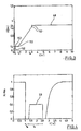
- FIG. 3 In the control modules 44 and 46 each have a voltage-time characteristic 48 is stored as in FIG. 3 is shown by way of example.
- the voltage time characteristic off FIG. 3 is defined by freely selectable support points 52, which in the present example are each connected to one another via lines.
- the voltage time characteristic in FIG. 3 describes a so-called voltage funnel, wherein the requirements of the network operator state that as long as the mains voltage is greater than the predetermined by the voltage-time characteristic 48 voltage value, a grid separation of the wind turbine must not occur. That is, in the double-fed asynchronous generator, the switch 50 is off FIG. 1 must remain closed.
- the predetermined by the voltage-time characteristic 48 voltage chute is characterized in that the wind turbine in a first short time interval until t 1 must also remain in the grid despite a very substantial voltage dip.
- the wind power plant may only disconnect from the grid when the grid voltage is below the voltage value U 2 . If the grid voltage does not increase at least linearly up to a voltage value of U 3 in a time interval t 2 to t 3 , the wind turbine may be disconnected from the grid. For a subsequent longer range, the wind turbine must be operated on the grid when the voltage value of U 4 is exceeded.
- interpolation points 52 indicated by crosses make it possible to define the voltage-time characteristic generally for the control.
- the voltage values in the interval t 1 to t 2 can be set to a value predetermined by the feed-in guidelines.
- control of the control modules 44 and 46 is carried out such that the setpoint specifications M * and I B * done so that the wind turbine does not disconnect from the grid and meet the detailed requirements of the network operators.
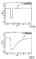
- FIG. 4 shows by way of example the course of the first reference variable function as a torque function 53 from the control module 44.
- a first time interval t B - begins at the beginning of the network error - the setpoint specification for the torque is set to zero.
- a desired value is set for the moment of approximately 40% of the rated torque.
- a torque reference value with the value zero is again applied to the generator-side converter 18.
- the setpoint for the generator-side converter 18 is increased approximately e-function-shaped again to the nominal value for the torque.
- torque function is dependent on the FRT requirements as given by the Voltage time characteristic in FIG. 3 are shown. To the torque function of FIG. 4 better to be able to consider in the control module, this is divided into two basic functions.
- FIG. 5 shows a first basic function that describes the course of the torque 55 after the occurrence of the error case.
- FIG. 6 shows the course of the second basic function as a torque function after the occurrence of the error, approximately after 1.7 seconds referred to the occurrence of the error, sets a parabolic rise of the torque setpoint on the rated power.
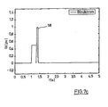
- FIGS. 7a to c show the overall behavior of the wind turbine in case of an error.
- the torque 56 of the wind turbine is reduced to zero immediately after the occurrence of the error case and is restarted after about 0.3 seconds.
- the torque of the wind turbine is again reduced to zero to be raised again after a defined period of time to the rated torque.
- the feed of the reactive current according to Fig. 7c starts directly with the error case.
- an increased reactive current 58 is fed in for compensation, which is reduced again when the fault has ended.
Landscapes
- Engineering & Computer Science (AREA)
- Power Engineering (AREA)
- Control Of Eletrric Generators (AREA)
- Wind Motors (AREA)
Priority Applications (1)
| Application Number | Priority Date | Filing Date | Title |
|---|---|---|---|
| PL09726921T PL2263306T3 (pl) | 2008-04-02 | 2009-04-02 | Sposób eksploatacji elektrowni wiatrowej z maszyną asynchroniczną z podwójnym zasilaniem oraz elektrownia wiatrowa z maszyną asynchroniczną z podwójnym zasilaniem |
Applications Claiming Priority (2)
| Application Number | Priority Date | Filing Date | Title |
|---|---|---|---|
| DE102008017715A DE102008017715A1 (de) | 2008-04-02 | 2008-04-02 | Verfahren zum Betreiben einer Windenergieanlage mit einer doppelt gespeisten Asynchronmaschine sowie Windenergieanlage mit einer doppelt gespeisten Asynchronmaschine |
| PCT/EP2009/002411 WO2009121596A2 (de) | 2008-04-02 | 2009-04-02 | Verfahren zum betreiben einer windenergieanlage mit einer doppelt gespeisten asynchronmaschine sowie windenergieanlage mit einer doppelt gespeisten asynchronmaschine |
Publications (2)
| Publication Number | Publication Date |
|---|---|
| EP2263306A2 EP2263306A2 (de) | 2010-12-22 |
| EP2263306B1 true EP2263306B1 (de) | 2012-01-04 |
Family
ID=41060423
Family Applications (1)
| Application Number | Title | Priority Date | Filing Date |
|---|---|---|---|
| EP09726921A Active EP2263306B1 (de) | 2008-04-02 | 2009-04-02 | Verfahren zum betreiben einer windenergieanlage mit einer doppelt gespeisten asynchronmaschine sowie windenergieanlage mit einer doppelt gespeisten asynchronmaschine |
Country Status (14)
| Country | Link |
|---|---|
| US (2) | US7948102B2 (pl) |
| EP (1) | EP2263306B1 (pl) |
| JP (1) | JP2011517264A (pl) |
| CN (1) | CN102027671B (pl) |
| AT (1) | ATE540467T1 (pl) |
| AU (1) | AU2009231231A1 (pl) |
| BR (1) | BRPI0910436A2 (pl) |
| CA (1) | CA2719302A1 (pl) |
| DE (1) | DE102008017715A1 (pl) |
| ES (1) | ES2379981T3 (pl) |
| NO (1) | NO20101507L (pl) |
| PL (1) | PL2263306T3 (pl) |
| RU (1) | RU2010143316A (pl) |
| WO (1) | WO2009121596A2 (pl) |
Families Citing this family (30)
| Publication number | Priority date | Publication date | Assignee | Title |
|---|---|---|---|---|
| USRE43698E1 (en) * | 2003-05-02 | 2012-10-02 | Schneider Electric USA, Inc. | Control system for doubly fed induction generator |
| US7816801B2 (en) * | 2006-03-16 | 2010-10-19 | International Components Corporation, Inc. | Speed sensing circuit for a wind turbine generator |
| DE102007060958A1 (de) * | 2007-12-14 | 2009-06-25 | Repower Systems Ag | Steuereinrichtung für Windenergieanlagen mit Netzausfallerkennung |
| DE102008017715A1 (de) * | 2008-04-02 | 2009-10-15 | Nordex Energy Gmbh | Verfahren zum Betreiben einer Windenergieanlage mit einer doppelt gespeisten Asynchronmaschine sowie Windenergieanlage mit einer doppelt gespeisten Asynchronmaschine |
| CN102318157B (zh) * | 2008-12-12 | 2014-07-23 | 维斯塔斯风力系统集团公司 | 控制方法和装置 |
| US8093739B2 (en) * | 2009-01-09 | 2012-01-10 | General Electric Company | System and method for fixed frequency power generation |
| US8018083B2 (en) * | 2010-08-05 | 2011-09-13 | General Electric Company | HVDC connection of wind turbine |
| US8093741B2 (en) * | 2010-10-29 | 2012-01-10 | General Electric Company | Method and system for providing increased turbine output for doubly fed induction generator |
| DK2463979T3 (da) * | 2010-12-08 | 2022-07-04 | Siemens Ag | Fremgangsmåde til gennemkørsel af fejltilstande (fault-ride-through, FTR), konverter og effektproducerende enhed til en vindmølle |
| US8121739B2 (en) * | 2010-12-29 | 2012-02-21 | Vestas Wind Systems A/S | Reactive power management for wind power plant internal grid |
| US9455633B2 (en) * | 2012-01-05 | 2016-09-27 | Ingeteam Power Technology, S.A. | Method and apparatus for controlling a frequency converter |
| CN104396113B (zh) * | 2012-06-12 | 2017-02-22 | 维斯塔斯风力系统集团公司 | 低压电网故障时的风力发电厂及其控制方法 |
| DE102013207255A1 (de) | 2013-04-22 | 2014-10-23 | Wobben Properties Gmbh | Verfahren zum Einspeisen elektrischer Leistung in ein elektrisches Versorgungsnetz |
| US9450409B2 (en) * | 2013-06-20 | 2016-09-20 | Abb Research Ltd. | Converter station power set point analysis system and method |
| US9425726B2 (en) * | 2013-06-25 | 2016-08-23 | Masdar Institute Of Science And Technology | Fault-tolerant wind energy conversion system |
| WO2015058769A1 (en) * | 2013-10-21 | 2015-04-30 | Vestas Wind Systems A/S | A method for controlling a wind power plant and a wind power plant |
| WO2015078474A1 (en) | 2013-11-28 | 2015-06-04 | Vestas Wind Systems A/S | A power plant controller for generating a power reference to wind turbine generators |
| JP6165644B2 (ja) * | 2014-01-24 | 2017-07-19 | 三菱重工業株式会社 | ウィンドファームおよびその運転方法 |
| CN103904971A (zh) * | 2014-04-15 | 2014-07-02 | 上海电机学院 | 基于双馈异步电机的故障控制装置及其方法 |
| CN103986403B (zh) * | 2014-05-30 | 2017-11-07 | 台达电子企业管理(上海)有限公司 | 变频调速系统及方法 |
| EP2955808B1 (de) * | 2014-06-13 | 2018-08-08 | Nordex Energy GmbH | Verfahren zur Regelung einer Windenergieanlage während eines asymmetrischen Netzfehlers |
| US10447040B2 (en) | 2014-10-15 | 2019-10-15 | Cummins Power Generation Ip, Inc. | Programmable inverter for controllable grid response |
| JP6923296B2 (ja) * | 2016-07-05 | 2021-08-18 | 株式会社日立製作所 | 風力発電設備とその運転方法およびウィンドファーム |
| DE102017108637A1 (de) | 2017-04-24 | 2018-10-25 | Wobben Properties Gmbh | Verfahren zum Erfassen einer Inselnetzbildung |
| DK3444939T3 (da) * | 2017-08-18 | 2021-03-08 | Nordex Energy Se & Co Kg | Fremgangsmåde til styring af et vindenergianlæg |
| EP3506449B1 (en) * | 2017-12-29 | 2025-09-17 | Nordex Energy Spain, S.A. | Method for operating electrical machines |
| EP3514910A1 (de) * | 2018-01-19 | 2019-07-24 | Nordex Energy GmbH | Verfahren zum betrieb einer windenergieanlage |
| CN110080944B (zh) * | 2018-01-26 | 2021-09-24 | 通用电气公司 | 风力发电系统及其控制方法 |
| DE102018102224A1 (de) * | 2018-02-01 | 2019-08-01 | Wobben Properties Gmbh | Verfahren zum Einspeisen elektrischer Leistung in ein elektrisches Versorgungsnetz |
| CN114172431B (zh) * | 2021-12-13 | 2023-06-27 | 国网福建省电力有限公司 | 一种双馈风机故障电流控制参数辨识方法 |
Family Cites Families (28)
| Publication number | Priority date | Publication date | Assignee | Title |
|---|---|---|---|---|
| US5083039B1 (en) * | 1991-02-01 | 1999-11-16 | Zond Energy Systems Inc | Variable speed wind turbine |
| JP3348944B2 (ja) * | 1993-12-27 | 2002-11-20 | 株式会社東芝 | 巻線形誘導機の制御装置 |
| US5619077A (en) * | 1994-03-18 | 1997-04-08 | Holophane Lighting, Inc. | System and method for providing alternate AC voltage |
| US5798631A (en) * | 1995-10-02 | 1998-08-25 | The State Of Oregon Acting By And Through The State Board Of Higher Education On Behalf Of Oregon State University | Performance optimization controller and control method for doubly-fed machines |
| US6137187A (en) * | 1997-08-08 | 2000-10-24 | Zond Energy Systems, Inc. | Variable speed wind turbine generator |
| US6600240B2 (en) * | 1997-08-08 | 2003-07-29 | General Electric Company | Variable speed wind turbine generator |
| AU2001274396A1 (en) * | 2000-05-23 | 2001-12-03 | Vestas Wind Systems A/S | Variable speed wind turbine having a matrix converter |
| JP2002010691A (ja) * | 2000-06-16 | 2002-01-11 | Mitsubishi Heavy Ind Ltd | 風力発電装置 |
| DE10140783A1 (de) * | 2001-08-21 | 2003-04-03 | Inst Solare Energieversorgungstechnik Iset | Vorrichtung zum gleichberechtigten Parallelbetrieb von ein- oder dreiphasigen Spannungsquellen |
| EP1470633A1 (de) * | 2002-01-29 | 2004-10-27 | Vestas Wind System A/S | Schaltungsanordnung zum einsatz bei einer windenergieanlage |
| US7015595B2 (en) * | 2002-02-11 | 2006-03-21 | Vestas Wind Systems A/S | Variable speed wind turbine having a passive grid side rectifier with scalar power control and dependent pitch control |
| DE10232423A1 (de) * | 2002-07-17 | 2004-01-29 | Ge Wind Energy Gmbh | Verfahren zum Betreiben einer Windenergieanlage und Windenergieanlage zum Ausführen derartiger Verfahren |
| US6879053B1 (en) * | 2002-10-22 | 2005-04-12 | Youtility, Inc. | Transformerless, load adaptive speed controller |
| US6921985B2 (en) | 2003-01-24 | 2005-07-26 | General Electric Company | Low voltage ride through for wind turbine generators |
| DE60329231D1 (de) * | 2003-02-07 | 2009-10-22 | Vestas Wind Sys As | Steuerverfahren für einen an ein hochspannungsnetz angeschlossenen windturbinengenerator während eines netzdefekts und vorrichtung zur implementierung dieses verfahrens |
| USRE43698E1 (en) * | 2003-05-02 | 2012-10-02 | Schneider Electric USA, Inc. | Control system for doubly fed induction generator |
| PT1499009E (pt) * | 2003-07-15 | 2008-01-14 | Gamesa Innovation & Tech Sl | Controlo e protecção de um sistema gerador de indução de dupla alimentação |
| BRPI0318500B1 (pt) | 2003-09-16 | 2016-10-18 | Gen Electric | método para operar um conversor de frequência de um gerador |
| JP4239088B2 (ja) * | 2003-12-19 | 2009-03-18 | 富士電機システムズ株式会社 | 風力発電設備 |
| JP4269941B2 (ja) * | 2004-01-08 | 2009-05-27 | 株式会社日立製作所 | 風力発電装置およびその制御方法 |
| JP4155196B2 (ja) * | 2004-01-13 | 2008-09-24 | 株式会社日立製作所 | 回転電機制御装置および発電システム |
| US7514907B2 (en) * | 2005-05-24 | 2009-04-07 | Satcon Technology Corporation | Device, system, and method for providing a low-voltage fault ride-through for a wind generator farm |
| JP4561518B2 (ja) * | 2005-07-27 | 2010-10-13 | 株式会社日立製作所 | 交流励磁同期発電機を用いた発電装置とその制御方法。 |
| US7423412B2 (en) | 2006-01-31 | 2008-09-09 | General Electric Company | Method, apparatus and computer program product for injecting current |
| CN101401294B (zh) * | 2006-03-17 | 2013-04-17 | 英捷电力技术有限公司 | 具有激励器设备和不连接至电网的功率变换器的变速风机 |
| US7425771B2 (en) * | 2006-03-17 | 2008-09-16 | Ingeteam S.A. | Variable speed wind turbine having an exciter machine and a power converter not connected to the grid |
| US7622815B2 (en) * | 2006-12-29 | 2009-11-24 | Ingeteam Energy, S.A. | Low voltage ride through system for a variable speed wind turbine having an exciter machine and a power converter not connected to the grid |
| DE102008017715A1 (de) * | 2008-04-02 | 2009-10-15 | Nordex Energy Gmbh | Verfahren zum Betreiben einer Windenergieanlage mit einer doppelt gespeisten Asynchronmaschine sowie Windenergieanlage mit einer doppelt gespeisten Asynchronmaschine |
-
2008
- 2008-04-02 DE DE102008017715A patent/DE102008017715A1/de not_active Withdrawn
- 2008-05-28 US US12/128,438 patent/US7948102B2/en active Active
-
2009
- 2009-04-02 JP JP2011502293A patent/JP2011517264A/ja active Pending
- 2009-04-02 ES ES09726921T patent/ES2379981T3/es active Active
- 2009-04-02 AT AT09726921T patent/ATE540467T1/de active
- 2009-04-02 BR BRPI0910436A patent/BRPI0910436A2/pt not_active IP Right Cessation
- 2009-04-02 AU AU2009231231A patent/AU2009231231A1/en not_active Abandoned
- 2009-04-02 PL PL09726921T patent/PL2263306T3/pl unknown
- 2009-04-02 RU RU2010143316/07A patent/RU2010143316A/ru not_active Application Discontinuation
- 2009-04-02 CN CN2009801177190A patent/CN102027671B/zh not_active Expired - Fee Related
- 2009-04-02 EP EP09726921A patent/EP2263306B1/de active Active
- 2009-04-02 WO PCT/EP2009/002411 patent/WO2009121596A2/de not_active Ceased
- 2009-04-02 US US12/936,089 patent/US8692399B2/en active Active
- 2009-04-02 CA CA2719302A patent/CA2719302A1/en not_active Abandoned
-
2010
- 2010-10-27 NO NO20101507A patent/NO20101507L/no not_active Application Discontinuation
Also Published As
| Publication number | Publication date |
|---|---|
| AU2009231231A1 (en) | 2009-10-08 |
| US7948102B2 (en) | 2011-05-24 |
| US20090250931A1 (en) | 2009-10-08 |
| WO2009121596A2 (de) | 2009-10-08 |
| WO2009121596A3 (de) | 2010-03-04 |
| RU2010143316A (ru) | 2012-05-10 |
| CN102027671B (zh) | 2013-08-07 |
| EP2263306A2 (de) | 2010-12-22 |
| US20110095532A1 (en) | 2011-04-28 |
| NO20101507L (no) | 2010-12-23 |
| PL2263306T3 (pl) | 2012-06-29 |
| JP2011517264A (ja) | 2011-05-26 |
| ES2379981T3 (es) | 2012-05-07 |
| DE102008017715A1 (de) | 2009-10-15 |
| US8692399B2 (en) | 2014-04-08 |
| BRPI0910436A2 (pt) | 2015-09-22 |
| CA2719302A1 (en) | 2009-10-08 |
| CN102027671A (zh) | 2011-04-20 |
| ATE540467T1 (de) | 2012-01-15 |
Similar Documents
| Publication | Publication Date | Title |
|---|---|---|
| EP2263306B1 (de) | Verfahren zum betreiben einer windenergieanlage mit einer doppelt gespeisten asynchronmaschine sowie windenergieanlage mit einer doppelt gespeisten asynchronmaschine | |
| EP2872777B1 (de) | Verfahren zum steuern eines elektrischen erzeugers | |
| EP2198497B1 (de) | Windenergieanlagen mit regelung für netzfehler und betriebsverfahren hierfür | |
| EP2873129B1 (de) | Verfahren und vorrichtung zum einspeisen elektrischer energie in ein elektrisches versorgungsnetz | |
| EP2614573B1 (de) | Verfahren zur stabilisierung eines elektrischen versorgungsnetzes | |
| EP2244373B1 (de) | Verfahren und elektrische Schaltung zum Testen eines an ein elektrisches Energieversorgungsnetz anschliessbaren Energieerzeugers oder Energieverbrauchers | |
| EP1752659B2 (de) | Verfahren zum Betrieb eines Windenergieanlagenparks | |
| AT508183B1 (de) | Verfahren zum betreiben einer windkraftanlage | |
| DE102018105483A1 (de) | Verfahren zum Betrieb einer Energieerzeugungsanlage und Wechselrichter für eine Energieerzeugungsanlage | |
| EP2457320A2 (de) | Verfahren zum betreiben einer windturbine sowie dazu geeignete windturbine | |
| EP3602722A1 (de) | Verfahren zum starten eines energieerzeugungsnetzes | |
| AT508182B1 (de) | Verfahren zum betreiben einer energiegewinnungsanlage, insbesondere windkraftanlage | |
| EP3780305A1 (de) | Wechselrichteranordnung für windenergieanlagen und photovoltaikanlagen | |
| EP1959136B1 (de) | Windpark umfassend Windenergieanlagen mit zueinander verschobenem Schwenkwinkel | |
| DE102005026062A1 (de) | Automatische Leistungs-Frequenz-Regelung und automatische Erzeugungsregelung mit selbstgeführten, pulsweitenmodulierten Wechselrichtern | |
| DE19719308A1 (de) | Verfahren zur Regelung der in ein Netz einzuspeisenden Ströme bei Windkraftanlagen sowie nach diesem Verfahren arbeitende Schaltung | |
| EP2442119A2 (de) | Verfahren und elektrische Schaltung zum Testen eines an ein elektrisches Energieversorgungsnetz anschließbaren Energieerzeugers oder Energieverbrauchers | |
| EP3311481B1 (de) | Verfahren zur regelung eines selbstgeführten umrichters, selbstgeführter umrichter sowie anordnung zur übertragung elektrischer leistung | |
| WO2018197468A1 (de) | Verfahren zum erfassen einer inselnetzbildung | |
| WO2022038222A1 (de) | Verfahren zum bereitstellen einer umrichterspannung einer umrichterbasierten erzeugungs- und/oder speicheranlage und steuervorrichtung zur durchführung des verfahrens | |
| EP3056916B1 (de) | Windenergieanlagen-prüfvorrichtung und verfahren zum prüfen einer windenergieanlage | |
| EP2521240A2 (de) | Elektrische Schaltung für einen Windpark | |
| DE102024102264B4 (de) | Betriebsverfahren für ein Teilnetz im Fall der Entkopplung vom Energieversorgungsnetz | |
| DE102009059284A1 (de) | Windkraftanlage | |
| WO2011085961A2 (de) | Verfahren und vorrichtung zum aufsynchronisieren eines generators in einem netz |
Legal Events
| Date | Code | Title | Description |
|---|---|---|---|
| PUAI | Public reference made under article 153(3) epc to a published international application that has entered the european phase |
Free format text: ORIGINAL CODE: 0009012 |
|
| 17P | Request for examination filed |
Effective date: 20101028 |
|
| AK | Designated contracting states |
Kind code of ref document: A2 Designated state(s): AT BE BG CH CY CZ DE DK EE ES FI FR GB GR HR HU IE IS IT LI LT LU LV MC MK MT NL NO PL PT RO SE SI SK TR |
|
| DAX | Request for extension of the european patent (deleted) | ||
| GRAP | Despatch of communication of intention to grant a patent |
Free format text: ORIGINAL CODE: EPIDOSNIGR1 |
|
| GRAS | Grant fee paid |
Free format text: ORIGINAL CODE: EPIDOSNIGR3 |
|
| GRAA | (expected) grant |
Free format text: ORIGINAL CODE: 0009210 |
|
| AK | Designated contracting states |
Kind code of ref document: B1 Designated state(s): AT BE BG CH CY CZ DE DK EE ES FI FR GB GR HR HU IE IS IT LI LT LU LV MC MK MT NL NO PL PT RO SE SI SK TR |
|
| REG | Reference to a national code |
Ref country code: GB Ref legal event code: FG4D Free format text: NOT ENGLISH |
|
| REG | Reference to a national code |
Ref country code: CH Ref legal event code: EP |
|
| REG | Reference to a national code |
Ref country code: AT Ref legal event code: REF Ref document number: 540467 Country of ref document: AT Kind code of ref document: T Effective date: 20120115 |
|
| REG | Reference to a national code |
Ref country code: IE Ref legal event code: FG4D |
|
| REG | Reference to a national code |
Ref country code: DE Ref legal event code: R096 Ref document number: 502009002383 Country of ref document: DE Effective date: 20120308 |
|
| REG | Reference to a national code |
Ref country code: SE Ref legal event code: TRGR |
|
| REG | Reference to a national code |
Ref country code: NL Ref legal event code: VDEP Effective date: 20120104 |
|
| REG | Reference to a national code |
Ref country code: ES Ref legal event code: FG2A Ref document number: 2379981 Country of ref document: ES Kind code of ref document: T3 Effective date: 20120507 |
|
| PG25 | Lapsed in a contracting state [announced via postgrant information from national office to epo] |
Ref country code: SI Free format text: LAPSE BECAUSE OF FAILURE TO SUBMIT A TRANSLATION OF THE DESCRIPTION OR TO PAY THE FEE WITHIN THE PRESCRIBED TIME-LIMIT Effective date: 20120104 |
|
| LTIE | Lt: invalidation of european patent or patent extension |
Effective date: 20120104 |
|
| REG | Reference to a national code |
Ref country code: PL Ref legal event code: T3 |
|
| PG25 | Lapsed in a contracting state [announced via postgrant information from national office to epo] |
Ref country code: NO Free format text: LAPSE BECAUSE OF FAILURE TO SUBMIT A TRANSLATION OF THE DESCRIPTION OR TO PAY THE FEE WITHIN THE PRESCRIBED TIME-LIMIT Effective date: 20120404 Ref country code: HR Free format text: LAPSE BECAUSE OF FAILURE TO SUBMIT A TRANSLATION OF THE DESCRIPTION OR TO PAY THE FEE WITHIN THE PRESCRIBED TIME-LIMIT Effective date: 20120104 Ref country code: IS Free format text: LAPSE BECAUSE OF FAILURE TO SUBMIT A TRANSLATION OF THE DESCRIPTION OR TO PAY THE FEE WITHIN THE PRESCRIBED TIME-LIMIT Effective date: 20120504 Ref country code: NL Free format text: LAPSE BECAUSE OF FAILURE TO SUBMIT A TRANSLATION OF THE DESCRIPTION OR TO PAY THE FEE WITHIN THE PRESCRIBED TIME-LIMIT Effective date: 20120104 Ref country code: BG Free format text: LAPSE BECAUSE OF FAILURE TO SUBMIT A TRANSLATION OF THE DESCRIPTION OR TO PAY THE FEE WITHIN THE PRESCRIBED TIME-LIMIT Effective date: 20120404 Ref country code: LT Free format text: LAPSE BECAUSE OF FAILURE TO SUBMIT A TRANSLATION OF THE DESCRIPTION OR TO PAY THE FEE WITHIN THE PRESCRIBED TIME-LIMIT Effective date: 20120104 |
|
| REG | Reference to a national code |
Ref country code: IE Ref legal event code: FD4D |
|
| PG25 | Lapsed in a contracting state [announced via postgrant information from national office to epo] |
Ref country code: FI Free format text: LAPSE BECAUSE OF FAILURE TO SUBMIT A TRANSLATION OF THE DESCRIPTION OR TO PAY THE FEE WITHIN THE PRESCRIBED TIME-LIMIT Effective date: 20120104 Ref country code: LV Free format text: LAPSE BECAUSE OF FAILURE TO SUBMIT A TRANSLATION OF THE DESCRIPTION OR TO PAY THE FEE WITHIN THE PRESCRIBED TIME-LIMIT Effective date: 20120104 Ref country code: GR Free format text: LAPSE BECAUSE OF FAILURE TO SUBMIT A TRANSLATION OF THE DESCRIPTION OR TO PAY THE FEE WITHIN THE PRESCRIBED TIME-LIMIT Effective date: 20120405 Ref country code: PT Free format text: LAPSE BECAUSE OF FAILURE TO SUBMIT A TRANSLATION OF THE DESCRIPTION OR TO PAY THE FEE WITHIN THE PRESCRIBED TIME-LIMIT Effective date: 20120504 |
|
| PG25 | Lapsed in a contracting state [announced via postgrant information from national office to epo] |
Ref country code: CY Free format text: LAPSE BECAUSE OF FAILURE TO SUBMIT A TRANSLATION OF THE DESCRIPTION OR TO PAY THE FEE WITHIN THE PRESCRIBED TIME-LIMIT Effective date: 20120104 |
|
| BERE | Be: lapsed |
Owner name: NORDEX ENERGY G.M.B.H. Effective date: 20120430 |
|
| PG25 | Lapsed in a contracting state [announced via postgrant information from national office to epo] |
Ref country code: EE Free format text: LAPSE BECAUSE OF FAILURE TO SUBMIT A TRANSLATION OF THE DESCRIPTION OR TO PAY THE FEE WITHIN THE PRESCRIBED TIME-LIMIT Effective date: 20120104 Ref country code: IE Free format text: LAPSE BECAUSE OF FAILURE TO SUBMIT A TRANSLATION OF THE DESCRIPTION OR TO PAY THE FEE WITHIN THE PRESCRIBED TIME-LIMIT Effective date: 20120104 Ref country code: RO Free format text: LAPSE BECAUSE OF FAILURE TO SUBMIT A TRANSLATION OF THE DESCRIPTION OR TO PAY THE FEE WITHIN THE PRESCRIBED TIME-LIMIT Effective date: 20120104 Ref country code: CZ Free format text: LAPSE BECAUSE OF FAILURE TO SUBMIT A TRANSLATION OF THE DESCRIPTION OR TO PAY THE FEE WITHIN THE PRESCRIBED TIME-LIMIT Effective date: 20120104 Ref country code: DK Free format text: LAPSE BECAUSE OF FAILURE TO SUBMIT A TRANSLATION OF THE DESCRIPTION OR TO PAY THE FEE WITHIN THE PRESCRIBED TIME-LIMIT Effective date: 20120104 |
|
| PLBE | No opposition filed within time limit |
Free format text: ORIGINAL CODE: 0009261 |
|
| STAA | Information on the status of an ep patent application or granted ep patent |
Free format text: STATUS: NO OPPOSITION FILED WITHIN TIME LIMIT |
|
| PG25 | Lapsed in a contracting state [announced via postgrant information from national office to epo] |
Ref country code: MC Free format text: LAPSE BECAUSE OF NON-PAYMENT OF DUE FEES Effective date: 20120430 Ref country code: IT Free format text: LAPSE BECAUSE OF FAILURE TO SUBMIT A TRANSLATION OF THE DESCRIPTION OR TO PAY THE FEE WITHIN THE PRESCRIBED TIME-LIMIT Effective date: 20120104 Ref country code: SK Free format text: LAPSE BECAUSE OF FAILURE TO SUBMIT A TRANSLATION OF THE DESCRIPTION OR TO PAY THE FEE WITHIN THE PRESCRIBED TIME-LIMIT Effective date: 20120104 |
|
| 26N | No opposition filed |
Effective date: 20121005 |
|
| PG25 | Lapsed in a contracting state [announced via postgrant information from national office to epo] |
Ref country code: BE Free format text: LAPSE BECAUSE OF NON-PAYMENT OF DUE FEES Effective date: 20120430 |
|
| REG | Reference to a national code |
Ref country code: DE Ref legal event code: R097 Ref document number: 502009002383 Country of ref document: DE Effective date: 20121005 |
|
| PG25 | Lapsed in a contracting state [announced via postgrant information from national office to epo] |
Ref country code: MK Free format text: LAPSE BECAUSE OF FAILURE TO SUBMIT A TRANSLATION OF THE DESCRIPTION OR TO PAY THE FEE WITHIN THE PRESCRIBED TIME-LIMIT Effective date: 20120104 |
|
| PG25 | Lapsed in a contracting state [announced via postgrant information from national office to epo] |
Ref country code: MT Free format text: LAPSE BECAUSE OF FAILURE TO SUBMIT A TRANSLATION OF THE DESCRIPTION OR TO PAY THE FEE WITHIN THE PRESCRIBED TIME-LIMIT Effective date: 20120104 |
|
| REG | Reference to a national code |
Ref country code: CH Ref legal event code: PL |
|
| PG25 | Lapsed in a contracting state [announced via postgrant information from national office to epo] |
Ref country code: CH Free format text: LAPSE BECAUSE OF NON-PAYMENT OF DUE FEES Effective date: 20130430 Ref country code: LI Free format text: LAPSE BECAUSE OF NON-PAYMENT OF DUE FEES Effective date: 20130430 |
|
| PG25 | Lapsed in a contracting state [announced via postgrant information from national office to epo] |
Ref country code: LU Free format text: LAPSE BECAUSE OF NON-PAYMENT OF DUE FEES Effective date: 20120402 |
|
| PG25 | Lapsed in a contracting state [announced via postgrant information from national office to epo] |
Ref country code: HU Free format text: LAPSE BECAUSE OF FAILURE TO SUBMIT A TRANSLATION OF THE DESCRIPTION OR TO PAY THE FEE WITHIN THE PRESCRIBED TIME-LIMIT Effective date: 20090402 |
|
| REG | Reference to a national code |
Ref country code: AT Ref legal event code: MM01 Ref document number: 540467 Country of ref document: AT Kind code of ref document: T Effective date: 20140402 |
|
| PG25 | Lapsed in a contracting state [announced via postgrant information from national office to epo] |
Ref country code: AT Free format text: LAPSE BECAUSE OF NON-PAYMENT OF DUE FEES Effective date: 20140402 |
|
| REG | Reference to a national code |
Ref country code: FR Ref legal event code: PLFP Year of fee payment: 8 |
|
| REG | Reference to a national code |
Ref country code: FR Ref legal event code: PLFP Year of fee payment: 9 |
|
| PGFP | Annual fee paid to national office [announced via postgrant information from national office to epo] |
Ref country code: PL Payment date: 20170306 Year of fee payment: 9 |
|
| PGFP | Annual fee paid to national office [announced via postgrant information from national office to epo] |
Ref country code: SE Payment date: 20170425 Year of fee payment: 9 |
|
| REG | Reference to a national code |
Ref country code: FR Ref legal event code: PLFP Year of fee payment: 10 |
|
| PGFP | Annual fee paid to national office [announced via postgrant information from national office to epo] |
Ref country code: TR Payment date: 20180322 Year of fee payment: 10 |
|
| PGFP | Annual fee paid to national office [announced via postgrant information from national office to epo] |
Ref country code: FR Payment date: 20180424 Year of fee payment: 10 |
|
| REG | Reference to a national code |
Ref country code: SE Ref legal event code: EUG |
|
| PG25 | Lapsed in a contracting state [announced via postgrant information from national office to epo] |
Ref country code: SE Free format text: LAPSE BECAUSE OF NON-PAYMENT OF DUE FEES Effective date: 20180403 |
|
| PG25 | Lapsed in a contracting state [announced via postgrant information from national office to epo] |
Ref country code: FR Free format text: LAPSE BECAUSE OF NON-PAYMENT OF DUE FEES Effective date: 20190430 |
|
| PG25 | Lapsed in a contracting state [announced via postgrant information from national office to epo] |
Ref country code: PL Free format text: LAPSE BECAUSE OF NON-PAYMENT OF DUE FEES Effective date: 20180402 |
|
| REG | Reference to a national code |
Ref country code: DE Ref legal event code: R082 Ref document number: 502009002383 Country of ref document: DE Representative=s name: HAUCK PATENTANWALTSPARTNERSCHAFT MBB, DE Ref country code: DE Ref legal event code: R081 Ref document number: 502009002383 Country of ref document: DE Owner name: NORDEX ENERGY SE & CO. KG, DE Free format text: FORMER OWNER: NORDEX ENERGY GMBH, 22848 NORDERSTEDT, DE |
|
| PG25 | Lapsed in a contracting state [announced via postgrant information from national office to epo] |
Ref country code: TR Free format text: LAPSE BECAUSE OF NON-PAYMENT OF DUE FEES Effective date: 20190402 |
|
| P01 | Opt-out of the competence of the unified patent court (upc) registered |
Effective date: 20230602 |
|
| PGFP | Annual fee paid to national office [announced via postgrant information from national office to epo] |
Ref country code: DE Payment date: 20250417 Year of fee payment: 17 |
|
| PGFP | Annual fee paid to national office [announced via postgrant information from national office to epo] |
Ref country code: ES Payment date: 20250519 Year of fee payment: 17 Ref country code: GB Payment date: 20250423 Year of fee payment: 17 |