EP2262060A1 - Système de mise à la terre pour un récipient - Google Patents
Système de mise à la terre pour un récipient Download PDFInfo
- Publication number
- EP2262060A1 EP2262060A1 EP09162400A EP09162400A EP2262060A1 EP 2262060 A1 EP2262060 A1 EP 2262060A1 EP 09162400 A EP09162400 A EP 09162400A EP 09162400 A EP09162400 A EP 09162400A EP 2262060 A1 EP2262060 A1 EP 2262060A1
- Authority
- EP
- European Patent Office
- Prior art keywords
- contacts
- grounding
- container
- contact
- ground
- Prior art date
- Legal status (The legal status is an assumption and is not a legal conclusion. Google has not performed a legal analysis and makes no representation as to the accuracy of the status listed.)
- Withdrawn
Links
Images

Classifications
-
- H—ELECTRICITY
- H01—ELECTRIC ELEMENTS
- H01R—ELECTRICALLY-CONDUCTIVE CONNECTIONS; STRUCTURAL ASSOCIATIONS OF A PLURALITY OF MUTUALLY-INSULATED ELECTRICAL CONNECTING ELEMENTS; COUPLING DEVICES; CURRENT COLLECTORS
- H01R4/00—Electrically-conductive connections between two or more conductive members in direct contact, i.e. touching one another; Means for effecting or maintaining such contact; Electrically-conductive connections having two or more spaced connecting locations for conductors and using contact members penetrating insulation
- H01R4/58—Electrically-conductive connections between two or more conductive members in direct contact, i.e. touching one another; Means for effecting or maintaining such contact; Electrically-conductive connections having two or more spaced connecting locations for conductors and using contact members penetrating insulation characterised by the form or material of the contacting members
- H01R4/66—Connections with the terrestrial mass, e.g. earth plate, earth pin
-
- H—ELECTRICITY
- H01—ELECTRIC ELEMENTS
- H01R—ELECTRICALLY-CONDUCTIVE CONNECTIONS; STRUCTURAL ASSOCIATIONS OF A PLURALITY OF MUTUALLY-INSULATED ELECTRICAL CONNECTING ELEMENTS; COUPLING DEVICES; CURRENT COLLECTORS
- H01R11/00—Individual connecting elements providing two or more spaced connecting locations for conductive members which are, or may be, thereby interconnected, e.g. end pieces for wires or cables supported by the wire or cable and having means for facilitating electrical connection to some other wire, terminal, or conductive member, blocks of binding posts
- H01R11/11—End pieces or tapping pieces for wires, supported by the wire and for facilitating electrical connection to some other wire, terminal or conductive member
- H01R11/30—End pieces held in contact by a magnet
-
- H—ELECTRICITY
- H01—ELECTRIC ELEMENTS
- H01R—ELECTRICALLY-CONDUCTIVE CONNECTIONS; STRUCTURAL ASSOCIATIONS OF A PLURALITY OF MUTUALLY-INSULATED ELECTRICAL CONNECTING ELEMENTS; COUPLING DEVICES; CURRENT COLLECTORS
- H01R13/00—Details of coupling devices of the kinds covered by groups H01R12/70 or H01R24/00 - H01R33/00
- H01R13/66—Structural association with built-in electrical component
- H01R13/665—Structural association with built-in electrical component with built-in electronic circuit
- H01R13/6683—Structural association with built-in electrical component with built-in electronic circuit with built-in sensor
-
- H—ELECTRICITY
- H01—ELECTRIC ELEMENTS
- H01R—ELECTRICALLY-CONDUCTIVE CONNECTIONS; STRUCTURAL ASSOCIATIONS OF A PLURALITY OF MUTUALLY-INSULATED ELECTRICAL CONNECTING ELEMENTS; COUPLING DEVICES; CURRENT COLLECTORS
- H01R13/00—Details of coupling devices of the kinds covered by groups H01R12/70 or H01R24/00 - H01R33/00
- H01R13/62—Means for facilitating engagement or disengagement of coupling parts or for holding them in engagement
- H01R13/6205—Two-part coupling devices held in engagement by a magnet
Definitions
- the present invention relates to a grounding system for grounding a container.
- the electrical grounding - thus establishing an electrical connection to a grounding potential - of a container, e.g. A barrel, canister or so-called big-bags, is necessary when filling or emptying the container with flammable or explosive materials such as liquids, gases or powders.
- An ungrounded container can be e.g. Electrostatically charged due to the charge separation caused by the material transfer. The potential difference caused by the charging can lead to an electrostatic discharge in the form of a spark, which could ignite the flammable or explosive materials.
- the grounding of the container and the transfer device, e.g. the filling nozzle prevents a potential difference builds up, since all parts are always kept at the same reference potential. By grounding the container thus an electrostatic charge is avoided as a source of ignition.
- grounding brackets are attached to the container, which conductively connect the container via a cable with a ground potential.
- a disadvantage of such type grounding that on the container a suitable projection must be present in order to attach the earthing clamp to it.
- a suitable projection In barrels, a suitable projection is usually in the form of a fold, which connects the lid with the lateral surface of the barrel.
- the attachment of a grounding clip can be disadvantageous here because the attached to the fold earthing clamp often protrudes upwards and thus the filling plant in the way.
- the use of earthing clamps is completely impossible if the containers to be grounded, such as barrels, are arranged side by side eg on a pallet. In this case, it is not possible to attach a grounding clip to the crease of a barrel as there is an adjacent cask in the way. Finally, it often happens that the fold is damaged by the clamp, for example, bent, which is particularly disadvantageous in immediately visible places.
- the present invention is therefore based on the object to eliminate the disadvantages of the prior art described above.
- the earth system according to the invention for grounding a container has a grounding contact with at least one magnet and at least two contacts, wherein the at least two contacts made of electrically conductive material, and wherein the at least two contacts are electrically insulated in the ground contact with each other.
- the grounding system according to the invention has a resistance measuring circuit which is suitable for measuring an electrical resistance value.
- the earthing system according to the invention comprises a first electrical conductor connecting a first of the at least two contacts to a ground, a second electrical conductor connecting a second of the at least two contacts to the resistance measuring circuit and a third electrical conductor connecting the resistance measuring circuit to the ground Grounding connects.
- the earth system according to the invention for grounding a container solves the above-described problem, since the grounding contact can be attached with the help of at least one magnet at any point of the container to be grounded.
- the grounding system according to the invention can now be grounded with the grounding system according to the invention and containers which are arranged on a pallet and to which a grounding clamp can not be attached or only with difficulty. Also, damage to a fold of the container can be avoided.
- the improvement of the electrical contact by the teeth or claws is due to the fact that they penetrate an oxide or corrosion layer, which is often found on the surfaces of metal containers, and contact the underlying conductive layer. Teeth or claws may also penetrate through a possibly existing coating, such as a lacquer layer of the container, thus establishing electrical contact between the underlying conductive layer and the contacts.
- the teeth, nubs or claws have a radius, ie their corners and / or edges are rounded, so that the container is not damaged when the contacts come into contact with the container. This is advantageous if the grounding contact is attached to a visible location of the container, where any damage to the container surface affects the visual impression of the container.
- the at least two contacts made of steel, stainless steel, brass, light metal or copper. These materials have a good specific conductivity and thus a low resistivity, whereby a potential potential difference between the container and the earth is minimized.
- the at least one magnet is a permanent magnet.
- a permanent magnet maintains its magnetization over a long period of time and ensures that the grounding contact always reliably adheres to the container.
- the grounding contact has two magnets and two contacts.
- the two magnets are each arranged in the two contacts. This arrangement allows a space-saving design of the grounding contact.
- each contact is assigned a spatial proximity magnet, whereby each of the two contacts is optimally pressed against the container, so that a good electrical connection between the contacts and the container is formed and the electrical contact resistance between the container and the contacts is as small as possible.
- the ground contact on a display which indicates whether the container is sufficiently grounded.
- the display gives the operator immediate feedback as to whether the container is sufficiently grounded, so that the filling or emptying of the container can be started.
- the at least two contacts made of magnetic material, so that the force of the at least one magnet is reinforced.
- a higher magnetic force advantageously results in a higher contact pressure and thus in an improved electrical contact between the contacts and the container.
- the earth contact according to the invention for use in a grounding system for grounding a container has at least one magnet and at least two contacts, wherein the at least two contacts made of electrically conductive material and wherein the at least two contacts in the ground contact with each other are electrically insulated.
- the grounding system has a resistance measuring circuit which is suitable for measuring an electrical resistance.
- the grounding system has a first electrical conductor for connecting the terminal of a first of the at least two contacts to a ground, a second electrical conductor for connecting the terminal of a second of the at least two contacts to the resistance measuring circuit and a third electrical conductor, which connects the resistance measuring circuit to ground.
- the method of grounding a package comprises the step of attaching a grounding contact to the package, wherein the grounding contact comprises at least one magnet and at least two contacts, wherein the at least two contacts are made of electrically conductive material, wherein the at least two contacts in the grounding contact wherein a first of the at least two contacts is connected via a first electrical conductor to a ground and a second of the at least two contacts via a second electrical conductor is connected to a resistance measuring circuit and the resistance measuring circuit via a third electrical conductor to the ground connected is.
- the method according to the invention for grounding a container has the step of measuring the electrical resistance value with the resistance measuring circuit.
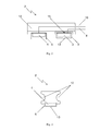
- Fig. 1 an embodiment of a grounding system 1 according to the invention for grounding a container shown.
- the grounding system 1 has a grounding contact 2. This one has in the in Fig. 1 Example shown a rectangular shape. However, any shapes are conceivable.
- the grounding contact has two magnets 3, 4 and two contacts 5, 6 in the embodiment shown. In principle, however, a different number of magnets or contacts is conceivable. For example, the grounding contact may have only one magnet, which is arranged between two contacts.
- the grounding contact is provided in the embodiment shown with a handle 12, which ensures easy handling of the grounding contact.
- the magnets 3, 4 have a rectangular cross-section in the embodiment shown. Conceivable, however, are other cross sections such as round.
- the magnets may be permanent magnets based on, for example, iron, cobalt, nickel or corresponding alloys thereof.
- the magnets but can also be designed as electromagnets, for example in the form of coils.
- the operating personnel can, for example, by means of a switch, the current flow through the coils turn on when the grounding contact is attached to a container. Accordingly, by means of the switch, the current flow through the coils can be switched off when the grounding contact is to be detached from the container.
- the realization of the magnets as electromagnets is useful when a high holding power is desired without the strong magnetic force hindering or unnecessarily complicating the attachment or removal of the grounding contact.
- the function of the magnets 3, 4 is to press the ground contact 2 to the surface of the container, ie to generate a force in the direction of the container surface. By this force, the grounding contact 2 is fixed to the container and made an electrical connection between the contacts 5, 6 and the container. Due to the force of the magnets, the earthing contact adheres independently to the container.
- the contacts are in the in Fig. 1 shown embodiment designed as sheets with a rectangular shape. However, other shapes are also conceivable.
- one magnet is arranged in each of the contacts, ie magnet 3 is arranged in contact 5 and magnet 4 is arranged in contact 6.
- each magnet is completely surrounded by a contact.
- the person skilled in the art knows that the magnets can also be arranged outside the contacts. For example, a single magnet can be placed between the two contacts to achieve the desired adhesion of the ground contact to a container.
- the contacts 5, 6 may be made of steel, stainless steel, brass, light metal, copper or other electrically conductive material. The contacts 5, 6 are arranged so that they do not touch and therefore there is no electrical connection between them in the ground contact.
- the exemplary contacts further include claws 13. When attaching the grounding contact to a container, the claws 13 come in contact with the
- the electrical contact 5 is connected to a ground 9 via a first electrical conductor 8.
- a second electrical conductor 10 connects the electrical contact 6 to the ohmmeter 7, and a third electrical conductor 11 connects the ohmmeter 7 to the ground 9.
- the electrical conductors 8, 10, 11 may be copper cables. As shown in the embodiment, the electrical conductors may be routed through the grounding contact and exit at one side of the grounding contact. It is also conceivable, however, another leadership of the ladder.
- the resistance measuring device 7 can measure the electrical resistance value of this current loop.
- Fig. 1 also shown a threshold circuit 14 which is connected to the ohmmeter 7.
- the threshold circuit compares the electrical resistance value of the current loop measured by the resistance measuring circuit 7 with a preset threshold value. Depending on this comparison, threshold circuit 14 may output a signal. If the resistance value measured by the resistance measuring circuit 7 is small, this is an indication that the contact resistance between the container and the contact 5, which is connected to the ground 9, is small. This in turn means that a potential potential difference between the container and ground 9 can be well balanced. If, on the other hand, the measured resistance value is large, this is an indication of a poor earth, which in turn can result in a large potential difference between the container and ground 9. However, the potential difference should be as small as possible to prevent electrostatic discharge and to prevent the generation of a spark.
- the reason for a large contact resistance between the container and the contact 5 may be, for example, that the grounding contact is not properly attached to the container, ie the two contacts 5, 6 do not sufficiently contact the container.
- Reason for this may be, for example, that the container is coated with a lacquer layer, which prevents a good electrical connection between the container and the contacts 5, 6. Therefore, for example, when the measured resistance value of the current loop exceeds the preset threshold value, an audible and / or visual signal can be output, since such exceeding may result in improper grounding of the container and thus an increased risk of ignition or explosion.
- the threshold circuit 14 can also interrupt a transfer process, ie filling or emptying of the container, in order to reduce the risk of ignition or explosion.
- the ground contact 2 has two identical U-shaped contacts 5 and 6.
- the contacts may be bent in this embodiment, for example made of sheet metal.
- the U-shaped contacts have a tooth 13 at each end of the legs of the U.
- the two contacts 5, 6 each have a magnet 3, 4 is attached. These can be glued, for example.
- the two contacts 5, 6 made of magnetic material, so that the magnetic field lines of the magnets 3, 4 are compressed in the two contacts 5, 6 and exit at the ends of the U-shaped contacts 5, 6, so that a higher contact pressure of the magnets 3, 4 results.
- the two contacts 5, 6 are in the in Fig. 2 shown preferred embodiment rotated by 90 ° to each other in the rest of the grounding contact arranged.
- the contact 6 is firmly connected to the rest of the ground contact, while the contact 5 is movably connected to the rest of the grounding contact.
- the contact 5 is connected to a spring 15 with the remainder of the grounding contact.
- the movable attachment of at least one of the contacts compensates for round or irregular container surfaces and thus improves the electrical contact.
- the grip of the ground contact 2 is in the form of round recesses 12 in the ground contact, thereby making the entire ground contact even more compact.
Landscapes
- Engineering & Computer Science (AREA)
- Microelectronics & Electronic Packaging (AREA)
- Measurement Of Resistance Or Impedance (AREA)
Priority Applications (1)
| Application Number | Priority Date | Filing Date | Title |
|---|---|---|---|
| EP09162400A EP2262060A1 (fr) | 2009-06-10 | 2009-06-10 | Système de mise à la terre pour un récipient |
Applications Claiming Priority (1)
| Application Number | Priority Date | Filing Date | Title |
|---|---|---|---|
| EP09162400A EP2262060A1 (fr) | 2009-06-10 | 2009-06-10 | Système de mise à la terre pour un récipient |
Publications (1)
| Publication Number | Publication Date |
|---|---|
| EP2262060A1 true EP2262060A1 (fr) | 2010-12-15 |
Family
ID=41259690
Family Applications (1)
| Application Number | Title | Priority Date | Filing Date |
|---|---|---|---|
| EP09162400A Withdrawn EP2262060A1 (fr) | 2009-06-10 | 2009-06-10 | Système de mise à la terre pour un récipient |
Country Status (1)
| Country | Link |
|---|---|
| EP (1) | EP2262060A1 (fr) |
Cited By (2)
| Publication number | Priority date | Publication date | Assignee | Title |
|---|---|---|---|---|
| CN103210316A (zh) * | 2011-01-17 | 2013-07-17 | 日东电工株式会社 | 接地装置 |
| CN109273876A (zh) * | 2018-10-24 | 2019-01-25 | 程海明 | 一种新型电力系统灭弧接地装置 |
Citations (9)
| Publication number | Priority date | Publication date | Assignee | Title |
|---|---|---|---|---|
| US3518607A (en) * | 1968-04-12 | 1970-06-30 | Richard F Reel | Safety ground device |
| EP0238017A2 (fr) * | 1986-03-21 | 1987-09-23 | BARTEL, Bernhard | Dispositif électrique avec au moins un récepteur électrique disposé amovible sur une surface |
| US5004425A (en) * | 1989-10-10 | 1991-04-02 | Jes, L.P. | Magnetic snap assembly for connecting grounding cord to electrically conductive body band |
| DE4011198A1 (de) * | 1990-04-04 | 1991-10-10 | Peter Graue | Vorrichtung zur elektrischen versorgung von elektrischen verbrauchern |
| US5290191A (en) * | 1991-04-29 | 1994-03-01 | Foreman Kevin G | Interface conditioning insert wafer |
| WO2001022533A1 (fr) * | 1999-09-23 | 2001-03-29 | Factor Tools International As | Borne de terre |
| JP2001289890A (ja) * | 2000-04-04 | 2001-10-19 | Dai Nippon Construction | 地盤の比抵抗測定装置 |
| DE202004008334U1 (de) * | 2004-05-25 | 2004-09-02 | Geb, Nikolaus | BGVAZ-Steckdosenleiste |
| DE102007010193A1 (de) * | 2007-02-18 | 2008-08-21 | Hidde, Axel R., Dr. | Elektrische Zustandsanzeige bei maritimen Schaltapparaten |
-
2009
- 2009-06-10 EP EP09162400A patent/EP2262060A1/fr not_active Withdrawn
Patent Citations (9)
| Publication number | Priority date | Publication date | Assignee | Title |
|---|---|---|---|---|
| US3518607A (en) * | 1968-04-12 | 1970-06-30 | Richard F Reel | Safety ground device |
| EP0238017A2 (fr) * | 1986-03-21 | 1987-09-23 | BARTEL, Bernhard | Dispositif électrique avec au moins un récepteur électrique disposé amovible sur une surface |
| US5004425A (en) * | 1989-10-10 | 1991-04-02 | Jes, L.P. | Magnetic snap assembly for connecting grounding cord to electrically conductive body band |
| DE4011198A1 (de) * | 1990-04-04 | 1991-10-10 | Peter Graue | Vorrichtung zur elektrischen versorgung von elektrischen verbrauchern |
| US5290191A (en) * | 1991-04-29 | 1994-03-01 | Foreman Kevin G | Interface conditioning insert wafer |
| WO2001022533A1 (fr) * | 1999-09-23 | 2001-03-29 | Factor Tools International As | Borne de terre |
| JP2001289890A (ja) * | 2000-04-04 | 2001-10-19 | Dai Nippon Construction | 地盤の比抵抗測定装置 |
| DE202004008334U1 (de) * | 2004-05-25 | 2004-09-02 | Geb, Nikolaus | BGVAZ-Steckdosenleiste |
| DE102007010193A1 (de) * | 2007-02-18 | 2008-08-21 | Hidde, Axel R., Dr. | Elektrische Zustandsanzeige bei maritimen Schaltapparaten |
Cited By (4)
| Publication number | Priority date | Publication date | Assignee | Title |
|---|---|---|---|---|
| CN103210316A (zh) * | 2011-01-17 | 2013-07-17 | 日东电工株式会社 | 接地装置 |
| EP2669692A1 (fr) * | 2011-01-17 | 2013-12-04 | Nitto Denko Corporation | Dispositif de mise à la terre |
| EP2669692A4 (fr) * | 2011-01-17 | 2014-07-30 | Nitto Denko Corp | Dispositif de mise à la terre |
| CN109273876A (zh) * | 2018-10-24 | 2019-01-25 | 程海明 | 一种新型电力系统灭弧接地装置 |
Similar Documents
| Publication | Publication Date | Title |
|---|---|---|
| WO2013004761A1 (fr) | Connecteur enfichable circulaire comportant un câble de raccordement blinde | |
| EP2262060A1 (fr) | Système de mise à la terre pour un récipient | |
| DE102018128783A1 (de) | Messeinrichtung für eine Ladeeinrichtung und Ladeeinrichtung | |
| EP2672278B1 (fr) | Instrument de mesure, notamment contrôleur de tension | |
| WO2014040830A1 (fr) | Transformateur de courant à tête interchangeable | |
| DE1230880B (de) | Elektrischer Schalter mit verschiebbarem Betaetigungsglied | |
| DE202020105266U1 (de) | Erdungsvorrichtung | |
| EP2237648A2 (fr) | Contact modifié pour la mise à terre | |
| EP3796474A2 (fr) | Dispositif de raccordement permettant de contacter électriquement un appareil électrique | |
| DE102018200621A1 (de) | Messanordnung mit einem Messwiderstand | |
| DE10125355A1 (de) | Verfahren und Vorrichtung zum Ermitteln des Füllstands in einem Kraftstoffvorratsbehälter | |
| DE102010060387A1 (de) | Elektrische Anschlusseinrichtung | |
| DE2259597C2 (de) | Vorrichtung zur Messung der Dicke von Fahrbahndecken | |
| EP0978319A1 (fr) | Dispositif de pulvérisation de poudre à charge externe et interne | |
| CH717091A2 (de) | Stromzange. | |
| DE2445350A1 (de) | Verfahren und vorrichtung zur feststellung von fehlern in magnetisierbaren gegenstaenden | |
| DE102011007954B4 (de) | Sammelschiene | |
| EP2866234B1 (fr) | Bobine de démagnétisation | |
| WO2004044597A2 (fr) | Dispositif et procede pour determiner l'absence d'application de contraintes sur des lignes electriques polyphasees | |
| EP3433871B1 (fr) | Dispositif de mesure d'un état d'un commutateur électrique, commutateur électrique et procédé de mesure d'un état d'un commutateur électrique | |
| DE102008010626A1 (de) | Kraftfahrzeug mit nichtleitendem Masseanschluss eines Gasgenerators | |
| DE102013218716A1 (de) | Prüfeinrichtung für elektrische Komponenten | |
| DE291498C (fr) | ||
| DE1552040C (de) | Tragbare magnetische Metallbearbeitungsvorrichtung | |
| DE102017212206A1 (de) | Verfahren zum Betrieb einer Sicherheitsvorrichtung |
Legal Events
| Date | Code | Title | Description |
|---|---|---|---|
| PUAI | Public reference made under article 153(3) epc to a published international application that has entered the european phase |
Free format text: ORIGINAL CODE: 0009012 |
|
| AK | Designated contracting states |
Kind code of ref document: A1 Designated state(s): AT BE BG CH CY CZ DE DK EE ES FI FR GB GR HR HU IE IS IT LI LT LU LV MC MK MT NL NO PL PT RO SE SI SK TR |
|
| STAA | Information on the status of an ep patent application or granted ep patent |
Free format text: STATUS: THE APPLICATION IS DEEMED TO BE WITHDRAWN |
|
| 18D | Application deemed to be withdrawn |
Effective date: 20110616 |