EP2261827B1 - Procédé, programme et appareil pour l'affichage d'un ensemble d'objets d'une base de données PLM - Google Patents
Procédé, programme et appareil pour l'affichage d'un ensemble d'objets d'une base de données PLM Download PDFInfo
- Publication number
- EP2261827B1 EP2261827B1 EP09290430.9A EP09290430A EP2261827B1 EP 2261827 B1 EP2261827 B1 EP 2261827B1 EP 09290430 A EP09290430 A EP 09290430A EP 2261827 B1 EP2261827 B1 EP 2261827B1
- Authority
- EP
- European Patent Office
- Prior art keywords
- objects
- assembly
- database
- identified
- product
- Prior art date
- Legal status (The legal status is an assumption and is not a legal conclusion. Google has not performed a legal analysis and makes no representation as to the accuracy of the status listed.)
- Active
Links
Images


Classifications
-
- G—PHYSICS
- G06—COMPUTING; CALCULATING OR COUNTING
- G06T—IMAGE DATA PROCESSING OR GENERATION, IN GENERAL
- G06T15/00—3D [Three Dimensional] image rendering
- G06T15/06—Ray-tracing
-
- G—PHYSICS
- G06—COMPUTING; CALCULATING OR COUNTING
- G06F—ELECTRIC DIGITAL DATA PROCESSING
- G06F30/00—Computer-aided design [CAD]
-
- G—PHYSICS
- G06—COMPUTING; CALCULATING OR COUNTING
- G06T—IMAGE DATA PROCESSING OR GENERATION, IN GENERAL
- G06T19/00—Manipulating 3D models or images for computer graphics
-
- G—PHYSICS
- G06—COMPUTING; CALCULATING OR COUNTING
- G06F—ELECTRIC DIGITAL DATA PROCESSING
- G06F2111/00—Details relating to CAD techniques
- G06F2111/02—CAD in a network environment, e.g. collaborative CAD or distributed simulation
-
- G—PHYSICS
- G06—COMPUTING; CALCULATING OR COUNTING
- G06T—IMAGE DATA PROCESSING OR GENERATION, IN GENERAL
- G06T2210/00—Indexing scheme for image generation or computer graphics
- G06T2210/12—Bounding box
-
- G—PHYSICS
- G06—COMPUTING; CALCULATING OR COUNTING
- G06T—IMAGE DATA PROCESSING OR GENERATION, IN GENERAL
- G06T2219/00—Indexing scheme for manipulating 3D models or images for computer graphics
- G06T2219/20—Indexing scheme for editing of 3D models
- G06T2219/2008—Assembling, disassembling
Definitions
- the invention relates to the field of computer-implemented processes, programs, and more specifically to product life cycle management solutions, which comprise databases of data representative of modeled objects.
- CAD computer-aided design
- NURBS non-uniform rational B-splines
- geometry and representation may be stored in a single CAD file or multiple ones.
- CAD systems include graphic tools for representing the modeled objects to the designers; these tools are dedicated to the display of complex objects - the typical size of a file representing an object in a CAD system being in the range of a Mega-byte for part, and an assembly may comprise thousands of parts.
- a CAD system manages models of objects, which are stored in electronic files.
- PLMIA product life cycle management
- Such PLM solutions comprise a relational database of products.
- a database is usually defined as a collection of data (typically data and relations between the data) organized for rapid search and retrieval. Databases are structured to facilitate storage, retrieval, modification, and deletion of data in conjunction with various data-processing operations. Databases generally consist of a file or set of files that can be broken down into records, each of which consists of one or more fields. Fields are the basic units of data storage. Users retrieve database information primarily through queries. Using keywords and sorting commands, users can search, rearrange, group, and select the field in many records to retrieve or create reports on particular aggregates of data according to the rules of the database management system being used.
- a basic need of a user is to visualize a complex product made of thousand objects/parts and this, possibly according to different views or different viewpoints (virtual camera).
- the user may notably modify the viewpoint while viewing the modeled product being displayed, e.g . a sales engineer may whish to show an overview of a product to his customers.
- the standard solution to this problem is to load in the client computer memory the whole model stored on the PLM database and corresponding to the assembly of said objects, including a three dimensional graphic representation of the model and all the information on said objects such as geometry, constraints..., but also hyperlinks to other objects.
- the critical problem is that the global amount of visualization data is too large to fit in the client computer memory or at least too large for enabling a rapid display.
- the rendering time of a view of said product may be cripplingly long.
- loading the whole model and/or selecting individual parts is not always necessary for a user, e.g . the sales engineer solely needs to show to his customers an overview of the product.
- the document WO 2006/105416 describes a method for determining a simplified representation of an assembly model comprising the steps of saving a plurality of display states and configuration settings of an assembly model in a design representation, translating said design representation into a simplified representation by use of a visibility solution, and storing said simplified representation and said design representation in an assembly document.
- Another solution consists in navigating in a PLM database without loading the whole model.
- a viewpoint on a view of objects to be rendered is identified.
- the view is rendered according to the identified viewpoint.
- a plurality of locations in the view are determined, which are for example obtained according to a grid.
- the database is queried and modeled objects are identified according to said locations.
- rays passing through the viewpoint and the locations are cast, and modeled objects intersecting the rays are identified.
- the modeled objects identified are incrementally displayed in the graphical user interface so as to render a three dimensional view of the modeled objects.
- the visual navigation thus lacks of fluidity and ergonomics, and is time consuming for the user. Moreover, even if a new selected viewpoint was previously selected, the whole process has still to be repeated. Indeed, resources of the client computer are limited, e.g . the memory of the client is cleared as a new view is displayed.
- the client computer of the user may be in communication through a product data management (PDM) system via a computer network such as a Local Area Network (LAN) or a Wide Area Network (WAN).
- PDM product data management
- LAN Local Area Network
- WAN Wide Area Network
- LAN Local Area Network
- WAN Wide Area Network
- Requests performed by the client computer pass over the network, and responses provided by the PDM system are also transported by the network.
- the repetition of the whole process involves a huge consumption of the resources of the PDM system, but also a large consumption of the network bandwidth.
- the network is congested, and others networks parameters such as latency, delay, jitter, packet dropping probability, queuing delay, bit error rate are degraded.
- the network is overwhelmed and its overall performances strongly decrease.
- the invention therefore provides a process for displaying an assembly of objects of a product lifecycle management database according to claim 1.
- the invention further proposes a computer program stored on a computer readable medium, for displaying an assembly of objects of a product lifecycle management database, comprising code means for causing a computer to take the steps of the process of the invention.
- the invention still concerns an apparatus for displaying an assembly of objects of a product lifecycle management database, the apparatus comprising means for implementing the steps of the process of the invention.
- the invention is directed to a process for displaying an assembly of objects of a product lifecycle management (PLM) database.
- PLM product lifecycle management
- An access to the PLM database is provided, and an assembly of objects in the PLM database is selected.
- the assembly of objects is a product, and objects of the assembly are three-dimensional (3D) modeled objects.
- a plurality of viewpoints is identified on the selected assembly.
- a viewpoint refers to a specific location from which a view of the assembly may be displayed.
- a set of objects of the selected assembly is retrieved from the database according the plurality of viewpoints identified.
- a model of the selected assembly is computed for all the retrieved objects of the set of objects, and a view of the computed model is displayed, any displayed view being computed locally starting from the objects of the retrieved set of objects.
- the computed model of the assembly of objects is a three-dimensional (3D) model displayed on a graphical user interface
- the set of objects of the selected assembly is retrieved according to the plurality of identified viewpoints.
- the process of the invention is not limited to a specific viewpoint, e.g . a viewpoint selected by the user.
- the proposed invention takes into account the plurality of viewpoints: the computed model of the selected assembly is representative of the plurality of viewpoints.
- the computed model is a single model representative of a multiplicity of viewpoints.
- the proposed invention is thus particularly advantageous as the set of objects required to compute the model is retrieved at one time by a client computer of a user, while the prior art involves querying the database each time a new viewpoint is selected. Therefore, the number of requests performed on the PLM database is drastically reduced, and hardware resources of the server hosting the database are preserved. Additionally, the proposed invention also preserves resources of the network: a single request is performed by the client computer so as to retrieve the set of objects instead of multiple requests, and thus, the consumption of network resources such as bandwidth is reduced. Moreover, a better visual navigation of the selected assembly is provided: once the computed model has been computed by the client computer, views of the assembly can be displayed starting from the computed model. As a result, the display of a view of the assembly of objects is faster, and the visual navigation is fluider and smoother.
- the exemplified graphical user interface (or GUI) 100 may be a typical CAD-like interface, having standard menu bars 110, 120, as well as bottom and side toolbars 140, 150.
- Such menu and toolbars contain a set of user-selectable icons, each icon being associated with one or more operations or functions, as known in the art.
- the software tools may be grouped into workbenches.
- Each workbench comprises a subset of software tools.
- one of the workbenches is an edition workbench, suitable for editing geometrical features of the modeled product 200.
- a designer may for example pre-select a part of the object 200 and then initiate an operation (e.g. change the dimension, color, etc.) or edit geometrical constraints by selecting an appropriate icon.
- typical CAD operations are the modeling of the punching or the folding of a 3D modeled object displayed on the screen.
- the GUI may for example display data 250 related to the displayed product 200.
- the data 250 displayed as a "feature tree", and their 3D representation 200 pertain to a brake assembly including brake caliper and disc.
- the GUI may further show various types of graphic tool 130, 400, for example for facilitating 3D orientation of the object, for triggering a simulation of an operation of an edited product or render various attributes of the displayed product 200.
- FIG. 12 illustrates a schematic view of an embodiment of a network architecture adapted for carrying out the invention.
- the client computers are in communication through the PDM system, allowing for the management of numerous documents, relations and data, possibly hierarchically interrelated.
- the PDM system may for example be located at a backbone of the network.
- Such a PDM system utilizes a database having data related to modeled objects, which are likely to be edited by a designer. A plurality of users may thus work in a collaborative way, on different objects (for example parts, products or assemblies of parts), as illustrated on FIG. 12 .
- GUI 100 and associated CAD/CAM/CAE application may be designed for allowing access to the PLM database, either on client computers request or as a background task.
- a user who wishes to access the database does not have to pass from a first CAD window to a PDM window (for example by minimizing the first window and maximizing the second window) and then go back to the CAD window.
- Such window switching operations frequently carried out by designers, are time consuming and particularly inappropriate in the field of CAD/CAM/CAE.
- the GUI 100 is run on one client computer of the network, having a display and memory. For instance, GUIs similar to that identified by reference numeral 100 displayed in FIG. 1 may be run on other client computers of the network. These computers may further benefit from similar local CAD/CAM/CAE applications and, more generally, a common environment.
- the process broadly decomposes as a build time (step S10) and a run time (steps S20 - S110).
- the build time is mainly dedicated to bounding volumes computation and, possibly, to the creation of an index of the objects.
- the step S10 provides to the next steps pre-computed bounding volumes stored on a database, typically a PLM database.
- a database typically a PLM database.
- bounding volume or bounding boxes, it is meant any mathematically simpler surface enclosing an object, for example for the purposes of culling or intersection tests.
- objects are three-dimensional modeled objects, and typical bounding volumes of the objects are for example cubes, cylinder boxes or spheres. Use is made of bounding boxes in the following.
- Bounding boxes of respective objects to be displayed are computed and subsequently stored in the PLM database. Such bounding boxes are stored together with a relation to their corresponding object. Geometric definitions of objects can be used to compute said boxes. The definitions used may either be the complete definitions or simplified definitions, such as the definitions of tessellated representations of said objects.
- one uses definitions of tessellated representations, which gives rise to faster computation times.
- a product as a hierarchy of objects, e.g. a tree
- it is for example first computed boxes pertaining to terminal nodes of the tree.
- Product structure definitions are then used to compute (step S10) the boxes of an assembly of objects, thanks to the definition of the structure and the terminal boxes already generated.
- subdivided boxes are computed and stored in the database, together with respective parent bounding boxes.
- Parent bounding boxes are in this case the parent nodes of an octree, that is, a tree data structure wherein each parent node has eight child nodes, which together partition the volume of space of the parent node.
- each node of the tree represents a cuboid volume, e.g. a subdivided bounding volume.
- Several subdivisions can be contemplated (parents, children, children's children, etc.), depending on the desired resolution.
- bounding box only one bounding box is preferably stored for multi-instantiated objects of the set of objects. That is, bounding boxes are computed for the references only. In this case, instances of a same reference are likely to be stored together with a position matrix (or a link thereto). Hence, in operation, a box may be equated on-the-fly to any of the multi-instantiated objects upon a simple Cartesian system change. Moreover, resources are saved on the database as less bounding boxes are stored on the database.
- the process further comprises a step S20 consisting in selecting a product, a precision, and a configuration.
- a product is comprised of an assembly of objects.
- the selection of the product may for instance be done thanks to the use of a tree, such as the one 250 of FIG. 1 . It is also possible for the user to select the product thanks to another type of user interface, for instance by inputting identification information for the product, by selecting the product in a list, or the like.
- the selection of the precision and the configuration of the displayed view of the model may be performed thanks to any kind of user interface such as a combo-box, an icon, a special command or a right click, or the like. Furthermore, the precision and/or the configuration may be selected by default.
- the precision reflects the degree of refinement with which the view of the model is displayed, that is, an accuracy of the view.
- the accuracy of the view involves exactness and quality of the view. For instance, a modem airplane may require up to 3 millions objects. Depending on the selected precision, a view of the airplane will show or not the rivets of the fuselage.
- the precision may be represented by a numerical scale, from 0 for a less accurate display to 9 for a very accurate display.
- the precision may contribute to reduce the resources required to perform the process of the invention.
- the precision allows determining the hardware resources required to display the view. Less accurate is the display, less resources are required to retrieve from the database the set of object, compute the model, and display a view of the model; conversely, more accurate is the display, more resources are required to retrieve the set of object, to compute the model, and to display a view of the model.
- the time required to display a view of the model depends on the selected precision; the less accurate is the display, quicker is the display of the view, and the more accurate is the display, slower is the display of the view.
- the selection of the precision makes it possible to display a view of the model even if the client computer has limited resources, e.g . a sales engineer may launch the display of the model view on a laptop computer which has fewer resources than a workstation.
- a sales engineer may launch the display of the model view on a laptop computer which has fewer resources than a workstation.
- the process of the proposed invention may be adapted to hardware constrains. Precision will be further detailed in the description.
- the configuration is an arrangement of the product or of objects of the product.
- the configurations could be for example commercial configurations, e.g . including different colors and material available for the product.
- a model of car may have hundred of configurations based on the combinations of elements such the car style (coupe, convertible,%), the type of transmission (manual, auto,%) , exterior and interior options (colors, wheel type, seat style, radio,).
- the selection of the configuration thus allows the user to show a product according to the whishes of the customer, that is, according to the whished configuration.
- a precomputed bounding box of the product is retrieved from the PLM database, e.g . a cube enclosing the selected product is retrieved.
- the server hosting the PLM database retrieves the bounding box and stores it in memory.
- steps S40 - S60 the process identifies a plurality of viewpoints on the selected assembly.
- these steps are performed by the server hosting the PLM database, e.g . the PDM system.
- the server hosting the PLM database e.g . the PDM system.
- step S40 faces of the precomputed bounding box of the selected product are identified. This step is performed as well known in the art.
- step S50 it is computed a number of rays or any geometrical equivalent for each identified face of the bounding box of the product according to the selected precision at step S20.
- the precision is proportional to a ratio between a number of rays passing through the identified face and the surface of the identified face.
- the number of rays computed for each face of the bounding box of the selected product is thus proportional to a multiplication between the surface of the identified face and the selected precision.
- the proportionality between the number of rays computed and the multiplication may be determined via a constant of proportionality.
- the constant of proportionality may be:
- a viewpoint is a specific location from which a view of the assembly of objects may be displayed.
- a viewpoint is representative of a location of a virtual camera in a scene wherein the assembly of objects is also located.
- the scene is a space in which spatial relationships between objects are described.
- the scene is comprised of at least one object, and the object(s) may be modeled object(s) or three-dimensional (3D) modeled object(s).
- 3D three-dimensional
- the identified viewpoints are located “outside” of the product.
- a viewpoint is located “outside” a product when the viewpoint is in contact or is not within anyone of objects of the product.
- the viewpoint is outside when it is beyond an enclosure or boundary formed by the product.
- the identification of the plurality of viewpoints may comprises identifying faces of a bounding volume of the assembly of objects and identifying at least a viewpoint for each identified face of the bounding volume.
- a viewpoint is located "outside” a product when the viewpoint is in contact or is not within the bounding box of the product (which encloses the bounding boxes of the objects of the product). Therefore, the viewpoint is located "outside” the product when it is situated in a place beyond an enclosure or boundary of the bounding box of the product.
- the model computed at step S100 will allow a visual navigation around the product, that is, the visualization of the model according to several successive viewpoints located outside the selected product.
- the number of identified viewpoints for each identified face of the bounding box is inferior or equal to the number of rays computed at step S50 so as to limit the number of identified viewpoints.
- the number of viewpoints for each identified face of the bounding box is determined based on an average number of rays that shall pass through each viewpoint.
- the average number of rays that shall pass through each viewpoint may be determined by default, or selected by the user.
- the selection of the average number of rays may for instance be done in a similar way as for the selection of the precision or configuration.
- step S70 rays or any geometrical equivalent passing through the identified viewpoints and faces of the precomputed bounding box of the selected product are computed or cast.
- a set of objects of the selected product is retrieved from the database according to the plurality of identified viewpoints. To this aim, it is identified one or more bounding boxes for each respective object of the product intersecting the computed ray.
- bounding boxes of the objects of the selected product are retrieved from the database and may be stored together, e.g . in memory of the server hosting the PLM database. Retrieval of the bounding boxes of the objects may be carried out thanks to the product structure and the relations between the objects thereon.
- FIG. 6 in relation with FIG. 5 , illustrates the retrieval of the bounding box of the selected product carried out at the step S30, and also the retrieval of the bounding boxes of the objects of the product.
- FIG. 5 depicts a product 50 which is composed of three objects: a parallelepiped 51 placed side by side with a cylinder 52, the parallelepiped 51 and the cylinder 52 being fit together by a stem 53.
- the stem 53 is shown with dotted lines as it is enclosed in the parallelepiped 51 and the cylinder 52.
- FIG. 6 illustrates four bounding boxes which are retrieved: a bounding box 60 pertaining to the product 50 and retrieved at the step S30, three bounding boxes 61, 62, 63 enclosed by the bounding box 60, respectively related to the parallelepiped 51, the cylinder 52 and the stem 53, and retrieved prior to identifying the bounding boxes intersecting the computed ray.
- a bounding box is a mathematically simpler surface enclosing an object and its coordinates in a Cartesian system are simple, thus facilitating the determination of an intersection. Therefore, computing intersections between bounding boxes and computed rays requires fewer resources; especially, memory of the PDM system is preserved.
- the algorithm may for example scan all bounding boxes in order to determine which boxes intersect said computed ray. This step is carried out in the coordinate system of the reference view.
- R-tree technique that is, a spatial access method, wherein space is split with hierarchically nested, possibly overlapping, boxes.
- R-tree technique a spatial access method, wherein space is split with hierarchically nested, possibly overlapping, boxes.
- the initial ray is recomputed in the coordinate system of said intersected child instance and a new scan is performed within child instances thereof, etc. until no more intersection is found.
- intersection research algorithm is thus recursive, that is, it is searched the last intersected child of an n th -order intersected parent box, and runs as follows:
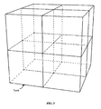
- the process works at a smaller subdivision level within the intersected bounding box. For example, one may consider the octrees, which are volumes dividing in eight a cubic box as shown in FIG. 3 .
- Octrees 300 are themselves for example further subdivided, as shown in FIG. 4 (represented in two dimension for the sake of clarity) except if an octree 310 does not contain any element of a model or is completely filled with an element of a model. Each octree 300 containing an element of the model is further subdivided.
- the octrees 300 are therefore scanned to detect any intersection with the computed ray, until the smallest undivided volume, known as a voxel 320 (which size may for instance depend on the definition input by the user). The process then stops and the object in the view that is inside (or close to) the identified voxel is selected.
- an object it is determined if the object is visible from the viewpoint or not. An object is visible when it is not completely hidden by another object. Then, the process recursively tests other bounding boxes according to the same steps (bounding boxes, octrees, voxels) to find and select the object that would be visible from the viewpoints. In order to optimize the process, if a bounding box does not intersect the computed ray (in the new coordinate system), then this bounding box is discarded. Similarly, if a bounding box is intersected by the ray but if, meanwhile, the object of the bounding box is not visible from at least one of the identified viewpoints, then said bounding box will be discarded.
- the bounding box of the product is a particular bounding box. Indeed, it does not necessarily comprise objects, but solely bounding boxes of the objects of the product. Thus, even if the bounding box of the product is intersected by the computed rays, any object may be selected. In order to optimize the process, the intersection research algorithm does not apply to the bounding box of the product, but solely applies to the bounding boxes enclosed by the bounding box of the product and their respective octrees and voxels.
- the bounding box of the product is mainly used to identify a volume in the scene wherein the selected product is located. This volume advantageously limits a space towards which computed rays have to be cast.
- the bounding box of the product is as smallest as possible, that is, its volume is the minimal bounding box which can enclose bounding boxes of the objects of the product.
- the identified object is stored.
- information related to the identification of the object e.g . the name of the object
- a file may form for instance an index which comprises the set of objects of the selected product retrieved from the database according to the identified viewpoints.
- the index is retrieved by the client computer.
- the computed rays may pass through identified faces with an angle of incidence substantially normal to the faces of the bounding box of the product.
- only one ray having an angle of incidence substantially normal to a face is computed for a given viewpoint. Indeed, for a given viewpoint, computing or casting a ray having the same angle of incidence than another one is useless since the second ray would intersect the same bounding boxes as the first ray.
- the angle of incidence is the angle between a ray incident on a face and a line perpendicular to the face at the point of incidence, as depicted on FIG. 7.
- FIG. 7 is a schematic view of a front view of a face 63 of the bounding box 60 of the FIG. 6 . It is depicted two rays 71 and 72 having an angle of incidence, respectively the angle noted ⁇ and the angle noted ⁇ .
- the angle of incidence of each one of the rays 71 and 72 is defined in comparison with a line 70 perpendicular to the surface at the point of incidence.
- the computed rays may pass through identified faces with an angle of incidence ranging from 0 degree to 45 degrees.
- the angles ⁇ and ⁇ may take values comprised between 0 and 45 degrees. It results that the identification of one or more bounding boxes of a respective object of the product intersecting computed rays is improved. Indeed, it provides the capability to identify bounding boxes that, otherwise, would not be identified, as depicted on FIG. 8 which is a schematic view of the front view of the face 64 of the bounding box 60 on FIG. 6 .
- Each point drawn on the face 64 represents a point of incidence of a computed ray passing through the face 64 with an angle of incidence substantially normal. Now, one focuses on the point of incidence noted 75.
- the computed ray normal to the point of incidence 75 does not intersect any of the three bounding boxes 61, 62, and 63 enclosed by the bounding box 60.
- Two computed rays 76 and 77 passing through the point of incidence 75 are represented. Thanks to its angle of incidence, the computed rays 76 (respectively 77) intersects the bounding box 61 (respectively 62).
- the bounding box 63 is not retrieved as the related object 53 is completely hidden by the objects 51 and 52.
- the object 53 is not visible from any of the identified viewpoints, and thus the object 53 is not an object of the set of objects retrieved from the database.
- retrieving from the database the set of objects is carried out according to security context of the user.
- User security contexts are related to access control, that is, the ability to permit or deny the use of a particular resource by a particular user.
- a user may be allowed or not to read, and/or write, and/or execute ( e.g . display) an object.
- a modeled object may be locked by the designer who has the responsibility of the modeled object, which means that other users are not allowed to modify the modeled object until the designer unlock the modeled object.
- a person who is not the designer may not be allowed to access the complete modeled object.
- the access control may also be based on the physical location of the user, e.g . the user may not be allowed to display a product when he's not located in his office.
- the process computes a model of the selected product for all the retrieved objects of the set of objects.
- the model is computed by the client computer of the user.
- the PDM system is not in charge of the computing of the model and its resources are thus not consumed.
- step S90 geometries of the set of objects are retrieved.
- Objects of the set of objects are identified thanks to the index storing the set of objects of the selected product. Then, for each of the objects of the index, geometries are searched and retrieved within their respective objects; a logical pointer to the object may be used.
- Geometries are the different types of elements constituting an object. These may include vertices, edges, faces, polygons and surfaces.
- an object instead of the complete object is advantageous as the quantity and the number information to retrieve is limited.
- an object is comprises of geometries, but also of metadata such as the user security context, properties of the objects, e.g. date of creation, last modification, designer in charge of the object,... As a result, the bandwidth of the network is preserved, and the client computer has less information to compute.
- a model of the selected product is computed based on the retrieved geometries.
- the computed model is a representation of the set of objects of the selected product retrieved according to the identified viewpoints. In other terms, the computed model is a representation of the objects visible from the identified viewpoints which are located outside the selected product.
- the model is a three-dimensional (3D) model displayed on a graphical user interface, and it is made of a collection of points in the 3D space, connected by various geometric entities such as triangles, lines, curved surfaces, etc..., as known in the art.
- the geometries of the objects of the retrieved set of objects are aggregated in order to form a non-associative view of the model.
- a non-associative view means that the graphical elements forming the view are not partitioned according to the individual parts of the set of objects, from the system standpoint.
- the set of objects as represented in the view is not content addressable and a user may not select any individual object composing the set displayed in the view.
- neither a bitmap nor raster image is content addressable with respects to represented objects.
- a vectorial view is conceptually different as it is partitioned into various drawing elements. It is notwithstanding an example of non-associative view in the sense of the invention inasmuch as the drawing elements are not associated to the various objects of the set of objects stored in the PLM database.
- a view of the model is displayed.
- any displayed views of the model are computed starting from the objects retrieved at the retrieving step S80.
- the set of objects of the selected product is retrieved according to a plurality of viewpoints. Therefore, starting from a unique request, it is possible to retrieve all the objects of the set of objects of the product.
- the model of the product is computed based on the objects of the retrieved set of objects, and as a result, the visual navigation around the product, that is, the display of a succession of views of the product, solely relies on single computed model.
- the computed model is a single model representative of a multiplicity of viewpoints.
- the process according to the invention is thus particularly advantageous since the model is computed at one time.; Moreover, hardware resources of the server hosting the PLM database and network resources are preserved since the computation is made on the client computer side.
- the visual navigation of the selected product is thus improved and views are displayed faster. The visual navigation is fluider while fewer resources are required to perform the visual navigation. Globally, the system is enhanced. For instance, the time required by the proposed invention for displaying a view of the model is around 1 second, while this time is around 30 seconds in the prior art.
- FIG. 9 depicting a top front view of the bounding boxes depicted on FIG. 6 .
- the proposed invention is directed to a process for displaying an assembly of objects of a product lifecycle management database.
- an access to the database is provided thanks a dedicated software architecture such as the one depicted on FIG. 10 .
- the assembly of objects is selected.
- a product is selected.
- the identification of the viewpoint comprises the identification of faces of the bounding volume of the selected assembly of objects. For instance, the faces 64 and 66 of the bounding volume 60 are identified. Altogether, the 6 faces of the bounding volume 60 are identified. Then at least one viewpoint is identified for each identified face. Here, the viewpoint 75 identified for the face 64 is represented.
- viewpoints are located outside the assembly of object.
- a viewpoint is located "outside" of the product when the viewpoint is in contact or is not within anyone of objects of the product, or is in contact or not within the bounding box of the product (which encloses the bounding boxes of the objects of the product) if a bounding volume of the assembly of object is identified.
- identified viewpoints are located on the identified faces of the bounding volume of the assembly of object, e.g . the identified viewpoint 75 is located on the face 64 of the bounding box 60.
- the distribution of the viewpoints on the faces may be random, or on the contrary may be definite. In the case of a definite distribution of the viewpoints, the distribution may be homogenous or heterogeneous.
- a homogeneous distribution involves that the viewpoints are uniformly distributed on the face.
- a heterogeneous distribution involves that the viewpoints are irregularly distributed on the face; the heterogeneous distribution is decided according to at least one parameter or function, contrarily to the random distribution wherein any parameter is involved.
- the heterogeneous distribution may be determined according a function representative of a distance from the edges of identified face; fewer viewpoints could be located near the edges.
- a set of objects of the assembly is retrieved from the database according to the plurality of identified viewpoints.
- a query on the database is triggered. Rays passing through identified viewpoints and objects of the assembly are computed.
- rays pass through the viewpoints and bounding boxes of the objects of the assembly.
- One or more bounding boxes are identified for each object of the assembly of objects intersecting the computed rays.
- an object is retrieved, thus forming the set of objects.
- rays 76, 77 and 81 pass through the viewpoint 75 located on the face 64 and the bounding box 60.
- the bounding boxes 61 and 62 are respectively intersected by the rays 76 and 77. Respective objects of the bounding boxes 61 and 62 are identified and selected. Continuation of the rays 76 and 77 (after the intersections of bounding boxes 61 and 62) is represented by dotted lines.
- the ray 76 also intersects the bounding box 63 which is not identified and selected. Indeed, objects of the retrieved set of objects are visible from viewpoints. However, the object of the bounding box 63 is not visible from the viewpoint 75 since it is hidden by the objects of the bounding boxes 61 and 62. Therefore, the object of the bounding box 63 is not selected and not stored.
- the object of the bounding box 63 is always hidden by the objects of the bounding boxes 61 and 62, and therefore, the bounding box 63 will be discarded. On the contrary, if the object of the bounding box 63 was visible from at least one viewpoint, then the object would be selected.
- a model of the selected assembly is computed for all the retrieved objects of the set of objects; the model is computed for the objects of the bounding boxes 61 and 62.
- a view of the model is displayed, any displayed views being computed starting from the objects retrieved at the retrieving step.
- a view of the computed model is displayed. Note that the object 53 represented with dotted line is not part of the computed model since its bounding box 63 was discarded.
- FIG. 9 is simple and solely comprises one object hidden by others.
- a typical product such as an airplane contains millions of objects, and that a large number of objects are hidden.
- a view of the product displayed according to the process of the proposed invention is an external view of the product.
- views of the computed model of the airplane allow to navigate around the airplane and show mainly the fuselage, wings, vertical and horizontal stabilizers, jet engines,... and so on.
- a plurality of external views is displayed.
- the seats in the fuselage, the tanks in the wings, fuel injectors in the jet engine ...etc are objects entirely hidden. Thus, according to the proposed invention, they will never be displayed.
- the foregoing method can be applied to any object in any configuration capable of being defined by a CAD/CAM/CAE system, or any system used to display views of an object from varying viewpoints.
- the invention may be implemented in digital electronic circuitry, or in computer hardware, firmware, software, or in combinations of them.
- Apparatus of the invention may be implemented in a computer program product tangibly embodied in a machine-readable storage device for execution by a programmable processor; and method steps of the invention may be performed by a programmable processor executing a program of instructions to perform functions of the invention by operating on input data and generating output.
- the invention may advantageously be implemented in one or more computer programs that are executable on a programmable system including at least one programmable processor coupled to receive data and instructions from, and to transmit data and instructions to, a data storage system, at least one input device, and at least one output device.
- the application program may be implemented in a high-level procedural or object-oriented programming language or in assembly or machine language if desired; and in any case, the language may be a compiled or interpreted language.
- FIG. 10 is a schematic view of a software architecture usable for carrying out the invention; it shows a single client computer of a user, a database server 94 and a vault server 97.
- the client computer comprises an engine 91, which manages user interface and controls components 92, 95 and 98.
- the engine 91 makes it possible for the user, but is not limited to, to select objects, a product, a configuration, a precision, and types of views for displaying a model.
- FIG. 10 further shows query engine 92, database client 93 and database server 94.
- Query engine 92 is controlled by the single client; it builds database statements depending on user's commands and passes the database statements to database client 93.
- Query engine 92 also manages query results received from database client 93.
- Database client 93 is adapted to manage database server connection. It receives queries from query engine 92 and passes the queries to database server 94. It receives query results from database server 94 and passes these results to query engine 92.
- Database server 94 may receives queries from several database clients, such as client 93, and serves these queries.
- Database server is typically a relational database and may be implemented using the solutions available from IBM under reference DB2 or available from Oracle.
- the database could also be an object or XML database, or an application server accessing a database.
- Said application server may also provide processing (on the fly or asynchronously) for advanced query (proximity query, spatial query).
- components 92, 93 and 94 need not differ from a relational database of the art, like the ones used in PLM solutions. Accordingly, these components are not detailed further.
- FIG. 10 further shows a vault server 97, for storing and providing representations of objects contained in the database; in other words, the vault server is used as representations repository.
- Vault server 97 may be a file server, whereby representations could be stored in various files. It could also be implemented using a database server, using for instance "blob" (binary language object) storage. It could also use proxy and/or cache technologies.
- the representations of objects stored in the vault server may exists in various formats, e.g. bounding-box, polygons, bitmap images, vector images, subdivision surfaces or more generally any format known in the art. It is advantageous, to store various formats in the vault server, for allowing incremental loading of representations.
- FIG. 10 also shows a representation loader 95.
- Representation loader 95 queries vault server 97, through vault client 96, for obtaining the representations of the objects to be displayed to the user.
- representation loader 95 may also manages representation incremental loading, upon receiving representations from vault client 96.
- Visualization engine 98 manages representation display to the user. It addresses display driver 99, which manages the display hardware - the graphic card, in most instances. For the purpose of displaying representations on the display hardware, one may use accelerated hardware, through an OpenGL driver, or using Microsoft Direct 3D, or DirectX.
- FIGS. 11 and 12 are schematic views of client and network hardware architecture, adapted for carrying out the invention.
- FIG. 11 shows a client computer system, e.g . a workstation of a user.
- the client computer comprises a central processing unit (CPU) 101 connected to an internal communication BUS 100, a random access memory (RAM) 107 also connected to the BUS.
- the client computer is further provided with a graphical processing unit (GPU) 111 which is associated with a video random access memory 110 connected to the BUS.
- Video RAM 110 is also known in the art as frame buffer.
- a mass storage device controller 102 manages accesses to a mass memory device, such as hard drive 103.
- Mass memory devices suitable for tangibly embodying computer program instructions and data include all forms of nonvolatile memory, including by way of example semiconductor memory devices, such as EPROM, EEPROM, and flash memory devices; magnetic disks such as internal hard disks and removable disks; magneto-optical disks; and CD-ROM disks 104. Any of the foregoing may be supplemented by, or incorporated in, specially designed ASICs (application-specific integrated circuits).
- a network adapter 105 manages accesses to a network 106.
- the client computer may also include a haptic device 109 such as cursor control device, a keyboard or the like.
- a cursor control device is used in the client computer to permit the user to selectively position a cursor at any desired location on display 108.
- the cursor control device allows the user to select various commands, and input control signals.
- the cursor control device includes a number of signal generation devices for input control signals to system.
- a cursor control device may be a mouse, the button of the mouse being used to generate the signals.
- Network adapter 105 is used by vault client 96 for accessing vault server 97 on network 106 and is further used by database client 93 for accessing database server 94 on network 106.
- Mass storage devices controller 102 may be used by vault client 96 to create a cache of representations on local mass memory device such as hard drive 103; this improves performances of frequently used representations.
- Display driver 99 feeds video RAM 110 with the aggregated geometries of the computed model; the model is displayed thanks to the GPU 111.
- Query engine 92 processes queries and stores results in RAM 107.
- Representation loader 95 processes and stores working format of geometries of the computed model in RAM 92.
- the stored geometries of the computed model are used by display driver 99 and are sent to the GPU 111.
- FIG. 12 is a schematic view of an embodiment of a network architecture adapted for carrying out the invention; the architecture of FIG. 12 is adapted for allowing various users to carry out the process of the invention, thanks to a common vault server providing a generally accessible database of representations and thanks to a common database server.
- LAN local area networks
- WAN wide area network
- FIG. 12 shows database 127 and master vault 128, which are depicted in WAN 120, for access from LANs 121 and 122.
- First LAN 121 comprises two clients 123 and 124
- second LAN 122 comprises one client 125.
- clients in one of LANs 121 and 122 access database 127 through WAN 120.
- clients 123 and 124 in first LAN 121 and client 125 in second LAN 122 access directly the master vault 128 for getting objects, all the information on said objects such as geometries.
- the computing of the model may be carried out at by the PDM system instead of the client computer.
- the client computer retrieves the computed model and solely displays views of the model.
Claims (15)
- Procédé d'affichage un ensemble d'objets modélisés en trois dimensions d'une base de données de gestion de cycle de vie d'un produit, le procédé comprenant :- la fourniture d'un accès à un serveur qui héberge la base de données de gestion de cycle de vie d'un produit,- la sélection, sur l'ordinateur d'un client, de l'assemblage d'objets dans la base de données, les objets étant des objets modélisés en trois dimensions,- l'identification, sur le serveur, d'une pluralité de points de vue situés à l'extérieur dudit assemblage,- l'extraction de la base de données d'un jeu d'objets dudit assemblage selon la pluralité de points de vue identifiés, les objets du jeu d'objets extraits étant visibles à partir d'au moins l'un des points de vue identifiés,- la création, sur le serveur, d'un index qui comprend le jeu d'objets extraits de la base de données selon les points de vue identifiés,- l'extraction par l'ordinateur du client dudit index,- l'extraction de la base de données des objets du jeu d'objets qui sont compris dans l'index en effectuant une requête unique par l'ordinateur du client,- le calcul, en une fois par l'ordinateur du client, d'un modèle unique dudit assemblage pour tous les objets extraits du jeu d'objets et- l'affichage, par l'ordinateur du client, d'une vue du modèle unique calculé, de n'importe quelle vue qui a été calculée localement à partir des objets extraits dans l'étape d'extraction selon la pluralité de points de vue.
- Procédé selon la revendication 1 comprenant de plus, avant l'étape d'extraction du set d'objets de la base de données une étape de :- calcul de rayons qui passent par les points de vue identifiés et- calcul d'intersections entre les objets de l'assemblage d'objets et les rayons calculés.
- Procédé selon l'une des revendications 1 à 2, l'étape d'identification d'une pluralité de points de vue comprenant :- l'identification de faces d'un volume de délimitation de l'assemblage d'objets et- pour chaque face identifiée du volume de délimitation, l'identification d'au moins un point de vue.
- Procédé selon la revendication 3 comprenant de plus, avant l'étape d'extraction d'un set d'objets, les étapes de :- calcul de rayons qui passent à travers les points de vue identifiés et les faces des faces identifiée du volume de délimitation de l'assemblage d'objets et- d'identification d'un ou de plusieurs volumes de délimitation des objets respectifs de l'assemblage d'objets, le ou les volumes de délimitation identifiés faisant intersection avec les rayons calculés.
- Procédé selon la revendication 4, les rayons calculés passant à travers lesdites faces identifiées avec un angle d'incidence de l'ordre de 0 à 45 degrés.
- Procédé selon l'une des revendications 1 à 5, cependant que, dans l'étape d'affichage, la vue du modèle est une vue non associative.
- Procédé selon la revendication 6 comprenant de plus, avant l'étape d'affichage, une étape :- d'agrégation des objets du set d'objets extraits pour former la vue non associative.
- Procédé selon la revendication 7, les géométries des objets du set d'objets extraits étant agrégées.
- Procédé selon l'une des revendications 3 à 8, l'étape de sélection de l' assemblage d'objets comprenant de plus :- la sélection d'une précision de la vue affichée du modèle et- le calcul d'un nombre de rayons pour chaque face identifiée du volume de délimitation du produit selon la précision sélectionnée.
- Procédé selon la revendication 9, la précision sélectionnée étant proportionnelle à un rapport entre le nombre de rayons calculé pour chaque face identifiée et une surface de ladite chaque face identifiée.
- Procédé selon l'une des revendications 9 à 10, la précision étant sélectionnée parmi l'une des suivantes :- une valeur par défaut,- une valeur sélectionnée par l'utilisateur,- une valeur déterminée selon au moins un paramètre d'un réseau,- une valeur déterminée selon au moins un paramètre d'un ordinateur.
- Procédé selon l'une des revendications 1 à 11, l'étape de sélection d'un assemblage d'objets comprenant de plus :- la sélection d'une configuration de l'assemblage.
- Procédé selon l'une des revendications 1 à 12, l'étape d'extraction du set d'objets de la base de données étant effectuée selon un contexte de sécurité de l'utilisateur.
- Programme d'ordinateur mémorisé sur un moyen lisible par ordinateur pour afficher un assemblage d'objets d'une base de données de gestion de cycle de vie d'un produit comprenant un code pour faire en sorte que l'ordinateur effectue les étapes du procédé selon l'une quelconque des revendications 1 à 13.
- Appareil pour afficher un assemblage d'objets d'une base de données de gestion de cycle de vie d'un produit comprenant des moyens pour mettre en oeuvre les étapes du procédé selon l'une quelconque des revendications 1 à 13.
Priority Applications (6)
| Application Number | Priority Date | Filing Date | Title |
|---|---|---|---|
| EP09290430.9A EP2261827B1 (fr) | 2009-06-10 | 2009-06-10 | Procédé, programme et appareil pour l'affichage d'un ensemble d'objets d'une base de données PLM |
| US12/795,212 US9158865B2 (en) | 2009-06-10 | 2010-06-07 | Process, program and apparatus for displaying an assembly of objects of a PLM database |
| CA2705955A CA2705955C (fr) | 2009-06-10 | 2010-06-08 | Procede, programme et appareil concus pour afficher des objets repertories dans une base de donnees de gestion de cycle de vie d'un produit |
| KR1020100054595A KR101706048B1 (ko) | 2009-06-10 | 2010-06-09 | Plm 데이터베이스의 객체들의 어셈블리를 디스플레이하기 위한 프로세스, 프로그램 및 장치 |
| JP2010131861A JP5623797B2 (ja) | 2009-06-10 | 2010-06-09 | Plmデータベースのオブジェクトのアセンブリを表示するプロセス、プログラムおよび装置 |
| CN201010274727.0A CN102004809B (zh) | 2009-06-10 | 2010-06-10 | 用于显示plm数据库的对象的组件的方法和装置 |
Applications Claiming Priority (1)
| Application Number | Priority Date | Filing Date | Title |
|---|---|---|---|
| EP09290430.9A EP2261827B1 (fr) | 2009-06-10 | 2009-06-10 | Procédé, programme et appareil pour l'affichage d'un ensemble d'objets d'une base de données PLM |
Publications (2)
| Publication Number | Publication Date |
|---|---|
| EP2261827A1 EP2261827A1 (fr) | 2010-12-15 |
| EP2261827B1 true EP2261827B1 (fr) | 2015-04-08 |
Family
ID=41259585
Family Applications (1)
| Application Number | Title | Priority Date | Filing Date |
|---|---|---|---|
| EP09290430.9A Active EP2261827B1 (fr) | 2009-06-10 | 2009-06-10 | Procédé, programme et appareil pour l'affichage d'un ensemble d'objets d'une base de données PLM |
Country Status (6)
| Country | Link |
|---|---|
| US (1) | US9158865B2 (fr) |
| EP (1) | EP2261827B1 (fr) |
| JP (1) | JP5623797B2 (fr) |
| KR (1) | KR101706048B1 (fr) |
| CN (1) | CN102004809B (fr) |
| CA (1) | CA2705955C (fr) |
Families Citing this family (27)
| Publication number | Priority date | Publication date | Assignee | Title |
|---|---|---|---|---|
| EP2261827B1 (fr) * | 2009-06-10 | 2015-04-08 | Dassault Systèmes | Procédé, programme et appareil pour l'affichage d'un ensemble d'objets d'une base de données PLM |
| US8688748B2 (en) * | 2010-01-21 | 2014-04-01 | Siemens Product Lifecycle Management Software Inc. | Adaptive table sizing for multiple-attribute parameters |
| US9047565B2 (en) | 2010-09-17 | 2015-06-02 | Fluor Technologies Corporation | Intelligent plant development library environment |
| US9053254B2 (en) | 2011-11-23 | 2015-06-09 | Siemens Product Lifecycle Management Software Inc. | Massive model visualization in PDM systems |
| US10185785B2 (en) * | 2012-04-12 | 2019-01-22 | Refraresources Llc | System and method for tracking components of complex three dimensional structures |
| US9727640B2 (en) | 2012-05-25 | 2017-08-08 | Erin C. DeSpain | Asymmetrical multilateral decision support system |
| CN103226753A (zh) * | 2013-04-22 | 2013-07-31 | 中国电子科技集团公司第十研究所 | 全生命周期图档数据管理系统的实现方法 |
| EP2800020B1 (fr) * | 2013-04-30 | 2020-11-04 | Dassault Systèmes | Procédé mis en oeuvre par ordinateur pour la manipulation d'objets modélisés en trois dimensions d'un ensemble dans une scène tridimensionnelle |
| EP2800064B1 (fr) * | 2013-04-30 | 2022-04-20 | Dassault Systèmes | Procédé mis en oeuvre par ordinateur, pour la manipulation d'objets modélisés en trois dimensions d'un ensemble dans une scène tridimensionnelle |
| US9588726B2 (en) | 2014-01-23 | 2017-03-07 | Accenture Global Services Limited | Three-dimensional object storage, customization, and distribution system |
| USD795925S1 (en) * | 2014-04-16 | 2017-08-29 | Hitachi, Ltd. | Display screen or portion thereof with icon |
| US10118108B2 (en) | 2014-04-22 | 2018-11-06 | General Electric Company | System and method of distillation process and turbine engine intercooler |
| EP3040945B1 (fr) * | 2014-12-30 | 2019-06-19 | Dassault Systèmes | Création de boîtes englobantes sur un ensemble modélisé 3D |
| EP3040946B1 (fr) * | 2014-12-30 | 2019-11-13 | Dassault Systèmes | Sélection d'un point de vue pour le rendu d'un ensemble d'objets |
| US10373237B2 (en) * | 2015-01-16 | 2019-08-06 | Accenture Global Services Limited | Three-dimensional object storage, customization, and procurement system |
| US10024195B2 (en) | 2015-02-19 | 2018-07-17 | General Electric Company | System and method for heating make-up working fluid of a steam system with engine fluid waste heat |
| US10614632B2 (en) | 2015-04-23 | 2020-04-07 | Siemens Industry Software Inc. | Massive model visualization with a product lifecycle management system |
| US10487695B2 (en) | 2015-10-23 | 2019-11-26 | General Electric Company | System and method of interfacing intercooled gas turbine engine with distillation process |
| EP3185152B1 (fr) * | 2015-12-22 | 2022-02-09 | Dassault Systèmes | Confrontation et encliquetage distribués |
| US10062199B2 (en) * | 2016-06-27 | 2018-08-28 | Pixar | Efficient rendering based on ray intersections with virtual objects |
| US10430997B2 (en) | 2017-02-23 | 2019-10-01 | OPTO Interactive, LLC | Method of managing proxy objects |
| US10198863B2 (en) * | 2017-02-23 | 2019-02-05 | OPTO Interactive, LLC | Method of managing proxy objects |
| US10635841B2 (en) * | 2017-02-23 | 2020-04-28 | OPTO Interactive, LLC | Method of managing proxy objects |
| US20180300326A1 (en) * | 2017-04-17 | 2018-10-18 | The Boeing Company | Three-Dimensional Massive Model Visualization Database System |
| JP6723533B2 (ja) * | 2018-07-05 | 2020-07-15 | 株式会社東陽テクニカ | ドライビングシミュレーター |
| WO2021230854A1 (fr) * | 2020-05-11 | 2021-11-18 | Siemens Industry Software Inc. | Demandes de serveur combinées pour des applications de conception assistée par ordinateur (cao) |
| CN112528436A (zh) * | 2020-12-18 | 2021-03-19 | 中国石油大学(华东) | 一种用于三维模型装配设计的基础数据管理系统及方法 |
Family Cites Families (61)
| Publication number | Priority date | Publication date | Assignee | Title |
|---|---|---|---|---|
| US5544067A (en) * | 1990-04-06 | 1996-08-06 | Lsi Logic Corporation | Method and system for creating, deriving and validating structural description of electronic system from higher level, behavior-oriented description, including interactive schematic design and simulation |
| CA2040273C (fr) * | 1990-04-13 | 1995-07-18 | Kazu Horiuchi | Systeme d'affichage d'images |
| JPH0644255A (ja) * | 1991-05-17 | 1994-02-18 | Shimizu Corp | 統合的生産プロジェクト情報管理システム |
| JP2746790B2 (ja) * | 1992-03-02 | 1998-05-06 | 富士写真フイルム株式会社 | 立体画像記録方法および立体画像記録装置 |
| US6184857B1 (en) * | 1993-01-04 | 2001-02-06 | Roy W. Latham | Computer-implemented method of rendering an image of smoke |
| US5633993A (en) * | 1993-02-10 | 1997-05-27 | The Walt Disney Company | Method and apparatus for providing a virtual world sound system |
| JPH06348787A (ja) | 1993-06-02 | 1994-12-22 | Matsushita Electric Ind Co Ltd | 画像表示装置 |
| DE69529548T2 (de) * | 1994-04-22 | 2003-11-27 | Canon Kk | Bilderzeugungsverfahren und -gerät |
| US5913184A (en) * | 1994-07-13 | 1999-06-15 | Siemens Aktiengesellschaft | Method and device for diagnosing and predicting the operational performance of a turbine plant |
| US5613049A (en) | 1994-10-26 | 1997-03-18 | The Boeing Company | Method for creating spatially balanced bounding volume hierarchies for use in a computer generated display of a complex structure |
| US6016147A (en) * | 1995-05-08 | 2000-01-18 | Autodesk, Inc. | Method and system for interactively determining and displaying geometric relationships between three dimensional objects based on predetermined geometric constraints and position of an input device |
| US5963664A (en) * | 1995-06-22 | 1999-10-05 | Sarnoff Corporation | Method and system for image combination using a parallax-based technique |
| US5822587A (en) * | 1995-10-20 | 1998-10-13 | Design Intelligence, Inc. | Method and system for implementing software objects |
| US6088006A (en) * | 1995-12-20 | 2000-07-11 | Olympus Optical Co., Ltd. | Stereoscopic image generating system for substantially matching visual range with vergence distance |
| DE19549306A1 (de) * | 1995-12-22 | 1997-07-03 | Art & Com Medientechnologie Un | Verfahren und Vorrichtung zur bildlichen Darstellung raumbezogener Daten |
| US6278418B1 (en) * | 1995-12-29 | 2001-08-21 | Kabushiki Kaisha Sega Enterprises | Three-dimensional imaging system, game device, method for same and recording medium |
| US5864333A (en) * | 1996-02-26 | 1999-01-26 | O'heir; Brian S. | Foot force actuated computer input apparatus and method |
| US6084979A (en) * | 1996-06-20 | 2000-07-04 | Carnegie Mellon University | Method for creating virtual reality |
| US6121971A (en) * | 1997-01-27 | 2000-09-19 | International Business Machines Corporation | Method and system for providing visual hierarchy of task groups and related viewpoints of a three dimensional environment in a display of a computer system |
| US6222547B1 (en) * | 1997-02-07 | 2001-04-24 | California Institute Of Technology | Monitoring and analysis of data in cyberspace |
| US6104406A (en) * | 1997-04-04 | 2000-08-15 | International Business Machines Corporation | Back away navigation from three-dimensional objects in three-dimensional workspace interactive displays |
| US5900879A (en) * | 1997-04-28 | 1999-05-04 | International Business Machines Corporation | Three-dimensional workspace interactive display having browsing viewpoints for navigation and work viewpoints for user-object interactive non-navigational work functions with automatic switching to browsing viewpoints upon completion of work functions |
| US6094196A (en) * | 1997-07-03 | 2000-07-25 | International Business Machines Corporation | Interaction spheres of three-dimensional objects in three-dimensional workspace displays |
| US6014145A (en) * | 1997-07-07 | 2000-01-11 | International Business Machines Corporation | Navagation with optimum viewpoints in three-dimensional workspace interactive displays having three-dimensional objects with collision barriers |
| US6222554B1 (en) * | 1997-08-26 | 2001-04-24 | International Business Machines Corporation | Navigation in three-dimensional workspace interactive displays having virtual force fields associated with selected objects |
| US6108664A (en) * | 1997-10-31 | 2000-08-22 | Oracle Corporation | Object views for relational data |
| JP3269797B2 (ja) * | 1997-12-12 | 2002-04-02 | 株式会社ナムコ | 画像生成装置及び情報記憶媒体 |
| JP2002503854A (ja) * | 1998-02-17 | 2002-02-05 | サン・マイクロシステムズ・インコーポレーテッド | ポリゴンのためのグラフィックス・システム・パフォーマンスの推定 |
| US6266068B1 (en) * | 1998-03-13 | 2001-07-24 | Compaq Computer Corporation | Multi-layer image-based rendering for video synthesis |
| US6118456A (en) * | 1998-04-02 | 2000-09-12 | Adaptive Media Technologies | Method and apparatus capable of prioritizing and streaming objects within a 3-D virtual environment |
| US6154564A (en) * | 1998-07-10 | 2000-11-28 | Fluor Corporation | Method for supplementing laser scanned data |
| US6556206B1 (en) * | 1999-12-09 | 2003-04-29 | Siemens Corporate Research, Inc. | Automated viewpoint selection for 3D scenes |
| US6604068B1 (en) * | 2000-05-18 | 2003-08-05 | Cyra Technologies, Inc. | System and method for concurrently modeling any element of a model |
| US6493858B2 (en) * | 2001-03-23 | 2002-12-10 | The Board Of Trustees Of The Leland Stanford Jr. University | Method and system for displaying VLSI layout data |
| JP2003006242A (ja) | 2001-06-26 | 2003-01-10 | Sharp Corp | 製品データ管理システム、そのシステムを動作させるためのプログラム、そのプログラムが記録された記録媒体および製品データ管理方法 |
| US6803912B1 (en) * | 2001-08-02 | 2004-10-12 | Mark Resources, Llc | Real time three-dimensional multiple display imaging system |
| US6917370B2 (en) * | 2002-05-13 | 2005-07-12 | Charles Benton | Interacting augmented reality and virtual reality |
| US20040059657A1 (en) * | 2002-06-24 | 2004-03-25 | Juergen Kind | Computerized systems and methods for performing transactions |
| CH703073B1 (de) | 2003-03-19 | 2011-11-15 | Roland Pulfer | Vergleich von Modellen eines komplexen Systems. |
| US7877390B2 (en) * | 2003-10-20 | 2011-01-25 | International Business Machines Corporation | Systems and methods for providing autonomous persistent storage systems |
| EP1612698A1 (fr) * | 2004-06-28 | 2006-01-04 | Dassault Systèmes | Méthode and sytème de navigation graphique parmi des objets stockés |
| EP1612697A1 (fr) * | 2004-06-28 | 2006-01-04 | Dassault Systèmes | Une méthode de navigation graphique dans une base de données d'objets modélisés |
| US20060098009A1 (en) * | 2004-10-28 | 2006-05-11 | Miguel Zuniga | Method and apparatus for ray and range queries using wide object isolation techniques |
| US7365747B2 (en) * | 2004-12-07 | 2008-04-29 | The Boeing Company | Methods and systems for controlling an image generator to define, generate, and view geometric images of an object |
| EP1672548A1 (fr) * | 2004-12-20 | 2006-06-21 | Dassault Systèmes | Procédé et système pour le rendu d'un objet dans une vue à l'aide d'une base de données de gestion du cycle de vie de produits |
| US7646384B2 (en) * | 2005-03-31 | 2010-01-12 | Siemens Product Lifecycle Management Software Inc. | System and method to determine a simplified representation of a model |
| EP1804183B1 (fr) | 2005-12-30 | 2017-06-21 | Dassault Systèmes | Procédé de sélection d'objets dans une base de données PLM et appareil mettant en oeuvre ce procédé |
| EP1804187B1 (fr) * | 2005-12-30 | 2020-09-09 | Dassault Systèmes | Procédé d'affichage d'objets dans une base de données plm et appareil mettant en oeuvre ce procédé |
| EP1804184B1 (fr) * | 2005-12-30 | 2017-06-28 | Dassault Systèmes | Procédé de sélection d'un objet dans une base de données PLM et appareil mettant en oeuvre ce procédé |
| EP1883020B1 (fr) * | 2006-07-28 | 2013-05-22 | Dassault Systèmes | Procédé et système de navigation dans une base de données informatique |
| JP2008056213A (ja) | 2006-09-07 | 2008-03-13 | Hitachi Ltd | 構造体の製作方法及び構造体 |
| EP1939771A1 (fr) | 2006-12-28 | 2008-07-02 | Dassault Systèmes | Procédé et produit de programme informatique pour la concéption assistée par ordinateur d'un produit qui comporte une multitude d'objets contraintes |
| JP4915518B2 (ja) | 2007-02-16 | 2012-04-11 | 富士通株式会社 | 3次元モデル表示装置、そのプログラム及び方法 |
| CN101303651B (zh) * | 2007-05-10 | 2011-08-24 | 联芯科技有限公司 | 业务处理方法及采用该方法的用户设备 |
| US8072460B2 (en) * | 2007-10-17 | 2011-12-06 | Nvidia Corporation | System, method, and computer program product for generating a ray tracing data structure utilizing a parallel processor architecture |
| US8473524B2 (en) * | 2009-04-28 | 2013-06-25 | Dassault Systemes | Method and system for updating object data with respect to object specifications in a product life cycle management system |
| EP2261827B1 (fr) * | 2009-06-10 | 2015-04-08 | Dassault Systèmes | Procédé, programme et appareil pour l'affichage d'un ensemble d'objets d'une base de données PLM |
| US8907947B2 (en) * | 2009-12-14 | 2014-12-09 | Dassault Systèmes | Method and system for navigating in a product structure of a product |
| US10152198B2 (en) * | 2009-12-15 | 2018-12-11 | Dassault Systèmes | Method and system for editing a product assembly |
| US8244754B2 (en) * | 2010-02-01 | 2012-08-14 | International Business Machines Corporation | System and method for object searching in virtual worlds |
| US8868588B2 (en) * | 2010-05-27 | 2014-10-21 | Oracle International Corporation | System and method for providing a composite view object and SQL bypass in a business intelligence server |
-
2009
- 2009-06-10 EP EP09290430.9A patent/EP2261827B1/fr active Active
-
2010
- 2010-06-07 US US12/795,212 patent/US9158865B2/en active Active
- 2010-06-08 CA CA2705955A patent/CA2705955C/fr active Active
- 2010-06-09 KR KR1020100054595A patent/KR101706048B1/ko active IP Right Grant
- 2010-06-09 JP JP2010131861A patent/JP5623797B2/ja active Active
- 2010-06-10 CN CN201010274727.0A patent/CN102004809B/zh active Active
Also Published As
| Publication number | Publication date |
|---|---|
| KR101706048B1 (ko) | 2017-02-14 |
| CA2705955C (fr) | 2018-10-16 |
| CA2705955A1 (fr) | 2010-12-10 |
| US9158865B2 (en) | 2015-10-13 |
| CN102004809A (zh) | 2011-04-06 |
| JP2010287233A (ja) | 2010-12-24 |
| JP5623797B2 (ja) | 2014-11-12 |
| KR20100132926A (ko) | 2010-12-20 |
| US20110137892A1 (en) | 2011-06-09 |
| CN102004809B (zh) | 2016-08-03 |
| EP2261827A1 (fr) | 2010-12-15 |
Similar Documents
| Publication | Publication Date | Title |
|---|---|---|
| EP2261827B1 (fr) | Procédé, programme et appareil pour l'affichage d'un ensemble d'objets d'une base de données PLM | |
| EP1804187B1 (fr) | Procédé d'affichage d'objets dans une base de données plm et appareil mettant en oeuvre ce procédé | |
| KR100949688B1 (ko) | 모델링된 대상물의 데이터베이스를 네비게이션하기 위한 그래픽적 방법 | |
| EP1804183B1 (fr) | Procédé de sélection d'objets dans une base de données PLM et appareil mettant en oeuvre ce procédé | |
| US7620638B2 (en) | Process for selecting an object in a PLM database and apparatus implementing this process | |
| EP3040945B1 (fr) | Création de boîtes englobantes sur un ensemble modélisé 3D | |
| EP2439664A1 (fr) | Conception d'un objet modélisé avec une session de système de conception assistée par ordinateur interagissant avec une base de données | |
| EP3040946B1 (fr) | Sélection d'un point de vue pour le rendu d'un ensemble d'objets |
Legal Events
| Date | Code | Title | Description |
|---|---|---|---|
| PUAI | Public reference made under article 153(3) epc to a published international application that has entered the european phase |
Free format text: ORIGINAL CODE: 0009012 |
|
| AK | Designated contracting states |
Kind code of ref document: A1 Designated state(s): AT BE BG CH CY CZ DE DK EE ES FI FR GB GR HR HU IE IS IT LI LT LU LV MC MK MT NL NO PL PT RO SE SI SK TR |
|
| AX | Request for extension of the european patent |
Extension state: AL BA RS |
|
| 17P | Request for examination filed |
Effective date: 20110615 |
|
| 17Q | First examination report despatched |
Effective date: 20110721 |
|
| RIC1 | Information provided on ipc code assigned before grant |
Ipc: G06T 19/00 20110101ALN20140923BHEP Ipc: G06F 17/50 20060101AFI20140923BHEP Ipc: G06F 17/30 20060101ALN20140923BHEP Ipc: G06T 15/06 20110101ALN20140923BHEP Ipc: G06T 15/20 20110101ALN20140923BHEP Ipc: G06T 17/00 20060101ALN20140923BHEP |
|
| GRAP | Despatch of communication of intention to grant a patent |
Free format text: ORIGINAL CODE: EPIDOSNIGR1 |
|
| INTG | Intention to grant announced |
Effective date: 20141121 |
|
| GRAS | Grant fee paid |
Free format text: ORIGINAL CODE: EPIDOSNIGR3 |
|
| GRAA | (expected) grant |
Free format text: ORIGINAL CODE: 0009210 |
|
| AK | Designated contracting states |
Kind code of ref document: B1 Designated state(s): AT BE BG CH CY CZ DE DK EE ES FI FR GB GR HR HU IE IS IT LI LT LU LV MC MK MT NL NO PL PT RO SE SI SK TR |
|
| REG | Reference to a national code |
Ref country code: GB Ref legal event code: FG4D |
|
| REG | Reference to a national code |
Ref country code: CH Ref legal event code: EP |
|
| REG | Reference to a national code |
Ref country code: IE Ref legal event code: FG4D |
|
| REG | Reference to a national code |
Ref country code: AT Ref legal event code: REF Ref document number: 721036 Country of ref document: AT Kind code of ref document: T Effective date: 20150515 |
|
| REG | Reference to a national code |
Ref country code: DE Ref legal event code: R096 Ref document number: 602009030457 Country of ref document: DE Effective date: 20150521 |
|
| REG | Reference to a national code |
Ref country code: FR Ref legal event code: PLFP Year of fee payment: 7 |
|
| REG | Reference to a national code |
Ref country code: SE Ref legal event code: TRGR |
|
| REG | Reference to a national code |
Ref country code: AT Ref legal event code: MK05 Ref document number: 721036 Country of ref document: AT Kind code of ref document: T Effective date: 20150408 |
|
| REG | Reference to a national code |
Ref country code: NL Ref legal event code: VDEP Effective date: 20150408 |
|
| REG | Reference to a national code |
Ref country code: LT Ref legal event code: MG4D |
|
| PG25 | Lapsed in a contracting state [announced via postgrant information from national office to epo] |
Ref country code: NL Free format text: LAPSE BECAUSE OF FAILURE TO SUBMIT A TRANSLATION OF THE DESCRIPTION OR TO PAY THE FEE WITHIN THE PRESCRIBED TIME-LIMIT Effective date: 20150408 |
|
| PG25 | Lapsed in a contracting state [announced via postgrant information from national office to epo] |
Ref country code: LT Free format text: LAPSE BECAUSE OF FAILURE TO SUBMIT A TRANSLATION OF THE DESCRIPTION OR TO PAY THE FEE WITHIN THE PRESCRIBED TIME-LIMIT Effective date: 20150408 Ref country code: FI Free format text: LAPSE BECAUSE OF FAILURE TO SUBMIT A TRANSLATION OF THE DESCRIPTION OR TO PAY THE FEE WITHIN THE PRESCRIBED TIME-LIMIT Effective date: 20150408 Ref country code: NO Free format text: LAPSE BECAUSE OF FAILURE TO SUBMIT A TRANSLATION OF THE DESCRIPTION OR TO PAY THE FEE WITHIN THE PRESCRIBED TIME-LIMIT Effective date: 20150708 Ref country code: PT Free format text: LAPSE BECAUSE OF FAILURE TO SUBMIT A TRANSLATION OF THE DESCRIPTION OR TO PAY THE FEE WITHIN THE PRESCRIBED TIME-LIMIT Effective date: 20150810 Ref country code: ES Free format text: LAPSE BECAUSE OF FAILURE TO SUBMIT A TRANSLATION OF THE DESCRIPTION OR TO PAY THE FEE WITHIN THE PRESCRIBED TIME-LIMIT Effective date: 20150408 Ref country code: HR Free format text: LAPSE BECAUSE OF FAILURE TO SUBMIT A TRANSLATION OF THE DESCRIPTION OR TO PAY THE FEE WITHIN THE PRESCRIBED TIME-LIMIT Effective date: 20150408 |
|
| PG25 | Lapsed in a contracting state [announced via postgrant information from national office to epo] |
Ref country code: LV Free format text: LAPSE BECAUSE OF FAILURE TO SUBMIT A TRANSLATION OF THE DESCRIPTION OR TO PAY THE FEE WITHIN THE PRESCRIBED TIME-LIMIT Effective date: 20150408 Ref country code: IS Free format text: LAPSE BECAUSE OF FAILURE TO SUBMIT A TRANSLATION OF THE DESCRIPTION OR TO PAY THE FEE WITHIN THE PRESCRIBED TIME-LIMIT Effective date: 20150808 Ref country code: AT Free format text: LAPSE BECAUSE OF FAILURE TO SUBMIT A TRANSLATION OF THE DESCRIPTION OR TO PAY THE FEE WITHIN THE PRESCRIBED TIME-LIMIT Effective date: 20150408 Ref country code: GR Free format text: LAPSE BECAUSE OF FAILURE TO SUBMIT A TRANSLATION OF THE DESCRIPTION OR TO PAY THE FEE WITHIN THE PRESCRIBED TIME-LIMIT Effective date: 20150709 |
|
| REG | Reference to a national code |
Ref country code: DE Ref legal event code: R097 Ref document number: 602009030457 Country of ref document: DE |
|
| PG25 | Lapsed in a contracting state [announced via postgrant information from national office to epo] |
Ref country code: DK Free format text: LAPSE BECAUSE OF FAILURE TO SUBMIT A TRANSLATION OF THE DESCRIPTION OR TO PAY THE FEE WITHIN THE PRESCRIBED TIME-LIMIT Effective date: 20150408 Ref country code: EE Free format text: LAPSE BECAUSE OF FAILURE TO SUBMIT A TRANSLATION OF THE DESCRIPTION OR TO PAY THE FEE WITHIN THE PRESCRIBED TIME-LIMIT Effective date: 20150408 Ref country code: MC Free format text: LAPSE BECAUSE OF FAILURE TO SUBMIT A TRANSLATION OF THE DESCRIPTION OR TO PAY THE FEE WITHIN THE PRESCRIBED TIME-LIMIT Effective date: 20150408 |
|
| REG | Reference to a national code |
Ref country code: CH Ref legal event code: PL |
|
| PLBE | No opposition filed within time limit |
Free format text: ORIGINAL CODE: 0009261 |
|
| STAA | Information on the status of an ep patent application or granted ep patent |
Free format text: STATUS: NO OPPOSITION FILED WITHIN TIME LIMIT |
|
| PG25 | Lapsed in a contracting state [announced via postgrant information from national office to epo] |
Ref country code: RO Free format text: LAPSE BECAUSE OF NON-PAYMENT OF DUE FEES Effective date: 20150408 Ref country code: CZ Free format text: LAPSE BECAUSE OF FAILURE TO SUBMIT A TRANSLATION OF THE DESCRIPTION OR TO PAY THE FEE WITHIN THE PRESCRIBED TIME-LIMIT Effective date: 20150408 Ref country code: PL Free format text: LAPSE BECAUSE OF FAILURE TO SUBMIT A TRANSLATION OF THE DESCRIPTION OR TO PAY THE FEE WITHIN THE PRESCRIBED TIME-LIMIT Effective date: 20150408 Ref country code: LU Free format text: LAPSE BECAUSE OF FAILURE TO SUBMIT A TRANSLATION OF THE DESCRIPTION OR TO PAY THE FEE WITHIN THE PRESCRIBED TIME-LIMIT Effective date: 20150610 Ref country code: SK Free format text: LAPSE BECAUSE OF FAILURE TO SUBMIT A TRANSLATION OF THE DESCRIPTION OR TO PAY THE FEE WITHIN THE PRESCRIBED TIME-LIMIT Effective date: 20150408 |
|
| 26N | No opposition filed |
Effective date: 20160111 |
|
| REG | Reference to a national code |
Ref country code: IE Ref legal event code: MM4A |
|
| PG25 | Lapsed in a contracting state [announced via postgrant information from national office to epo] |
Ref country code: LI Free format text: LAPSE BECAUSE OF NON-PAYMENT OF DUE FEES Effective date: 20150630 Ref country code: CH Free format text: LAPSE BECAUSE OF NON-PAYMENT OF DUE FEES Effective date: 20150630 Ref country code: IE Free format text: LAPSE BECAUSE OF NON-PAYMENT OF DUE FEES Effective date: 20150610 |
|
| PG25 | Lapsed in a contracting state [announced via postgrant information from national office to epo] |
Ref country code: SI Free format text: LAPSE BECAUSE OF FAILURE TO SUBMIT A TRANSLATION OF THE DESCRIPTION OR TO PAY THE FEE WITHIN THE PRESCRIBED TIME-LIMIT Effective date: 20150408 |
|
| REG | Reference to a national code |
Ref country code: FR Ref legal event code: PLFP Year of fee payment: 8 |
|
| PG25 | Lapsed in a contracting state [announced via postgrant information from national office to epo] |
Ref country code: BE Free format text: LAPSE BECAUSE OF FAILURE TO SUBMIT A TRANSLATION OF THE DESCRIPTION OR TO PAY THE FEE WITHIN THE PRESCRIBED TIME-LIMIT Effective date: 20150408 |
|
| PG25 | Lapsed in a contracting state [announced via postgrant information from national office to epo] |
Ref country code: MT Free format text: LAPSE BECAUSE OF FAILURE TO SUBMIT A TRANSLATION OF THE DESCRIPTION OR TO PAY THE FEE WITHIN THE PRESCRIBED TIME-LIMIT Effective date: 20150408 |
|
| PG25 | Lapsed in a contracting state [announced via postgrant information from national office to epo] |
Ref country code: BG Free format text: LAPSE BECAUSE OF FAILURE TO SUBMIT A TRANSLATION OF THE DESCRIPTION OR TO PAY THE FEE WITHIN THE PRESCRIBED TIME-LIMIT Effective date: 20150408 Ref country code: HU Free format text: LAPSE BECAUSE OF FAILURE TO SUBMIT A TRANSLATION OF THE DESCRIPTION OR TO PAY THE FEE WITHIN THE PRESCRIBED TIME-LIMIT; INVALID AB INITIO Effective date: 20090610 |
|
| REG | Reference to a national code |
Ref country code: FR Ref legal event code: PLFP Year of fee payment: 9 |
|
| PG25 | Lapsed in a contracting state [announced via postgrant information from national office to epo] |
Ref country code: CY Free format text: LAPSE BECAUSE OF FAILURE TO SUBMIT A TRANSLATION OF THE DESCRIPTION OR TO PAY THE FEE WITHIN THE PRESCRIBED TIME-LIMIT Effective date: 20150408 |
|
| PG25 | Lapsed in a contracting state [announced via postgrant information from national office to epo] |
Ref country code: TR Free format text: LAPSE BECAUSE OF FAILURE TO SUBMIT A TRANSLATION OF THE DESCRIPTION OR TO PAY THE FEE WITHIN THE PRESCRIBED TIME-LIMIT Effective date: 20150408 |
|
| REG | Reference to a national code |
Ref country code: FR Ref legal event code: PLFP Year of fee payment: 10 |
|
| PG25 | Lapsed in a contracting state [announced via postgrant information from national office to epo] |
Ref country code: MK Free format text: LAPSE BECAUSE OF FAILURE TO SUBMIT A TRANSLATION OF THE DESCRIPTION OR TO PAY THE FEE WITHIN THE PRESCRIBED TIME-LIMIT Effective date: 20150408 |
|
| REG | Reference to a national code |
Ref country code: DE Ref legal event code: R079 Ref document number: 602009030457 Country of ref document: DE Free format text: PREVIOUS MAIN CLASS: G06F0017500000 Ipc: G06F0030000000 |
|
| P01 | Opt-out of the competence of the unified patent court (upc) registered |
Effective date: 20230526 |
|
| PGFP | Annual fee paid to national office [announced via postgrant information from national office to epo] |
Ref country code: FR Payment date: 20230620 Year of fee payment: 15 Ref country code: DE Payment date: 20230620 Year of fee payment: 15 |
|
| PGFP | Annual fee paid to national office [announced via postgrant information from national office to epo] |
Ref country code: SE Payment date: 20230620 Year of fee payment: 15 |
|
| PGFP | Annual fee paid to national office [announced via postgrant information from national office to epo] |
Ref country code: IT Payment date: 20230623 Year of fee payment: 15 Ref country code: GB Payment date: 20230620 Year of fee payment: 15 |