EP2261512A2 - Hydraulische Steuereinrichtung - Google Patents
Hydraulische Steuereinrichtung Download PDFInfo
- Publication number
- EP2261512A2 EP2261512A2 EP10005628A EP10005628A EP2261512A2 EP 2261512 A2 EP2261512 A2 EP 2261512A2 EP 10005628 A EP10005628 A EP 10005628A EP 10005628 A EP10005628 A EP 10005628A EP 2261512 A2 EP2261512 A2 EP 2261512A2
- Authority
- EP
- European Patent Office
- Prior art keywords
- valve
- control device
- control
- load
- tools
- Prior art date
- Legal status (The legal status is an assumption and is not a legal conclusion. Google has not performed a legal analysis and makes no representation as to the accuracy of the status listed.)
- Withdrawn
Links
Images
Classifications
-
- F—MECHANICAL ENGINEERING; LIGHTING; HEATING; WEAPONS; BLASTING
- F15—FLUID-PRESSURE ACTUATORS; HYDRAULICS OR PNEUMATICS IN GENERAL
- F15B—SYSTEMS ACTING BY MEANS OF FLUIDS IN GENERAL; FLUID-PRESSURE ACTUATORS, e.g. SERVOMOTORS; DETAILS OF FLUID-PRESSURE SYSTEMS, NOT OTHERWISE PROVIDED FOR
- F15B11/00—Servomotor systems without provision for follow-up action; Circuits therefor
- F15B11/003—Systems with load-holding valves
-
- F—MECHANICAL ENGINEERING; LIGHTING; HEATING; WEAPONS; BLASTING
- F15—FLUID-PRESSURE ACTUATORS; HYDRAULICS OR PNEUMATICS IN GENERAL
- F15B—SYSTEMS ACTING BY MEANS OF FLUIDS IN GENERAL; FLUID-PRESSURE ACTUATORS, e.g. SERVOMOTORS; DETAILS OF FLUID-PRESSURE SYSTEMS, NOT OTHERWISE PROVIDED FOR
- F15B11/00—Servomotor systems without provision for follow-up action; Circuits therefor
- F15B11/16—Servomotor systems without provision for follow-up action; Circuits therefor with two or more servomotors
-
- F—MECHANICAL ENGINEERING; LIGHTING; HEATING; WEAPONS; BLASTING
- F15—FLUID-PRESSURE ACTUATORS; HYDRAULICS OR PNEUMATICS IN GENERAL
- F15B—SYSTEMS ACTING BY MEANS OF FLUIDS IN GENERAL; FLUID-PRESSURE ACTUATORS, e.g. SERVOMOTORS; DETAILS OF FLUID-PRESSURE SYSTEMS, NOT OTHERWISE PROVIDED FOR
- F15B2211/00—Circuits for servomotor systems
- F15B2211/30—Directional control
- F15B2211/305—Directional control characterised by the type of valves
- F15B2211/30505—Non-return valves, i.e. check valves
- F15B2211/30515—Load holding valves
-
- F—MECHANICAL ENGINEERING; LIGHTING; HEATING; WEAPONS; BLASTING
- F15—FLUID-PRESSURE ACTUATORS; HYDRAULICS OR PNEUMATICS IN GENERAL
- F15B—SYSTEMS ACTING BY MEANS OF FLUIDS IN GENERAL; FLUID-PRESSURE ACTUATORS, e.g. SERVOMOTORS; DETAILS OF FLUID-PRESSURE SYSTEMS, NOT OTHERWISE PROVIDED FOR
- F15B2211/00—Circuits for servomotor systems
- F15B2211/40—Flow control
- F15B2211/405—Flow control characterised by the type of flow control means or valve
- F15B2211/40523—Flow control characterised by the type of flow control means or valve with flow dividers
- F15B2211/4053—Flow control characterised by the type of flow control means or valve with flow dividers using valves
-
- F—MECHANICAL ENGINEERING; LIGHTING; HEATING; WEAPONS; BLASTING
- F15—FLUID-PRESSURE ACTUATORS; HYDRAULICS OR PNEUMATICS IN GENERAL
- F15B—SYSTEMS ACTING BY MEANS OF FLUIDS IN GENERAL; FLUID-PRESSURE ACTUATORS, e.g. SERVOMOTORS; DETAILS OF FLUID-PRESSURE SYSTEMS, NOT OTHERWISE PROVIDED FOR
- F15B2211/00—Circuits for servomotor systems
- F15B2211/50—Pressure control
- F15B2211/505—Pressure control characterised by the type of pressure control means
- F15B2211/50509—Pressure control characterised by the type of pressure control means the pressure control means controlling a pressure upstream of the pressure control means
- F15B2211/50518—Pressure control characterised by the type of pressure control means the pressure control means controlling a pressure upstream of the pressure control means using pressure relief valves
- F15B2211/50527—Pressure control characterised by the type of pressure control means the pressure control means controlling a pressure upstream of the pressure control means using pressure relief valves using cross-pressure relief valves
-
- F—MECHANICAL ENGINEERING; LIGHTING; HEATING; WEAPONS; BLASTING
- F15—FLUID-PRESSURE ACTUATORS; HYDRAULICS OR PNEUMATICS IN GENERAL
- F15B—SYSTEMS ACTING BY MEANS OF FLUIDS IN GENERAL; FLUID-PRESSURE ACTUATORS, e.g. SERVOMOTORS; DETAILS OF FLUID-PRESSURE SYSTEMS, NOT OTHERWISE PROVIDED FOR
- F15B2211/00—Circuits for servomotor systems
- F15B2211/70—Output members, e.g. hydraulic motors or cylinders or control therefor
- F15B2211/71—Multiple output members, e.g. multiple hydraulic motors or cylinders
- F15B2211/7114—Multiple output members, e.g. multiple hydraulic motors or cylinders with direct connection between the chambers of different actuators
- F15B2211/7128—Multiple output members, e.g. multiple hydraulic motors or cylinders with direct connection between the chambers of different actuators the chambers being connected in parallel
Definitions
- the present invention relates to a control device according to the preamble of claim 1.
- a corresponding control device is already out of the EP 1 650 442 B1 known.
- the control valve is designed as a proportional valve.
- the control valve also has a basic position, in which the control valve moves automatically, if the control element of the control valve is released by the operator. In this basic position, check valves are connected to the service lines. The check valves are in this case necessary part of the valve body of the control valve. This results in the disadvantage that on the one hand has to be moved from a certain valve position to the basic position to ensure the load-holding function, on the other hand, the construction of the control valve is expensive.
- the object of the present invention is to provide a novel control device of the generic type which avoids the above disadvantages.
- control valve expediently has only flow divider function. Therefore, conventional proportional valves can be used as control valves.
- the load-lock valve is hydraulically unlocked, a controlled relief of the tools can be made and a solution of the connectors of the service lines are made possible with complete relief.
- a mechanical unlocking of the load-holding check valve may also be provided.
- control valve need not have any means for changing the position of the control valve for an emergency situation.
- the operating medium lines or a common extension line and / or the return lines or a common entry line can each be assigned a pressure relief valve. This means that the maximum pressure for extending the cylinder is adjustable differently than the maximum pressure for Retraction of the cylinders, but the respective maximum pressure is the same for both cylinders.
- the pressure relief valve ensures that when a maximum pressure is exceeded, an additional pressure build-up within the hydraulic system is no longer possible. As a result, the entire system can be protected from overpressure.
- a pressure relief valve for return protection can also be provided, in the event that would form an excessive pressure in this area.
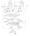
- Reference numeral 1 denotes the control device according to the invention, whose components are arranged within the dot-dashed area. This control device is preferably portable and can therefore be used directly on site depending on the circumstances of the use.
- the control device 1 is provided with a pump 4 and with several, in the case of the drawing figure with two means of resources z. B. hydraulic oil powered tools connected.
- the tools in the present embodiment are a first lifting cylinder 2 and a second lifting cylinder 3, which are operated simultaneously by the single pump 4.
- the two lifting cylinders 2, 3 work in the same direction, ie in the same direction.
- the pump 4 is a motor-driven pump or to a hand pump.
- the operating pressure is for example between about 350 bar and 700 bar.
- the control device 1 serves to allow the operator to coordinate the operation of the two tools as needed using a single pump 4.
- control device 1 comprises a change-over valve 5, with which switch positions can be realized in the example of the drawing FIG. 3, namely crossover (retraction of the tools to the initial position), basic position (no operation of the tools) and parallel position (operation of the tools).
- the inlet from the pump 4 to the switching valve 5 is provided with reference numeral 19.
- the conveyed by the pump 4 resources is returned directly to the return line to the reservoir 18.
- the switching valve 5 is designed such that when the operating element 6 is released by the operator due to a spring arrangement 14, it automatically transitions into the basic position shown centrally in the figure, in which only an unpressurized circulation of the operating medium takes place. Lets the operator thus the control element 6 of the switching valve 5 going on, carried by the provision of the switching valve 5 in the normal position no promotion of the equipment from the switching valve 5 to the tools.
- the control unit 1 further comprises a control valve 7 which is provided between the switching valve 5 and the tools.
- the Pressure medium line between the switching valve 5 and the individual tools thus runs via the control valve. 7
- the control valve 7 is designed as a so-called proportional valve, with the result that the operator over the control element 8 with one hand to divide the volume to be split via the control valve 7 of the pump 4 and the switching valve 5 to the individual tools and thus the individual tools can individually control.
- the operator can operate the control valve 7 in the manner of a joystick control with one hand, wherein it determines the function of the switching valve 5 with the other hand.
- a feeding operating line 10, 11 is provided between the control valve 7 and the respective tool.
- a feeding operating line 10, 11 is provided in each resource line 10, 11 each have a load-holding valve 20, 21 is provided.
- the control device 1 has an independent of the flow divider function of the control valve 7 load-holding function.
- the arrangement shown in the drawing figure consisting of a first lifting cylinder 2 and a second lifting cylinder 3 operated by the control device 1 by a single operator and falls this operator, for example, by fainting out, the controls are 6 and 8 released, whereupon the switching valve. 5 goes to his basic position.
- the control valve 7 remains in the current position, while the load-lock valves 20, 21 come into effect and the lifting cylinders 2, 3 remain in the current position.
- the load-holding check valves 20, 21 no operating medium can flow away to the control valve 7 and to the change-over valve 5 and a load-holding state is established on the tools. There is thus no change in the respective instantaneous position of the first lifting cylinder 2 or the second Lifting cylinder 3.
- the control valve 7 remains in the current position, the operator can immediately operate the control valve 7 starting from the last position when starting work.
- the basic position of the switching valve 5 causes the pump 4 resources are conveyed in a non-pressurized circulation.
- the control valve 7 has only flow divider function, so that conventional proportional valves can be used as control valves, without having to integrate any check valves or other means for recovery in a predetermined basic position.
- the load-retaining valves 20, 21 are hydraulically unlocked, whereby a controlled relief of the tools can be made and a solution of the connectors of the resource lines 10, 11 is made possible with complete relief.
- control line 22 is provided, which connects the load-holding valves 20, 21 with each other, wherein the control line 22 is in communication with the respective return line 12, 13.
- the operating medium lines 10, 11 or the corresponding common extension line and the return lines 12, 13 or the corresponding common entry line is in each case assigned a pressure relief valve 16, 17, so that maximum pressures for the tools or the lifting cylinders 2, 3 each independently In and out can be adjusted. This protects the entire system from overpressure.
- the maximum input or Ausfahrbuch is in the lifting cylinders 2, 3 due their connection to a common line, in which the respective pressure relief valve 16, 17 is arranged, the same.
- the pressure relief valves 16, 17 are each spring-loaded in the embodiment, which is indicated by the spring assembly 15.
- a return valve 9 is provided in the return to the reservoir 18 of the pump 4. This serves as additional security to avoid inadmissible pressure increases in the event that the return line to the reservoir 18 is blocked. From the return valve 9, the equipment can be sprayed into the open air.
- a conventional changeover valve can be used, which can be used without design changes.
- the control valve 7 and / or switching valve 5 can be driven manually or by motor.
- a pump 4 a pump with a plurality of mutually independent resource circuits, such as a so-called dual-flow pump, are used. In the latter case, two lifting cylinders and a rescue scissors could be operated in parallel with the control unit according to the invention.
Landscapes
- Engineering & Computer Science (AREA)
- Physics & Mathematics (AREA)
- Fluid Mechanics (AREA)
- Mechanical Engineering (AREA)
- General Engineering & Computer Science (AREA)
- Fluid-Pressure Circuits (AREA)
Abstract
Description
- Die vorliegende Erfindung betrifft eine Steuereinrichtung gemäß dem Oberbegriff des Anspruchs 1.
- Eine entsprechende Steuereinrichtung ist bereits aus der
EP 1 650 442 B1 bekannt. Das Steuerventil ist als Proportionalventil ausgeführt. Das Steuerventil weist darüber hinaus eine Grundstellung auf, in die sich das Steuerventil selbsttätig bewegt, sofern das Bedienungselement des Steuerventils von der Bedienungsperson losgelassen wird. In dieser Grundstellung werden Rückschlagventile mit den Betriebsmittelleitungen verbunden. Die Rückschlagventile sind hierbei notweniger Bestandteil des Ventilkörpers des Steuerventils. Daraus resultiert der Nachteil, dass zum einen von einer bestimmten Ventilstellung in die Grundstellung übergegangen werden muss, um die Lasthaltefunktion zu gewährleisten, zum anderen die Konstruktion des Steuerventils aufwendig ist. - Die Aufgabe der vorliegenden Erfindung besteht darin, eine neuartige Steuereinrichtung der gattungsgemäßen Art zur Verfügung zu stellen, die die vorstehenden Nachteile vermeidet.
- Die vorstehende Aufgabe wird durch die gesamte Lehre des Anspruchs 1 gelöst. Vorteilhafte Weiterbildungen sind in den Unteransprüchen beansprucht.
- Dadurch, dass in der jeweiligen Betriebsmittelleitung ein Lasthaltesperrventil vorgesehen ist und die Mengenverteilerfunktion des Steuerventils unabhängig von der Lasthaltefunktion ist, setzt die Lasthaltefunktion unabhängig von der Stellung des Steuerventils ein, sofern das Umschaltventil in seine Grundstellung bewegt wird oder sich bewegt. Die Lasthaltefunktion ist daher ausschließlich von der Stellung des Umschaltventils abhängig. Gleichzeitig erlaubt es die Erfindung, die Konstruktion des Steuerventils zu vereinfachen.
- Das Steuerventil besitzt zweckmäßigerweise ausschließlich Mengenteilerfunktion. Es können daher herkömmliche Proportionalventile als Steuerventile verwendet werden.
- Dadurch, dass gemäß einer zweckmäßigen Ausgestaltung das Lasthaltesperrventil hydraulisch entsperrbar ist, kann eine kontrollierte Entlastung der Werkzeuge vorgenommen werden und eine Lösung der Steckverbindungen der Betriebsmittelleitungen bei vollständiger Entlastung ermöglicht werden.
- Anstelle oder zusätzlich zu einer hydraulischen Entsperrung kann auch eine mechanische Entsperrung des Lasthaltesperrventils vorgesehen sein.
- Zur hydraulischen Entsperrung dient zweckmäßigerweise eine gemeinsame Ansteuerleitung, die die Lasthaltesperrventile miteinander verbindet und mit der jeweiligen Rückleitung der Werkzeuge in Verbindung steht.
- In vorteilhafter Weise muss das Steuerventil keinerlei Mittel für eine Veränderung der Stellung des Steuerventils für eine Notfallsituation aufweisen.
- Den Betriebsmittelleitungen bzw. einer gemeinsamen Ausfahrleitung und/oder den Rückleitungen bzw. einer gemeinsamen Einfahrleitung kann jeweils ein Druckbegrenzungsventil zugeordnet sein. Dies bedeutet, dass der Maximaldruck zum Ausfahren der Zylinder anders einstellbar ist als der Maximaldruck zum Einfahren der Zylinder, aber der jeweilige Maximaldruck ist bei beiden Zylindern gleich.
- Das Druckbegrenzungsventil sorgt dafür, dass bei einem Überschreiten eines Maximaldrucks ein zusätzlicher Druckaufbau innerhalb des hydraulischen Systems nicht mehr möglich ist. Hierdurch kann das Gesamtsystem vor Überdruck geschützt werden.
- Zudem kann im Rücklauf zum Reservoir der Pumpe ebenfalls ein Druckbegrenzungsventil zur Rücklaufabsicherung vorgesehen sein, für den Fall, dass sich ein zu großer Druck in diesem Bereich bilden würde.
- Eine zweckmäßige Ausgestaltung der Erfindung wird anhand einer vereinfachten, schematischen Prinzipdarstellung näher erläutert.
- Bezugsziffer 1 kennzeichnet die erfindungsgemäße Steuereinrichtung, deren Komponenten innerhalb der strichpunktierten Fläche angeordnet sind. Diese Steuereinrichtung ist vorzugsweise tragbar und kann daher je nach den gegebenen Umständen des Einsatzes direkt vor Ort eingesetzt werden.
- Die Steuereinrichtung 1 ist mit einer Pumpe 4 sowie mit mehreren, im Falle der Zeichnungsfigur mit zwei mittels Betriebsmittel z. B. Hydrauliköl betriebenen Werkzeugen verbunden.
- Bei den Werkzeugen handelt es sich im vorliegenden Ausführungsbeispiel um einen ersten Hebezylinder 2 sowie einen zweiten Hebezylinder 3, die von der einzigen Pumpe 4 gleichzeitig betrieben werden. In diesem konkreten Fall arbeiten die beiden Hebezylinder 2, 3 gleichsinnig, d.h. in der gleichen Richtung. Bei der Pumpe 4 handelt es sich um eine motorisch angetriebene Pumpe oder um eine Handpumpe. Der Betriebsdruck liegt z.B. zwischen etwa 350 bar und 700 bar.
- Die Steuereinrichtung 1 dient dazu, dass die Bedienungsperson den Betrieb der beiden Werkzeuge unter Verwendung einer einzelnen Pumpe 4 bedarfsweise koordinieren kann.
- Die Steuereinrichtung 1 umfasst hierzu ein Umschaltventil 5, mit dem im Beispiel der Zeichnungsfigur 3 Schaltstellungen realisierbar sind, nämlich Überkreuzstellung (Zurückfahren der Werkzeuge in die Ausgangsstellung), Grundstellung (kein Betrieb der Werkzeuge) sowie Parallelstellung (Betrieb der Werkzeuge). Der Zulauf von der Pumpe 4 zum Umschaltventil 5 ist mit Bezugsziffer 19 versehen. Im Zustand der Grundstellung wird das von der Pumpe 4 beförderte Betriebsmittel unmittelbar in die Rücklaufleitung zum Reservoir 18 zurückgeleitet.
- Die Wahl der jeweiligen Umschaltstellung des Umschaltventils 5 erfolgt über ein Bedienelement 6, das die Bedienungsperson manuell betätigen kann. Das Umschaltventil 5 ist derart konzipiert, dass es bei einem Loslassen des Bedienelements 6 durch die Bedienungsperson bedingt durch eine Federanordnung 14 selbsttätig in die in der Figur mittig dargestellte Grundstellung übergeht, bei der lediglich ein druckloser Umlauf des Betriebsmittels erfolgt. Lässt die Bedienungsperson somit das Bedienelement 6 des Umschaltventils 5 los, erfolgt durch die Rückstellung des Umschaltventils 5 in die Grundstellung keine Förderung des Betriebsmittels vom Umschaltventil 5 zu den Werkzeugen.
- Die erfindungsgemäße Steuereinheit 1 umfasst ferner ein Steuerventil 7, welches zwischen dem Umschaltventil 5 und den Werkzeugen vorgesehen ist. Die Druckmittelleitung zwischen Umschaltventil 5 und den einzelnen Werkzeugen verläuft demzufolge über das Steuerventil 7.
- Das Steuerventil 7 ist als sogenanntes Proportionalventil ausgeführt, mit der Folge, dass die Bedienungsperson über das Bedienelement 8 mit einer Hand die über das Steuerventil 7 aufzuteilenden Volumenströme von der Pumpe 4 bzw. dem Umschaltventil 5 zu den einzelnen Werkzeugen beliebig teilen und damit die einzelnen Werkzeuge individuell ansteuern kann. Die Bedienungsperson kann das Steuerventil 7 nach Art einer Joystick-Steuerung mit der einen Hand bedienen, wobei sie mit der anderen Hand die Funktion des Umschaltventils 5 festlegt.
- Zwischen dem Steuerventil 7 und dem jeweiligen Werkzeug ist eine zuführende Betriebsmittelleitung 10, 11 vorgesehen. In der jeweiligen Betriebsmittelleitung 10, 11 ist jeweils ein Lasthaltesperrventil 20, 21 vorgesehen. Die Steuereinrichtung 1 weist eine von der Mengenteilerfunktion des Steuerventils 7 unabhängige Lasthaltefunktion auf.
- Wird somit die in der Zeichnungsfigur dargestellte Anordnung bestehend aus einem ersten Hebezylinder 2 und einem zweiten Hebezylinder 3 mittels der Steuereinrichtung 1 von einer einzigen Bedienungsperson bedient und fällt diese Bedienungsperson z.B. durch ohnmächtig werden aus, werden die Bedienelemente 6 und 8 losgelassen, woraufhin das Umschaltventil 5 sich in seine Grundstellung begibt. Das Steuerventil 7 verbleibt jedoch in der aktuellen Stellung, während die Lasthaltesperrventile 20, 21 zur Wirkung kommen und die Hebezylinder 2, 3 in der aktuellen Stellung verharren. Durch die Aktivierung der Lasthaltesperrventile 20, 21 kann kein Betriebsmittel zum Steuerventil 7 sowie zum Umschaltventil 5 abfließen und es stellt sich ein lasthaltender Zustand an den Werkzeugen ein. Es ergibt sich somit keine Veränderung der jeweiligen augenblicklichen Position des ersten Hebezylinders 2 bzw. des zweiten Hebezylinders 3. Indem auch das Steuerventil 7 in der aktuellen Stellung verbleibt, kann die Bedienungsperson bei der Arbeitsaufnahme sogleich das Steuerventil 7 ausgehend von der letzten Position weiter bedienen.
- Die Grundstellung des Umschaltventils 5 bewirkt, dass von der Pumpe 4 Betriebsmittel in einen drucklosen Umlauf gefördert werden.
- Das Steuerventil 7 besitzt ausschließlich Mengenteilerfunktion, so dass herkömmliche Proportionalventile als Steuerventile verwendbar sind, ohne dass irgendwelche Rückschlagventile oder andere Mittel zur Rückstellung in eine vorgegebene Grundstellung integriert werden müssen.
- Die Lasthaltesperrventile 20, 21 sind hydraulisch entsperrbar, wodurch eine kontrollierte Entlastung der Werkzeuge vorgenommen werden kann und eine Lösung der Steckverbindungen der Betriebsmittelleitungen 10, 11 bei vollständiger Entlastung ermöglicht wird.
- Ferner ist eine Ansteuerleitung 22 vorgesehen, die die Lasthalteventile 20, 21 miteinander verbindet, wobei die Ansteuerleitung 22 mit der jeweiligen Rückleitung 12, 13 in Verbindung steht.
- Den Betriebsmittelleitungen 10, 11 bzw. der entsprechenden gemeinsamen Ausfahrleitung sowie den Rückleitungen 12, 13 bzw. der entsprechenden gemeinsamen Einfahrleitung ist jeweils ein Druckbegrenzungsventil 16, 17 zugeordnet, so dass maximale Drücke für die Werkzeuge bzw. die Hebezylinder 2, 3 jeweils unabhängig voneinander beim Ein- und Ausfahren eingestellt werden können. Hierdurch wird das Gesamtsystem vor Überdruck geschützt. Der maximale Ein- bzw. Ausfahrdruck ist dabei bei den Hebezylindern 2, 3 aufgrund deren Verbindung zu einer gemeinsamen Leitung, in welcher das jeweilige Druckbegrenzungsventil 16, 17 angeordnet ist, gleich.
- Die Druckbegrenzungsventile 16, 17 sind im Ausführungsbeispiel jeweils federbelastet, was durch die Federanordnung 15 kenntlich gemacht ist.
- Zudem ist im Rücklauf zum Reservoir 18 der Pumpe 4 eine Rücklaufabsicherung 9 vorgesehen. Diese dient als zusätzliche Sicherheit zur Vermeidung von unzulässigen Druckanstiegen für den Fall, dass die Rücklaufleitung zum Reservoir 18 blockiert ist. Von der Rücklaufabsicherung 9 kann das Betriebsmittel ins Freie abgespritzt werden.
- Anstelle von zwei Werkzeugen kann ebenso gut eine größere Anzahl von Werkzeugen vorgesehen sein. Bei dem Umschaltventil 5 kann es sich konzeptionsbedingt in vorteilhafter Weise um ein herkömmliches Umschaltventil handeln, welches ohne konstruktive Änderungen einsetzbar ist. Das Steuerventil 7 und/oder Umschaltventil 5 können manuell oder motorisch angetrieben sein. Als Pumpe 4 kann auch einer Pumpe mit mehreren untereinander unabhängigen Betriebsmittelkreisläufen, so z.B. eine sogenannte Zweistrompumpe, eingesetzt werden. In letzterem Fall könnten mit der erfindungsgemäßen Steuereinheit zwei Hebezylinder und eine Rettungsschere parallel betrieben werden.
-
- 1)
- Steuereinrichtung
- 2)
- Hebezylinder
- 3)
- Hebezylinder
- 4)
- Pumpe
- 5)
- Umschaltventil
- 6)
- Bedienelement
- 7)
- Steuerventil
- 8)
- Bedienelement
- 9)
- Rücklaufabsicherung
- 10)
- Betriebsmittelleitung
- 11)
- Betriebsmittelleitung
- 12)
- Rückleitung
- 13)
- Rückleitung
- 14)
- Federanordnung
- 15)
- Federanordnung
- 16)
- Druckbegrenzungsventil
- 17)
- Druckbegrenzungsventil
- 18)
- Reservoir
- 19)
- Zulauf
- 20)
- Lasthaltesperrventil
- 21)
- Lasthaltesperrventil
- 22)
- Ansteuerleitung
Claims (8)
- Steuereinrichtung (1) mit
einem Umschaltventil (5),
einer Betriebsmittel fördernden Pumpe (4),
insbesondere einer Motorpumpe oder einer Handpumpe, Anschlusseinrichtungen zur Verbindung der Steuereinrichtung (1) mit mindestens zwei Werkzeugen, insbesondere einem ersten Hebezylinder (2) und einem zweiten Hebezylinder (3) oder dergleichen, wobei das Umschaltventil (5) per Hand bedienbar ist, wobei das Umschaltventil (5) in eine Grundstellung bringbar ist, bei der kein Druckaufbau im Bereich der Werkzeuge möglich ist,
zwischen dem Umschaltventil (5) und den Werkzeugen ein Steuerventil (7) vorgesehen ist, welches ein Proportionalventil ist und von einer Bedienungsperson ebenfalls per Hand bedienbar ist und mit dem die mindestens zwei Werkzeuge ansteuerbar sind und
zwischen dem Steuerventil (7) und dem jeweiligen Werkzeug eine Betriebsmittelleitung (10, 11) vorgesehen ist,
dadurch gekennzeichnet, dass(a) in der jeweiligen Betriebsmittelleitung (10, 11) ein Lasthaltesperrventil (20, 21) vorgesehen ist und(b) die Steuereinrichtung (1) eine von der Mengenverteilerfunktion des Steuerventils (7) unabhängige Lasthaltefunktion aufweist. - Steuereinrichtung nach Anspruch 1,
dadurch gekennzeichnet, dass das Steuerventil (7) ausschließlich eine Mengenteilerfunktion besitzt. - Steuereinrichtung nach einem der Ansprüche 1 oder 2,
dadurch gekennzeichnet, dass das Lasthaltesperrventil (20, 21) hydraulisch entsperrbar ist. - Steuereinrichtung nach einem der vorhergehenden Ansprüche,
dadurch gekennzeichnet, dass das Lasthaltesperrventil (20, 21) mechanisch entsperrbar ist. - Steuereinrichtung nach Anspruch 4,
dadurch gekennzeichnet, dass
eine Ansteuerleitung (22) vorgesehen ist, die die Lasthalteventile (20, 21) miteinander verbindet, wobei die Ansteuerleitung (22) mit der jeweiligen Rückleitung (12, 13) in Verbindung steht. - Steuereinrichtung nach einem der vorhergehenden Ansprüche,
dadurch gekennzeichnet, dass
das Steuerventil (7) keine Mittel zur Rückstellung in eine vorgegebene Grundstellung aufweist. - Steuereinrichtung nach einem der vorhergehenden Ansprüche,
dadurch gekennzeichnet, dass
den Betriebsmittelleitungen (10, 11) bzw. einer gemeinsamen Ausfahrleitung und/oder den Rückleitungen (12, 13) bzw. einer gemeinsamen Einfahrleitung ein Druckbegrenzungsventil (16, 17) zugeordnet ist. - Steuereinrichtung nach einem der vorhergehenden Ansprüche,
dadurch gekennzeichnet, dass
im Rücklauf zum Reservoir (18) der Pumpe (4) eine Rücklaufabsicherung (9) vorgesehen ist.
Applications Claiming Priority (1)
| Application Number | Priority Date | Filing Date | Title |
|---|---|---|---|
| DE200910024886 DE102009024886B3 (de) | 2009-06-09 | 2009-06-09 | Steuereinrichtung |
Publications (2)
| Publication Number | Publication Date |
|---|---|
| EP2261512A2 true EP2261512A2 (de) | 2010-12-15 |
| EP2261512A3 EP2261512A3 (de) | 2014-06-04 |
Family
ID=42734791
Family Applications (1)
| Application Number | Title | Priority Date | Filing Date |
|---|---|---|---|
| EP10005628.2A Withdrawn EP2261512A3 (de) | 2009-06-09 | 2010-05-31 | Hydraulische Steuereinrichtung |
Country Status (2)
| Country | Link |
|---|---|
| EP (1) | EP2261512A3 (de) |
| DE (1) | DE102009024886B3 (de) |
Citations (1)
| Publication number | Priority date | Publication date | Assignee | Title |
|---|---|---|---|---|
| EP1650442B1 (de) | 2004-10-20 | 2008-08-06 | Lukas Hydraulik GmbH | Steuereinrichtung |
Family Cites Families (1)
| Publication number | Priority date | Publication date | Assignee | Title |
|---|---|---|---|---|
| JPS57154505A (en) * | 1981-03-13 | 1982-09-24 | Mitsubishi Heavy Ind Ltd | Hydraulic system |
-
2009
- 2009-06-09 DE DE200910024886 patent/DE102009024886B3/de active Active
-
2010
- 2010-05-31 EP EP10005628.2A patent/EP2261512A3/de not_active Withdrawn
Patent Citations (1)
| Publication number | Priority date | Publication date | Assignee | Title |
|---|---|---|---|---|
| EP1650442B1 (de) | 2004-10-20 | 2008-08-06 | Lukas Hydraulik GmbH | Steuereinrichtung |
Also Published As
| Publication number | Publication date |
|---|---|
| DE102009024886B3 (de) | 2010-12-02 |
| EP2261512A3 (de) | 2014-06-04 |
Similar Documents
| Publication | Publication Date | Title |
|---|---|---|
| EP1915538B1 (de) | Schaltung zur ansteuerung eines doppeltwirkenden hydraulischen antriebszylinders | |
| DE10327132A1 (de) | Hydraulikschaltung für eine Ausleger-Zylinder-Kombination, welche eine Umlauffunktion aufweist | |
| EP1780420B1 (de) | Hydraulische Druckversorgungseinheit und elektrohydraulische Arbeitseinheit | |
| EP3931450B1 (de) | Hydraulisches antriebssystem | |
| DE102004052602B4 (de) | Ventilanordnung | |
| DE102004051213B3 (de) | Steuereinrichtung | |
| EP4105496B1 (de) | Hydraulikaggregat zur versorgung hydraulisch antreibbarer rettungsgeräte | |
| EP3058236B1 (de) | Steuervorrichtung | |
| WO2012019758A1 (de) | Steuereinrichtung für erstes und zweites arbeitsgerät | |
| DE2148502B2 (de) | Ein- oder mehrkreisiges Hydrauliksystem | |
| EP3012463B1 (de) | Hydraulikaggregat | |
| EP3625457B1 (de) | Steuervorrichtung zum versorgen mindestens eines hydraulischen verbrauchers mit fluid | |
| EP2825778B1 (de) | Vorrichtung nebst hydrauliksystem zur ansteuerung mindestens eines ersten hydraulischen verbrauchers und mindestens eines zweiten hydraulischen verbrauchers | |
| EP2514977B1 (de) | Steuerungsblock für eine Presse | |
| EP3436705B1 (de) | Steuervorrichtung | |
| DE102009024886B3 (de) | Steuereinrichtung | |
| DE3110220C2 (de) | ||
| EP2541071B1 (de) | Ventilanordnung für ein hydraulisches Steuerungssystem | |
| DE102017206581A1 (de) | Ventilanordnung für Stiel-Zylinder mit zwei Betriebszuständen | |
| EP1239208B1 (de) | Elektro-hydraulischer Schaltungskreis zur Druckentlastung von Schnellkupplungen | |
| DE102016212306A1 (de) | Zwischenblock und Kompaktachse mit einem Zwischenblock | |
| DE202004020878U1 (de) | Steuereinrichtung | |
| DE10011015B4 (de) | Hydraulische Lenkeinrichtung | |
| EP4130493B1 (de) | Hydraulische steueranordnung | |
| EP2600012B1 (de) | Hydrauliksystem |
Legal Events
| Date | Code | Title | Description |
|---|---|---|---|
| PUAI | Public reference made under article 153(3) epc to a published international application that has entered the european phase |
Free format text: ORIGINAL CODE: 0009012 |
|
| AK | Designated contracting states |
Kind code of ref document: A2 Designated state(s): AL AT BE BG CH CY CZ DE DK EE ES FI FR GB GR HR HU IE IS IT LI LT LU LV MC MK MT NL NO PL PT RO SE SI SK SM TR |
|
| AX | Request for extension of the european patent |
Extension state: BA ME RS |
|
| PUAL | Search report despatched |
Free format text: ORIGINAL CODE: 0009013 |
|
| AK | Designated contracting states |
Kind code of ref document: A3 Designated state(s): AL AT BE BG CH CY CZ DE DK EE ES FI FR GB GR HR HU IE IS IT LI LT LU LV MC MK MT NL NO PL PT RO SE SI SK SM TR |
|
| AX | Request for extension of the european patent |
Extension state: BA ME RS |
|
| RIC1 | Information provided on ipc code assigned before grant |
Ipc: F15B 11/00 20060101AFI20140429BHEP |
|
| STAA | Information on the status of an ep patent application or granted ep patent |
Free format text: STATUS: THE APPLICATION IS DEEMED TO BE WITHDRAWN |
|
| 18D | Application deemed to be withdrawn |
Effective date: 20141202 |