EP2261449A1 - Swing arm unit for a side door of a vehicle and a car provided with such a swing arm unit - Google Patents
Swing arm unit for a side door of a vehicle and a car provided with such a swing arm unit Download PDFInfo
- Publication number
- EP2261449A1 EP2261449A1 EP09162421A EP09162421A EP2261449A1 EP 2261449 A1 EP2261449 A1 EP 2261449A1 EP 09162421 A EP09162421 A EP 09162421A EP 09162421 A EP09162421 A EP 09162421A EP 2261449 A1 EP2261449 A1 EP 2261449A1
- Authority
- EP
- European Patent Office
- Prior art keywords
- swing arm
- mounting bracket
- side door
- arm unit
- relation
- Prior art date
- Legal status (The legal status is an assumption and is not a legal conclusion. Google has not performed a legal analysis and makes no representation as to the accuracy of the status listed.)
- Granted
Links
- 230000005540 biological transmission Effects 0.000 claims description 23
- 230000000694 effects Effects 0.000 description 6
- 230000001419 dependent effect Effects 0.000 description 1
- 230000002349 favourable effect Effects 0.000 description 1
- 238000012986 modification Methods 0.000 description 1
- 230000004048 modification Effects 0.000 description 1
Images


Classifications
-
- E—FIXED CONSTRUCTIONS
- E05—LOCKS; KEYS; WINDOW OR DOOR FITTINGS; SAFES
- E05D—HINGES OR SUSPENSION DEVICES FOR DOORS, WINDOWS OR WINGS
- E05D15/00—Suspension arrangements for wings
- E05D15/28—Suspension arrangements for wings supported on arms movable in horizontal plane
-
- E—FIXED CONSTRUCTIONS
- E05—LOCKS; KEYS; WINDOW OR DOOR FITTINGS; SAFES
- E05D—HINGES OR SUSPENSION DEVICES FOR DOORS, WINDOWS OR WINGS
- E05D15/00—Suspension arrangements for wings
- E05D15/06—Suspension arrangements for wings for wings sliding horizontally more or less in their own plane
- E05D15/10—Suspension arrangements for wings for wings sliding horizontally more or less in their own plane movable out of one plane into a second parallel plane
- E05D15/1005—Suspension arrangements for wings for wings sliding horizontally more or less in their own plane movable out of one plane into a second parallel plane the wing being supported on arms movable in horizontal planes
- E05D15/101—Suspension arrangements for wings for wings sliding horizontally more or less in their own plane movable out of one plane into a second parallel plane the wing being supported on arms movable in horizontal planes specially adapted for vehicles
-
- E—FIXED CONSTRUCTIONS
- E05—LOCKS; KEYS; WINDOW OR DOOR FITTINGS; SAFES
- E05D—HINGES OR SUSPENSION DEVICES FOR DOORS, WINDOWS OR WINGS
- E05D3/00—Hinges with pins
- E05D3/06—Hinges with pins with two or more pins
- E05D3/12—Hinges with pins with two or more pins with two parallel pins and one arm
- E05D3/122—Gear hinges
-
- E—FIXED CONSTRUCTIONS
- E05—LOCKS; KEYS; WINDOW OR DOOR FITTINGS; SAFES
- E05F—DEVICES FOR MOVING WINGS INTO OPEN OR CLOSED POSITION; CHECKS FOR WINGS; WING FITTINGS NOT OTHERWISE PROVIDED FOR, CONCERNED WITH THE FUNCTIONING OF THE WING
- E05F15/00—Power-operated mechanisms for wings
- E05F15/60—Power-operated mechanisms for wings using electrical actuators
- E05F15/603—Power-operated mechanisms for wings using electrical actuators using rotary electromotors
- E05F15/611—Power-operated mechanisms for wings using electrical actuators using rotary electromotors for swinging wings
- E05F15/614—Power-operated mechanisms for wings using electrical actuators using rotary electromotors for swinging wings operated by meshing gear wheels, one of which being mounted at the wing pivot axis; operated by a motor acting directly on the wing pivot axis
-
- E—FIXED CONSTRUCTIONS
- E05—LOCKS; KEYS; WINDOW OR DOOR FITTINGS; SAFES
- E05Y—INDEXING SCHEME RELATING TO HINGES OR OTHER SUSPENSION DEVICES FOR DOORS, WINDOWS OR WINGS AND DEVICES FOR MOVING WINGS INTO OPEN OR CLOSED POSITION, CHECKS FOR WINGS AND WING FITTINGS NOT OTHERWISE PROVIDED FOR, CONCERNED WITH THE FUNCTIONING OF THE WING
- E05Y2201/00—Constructional elements; Accessories therefore
- E05Y2201/60—Suspension or transmission members; Accessories therefore
- E05Y2201/606—Accessories therefore
- E05Y2201/62—Synchronisation of transmission members
-
- E—FIXED CONSTRUCTIONS
- E05—LOCKS; KEYS; WINDOW OR DOOR FITTINGS; SAFES
- E05Y—INDEXING SCHEME RELATING TO HINGES OR OTHER SUSPENSION DEVICES FOR DOORS, WINDOWS OR WINGS AND DEVICES FOR MOVING WINGS INTO OPEN OR CLOSED POSITION, CHECKS FOR WINGS AND WING FITTINGS NOT OTHERWISE PROVIDED FOR, CONCERNED WITH THE FUNCTIONING OF THE WING
- E05Y2201/00—Constructional elements; Accessories therefore
- E05Y2201/60—Suspension or transmission members; Accessories therefore
- E05Y2201/622—Suspension or transmission members elements
- E05Y2201/644—Flexible elongated pulling elements; Members cooperating with flexible elongated pulling elements
- E05Y2201/656—Chains
-
- E—FIXED CONSTRUCTIONS
- E05—LOCKS; KEYS; WINDOW OR DOOR FITTINGS; SAFES
- E05Y—INDEXING SCHEME RELATING TO HINGES OR OTHER SUSPENSION DEVICES FOR DOORS, WINDOWS OR WINGS AND DEVICES FOR MOVING WINGS INTO OPEN OR CLOSED POSITION, CHECKS FOR WINGS AND WING FITTINGS NOT OTHERWISE PROVIDED FOR, CONCERNED WITH THE FUNCTIONING OF THE WING
- E05Y2900/00—Application of doors, windows, wings or fittings thereof
- E05Y2900/50—Application of doors, windows, wings or fittings thereof for vehicles
- E05Y2900/53—Application of doors, windows, wings or fittings thereof for vehicles characterised by the type of wing
- E05Y2900/531—Doors
Definitions
- the present invention relates to a swing arm unit for a side door of a vehicle configured to allow a side door of a vehicle to swing outward and rearward with respect to a vehicle body from a closed position to an open position and in the opposite direction from the open position to the closed position.
- the invention also relates to a car provided with such a swing arm unit.
- a front side door extending between the so called A pillar and B pillar of the car body and a rear side door extending between the B pillar and C pillar of the car body.
- the front side door is normally hinged to the A pillar so as to swing out forward when being opened
- the rear side door is normally hinged to the B pillar so as to swing out forward when being opened.
- the conventional hinge of a rear side door of a car is sometimes replaced by a swing arm, which is mounted to the C pillar of the car body so as to allow the rear side door to be opened by moving outward and rearward while remaining essentially in parallel with the adjacent side of the car.
- the rear side door can be completely moved away from the door opening between the B pillar and the C pillar so as to, for instance, make it easier to introduce a wheelchair into the passenger seat through this door opening.
- the object of the present invention is to provide a new and favourable swing arm unit for a side door of a vehicle.
- the swing arm unit of the invention comprises:
- the motor and the reduction gear system are mounted to the swing arm so as to be carried by the swing arm and move together with the swing arm when the swing arm is pivoted in relation to the first mounting bracket about said first pivot axis.
- the actuating means for pivoting the swing arm in relation to the vehicle body i.e. the electric motor and the reduction gear system, are mounted to and carried by the swing arm itself.
- no actuating means need to be mounted between the mounting bracket and the swing arm or between the vehicle body and the swing arm, which will make the swing arm unit compact and easy to install in a conventional private car and also make it possible to design the swing arm unit in such a manner that a swing arm unit of one and the same configuration may fit conventional cars of various models.
- the swing arm unit of the invention can be delivered to the customer in a completely pre-assembled state.
- gear wheels will make it possible to achieve a high gear ratio with a compact design of the reduction gear system.
- the reduction gear system is mounted in an internal space of the swing arm.
- the swing arm unit of the invention can hereby be given a compact design with a limited number of protruding parts and the gear members of the reduction gear system will be located in a protected manner inside the swing arm.
- the pivoting of the swing arm in relation to the first mounting bracket and the pivoting of the second mounting bracket in relation to the swing arm can be achieved by means of one and the same motor, and the sprocket wheels can easily be adapted so as to control the pivoting of the second mounting bracket in such a manner that a side door mounted to the second mounting bracket will remain essentially in parallel with the side of the vehicle when the side door is opened and closed by means of the swing arm unit.
- the flexible transmission member is located in an internal space of the swing arm.
- the flexible transmission member will be located in a protected manner inside the swing arm.
- the first sprocket wheel has a larger diameter than the second sprocket wheel.
- the swing arm unit can be designed to move a rear side door of a car in such a manner between an open position essentially in parallel to the car body and a closed position that the rear side door will first hit the B pillar of the car body with its front edge so as to thereafter swing in relation to the B pillar until its rear edge comes into engagement with the C pillar of the car body.
- the rear side door will consequently move in essentially the same manner as a corresponding rear side door conventionally hinged to the B pillar, which will allow the rear side door to co-operate properly with the front side door and the door pillars when the conventional hinge of the rear side door is replaced by the swing arm unit of the invention.
- the transmission member will be pretensioned during the above-mentioned final part of the closing movement when the rear side door swings in relation to the B pillar until its rear edge comes into engagement with the C pillar.
- the transmission member will remain pretensioned as long as the latch of the side door is engaged, and when the latch is released the rear edge of the side door will be forced a short distance outwards away from the C pillar under the effect of the pretensioning force in the transmission member. This will facilitate the opening of the door.
- the invention also relates to a car having the features defined in claim 10.
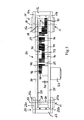
- Fig 1 illustrates a swing arm unit 1 according to an embodiment of the present invention.
- the swing arm unit 1 is to be mounted to a motor vehicle, for instance in the form of a private car of conventional type, in order to carry a side door of the vehicle.
- the swing arm unit 1 is intended to replace the conventional hinge of the side door 2 and is configured to allow the side door to swing outward and rearward with respect to the vehicle body 3 from a closed position (see Fig 7c ) to an open position (see Fig 7a ) and in the opposite direction from the open position to the closed position, while allowing the side door 2 to be positioned essentially in parallel with the adjacent side of the vehicle body 3 when the side door is in the open position.
- the swing arm unit 1 comprises a first mounting bracket 10, which is to be connected to a door pillar 4 (see Fig 4 and Figs7a-7c ) of a vehicle, and a second mounting bracket 20, which is to be connected to a side door 2 of the vehicle.
- a swing arm 30 extends between the first mounting bracket 10 and the second mounting bracket 20.
- the swing arm 30 is connected to the first mounting bracket 10 through a first joint 11 so as to be pivotable in relation to the first mounting bracket 10 about a vertical first pivot axis A1
- the second mounting bracket 20 is connected to the swing arm 30 through a second joint 21 so as to be pivotable in relation to the swing arm 30 about a vertical second pivot axis A2, which extends in parallel with said first pivot axis A1.
- the swing arm 30 has a curved shape as seen in a planar view, with an essentially convex first side 31, which is intended to face away from the side door 2 when the side door is in the closed position (see Fig 7c ), and an essentially concave second side 32, which is located opposite said first side 31 and intended to face the side door 2 when the side door is in the closed position.
- the first mounting bracket 10 comprises a mounting plate 12, which is to be secured to a door pillar 4 of a vehicle.
- An upper arm 13a and a lower arm 13b are secured to the mounting plate 12 and extend therefrom in the direction towards the swing arm 30.
- the second mounting bracket 20 comprises a mounting plate 22, which is to be secured to a side door 2 of a vehicle.
- An upper arm 23a and a lower arm 23b are secured to the mounting plate 22 and extend therefrom in the direction towards the swing arm 30.
- the swing arm 30 is at one end received between the arms 13a, 13b of the first mounting bracket and at the other end received between the arms 23a, 23b of the second mounting bracket.
- the first joint 11 comprises a pivot pin 14, here denominated first pivot pin, which is non-rotatably connected to the first mounting bracket 10 and extends between the arms 13a, 13b thereof.
- An upper end plate 15a is non-rotatably secured to the first pivot pin 14 at the upper end thereof and a lower end plate 15b is non-rotatably secured to the first pivot pin 14 at the lower end thereof.
- the upper end plate 15a is secured to the upper arm 13a of the first mounting bracket, and the lower end plate 15b is secured to the lower arm 13b of the first mounting bracket.
- the second joint 21 comprises a pivot pin 24, here denominated second pivot pin, which is non-rotatably connected to the second mounting bracket 20 and extends between the arms 23a, 23b thereof.
- An upper end plate 25a is non-rotatably secured to the second pivot pin 24 at the upper end thereof and a lower end plate 25b is non-rotatably secured to the first pivot pin 24 at the lower end thereof.
- the upper end plate 25a is secured to the upper arm 23a of the second mounting bracket, and the lower end plate 25b is secured to the lower arm 23b of the second mounting bracket.
- the respective end plate 15a, 15b, 25a, 25b is secured to the associated mounting bracket arm 13a, 13b, 23a, 23b by means of fastening members 16, 26 in the form of screws.
- the swing arm 30 is pivotally mounted to the first pivot pin 14 by means of suitable bearings 17, as illustrated in Fig 5 .
- the swing arm 30 is pivotally mounted to the second pivot pin 24 by means of suitable bearings 27, as illustrated in Fig 6 .
- the swing arm unit 1 comprises an electric motor 33 for pivoting the swing arm 30 in relation to the first mounting bracket 10 about the first pivot axis A1.
- the swing arm unit 1 also comprises a reduction gear system 40, which is configured to act between the motor 33 and the first joint 11 and through which the motor 33 is capable of pivoting the swing arm 30 in relation to the first mounting bracket 10 about the first pivot axis A1.
- the reduction gear system 40 is configured to effect a gear reduction between the output shaft of the motor 33 and the first joint 11.
- the motor 33 and the gear system 40 are mounted to the swing arm 30 so as to be carried by the swing arm and move together with the swing arm when the swing arm is pivoted in relation to the first mounting bracket 10 about the first pivot axis A1.
- the actuating means i.e. the motor 33 and the gear system 40, for pivoting the swing arm 30 in relation to the vehicle body are mounted to and move together with the swing arm.
- the swing arm 30 comprises a top plate 34 and a bottom plate 35 arranged at a distance from and in parallel with each other.
- Side walls 36 are arranged between the top plate 34 and the bottom plate 35 along the edges thereof so as to enclose an internal space inside the swing arm.
- the motor 33 is secured to the bottom plate 35 on the underside thereof, whereas the gear system 40 is mounted in the internal space of the swing arm 30 formed between the top plate 34, the bottom plate 35 and the side walls 36.
- the gear system 40 comprises a gear member 41 which is non-rotatably connected to the first pivot pin 14, and a set of gear wheels acting between the motor 33 and said gear member 41.
- said set of gear wheels comprises a first group of gear wheels arranged in a gear box 42 which is attached to the output shaft of the motor, and a second group of gear wheels 43 mounted to shafts 44 which extend between the top plate 34 and the bottom plate 35 of the swing arm.
- Some of the shafts 44 are provided with a pair of gear wheels 43 of different diameters, the two gear wheels of the pair being connected to each other so as to rotate together.
- the gear wheels 43 are suitably rotatably mounted to the shafts 44 and the shafts 44 non-rotatably mounted to the top and bottom plates 34, 35.
- gear wheels 43 may be non-rotatably mounted to the shafts 44 and the shafts 44 rotatably mounted to the top and bottom plates 34, 35. Said second group of gear wheels 43 are operably connected to the gear box 42 through a gear wheel 45 which is non-rotatably mounted to the output shaft 46 of the gear box.
- One of the gear wheels 43 is suitably displaceable axially or radially out of engagement with the adjacent gear wheels so as to make it possible to operably disconnect the motor 33 and the gear member 41 from each other when there is a need to pivot the swing arm 30 manually in relation to the first mounting bracket 10.
- a manually manoeuvrable operating member (not shown) is provided on the swing arm 30 in order to make possible a movement of said displaceable gear wheel between an engaged position and a disengaged position.
- a first sprocket wheel 18 is non-rotatably mounted to the first pivot pin 14, and a second sprocket wheel 28 is non-rotatably mounted to the second pivot pin 24.
- An elongated flexible transmission member 37 in the form of a sprocket chain or belt runs about said first and second sprocket wheels 18, 28 and is operably connected to them so as to make the second mounting bracket 20 pivot in relation to the swing arm 30 about the second pivot axis A2 when the swing arm 30 is pivoted in relation to the first mounting bracket 10 about the first pivot axis A1.
- a pivoting of the swing arm 30 in relation the first mounting bracket 10 under the effect of the motor 33 and the gear system 40 will also cause a pivoting of the second mounting bracket 20 in relation to the swing arm 30 under the effect of the sprocket wheels 18, 28 and the transmission member 37.
- the control arrangement formed by the sprocket wheels 18, 28 and the transmission member 37 will consequently control the inclination of the side door 2 in relation to the swing arm 30 and the vehicle body 3 when the side door is moved in either direction between its open position and closed position by means of the swing arm unit 1.
- the sprocket wheels 18, 28 and the flexible transmission member 37 are located in the internal space of the swing arm 30 formed between the top plate 34, the bottom plate 35 and the side walls 36.
- the sprocket wheels 18, 28 and the transmission member 37 are with advantage located closely under the top plate 34 of the swing arm 30, as illustrated in Fig 3 .
- the transmission member 37 extends between the first and second sprocket wheels 18, 28 in a first path P1 (see Fig 4 ) facing the convex first side 31 of the swing arm and in a second path P2 facing the concave second side 32 of the swing arm.
- the transmission member 37 is guided along said first and second paths P1, P2 by means of guide pins 39, which extend between the top plate 34 and the bottom plate 35 of the swing arm.
- the first sprocket wheel 18 has a larger diameter than the second sprocket wheel 28.
- the swing arm unit 1 is designed to move the side door 2 in such a manner that the side door 2 extends essentially in parallel with the car body 3 when it is in the open position, as illustrated in Fig 7a .
- the sprocket wheels 18, 28 and the transmission member 37 will make the side door 2 pivot about the second pivot axis A2 in such a manner that the front end 2a of the side door will be inclined inwards towards the vehicle body 3.
- the side door 2 will first hit the B pillar 5 of the vehicle body with its front end 2a, as illustrated in Fig 7b , whereupon the side door 2 will swing in relation to the B pillar 5 until its rear end 2b comes into engagement with the C pillar 4 of the vehicle body, as illustrated in Fig 7c .
- the side door 2 will move in the opposite manner during a movement from the closed position illustrated in Fig 7c to the open position illustrated in Fig 7a .
- the part P1 of the transmission member 37 extending along the convex first side 31 of the swing arm is elastically extendable against the action of a spring force.
- This spring force may for instance be achieved by means of a spring member 38 in the form of a tension spring mounted between two ends of the transmission member 37, as illustrated in Fig 4 .
- the spring member 38 will be pretensioned when the side door 2 swings in relation to the B pillar 5 under the effect of the swing arm 30 from the position illustrated in Fig 7b to the position illustrated in Fig 7c .
- the spring member 38 will remain pretensioned as long as the side door 2 remains in the closed position illustrated in Fig 7c with the latch of the side door engaged.
- the side door 2 When the latch of the side door 2 is released, the side door 2 will swing outward in relation to the B pillar 5 under the effect of the pretensioning force in the spring member 38 and the rear end 2b of the side door will thereby be forced a short distance outwards away from the C pillar 4. This will facilitate the opening of the side door 2.
Abstract
- a first mounting bracket (10) to be connected to a door pillar of the vehicle;
- a second mounting bracket (20) to be connected to the side door;
- a swing arm (30) extending between said mounting brackets;
- an electric motor (33) for pivoting the swing arm in relation to the first mounting bracket; and
- a reduction gear system (40) acting between the motor and the first mounting bracket.
Description
- The present invention relates to a swing arm unit for a side door of a vehicle configured to allow a side door of a vehicle to swing outward and rearward with respect to a vehicle body from a closed position to an open position and in the opposite direction from the open position to the closed position. The invention also relates to a car provided with such a swing arm unit.
- On the respective side of a conventional private car, there is normally a front side door extending between the so called A pillar and B pillar of the car body and a rear side door extending between the B pillar and C pillar of the car body. The front side door is normally hinged to the A pillar so as to swing out forward when being opened, and the rear side door is normally hinged to the B pillar so as to swing out forward when being opened. In order to adapt a conventional private car to the needs of a disabled driver, the conventional hinge of a rear side door of a car is sometimes replaced by a swing arm, which is mounted to the C pillar of the car body so as to allow the rear side door to be opened by moving outward and rearward while remaining essentially in parallel with the adjacent side of the car. Hereby, the rear side door can be completely moved away from the door opening between the B pillar and the C pillar so as to, for instance, make it easier to introduce a wheelchair into the passenger seat through this door opening.
- The object of the present invention is to provide a new and favourable swing arm unit for a side door of a vehicle.
- According to the invention, this object is achieved by a swing arm unit having the features defined in
claim 1. - The swing arm unit of the invention comprises:
- a first mounting bracket to be connected to a door pillar of a vehicle;
- a second mounting bracket to be connected to a side door of a vehicle;
- a swing arm extending between the first mounting bracket and the second mounting bracket, the swing arm being connected to the first mounting bracket through a first joint so as to be pivotable in relation to the first mounting bracket about a first pivot axis, and the second mounting bracket being connected to the swing arm through a second joint so as to be pivotable in relation to the swing arm about a second pivot axis extending in parallel with said first pivot axis;
- an electric motor for pivoting the swing arm in relation to the first mounting bracket about said first pivot axis; and
- a reduction gear system, which is configured to act between the motor and the first joint and through which the motor is capable of pivoting the swing arm in relation to the first mounting bracket about said first pivot axis.
- The motor and the reduction gear system are mounted to the swing arm so as to be carried by the swing arm and move together with the swing arm when the swing arm is pivoted in relation to the first mounting bracket about said first pivot axis.
- Thus, the actuating means for pivoting the swing arm in relation to the vehicle body, i.e. the electric motor and the reduction gear system, are mounted to and carried by the swing arm itself. Hereby, no actuating means need to be mounted between the mounting bracket and the swing arm or between the vehicle body and the swing arm, which will make the swing arm unit compact and easy to install in a conventional private car and also make it possible to design the swing arm unit in such a manner that a swing arm unit of one and the same configuration may fit conventional cars of various models. Furthermore, the swing arm unit of the invention can be delivered to the customer in a completely pre-assembled state.
- According to an embodiment of the invention:
- the first joint comprises a pivot pin non-rotatably connected to the first mounting bracket;
- the reduction gear system comprises a gear member non-rotatably connected to said pivot pin; and
- the reduction gear system comprises a set of gear wheels acting between the motor and said gear member.
- The use of gear wheels will make it possible to achieve a high gear ratio with a compact design of the reduction gear system.
- According to another embodiment of the invention, the reduction gear system is mounted in an internal space of the swing arm. The swing arm unit of the invention can hereby be given a compact design with a limited number of protruding parts and the gear members of the reduction gear system will be located in a protected manner inside the swing arm.
- Another embodiment of the invention is characterized in:
- that the first joint comprises a first pivot pin non-rotatably connected to the first mounting bracket;
- that the second joint comprises a second pivot pin non-rotatably connected to the second mounting bracket;
- that a first sprocket wheel is non-rotatably connected to the first pivot pin;
- that a second sprocket wheel is non-rotatably connected to the second pivot pin; and
- that a flexible transmission member in the form of a sprocket chain or belt runs about said first and second sprocket wheels and is operably connected to them so as to make the second mounting bracket pivot in relation to the swing arm about said second pivot axis when the swing arm is pivoted in relation to the first mounting bracket about said first pivot axis.
- Hereby, the pivoting of the swing arm in relation to the first mounting bracket and the pivoting of the second mounting bracket in relation to the swing arm can be achieved by means of one and the same motor, and the sprocket wheels can easily be adapted so as to control the pivoting of the second mounting bracket in such a manner that a side door mounted to the second mounting bracket will remain essentially in parallel with the side of the vehicle when the side door is opened and closed by means of the swing arm unit.
- According to another embodiment of the invention, the flexible transmission member is located in an internal space of the swing arm. Hereby, the flexible transmission member will be located in a protected manner inside the swing arm.
- According to another embodiment of the invention, the first sprocket wheel has a larger diameter than the second sprocket wheel. Hereby, the swing arm unit can be designed to move a rear side door of a car in such a manner between an open position essentially in parallel to the car body and a closed position that the rear side door will first hit the B pillar of the car body with its front edge so as to thereafter swing in relation to the B pillar until its rear edge comes into engagement with the C pillar of the car body. During the final part of the closing movement, the rear side door will consequently move in essentially the same manner as a corresponding rear side door conventionally hinged to the B pillar, which will allow the rear side door to co-operate properly with the front side door and the door pillars when the conventional hinge of the rear side door is replaced by the swing arm unit of the invention.
- Another embodiment of the invention is characterized in:
- that the swing arm has a first side, which is intended to face away from the side door when the side door is in the closed position, and an opposite second side, which is intended to face the side door when the side door is in the closed position;
- that the transmission member extends between the first and second sprocket wheels in a first path facing said first side of the swing arm and in a second path facing said second side of the swing arm; and
- that the part of the transmission member extending along said first path is elastically extendable against the action of a spring force.
- Hereby, the transmission member will be pretensioned during the above-mentioned final part of the closing movement when the rear side door swings in relation to the B pillar until its rear edge comes into engagement with the C pillar. The transmission member will remain pretensioned as long as the latch of the side door is engaged, and when the latch is released the rear edge of the side door will be forced a short distance outwards away from the C pillar under the effect of the pretensioning force in the transmission member. This will facilitate the opening of the door.
- Further advantages as well as advantageous features of the swing arm unit according to the invention will appear from the following description and the dependent claims.
- The invention also relates to a car having the features defined in
claim 10. - With reference to the appended drawing, a specific description of preferred embodiments of the invention cited as examples follows below. In the drawings:
- Fig 1
- is a perspective view of a swing arm unit according to an embodiment of the present invention,
- Fig 2
- is a perspective view of the swing arm unit of
Fig 1 with a side wall removed, - Fig 3
- is a lateral view of the swing arm unit of
Fig 1 with a side wall removed, - Fig 4
- is a cut planar view from above of the swing arm unit of
Fig 1 , - Fig 5
- is a sectional view illustrating a first joint included in the swing arm unit of
Fig 1 , - Fig 6
- is a sectional view illustrating a second joint included in the swing arm unit of
Fig 1 , and - Fig 7a-7c
- are schematic views illustrating different stages during the movement of a rear side door of a car from an open position to a closed position by means of the swing arm unit of
Fig 1 . -
Fig 1 illustrates aswing arm unit 1 according to an embodiment of the present invention. Theswing arm unit 1 is to be mounted to a motor vehicle, for instance in the form of a private car of conventional type, in order to carry a side door of the vehicle. Theswing arm unit 1 is intended to replace the conventional hinge of theside door 2 and is configured to allow the side door to swing outward and rearward with respect to thevehicle body 3 from a closed position (seeFig 7c ) to an open position (seeFig 7a ) and in the opposite direction from the open position to the closed position, while allowing theside door 2 to be positioned essentially in parallel with the adjacent side of thevehicle body 3 when the side door is in the open position. - The
swing arm unit 1 comprises a first mountingbracket 10, which is to be connected to a door pillar 4 (seeFig 4 andFigs7a-7c ) of a vehicle, and asecond mounting bracket 20, which is to be connected to aside door 2 of the vehicle. Aswing arm 30 extends between the first mountingbracket 10 and the second mountingbracket 20. Theswing arm 30 is connected to the first mountingbracket 10 through a first joint 11 so as to be pivotable in relation to the first mountingbracket 10 about a vertical first pivot axis A1, whereas the second mountingbracket 20 is connected to theswing arm 30 through a second joint 21 so as to be pivotable in relation to theswing arm 30 about a vertical second pivot axis A2, which extends in parallel with said first pivot axis A1. - In the illustrated embodiment, the
swing arm 30 has a curved shape as seen in a planar view, with an essentially convexfirst side 31, which is intended to face away from theside door 2 when the side door is in the closed position (seeFig 7c ), and an essentially concavesecond side 32, which is located opposite saidfirst side 31 and intended to face theside door 2 when the side door is in the closed position. - In the illustrated embodiment, the first mounting
bracket 10 comprises a mountingplate 12, which is to be secured to adoor pillar 4 of a vehicle. An upper arm 13a and alower arm 13b are secured to the mountingplate 12 and extend therefrom in the direction towards theswing arm 30. Thesecond mounting bracket 20 comprises a mountingplate 22, which is to be secured to aside door 2 of a vehicle. Anupper arm 23a and alower arm 23b are secured to the mountingplate 22 and extend therefrom in the direction towards theswing arm 30. Theswing arm 30 is at one end received between thearms 13a, 13b of the first mounting bracket and at the other end received between thearms - The first joint 11 comprises a
pivot pin 14, here denominated first pivot pin, which is non-rotatably connected to the first mountingbracket 10 and extends between thearms 13a, 13b thereof. An upper end plate 15a is non-rotatably secured to thefirst pivot pin 14 at the upper end thereof and alower end plate 15b is non-rotatably secured to thefirst pivot pin 14 at the lower end thereof. The upper end plate 15a is secured to the upper arm 13a of the first mounting bracket, and thelower end plate 15b is secured to thelower arm 13b of the first mounting bracket. The second joint 21 comprises apivot pin 24, here denominated second pivot pin, which is non-rotatably connected to the second mountingbracket 20 and extends between thearms upper end plate 25a is non-rotatably secured to thesecond pivot pin 24 at the upper end thereof and alower end plate 25b is non-rotatably secured to thefirst pivot pin 24 at the lower end thereof. Theupper end plate 25a is secured to theupper arm 23a of the second mounting bracket, and thelower end plate 25b is secured to thelower arm 23b of the second mounting bracket. In the illustrated embodiment, therespective end plate bracket arm fastening members - At its inner end, the
swing arm 30 is pivotally mounted to thefirst pivot pin 14 by means ofsuitable bearings 17, as illustrated inFig 5 . At its outer end, theswing arm 30 is pivotally mounted to thesecond pivot pin 24 by means ofsuitable bearings 27, as illustrated inFig 6 . - The
swing arm unit 1 comprises anelectric motor 33 for pivoting theswing arm 30 in relation to the first mountingbracket 10 about the first pivot axis A1. Theswing arm unit 1 also comprises areduction gear system 40, which is configured to act between themotor 33 and the first joint 11 and through which themotor 33 is capable of pivoting theswing arm 30 in relation to the first mountingbracket 10 about the first pivot axis A1. Thereduction gear system 40 is configured to effect a gear reduction between the output shaft of themotor 33 and the first joint 11. Themotor 33 and thegear system 40 are mounted to theswing arm 30 so as to be carried by the swing arm and move together with the swing arm when the swing arm is pivoted in relation to the first mountingbracket 10 about the first pivot axis A1. Thus, the actuating means, i.e. themotor 33 and thegear system 40, for pivoting theswing arm 30 in relation to the vehicle body are mounted to and move together with the swing arm. - In the illustrated embodiment, the
swing arm 30 comprises atop plate 34 and abottom plate 35 arranged at a distance from and in parallel with each other.Side walls 36 are arranged between thetop plate 34 and thebottom plate 35 along the edges thereof so as to enclose an internal space inside the swing arm. In the illustrated example, themotor 33 is secured to thebottom plate 35 on the underside thereof, whereas thegear system 40 is mounted in the internal space of theswing arm 30 formed between thetop plate 34, thebottom plate 35 and theside walls 36. - The
gear system 40 comprises agear member 41 which is non-rotatably connected to thefirst pivot pin 14, and a set of gear wheels acting between themotor 33 and saidgear member 41. In the illustrated embodiment, said set of gear wheels comprises a first group of gear wheels arranged in agear box 42 which is attached to the output shaft of the motor, and a second group ofgear wheels 43 mounted toshafts 44 which extend between thetop plate 34 and thebottom plate 35 of the swing arm. Some of theshafts 44 are provided with a pair ofgear wheels 43 of different diameters, the two gear wheels of the pair being connected to each other so as to rotate together. Thegear wheels 43 are suitably rotatably mounted to theshafts 44 and theshafts 44 non-rotatably mounted to the top andbottom plates gear wheels 43 may be non-rotatably mounted to theshafts 44 and theshafts 44 rotatably mounted to the top andbottom plates gear wheels 43 are operably connected to thegear box 42 through agear wheel 45 which is non-rotatably mounted to theoutput shaft 46 of the gear box. - One of the
gear wheels 43 is suitably displaceable axially or radially out of engagement with the adjacent gear wheels so as to make it possible to operably disconnect themotor 33 and thegear member 41 from each other when there is a need to pivot theswing arm 30 manually in relation to the first mountingbracket 10. In this case, a manually manoeuvrable operating member (not shown) is provided on theswing arm 30 in order to make possible a movement of said displaceable gear wheel between an engaged position and a disengaged position. - A
first sprocket wheel 18 is non-rotatably mounted to thefirst pivot pin 14, and asecond sprocket wheel 28 is non-rotatably mounted to thesecond pivot pin 24. An elongatedflexible transmission member 37 in the form of a sprocket chain or belt runs about said first andsecond sprocket wheels bracket 20 pivot in relation to theswing arm 30 about the second pivot axis A2 when theswing arm 30 is pivoted in relation to the first mountingbracket 10 about the first pivot axis A1. Thus, a pivoting of theswing arm 30 in relation the first mountingbracket 10 under the effect of themotor 33 and thegear system 40 will also cause a pivoting of the second mountingbracket 20 in relation to theswing arm 30 under the effect of thesprocket wheels transmission member 37. The control arrangement formed by thesprocket wheels transmission member 37 will consequently control the inclination of theside door 2 in relation to theswing arm 30 and thevehicle body 3 when the side door is moved in either direction between its open position and closed position by means of theswing arm unit 1. Thesprocket wheels flexible transmission member 37 are located in the internal space of theswing arm 30 formed between thetop plate 34, thebottom plate 35 and theside walls 36. Thesprocket wheels transmission member 37 are with advantage located closely under thetop plate 34 of theswing arm 30, as illustrated inFig 3 . Thetransmission member 37 extends between the first andsecond sprocket wheels Fig 4 ) facing the convexfirst side 31 of the swing arm and in a second path P2 facing the concavesecond side 32 of the swing arm. Thetransmission member 37 is guided along said first and second paths P1, P2 by means of guide pins 39, which extend between thetop plate 34 and thebottom plate 35 of the swing arm. - In order to make the
side door 2 move in the manner illustrated inFigs 7a-7c , thefirst sprocket wheel 18 has a larger diameter than thesecond sprocket wheel 28. In the example illustrated inFig 7a-7c , theswing arm unit 1 is designed to move theside door 2 in such a manner that theside door 2 extends essentially in parallel with thecar body 3 when it is in the open position, as illustrated inFig 7a . When theswing arm 30 pivots theside door 2 towards its closed position, thesprocket wheels transmission member 37 will make theside door 2 pivot about the second pivot axis A2 in such a manner that thefront end 2a of the side door will be inclined inwards towards thevehicle body 3. Hereby, theside door 2 will first hit theB pillar 5 of the vehicle body with itsfront end 2a, as illustrated inFig 7b , whereupon theside door 2 will swing in relation to theB pillar 5 until itsrear end 2b comes into engagement with theC pillar 4 of the vehicle body, as illustrated inFig 7c . Theside door 2 will move in the opposite manner during a movement from the closed position illustrated inFig 7c to the open position illustrated inFig 7a . In order to allow theswing arm 30 to pivot from the position illustrated inFig 7b to the position illustrated inFig 7c , the part P1 of thetransmission member 37 extending along the convexfirst side 31 of the swing arm is elastically extendable against the action of a spring force. This spring force may for instance be achieved by means of aspring member 38 in the form of a tension spring mounted between two ends of thetransmission member 37, as illustrated inFig 4 . Thespring member 38 will be pretensioned when theside door 2 swings in relation to theB pillar 5 under the effect of theswing arm 30 from the position illustrated inFig 7b to the position illustrated inFig 7c . Thespring member 38 will remain pretensioned as long as theside door 2 remains in the closed position illustrated inFig 7c with the latch of the side door engaged. When the latch of theside door 2 is released, theside door 2 will swing outward in relation to theB pillar 5 under the effect of the pretensioning force in thespring member 38 and therear end 2b of the side door will thereby be forced a short distance outwards away from theC pillar 4. This will facilitate the opening of theside door 2. - The invention is of course not in any way restricted to the embodiments described above. On the contrary, many possibilities to modifications thereof will be apparent to a person with ordinary skill in the art without departing from the basic idea of the invention such as defined in the appended claims.
Claims (10)
- A swing arm unit for a side door of a vehicle configured to allow a side door of a vehicle to swing outward and rearward with respect to a vehicle body from a closed position to an open position and in the opposite direction from the open position to the closed position, the swing arm unit (1) comprising:- a first mounting bracket (10) to be connected to a door pillar of a vehicle,- a second mounting bracket (20) to be connected to a side door of a vehicle,- a swing arm (30) extending between the first mounting bracket (10) and the second mounting bracket (20), the swing arm (30) being connected to the first mounting bracket (10) through a first joint (11) so as to be pivotable in relation to the first mounting bracket (10) about a first pivot axis (A1), and the second mounting bracket (20) being connected to the swing arm (30) through a second joint (21) so as to be pivotable in relation to the swing arm (30) about a second pivot axis (A2) extending in parallel with said first pivot axis (A1), and- an electric motor (33) for pivoting the swing arm (30) in relation to the first mounting bracket (10) about said first pivot axis (A1),
characterized in:- that the swing arm unit (1) comprises a reduction gear system (40), which is configured to act between the motor (33) and the first joint (11) and through which the motor (33) is capable of pivoting the swing arm (30) in relation to the first mounting bracket (10) about said first pivot axis (A1); and- that the motor (33) and the gear system (40) are mounted to the swing arm (30) so as to be carried by the swing arm and move together with the swing arm when the swing arm is pivoted in relation to the first mounting bracket (10) about said first pivot axis (A1). - A swing arm unit according to claim 1, characterized in:- that the first joint (11) comprises a pivot pin (14) non-rotatably connected to the first mounting bracket (10);- that the reduction gear system (40) comprises a gear member (41) non-rotatably connected to said pivot pin (14); and- that the gear system (40) comprises a set of gear wheels acting between the motor (33) and said gear member (41).
- A swing arm unit according to claim 1 or 2, characterized in that the gear system (40) is mounted in an internal space of the swing arm (30).
- A swing arm unit according to any of claims 1-3, characterized in:- that the first joint (11) comprises a first pivot pin (14) non-rotatably connected to the first mounting bracket (10);- that the second joint (21) comprises a second pivot pin (24) non-rotatably connected to the second mounting bracket (20);- that a first sprocket wheel (18) is non-rotatably connected to the first pivot pin (14);- that a second sprocket wheel (28) is non-rotatably connected to the second pivot pin (24); and- that a flexible transmission member (37) in the form of a sprocket chain or belt runs about said first and second sprocket wheels (18, 28) and is operably connected to them so as to make the second mounting bracket (20) pivot in relation to the swing arm (30) about said second pivot axis (A2) when the swing arm (30) is pivoted in relation to the first mounting bracket (10) about said first pivot axis (A1).
- A swing arm unit according to claim 4, characterized in that the sprocket wheels (18, 28) and the flexible transmission member (37) are located in an internal space of the swing arm (30).
- A swing arm unit according to claim 4 or 5, characterized in that the first sprocket wheel (18) has a larger diameter than the second sprocket wheel (28).
- A swing arm unit according to claim 6, characterized in:- that the swing arm (30) has a first side (31), which is intended to face away from the side door when the side door is in the closed position, and an opposite second side (32), which is intended to face the side door when the side door is in the closed position;- that the transmission member (37) extends between the first and second sprocket wheels (18, 28) in a first path (P1) facing said first side (31) of the swing arm and in a second path (P2) facing said second side (32) of the swing arm; and- that the part of the transmission member (37) extending along said first path (P1) is elastically extendable against the action of a spring force.
- A swing arm unit according to claim 7, characterized in that a spring member (38) is provided on the part of the transmission member (37) extending along said first path (P1) so as to provide said spring force.
- A swing arm unit according to claim 7 or 8, characterized in that the swing arm (30) has a curved shape as seen in a planar view, said first side (31) of the swing arm being essentially convex and said second side (32) of the swing arm being essentially concave.
- A car, characterized in that the car comprises a rear side door (2) mounted to a C pillar (4) of the car body by means of a swing arm unit (1) according to any of claims 1-9.
Priority Applications (1)
| Application Number | Priority Date | Filing Date | Title |
|---|---|---|---|
| EP20090162421 EP2261449B1 (en) | 2009-06-10 | 2009-06-10 | Swing arm unit for a side door of a vehicle and a car provided with such a swing arm unit |
Applications Claiming Priority (1)
| Application Number | Priority Date | Filing Date | Title |
|---|---|---|---|
| EP20090162421 EP2261449B1 (en) | 2009-06-10 | 2009-06-10 | Swing arm unit for a side door of a vehicle and a car provided with such a swing arm unit |
Publications (2)
| Publication Number | Publication Date |
|---|---|
| EP2261449A1 true EP2261449A1 (en) | 2010-12-15 |
| EP2261449B1 EP2261449B1 (en) | 2012-08-01 |
Family
ID=41138802
Family Applications (1)
| Application Number | Title | Priority Date | Filing Date |
|---|---|---|---|
| EP20090162421 Active EP2261449B1 (en) | 2009-06-10 | 2009-06-10 | Swing arm unit for a side door of a vehicle and a car provided with such a swing arm unit |
Country Status (1)
| Country | Link |
|---|---|
| EP (1) | EP2261449B1 (en) |
Cited By (6)
| Publication number | Priority date | Publication date | Assignee | Title |
|---|---|---|---|---|
| CN104033053A (en) * | 2014-06-11 | 2014-09-10 | 宁波欧德意自动门有限公司 | Full-automatic gear type hinge mechanism for side hung door |
| EP2623701A3 (en) * | 2012-02-01 | 2014-10-22 | Gebr. Bode GmbH & Co. KG | Assembly of a door leaf and a drive device for moving the door leaf for a passenger vehicle |
| EP3259423A4 (en) * | 2015-02-17 | 2018-10-24 | The Braun Corporation | Automatic door operation |
| WO2021204513A1 (en) * | 2020-04-08 | 2021-10-14 | Vitesco Technologies GmbH | Vehicle door actuator, vehicle door and vehicle |
| DE102021210477A1 (en) | 2021-09-21 | 2023-03-23 | Audi Aktiengesellschaft | Adjusting device for adjusting a vehicle door and vehicle door |
| DE102021210475A1 (en) | 2021-09-21 | 2023-03-23 | Audi Aktiengesellschaft | Adjusting device for adjusting a vehicle door and vehicle door |
Families Citing this family (1)
| Publication number | Priority date | Publication date | Assignee | Title |
|---|---|---|---|---|
| US9789922B2 (en) | 2014-12-18 | 2017-10-17 | The Braun Corporation | Modified door opening of a motorized vehicle for accommodating a ramp system and method thereof |
Citations (5)
| Publication number | Priority date | Publication date | Assignee | Title |
|---|---|---|---|---|
| DE2759372A1 (en) * | 1977-11-18 | 1980-07-10 | Karel Hegr | Motor vehicle sliding door with swivel links - uses four bar linkage actuator with cam for moving door |
| US4462185A (en) | 1982-03-12 | 1984-07-31 | Toyota Shatai Kabushiki Kaisha | Door operating device for a slide door unit |
| US4912806A (en) * | 1987-02-20 | 1990-04-03 | Kabushiki Kaisha Sankyo Seiki Seisakusho | Door check |
| EP1004738B1 (en) * | 1998-11-27 | 2005-02-02 | ISE Industries GmbH | Sliding door with rail guide and a locking device |
| US20060028049A1 (en) * | 2004-08-03 | 2006-02-09 | Lang Steven C | Dual pivot hinge assembly for vehicles |
-
2009
- 2009-06-10 EP EP20090162421 patent/EP2261449B1/en active Active
Patent Citations (5)
| Publication number | Priority date | Publication date | Assignee | Title |
|---|---|---|---|---|
| DE2759372A1 (en) * | 1977-11-18 | 1980-07-10 | Karel Hegr | Motor vehicle sliding door with swivel links - uses four bar linkage actuator with cam for moving door |
| US4462185A (en) | 1982-03-12 | 1984-07-31 | Toyota Shatai Kabushiki Kaisha | Door operating device for a slide door unit |
| US4912806A (en) * | 1987-02-20 | 1990-04-03 | Kabushiki Kaisha Sankyo Seiki Seisakusho | Door check |
| EP1004738B1 (en) * | 1998-11-27 | 2005-02-02 | ISE Industries GmbH | Sliding door with rail guide and a locking device |
| US20060028049A1 (en) * | 2004-08-03 | 2006-02-09 | Lang Steven C | Dual pivot hinge assembly for vehicles |
Cited By (9)
| Publication number | Priority date | Publication date | Assignee | Title |
|---|---|---|---|---|
| EP2623701A3 (en) * | 2012-02-01 | 2014-10-22 | Gebr. Bode GmbH & Co. KG | Assembly of a door leaf and a drive device for moving the door leaf for a passenger vehicle |
| CN104033053A (en) * | 2014-06-11 | 2014-09-10 | 宁波欧德意自动门有限公司 | Full-automatic gear type hinge mechanism for side hung door |
| EP3259423A4 (en) * | 2015-02-17 | 2018-10-24 | The Braun Corporation | Automatic door operation |
| EP3660252A1 (en) * | 2015-02-17 | 2020-06-03 | The Braun Corporation | Automatic door operation |
| WO2021204513A1 (en) * | 2020-04-08 | 2021-10-14 | Vitesco Technologies GmbH | Vehicle door actuator, vehicle door and vehicle |
| DE102021210477A1 (en) | 2021-09-21 | 2023-03-23 | Audi Aktiengesellschaft | Adjusting device for adjusting a vehicle door and vehicle door |
| DE102021210475A1 (en) | 2021-09-21 | 2023-03-23 | Audi Aktiengesellschaft | Adjusting device for adjusting a vehicle door and vehicle door |
| WO2023046435A1 (en) | 2021-09-21 | 2023-03-30 | Brose Fahrzeugteile SE & Co. Kommanditgesellschaft, Coburg | Adjustment device for adjusting a vehicle door, and vehicle door |
| WO2023046436A1 (en) | 2021-09-21 | 2023-03-30 | Brose Fahrzeugteile Se & Co. Kommanditgesellschaft, Bamberg | Adjustment device for adusting a vehicle door, and vehicle door |
Also Published As
| Publication number | Publication date |
|---|---|
| EP2261449B1 (en) | 2012-08-01 |
Similar Documents
| Publication | Publication Date | Title |
|---|---|---|
| EP2261449A1 (en) | Swing arm unit for a side door of a vehicle and a car provided with such a swing arm unit | |
| US7841639B2 (en) | Utility vehicle equipped with extendable cargo bed | |
| US8439421B2 (en) | Fuel lid | |
| US7918492B2 (en) | Vehicle door belt and cam articulating mechanism | |
| US4650241A (en) | Side door hinge mechanism in motor vehicle | |
| US20060230578A1 (en) | Gooseneck hinge assembly for vehicles | |
| US20060028049A1 (en) | Dual pivot hinge assembly for vehicles | |
| JP2001521460A (en) | Integration of car door and chassis | |
| JP4760230B2 (en) | Vehicle hood structure | |
| JP6139861B2 (en) | Locker molding mounting system for automatic step board | |
| EP1188647B1 (en) | Locking device for vehicle hood | |
| CN102619428B (en) | Vehicle door structure | |
| US7086673B2 (en) | Rotating front bumper | |
| CN107206872A (en) | Protection device for inner space | |
| KR100774772B1 (en) | Active hood hinge | |
| EP2433851B1 (en) | Vehicular closure | |
| EP1334856B1 (en) | A mechanism for opening a gull-wing side door of a motor vehicle | |
| JP4290016B2 (en) | Slope device for vehicle | |
| JP4839732B2 (en) | Vehicle hood structure | |
| JP4357462B2 (en) | Vehicle console device | |
| CN210437098U (en) | Driving side storage box | |
| JP2005343367A (en) | Fuel lid mounting structure | |
| JP6315012B2 (en) | Rear body structure of a car with retractable roof | |
| JP4225045B2 (en) | License plate mounting structure | |
| US20130088021A1 (en) | Vehicle Door Mechanism |
Legal Events
| Date | Code | Title | Description |
|---|---|---|---|
| PUAI | Public reference made under article 153(3) epc to a published international application that has entered the european phase |
Free format text: ORIGINAL CODE: 0009012 |
|
| AK | Designated contracting states |
Kind code of ref document: A1 Designated state(s): AT BE BG CH CY CZ DE DK EE ES FI FR GB GR HR HU IE IS IT LI LT LU LV MC MK MT NL NO PL PT RO SE SI SK TR |
|
| AX | Request for extension of the european patent |
Extension state: AL BA RS |
|
| 17P | Request for examination filed |
Effective date: 20110406 |
|
| 17Q | First examination report despatched |
Effective date: 20110516 |
|
| REG | Reference to a national code |
Ref country code: DE Ref legal event code: R079 Ref document number: 602009008597 Country of ref document: DE Free format text: PREVIOUS MAIN CLASS: E05D0015100000 Ipc: E05D0003120000 |
|
| RIC1 | Information provided on ipc code assigned before grant |
Ipc: E05D 15/28 20060101ALI20111024BHEP Ipc: E05F 15/12 20060101ALI20111024BHEP Ipc: E05D 15/10 20060101ALI20111024BHEP Ipc: E05D 3/12 20060101AFI20111024BHEP |
|
| GRAP | Despatch of communication of intention to grant a patent |
Free format text: ORIGINAL CODE: EPIDOSNIGR1 |
|
| GRAS | Grant fee paid |
Free format text: ORIGINAL CODE: EPIDOSNIGR3 |
|
| GRAA | (expected) grant |
Free format text: ORIGINAL CODE: 0009210 |
|
| AK | Designated contracting states |
Kind code of ref document: B1 Designated state(s): AT BE BG CH CY CZ DE DK EE ES FI FR GB GR HR HU IE IS IT LI LT LU LV MC MK MT NL NO PL PT RO SE SI SK TR |
|
| REG | Reference to a national code |
Ref country code: GB Ref legal event code: FG4D |
|
| RAP1 | Party data changed (applicant data changed or rights of an application transferred) |
Owner name: SWED ADAPTATION AB |
|
| REG | Reference to a national code |
Ref country code: CH Ref legal event code: EP Ref country code: AT Ref legal event code: REF Ref document number: 568816 Country of ref document: AT Kind code of ref document: T Effective date: 20120815 |
|
| REG | Reference to a national code |
Ref country code: IE Ref legal event code: FG4D |
|
| REG | Reference to a national code |
Ref country code: DE Ref legal event code: R096 Ref document number: 602009008597 Country of ref document: DE Effective date: 20120920 |
|
| REG | Reference to a national code |
Ref country code: CH Ref legal event code: NV Representative=s name: ZIMMERLI, WAGNER & PARTNER AG |
|
| REG | Reference to a national code |
Ref country code: SE Ref legal event code: TRGR |
|
| REG | Reference to a national code |
Ref country code: NL Ref legal event code: T3 |
|
| REG | Reference to a national code |
Ref country code: AT Ref legal event code: MK05 Ref document number: 568816 Country of ref document: AT Kind code of ref document: T Effective date: 20120801 |
|
| REG | Reference to a national code |
Ref country code: LT Ref legal event code: MG4D Effective date: 20120801 |
|
| PG25 | Lapsed in a contracting state [announced via postgrant information from national office to epo] |
Ref country code: IS Free format text: LAPSE BECAUSE OF FAILURE TO SUBMIT A TRANSLATION OF THE DESCRIPTION OR TO PAY THE FEE WITHIN THE PRESCRIBED TIME-LIMIT Effective date: 20121201 Ref country code: NO Free format text: LAPSE BECAUSE OF FAILURE TO SUBMIT A TRANSLATION OF THE DESCRIPTION OR TO PAY THE FEE WITHIN THE PRESCRIBED TIME-LIMIT Effective date: 20121101 Ref country code: CY Free format text: LAPSE BECAUSE OF FAILURE TO SUBMIT A TRANSLATION OF THE DESCRIPTION OR TO PAY THE FEE WITHIN THE PRESCRIBED TIME-LIMIT Effective date: 20120801 Ref country code: FI Free format text: LAPSE BECAUSE OF FAILURE TO SUBMIT A TRANSLATION OF THE DESCRIPTION OR TO PAY THE FEE WITHIN THE PRESCRIBED TIME-LIMIT Effective date: 20120801 Ref country code: AT Free format text: LAPSE BECAUSE OF FAILURE TO SUBMIT A TRANSLATION OF THE DESCRIPTION OR TO PAY THE FEE WITHIN THE PRESCRIBED TIME-LIMIT Effective date: 20120801 Ref country code: HR Free format text: LAPSE BECAUSE OF FAILURE TO SUBMIT A TRANSLATION OF THE DESCRIPTION OR TO PAY THE FEE WITHIN THE PRESCRIBED TIME-LIMIT Effective date: 20120801 Ref country code: LT Free format text: LAPSE BECAUSE OF FAILURE TO SUBMIT A TRANSLATION OF THE DESCRIPTION OR TO PAY THE FEE WITHIN THE PRESCRIBED TIME-LIMIT Effective date: 20120801 |
|
| PG25 | Lapsed in a contracting state [announced via postgrant information from national office to epo] |
Ref country code: PT Free format text: LAPSE BECAUSE OF FAILURE TO SUBMIT A TRANSLATION OF THE DESCRIPTION OR TO PAY THE FEE WITHIN THE PRESCRIBED TIME-LIMIT Effective date: 20121203 Ref country code: PL Free format text: LAPSE BECAUSE OF FAILURE TO SUBMIT A TRANSLATION OF THE DESCRIPTION OR TO PAY THE FEE WITHIN THE PRESCRIBED TIME-LIMIT Effective date: 20120801 Ref country code: GR Free format text: LAPSE BECAUSE OF FAILURE TO SUBMIT A TRANSLATION OF THE DESCRIPTION OR TO PAY THE FEE WITHIN THE PRESCRIBED TIME-LIMIT Effective date: 20121102 Ref country code: SI Free format text: LAPSE BECAUSE OF FAILURE TO SUBMIT A TRANSLATION OF THE DESCRIPTION OR TO PAY THE FEE WITHIN THE PRESCRIBED TIME-LIMIT Effective date: 20120801 Ref country code: LV Free format text: LAPSE BECAUSE OF FAILURE TO SUBMIT A TRANSLATION OF THE DESCRIPTION OR TO PAY THE FEE WITHIN THE PRESCRIBED TIME-LIMIT Effective date: 20120801 |
|
| PG25 | Lapsed in a contracting state [announced via postgrant information from national office to epo] |
Ref country code: ES Free format text: LAPSE BECAUSE OF FAILURE TO SUBMIT A TRANSLATION OF THE DESCRIPTION OR TO PAY THE FEE WITHIN THE PRESCRIBED TIME-LIMIT Effective date: 20121112 Ref country code: RO Free format text: LAPSE BECAUSE OF FAILURE TO SUBMIT A TRANSLATION OF THE DESCRIPTION OR TO PAY THE FEE WITHIN THE PRESCRIBED TIME-LIMIT Effective date: 20120801 Ref country code: EE Free format text: LAPSE BECAUSE OF FAILURE TO SUBMIT A TRANSLATION OF THE DESCRIPTION OR TO PAY THE FEE WITHIN THE PRESCRIBED TIME-LIMIT Effective date: 20120801 Ref country code: DK Free format text: LAPSE BECAUSE OF FAILURE TO SUBMIT A TRANSLATION OF THE DESCRIPTION OR TO PAY THE FEE WITHIN THE PRESCRIBED TIME-LIMIT Effective date: 20120801 Ref country code: CZ Free format text: LAPSE BECAUSE OF FAILURE TO SUBMIT A TRANSLATION OF THE DESCRIPTION OR TO PAY THE FEE WITHIN THE PRESCRIBED TIME-LIMIT Effective date: 20120801 |
|
| PG25 | Lapsed in a contracting state [announced via postgrant information from national office to epo] |
Ref country code: SK Free format text: LAPSE BECAUSE OF FAILURE TO SUBMIT A TRANSLATION OF THE DESCRIPTION OR TO PAY THE FEE WITHIN THE PRESCRIBED TIME-LIMIT Effective date: 20120801 |
|
| PLBE | No opposition filed within time limit |
Free format text: ORIGINAL CODE: 0009261 |
|
| STAA | Information on the status of an ep patent application or granted ep patent |
Free format text: STATUS: NO OPPOSITION FILED WITHIN TIME LIMIT |
|
| 26N | No opposition filed |
Effective date: 20130503 |
|
| PG25 | Lapsed in a contracting state [announced via postgrant information from national office to epo] |
Ref country code: BG Free format text: LAPSE BECAUSE OF FAILURE TO SUBMIT A TRANSLATION OF THE DESCRIPTION OR TO PAY THE FEE WITHIN THE PRESCRIBED TIME-LIMIT Effective date: 20121101 |
|
| REG | Reference to a national code |
Ref country code: DE Ref legal event code: R097 Ref document number: 602009008597 Country of ref document: DE Effective date: 20130503 |
|
| PG25 | Lapsed in a contracting state [announced via postgrant information from national office to epo] |
Ref country code: MC Free format text: LAPSE BECAUSE OF FAILURE TO SUBMIT A TRANSLATION OF THE DESCRIPTION OR TO PAY THE FEE WITHIN THE PRESCRIBED TIME-LIMIT Effective date: 20120801 |
|
| REG | Reference to a national code |
Ref country code: CH Ref legal event code: NV Representative=s name: WAGNER PATENT AG, CH |
|
| REG | Reference to a national code |
Ref country code: IE Ref legal event code: MM4A |
|
| PG25 | Lapsed in a contracting state [announced via postgrant information from national office to epo] |
Ref country code: IE Free format text: LAPSE BECAUSE OF NON-PAYMENT OF DUE FEES Effective date: 20130610 |
|
| PG25 | Lapsed in a contracting state [announced via postgrant information from national office to epo] |
Ref country code: MT Free format text: LAPSE BECAUSE OF FAILURE TO SUBMIT A TRANSLATION OF THE DESCRIPTION OR TO PAY THE FEE WITHIN THE PRESCRIBED TIME-LIMIT Effective date: 20120801 |
|
| PG25 | Lapsed in a contracting state [announced via postgrant information from national office to epo] |
Ref country code: TR Free format text: LAPSE BECAUSE OF FAILURE TO SUBMIT A TRANSLATION OF THE DESCRIPTION OR TO PAY THE FEE WITHIN THE PRESCRIBED TIME-LIMIT Effective date: 20120801 |
|
| PG25 | Lapsed in a contracting state [announced via postgrant information from national office to epo] |
Ref country code: HU Free format text: LAPSE BECAUSE OF FAILURE TO SUBMIT A TRANSLATION OF THE DESCRIPTION OR TO PAY THE FEE WITHIN THE PRESCRIBED TIME-LIMIT; INVALID AB INITIO Effective date: 20090610 Ref country code: MK Free format text: LAPSE BECAUSE OF FAILURE TO SUBMIT A TRANSLATION OF THE DESCRIPTION OR TO PAY THE FEE WITHIN THE PRESCRIBED TIME-LIMIT Effective date: 20120801 Ref country code: LU Free format text: LAPSE BECAUSE OF NON-PAYMENT OF DUE FEES Effective date: 20130610 |
|
| REG | Reference to a national code |
Ref country code: FR Ref legal event code: PLFP Year of fee payment: 8 |
|
| REG | Reference to a national code |
Ref country code: FR Ref legal event code: PLFP Year of fee payment: 9 |
|
| REG | Reference to a national code |
Ref country code: FR Ref legal event code: PLFP Year of fee payment: 10 |
|
| REG | Reference to a national code |
Ref country code: DE Ref legal event code: R082 Ref document number: 602009008597 Country of ref document: DE Representative=s name: FLACH BAUER & PARTNER PATENTANWAELTE MBB, DE Ref country code: DE Ref legal event code: R082 Ref document number: 602009008597 Country of ref document: DE Representative=s name: FLACH BAUER STAHL PATENTANWAELTE PARTNERSCHAFT, DE |
|
| PGFP | Annual fee paid to national office [announced via postgrant information from national office to epo] |
Ref country code: IT Payment date: 20220620 Year of fee payment: 14 Ref country code: GB Payment date: 20220617 Year of fee payment: 14 |
|
| PGFP | Annual fee paid to national office [announced via postgrant information from national office to epo] |
Ref country code: BE Payment date: 20220613 Year of fee payment: 14 |
|
| PGFP | Annual fee paid to national office [announced via postgrant information from national office to epo] |
Ref country code: FR Payment date: 20220614 Year of fee payment: 14 |
|
| PGFP | Annual fee paid to national office [announced via postgrant information from national office to epo] |
Ref country code: CH Payment date: 20220622 Year of fee payment: 14 |
|
| PGFP | Annual fee paid to national office [announced via postgrant information from national office to epo] |
Ref country code: NL Payment date: 20230616 Year of fee payment: 15 Ref country code: DE Payment date: 20230621 Year of fee payment: 15 |
|
| PGFP | Annual fee paid to national office [announced via postgrant information from national office to epo] |
Ref country code: SE Payment date: 20230616 Year of fee payment: 15 |
|
| REG | Reference to a national code |
Ref country code: CH Ref legal event code: PL |
|
| REG | Reference to a national code |
Ref country code: BE Ref legal event code: MM Effective date: 20230630 |
|
| GBPC | Gb: european patent ceased through non-payment of renewal fee |
Effective date: 20230610 |