EP2260203B1 - Kronenspitze für ein laufrad einer wasserturbine sowie ein laufrad und eine wasserturbine mit besagter kronenspitze - Google Patents
Kronenspitze für ein laufrad einer wasserturbine sowie ein laufrad und eine wasserturbine mit besagter kronenspitze Download PDFInfo
- Publication number
- EP2260203B1 EP2260203B1 EP09722746.6A EP09722746A EP2260203B1 EP 2260203 B1 EP2260203 B1 EP 2260203B1 EP 09722746 A EP09722746 A EP 09722746A EP 2260203 B1 EP2260203 B1 EP 2260203B1
- Authority
- EP
- European Patent Office
- Prior art keywords
- skirt
- wheel
- fin
- edge
- member according
- Prior art date
- Legal status (The legal status is an assumption and is not a legal conclusion. Google has not performed a legal analysis and makes no representation as to the accuracy of the status listed.)
- Not-in-force
Links
Images


Classifications
-
- F—MECHANICAL ENGINEERING; LIGHTING; HEATING; WEAPONS; BLASTING
- F03—MACHINES OR ENGINES FOR LIQUIDS; WIND, SPRING, OR WEIGHT MOTORS; PRODUCING MECHANICAL POWER OR A REACTIVE PROPULSIVE THRUST, NOT OTHERWISE PROVIDED FOR
- F03B—MACHINES OR ENGINES FOR LIQUIDS
- F03B3/00—Machines or engines of reaction type; Parts or details peculiar thereto
- F03B3/02—Machines or engines of reaction type; Parts or details peculiar thereto with radial flow at high-pressure side and axial flow at low-pressure side of rotors, e.g. Francis turbines
-
- F—MECHANICAL ENGINEERING; LIGHTING; HEATING; WEAPONS; BLASTING
- F03—MACHINES OR ENGINES FOR LIQUIDS; WIND, SPRING, OR WEIGHT MOTORS; PRODUCING MECHANICAL POWER OR A REACTIVE PROPULSIVE THRUST, NOT OTHERWISE PROVIDED FOR
- F03B—MACHINES OR ENGINES FOR LIQUIDS
- F03B11/00—Parts or details not provided for in, or of interest apart from, the preceding groups, e.g. wear-protection couplings, between turbine and generator
- F03B11/04—Parts or details not provided for in, or of interest apart from, the preceding groups, e.g. wear-protection couplings, between turbine and generator for diminishing cavitation or vibration, e.g. balancing
-
- F—MECHANICAL ENGINEERING; LIGHTING; HEATING; WEAPONS; BLASTING
- F03—MACHINES OR ENGINES FOR LIQUIDS; WIND, SPRING, OR WEIGHT MOTORS; PRODUCING MECHANICAL POWER OR A REACTIVE PROPULSIVE THRUST, NOT OTHERWISE PROVIDED FOR
- F03B—MACHINES OR ENGINES FOR LIQUIDS
- F03B3/00—Machines or engines of reaction type; Parts or details peculiar thereto
- F03B3/12—Blades; Blade-carrying rotors
- F03B3/125—Rotors for radial flow at high-pressure side and axial flow at low-pressure side, e.g. for Francis-type turbines
-
- F—MECHANICAL ENGINEERING; LIGHTING; HEATING; WEAPONS; BLASTING
- F05—INDEXING SCHEMES RELATING TO ENGINES OR PUMPS IN VARIOUS SUBCLASSES OF CLASSES F01-F04
- F05B—INDEXING SCHEME RELATING TO WIND, SPRING, WEIGHT, INERTIA OR LIKE MOTORS, TO MACHINES OR ENGINES FOR LIQUIDS COVERED BY SUBCLASSES F03B, F03D AND F03G
- F05B2260/00—Function
- F05B2260/96—Preventing, counteracting or reducing vibration or noise
-
- Y—GENERAL TAGGING OF NEW TECHNOLOGICAL DEVELOPMENTS; GENERAL TAGGING OF CROSS-SECTIONAL TECHNOLOGIES SPANNING OVER SEVERAL SECTIONS OF THE IPC; TECHNICAL SUBJECTS COVERED BY FORMER USPC CROSS-REFERENCE ART COLLECTIONS [XRACs] AND DIGESTS
- Y02—TECHNOLOGIES OR APPLICATIONS FOR MITIGATION OR ADAPTATION AGAINST CLIMATE CHANGE
- Y02E—REDUCTION OF GREENHOUSE GAS [GHG] EMISSIONS, RELATED TO ENERGY GENERATION, TRANSMISSION OR DISTRIBUTION
- Y02E10/00—Energy generation through renewable energy sources
- Y02E10/20—Hydro energy
Definitions
- the present invention relates to a member adapted to be attached to the ceiling of a hydraulic machine wheel.
- the invention also relates to a wheel equipped with such a member, and to a hydraulic machine comprising such a wheel.
- GB-A-739,013 discloses a Francis wheel equipped with a cone which carries fins arranged radially outside the surface of the cone. At certain speeds, these fins can disturb the path of a flow that licks the outer surface of the cone.
- the invention intends to remedy more particularly by proposing a new member that can be attached to the ceiling of a wheel and that makes it possible to reduce and / or eliminate the instabilities due to turbulent torches, especially under low charge.
- the invention relates to a member adapted to be attached to the ceiling or the hub of a hydraulic machine wheel, this member being provided with a skirt whose surface is adapted to be arranged in the extension of a wet surface of the ceiling or hub.
- This member is equipped with at least one fin disposed radially inside the aforementioned skirt, whereas this fin projects axially downwardly when the member is attached to the wheel, with respect to a lower edge free of the skirt which delimits an opening allowing the flow of water to or from the interior volume of the skirt and in that the portion of the or each fin which protrudes downwardly relative to the free edge of the skirt makes it possible to affect the flow in the vicinity of the axis of rotation of the wheel.
- the fin or fins do not have to have a complex blade shape, which facilitates the design and manufacture of an organ according to the invention.
- acting locally on the vortices or turbulence in the vicinity of the axis of rotation of the wheel does not significantly reduce the overall efficiency of the installation.
- an organ according to the invention may incorporate one or more of the features of claims 2 to 13, taken in any technically permissible combination.
- the invention also relates to a hydraulic machine wheel equipped with a member as described above.
- a wheel has better hydraulic characteristics and makes it possible to change the hydrodynamic structure of turbulent torches which tend to develop near its axis of rotation.
- the invention relates to a hydraulic machine equipped with a wheel as mentioned above.
- a machine may be a turbine, a pump or a turbine pump.
- the machine is advantageously equipped with means for controlling the adjustment means according to parameters of a flow which passes through the wheel.
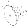
- the Francis turbine wheel 1 shown in FIG. figure 1 is intended to be part of a Francis type turbine T by being connected to a shaft 2 mobile in rotation about a vertical axis Z. This wheel is fed from a sheet 3 belonging to an installation comprising the turbine T and for converting hydraulic energy into electrical or mechanical energy, depending on the equipment to which the shaft 2 is connected at the top.
- the wheel 1 comprises blades 11 regularly distributed around the central axis Z 1 of the wheel which coincides with the Z axis in the installed configuration of the turbine T.
- a ceiling 12 is provided at the upper and inner radial portion of the wheel 1, while a belt 13 borders the lower and outer radial portions of the blades 11.
- a flow conduit is created between each pair of two adjacent blades 11, this duct being delimited by the blades 11, by a wet surface 121 of the ceiling 12 and a wet surface 131 of the belt 13.
- a flow E can thus pass through the wheel 1, acting on the blades 11, to rotate it about the axes Z 1 and Z together to drive the shaft 2.
- a member 4 forming a tip is mounted on the downstream portion 122 of the ceiling 12. This member 4 partially closes the access downstream to the internal volume V 12 of the ceiling 12, this volume generally having to remain, before introduction of the 4 member, accessible for mounting the wheel 1, in particular for attachment to the shaft 2, by means of not shown bolts.
- the body 4 is called “tip” according to practice.
- the tip 4 comprises a disk-shaped flange 41 intended to be fixed on the ceiling 12, for example by means of bolts (not shown).
- the tip 4 also comprises a skirt 42 centered on a Z axis 4 , frustoconical and convergent towards the Z axis 4 away from the flange 41. Note respectively 421 and 422 radial outer and inner surfaces of the skirt 42.
- the skirt 42 is welded to the flange 41 in the vicinity of its outer radial edge 411.
- the terms “high”, “low”, “upper” and “lower” correspond to the orientation of the parts of the wheel 1 when it is in the configuration of use in a turbine T vertical axis .
- an “upper” part is located above a “lower” part.
- the surface 421 extends the surface 121, which contributes to the guidance of the flow E as it passes through the wheel.
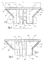
- D 423 is the top edge of the skirt 42 and 424 its lower edge. We denote D 423 and D 424 diameters of the edges 423 and 424. The D 424 value is less than the value of D 423.
- each fin 43 matches the inner shape of the skirt 42 and the lower surface 412 of the flange 41 In other words, an outer edge 431 of each fin 43 adjoins the inner surface 422 of the skirt 42, while an upper edge 432 of this skirt abuts the surface 412.
- Each fin 43 can thus be welded to the flange. 41 and the skirt 42, radially inside this skirt.
- Each fin 43 is centered on a plane P 4 which extends radially with respect to the axis Z 4 . Thus, each fin 43 extends in a radial direction relative to the axis Z 4 .
- each fin 43 is parallel to the axis Z 4 and extends at a distance d 1 from the axis Z 4 which is non-zero, which leaves access to a central opening 413 of the flange. 41 from below, when the tip 4 is mounted on the wheel 1. This provides access to the fixing means of the tip 4 on the wheel 1.
- Each fin 43 comprises a portion 434 projecting axially below the edge 424 of the skirt 42, that is to say which extends, with respect to the flange 41, beyond the skirt 42. 435 the lower edge of a portion 434, this edge being, in the example of Figures 1 to 5 perpendicular to the Z axis 4 .
- Note d 2 the distance between the surface 412 and the edge 435 taken parallel to the Z axis 4 .
- D 3 is the distance rating, also measured parallel to the Z axis 4, between the surface 412 and the 424.
- the distance d 2 is greater than the distance d 3 , so that the portion 434 of each fin 43 exceeds below the skirt 42, over a height h equal to the difference between d 2 and d 3 .
- the portions 434 of the fins 43 protruding from the skirt 42 downwards make it possible to print at a portion E 1 of the flow E, which passes in the vicinity of the surfaces 121 and 421, a movement resulting from the rotation of the tip 4.
- This makes it possible to substantially reduce, or even eliminate, the swirling torches that would tend to develop, especially under low load, in the vicinity of the Z axis, in the area represented in gray at the figure 1 downstream of the wet surfaces 121 and 421.
- edges 433 and 436 are rounded, with a half-disc section of radius which depends on the thickness of the fins 43.
- each fin located axially at the skirt 42, that is to say between the edges 423 and 424, and radially inside thereof.
- the edges 431 and 432 of the portion 437 abut the surfaces 422 and 412.
- a fin 43 is formed from the union of its portions 434 and 437.
- the tip 4 of this embodiment is equipped with four fins 43 which protrude axially below a frustoconical skirt 42, over a height h which is adjustable insofar as the fins 43 are movably mounted relative to the flange 41. and at the skirt 42 of the tip 4, as represented by the double arrows F 1 at the figure 6 .
- each fin 43 is controlled by a servomotor 63 disposed in the central volume V 12 of the ceiling 12 and controlled by a drive unit 7 for driving the turbine T.
- This unit 7 is capable of addressing each of the servomotors 63 a control signal S 7 which can take into account the parameters of the flow E in the wheel 1. These parameters may include the flow rate or water velocity of the flow E, or other parameters.
- the unit 7 controls the guides 8 of the installation to which the turbine T belongs by means of a signal S 8 .
- the unit 7 can analyze a signal S ' 8 communicating to it the position of a director for controlling the servomotors 63 as a function of this signal S 8 .
- the position signal S ' 8 of the directors can be interpreted by the unit 7 to drive the servomotors 63 by means of the signal S 7 , since the signal S 8 is representative of the flow E.
- the signals S 7 can be individualized, so that the relative position of the edge 435 of a fin relative to the edge 424, that is to say the height h, can be different from a fin to the other.
- the axial height h in which the portions 434 of the fins 43 project beyond the skirt 42 can be adjusted, while the tip 4 is mounted on the wheel 2.
- the outer radial edge of the portions 434 is noted 434.
- the edge 436 is not parallel to the central axis Z 4 of the tip 4 but converges toward this axis while approaching the lower edge 435 of the fins 43.
- half-angle at the apex ⁇ of the edge 436 may be chosen as a function of the half-angle at the apex ⁇ of the surface 421.
- the tip 4 of this embodiment also comprises four fins 43 whose portions 434 project beyond a frustoconical skirt 42 over a non-zero height h.
- the outer radial edge 436 of the portions 434 is curved, in the extension of the outer surface 421 of the skirt 42.
- the fins 43 which are flat, are each centered on a plane P 43 parallel to a plane P 4 radial to the central axis Z 4 of the tip 4.
- the fins 43 are parallel to radial directions corresponding to the planes P 4 in the plane of the figure 7 , but shifted laterally with respect to these directions, by a non-zero distance d 5 .
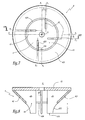
- Wheel 1 of this embodiment is intended to be part of a Francis type T turbine being connected to a rotating shaft 2 about a vertical axis Z.
- the wheel 1 comprises blades 11 which extend between a ceiling 12 and a belt 13.
- the ceiling 12 defines a wet surface 121 intended to be licked by a flow E passing through the wheel 1.
- An element 4 which is referred to as "tip” in the following, is mounted on the downstream part 122 of the ceiling 12 and comprises a disk-shaped flange 41 which is intended to be fixed on the ceiling 12 by means of screw 47 passing through orifices 417 formed in the flange 41.
- Other means of fixing the member 4 on the wheel 1 may be considered in the context of the present invention.
- the tip 4 also comprises an annular skirt 42 centered on a Z axis 4 intended to be coincident with the Z axis in the mounted configuration of the tip 4 and the wheel 1.
- This skirt is frustoconical and convergent towards this axis in s away from the flange 41.
- the outer and inner radial surfaces of the skirt 42 are respectively denoted 421 and 422.
- the skirt 42 is suspended from the flange 41 by four elements 43 in the form of planar fins which each extend parallel to a radial direction relative to the axis Z 4 .
- the skirt 42 is positioned relative to the ceiling 12 so that its outer surface 421 is generally in the extension of the wet surface 121 when the member 4 is mounted on the wheel 1.
- an opening 44 is formed between the flange 41 and the skirt 42.
- the upper edge 423 of the skirt 42 extends at a non-zero distance d from the external radial edge 411 of the flange 41. This distance d is the axial height of the opening 44, taken parallel to the axis Z 4 .
- the opening 44 allows a portion E 1 of the flow E which licks the surface 121 to engage in the internal volume V 4 of the tip 4, that is to say the internal volume of the skirt 42.
- the flow E 1 passes around the skirt 42, both along the surface 421 and along the surface 422, which generally extend the surface 121, being slightly downwardly offset therefrom.
- the edges 431 of the fins 43 which extend axially at the level of the skirt 42 are adjacent to its internal surface 422.
- the fins 43 protrude below the lower edge 424 of the skirt 42 over a height h. 434 is the portion of the fins 43 which protrudes from the skirt 42 downwards, when the tip 4 is attached to the wheel 1.
- the outer radial edge 436 of the wing portion 434 43 protruding below the skirt 42 does not protrude radially and away from the Z axis 4 substantially by relative to the lower edge 424 of the skirt 42.
- the action of the fins 43 is concentrated on the central portion of the flow E 1 shown in FIGS. figures 1 and 6 which goes towards the zone represented in gray on these figures.
- the geometry of the fins 43 of the various embodiments described above is adapted to that of the wheel 1 and the nature of the flow that passes through it.
- the invention has been shown with planar fins 43.
- these fins can be curved with a relatively simple geometry.
- the number of fins 43 of a point 4 is not necessarily equal to four.
- a tip with a single fin can be considered, as can a tip with two, three or more fins. When several fins are used, they are advantageously regularly distributed around the central axis of the skirt.
- the lower edge 435 of the fins 43 may not be perpendicular to the axis Z 4 .
- this edge may be oblique or curved, or even be the bottom of the edge 436.
- the outer surface 421 of the skirt 42 converges toward the Z axis 4 when moving away from the edge 423, i.e. away from the surface 121 in the mounted configuration of the member 4 on the wheel 1.
- the surface 421 is frustoconical straight generatrix. It could also have a curve generator or not converge towards the Z axis 4 , moving away from the edge 423.
- a tip member 4 may be mounted on a wheel 1 while being axially movable, along the axes Z, Z 1 and Z 4 which are then confused. This makes it possible to adapt the position of the surfaces 421 and possibly fins 43, to the operating conditions of the wheel 1.
- This movement of the surface 421, that is to say the skirt 42 in the four embodiments, can be obtained by means of servomotors installed in the interior volume V 12 of the wheel ceiling, like the servo motors 63 of the second embodiment.
- the fins 43 can be provided also retractable that is to say movable upwards relative to the surface 421 of the member 4.
- some fins may be rigidly assembled to the skirt 42 which they support, without passing beyond them, while other fins are movable relative to this skirt and may extend beyond them.
- the means for adjusting the axial position of the skirt 42 with respect to the remainder of the wheel 1 are advantageously controlled according to the parameters of the flow E which passes through the wheel, like the servo motors 63 of the second embodiment.
- the skirt 42 is open downward, in that its lower edge is free and defines an opening 45 allowing the flow of water to or from the interior volume of the skirt 42.
- the water can recirculate to this volume through the opening 45.
- the invention has been shown with a member 4 provided with a mounting flange 41 on a wheel 1 disc-shaped.
- a flange is not necessarily disk-shaped and may be replaced by other connecting parts to the ceiling or hub of the wheel.
- the invention has been shown with a tip 4 bolted to the ceiling 12 of the wheel. Such a tip can be reported differently on the wheel, for example welded.
- the invention is also applicable in the case where the organ forming tip is an integral part of the wheel 1 being integral with the ceiling it extends.
- the fins 43 may be contiguous in the central portion of the internal volume of the skirt 42.
- the fins can meet, their edges 433 being then confounded. They then form parallel channels. These channels can be used to direct the part of the flow E 1 passing radially inside the skirt 42, in the embodiment of Figures 9 to 11 .
- the fins of the first, third and fourth embodiments can be mounted on the tip with a possibility of height adjustment, like the fins of the second embodiment.
- two fins may be fixed and support the skirt 42, without exceeding beyond the edge 424, while two other fins are movable parallel to the axis Z 4 , both in relation to at the flange 41 and at the skirt 42.
- the invention has been represented during its implementation of a Francis-type wheel. However, it is applicable to other types of hydraulic machines, including propeller, Deriaz or Kaplan. In this case, the body of the invention is hooked on the hub of the turbine or the pump.
Landscapes
- Engineering & Computer Science (AREA)
- Chemical & Material Sciences (AREA)
- Combustion & Propulsion (AREA)
- Mechanical Engineering (AREA)
- General Engineering & Computer Science (AREA)
- Hydraulic Turbines (AREA)
- Hydraulic Motors (AREA)
- Soil Working Implements (AREA)
- Forging (AREA)
Claims (16)
- Bauteil (4), das an die Decke (12) oder die Nabe eines Laufrads (1) einer hydraulischen Maschine (T) angesetzt werden kann, wobei dieses Bauteil mit einer Schürze (42) versehen ist, von der eine Fläche (421) in der Verlängerung einer benetzten Fläche (121) der Decke oder der Nabe angeordnet sein kann, wobei das Bauteil mit mindestens einem Flügel (43) ausgestattet ist, der radial im Inneren der Schürze (42) angeordnet ist, dadurch gekennzeichnet, dass dieser Flügel, wenn das Bauteil an das Laufrad angesetzt ist, bezüglich eines freien unteren Rands (424) der Schürze axial (h) nach unten übersteht, der eine Öffnung (45) begrenzt, welche das Fließen des Wassers zum oder ausgehend vom inneren Volumen der Schürze erlaubt, und dass der Teil (434) des oder jedes Flügels (43), der bezüglich des freien Rands (424) der Schürze (42) nach unten übersteht, es ermöglicht, das Fließen in der Nähe der Drehachse (Z) des Laufrads (1) zu beeinflussen.
- Bauteil nach Anspruch 1, dadurch gekennzeichnet, dass der oder jeder Flügel (43) in seinem Bereich (434), der bezüglich der Schürze (42) axial nach unten übersteht, einen äußeren radialen Rand (436) hat, der in radialer Richtung nicht wesentlich über den unteren Rand der Schürze (424) weg von der Mittelachse (Z4) der Schürze übersteht.
- Bauteil nach einem der Ansprüche 1 oder 2, dadurch gekennzeichnet, dass der Flügel oder jeder Flügel sich parallel zu einer radialen Richtung (P4) bezüglich der Symmetrieachse (Z4) der Schürze (42) erstreckt.
- Bauteil nach einem der Ansprüche 1 bis 3, dadurch gekennzeichnet, dass ein Teil (437) des oder jedes Flügels (43) sich axial innerhalb der Schürze (42) erstreckt.
- Bauteil nach Anspruch 4, dadurch gekennzeichnet, dass ein Rand (431) des Teils (437) des oder jedes Flügels (43), der sich im Inneren der Schürze (42) erstreckt, an die Innenfläche (422) der Schürze angrenzt.
- Bauteil nach einem der Ansprüche 4 oder 5, dadurch gekennzeichnet, dass ein Rand (432) des Flügels oder jedes Flügels an eine Fläche (412) eines Befestigungsflanschs (41) des Bauteils (4) an der Decke (12) oder Nabe des Laufrads (1) angrenzt, wobei diese Fläche (412) nach unten gerichtet ist, wenn das Bauteil (4) an das Laufrad angesetzt ist.
- Bauteil nach Anspruch 6, dadurch gekennzeichnet, dass jeder Flügel (43) radial innerhalb der Schürze auf den Flansch (41) und auf die Schürze (42) geschweißt wird.
- Bauteil nach einem der vorhergehenden Ansprüche, dadurch gekennzeichnet, dass die Länge (h), über die ein Element axial von der Wand übersteht, einstellbar ist (F1).
- Bauteil nach Anspruch 8, dadurch gekennzeichnet, dass es Einrichtungen (63) zur Einstellung (F1), wenn das Bauteil (4) an das Laufrad (1) angesetzt wird, der axialen Stellung (h) des Elements (43) bezüglich der Schürze (42) enthält.
- Bauteil nach einem der vorhergehenden Ansprüche, dadurch gekennzeichnet, dass die Schürze (42) bezüglich des Laufrads (1) parallel zu ihrer Mittelachse (Z4) beweglich ist, wenn das Bauteil (4) an das Laufrad montiert wird.
- Bauteil nach einem der vorhergehenden Ansprüche, dadurch gekennzeichnet, dass jeder Flügel (43) mit einem Rand (435) lotrecht zur Mittelachse (Z4) der Schürze versehen ist, der sich in Abstand (h) zum unteren Rand (424) der Schürze (42) und unter diesem Rand erstreckt.
- Bauteil nach einem der vorhergehenden Ansprüche, dadurch gekennzeichnet, dass jeder Flügel (43) mit einem freien Rand (433) parallel zur Mittelachse (Z4) der Schürze versehen ist, der sich in einem Abstand (d1) von dieser Achse erstreckt.
- Bauteil nach einem der Ansprüche 1 bis 11, dadurch gekennzeichnet, dass die Flügel (43) in einem zentralen Bereich des inneren Volumens der Schürze (42) miteinander verbunden sind.
- Laufrad (1) einer hydraulischen Maschine (T), das mit einem Bauteil (4) nach einem der vorhergehenden Ansprüche ausgestattet ist.
- Hydraulische Maschine (T), die mit einem Laufrad (1) nach Anspruch 14 ausgestattet ist.
- Hydraulische Maschine nach Anspruch 15, dadurch gekennzeichnet, dass das Bauteil (4) gemäß Anspruch 9 und/oder Anspruch 10 ist, und dass die Maschine (T) mit Einrichtungen (7) zum Steuern (S7) der Einstelleinrichtungen (63) der Stellung des Elements (43) oder der Schürze (42) abhängig von den Parametern (S'8) einer das Laufrad (1) durchquerenden Strömung (E) ausgestattet ist.
Priority Applications (1)
| Application Number | Priority Date | Filing Date | Title |
|---|---|---|---|
| SI200930845T SI2260203T1 (sl) | 2008-03-05 | 2009-03-04 | Konični del rotorja hidravlične naprave in hidravlična naprava, ki ima tak konični del |
Applications Claiming Priority (3)
| Application Number | Priority Date | Filing Date | Title |
|---|---|---|---|
| FR0851430A FR2928422B1 (fr) | 2008-03-05 | 2008-03-05 | Roue francis de turbine hydraulique equipee d'un organe formant pointe et procede de reduction des fluctuations utilisant une telle roue. |
| FR0854458A FR2933455B1 (fr) | 2008-07-01 | 2008-07-01 | Organe formant pointe pour roue de machine hydraulique, roue et machine hydraulique equipees d'un tel organe |
| PCT/FR2009/050349 WO2009115730A2 (fr) | 2008-03-05 | 2009-03-04 | Organe formant pointe pour roue de machine hydraulique, roue et machine hydraulique équipées d'un tel organe |
Publications (2)
| Publication Number | Publication Date |
|---|---|
| EP2260203A2 EP2260203A2 (de) | 2010-12-15 |
| EP2260203B1 true EP2260203B1 (de) | 2013-11-06 |
Family
ID=41058949
Family Applications (1)
| Application Number | Title | Priority Date | Filing Date |
|---|---|---|---|
| EP09722746.6A Not-in-force EP2260203B1 (de) | 2008-03-05 | 2009-03-04 | Kronenspitze für ein laufrad einer wasserturbine sowie ein laufrad und eine wasserturbine mit besagter kronenspitze |
Country Status (16)
| Country | Link |
|---|---|
| US (1) | US8721288B2 (de) |
| EP (1) | EP2260203B1 (de) |
| JP (1) | JP5415462B2 (de) |
| KR (1) | KR101507320B1 (de) |
| CN (1) | CN102016292B (de) |
| AU (1) | AU2009227156B2 (de) |
| BR (1) | BRPI0909801A2 (de) |
| CA (1) | CA2717379C (de) |
| EC (1) | ECSP10010445A (de) |
| ES (1) | ES2445692T3 (de) |
| HR (1) | HRP20140100T1 (de) |
| MX (1) | MX2010009750A (de) |
| MY (1) | MY154203A (de) |
| PT (1) | PT2260203E (de) |
| SI (1) | SI2260203T1 (de) |
| WO (1) | WO2009115730A2 (de) |
Families Citing this family (9)
| Publication number | Priority date | Publication date | Assignee | Title |
|---|---|---|---|---|
| JP5341782B2 (ja) * | 2010-01-05 | 2013-11-13 | 株式会社東芝 | 水力機械およびそのランナ |
| FR2974394A1 (fr) | 2011-04-20 | 2012-10-26 | Alstom Hydro France | Roue pour machine hydraulique, machine hydraulique equipee d'une telle roue et installation de conversion d'energie comprenant une telle machine hydraulique |
| JP5956885B2 (ja) | 2012-09-19 | 2016-07-27 | 株式会社東芝 | 水力機械およびその運転方法 |
| CN103423063A (zh) * | 2013-07-26 | 2013-12-04 | 安徽普昊节能科技有限公司 | 冷却塔用直联高效内置式水轮机 |
| DE102014210373A1 (de) * | 2014-06-02 | 2015-12-03 | Ebm-Papst Mulfingen Gmbh & Co. Kg | Radial- oder Diagonalventilator |
| CN106825657B (zh) * | 2017-02-28 | 2019-04-02 | 哈尔滨善思科技有限责任公司 | 一种基于大流量偏工况水轮机泄水锥打4孔的方法 |
| EP3517771B1 (de) * | 2018-01-25 | 2022-09-28 | GE Renewable Technologies | Verbesserungen im zusammenhang mit hydroturbinenherstellung |
| CN109185007B (zh) * | 2018-10-17 | 2020-04-14 | 江西省莲花水轮机厂有限公司 | 一种水轮机 |
| CN109404201B (zh) * | 2018-10-17 | 2020-03-27 | 江西省莲花水轮机厂有限公司 | 一种水库用的水轮机 |
Family Cites Families (14)
| Publication number | Priority date | Publication date | Assignee | Title |
|---|---|---|---|---|
| US1917037A (en) * | 1931-11-28 | 1933-07-04 | Morgan Smith S Co | Manufacture of francis runners for hydraulic turbines |
| CH328203A (fr) * | 1953-04-17 | 1958-02-28 | Neyrpic Ets | Turbine à eau à réaction |
| GB799013A (en) * | 1955-05-06 | 1958-07-30 | English Electric Co Ltd | Improvements in and relating to hydraulic reaction turbines |
| FR1162872A (fr) * | 1955-12-19 | 1958-09-18 | Karlstad Mekaniska Ab | Dispositif pour roue de turbine francis |
| FR1203142A (fr) * | 1958-07-23 | 1960-01-15 | Neyrpic Ets | Perfectionnement aux turbines hydrauliques du type francis |
| FR2300909A1 (fr) * | 1975-02-11 | 1976-09-10 | Schlemmer Gunter | Dispositif destine a eviter les tourbillons dans le conduit d'aspiration des turbines francis |
| US4017211A (en) * | 1975-09-17 | 1977-04-12 | Aktiebolaget Karlstads Mekaniska Werkstad | Runner for hydrodynamic machines |
| US4151231A (en) * | 1976-01-10 | 1979-04-24 | Simon-Hartley Limited | Rotary surface aerators |
| JPS5556207Y2 (de) * | 1979-03-22 | 1980-12-26 | ||
| JPH0472468A (ja) * | 1990-07-11 | 1992-03-06 | Hitachi Ltd | フランシス水車 |
| US5261787A (en) * | 1992-01-17 | 1993-11-16 | Impsa International, Inc. | Water turbines and water flow transition members therefor |
| US6523995B2 (en) * | 2001-03-23 | 2003-02-25 | Chemineer, Inc. | In-tank mixing system and associated radial impeller |
| JP2006029227A (ja) * | 2004-07-16 | 2006-02-02 | Toshiba Corp | 水力機械およびそのランナ |
| DE102004037985A1 (de) * | 2004-08-05 | 2006-03-16 | Voith Siemens Hydro Power Generation Gmbh & Co. Kg | Hydraulische Turbine oder Pumpturbine |
-
2009
- 2009-03-04 SI SI200930845T patent/SI2260203T1/sl unknown
- 2009-03-04 CA CA2717379A patent/CA2717379C/fr not_active Expired - Fee Related
- 2009-03-04 JP JP2010549182A patent/JP5415462B2/ja not_active Expired - Fee Related
- 2009-03-04 MX MX2010009750A patent/MX2010009750A/es active IP Right Grant
- 2009-03-04 MY MYPI2010004126A patent/MY154203A/en unknown
- 2009-03-04 HR HRP20140100AT patent/HRP20140100T1/hr unknown
- 2009-03-04 CN CN200980115039.5A patent/CN102016292B/zh not_active Expired - Fee Related
- 2009-03-04 AU AU2009227156A patent/AU2009227156B2/en not_active Ceased
- 2009-03-04 PT PT97227466T patent/PT2260203E/pt unknown
- 2009-03-04 KR KR1020107022066A patent/KR101507320B1/ko not_active Expired - Fee Related
- 2009-03-04 BR BRPI0909801A patent/BRPI0909801A2/pt not_active Application Discontinuation
- 2009-03-04 EP EP09722746.6A patent/EP2260203B1/de not_active Not-in-force
- 2009-03-04 ES ES09722746.6T patent/ES2445692T3/es active Active
- 2009-03-04 WO PCT/FR2009/050349 patent/WO2009115730A2/fr not_active Ceased
- 2009-03-04 US US12/920,757 patent/US8721288B2/en not_active Expired - Fee Related
-
2010
- 2010-09-03 EC EC2010010445A patent/ECSP10010445A/es unknown
Also Published As
| Publication number | Publication date |
|---|---|
| CN102016292B (zh) | 2014-08-27 |
| SI2260203T1 (sl) | 2014-05-30 |
| HRP20140100T1 (hr) | 2014-04-25 |
| US20110020124A1 (en) | 2011-01-27 |
| CN102016292A (zh) | 2011-04-13 |
| JP5415462B2 (ja) | 2014-02-12 |
| ECSP10010445A (es) | 2010-10-30 |
| CA2717379A1 (fr) | 2009-09-24 |
| PT2260203E (pt) | 2014-02-06 |
| MY154203A (en) | 2015-05-15 |
| AU2009227156A1 (en) | 2009-09-24 |
| AU2009227156B2 (en) | 2013-12-05 |
| ES2445692T3 (es) | 2014-03-04 |
| WO2009115730A3 (fr) | 2009-11-12 |
| KR101507320B1 (ko) | 2015-03-31 |
| CA2717379C (fr) | 2015-08-04 |
| MX2010009750A (es) | 2010-10-20 |
| EP2260203A2 (de) | 2010-12-15 |
| KR20100120710A (ko) | 2010-11-16 |
| JP2011514475A (ja) | 2011-05-06 |
| BRPI0909801A2 (pt) | 2018-11-13 |
| WO2009115730A2 (fr) | 2009-09-24 |
| US8721288B2 (en) | 2014-05-13 |
Similar Documents
| Publication | Publication Date | Title |
|---|---|---|
| EP2260203B1 (de) | Kronenspitze für ein laufrad einer wasserturbine sowie ein laufrad und eine wasserturbine mit besagter kronenspitze | |
| EP2252788B1 (de) | Laufrad einer francis turbine mit einer speziellen kronenspitze und verfahren zur reduzierung von strömungsschwankungen mit hilfe dieses laufrades | |
| EP2699792B1 (de) | Läufer für eine hydraulische maschine, hydraulische maschine mit einem solchen läufer und energieumwandlungsanlage mit einer derartigen hydraulischen maschine | |
| EP1177380B1 (de) | Windturbine mit vorwärtsgeneigten flügeln | |
| CA1219849A (fr) | Agencement de rotor de queue a poussee accrue pour aeronef a voilure tournante et dispositif pour accroitre la poussee d'un tel agencement | |
| CA2751484C (fr) | Installation hydraulique de conversion d'energie et procede de commande d'une telle installation | |
| FR3004765A1 (fr) | Structure pour eolienne flottante | |
| FR3048740A1 (fr) | Eolienne flottante a turbines jumelles a axe vertical a rendement ameliore | |
| EP2620634B1 (de) | Rotor eines Wellenkraftwerks, der mindestens ein bewegliches Schaufelblatt umfasst, das sich um eine Radialachse dreht, und Begrenzungsmittel der Rotationsbewegung dieses Schaufelblatts, sowie Wellenkraftwerk, das einen solchen Rotor umfasst | |
| WO2002004808A1 (fr) | Bache d'alimentation d'une turbine hydraulique | |
| FR2933455A1 (fr) | Organe formant pointe pour roue de machine hydraulique, roue et machine hydraulique equipees d'un tel organe | |
| EP2636884A1 (de) | Kinetische Energieumwandlungsvorrichtung einer Flüssigkeit in mechanische Energie mit Regulierung der aufgenommenen Leistung | |
| CA3059098A1 (fr) | Systeme carene et aeronef | |
| FR2861144A1 (fr) | Organe formant pointe pour roue de machine hydraulique, procede d'assemblage d'une telle roue, roue et machine hydraulique equipees d'un tel organe | |
| EP4077880B1 (de) | Turbomaschinenmodul | |
| EP3209881B1 (de) | Wasserturbine, hubtor für eine schleuse umfassend die genannte turbine und verfahren zur verstromung der hydraulischen energie mit derern hilfe | |
| FR3001501A1 (fr) | Turbine a double reglage et installation de conversion d'energie comprenant une telle turbine | |
| FR2520057A1 (fr) | Perfectionnement aux aerogenerateurs | |
| FR2901580A1 (fr) | Rotor prefectionne et eolienne | |
| FR3023580A1 (fr) | Rotor pour une machine tournante | |
| FR2997136A1 (fr) | Ensemble comprenant une hydrolienne et un deflecteur de flux d'eau |
Legal Events
| Date | Code | Title | Description |
|---|---|---|---|
| PUAI | Public reference made under article 153(3) epc to a published international application that has entered the european phase |
Free format text: ORIGINAL CODE: 0009012 |
|
| 17P | Request for examination filed |
Effective date: 20100831 |
|
| AK | Designated contracting states |
Kind code of ref document: A2 Designated state(s): AT BE BG CH CY CZ DE DK EE ES FI FR GB GR HR HU IE IS IT LI LT LU LV MC MK MT NL NO PL PT RO SE SI SK TR |
|
| AX | Request for extension of the european patent |
Extension state: AL BA RS |
|
| DAX | Request for extension of the european patent (deleted) | ||
| GRAP | Despatch of communication of intention to grant a patent |
Free format text: ORIGINAL CODE: EPIDOSNIGR1 |
|
| INTG | Intention to grant announced |
Effective date: 20130705 |
|
| RAP1 | Party data changed (applicant data changed or rights of an application transferred) |
Owner name: ALSTOM RENEWABLE TECHNOLOGIES |
|
| GRAS | Grant fee paid |
Free format text: ORIGINAL CODE: EPIDOSNIGR3 |
|
| GRAA | (expected) grant |
Free format text: ORIGINAL CODE: 0009210 |
|
| AK | Designated contracting states |
Kind code of ref document: B1 Designated state(s): AT BE BG CH CY CZ DE DK EE ES FI FR GB GR HR HU IE IS IT LI LT LU LV MC MK MT NL NO PL PT RO SE SI SK TR |
|
| REG | Reference to a national code |
Ref country code: GB Ref legal event code: FG4D Free format text: NOT ENGLISH |
|
| REG | Reference to a national code |
Ref country code: CH Ref legal event code: EP |
|
| REG | Reference to a national code |
Ref country code: AT Ref legal event code: REF Ref document number: 639671 Country of ref document: AT Kind code of ref document: T Effective date: 20131215 |
|
| REG | Reference to a national code |
Ref country code: IE Ref legal event code: FG4D Free format text: LANGUAGE OF EP DOCUMENT: FRENCH |
|
| REG | Reference to a national code |
Ref country code: DE Ref legal event code: R096 Ref document number: 602009019911 Country of ref document: DE Effective date: 20140102 |
|
| REG | Reference to a national code |
Ref country code: RO Ref legal event code: EPE |
|
| REG | Reference to a national code |
Ref country code: HR Ref legal event code: TUEP Ref document number: P20140100 Country of ref document: HR |
|
| REG | Reference to a national code |
Ref country code: PT Ref legal event code: SC4A Free format text: AVAILABILITY OF NATIONAL TRANSLATION Effective date: 20140127 |
|
| REG | Reference to a national code |
Ref country code: SE Ref legal event code: TRGR |
|
| REG | Reference to a national code |
Ref country code: ES Ref legal event code: FG2A Ref document number: 2445692 Country of ref document: ES Kind code of ref document: T3 Effective date: 20140304 |
|
| REG | Reference to a national code |
Ref country code: NL Ref legal event code: VDEP Effective date: 20131106 |
|
| REG | Reference to a national code |
Ref country code: AT Ref legal event code: MK05 Ref document number: 639671 Country of ref document: AT Kind code of ref document: T Effective date: 20131106 |
|
| REG | Reference to a national code |
Ref country code: NO Ref legal event code: T2 Effective date: 20131106 |
|
| REG | Reference to a national code |
Ref country code: EE Ref legal event code: FG4A Ref document number: E008988 Country of ref document: EE Effective date: 20140124 |
|
| REG | Reference to a national code |
Ref country code: GR Ref legal event code: EP Ref document number: 20140400237 Country of ref document: GR Effective date: 20140317 |
|
| REG | Reference to a national code |
Ref country code: HR Ref legal event code: T1PR Ref document number: P20140100 Country of ref document: HR |
|
| PG25 | Lapsed in a contracting state [announced via postgrant information from national office to epo] |
Ref country code: IS Free format text: LAPSE BECAUSE OF FAILURE TO SUBMIT A TRANSLATION OF THE DESCRIPTION OR TO PAY THE FEE WITHIN THE PRESCRIBED TIME-LIMIT Effective date: 20140306 Ref country code: NL Free format text: LAPSE BECAUSE OF FAILURE TO SUBMIT A TRANSLATION OF THE DESCRIPTION OR TO PAY THE FEE WITHIN THE PRESCRIBED TIME-LIMIT Effective date: 20131106 |
|
| REG | Reference to a national code |
Ref country code: SK Ref legal event code: T3 Ref document number: E 15748 Country of ref document: SK |
|
| PG25 | Lapsed in a contracting state [announced via postgrant information from national office to epo] |
Ref country code: AT Free format text: LAPSE BECAUSE OF FAILURE TO SUBMIT A TRANSLATION OF THE DESCRIPTION OR TO PAY THE FEE WITHIN THE PRESCRIBED TIME-LIMIT Effective date: 20131106 |
|
| REG | Reference to a national code |
Ref country code: DE Ref legal event code: R097 Ref document number: 602009019911 Country of ref document: DE |
|
| PG25 | Lapsed in a contracting state [announced via postgrant information from national office to epo] |
Ref country code: PL Free format text: LAPSE BECAUSE OF FAILURE TO SUBMIT A TRANSLATION OF THE DESCRIPTION OR TO PAY THE FEE WITHIN THE PRESCRIBED TIME-LIMIT Effective date: 20131106 |
|
| PLBE | No opposition filed within time limit |
Free format text: ORIGINAL CODE: 0009261 |
|
| STAA | Information on the status of an ep patent application or granted ep patent |
Free format text: STATUS: NO OPPOSITION FILED WITHIN TIME LIMIT |
|
| PG25 | Lapsed in a contracting state [announced via postgrant information from national office to epo] |
Ref country code: DK Free format text: LAPSE BECAUSE OF FAILURE TO SUBMIT A TRANSLATION OF THE DESCRIPTION OR TO PAY THE FEE WITHIN THE PRESCRIBED TIME-LIMIT Effective date: 20131106 |
|
| 26N | No opposition filed |
Effective date: 20140807 |
|
| PG25 | Lapsed in a contracting state [announced via postgrant information from national office to epo] |
Ref country code: LU Free format text: LAPSE BECAUSE OF FAILURE TO SUBMIT A TRANSLATION OF THE DESCRIPTION OR TO PAY THE FEE WITHIN THE PRESCRIBED TIME-LIMIT Effective date: 20140304 |
|
| REG | Reference to a national code |
Ref country code: DE Ref legal event code: R097 Ref document number: 602009019911 Country of ref document: DE Effective date: 20140807 |
|
| GBPC | Gb: european patent ceased through non-payment of renewal fee |
Effective date: 20140304 |
|
| REG | Reference to a national code |
Ref country code: IE Ref legal event code: MM4A |
|
| PG25 | Lapsed in a contracting state [announced via postgrant information from national office to epo] |
Ref country code: IE Free format text: LAPSE BECAUSE OF NON-PAYMENT OF DUE FEES Effective date: 20140304 Ref country code: GB Free format text: LAPSE BECAUSE OF NON-PAYMENT OF DUE FEES Effective date: 20140304 |
|
| PGFP | Annual fee paid to national office [announced via postgrant information from national office to epo] |
Ref country code: LT Payment date: 20150224 Year of fee payment: 7 Ref country code: EE Payment date: 20150311 Year of fee payment: 7 Ref country code: CZ Payment date: 20150227 Year of fee payment: 7 |
|
| PGFP | Annual fee paid to national office [announced via postgrant information from national office to epo] |
Ref country code: LV Payment date: 20150310 Year of fee payment: 7 |
|
| REG | Reference to a national code |
Ref country code: HR Ref legal event code: ODRP Ref document number: P20140100 Country of ref document: HR Payment date: 20160218 Year of fee payment: 8 |
|
| PG25 | Lapsed in a contracting state [announced via postgrant information from national office to epo] |
Ref country code: MT Free format text: LAPSE BECAUSE OF FAILURE TO SUBMIT A TRANSLATION OF THE DESCRIPTION OR TO PAY THE FEE WITHIN THE PRESCRIBED TIME-LIMIT Effective date: 20131106 |
|
| REG | Reference to a national code |
Ref country code: FR Ref legal event code: PLFP Year of fee payment: 8 |
|
| PGFP | Annual fee paid to national office [announced via postgrant information from national office to epo] |
Ref country code: NO Payment date: 20160329 Year of fee payment: 8 Ref country code: SK Payment date: 20160304 Year of fee payment: 8 |
|
| PG25 | Lapsed in a contracting state [announced via postgrant information from national office to epo] |
Ref country code: BG Free format text: LAPSE BECAUSE OF FAILURE TO SUBMIT A TRANSLATION OF THE DESCRIPTION OR TO PAY THE FEE WITHIN THE PRESCRIBED TIME-LIMIT Effective date: 20131106 Ref country code: MC Free format text: LAPSE BECAUSE OF FAILURE TO SUBMIT A TRANSLATION OF THE DESCRIPTION OR TO PAY THE FEE WITHIN THE PRESCRIBED TIME-LIMIT Effective date: 20131106 |
|
| PGFP | Annual fee paid to national office [announced via postgrant information from national office to epo] |
Ref country code: SI Payment date: 20160222 Year of fee payment: 8 Ref country code: SE Payment date: 20160321 Year of fee payment: 8 Ref country code: GR Payment date: 20160311 Year of fee payment: 8 Ref country code: FI Payment date: 20160311 Year of fee payment: 8 Ref country code: HR Payment date: 20160218 Year of fee payment: 8 Ref country code: RO Payment date: 20160222 Year of fee payment: 8 |
|
| PG25 | Lapsed in a contracting state [announced via postgrant information from national office to epo] |
Ref country code: CY Free format text: LAPSE BECAUSE OF FAILURE TO SUBMIT A TRANSLATION OF THE DESCRIPTION OR TO PAY THE FEE WITHIN THE PRESCRIBED TIME-LIMIT Effective date: 20131106 |
|
| PG25 | Lapsed in a contracting state [announced via postgrant information from national office to epo] |
Ref country code: HU Free format text: LAPSE BECAUSE OF FAILURE TO SUBMIT A TRANSLATION OF THE DESCRIPTION OR TO PAY THE FEE WITHIN THE PRESCRIBED TIME-LIMIT; INVALID AB INITIO Effective date: 20090304 Ref country code: BE Free format text: LAPSE BECAUSE OF FAILURE TO SUBMIT A TRANSLATION OF THE DESCRIPTION OR TO PAY THE FEE WITHIN THE PRESCRIBED TIME-LIMIT Effective date: 20140331 |
|
| PGFP | Annual fee paid to national office [announced via postgrant information from national office to epo] |
Ref country code: IT Payment date: 20160324 Year of fee payment: 8 |
|
| REG | Reference to a national code |
Ref country code: LT Ref legal event code: MM4D Effective date: 20160304 |
|
| REG | Reference to a national code |
Ref country code: EE Ref legal event code: MM4A Ref document number: E008988 Country of ref document: EE Effective date: 20160331 |
|
| PG25 | Lapsed in a contracting state [announced via postgrant information from national office to epo] |
Ref country code: LT Free format text: LAPSE BECAUSE OF NON-PAYMENT OF DUE FEES Effective date: 20160304 |
|
| PG25 | Lapsed in a contracting state [announced via postgrant information from national office to epo] |
Ref country code: LV Free format text: LAPSE BECAUSE OF NON-PAYMENT OF DUE FEES Effective date: 20160304 Ref country code: CZ Free format text: LAPSE BECAUSE OF NON-PAYMENT OF DUE FEES Effective date: 20160304 |
|
| PG25 | Lapsed in a contracting state [announced via postgrant information from national office to epo] |
Ref country code: EE Free format text: LAPSE BECAUSE OF NON-PAYMENT OF DUE FEES Effective date: 20160331 |
|
| REG | Reference to a national code |
Ref country code: FR Ref legal event code: PLFP Year of fee payment: 9 |
|
| REG | Reference to a national code |
Ref country code: CH Ref legal event code: PFA Owner name: GE RENEWABLE TECHNOLOGIES, FR Free format text: FORMER OWNER: ALSTOM RENEWABLE TECHNOLOGIES, FR |
|
| REG | Reference to a national code |
Ref country code: DE Ref legal event code: R082 Ref document number: 602009019911 Country of ref document: DE Representative=s name: RUEGER | ABEL PATENT- UND RECHTSANWAELTE, DE Ref country code: DE Ref legal event code: R082 Ref document number: 602009019911 Country of ref document: DE Representative=s name: RUEGER, BARTHELT & ABEL, DE Ref country code: DE Ref legal event code: R082 Ref document number: 602009019911 Country of ref document: DE Representative=s name: RUEGER ABEL PATENTANWAELTE PARTGMBB, DE Ref country code: DE Ref legal event code: R081 Ref document number: 602009019911 Country of ref document: DE Owner name: GE RENEWABLE TECHNOLOGIES, FR Free format text: FORMER OWNER: ALSTOM RENEWABLE TECHNOLOGIES, GRENOBLE, FR Ref country code: DE Ref legal event code: R082 Ref document number: 602009019911 Country of ref document: DE Representative=s name: RUEGER ABEL PATENT- UND RECHTSANWAELTE, DE |
|
| REG | Reference to a national code |
Ref country code: HR Ref legal event code: PBON Ref document number: P20140100 Country of ref document: HR Effective date: 20170304 |
|
| REG | Reference to a national code |
Ref country code: NO Ref legal event code: MMEP |
|
| PG25 | Lapsed in a contracting state [announced via postgrant information from national office to epo] |
Ref country code: RO Free format text: LAPSE BECAUSE OF NON-PAYMENT OF DUE FEES Effective date: 20170304 Ref country code: FI Free format text: LAPSE BECAUSE OF NON-PAYMENT OF DUE FEES Effective date: 20170304 |
|
| REG | Reference to a national code |
Ref country code: SE Ref legal event code: EUG |
|
| REG | Reference to a national code |
Ref country code: FR Ref legal event code: CD Owner name: GE RENEWABLE TECHNOLOGIES, FR Effective date: 20170929 |
|
| PG25 | Lapsed in a contracting state [announced via postgrant information from national office to epo] |
Ref country code: SE Free format text: LAPSE BECAUSE OF NON-PAYMENT OF DUE FEES Effective date: 20170305 Ref country code: SI Free format text: LAPSE BECAUSE OF NON-PAYMENT OF DUE FEES Effective date: 20170305 |
|
| REG | Reference to a national code |
Ref country code: SK Ref legal event code: MM4A Ref document number: E 15748 Country of ref document: SK Effective date: 20170304 |
|
| PG25 | Lapsed in a contracting state [announced via postgrant information from national office to epo] |
Ref country code: HR Free format text: LAPSE BECAUSE OF NON-PAYMENT OF DUE FEES Effective date: 20170304 Ref country code: SK Free format text: LAPSE BECAUSE OF NON-PAYMENT OF DUE FEES Effective date: 20170304 Ref country code: NO Free format text: LAPSE BECAUSE OF NON-PAYMENT OF DUE FEES Effective date: 20170331 |
|
| REG | Reference to a national code |
Ref country code: SI Ref legal event code: KO00 Effective date: 20171208 |
|
| REG | Reference to a national code |
Ref country code: ES Ref legal event code: PC2A Owner name: GE RENEWABLE TECHNOLOGIES Effective date: 20180213 |
|
| PG25 | Lapsed in a contracting state [announced via postgrant information from national office to epo] |
Ref country code: GR Free format text: LAPSE BECAUSE OF NON-PAYMENT OF DUE FEES Effective date: 20171005 Ref country code: IT Free format text: LAPSE BECAUSE OF NON-PAYMENT OF DUE FEES Effective date: 20170304 |
|
| REG | Reference to a national code |
Ref country code: FR Ref legal event code: PLFP Year of fee payment: 10 |
|
| PG25 | Lapsed in a contracting state [announced via postgrant information from national office to epo] |
Ref country code: MK Free format text: LAPSE BECAUSE OF FAILURE TO SUBMIT A TRANSLATION OF THE DESCRIPTION OR TO PAY THE FEE WITHIN THE PRESCRIBED TIME-LIMIT Effective date: 20131106 |
|
| PGFP | Annual fee paid to national office [announced via postgrant information from national office to epo] |
Ref country code: CH Payment date: 20190222 Year of fee payment: 11 Ref country code: DE Payment date: 20190219 Year of fee payment: 11 |
|
| PGFP | Annual fee paid to national office [announced via postgrant information from national office to epo] |
Ref country code: TR Payment date: 20190225 Year of fee payment: 11 Ref country code: FR Payment date: 20190220 Year of fee payment: 11 |
|
| PGFP | Annual fee paid to national office [announced via postgrant information from national office to epo] |
Ref country code: ES Payment date: 20190401 Year of fee payment: 11 Ref country code: PT Payment date: 20190301 Year of fee payment: 11 |
|
| REG | Reference to a national code |
Ref country code: DE Ref legal event code: R119 Ref document number: 602009019911 Country of ref document: DE |
|
| REG | Reference to a national code |
Ref country code: CH Ref legal event code: PL |
|
| PG25 | Lapsed in a contracting state [announced via postgrant information from national office to epo] |
Ref country code: DE Free format text: LAPSE BECAUSE OF NON-PAYMENT OF DUE FEES Effective date: 20201001 Ref country code: LI Free format text: LAPSE BECAUSE OF NON-PAYMENT OF DUE FEES Effective date: 20200331 Ref country code: FR Free format text: LAPSE BECAUSE OF NON-PAYMENT OF DUE FEES Effective date: 20200331 Ref country code: PT Free format text: LAPSE BECAUSE OF NON-PAYMENT OF DUE FEES Effective date: 20201008 Ref country code: CH Free format text: LAPSE BECAUSE OF NON-PAYMENT OF DUE FEES Effective date: 20200331 |
|
| REG | Reference to a national code |
Ref country code: ES Ref legal event code: FD2A Effective date: 20210727 |
|
| PG25 | Lapsed in a contracting state [announced via postgrant information from national office to epo] |
Ref country code: ES Free format text: LAPSE BECAUSE OF NON-PAYMENT OF DUE FEES Effective date: 20200305 |
|
| PG25 | Lapsed in a contracting state [announced via postgrant information from national office to epo] |
Ref country code: TR Free format text: LAPSE BECAUSE OF NON-PAYMENT OF DUE FEES Effective date: 20200304 |