EP2259935B1 - Reaction rod arrangement - Google Patents
Reaction rod arrangement Download PDFInfo
- Publication number
- EP2259935B1 EP2259935B1 EP08719433.8A EP08719433A EP2259935B1 EP 2259935 B1 EP2259935 B1 EP 2259935B1 EP 08719433 A EP08719433 A EP 08719433A EP 2259935 B1 EP2259935 B1 EP 2259935B1
- Authority
- EP
- European Patent Office
- Prior art keywords
- elastomer body
- bearing portion
- core member
- bushing
- rigid
- Prior art date
- Legal status (The legal status is an assumption and is not a legal conclusion. Google has not performed a legal analysis and makes no representation as to the accuracy of the status listed.)
- Active
Links
Images


Classifications
-
- B—PERFORMING OPERATIONS; TRANSPORTING
- B60—VEHICLES IN GENERAL
- B60G—VEHICLE SUSPENSION ARRANGEMENTS
- B60G7/00—Pivoted suspension arms; Accessories thereof
- B60G7/005—Ball joints
-
- B—PERFORMING OPERATIONS; TRANSPORTING
- B60—VEHICLES IN GENERAL
- B60G—VEHICLE SUSPENSION ARRANGEMENTS
- B60G9/00—Resilient suspensions of a rigid axle or axle housing for two or more wheels
- B60G9/02—Resilient suspensions of a rigid axle or axle housing for two or more wheels the axle or housing being pivotally mounted on the vehicle, e.g. the pivotal axis being parallel to the longitudinal axis of the vehicle
- B60G9/022—Resilient suspensions of a rigid axle or axle housing for two or more wheels the axle or housing being pivotally mounted on the vehicle, e.g. the pivotal axis being parallel to the longitudinal axis of the vehicle the axle having an imaginary pivotal point
-
- F—MECHANICAL ENGINEERING; LIGHTING; HEATING; WEAPONS; BLASTING
- F16—ENGINEERING ELEMENTS AND UNITS; GENERAL MEASURES FOR PRODUCING AND MAINTAINING EFFECTIVE FUNCTIONING OF MACHINES OR INSTALLATIONS; THERMAL INSULATION IN GENERAL
- F16C—SHAFTS; FLEXIBLE SHAFTS; ELEMENTS OR CRANKSHAFT MECHANISMS; ROTARY BODIES OTHER THAN GEARING ELEMENTS; BEARINGS
- F16C11/00—Pivots; Pivotal connections
- F16C11/04—Pivotal connections
- F16C11/06—Ball-joints; Other joints having more than one degree of angular freedom, i.e. universal joints
- F16C11/0614—Ball-joints; Other joints having more than one degree of angular freedom, i.e. universal joints the female part of the joint being open on two sides
-
- F—MECHANICAL ENGINEERING; LIGHTING; HEATING; WEAPONS; BLASTING
- F16—ENGINEERING ELEMENTS AND UNITS; GENERAL MEASURES FOR PRODUCING AND MAINTAINING EFFECTIVE FUNCTIONING OF MACHINES OR INSTALLATIONS; THERMAL INSULATION IN GENERAL
- F16F—SPRINGS; SHOCK-ABSORBERS; MEANS FOR DAMPING VIBRATION
- F16F1/00—Springs
- F16F1/36—Springs made of rubber or other material having high internal friction, e.g. thermoplastic elastomers
- F16F1/38—Springs made of rubber or other material having high internal friction, e.g. thermoplastic elastomers with a sleeve of elastic material between a rigid outer sleeve and a rigid inner sleeve or pin, i.e. bushing-type
- F16F1/393—Springs made of rubber or other material having high internal friction, e.g. thermoplastic elastomers with a sleeve of elastic material between a rigid outer sleeve and a rigid inner sleeve or pin, i.e. bushing-type with spherical or conical sleeves
-
- B—PERFORMING OPERATIONS; TRANSPORTING
- B60—VEHICLES IN GENERAL
- B60G—VEHICLE SUSPENSION ARRANGEMENTS
- B60G2200/00—Indexing codes relating to suspension types
- B60G2200/30—Rigid axle suspensions
- B60G2200/314—Rigid axle suspensions with longitudinally arranged arms articulated on the axle
- B60G2200/315—Rigid axle suspensions with longitudinally arranged arms articulated on the axle at least one of the arms having an A or V shape
-
- B—PERFORMING OPERATIONS; TRANSPORTING
- B60—VEHICLES IN GENERAL
- B60G—VEHICLE SUSPENSION ARRANGEMENTS
- B60G2204/00—Indexing codes related to suspensions per se or to auxiliary parts
- B60G2204/10—Mounting of suspension elements
- B60G2204/14—Mounting of suspension arms
- B60G2204/148—Mounting of suspension arms on the unsprung part of the vehicle, e.g. wheel knuckle or rigid axle
-
- B—PERFORMING OPERATIONS; TRANSPORTING
- B60—VEHICLES IN GENERAL
- B60G—VEHICLE SUSPENSION ARRANGEMENTS
- B60G2204/00—Indexing codes related to suspensions per se or to auxiliary parts
- B60G2204/40—Auxiliary suspension parts; Adjustment of suspensions
- B60G2204/41—Elastic mounts, e.g. bushings
-
- B—PERFORMING OPERATIONS; TRANSPORTING
- B60—VEHICLES IN GENERAL
- B60G—VEHICLE SUSPENSION ARRANGEMENTS
- B60G2204/00—Indexing codes related to suspensions per se or to auxiliary parts
- B60G2204/40—Auxiliary suspension parts; Adjustment of suspensions
- B60G2204/416—Ball or spherical joints
-
- B—PERFORMING OPERATIONS; TRANSPORTING
- B60—VEHICLES IN GENERAL
- B60G—VEHICLE SUSPENSION ARRANGEMENTS
- B60G2206/00—Indexing codes related to the manufacturing of suspensions: constructional features, the materials used, procedures or tools
- B60G2206/01—Constructional features of suspension elements, e.g. arms, dampers, springs
- B60G2206/013—Constructional features of suspension elements, e.g. arms, dampers, springs with embedded inserts for material reinforcement
-
- B—PERFORMING OPERATIONS; TRANSPORTING
- B60—VEHICLES IN GENERAL
- B60G—VEHICLE SUSPENSION ARRANGEMENTS
- B60G2206/00—Indexing codes related to the manufacturing of suspensions: constructional features, the materials used, procedures or tools
- B60G2206/01—Constructional features of suspension elements, e.g. arms, dampers, springs
- B60G2206/10—Constructional features of arms
- B60G2206/11—Constructional features of arms the arm being a radius or track or torque or steering rod or stabiliser end link
-
- B—PERFORMING OPERATIONS; TRANSPORTING
- B60—VEHICLES IN GENERAL
- B60G—VEHICLE SUSPENSION ARRANGEMENTS
- B60G2206/00—Indexing codes related to the manufacturing of suspensions: constructional features, the materials used, procedures or tools
- B60G2206/01—Constructional features of suspension elements, e.g. arms, dampers, springs
- B60G2206/70—Materials used in suspensions
- B60G2206/73—Rubber; Elastomers
-
- F—MECHANICAL ENGINEERING; LIGHTING; HEATING; WEAPONS; BLASTING
- F16—ENGINEERING ELEMENTS AND UNITS; GENERAL MEASURES FOR PRODUCING AND MAINTAINING EFFECTIVE FUNCTIONING OF MACHINES OR INSTALLATIONS; THERMAL INSULATION IN GENERAL
- F16C—SHAFTS; FLEXIBLE SHAFTS; ELEMENTS OR CRANKSHAFT MECHANISMS; ROTARY BODIES OTHER THAN GEARING ELEMENTS; BEARINGS
- F16C2326/00—Articles relating to transporting
- F16C2326/01—Parts of vehicles in general
- F16C2326/05—Vehicle suspensions, e.g. bearings, pivots or connecting rods used therein
Definitions
- the present invention refers to a reaction rod arrangement, in particular a V-stay suspension, for a vehicle including a bushing, wherein the bushing comprises a rigid core member having a bearing portion and defining a longitudinal axis, and an elastomer body being arranged on at least a portion of the radially outer surface of the bearing portion.
- a reaction rod arrangement such as a V-stay suspension may be used in vehicles for the connection between the vehicle frame and the axle for wheel suspension.
- Especially heavy vehicles such as trucks may comprise a V-stay which is connected with two end-points to the chassis and one central suspension point to the axle for wheel suspension.
- Such a system is for example described in WO 2005/080101 A1 .
- the V-stay suspension described in WO 2005/080101 A1 comprises a bushing for force absorption.
- the suspension is exposed to movements in both rotational and tilting directions, such that the V-stay requires to be flexibly deflectable into rotational and tilting directions in order to absorb relative movements and forces between the chassis and the axle for wheel suspension.
- the V-stay needs to be stiff in other directions to provide stability.
- the suspension bushing described in WO 2005/080101 A1 comprises a specific design of an inclined ball joint.
- the bushing described therein comprises one or two elastomer bodies and three metallic bodies.
- a first elastomer body is arranged between an inner and a middle metallic body while the second elastomer body is vulcanised on the middle and an outer metallic body.
- the bushing defines a horizontal longitudinal axis such that the vertical load force on the bushing is directed perpendicular to the longitudinal axis.
- the bushing should be stiff in the radial direction to provide high stability. On the other hand, it should be elastic in a tilting direction, i.e.
- the EP 0 226 702 A1 describes a bushing which comprises a middle metallic body having a spherical outer surface, and an inner elastomer body between an inner metallic body and the middle metallic body, wherein the inner elastomer body is rotatable with respect to the inner metallic body or the middle metallic body by means of recesses for lubricant in the surface which has contact with the inner and middle metallic body, respectively.
- the other contact surfaces of the elastomer body are fixed positively to the metallic bodies by vulcanisation.
- Another problem is that there is a high risk of a displacement of the elastomer with respect to the inner metallic body along the longitudinal axis.
- the axial ends of the bushing can not be secured by a tight flange fitting.
- the suggested axial fixation by means of recesses and projections between the elastomer body and the inner metallic body, does not safely secure the bushing in the axial direction.
- WO 00/51833 describes a reaction rod arrangement comprising a bushing with a rigid core member defining a longitudinal axis with a bearing portion that has an at least partially oval, non-spherical shape.
- An elastomer body is arranged on the radially outer surface of the bearing portion and able to perform a rotational movement about the longitudinal axis relative to the rigid core member.
- GB 2 417 054 A discloses a bushing having a bore that can receive an axle or a shaft.
- the bushing has a bearing portion that comprises a first and a second tapering portion that taper towards different axial ends of the bearing portion.
- the axial extension of the bearing portion is also larger than its maximal radial extension.
- An elastomer body is movably arranged on the radially outer surface of the bushing and can perform rotational movements about the longitudinal axis and tilting movements about an axis perpendicular to the longitudinal axis.
- EP 1 772 357 A2 discloses a bushing with an elastomer body comprising two separate parts which are mounted on a rigid core member. A rigid body is arranged between parts of the elastomer body.
- EP 0 698 743 A2 discloses a bushing with an elastomer body.
- the elastomer body can be rotated about a rigid core member and also tilted.
- the elastomer body is arranged on a metal sleeve which is located between the elastomer body and the rigid core member.
- GB 1,020,799 discloses a bushing comprising a rigid core member having a bearing portion and defining a longitudinal axis.
- the bearing portion comprises a first and a second tapering portion, its axial extension is larger than its maximal radial extensions with respect to the axis and an elastomer body is arranged on its radially outer surface.
- the elastomer body may rotate relative to the rigid core member about the longitudinal axis and an axis perpendicular to the longitudinal axis.
- DE 36 13 123 A discloses a bearing with a void in an elastomer body.
- the elastomer body can also rotate about the longitudinal axis of a rigid core member. A tilting movement of the elastomer body with respect to the rigid core member is not possible.
- the present invention is based on DE 38 43 820 Cl which discloses a reaction rod arrangement, in particular a V-stay suspension, for a vehicle including a bushing.
- the bushing comprises a rigid core member with an outer surface forming a bearing having a first and a second tapering portion.
- the axial extension of the oval, non-spherical bushing along the longitudinal axis of the bushing portion is larger than its maximal radial extension.
- On the radial outer surface of the bearing an elastomer body is arranged on the radial outer surface of the bearing.
- the elastomer body further comprises a rigid body moulded into the elastomer.
- a reaction rod arrangement for a vehicle including a bushing
- the bushing comprises a rigid core member having a bearing portion and defining a longitudinal axis, and an elastomer body being arranged on at least a portion of the radially outer surface of the bearing portion of the rigid core member, characterised in that the bearing portion comprises a first and a second tapering portion, wherein the first tapering portion tapers towards one axial end of the bearing portion and the second tapering portion tapers towards the other opposite axial end of the bearing portion, wherein the axial extension of the bearing portion is larger than its radial extension, and wherein the elastomer body is movably arranged on the bearing portion such that the elastomer body is able to perform a rotational movement about the longitudinal axis relative to the rigid core member and able to perform a tilting movement about an axis perpendicular to the longitudinal axis relative to the rigid core member.
- the rigid core member typically comprises three portions along the longitudinal axis. Two axially outer mounting portions each adapted to be attached to a vehicle part and an axially central bearing portion which is constructed essentially rotational-symmetric about the longitudinal axis.
- axial means along the longitudinal axis of the rigid core member.
- radial refers to a direction perpendicular to the longitudinal axis of the rigid core member.
- tapeering means herein any way of reducing in radial extension along an axial path.
- “Tapering” or “taper” is therefore not restricted to a conical shape which reduces linearly in radial extension along the axial direction but includes any non-linear reduction of radial extension complying with the requirement that the axial extension of the bearing portion is larger than its maximal radial extension with respect to the longitudinal axis.
- a tilting movement about an axis perpendicular to the longitudinal axis relative to the rigid core member represents a rotation into a tilting direction.
- a rigid body is moulded into the elastomer body and the elastomer body comprises voids.
- a first portion of the elastomer body is located radially inward from the rigid body and is less voluminous than a second portion of the elastomer body located radially outward from the rigid body.
- a void in the elastomer body is located radially outward from the rigid body.
- the bearing portion of the rigid core member has at least partially an oval, non-spherical shape.
- the length of the bearing portion represents its axial extension along the longitudinal axis.
- the width of the bearing portion is defined by its maximal radial extension with respect to the longitudinal axis.
- the fact that the length of the bearing portion is larger than the width of the bearing portion ensures that the shape of the bearing portion is non-spherical.
- said portion of the radially outer surface of the bearing portion of the rigid core member comprises at least one return portion arranged to press the elastomer body back to a neutral position relative to the rigid core when the elastomer body is tilted about an axis perpendicular to the longitudinal axis relative to the rigid core member.
- the elastomer body is movable relative to the bearing portion in a tilting direction, i.e. about an axis perpendicular to the longitudinal axis by a polar angle relative to the rigid core member.
- This mobility is in addition to a rotational mobility around the longitudinal axis relative to the rigid core member.
- the elastomer body is tightly fitted to the bearing portion in such a way that in case of forces in a tilting direction the elastomer body first deforms locally before it starts sliding relative to the bearing portion in a tilting direction. This is due to the frictional force between the elastomer body and the bearing portion.
- a force acting on the elastomer body in a tilting direction is directed tangentially with respect to the contact surface, i.e. parallel to the frictional resistance without a radial vector component causing local deformations of the elastomer body.
- the tapering or oval shape of the bearing portion of the inventive bushing results in a stronger frictional contact between the elastomer body and the bearing portion.
- a force acting on the elastomer body in a tilting direction is directed with an angle to the return surface of the bearing portion, i.e.
- a radial vector component causes local deformations of the elastomer body which increases the normal force between elastomer body and the bearing portion. Only when the tangential component of a force acting on the elastomer body in a tilting direction is large enough to overcome the frictional resistance between the elastomer body and the bearing portion the elastomer body starts to slide in a tilting direction relative to the bearing portion. Therefore, the elastomer body of the inventive bearing does not slide in case of small tilting forces. Small tilting movements are absorbed by local deformations of the elastomer body. If the forces exceed a certain threshold the elastomer body starts sliding relative to the bearing portion in a tilting direction.
- the elastomer body comprises two separate parts which are mounted on the rigid core.
- the parts of the elastomer body may be pressed towards the rigid core by surrounding material the bushing is pressed into.
- the parts of the elastomer body are halves with interface portions each, wherein the respective interface portions of the halves are in contact with each other when the bushing is mounted.
- the interface portion of at least one halve may comprise plastically deformable studs to provide tolerance with limited effect on the press fit. The studs will be plastically deformed during assembly dependent on the press force the halves are exposed to.
- the elastomer body comprises voids in order to increase the flexibility of the elastomer body for local compressions.
- a rigid body is moulded into the elastomer body in order to increase radial and axial stiffness.
- the radially inner surface of the rigid body may be formed essentially the same way in which said portion of the radially outer surface of the bearing portion is formed. The rigid body increases the inner stability of the bushing and secures the elastomer body to the bearing portion of the rigid core member in radial and axial direction.
- a first portion of the elastomer body is located radially inward from the rigid body and is less voluminous than a second portion of the elastomer body located radially outward from the rigid body.
- the radially inner first portion is therefore less compressible than the radially outer second portion.
- the compression of the elastomer body due to a tilt in a tilting direction may therefore be essentially performed in the radially outer second portion.
- the elastomer body comprises voids, these should be located radially outward from the rigid body.
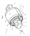
- FIG. 1 shows a preferred embodiment of the inventive bushing 1.
- a central rigid core member 3 defines a longitudinal axis z.
- the rigid core member 3 comprises basically three main portions along the longitudinal axis z.
- Two axially outer mounting portions 5, 7 each adapted to be attached to a vehicle part and an axially central bearing portion 9 which is surrounded by an elastomer body 11 and therefore basically hidden in figure 1 .
- spherical coordinates may be defined, e.g. the azimuthal angle ⁇ and the polar angle ⁇ .
- the azimuthal angle ⁇ represents a rotation about the longitudinal axis z
- a tilt in the tilting direction is represented by a rotation about an axis perpendicular to the z-axis by the polar angle ⁇ .
- the symmetry of the bushing 1 is rather cylindrical than spherical it is useful to define the radial extension with respect to the z-axis rather than to a point of origin.
- the point of origin may be defined as the axially central point of the rigid core member 3 on the longitudinal z-axis.
- the two axially outer mounting portions 5, 7 of the rigid core member 3 comprise a bore for attachment to a vehicle part (not shown). Between the mounting portions 5, 7 and the bearing portion 9 there are intermediate portions 13, 15 of less radial extension. This is important to allow for the elastomer body 11 to tilt into a tilting direction relative to the rigid core member 3 by rotating slidingly on the bearing portion 9 about the polar angle ⁇ .
- the elastomer body 9 of the preferred embodiment of the inventive bushing shown in figure 1 comprises two separate parts in form of halves 17, 19 which are mounted on the bearing portion 9.
- the halves 17, 19 of the elastomer body 11 are tightly pressed radially inward towards the bearing portion 9.
- the bushing 1 may for instance be pressed into a lug of a rod that is part of a V-stay (see figure 5 ).
- the halves 17, 19 of the elastomer body have interface portions 21, 23 each, which are mutually in contact.
- the interface portion of at least one halve 17, 19 may comprise plastically deformable studs (not shown) to provide tolerance with limited effect on the press fit. The studs will be plastically deformed during assembly dependent on the press force the halves 17, 19 are exposed to.
- the elastomer body 11 also comprises voids 25 in order to increase the flexibility of the elastomer body 11 for local compressions.
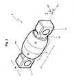
- Figure 2 gives a better perspective view on one half 17 of the elastomer body 11 of a preferred embodiment of the inventive bushing 1.
- the half 17 of the elastomer body 11 is surrounded by an outer rigid sleeve 27 stabilising the essentially half-tubular shape of the half 17 of the elastomer body 11.
- the rigid body 29 inside the elastomer body 11 may therefore be used to define a first portion 31 of the elastomer body 11 which is located radially inward from the rigid body 29 and a second portion 33 of the elastomer body 11 located radially outward from the rigid body 29.
- the radially inward first portion 31 is less voluminous than the second portion 33 to provide axial and radial stiffness.
- the second portion 33 is radially thicker that the first portion 31 but axially thinner due to axially inward concave indentations 35 at both axial ends in order to provide sufficient compressibility for rotation in a tilting direction.
- the radially outer second portion 33 comprises voids in form of axial bores through the second portion 33 to further increase the compressibility.
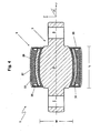
- Figure 3 illustrates a perspective view of a rigid core member 3 of a preferred embodiment of the inventive bushing 1. Especially, the axially central oval-shaped bearing portion 9 of the rigid core member 3 is visible.
- the bearing portion 9 comprises two tapering portions 37, 39 each tapering towards the axial ends of the bearing portion 9.
- the tapering is not linear but follows an oval shape such that a minimal radial extension of the bearing portion 9 is reached at the axial ends of it.
- Axially further outward the rigid core member 3 extends via two intermediate portions 13, 15 to mounting portions 5, 7.
- the intermediate portions 13, 15 have a smaller radial extension than the minimal radial extension of the bearing portion 9 in order to allow sufficient play for movement of the elastomer body 11 into a tilting direction.
- the shape of the bearing portion 9 is not spherical but essentially oval.
- the axial extension of the bearing portion i.e. its length, is larger than its maximal radial extension with respect to the longitudinal axis, i.e. its width. This ensures a central neutral position of the bearing with respect to a tilt into a tilting direction.
- one or more portions of the radially outer surface of the bearing portion 9 which are in contact with the elastomer body 11 act as return portions pressing the elastomer body 11 back to the central neutral position when the elastomer body 11 is tilted about a polar angle ⁇ relative to the rigid core member.
- the cross-sectional view of a preferred embodiment of the inventive bushing 1 shown in figure 4 gives a better impression of rigid and elastic material in the bushing 1.
- the elastomer body 11 is mounted on the essentially oval-shaped bearing portion 9 of the rigid core member 3.
- Those portions displayed chequered are of flexible, elastic and compressible elastomer material.
- Hatched portions in figure 4 display rigid material, preferably a stiff metal or an inelastic polymer.
- the shape of the radially inner surface of the rigid body 29 moulded into the elastomer body 11 is formed essentially the same way in which the radially outer surface of the bearing portion is formed.
- press-jaws may press-fit the inner rigid body 29 radially inwards towards the bearing portion 9 such that the radially inner surface of the rigid body 29 takes the form of the radially outer surface of the bearing portion 3.
- the radially inner surface of the elastomer body 11 is formed to be in sliding contact with the radially outward surface of the bearing portion 9 over the full length.
- the press-fitting ensures a radial and axial stiffness such that an overall axial displacement of the elastomer body 11 is prevented but a tilt in the tilting direction is allowed.
- Fig. 5 shows a perspective view of a decoupled V-stay assembly using four bushings according to a preferred embodiment of the invention for suspension.
- Two reaction rods 41, 43 are each attached independently in a V-configuration to a common assembly plate 45 via a bushing 1.
- the reaction rods 41, 43 comprise lugs 47 at one end into which bushings 1 are pressed.
- the assembly plate 45 comprises yoke portions 49, 51 to which the mounting portions 5, 7 of the rigid core member 3 of the bushings 1 are attached.
- the free ends of the reaction rods 41, 43 also comprise lugs 53 into which bushings 1 are pressed.
- the mounting portions 5, 7 of the rigid core member 3 of these bushings 1 may be attached to other parts of the vehicle.
Landscapes
- Engineering & Computer Science (AREA)
- Mechanical Engineering (AREA)
- General Engineering & Computer Science (AREA)
- Springs (AREA)
- Vehicle Body Suspensions (AREA)
Description
- The present invention refers to a reaction rod arrangement, in particular a V-stay suspension, for a vehicle including a bushing, wherein the bushing comprises a rigid core member having a bearing portion and defining a longitudinal axis, and an elastomer body being arranged on at least a portion of the radially outer surface of the bearing portion.
- A reaction rod arrangement such as a V-stay suspension may be used in vehicles for the connection between the vehicle frame and the axle for wheel suspension. Especially heavy vehicles such as trucks may comprise a V-stay which is connected with two end-points to the chassis and one central suspension point to the axle for wheel suspension. Such a system is for example described in
WO 2005/080101 A1 . - The V-stay suspension described in
WO 2005/080101 A1 comprises a bushing for force absorption. The suspension is exposed to movements in both rotational and tilting directions, such that the V-stay requires to be flexibly deflectable into rotational and tilting directions in order to absorb relative movements and forces between the chassis and the axle for wheel suspension. On the other hand, the V-stay needs to be stiff in other directions to provide stability. To comply with these requirements the suspension bushing described inWO 2005/080101 A1 comprises a specific design of an inclined ball joint. - Another solution for a suspension bushing is presented in
EP 0 226 702 A1 - The
EP 0 226 702 A1 - This solution has the disadvantage that the bushing is costly and too stiff in tilting directions. The reason for this is that radial stiffness is provided by a relatively thin inner elastomer body which is able to rotate about the longitudinal axis only. The elasticity in the tilting directions is provided by the more voluminous outer elastomer body which is fixed to the metallic bodies by vulcanisation. Therefore, the flexibility in the tilting directions is limited by the shear strength of the outer elastomer body. The stress on the elastomer body poses a high risk of wear and abrasion.
- Another problem is that there is a high risk of a displacement of the elastomer with respect to the inner metallic body along the longitudinal axis. In order to maintain flexibility in the tilting directions the axial ends of the bushing can not be secured by a tight flange fitting. With regard to the large forces applied the suggested axial fixation, by means of recesses and projections between the elastomer body and the inner metallic body, does not safely secure the bushing in the axial direction.
-
WO 00/51833 -
GB 2 417 054 A -
EP 1 772 357 A2 -
EP 0 698 743 A2 -
GB 1,020,799 -
DE 36 13 123 A discloses a bearing with a void in an elastomer body. The elastomer body can also rotate about the longitudinal axis of a rigid core member. A tilting movement of the elastomer body with respect to the rigid core member is not possible. - The present invention is based on
DE 38 43 820 Cl which discloses a reaction rod arrangement, in particular a V-stay suspension, for a vehicle including a bushing. The bushing comprises a rigid core member with an outer surface forming a bearing having a first and a second tapering portion. The axial extension of the oval, non-spherical bushing along the longitudinal axis of the bushing portion is larger than its maximal radial extension. On the radial outer surface of the bearing an elastomer body is arranged. The elastomer body further comprises a rigid body moulded into the elastomer. - It is therefore the object of the present invention to provide a simpler and more inexpensive reaction rod arrangement including a bushing such that the suspension is stiff and secured in the radial and axial directions and flexible in the tilting directions.
- This object is solved by the subject-matter of
claim 1. Preferred embodiments of the invention are subject of the dependent claims 2 to 8. - According to the present invention a reaction rod arrangement, in particular a V-stay suspension, for a vehicle including a bushing is provided, wherein the bushing comprises a rigid core member having a bearing portion and defining a longitudinal axis, and an elastomer body being arranged on at least a portion of the radially outer surface of the bearing portion of the rigid core member, characterised in that the bearing portion comprises a first and a second tapering portion, wherein the first tapering portion tapers towards one axial end of the bearing portion and the second tapering portion tapers towards the other opposite axial end of the bearing portion, wherein the axial extension of the bearing portion is larger than its radial extension, and wherein the elastomer body is movably arranged on the bearing portion such that the elastomer body is able to perform a rotational movement about the longitudinal axis relative to the rigid core member and able to perform a tilting movement about an axis perpendicular to the longitudinal axis relative to the rigid core member.
- The rigid core member typically comprises three portions along the longitudinal axis. Two axially outer mounting portions each adapted to be attached to a vehicle part and an axially central bearing portion which is constructed essentially rotational-symmetric about the longitudinal axis. Herein, "axial" means along the longitudinal axis of the rigid core member. Contrary, "radial" refers to a direction perpendicular to the longitudinal axis of the rigid core member. Further, the term "tapering" means herein any way of reducing in radial extension along an axial path. "Tapering" or "taper" is therefore not restricted to a conical shape which reduces linearly in radial extension along the axial direction but includes any non-linear reduction of radial extension complying with the requirement that the axial extension of the bearing portion is larger than its maximal radial extension with respect to the longitudinal axis. A tilting movement about an axis perpendicular to the longitudinal axis relative to the rigid core member represents a rotation into a tilting direction.
- A rigid body is moulded into the elastomer body and the elastomer body comprises voids. A first portion of the elastomer body is located radially inward from the rigid body and is less voluminous than a second portion of the elastomer body located radially outward from the rigid body. A void in the elastomer body is located radially outward from the rigid body.
- Preferably, the bearing portion of the rigid core member has at least partially an oval, non-spherical shape. The length of the bearing portion represents its axial extension along the longitudinal axis. The width of the bearing portion is defined by its maximal radial extension with respect to the longitudinal axis. The fact that the length of the bearing portion is larger than the width of the bearing portion ensures that the shape of the bearing portion is non-spherical. This has the advantage that a central neutral position is defined with respect to a tilting direction. A tilt in a tilting direction leads to a slight return force induced by a local compression of the elastomer body pressing the bushing back to a central neutral position. If the bushing would remain in a tilted position, as it would be the case for a ball-joint configuration known for instance from
WO 2005/080101 A1 , there is a risk that parts of the V-stay accidentally contact other parts of the vehicle. Especially when the bushing is unstressed during manufacturing, assembling, maintenance, inspection or repair of the vehicle it is advantageous that the bushing takes a central neutral position all by itself. Therefore, it is preferred that said portion of the radially outer surface of the bearing portion of the rigid core member comprises at least one return portion arranged to press the elastomer body back to a neutral position relative to the rigid core when the elastomer body is tilted about an axis perpendicular to the longitudinal axis relative to the rigid core member. - It is an important feature of the invention that the elastomer body is movable relative to the bearing portion in a tilting direction, i.e. about an axis perpendicular to the longitudinal axis by a polar angle relative to the rigid core member. This mobility is in addition to a rotational mobility around the longitudinal axis relative to the rigid core member. It should, however, be noted that the elastomer body is tightly fitted to the bearing portion in such a way that in case of forces in a tilting direction the elastomer body first deforms locally before it starts sliding relative to the bearing portion in a tilting direction. This is due to the frictional force between the elastomer body and the bearing portion. In a bearing portion of spherical shape as it is for instance present in a ball joint configuration, a force acting on the elastomer body in a tilting direction is directed tangentially with respect to the contact surface, i.e. parallel to the frictional resistance without a radial vector component causing local deformations of the elastomer body. In contrast to that, the tapering or oval shape of the bearing portion of the inventive bushing results in a stronger frictional contact between the elastomer body and the bearing portion. A force acting on the elastomer body in a tilting direction is directed with an angle to the return surface of the bearing portion, i.e. a radial vector component causes local deformations of the elastomer body which increases the normal force between elastomer body and the bearing portion. Only when the tangential component of a force acting on the elastomer body in a tilting direction is large enough to overcome the frictional resistance between the elastomer body and the bearing portion the elastomer body starts to slide in a tilting direction relative to the bearing portion. Therefore, the elastomer body of the inventive bearing does not slide in case of small tilting forces. Small tilting movements are absorbed by local deformations of the elastomer body. If the forces exceed a certain threshold the elastomer body starts sliding relative to the bearing portion in a tilting direction.
- Due to the tapering shape of the bearing portion an axial displacement of the elastomer body is prevented, whereas a tilt in a tilting direction is allowed. Compared to the solution known from
EP 0 226 702 A1 - In a preferred embodiment of the inventive bushing the elastomer body comprises two separate parts which are mounted on the rigid core. The parts of the elastomer body may be pressed towards the rigid core by surrounding material the bushing is pressed into. Preferably, the parts of the elastomer body are halves with interface portions each, wherein the respective interface portions of the halves are in contact with each other when the bushing is mounted.
- This embodiment has the advantage that there is no complicated fixation by vulcanisation needed to provide a safely secured elastic suspension. The production and mounting costs are comparatively low. In addition, the interface portion of at least one halve may comprise plastically deformable studs to provide tolerance with limited effect on the press fit. The studs will be plastically deformed during assembly dependent on the press force the halves are exposed to.
- It may be advantageous that the elastomer body comprises voids in order to increase the flexibility of the elastomer body for local compressions. Furthermore, it may be preferred that a rigid body is moulded into the elastomer body in order to increase radial and axial stiffness. The radially inner surface of the rigid body may be formed essentially the same way in which said portion of the radially outer surface of the bearing portion is formed. The rigid body increases the inner stability of the bushing and secures the elastomer body to the bearing portion of the rigid core member in radial and axial direction. In order to further maximise radial and axial stiffness it is advantageous if a first portion of the elastomer body is located radially inward from the rigid body and is less voluminous than a second portion of the elastomer body located radially outward from the rigid body. The radially inner first portion is therefore less compressible than the radially outer second portion. The compression of the elastomer body due to a tilt in a tilting direction may therefore be essentially performed in the radially outer second portion. In case the elastomer body comprises voids, these should be located radially outward from the rigid body.
- In the following the present invention is discussed in further detail with reference to the accompanying
figures 1 to 5 displaying a preferred embodiment of the invention. -
Fig. 1 shows a perspective view of a preferred embodiment of the inventive bushing before it is pressed into a receptacle part of the vehicle. -
Fig. 2 shows a perspective view of one half of an elastomer body of a preferred embodiment of the inventive bushing. -
Fig. 3 illustrates a perspective view of a rigid core member of a preferred embodiment of the inventive bushing. -
Fig. 4 shows a cross-sectional view of a preferred embodiment of the inventive bushing. -
Fig. 5 shows a perspective view of a decoupled V-stay assembly using bushings according to a preferred embodiment of the invention for suspension. - The perspective view of
figure 1 shows a preferred embodiment of theinventive bushing 1. A centralrigid core member 3 defines a longitudinal axis z. Therigid core member 3 comprises basically three main portions along the longitudinal axis z. Two axially outer mountingportions central bearing portion 9 which is surrounded by anelastomer body 11 and therefore basically hidden infigure 1 . - To clarify the different directions of motion it is useful to define a coordinate system as shown in
figure 1 . Starting from a cartesian coordinate system with a z-axis corresponding to the longitudinal axis of therigid core member 3 and a cross-sectional plane spanned by the perpendicular axes x and y, spherical coordinates may be defined, e.g. the azimuthal angle φ and the polar angle θ. The azimuthal angle φ represents a rotation about the longitudinal axis z, whereas a tilt in the tilting direction is represented by a rotation about an axis perpendicular to the z-axis by the polar angle θ. As the symmetry of thebushing 1 is rather cylindrical than spherical it is useful to define the radial extension with respect to the z-axis rather than to a point of origin. The point of origin, however, may be defined as the axially central point of therigid core member 3 on the longitudinal z-axis. - The two axially outer mounting
portions rigid core member 3 comprise a bore for attachment to a vehicle part (not shown). Between the mountingportions portion 9 there areintermediate portions elastomer body 11 to tilt into a tilting direction relative to therigid core member 3 by rotating slidingly on the bearingportion 9 about the polar angle θ. - The
elastomer body 9 of the preferred embodiment of the inventive bushing shown infigure 1 comprises two separate parts in form ofhalves portion 9. Thehalves elastomer body 11 are tightly pressed radially inward towards the bearingportion 9. For the sake of visibility the surrounding material the bushing is pressed into is not shown. Thebushing 1 may for instance be pressed into a lug of a rod that is part of a V-stay (seefigure 5 ). Thehalves interface portions halve halves - The
elastomer body 11 also comprisesvoids 25 in order to increase the flexibility of theelastomer body 11 for local compressions.Figure 2 gives a better perspective view on onehalf 17 of theelastomer body 11 of a preferred embodiment of theinventive bushing 1. Thehalf 17 of theelastomer body 11 is surrounded by an outerrigid sleeve 27 stabilising the essentially half-tubular shape of thehalf 17 of theelastomer body 11. There is arigid body 29 moulded into theelastomer body 11. Thisrigid body 29 provides radial and axial stiffness for theelastomer body 11 as it extends almost over the full length of theelastomer body 11. Therigid body 29 inside theelastomer body 11 may therefore be used to define afirst portion 31 of theelastomer body 11 which is located radially inward from therigid body 29 and asecond portion 33 of theelastomer body 11 located radially outward from therigid body 29. The radially inwardfirst portion 31 is less voluminous than thesecond portion 33 to provide axial and radial stiffness. Thesecond portion 33 is radially thicker that thefirst portion 31 but axially thinner due to axially inwardconcave indentations 35 at both axial ends in order to provide sufficient compressibility for rotation in a tilting direction. In addition to that the radially outersecond portion 33 comprises voids in form of axial bores through thesecond portion 33 to further increase the compressibility. -
Figure 3 illustrates a perspective view of arigid core member 3 of a preferred embodiment of theinventive bushing 1. Especially, the axially central oval-shapedbearing portion 9 of therigid core member 3 is visible. The bearingportion 9 comprises two taperingportions portion 9. The tapering is not linear but follows an oval shape such that a minimal radial extension of the bearingportion 9 is reached at the axial ends of it. Axially further outward therigid core member 3 extends via twointermediate portions portions intermediate portions portion 9 in order to allow sufficient play for movement of theelastomer body 11 into a tilting direction. It is important to note that the shape of the bearingportion 9 is not spherical but essentially oval. The axial extension of the bearing portion, i.e. its length, is larger than its maximal radial extension with respect to the longitudinal axis, i.e. its width. This ensures a central neutral position of the bearing with respect to a tilt into a tilting direction. Depending on the tilt direction one or more portions of the radially outer surface of the bearingportion 9 which are in contact with theelastomer body 11 act as return portions pressing theelastomer body 11 back to the central neutral position when theelastomer body 11 is tilted about a polar angle θ relative to the rigid core member. This pressing force results in a local compression of theelastomer body 11 such that a return force inducing a turning moment towards the central neutral position is induced. Due to the large forces a V-stay is exposed to during operation of the vehicle this return force does not significantly limit the flexibility for the movement into a tilting direction. On the other hand, when the V-stay and therefore thebushing 1 is essentially unstressed during manufacturing, assembling, maintenance, inspection or repair of the vehicle for instance by jacking up the vehicle it is advantageous that thebushing 1 takes a central neutral position all by itself. - The cross-sectional view of a preferred embodiment of the
inventive bushing 1 shown infigure 4 gives a better impression of rigid and elastic material in thebushing 1. Theelastomer body 11 is mounted on the essentially oval-shapedbearing portion 9 of therigid core member 3. Those portions displayed chequered are of flexible, elastic and compressible elastomer material. Hatched portions infigure 4 display rigid material, preferably a stiff metal or an inelastic polymer. The shape of the radially inner surface of therigid body 29 moulded into theelastomer body 11 is formed essentially the same way in which the radially outer surface of the bearing portion is formed. - From
Figure 4 the easy and inexpensive way for manufacturing thebushing 1 may be appreciated. Before assembling theelastomer body 11 on the bearingportion 9 theelastomer body 11 together with the innerrigid body 3 and the radiallyouter sleeve 27 may have a tubular shape with a constant inner radius over its length. Therefore, theelastomer body 11 may be imposed on the bearingportion 9. When theelastomer body 11 is located at the axially central position, press-jaws of an assembly unit (not shown) may engage with the axially inwardconcave indentations 35 at both axial ends of theelastomer body 11. These press-jaws may press-fit the innerrigid body 29 radially inwards towards the bearingportion 9 such that the radially inner surface of therigid body 29 takes the form of the radially outer surface of the bearingportion 3. Thereby, the radially inner surface of theelastomer body 11 is formed to be in sliding contact with the radially outward surface of the bearingportion 9 over the full length. The press-fitting ensures a radial and axial stiffness such that an overall axial displacement of theelastomer body 11 is prevented but a tilt in the tilting direction is allowed. -
Fig. 5 shows a perspective view of a decoupled V-stay assembly using four bushings according to a preferred embodiment of the invention for suspension. Tworeaction rods common assembly plate 45 via abushing 1. Thereaction rods lugs 47 at one end into whichbushings 1 are pressed. Theassembly plate 45 comprisesyoke portions portions rigid core member 3 of thebushings 1 are attached. The free ends of thereaction rods bushings 1 are pressed. The mountingportions rigid core member 3 of thesebushings 1 may be attached to other parts of the vehicle.
Claims (8)
- A reaction rod arrangement, in particular a V-stay suspension, for a vehicle including a bushing (1), wherein the bushing (1) comprises
a rigid core member (3) having a bearing portion (9) and defining a longitudinal axis (z), and
an elastomer body (11) being arranged on at least a portion of the radially outer surface of the bearing portion (9),
wherein the bearing portion (9) comprises a first and a second tapering portion (37, 39), wherein the first tapering portion (37) tapers towards one axial end of the bearing portion (9) and the second tapering portion (39) tapers towards the other opposite axial end of the bearing portion (9),
wherein the axial extension of the bearing portion (9) is larger than its maximal radial extension with respect to the longitudinal axis (z),
wherein the elastomer body (11) is movably arranged on the bearing portion (9) such that the elastomer body (11) is able to perform a rotational movement about the longitudinal axis (z) relative to the rigid core member (3) and a tilting movement about an axis perpendicular to the longitudinal axis (z) relative to the rigid core member (3) and
wherein a rigid body (29) is moulded into the elastomer body (11),
characterized in
that a first portion (31) of the elastomer body (11) is located radially inward from the rigid body (29) and is less voluminous than a second portion (33) of the elastomer body (11) located radially outward from the rigid body (29) and
that the elastomer body (11) comprises voids (25), wherein a void (25) in the elastomer body (11) is located radially outward from the rigid body (29). - A reaction rod arrangement according to claim 1, wherein the bearing portion (9) has at least partially an oval, non-spherical shape.
- A reaction rod arrangement according to claim 1 or 2, wherein said portion of the radially outer surface of the bearing portion (9) comprises at least one return portion arranged to press the elastomer body (11) back to a neutral position relative to the rigid core member (3) when the elastomer body (11) is tilted about an axis perpendicular to the longitudinal axis (z) relative to the rigid core member (3).
- A reaction rod arrangement according to any one of the preceding claims, wherein the elastomer body (11) comprises two separate parts (17, 19) which are mounted on the rigid core member (3).
- A reaction rod arrangement according to claim 4, wherein the parts (17, 19) of the elastomer body (11) are pressed towards the rigid core member (3) by surrounding material the bushing (1) is pressed into.
- A reaction rod arrangement according to claim 4 or 5, wherein the parts (17, 19) of the elastomer body (11) are halves (17, 19) with interface portions (21, 23) each, wherein the respective interface portions (21, 23) of the halves (17, 19) are in contact with each other when the bushing (1) is mounted.
- A reaction rod arrangement according to claim 6, wherein the interface portion (21, 23) of at least one halve (17, 19) comprises plastically deformable studs.
- A reaction rod arrangement according to any of the previous claims, wherein the radially inner surface of the rigid body (29) is formed essentially the same way in which said portion of the radially outer surface of the bearing portion (9) is formed.
Applications Claiming Priority (1)
| Application Number | Priority Date | Filing Date | Title |
|---|---|---|---|
| PCT/IB2008/000847 WO2009125238A1 (en) | 2008-04-07 | 2008-04-07 | Reaction rod arrangement |
Publications (3)
| Publication Number | Publication Date |
|---|---|
| EP2259935A1 EP2259935A1 (en) | 2010-12-15 |
| EP2259935A4 EP2259935A4 (en) | 2012-03-21 |
| EP2259935B1 true EP2259935B1 (en) | 2014-01-22 |
Family
ID=41161584
Family Applications (1)
| Application Number | Title | Priority Date | Filing Date |
|---|---|---|---|
| EP08719433.8A Active EP2259935B1 (en) | 2008-04-07 | 2008-04-07 | Reaction rod arrangement |
Country Status (6)
| Country | Link |
|---|---|
| US (1) | US20110026862A1 (en) |
| EP (1) | EP2259935B1 (en) |
| KR (1) | KR101442311B1 (en) |
| CN (1) | CN101990504B (en) |
| BR (1) | BRPI0822571A2 (en) |
| WO (1) | WO2009125238A1 (en) |
Cited By (3)
| Publication number | Priority date | Publication date | Assignee | Title |
|---|---|---|---|---|
| DE102014112181A1 (en) | 2014-08-26 | 2016-03-03 | Bhc Gummi-Metall Gmbh | Elastic joint for a vehicle handlebar arm |
| EP4119368A1 (en) | 2021-07-15 | 2023-01-18 | Bhc Gummi-Metall Gmbh | Pivot bearing for supporting a vehicle steering arm |
| EP4145007A1 (en) | 2021-09-03 | 2023-03-08 | Bhc Gummi-Metall Gmbh | Elastic joint for a vehicle steering arm |
Families Citing this family (21)
| Publication number | Priority date | Publication date | Assignee | Title |
|---|---|---|---|---|
| US8579510B2 (en) * | 2010-03-12 | 2013-11-12 | Hendrickson Usa, L.L.C. | Rotatable bar pin bushing assembly |
| WO2013026022A1 (en) * | 2011-08-18 | 2013-02-21 | Caterpillar Inc. | Elastomeric bearing for equalizer bar of undercarriage |
| DE102012010111A1 (en) * | 2012-05-22 | 2013-11-28 | SGF SüDDEUTSCHE GELENKSCHEIBENFABRIK GMBH & CO. KG | Damping bearing device for mounting two components to each other |
| JP6190638B2 (en) * | 2013-06-27 | 2017-08-30 | 住友理工株式会社 | Anti-vibration bush and method for manufacturing anti-vibration bush |
| EP3110638B1 (en) | 2014-02-26 | 2019-04-03 | Sampa Otomotiv Sanayi Ve Ticaret Anonim Sirketi | A connecting arm with a bushing |
| GB201416532D0 (en) * | 2014-09-18 | 2014-11-05 | Subsea Riser Products Ltd | Bearing assembly for an axially loaded member |
| US20160159182A1 (en) * | 2014-12-03 | 2016-06-09 | The Pullman Company | Multi-piece bar pin for elastomeric bushing assembly |
| US10767721B2 (en) | 2015-08-18 | 2020-09-08 | Hendrickson Usa, L.L.C. | Bar pin bushing for vehicle suspension |
| US10704637B2 (en) * | 2015-08-18 | 2020-07-07 | Hendrickson Usa, L.L.C. | Bar pin bushing for vehicle suspension |
| EP3255289B1 (en) | 2016-06-09 | 2020-12-09 | Claverham Limited | Relief slot for a load bearing assembly |
| DE102016225127A1 (en) * | 2016-12-15 | 2018-06-21 | Zf Friedrichshafen Ag | Joint for a vehicle and method of manufacturing such a joint |
| JP6783135B2 (en) * | 2016-12-21 | 2020-11-11 | 住友理工株式会社 | Cylindrical anti-vibration device |
| US11209065B2 (en) | 2017-08-09 | 2021-12-28 | Vibracoustic Usa, Inc. | Low torsion bushing and assembly |
| CN109185331B (en) * | 2018-10-08 | 2020-12-15 | 株洲时代瑞唯减振装备有限公司 | Shock absorption method and structure of spherical hinge for wheel-axle-free bogie |
| CN110293803B (en) * | 2019-05-20 | 2021-06-15 | 浙江吉利控股集团有限公司 | A torsion beam bushing |
| NL2024128B1 (en) * | 2019-10-31 | 2021-07-19 | Vmi Holland Bv | Stitching roller for stitching a strip |
| CN110877508A (en) * | 2019-11-28 | 2020-03-13 | 重庆长安汽车股份有限公司 | Automotive suspension bush and suspension |
| EP3848607A3 (en) * | 2019-12-19 | 2021-12-08 | Schaublin SA | Elastomeric bearing for a suspension assembly |
| DE102020210971A1 (en) * | 2020-08-31 | 2022-03-03 | Zf Friedrichshafen Ag | connecting bridge device |
| CN112879417A (en) * | 2021-01-29 | 2021-06-01 | 中国重汽集团济南动力有限公司 | Ball joint and thrust rod assembly with adjustable rigidity |
| CN115949670B (en) * | 2023-03-09 | 2023-06-30 | 中国航发四川燃气涡轮研究院 | Elastic structure for axial compression of bearing |
Family Cites Families (29)
| Publication number | Priority date | Publication date | Assignee | Title |
|---|---|---|---|---|
| GB1020799A (en) * | 1963-05-10 | 1966-02-23 | Riv Officine Di Villar Perosa | Resilient joint for interconnecting machine parts generally |
| US3790195A (en) | 1972-06-27 | 1974-02-05 | Trw Inc | Socket joint |
| US4007924A (en) * | 1975-06-27 | 1977-02-15 | Raoul Jorn | Elastic support mount |
| DE3346665A1 (en) * | 1983-12-23 | 1985-07-04 | Lemförder Metallwaren AG, 2844 Lemförde | ELASTIC BEARING WITH FORCED GUIDE |
| DE3613123A1 (en) | 1986-04-18 | 1987-10-29 | Lemfoerder Metallwaren Ag | Elastic pivot-slide bearing for chassis parts in motor vehicles |
| DE3933163A1 (en) * | 1988-10-27 | 1990-05-03 | Toyoda Gosei Kk | CYLINDRICAL DAMPING BUSH |
| DE3843820C1 (en) * | 1988-12-24 | 1990-05-23 | Krupp Brueninghaus Gmbh, 5980 Werdohl, De | Wishbone for axles of commercial vehicles |
| US5033722A (en) * | 1989-08-21 | 1991-07-23 | Caterpillar Inc. | Resilient mount assembly |
| US5122011A (en) * | 1990-11-21 | 1992-06-16 | Pullman Company | Elastomeric bushing assembly for torque rod |
| JPH04349012A (en) * | 1991-05-24 | 1992-12-03 | Nippon Mektron Ltd | Support bushing for stabilizer |
| JP3384575B2 (en) * | 1992-10-20 | 2003-03-10 | 東洋ゴム工業株式会社 | Sliding bush |
| CA2108983A1 (en) * | 1992-11-10 | 1994-05-11 | Robert L. Carper | Bushing for an automobile suspension system |
| DE4316213A1 (en) * | 1993-05-14 | 1994-11-17 | Porsche Ag | Universal swivel bearing |
| DE4430037C2 (en) * | 1994-08-24 | 1996-12-12 | Metzeler Gimetall Ag | Bearing bush |
| NL1002490C2 (en) * | 1996-02-29 | 1997-09-01 | Netherlands Car Bv | Motor vehicle. |
| US6231264B1 (en) * | 1998-11-12 | 2001-05-15 | The Pullman Company | Torque rod bearing assembly |
| GB2345476B (en) * | 1999-01-08 | 2002-07-31 | Rover Group | Vehicle suspensions |
| JP2002538047A (en) * | 1999-03-02 | 2002-11-12 | ツェットエフ レムフェルダー メタルヴァーレン アクチエンゲゼルシャフト | Axle suspension of rigid axle |
| DE10011124C2 (en) * | 2000-03-09 | 2002-10-31 | Zf Lemfoerder Metallwaren Ag | Rubber bearing |
| DE10204975B4 (en) * | 2001-02-12 | 2006-05-11 | The Pullman Co., Milan | swivel |
| DE10118623A1 (en) * | 2001-05-18 | 2002-12-05 | Zf Lemfoerder Metallwaren Ag | axle rocker |
| NO315192B1 (en) * | 2002-03-12 | 2003-07-28 | Kongsberg Automotive Asa | coupling |
| US20040108640A1 (en) * | 2002-12-09 | 2004-06-10 | Michael Robert Joseph | Elastomeric bearing assembly and associated pin structure |
| DE10258986B4 (en) * | 2002-12-16 | 2005-07-14 | ZF Lemförder Metallwaren AG | Elastic chassis bearing for commercial vehicles |
| DE10362009B4 (en) * | 2003-09-09 | 2009-04-09 | ZF Lemförder GmbH | ball joint |
| GB2417054B (en) * | 2004-08-12 | 2006-06-28 | Minebea Co Ltd | A resilient bush |
| ATE509791T1 (en) * | 2004-11-26 | 2011-06-15 | Volvo Lastvagnar Ab | FASTENING SYSTEM FOR A V-BRACE IN A LARGE VEHICLE |
| US7644911B2 (en) * | 2005-09-22 | 2010-01-12 | The Pullman Company | Isolator |
| US8037573B2 (en) * | 2008-04-03 | 2011-10-18 | The Pullman Company | Curled bushing with torsional slip |
-
2008
- 2008-04-07 CN CN2008801284200A patent/CN101990504B/en active Active
- 2008-04-07 WO PCT/IB2008/000847 patent/WO2009125238A1/en not_active Ceased
- 2008-04-07 BR BRPI0822571A patent/BRPI0822571A2/en not_active IP Right Cessation
- 2008-04-07 EP EP08719433.8A patent/EP2259935B1/en active Active
- 2008-04-07 KR KR1020107023009A patent/KR101442311B1/en active Active
- 2008-04-07 US US12/936,731 patent/US20110026862A1/en not_active Abandoned
Cited By (5)
| Publication number | Priority date | Publication date | Assignee | Title |
|---|---|---|---|---|
| DE102014112181A1 (en) | 2014-08-26 | 2016-03-03 | Bhc Gummi-Metall Gmbh | Elastic joint for a vehicle handlebar arm |
| EP4119368A1 (en) | 2021-07-15 | 2023-01-18 | Bhc Gummi-Metall Gmbh | Pivot bearing for supporting a vehicle steering arm |
| DE102021118344A1 (en) | 2021-07-15 | 2023-01-19 | Bhc Gummi-Metall Gmbh | Pivoting bearing for supporting a vehicle control arm |
| EP4145007A1 (en) | 2021-09-03 | 2023-03-08 | Bhc Gummi-Metall Gmbh | Elastic joint for a vehicle steering arm |
| DE102021122875A1 (en) | 2021-09-03 | 2023-03-09 | Bhc Gummi-Metall Gmbh | Elastic joint for a vehicle control arm |
Also Published As
| Publication number | Publication date |
|---|---|
| KR101442311B1 (en) | 2014-11-03 |
| EP2259935A1 (en) | 2010-12-15 |
| CN101990504A (en) | 2011-03-23 |
| KR20100134041A (en) | 2010-12-22 |
| CN101990504B (en) | 2013-04-10 |
| WO2009125238A1 (en) | 2009-10-15 |
| BRPI0822571A2 (en) | 2015-10-13 |
| EP2259935A4 (en) | 2012-03-21 |
| US20110026862A1 (en) | 2011-02-03 |
Similar Documents
| Publication | Publication Date | Title |
|---|---|---|
| EP2259935B1 (en) | Reaction rod arrangement | |
| RU2570983C2 (en) | Vehicle and spherical joint for vehicle front suspension | |
| US6959935B2 (en) | Steering triangle | |
| JP5413993B2 (en) | Connecting vehicle joint | |
| US8647010B2 (en) | Joint and/or bearing assembly having an elastic intermediate layer | |
| US20110033230A1 (en) | Joint and/or bearing arrangement | |
| US6511084B1 (en) | Axle suspension of rigid axles | |
| JPH06137317A (en) | Turning bearing device | |
| EP1772346A1 (en) | Slip joint for use in steering system | |
| US8726465B2 (en) | Hinge assembly | |
| WO2003064877A1 (en) | Cross coupling | |
| US20180178607A1 (en) | Joint connection and arrangement for mounting a wheel | |
| CN204197022U (en) | A kind of overall steering swivel and corresponding Control arm | |
| CN102145709A (en) | Rack bar supporting device of steering apparatus for vehicle | |
| US3537737A (en) | Joint assemblage for use in suspension systems of motor vehicles | |
| CN103204040B (en) | Rear wheel suspension system | |
| JPWO2019031396A1 (en) | Bearings and suspensions | |
| JP6223052B2 (en) | Damper mounting device | |
| CN101618668B (en) | Automobile track bar connector | |
| CN219284320U (en) | Sensor and automobile using same | |
| CN201443559U (en) | Automobile thrust rod joint | |
| CN222512246U (en) | Steering system for vehicle | |
| CN1892057A (en) | Automobile thrust rod joint | |
| CN2656179Y (en) | A car thrust rod joint | |
| CN217977025U (en) | Maintenance-free ball joint assembly |
Legal Events
| Date | Code | Title | Description |
|---|---|---|---|
| PUAI | Public reference made under article 153(3) epc to a published international application that has entered the european phase |
Free format text: ORIGINAL CODE: 0009012 |
|
| 17P | Request for examination filed |
Effective date: 20100915 |
|
| AK | Designated contracting states |
Kind code of ref document: A1 Designated state(s): AT BE BG CH CY CZ DE DK EE ES FI FR GB GR HR HU IE IS IT LI LT LU LV MC MT NL NO PL PT RO SE SI SK TR |
|
| AX | Request for extension of the european patent |
Extension state: AL BA MK RS |
|
| DAX | Request for extension of the european patent (deleted) | ||
| A4 | Supplementary search report drawn up and despatched |
Effective date: 20120222 |
|
| RIC1 | Information provided on ipc code assigned before grant |
Ipc: F16C 11/06 20060101ALI20120216BHEP Ipc: B60G 7/00 20060101AFI20120216BHEP Ipc: B60G 9/00 20060101ALI20120216BHEP Ipc: F16C 27/06 20060101ALI20120216BHEP |
|
| 17Q | First examination report despatched |
Effective date: 20121214 |
|
| GRAP | Despatch of communication of intention to grant a patent |
Free format text: ORIGINAL CODE: EPIDOSNIGR1 |
|
| INTG | Intention to grant announced |
Effective date: 20130920 |
|
| GRAS | Grant fee paid |
Free format text: ORIGINAL CODE: EPIDOSNIGR3 |
|
| GRAA | (expected) grant |
Free format text: ORIGINAL CODE: 0009210 |
|
| AK | Designated contracting states |
Kind code of ref document: B1 Designated state(s): AT BE BG CH CY CZ DE DK EE ES FI FR GB GR HR HU IE IS IT LI LT LU LV MC MT NL NO PL PT RO SE SI SK TR |
|
| REG | Reference to a national code |
Ref country code: GB Ref legal event code: FG4D |
|
| REG | Reference to a national code |
Ref country code: SE Ref legal event code: TRGR |
|
| REG | Reference to a national code |
Ref country code: CH Ref legal event code: EP |
|
| REG | Reference to a national code |
Ref country code: AT Ref legal event code: REF Ref document number: 650608 Country of ref document: AT Kind code of ref document: T Effective date: 20140215 |
|
| REG | Reference to a national code |
Ref country code: IE Ref legal event code: FG4D |
|
| REG | Reference to a national code |
Ref country code: DE Ref legal event code: R096 Ref document number: 602008030070 Country of ref document: DE Effective date: 20140306 |
|
| REG | Reference to a national code |
Ref country code: NL Ref legal event code: VDEP Effective date: 20140122 |
|
| REG | Reference to a national code |
Ref country code: AT Ref legal event code: MK05 Ref document number: 650608 Country of ref document: AT Kind code of ref document: T Effective date: 20140122 |
|
| REG | Reference to a national code |
Ref country code: LT Ref legal event code: MG4D |
|
| PG25 | Lapsed in a contracting state [announced via postgrant information from national office to epo] |
Ref country code: NO Free format text: LAPSE BECAUSE OF FAILURE TO SUBMIT A TRANSLATION OF THE DESCRIPTION OR TO PAY THE FEE WITHIN THE PRESCRIBED TIME-LIMIT Effective date: 20140422 Ref country code: IS Free format text: LAPSE BECAUSE OF FAILURE TO SUBMIT A TRANSLATION OF THE DESCRIPTION OR TO PAY THE FEE WITHIN THE PRESCRIBED TIME-LIMIT Effective date: 20140522 Ref country code: LT Free format text: LAPSE BECAUSE OF FAILURE TO SUBMIT A TRANSLATION OF THE DESCRIPTION OR TO PAY THE FEE WITHIN THE PRESCRIBED TIME-LIMIT Effective date: 20140122 |
|
| PG25 | Lapsed in a contracting state [announced via postgrant information from national office to epo] |
Ref country code: NL Free format text: LAPSE BECAUSE OF FAILURE TO SUBMIT A TRANSLATION OF THE DESCRIPTION OR TO PAY THE FEE WITHIN THE PRESCRIBED TIME-LIMIT Effective date: 20140122 Ref country code: AT Free format text: LAPSE BECAUSE OF FAILURE TO SUBMIT A TRANSLATION OF THE DESCRIPTION OR TO PAY THE FEE WITHIN THE PRESCRIBED TIME-LIMIT Effective date: 20140122 Ref country code: ES Free format text: LAPSE BECAUSE OF FAILURE TO SUBMIT A TRANSLATION OF THE DESCRIPTION OR TO PAY THE FEE WITHIN THE PRESCRIBED TIME-LIMIT Effective date: 20140122 Ref country code: PT Free format text: LAPSE BECAUSE OF FAILURE TO SUBMIT A TRANSLATION OF THE DESCRIPTION OR TO PAY THE FEE WITHIN THE PRESCRIBED TIME-LIMIT Effective date: 20140522 Ref country code: FI Free format text: LAPSE BECAUSE OF FAILURE TO SUBMIT A TRANSLATION OF THE DESCRIPTION OR TO PAY THE FEE WITHIN THE PRESCRIBED TIME-LIMIT Effective date: 20140122 Ref country code: CY Free format text: LAPSE BECAUSE OF FAILURE TO SUBMIT A TRANSLATION OF THE DESCRIPTION OR TO PAY THE FEE WITHIN THE PRESCRIBED TIME-LIMIT Effective date: 20140122 |
|
| PG25 | Lapsed in a contracting state [announced via postgrant information from national office to epo] |
Ref country code: LV Free format text: LAPSE BECAUSE OF FAILURE TO SUBMIT A TRANSLATION OF THE DESCRIPTION OR TO PAY THE FEE WITHIN THE PRESCRIBED TIME-LIMIT Effective date: 20140122 Ref country code: HR Free format text: LAPSE BECAUSE OF FAILURE TO SUBMIT A TRANSLATION OF THE DESCRIPTION OR TO PAY THE FEE WITHIN THE PRESCRIBED TIME-LIMIT Effective date: 20140122 Ref country code: BE Free format text: LAPSE BECAUSE OF FAILURE TO SUBMIT A TRANSLATION OF THE DESCRIPTION OR TO PAY THE FEE WITHIN THE PRESCRIBED TIME-LIMIT Effective date: 20140122 |
|
| REG | Reference to a national code |
Ref country code: DE Ref legal event code: R097 Ref document number: 602008030070 Country of ref document: DE |
|
| PG25 | Lapsed in a contracting state [announced via postgrant information from national office to epo] |
Ref country code: CZ Free format text: LAPSE BECAUSE OF FAILURE TO SUBMIT A TRANSLATION OF THE DESCRIPTION OR TO PAY THE FEE WITHIN THE PRESCRIBED TIME-LIMIT Effective date: 20140122 Ref country code: DK Free format text: LAPSE BECAUSE OF FAILURE TO SUBMIT A TRANSLATION OF THE DESCRIPTION OR TO PAY THE FEE WITHIN THE PRESCRIBED TIME-LIMIT Effective date: 20140122 Ref country code: RO Free format text: LAPSE BECAUSE OF FAILURE TO SUBMIT A TRANSLATION OF THE DESCRIPTION OR TO PAY THE FEE WITHIN THE PRESCRIBED TIME-LIMIT Effective date: 20140122 Ref country code: EE Free format text: LAPSE BECAUSE OF FAILURE TO SUBMIT A TRANSLATION OF THE DESCRIPTION OR TO PAY THE FEE WITHIN THE PRESCRIBED TIME-LIMIT Effective date: 20140122 |
|
| PG25 | Lapsed in a contracting state [announced via postgrant information from national office to epo] |
Ref country code: LU Free format text: LAPSE BECAUSE OF FAILURE TO SUBMIT A TRANSLATION OF THE DESCRIPTION OR TO PAY THE FEE WITHIN THE PRESCRIBED TIME-LIMIT Effective date: 20140407 Ref country code: PL Free format text: LAPSE BECAUSE OF FAILURE TO SUBMIT A TRANSLATION OF THE DESCRIPTION OR TO PAY THE FEE WITHIN THE PRESCRIBED TIME-LIMIT Effective date: 20140122 Ref country code: SK Free format text: LAPSE BECAUSE OF FAILURE TO SUBMIT A TRANSLATION OF THE DESCRIPTION OR TO PAY THE FEE WITHIN THE PRESCRIBED TIME-LIMIT Effective date: 20140122 Ref country code: MC Free format text: LAPSE BECAUSE OF FAILURE TO SUBMIT A TRANSLATION OF THE DESCRIPTION OR TO PAY THE FEE WITHIN THE PRESCRIBED TIME-LIMIT Effective date: 20140122 |
|
| PLBE | No opposition filed within time limit |
Free format text: ORIGINAL CODE: 0009261 |
|
| REG | Reference to a national code |
Ref country code: CH Ref legal event code: PL |
|
| STAA | Information on the status of an ep patent application or granted ep patent |
Free format text: STATUS: NO OPPOSITION FILED WITHIN TIME LIMIT |
|
| GBPC | Gb: european patent ceased through non-payment of renewal fee |
Effective date: 20140422 |
|
| 26N | No opposition filed |
Effective date: 20141023 |
|
| REG | Reference to a national code |
Ref country code: FR Ref legal event code: ST Effective date: 20141231 |
|
| REG | Reference to a national code |
Ref country code: IE Ref legal event code: MM4A |
|
| PG25 | Lapsed in a contracting state [announced via postgrant information from national office to epo] |
Ref country code: CH Free format text: LAPSE BECAUSE OF NON-PAYMENT OF DUE FEES Effective date: 20140430 Ref country code: LI Free format text: LAPSE BECAUSE OF NON-PAYMENT OF DUE FEES Effective date: 20140430 Ref country code: GB Free format text: LAPSE BECAUSE OF NON-PAYMENT OF DUE FEES Effective date: 20140422 |
|
| REG | Reference to a national code |
Ref country code: DE Ref legal event code: R097 Ref document number: 602008030070 Country of ref document: DE Effective date: 20141023 |
|
| PG25 | Lapsed in a contracting state [announced via postgrant information from national office to epo] |
Ref country code: FR Free format text: LAPSE BECAUSE OF NON-PAYMENT OF DUE FEES Effective date: 20140430 |
|
| PG25 | Lapsed in a contracting state [announced via postgrant information from national office to epo] |
Ref country code: IE Free format text: LAPSE BECAUSE OF NON-PAYMENT OF DUE FEES Effective date: 20140407 |
|
| PG25 | Lapsed in a contracting state [announced via postgrant information from national office to epo] |
Ref country code: SI Free format text: LAPSE BECAUSE OF FAILURE TO SUBMIT A TRANSLATION OF THE DESCRIPTION OR TO PAY THE FEE WITHIN THE PRESCRIBED TIME-LIMIT Effective date: 20140122 |
|
| PG25 | Lapsed in a contracting state [announced via postgrant information from national office to epo] |
Ref country code: MT Free format text: LAPSE BECAUSE OF FAILURE TO SUBMIT A TRANSLATION OF THE DESCRIPTION OR TO PAY THE FEE WITHIN THE PRESCRIBED TIME-LIMIT Effective date: 20140122 |
|
| PG25 | Lapsed in a contracting state [announced via postgrant information from national office to epo] |
Ref country code: BG Free format text: LAPSE BECAUSE OF FAILURE TO SUBMIT A TRANSLATION OF THE DESCRIPTION OR TO PAY THE FEE WITHIN THE PRESCRIBED TIME-LIMIT Effective date: 20140122 |
|
| PG25 | Lapsed in a contracting state [announced via postgrant information from national office to epo] |
Ref country code: IT Free format text: LAPSE BECAUSE OF FAILURE TO SUBMIT A TRANSLATION OF THE DESCRIPTION OR TO PAY THE FEE WITHIN THE PRESCRIBED TIME-LIMIT Effective date: 20140122 Ref country code: GR Free format text: LAPSE BECAUSE OF FAILURE TO SUBMIT A TRANSLATION OF THE DESCRIPTION OR TO PAY THE FEE WITHIN THE PRESCRIBED TIME-LIMIT Effective date: 20140423 |
|
| PG25 | Lapsed in a contracting state [announced via postgrant information from national office to epo] |
Ref country code: TR Free format text: LAPSE BECAUSE OF FAILURE TO SUBMIT A TRANSLATION OF THE DESCRIPTION OR TO PAY THE FEE WITHIN THE PRESCRIBED TIME-LIMIT Effective date: 20140122 Ref country code: HU Free format text: LAPSE BECAUSE OF FAILURE TO SUBMIT A TRANSLATION OF THE DESCRIPTION OR TO PAY THE FEE WITHIN THE PRESCRIBED TIME-LIMIT; INVALID AB INITIO Effective date: 20080407 |
|
| PGFP | Annual fee paid to national office [announced via postgrant information from national office to epo] |
Ref country code: SE Payment date: 20250310 Year of fee payment: 18 |
|
| PGFP | Annual fee paid to national office [announced via postgrant information from national office to epo] |
Ref country code: DE Payment date: 20250305 Year of fee payment: 18 |