EP2259366B1 - Dispositif électrique à déclenchement automatique par soulèvement. - Google Patents
Dispositif électrique à déclenchement automatique par soulèvement. Download PDFInfo
- Publication number
- EP2259366B1 EP2259366B1 EP10164895A EP10164895A EP2259366B1 EP 2259366 B1 EP2259366 B1 EP 2259366B1 EP 10164895 A EP10164895 A EP 10164895A EP 10164895 A EP10164895 A EP 10164895A EP 2259366 B1 EP2259366 B1 EP 2259366B1
- Authority
- EP
- European Patent Office
- Prior art keywords
- support
- electrical
- battery
- conductor
- conductors
- Prior art date
- Legal status (The legal status is an assumption and is not a legal conclusion. Google has not performed a legal analysis and makes no representation as to the accuracy of the status listed.)
- Not-in-force
Links
Images





Classifications
-
- H—ELECTRICITY
- H01—ELECTRIC ELEMENTS
- H01M—PROCESSES OR MEANS, e.g. BATTERIES, FOR THE DIRECT CONVERSION OF CHEMICAL ENERGY INTO ELECTRICAL ENERGY
- H01M50/00—Constructional details or processes of manufacture of the non-active parts of electrochemical cells other than fuel cells, e.g. hybrid cells
- H01M50/20—Mountings; Secondary casings or frames; Racks, modules or packs; Suspension devices; Shock absorbers; Transport or carrying devices; Holders
- H01M50/204—Racks, modules or packs for multiple batteries or multiple cells
- H01M50/207—Racks, modules or packs for multiple batteries or multiple cells characterised by their shape
- H01M50/216—Racks, modules or packs for multiple batteries or multiple cells characterised by their shape adapted for button or coin cells
-
- H—ELECTRICITY
- H01—ELECTRIC ELEMENTS
- H01M—PROCESSES OR MEANS, e.g. BATTERIES, FOR THE DIRECT CONVERSION OF CHEMICAL ENERGY INTO ELECTRICAL ENERGY
- H01M50/00—Constructional details or processes of manufacture of the non-active parts of electrochemical cells other than fuel cells, e.g. hybrid cells
- H01M50/50—Current conducting connections for cells or batteries
- H01M50/502—Interconnectors for connecting terminals of adjacent batteries; Interconnectors for connecting cells outside a battery casing
- H01M50/503—Interconnectors for connecting terminals of adjacent batteries; Interconnectors for connecting cells outside a battery casing characterised by the shape of the interconnectors
-
- H—ELECTRICITY
- H01—ELECTRIC ELEMENTS
- H01M—PROCESSES OR MEANS, e.g. BATTERIES, FOR THE DIRECT CONVERSION OF CHEMICAL ENERGY INTO ELECTRICAL ENERGY
- H01M50/00—Constructional details or processes of manufacture of the non-active parts of electrochemical cells other than fuel cells, e.g. hybrid cells
- H01M50/50—Current conducting connections for cells or batteries
- H01M50/502—Interconnectors for connecting terminals of adjacent batteries; Interconnectors for connecting cells outside a battery casing
- H01M50/514—Methods for interconnecting adjacent batteries or cells
- H01M50/517—Methods for interconnecting adjacent batteries or cells by fixing means, e.g. screws, rivets or bolts
-
- H—ELECTRICITY
- H01—ELECTRIC ELEMENTS
- H01M—PROCESSES OR MEANS, e.g. BATTERIES, FOR THE DIRECT CONVERSION OF CHEMICAL ENERGY INTO ELECTRICAL ENERGY
- H01M50/00—Constructional details or processes of manufacture of the non-active parts of electrochemical cells other than fuel cells, e.g. hybrid cells
- H01M50/50—Current conducting connections for cells or batteries
- H01M50/502—Interconnectors for connecting terminals of adjacent batteries; Interconnectors for connecting cells outside a battery casing
- H01M50/521—Interconnectors for connecting terminals of adjacent batteries; Interconnectors for connecting cells outside a battery casing characterised by the material
- H01M50/522—Inorganic material
-
- A—HUMAN NECESSITIES
- A45—HAND OR TRAVELLING ARTICLES
- A45D—HAIRDRESSING OR SHAVING EQUIPMENT; EQUIPMENT FOR COSMETICS OR COSMETIC TREATMENTS, e.g. FOR MANICURING OR PEDICURING
- A45D34/00—Containers or accessories specially adapted for handling liquid toiletry or cosmetic substances, e.g. perfumes
-
- H—ELECTRICITY
- H01—ELECTRIC ELEMENTS
- H01M—PROCESSES OR MEANS, e.g. BATTERIES, FOR THE DIRECT CONVERSION OF CHEMICAL ENERGY INTO ELECTRICAL ENERGY
- H01M50/00—Constructional details or processes of manufacture of the non-active parts of electrochemical cells other than fuel cells, e.g. hybrid cells
- H01M50/50—Current conducting connections for cells or batteries
- H01M50/572—Means for preventing undesired use or discharge
- H01M50/574—Devices or arrangements for the interruption of current
-
- Y—GENERAL TAGGING OF NEW TECHNOLOGICAL DEVELOPMENTS; GENERAL TAGGING OF CROSS-SECTIONAL TECHNOLOGIES SPANNING OVER SEVERAL SECTIONS OF THE IPC; TECHNICAL SUBJECTS COVERED BY FORMER USPC CROSS-REFERENCE ART COLLECTIONS [XRACs] AND DIGESTS
- Y02—TECHNOLOGIES OR APPLICATIONS FOR MITIGATION OR ADAPTATION AGAINST CLIMATE CHANGE
- Y02E—REDUCTION OF GREENHOUSE GAS [GHG] EMISSIONS, RELATED TO ENERGY GENERATION, TRANSMISSION OR DISTRIBUTION
- Y02E60/00—Enabling technologies; Technologies with a potential or indirect contribution to GHG emissions mitigation
- Y02E60/10—Energy storage using batteries
Definitions
- EP 1 155 972 discloses a perfume conditioning device comprising a base housing means for generating a sound or a light, activated when the packaging is lifted as a result of the elastic return of a push button.
- JP 2007-60406 Refers to a remote control box having a push button formed under the housing configured to open the power supply circuit of the remote control when the remote rests on a surface.
- US 5,785,407 discloses a beverage container under which is attached an electrical device having a printed circuit, the device being configured to activate a light source disposed on the wall of the container when the container is filled with liquid or when it is placed with a certain force on a surface.
- the electrical conductors comprising at least one electrical conductor mechanically hooked to the support, said electrical conductor being capable of, in particular, configured to undergo relative movement with respect to the battery or to another conductor, in response to a thrust exerted vertically on the device , so that the electrical component is automatically electrically powered when the object is lifted from a flat horizontal surface on which it rests and that the power supply of the component automatically stops when the object is resting on said surface.
- the power supply can stop instantly or in a delayed manner, in the presence of a delay, when the object is resting.
- the power supply can likewise begin instantaneously or time-wise when the device is lifted.
- the battery is movable relative to the support in response to a lifting of the device. A relative displacement can take place between the battery and the aforementioned electrical conductor, the latter being able to remain fixed relative to the support.
- the battery remains stationary relative to the support when the device is lifted.
- the lifting of the device may cause a variation of the spacing between the battery and said electrical conductor and / or a variation of the spacing between said electrical conductor and another electrical conductor.
- Such an arrangement of the battery and an electrical conductor or such an arrangement of the electrical conductors may allow to obtain the power supply and / or the automatic termination of the power supply of the component when the device is lifted.
- the battery can be mounted in the support, being in particular received in a housing of the support, so as to be displaced relative to this support when a vertical thrust is applied to the device during the lifting of the latter.
- the relative displacement of the electrical conductor may be a flexion of a portion thereof, the conductor being able to keep a fixed point relative to the support, in particular a point of mechanical attachment to the support.
- the support may be configured to be secured beneath the object so that a portion of the support remains stationary relative to the object whether the object is lifted or not.
- the support may be other than a protruding element on the underside of the device when the latter is raised, in particular other than a push button.
- the major part especially at least 50%, at least 70%, at least 80% or even 100% of the lower surface of the object covers the support.
- electrical conductor mechanically hooked to the support is meant an electrical conductor which is not soldered to the support or to a printed circuit track secured to the support, this electrical conductor being, for example, frictionally received in a housing provided in the housing. support, held by snap or snap on the support, or locally immobilized on the support by an element on the support, this element may, if necessary, be said electrical component. At least one of the electrical conductors can thus be retained on the support, in exemplary embodiments, with clamping of the conductor between a terminal of the electrical component and a counter-surface of the support. At least one of the conductors may comprise a hole and the support may comprise a pin engaged in this hole and studded, this pin being for example made by molding with the support.
- the driver mechanically hooked to the support may undergo relative movement with respect to the battery or to another conductor without being biased in deformation, in particular in elastic deformation, being for example rigid.
- the electrical component is for example a light source, for example an LED, which can allow to illuminate the object using the electrical device when the object is moved, and thus enhance the attractiveness of the object.
- the electrical component is for example a LED of the CMS type.
- the LED is for example of parallelepipedal shape and has two opposite faces defining electrical terminals, said faces being for example metallized.
- the LED can be received in a parallelepiped shaped housing, and can apply against the support, with its terminals, two electrical conductors reported on the support and in contact with it, to immobilize them on the support, at least partially.
- the electrical component may be at least partially, if not totally, housed in the support.
- the electronic component can be arranged in the support so as to illuminate the bottom of the object under which the support is fixed.
- At least one of the electrical conductors, or even all the electrical conductors is for example a metal strip, having a thickness of between 0.1 and 1 mm, and a width of, for example, between 1 and 5 mm.
- the device may be devoid of wires sheathed flexible conductors, and all electrical contacts can be made seamless.
- At least one of the electrical conductors may be other than a coil spring.
- the electrical conductor biased in elastic deformation may be other than a conductive layer covering all or part of the support, such a layer being for example integral with the support at any point of said layer.
- the device may be devoid of printed circuit, all the electrical conductors being mechanically hooked to the support.
- the battery or batteries can be of the button cell type, initial voltage of between 1.5 and 3 V for example.
- At least one of the electrical conductors may comprise an elastically deformable portion, or the support may comprise an elastically deformable zone in permanent contact with an electrical conductor, or the device may comprise an elastically deformable part attached to the support and being in permanent contact. with the electrical conductor, said portion or zone or elastically deformable part being biased in elastic deformation when the device rests on a horizontal flat surface and can exert by elastic return action tending to establish and / or interrupt an electric current when the device is lifted .
- At least one of the conductors may comprise an elastically deformable portion, biased elastically when the device rests on a horizontal flat surface and may exert an action tending to establish an electrical contact when the device is lifted.
- the electrical conductor biased in elastic deformation can be biased without causing deformation of the support, the support having for example a rigidity greater than that of said electrical conductor.
- At least one of the electrical conductors can help hold the battery in its housing and the introduction and removal of the battery may require detaching the electrical conductor from the support.
- the object is for example a perfume bottle or any other packaging made with a non-opaque background, for example transparent.
- the aforementioned LED can illuminate the bottom of this packaging, when the device is raised, for example a blue color.
- the electrical device may comprise a base in which the support is mounted, this base being intended to be fixed under the object.
- said base may belong to the object.
- the device may comprise a film fixed under the support, at least partially covering the battery and / or at least one of said conductors. This film can participate in maintaining the support of one or more electrical conductors.
- the support comprises an upper part and a lower part, movable relative to each other, the stack being for example received in a housing provided in the lower part of the support and the electrical component being for example received in a housing formed in the upper part of the support.
- the electrical conductors may comprise, according to this first embodiment, a first flexible electrical conductor connecting a first terminal of the electrical component and a first pole of the battery, the first conductor comprising at least one elastically deformable portion arranged to exert a force elastic return between the upper part and the lower part of the support, to cause them to move when the device is raised.
- the invention can make it possible to feed the electrical component as a function of a relative displacement of at least a portion of the upper part of the support relative to the lower part of the support, accompanied by relative displacement of at least a portion of the second electrical conductor relative to the battery.
- This relative displacement is for example consecutive to an uprising of the object under which the electrical device is fixed or to which the device belongs, from a surface against which it rests, and this lifting causes the disappearance of a reaction force exerted by said surface on the support due to the weight of the object.
- the second electrical conductor and the third electrical conductor are for example arranged to be connected together when the object is held in the air.
- the battery is received with the possibility of displacement in a first housing formed in the support and the electrical component is received in a second housing formed in the support and distinct from the first housing.
- the first end of the first electrical conductor extends for example into the second housing.
- the second pole of the battery comes for example selectively in contact with the second end of the second electrical conductor, depending on the position of the battery in the first housing, this position being modified by the lifting of the device.
- the power supply of the electrical component depends on the displacement of the battery in the first housing, this displacement corresponding to a relative movement of the battery relative to the second electrical conductor.
- This displacement is for example consecutive to the lifting by a user of the object under which the electrical device is fixed or which the device belongs.
- the device may comprise an intermediate element present under the battery, for example a pad fixed under the battery, for example glued under it, and projecting on the underside of the device when the latter is raised.
- the device When the device is placed on a flat surface, this flat surface exerts an upward force on the intermediate element, which can bring the battery into a position in which it is not electrically powered. When the device is lifted, the force exerted on the intermediate element disappears, which leads to the displacement of the battery in a position in which it allows the power supply of said component.
- the battery may in particular bear against an electrical conductor when the device is lifted and away from the electrical conductor when the device is rested.
- the aforementioned film may comprise an opening for the passage of the intermediate element, in particular of the aforementioned pellet.
- the device comprises two batteries, respectively received in a first and a second housing formed in the support, and the electrical component is received in a third housing in the support.
- the electrical conductors mechanically hooked on the support are for example directly attached to the support.
- the support may comprise at least one deformable zone in response to the lifting of the device and the third electrical conductor is for example mechanically hooked on the deformable zone of the support.
- This deformable zone is for example a thinned area of the support and / or is made of an elastomeric material.
- the device comprises at least one elastically deformable part, deforming in response to the lifting of the device, this part being attached to the support and the third electrical conductor is for example mechanically attached to said part.
- the deformable zone of the support or alternatively the elastically deformable part attached to the support may be in permanent contact with the third electrical conductor, being biased in elastic deformation when the device rests on a horizontal flat surface and can exert by elastic return to establish an electric current when the device is lifted.
- the electrical component is powered according to a displacement of at least a portion of the third electrical conductor relative to the support and relative to the two batteries, following the lifting by a user of the object under which the electrical device is attached or to which the device belongs.
- the third conductor is for example a disc or a metal washer, carried by a paw protruding under the underside of the device when the latter is raised.
- the electrical component is for example a light source arranged to illuminate the bottom of the container, for example with a blue light.
- the intermediate element is for example a pastille pasted under the stack or a tab extending under the stack, integral with the support and bearing a relief.
- a film can be fixed on the support, for example to hold the battery in its housing. This film can be crossed by a hole for the passage of the intermediate element.
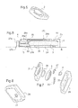
- the device 1 comprises a support 2 which may comprise, as illustrated, an upper part 2b and a lower part 2a movable relative to each other, for example in translation along an axis X which is for example oriented vertically .
- a support 2 which may comprise, as illustrated, an upper part 2b and a lower part 2a movable relative to each other, for example in translation along an axis X which is for example oriented vertically .
- Each of the parts 2a and 2b for example has a generally flattened shape perpendicular to the axis X.
- the parts 2a and 2b of the support are for example made of an electrically insulating material, for example a thermoplastic material, for example a polyolefin or silicone, ceramic, cardboard, paper or wood.
- a thermoplastic material for example a polyolefin or silicone, ceramic, cardboard, paper or wood.
- the device 1 may comprise a battery 3 and an electrical component 4, which is in the example described a light source, for example a light emitting diode, CMS type.
- a light source for example a light emitting diode, CMS type.
- the battery 3 may be a button cell, for example CR 12-20 possibly rechargeable.
- the two parts 2a and 2b are limited in their movement spaced apart from each other, for example by snapping the two parts into one another.
- the electric device 1 represented in Figures 1 and 2 has three electrical conductors 9, 10, 11 mechanically attached to the support 2.
- the first and second conductors 9 and 10 are for example retained on the upper part 2b of the support and the third conductor 11 can be held against the lower part 2a of the support by the stack 3 when it is placed in the housing 5, as one can see it on the figure 2 .
- the electrical component 4 can be connected to its first terminal at a first end 9a of the first conductor 9 and at its second terminal at a first end 10a of the second conductor 10.
- the first conductor 9 is, in the example described, a flexible conductor whose portion 9b extends between the upper portion 2b and the lower portion 2a of the support, for example obliquely, as illustrated.
- This first conductor 9 has a second end 9c connected to a first pole of the battery 3.
- the second conductor 10 has a second end 10b, which can lead to a through passage 12 formed in the wall of the upper part 2b.
- the first and second conductors 9 and 10 may comprise holes 14 in which are engaged pins 15 made by molding with the upper wall 16 of the upper part 2b.
- the holes 14 contribute to immobilizing the conductors 9 and 10 together with the electrical component 4.
- the pins 15 are riveted.
- the ends of the first and second conductors 9 and 10 coming into contact with the electrical component 4 are formed, in the illustrated example, by returns downwards.
- the third conductor 11 may have, as in the example illustrated, a doubly bent shape. It comprises a first end 11a in contact with the second pole of the stack 3 and a median portion 11b extending between the lower part 2a and the upper part 2b of the support 2, this median portion 11b passing through the passage 12. It also comprises a second end 11c formed by a return to the inside.
- the electrical device 1 is shown when a force is exerted on the latter along the axis X, which corresponds to the case where the object, under which the electric device 1 is fixed or to which the electric device 1 belongs, has been placed on a flat surface S.
- the electrical circuit is open, because of the clearance between the ends 10b and 11c, as can be seen in FIG. figure 3 .
- the support 2 is for example monolithic, contrary to what has been described with reference to the Figures 1 to 3 and may include a first housing 20 for receiving the battery 3 and a second housing 21 for receiving the electrical component 4, which is for example a light source, for example a CMS-type LED, as in the example of FIGS. Figures 1 to 3 .
- the first housing 20 is for example open at its two axial ends 22 and 24.
- the support 2 comprises in the example of Figures 4 to 6 teeth 23 at its upper end 22, to hold the stack 3 in the housing 20.
- the electrical device 1 comprises electrical conductors mechanically hooked on the support 2, these conductors comprising a first conductor 26 and a second conductor 27.
- the first conductor 26 may comprise a flexible portion and have a first fixed end 26a connected to a first terminal of the electrical component 4 and received in the second housing 21 and a second free end 26b, arranged to be applied against a first pole of the stack, so as to urge it downward.
- the second electrical conductor 27 is for example of bent shape, comprising a first end 27a connected to a second terminal of the electrical component 4 and received in the second housing 21, and a second end 27b opening on the lower end 24 of the first housing 20 .
- the first conductor 26 and the second conductor 27 are for example retained on the support by holes 14 in which are received pins 15 of the support, held by means of returns 26c and 27c resting against corresponding counter surfaces of the support by the electrical component 4.
- the device 1 may also include an intermediate element projecting on the underside of the support when the device is lifted.
- this intermediate element is a pellet 28 bonded to the lower face of the cell 3, for example made of a cellular or elastomeric material.
- the pellet 28 may help to prevent the object from sliding on the surface on which it is placed.
- the battery 3 can move in the housing 20 under the elastic return effect of the flexible portion 26b, and, when moving, come to the contact of the second end 27b, which closes the electrical circuit between the battery 3 and the electrical component 4, while the chip 28 protrudes on the lower surface of the support 2, as shown in FIGS. figures 12 and 14 .
- the electrical device 1 may comprise a base 29 comprising a housing 30 arranged to receive the support 2.
- the base 29 is for example fixed by gluing, by welding, in particular by ultrasound, or by embedding under the object, and the support 2 is fixed in the housing 30, for example by gluing or embedding.
- the base 29 comprises, for example, as illustrated in FIG. figure 8 , an opening 31 intended to be superimposed on the electrical component 4 when the latter is positioned in the housing 30.
- the electrical component 4 is a light source
- the light emitted by the latter can propagate through the opening 31.
- the base 29 is made of a transparent material.
- the base 29 may be of any shape, depending for example on the shape of the bottom wall of the conditioning device under which the electrical device 1 is fixed.
- the base 29 has a diamond shape and in the example of the figure 9 , the base 29 has a rectangular shape but could still be circular, elliptical, annular or polygonal.
- the base 29 can also be made monolithically with the object intended to be illuminated by the light source carried by the support 2.
- the first conductor 26 has an arcuate shape.
- the lower wall of the support 2 is largely perforated at the first housing 20, the bottom of the latter comprising a material bridge 32 and two teeth 33.
- the material bridge 32 acts as an intermediate element, comprising a not shown relief for lifting the stack 3 in the first housing 20 when the device rests on a horizontal flat surface.
- the material bridge 32 is replaced by a lug bearing a relief 38 which acts as an intermediate element projecting on the underside of the device when the latter is raised and for lifting the battery in the first housing when the device rests on a horizontal flat surface.
- the first conductor 26 has at its first end 26a a straight portion 26c intended to be held against the support 2 by friction against the electrical component 4 when the latter and the first conductor 26 are both arranged in the second housing 21.
- the bottom wall of the first housing 20 comprises, in the illustrated example, teeth 33 for retaining the stack.
- the electrical device 1 comprises a holding film 35, comprising for example a first face covered with an adhesive and intended for fixing to the support 2 and a second face on which information, for example commercial references or a list of ingredients, can be printed, and by which the device can rest.
- the holding film 35 may include an opening 36 for the passage of the chip 28 bonded under the battery 3. This opening 36 may have a smaller diameter than the first housing 20, so as to allow the film 35 to retain the battery 3 on the support.
- the device 1 may comprise a tongue 37 of insulating material, which is for example inserted between the stack 3 and the first conductor 26 before the first use and removed by the user during the first use.
- the teeth 23 of the upper wall 22 extend in an arc in the first housing 20.
- the support 2 comprises a first housing 40 and a second housing 41 for each receiving a battery 3, and a third housing 42 for receiving the electrical component 4.
- the two batteries 3 are arranged in the housings 40 and 41 with polarities inverted with respect to each other.
- the electrical device 1 comprises electrical conductors mechanically retained on the support 2.
- These conductors comprise, in the example considered, two first conductors 45 comprising first ends 45a each connected to a respective pole of a stack 3 and second ends 45b each connected to a respective terminal of the electrical component 4.
- the ends 45b can be formed by tight returns between the electrical component 4 and a counter-surface of the support and the conductors 45 may include holes in which are engaged pins of the support.
- the electrical device 1 further comprises two second conductors 46, for example of bent shape in the same plane parallel to the plane of the blades, comprising a first end 46a connected to the other pole of the corresponding cell 3 and having a second end 46b.
- the electrical device 1 further comprises a third conductor 47 which is received in a housing 43.
- the support 2 is made of elastomeric material and comprises a deformable portion 48 defined by at least one thinned area 49 of the support 2 and on which the third conductor 47 is mechanically hooked.
- the support 2 is made of non-elastomeric plastic material and an elastically deformable part 48 made of elastomer is attached to the support 2, the third conductor 47 being mechanically attached to this part 48.
- FIG 22 an example of a packaging device 100 of a cosmetic or care product.
- This device 100 may comprise a container 101 containing the product, provided with a bottom wall 102.
- An electrical device 1 as described above is fixed, for example by gluing, welding or by embedding on this bottom wall 102.
- the invention is not limited to the examples which have just been described.
- the invention is not limited to a particular number of batteries 3.
- the battery 3 is replaced by a rechargeable battery and the object under which the electrical device 1 is attached or to which it belongs comprises a base for charging the battery when the object is placed on the base. When the object is grasped, the charging of the battery stops and the electrical component is powered.
- the electrical component 4 may be other than a light source, being for example a vibrating source, for example a disk motor driving in rotation an eccentric flyweight, a piezoelectric device, an electric heating element, or an electronic circuit intended to broadcast a message sound.
- a vibrating source for example a disk motor driving in rotation an eccentric flyweight, a piezoelectric device, an electric heating element, or an electronic circuit intended to broadcast a message sound.
Landscapes
- Chemical & Material Sciences (AREA)
- Chemical Kinetics & Catalysis (AREA)
- Electrochemistry (AREA)
- General Chemical & Material Sciences (AREA)
- Inorganic Chemistry (AREA)
- Battery Mounting, Suspending (AREA)
Applications Claiming Priority (1)
| Application Number | Priority Date | Filing Date | Title |
|---|---|---|---|
| FR0902665A FR2946491B1 (fr) | 2009-06-03 | 2009-06-03 | Dispositif electrique a declenchement automatique par soulevement. |
Publications (2)
| Publication Number | Publication Date |
|---|---|
| EP2259366A1 EP2259366A1 (fr) | 2010-12-08 |
| EP2259366B1 true EP2259366B1 (fr) | 2012-12-26 |
Family
ID=41395783
Family Applications (1)
| Application Number | Title | Priority Date | Filing Date |
|---|---|---|---|
| EP10164895A Not-in-force EP2259366B1 (fr) | 2009-06-03 | 2010-06-03 | Dispositif électrique à déclenchement automatique par soulèvement. |
Country Status (4)
| Country | Link |
|---|---|
| US (1) | US8506110B2 (es) |
| EP (1) | EP2259366B1 (es) |
| ES (1) | ES2401260T3 (es) |
| FR (1) | FR2946491B1 (es) |
Families Citing this family (5)
| Publication number | Priority date | Publication date | Assignee | Title |
|---|---|---|---|---|
| CA2754583A1 (en) * | 2010-10-04 | 2012-04-04 | Bradley D. Pedersen | Activatable packaged articles |
| CN102790192A (zh) * | 2011-05-19 | 2012-11-21 | 鸿富锦精密工业(深圳)有限公司 | 电池座 |
| FR3001330B1 (fr) * | 2013-01-21 | 2015-01-30 | Seribase Ind | Dispositif de faible encombrement pour mettre en fonctionnement un système lumineux, sonore ou motorisé lorsque celui-ci se trouve dans des conditions de positionnement ou d'orientation particulières |
| US9263716B2 (en) * | 2013-02-21 | 2016-02-16 | Lutron Electronics Co., Inc. | Monolithic battery holder having resilient retention strap for use in battery-powered sensor |
| JP6692085B1 (ja) * | 2019-05-25 | 2020-05-13 | 薫 冨塚 | 電池ボックス。 |
Family Cites Families (11)
| Publication number | Priority date | Publication date | Assignee | Title |
|---|---|---|---|---|
| US2177337A (en) * | 1937-11-20 | 1939-10-24 | Stein Alexander | Automatic illuminated glass holder |
| US5785407A (en) * | 1996-11-18 | 1998-07-28 | Marpole International Inc. | Illuminable container |
| US7401935B2 (en) * | 1999-09-17 | 2008-07-22 | Vanderschuit Carl R | Beverage accessory devices |
| IT1318520B1 (it) * | 2000-05-16 | 2003-08-27 | Henkel Spa | Contenitore per profumo con generatore di suoni o luce. |
| WO2004017789A1 (ja) * | 2002-07-30 | 2004-03-04 | Yoshida Industry Co., Ltd. | 収納ケース |
| US20060044786A1 (en) * | 2004-08-25 | 2006-03-02 | Dennis Johnson | Illuminating base |
| US7189020B2 (en) | 2005-05-12 | 2007-03-13 | Sdi Corporation | Pushbutton controlled correction tape assembly |
| US20060274527A1 (en) | 2005-06-04 | 2006-12-07 | Michael Langone | Apparatus for providing illuminated images associated with containers |
| JP2007060406A (ja) * | 2005-08-25 | 2007-03-08 | Sharp Corp | 電気機器 |
| US7878676B2 (en) * | 2008-08-20 | 2011-02-01 | Jacek Helenowski | Cosmetic housing |
| US20100182770A1 (en) * | 2009-01-20 | 2010-07-22 | Huang Jung-Hui | Makeup palette |
-
2009
- 2009-06-03 FR FR0902665A patent/FR2946491B1/fr not_active Expired - Fee Related
-
2010
- 2010-06-03 US US12/793,449 patent/US8506110B2/en not_active Expired - Fee Related
- 2010-06-03 EP EP10164895A patent/EP2259366B1/fr not_active Not-in-force
- 2010-06-03 ES ES10164895T patent/ES2401260T3/es active Active
Also Published As
| Publication number | Publication date |
|---|---|
| ES2401260T3 (es) | 2013-04-18 |
| FR2946491A1 (fr) | 2010-12-10 |
| US20100315767A1 (en) | 2010-12-16 |
| FR2946491B1 (fr) | 2012-12-14 |
| US8506110B2 (en) | 2013-08-13 |
| EP2259366A1 (fr) | 2010-12-08 |
Similar Documents
| Publication | Publication Date | Title |
|---|---|---|
| EP2259366B1 (fr) | Dispositif électrique à déclenchement automatique par soulèvement. | |
| EP1157398B1 (fr) | Commutateur electrique individuel etanche fixe par embo tement sur une plaque a circuits | |
| FR2799570A1 (fr) | Commutateur electrique perfectionne a effet tactile a plusieurs voies et a organe de declenchement unique | |
| EP0024364B1 (fr) | Dispositif de maintien d'une pile dans une montre-bracelet électronique | |
| EP3206260A1 (fr) | Appareil électrique ayant une borne de connexion à pression avec une agrafe de support guidant et limitant la déformation élastique du ressort de contact | |
| EP3179533B1 (fr) | Appareil électronique portable muni d'une enceinte de pile | |
| EP0845718B1 (fr) | Dispositif d'interrupteur électrique sur un circuit imprimé, et montre comportant un tel dispositif | |
| FR2849953A1 (fr) | Dispositif de commutation a source lumineuse integree. | |
| FR3060197A1 (fr) | Commutateur electrique | |
| FR2629943A1 (fr) | Interrupteur electrique a effet tactile | |
| EP0004503B1 (fr) | Nouveau boîtier pour lampe électrique de poche | |
| FR2489702A1 (fr) | Interrupteur manoeuvre par une bille roulant sur lui et son application dans un billard electrique | |
| FR2806836A1 (fr) | Adaptateur de batterie | |
| FR2849954A1 (fr) | Dispositif de commutation a source lumineuse integree. | |
| EP0866483B1 (fr) | Coupe-batterie bi-stable à verrouillage mécanique | |
| EP3054359A1 (fr) | Dispositif de montage d'une source d'énergie électrique | |
| FR2569047A1 (fr) | Porte-fusible antichoc | |
| FR2993700A1 (fr) | "commutateur electrique a effet tactile a bruit reduit et procede d'attenuation du bruit d'un commutateur a effet tactile" | |
| FR2960396A1 (fr) | Chauffe-plat electrique et chargeur associe | |
| EP1432052B1 (fr) | Dispositif de montage de source d'energie pour appareil electronique portable | |
| EP3010099B1 (fr) | Panneau de disjoncteurs | |
| FR3028356A1 (fr) | Borne de connexion electrique a vis imperdable | |
| EP3659629B1 (fr) | Diffuseur d'huile essentielle | |
| FR2864691A1 (fr) | Commutateur electrique lumineux a effet tactile | |
| EP3489980B1 (fr) | Dispositif de commande de type bouton-poussoir à architecture plate |
Legal Events
| Date | Code | Title | Description |
|---|---|---|---|
| PUAI | Public reference made under article 153(3) epc to a published international application that has entered the european phase |
Free format text: ORIGINAL CODE: 0009012 |
|
| 17P | Request for examination filed |
Effective date: 20100603 |
|
| AK | Designated contracting states |
Kind code of ref document: A1 Designated state(s): AL AT BE BG CH CY CZ DE DK EE ES FI FR GB GR HR HU IE IS IT LI LT LU LV MC MK MT NL NO PL PT RO SE SI SK SM TR |
|
| AX | Request for extension of the european patent |
Extension state: BA ME RS |
|
| 17Q | First examination report despatched |
Effective date: 20110204 |
|
| GRAP | Despatch of communication of intention to grant a patent |
Free format text: ORIGINAL CODE: EPIDOSNIGR1 |
|
| RIC1 | Information provided on ipc code assigned before grant |
Ipc: H01M 2/10 20060101AFI20120626BHEP Ipc: H01M 2/20 20060101ALI20120626BHEP Ipc: A45D 40/00 20060101ALI20120626BHEP Ipc: A45D 34/00 20060101ALI20120626BHEP Ipc: H01M 2/34 20060101ALI20120626BHEP |
|
| GRAS | Grant fee paid |
Free format text: ORIGINAL CODE: EPIDOSNIGR3 |
|
| GRAA | (expected) grant |
Free format text: ORIGINAL CODE: 0009210 |
|
| AK | Designated contracting states |
Kind code of ref document: B1 Designated state(s): AL AT BE BG CH CY CZ DE DK EE ES FI FR GB GR HR HU IE IS IT LI LT LU LV MC MK MT NL NO PL PT RO SE SI SK SM TR |
|
| REG | Reference to a national code |
Ref country code: GB Ref legal event code: FG4D Free format text: NOT ENGLISH |
|
| REG | Reference to a national code |
Ref country code: CH Ref legal event code: EP |
|
| REG | Reference to a national code |
Ref country code: AT Ref legal event code: REF Ref document number: 590868 Country of ref document: AT Kind code of ref document: T Effective date: 20130115 |
|
| REG | Reference to a national code |
Ref country code: DE Ref legal event code: R096 Ref document number: 602010004273 Country of ref document: DE Effective date: 20130228 |
|
| REG | Reference to a national code |
Ref country code: ES Ref legal event code: FG2A Ref document number: 2401260 Country of ref document: ES Kind code of ref document: T3 Effective date: 20130418 |
|
| PG25 | Lapsed in a contracting state [announced via postgrant information from national office to epo] |
Ref country code: NO Free format text: LAPSE BECAUSE OF FAILURE TO SUBMIT A TRANSLATION OF THE DESCRIPTION OR TO PAY THE FEE WITHIN THE PRESCRIBED TIME-LIMIT Effective date: 20130326 Ref country code: FI Free format text: LAPSE BECAUSE OF FAILURE TO SUBMIT A TRANSLATION OF THE DESCRIPTION OR TO PAY THE FEE WITHIN THE PRESCRIBED TIME-LIMIT Effective date: 20121226 Ref country code: LT Free format text: LAPSE BECAUSE OF FAILURE TO SUBMIT A TRANSLATION OF THE DESCRIPTION OR TO PAY THE FEE WITHIN THE PRESCRIBED TIME-LIMIT Effective date: 20121226 Ref country code: HR Free format text: LAPSE BECAUSE OF FAILURE TO SUBMIT A TRANSLATION OF THE DESCRIPTION OR TO PAY THE FEE WITHIN THE PRESCRIBED TIME-LIMIT Effective date: 20121226 Ref country code: SE Free format text: LAPSE BECAUSE OF FAILURE TO SUBMIT A TRANSLATION OF THE DESCRIPTION OR TO PAY THE FEE WITHIN THE PRESCRIBED TIME-LIMIT Effective date: 20121226 |
|
| REG | Reference to a national code |
Ref country code: AT Ref legal event code: MK05 Ref document number: 590868 Country of ref document: AT Kind code of ref document: T Effective date: 20121226 |
|
| REG | Reference to a national code |
Ref country code: LT Ref legal event code: MG4D |
|
| REG | Reference to a national code |
Ref country code: NL Ref legal event code: VDEP Effective date: 20121226 |
|
| PG25 | Lapsed in a contracting state [announced via postgrant information from national office to epo] |
Ref country code: SI Free format text: LAPSE BECAUSE OF FAILURE TO SUBMIT A TRANSLATION OF THE DESCRIPTION OR TO PAY THE FEE WITHIN THE PRESCRIBED TIME-LIMIT Effective date: 20121226 Ref country code: LV Free format text: LAPSE BECAUSE OF FAILURE TO SUBMIT A TRANSLATION OF THE DESCRIPTION OR TO PAY THE FEE WITHIN THE PRESCRIBED TIME-LIMIT Effective date: 20121226 Ref country code: GR Free format text: LAPSE BECAUSE OF FAILURE TO SUBMIT A TRANSLATION OF THE DESCRIPTION OR TO PAY THE FEE WITHIN THE PRESCRIBED TIME-LIMIT Effective date: 20130327 |
|
| PG25 | Lapsed in a contracting state [announced via postgrant information from national office to epo] |
Ref country code: SK Free format text: LAPSE BECAUSE OF FAILURE TO SUBMIT A TRANSLATION OF THE DESCRIPTION OR TO PAY THE FEE WITHIN THE PRESCRIBED TIME-LIMIT Effective date: 20121226 Ref country code: AT Free format text: LAPSE BECAUSE OF FAILURE TO SUBMIT A TRANSLATION OF THE DESCRIPTION OR TO PAY THE FEE WITHIN THE PRESCRIBED TIME-LIMIT Effective date: 20121226 Ref country code: EE Free format text: LAPSE BECAUSE OF FAILURE TO SUBMIT A TRANSLATION OF THE DESCRIPTION OR TO PAY THE FEE WITHIN THE PRESCRIBED TIME-LIMIT Effective date: 20121226 Ref country code: IS Free format text: LAPSE BECAUSE OF FAILURE TO SUBMIT A TRANSLATION OF THE DESCRIPTION OR TO PAY THE FEE WITHIN THE PRESCRIBED TIME-LIMIT Effective date: 20130426 Ref country code: CZ Free format text: LAPSE BECAUSE OF FAILURE TO SUBMIT A TRANSLATION OF THE DESCRIPTION OR TO PAY THE FEE WITHIN THE PRESCRIBED TIME-LIMIT Effective date: 20121226 Ref country code: BG Free format text: LAPSE BECAUSE OF FAILURE TO SUBMIT A TRANSLATION OF THE DESCRIPTION OR TO PAY THE FEE WITHIN THE PRESCRIBED TIME-LIMIT Effective date: 20130326 |
|
| PG25 | Lapsed in a contracting state [announced via postgrant information from national office to epo] |
Ref country code: RO Free format text: LAPSE BECAUSE OF FAILURE TO SUBMIT A TRANSLATION OF THE DESCRIPTION OR TO PAY THE FEE WITHIN THE PRESCRIBED TIME-LIMIT Effective date: 20121226 Ref country code: PL Free format text: LAPSE BECAUSE OF FAILURE TO SUBMIT A TRANSLATION OF THE DESCRIPTION OR TO PAY THE FEE WITHIN THE PRESCRIBED TIME-LIMIT Effective date: 20121226 Ref country code: NL Free format text: LAPSE BECAUSE OF FAILURE TO SUBMIT A TRANSLATION OF THE DESCRIPTION OR TO PAY THE FEE WITHIN THE PRESCRIBED TIME-LIMIT Effective date: 20121226 Ref country code: PT Free format text: LAPSE BECAUSE OF FAILURE TO SUBMIT A TRANSLATION OF THE DESCRIPTION OR TO PAY THE FEE WITHIN THE PRESCRIBED TIME-LIMIT Effective date: 20130426 |
|
| PG25 | Lapsed in a contracting state [announced via postgrant information from national office to epo] |
Ref country code: DK Free format text: LAPSE BECAUSE OF FAILURE TO SUBMIT A TRANSLATION OF THE DESCRIPTION OR TO PAY THE FEE WITHIN THE PRESCRIBED TIME-LIMIT Effective date: 20121226 |
|
| PLBE | No opposition filed within time limit |
Free format text: ORIGINAL CODE: 0009261 |
|
| STAA | Information on the status of an ep patent application or granted ep patent |
Free format text: STATUS: NO OPPOSITION FILED WITHIN TIME LIMIT |
|
| PG25 | Lapsed in a contracting state [announced via postgrant information from national office to epo] |
Ref country code: CY Free format text: LAPSE BECAUSE OF FAILURE TO SUBMIT A TRANSLATION OF THE DESCRIPTION OR TO PAY THE FEE WITHIN THE PRESCRIBED TIME-LIMIT Effective date: 20121226 |
|
| 26N | No opposition filed |
Effective date: 20130927 |
|
| BERE | Be: lapsed |
Owner name: L'OREAL Effective date: 20130630 |
|
| REG | Reference to a national code |
Ref country code: DE Ref legal event code: R097 Ref document number: 602010004273 Country of ref document: DE Effective date: 20130927 |
|
| PG25 | Lapsed in a contracting state [announced via postgrant information from national office to epo] |
Ref country code: MC Free format text: LAPSE BECAUSE OF FAILURE TO SUBMIT A TRANSLATION OF THE DESCRIPTION OR TO PAY THE FEE WITHIN THE PRESCRIBED TIME-LIMIT Effective date: 20121226 |
|
| REG | Reference to a national code |
Ref country code: IE Ref legal event code: MM4A |
|
| PG25 | Lapsed in a contracting state [announced via postgrant information from national office to epo] |
Ref country code: BE Free format text: LAPSE BECAUSE OF NON-PAYMENT OF DUE FEES Effective date: 20130630 |
|
| PG25 | Lapsed in a contracting state [announced via postgrant information from national office to epo] |
Ref country code: IE Free format text: LAPSE BECAUSE OF NON-PAYMENT OF DUE FEES Effective date: 20130603 |
|
| REG | Reference to a national code |
Ref country code: CH Ref legal event code: PL |
|
| PG25 | Lapsed in a contracting state [announced via postgrant information from national office to epo] |
Ref country code: MT Free format text: LAPSE BECAUSE OF FAILURE TO SUBMIT A TRANSLATION OF THE DESCRIPTION OR TO PAY THE FEE WITHIN THE PRESCRIBED TIME-LIMIT Effective date: 20121226 |
|
| PG25 | Lapsed in a contracting state [announced via postgrant information from national office to epo] |
Ref country code: LI Free format text: LAPSE BECAUSE OF NON-PAYMENT OF DUE FEES Effective date: 20140630 Ref country code: CH Free format text: LAPSE BECAUSE OF NON-PAYMENT OF DUE FEES Effective date: 20140630 |
|
| PG25 | Lapsed in a contracting state [announced via postgrant information from national office to epo] |
Ref country code: SM Free format text: LAPSE BECAUSE OF FAILURE TO SUBMIT A TRANSLATION OF THE DESCRIPTION OR TO PAY THE FEE WITHIN THE PRESCRIBED TIME-LIMIT Effective date: 20121226 |
|
| PG25 | Lapsed in a contracting state [announced via postgrant information from national office to epo] |
Ref country code: TR Free format text: LAPSE BECAUSE OF FAILURE TO SUBMIT A TRANSLATION OF THE DESCRIPTION OR TO PAY THE FEE WITHIN THE PRESCRIBED TIME-LIMIT Effective date: 20121226 |
|
| PG25 | Lapsed in a contracting state [announced via postgrant information from national office to epo] |
Ref country code: LU Free format text: LAPSE BECAUSE OF NON-PAYMENT OF DUE FEES Effective date: 20130603 Ref country code: MK Free format text: LAPSE BECAUSE OF FAILURE TO SUBMIT A TRANSLATION OF THE DESCRIPTION OR TO PAY THE FEE WITHIN THE PRESCRIBED TIME-LIMIT Effective date: 20121226 Ref country code: HU Free format text: LAPSE BECAUSE OF FAILURE TO SUBMIT A TRANSLATION OF THE DESCRIPTION OR TO PAY THE FEE WITHIN THE PRESCRIBED TIME-LIMIT; INVALID AB INITIO Effective date: 20100603 |
|
| REG | Reference to a national code |
Ref country code: FR Ref legal event code: PLFP Year of fee payment: 7 |
|
| PGFP | Annual fee paid to national office [announced via postgrant information from national office to epo] |
Ref country code: DE Payment date: 20160601 Year of fee payment: 7 Ref country code: ES Payment date: 20160511 Year of fee payment: 7 Ref country code: GB Payment date: 20160601 Year of fee payment: 7 |
|
| PGFP | Annual fee paid to national office [announced via postgrant information from national office to epo] |
Ref country code: FR Payment date: 20160516 Year of fee payment: 7 |
|
| PGFP | Annual fee paid to national office [announced via postgrant information from national office to epo] |
Ref country code: IT Payment date: 20160621 Year of fee payment: 7 |
|
| REG | Reference to a national code |
Ref country code: DE Ref legal event code: R119 Ref document number: 602010004273 Country of ref document: DE |
|
| GBPC | Gb: european patent ceased through non-payment of renewal fee |
Effective date: 20170603 |
|
| REG | Reference to a national code |
Ref country code: FR Ref legal event code: ST Effective date: 20180228 |
|
| PG25 | Lapsed in a contracting state [announced via postgrant information from national office to epo] |
Ref country code: DE Free format text: LAPSE BECAUSE OF NON-PAYMENT OF DUE FEES Effective date: 20180103 Ref country code: GB Free format text: LAPSE BECAUSE OF NON-PAYMENT OF DUE FEES Effective date: 20170603 |
|
| PG25 | Lapsed in a contracting state [announced via postgrant information from national office to epo] |
Ref country code: FR Free format text: LAPSE BECAUSE OF NON-PAYMENT OF DUE FEES Effective date: 20170630 Ref country code: IT Free format text: LAPSE BECAUSE OF NON-PAYMENT OF DUE FEES Effective date: 20170603 |
|
| PG25 | Lapsed in a contracting state [announced via postgrant information from national office to epo] |
Ref country code: AL Free format text: LAPSE BECAUSE OF FAILURE TO SUBMIT A TRANSLATION OF THE DESCRIPTION OR TO PAY THE FEE WITHIN THE PRESCRIBED TIME-LIMIT Effective date: 20121226 |
|
| REG | Reference to a national code |
Ref country code: ES Ref legal event code: FD2A Effective date: 20181106 |
|
| PG25 | Lapsed in a contracting state [announced via postgrant information from national office to epo] |
Ref country code: ES Free format text: LAPSE BECAUSE OF NON-PAYMENT OF DUE FEES Effective date: 20170604 |