EP2258954A1 - Connected fasteners - Google Patents
Connected fasteners Download PDFInfo
- Publication number
- EP2258954A1 EP2258954A1 EP09728592A EP09728592A EP2258954A1 EP 2258954 A1 EP2258954 A1 EP 2258954A1 EP 09728592 A EP09728592 A EP 09728592A EP 09728592 A EP09728592 A EP 09728592A EP 2258954 A1 EP2258954 A1 EP 2258954A1
- Authority
- EP
- European Patent Office
- Prior art keywords
- nail
- ring
- fastener
- driving
- shaped
- Prior art date
- Legal status (The legal status is an assumption and is not a legal conclusion. Google has not performed a legal analysis and makes no representation as to the accuracy of the status listed.)
- Granted
Links
- 229920003002 synthetic resin Polymers 0.000 claims abstract description 13
- 239000000057 synthetic resin Substances 0.000 claims abstract description 13
- 238000004804 winding Methods 0.000 description 3
- 238000004519 manufacturing process Methods 0.000 description 2
- 239000000463 material Substances 0.000 description 2
- 239000004743 Polypropylene Substances 0.000 description 1
- 238000005452 bending Methods 0.000 description 1
- 238000007664 blowing Methods 0.000 description 1
- 238000007599 discharging Methods 0.000 description 1
- 239000002737 fuel gas Substances 0.000 description 1
- 230000004048 modification Effects 0.000 description 1
- 238000012986 modification Methods 0.000 description 1
- -1 polypropylene Polymers 0.000 description 1
- 229920001155 polypropylene Polymers 0.000 description 1
Images


Classifications
-
- F—MECHANICAL ENGINEERING; LIGHTING; HEATING; WEAPONS; BLASTING
- F16—ENGINEERING ELEMENTS AND UNITS; GENERAL MEASURES FOR PRODUCING AND MAINTAINING EFFECTIVE FUNCTIONING OF MACHINES OR INSTALLATIONS; THERMAL INSULATION IN GENERAL
- F16B—DEVICES FOR FASTENING OR SECURING CONSTRUCTIONAL ELEMENTS OR MACHINE PARTS TOGETHER, e.g. NAILS, BOLTS, CIRCLIPS, CLAMPS, CLIPS OR WEDGES; JOINTS OR JOINTING
- F16B15/00—Nails; Staples
- F16B15/08—Nails; Staples formed in integral series but easily separable
Definitions
- the present disclosure relates to a connecting fastener which is used for a tool for driving a fastener for which a driving source such as an air pressure or fuel gas is employed.
- a connecting system for a connecting fastener consisting of a plurality of fasters
- a wire connecting system of connecting welded shafts of the respective using parallel two wires.
- a linear connecting system of integrally bonding/connecting the plurality of fasteners onto a linear connecting belt of synthetic resin
- a connecting sheet system in which the fasteners are inserted held in upper and lower holding pieces projected from the upper and lower ends of a planar-sheet like connecting belt of synthetic resin at regular intervals in the same directions.
- the linear connecting system there is the system as disclosed in Patent Reference 1
- the connecting sheet system there is the system as disclosed in Patent Reference 2.
- the connected fasteners in driving, the connected fasteners are separated from the connecting sheet and the connecting sheet is discharged from the discharging slot of a fastener driving tool.
- the connecting sheet corresponding the length of the number of connected fasters is discharged and dangles from the driving tool. This hindered the work and reduced the working efficiency.
- the invention provides a connecting fastener capable of facilitating a driving operation, eliminating the need of scrapping a connecting member and being manufactured at low cost.
- a connecting fastener is provided with plurality of fasteners and a connecting member of synthetic resin connecting the plurality of fasteners.
- the connecting member includes a ring-shaped portion attached to so as to encircle a shaft of each fastener and a connecting portion connected to the ring-shaped portion encircling adjacent fasteners.
- an outer shape of the ring-shaped portion may be formed in a size approximately equal to a head of each fastener.
- the ring-shaped portion and the connecting portion may be formed in a sheet-shape.
- the ring-shaped portion may be formed wall-thick enough for the shaft of the fastener to be guidable in a driving direction in an ejecting mouth of the fastener driving tool, and the connecting portion may be formed wall-thin.
- the connecting portion may be formed at a position offset from a line connecting centers of adjacent ring-shaped portions.
- the connecting portion may be formed on the line connecting the centers of adjacent ring-shaped portions.
- a connecting nail 1 consists of a plurality of nails 3 connected through a connecting member 2 of synthetic resin such as polypropylene.
- the connecting member 2 has ring-shaped portions 4 and a connecting portion 5.
- the ring-shaped portions 4 each is attached so as to encircle the shaft 3a of each of the nails 3 connected.
- the connecting portion 5 connects the ring-shaped portions 4 adjacent to each other. It should be noted that the connecting member 2 connects the plurality of nails 3, but Fig. 1 illustrates only the manner of connecting two nails 3.
- the ring-shaped portions 4 each consists of an upper ring-shaped segment 4a and a lower ring-shaped segment 4b which are connected through a connecting piece 4c.
- the outer shape of the ring-shaped portion 4 is circular and has a size approximately equal to that of the head 3b of the nail 3.
- the connecting portion 5 consists of an upper connecting segment 5a and a lower connecting segment 5b which connect the upper ring-shaped segments 4a and the lower ring-shaped segments 4b, respectively.
- the upper ring-shaped segment 4a and the lower ring-shaped segment 4b are fit over the shaft 3a.
- the connecting portion 5 has strength enough to be broken when driving the fastener by a fastener driving tool.
- the ring-shaped portion 4 has strength enough to be held over the shaft 3a.
- the ring-shaped portion 4 may have the strength of the above magnitude in a state where the upper ring-shaped segment 4a and the lower ring-shaped segment 4b are integrally connected through the connecting piece 4c.
- the upper connecting segment 5a and the lower connecting segment 5b are formed at an offset position deviated towards the one side from the line connecting the centers of the adjacent ring-shaped portions 4, respectively.
- the connecting member 2 can be assembled by pressing a synthetic resin sheet "a” shown in Fig. 2 and bending the sheet "a".
- the ring-shaped portion 4 may not encircle the entire periphery of the shaft 3a of the nail 3. For example, as shown in Fig. 3 , it may be notched in a part 6.
- the connecting nail 1 structured as described above is wrapped in a state wound in a coil shape like a connecting nail of the ordinary wire connecting system.
- the upper connecting segment 5a and lower connecting segment 5b are formed at a position offset from the line connecting the centers of the adjacent upper ring-shaped segments 4a and lower ring-shaped segments 4b, respectively. Therefore, by winding the connecting nail 1 with the offset side oriented toward the outside of the coil, the winding diameter at the center can be reduced.
- the entire shape of the connecting nail 1 can be made compact. Accordingly, the magazine of a nail driver using the connecting nail 1 can be downsized.
- the connecting nail 1 wound in a coil shape is loaded in a cylindrical magazine (not shown).
- the connecting nail 1 loaded in the magazine is fed in the driving mouth of the driver successively from the nail 3 at the top.
- the nail 3 is driven by a driver 9 knocked by a knocking mechanism.
- the ring-shaped segments 4a, 4b of the connecting member 2 have the strength enough to be not deviated from the shaft 3a but held over the shaft 3a; and the connecting segments 5a, 5b have the strength enough to be broken. Therefore, with the ring-shaped portion 4 being held over the shaft 3a, the connecting portion 5 will be broken and separated from the connecting member 2 of a subsequent nail 3.
- the ring-shaped portion 4 is fixed in a state where it is sandwiched between the member to be nail-driven and the head of the nail 3.
- the subsequent nail 3 will be driven in the same manner. Accordingly, with a progress of the nail-driving work, the connecting member 2 will not dangle from the nail driver. As a result, the working efficiency can be remarkably improved as compared with the related-art work of driving out the connecting nail 1 using the connecting sheet.
- the ring-shaped portion 4 of the connecting nail 2 is formed in a circular shape in the size approximately equal to that of the head 3b of the nail 3. Therefore, when the nail 3 fed in the ejecting mouth 10 suffers from the blow by the driver 9, it can be guided in a driving direction without the shaft 3a and foot of the nail 3 wobbling within the ejecting mouth so that the nail 3 can be appropriately driven.
- the shape of the ring-shaped portion 4 is not limited to the circle, but may be, formed for example a toothed-wheel shape.
- the connecting member 2 is driven together with the nail 3, and fixed on the rear side of the head 3b of the nail 3. For this reason, it is not necessary to scrap the connecting member 2. Thus, the workability can be improved.
- the connecting member 2 can be easily manufactured by press-working a synthetic resin sheet. Only a single sheet permits the nails to be connected. Thus, the production cost can be reduced.
- the embodiment of the connecting nail 1 should not be limited in that described above.
- the connecting nail can be manufactured in the following various manners.
- the ring-shaped portion 4 of the synthetic resin connecting member 2 is formed wall-thick and in a size approximately equal to that of the head 3b of the nail 3.
- the connecting portion 5 is formed wall-thin.
- the connecting portion 5 is wall-thin and has a width corresponding to that of the ring-shaped portion 4, but has an opening 7 formed at the center so as to give the strength enough to be broken in driving.
- the connecting portion 5 is formed at the position offset from the line connecting the centers of the adjacent ring-shaped portions 4.
- the ring-shaped portion 4 is not required to encircle the entire periphery of the shaft 3a of the nail 3. As shown in Fig. 7 , it may be notched in a part 6.
- the ring-shaped portion 4 of the connecting member 2 has the strength enough to be not deviated from the shaft 3a but held over the shaft 3a in driving out; and the connecting portion 5 has the strength enough to be broken in driving out. Therefore, with the ring-shaped portion 4 being held over the shaft 3a, the connecting portion 5 will be broken and separated from the connecting member 2 of a subsequent nail 3. Accordingly, with a progress of the nail-driving work, the connecting member 2 will not dangle from the nail driver, thereby remarkably improving the working efficiency. Further, at the time of completing the sequential driving out of the connecting nail 1, the connecting member 2 is driven together with the nail 3, and fixed on the rear side of the head 3b of the nail 3. For this reason, it is not necessary to scrap the connecting member 2. Thus, the workability is remarkably improved.
- the ring-shape portion 4 is wall-thick and difficult to be deformed.
- the shaft 3a of the nail 3 can be more surely guided in the driving direction.
- the connecting portion 5 is formed at the position offset from the line connecting the centers of the adjacent ring-shaped portions 4. For this reason, the entire shape of the connecting nail 1 can be made compact.
- the connecting member 2 can be easily manufactured by press-working a wall-thick synthetic resin sheet and making the opening 7. Further, only a single sheet permits the nails to be connected. Thus, the production cost can be reduced.
- the ring-shaped portion 4 of the connecting member 2 is formed in a circular shape in the size approximately equal to that of the head 3b of the nail 3. Therefore, in nail-driving, the shaft 3a and foot of the nail 3 can be guided in the driving direction.
- a single nail shaft 3a is provided with a guide cylinder 8 without the connecting portion 5, and a synthetic resin connecting member 2 having a ring-shaped portion 4 with the connecting portion 5.
- the guide cylinder 8 serves to guide the shaft 3a and foot of the nail 3 when the nail 3 is driven.
- the guide cylinder 8 and the connecting member 2 are arranged in a superposed manner.
- a plurality of ring-shaped portions 4 are connected with each other through the connecting portion 5. Both the ring-shaped portion 4 and the connecting portion 5 are formed wall-thin and the connecting portion 5 is formed at the position offset from the line connecting the centers of the adjacent ring-shaped portions 4.
- the guide cylinder 8 and the ring-shaped portion 4 are formed in the size approximately equal to that of the head 3b of the nail 3.
- the ring-shaped portion 4 is not required to encircle the entire periphery of the shaft 3a of the nail 3. As shown in Fig. 9 , it may be notched in a part 6. It may be formed in a toothed-wheel shape. Further, when driving the nail 3 by the nail driver, the ring-shaped portion 4 has strength enough to be held over the shaft 3a and the connecting portion 5 has strength enough to be broken.
- the two nails 3 are connected by a single connecting portion 5.
- the connecting nail 1 is apt to bend and so can be wholly wound compactly. Since the connecting portion 5 is formed at the offset position, the entire shape of the connecting nail 1 can be made further compact.
- Each nail 3 is provided with the guide cylinder 8 and ring-shaped portion 4. For this reason, in nail-driving, the shaft 3a and foot of the nail 3 can be more surely guided in the driving direction.
- the connecting member 2 can be manufactured at low cost by press-working a thin sheet material.
- the connecting portion 5 may be arranged on the line connecting the centers of the adjacent ring-shaped portions 4.
- the connecting nail 1 loaded in a vertical magazine is guided to the driving mouth of the nail driver, with the starting end of the connecting nail 1 pulled out from the vertical magazine, the connecting nail 1 must be twisted by 90° and thereafter guided into the driving mouth of the nail driver.
- the connecting nail 1 since there is only a single connecting portion 5 of the adjacent nails 3 in the connecting nail 1, the connecting nail 1 can be easily twisted.
- limitation to the layout of the vertical magazine is trivial and the tool to be used can be made compact.
- the connecting nail is hard to be twisted. For this reason, limitation to the layout is significant and the tool itself will become bulky.
- the connecting nail 1 is once taken out from the nail driver; and immediately before nail-driving is started on the next day again, the connecting nail 1 taken out is loaded in a nose portion.
- Such a remaining connecting nail 1 is not still coil-like. Therefore, where the connecting nail 1 is loaded in the tool, if the connecting portion 5 is formed at the offset position, since both sides of the connecting nail 1 are not identical, attention must be paid on whether the connecting nail 1 should be loaded from which end. However, in the case of the connecting nail 1 in which the connecting portion 5 is formed on the line connecting the centers of the adjacent ring-shaped portions 4 as shown in Fig. 10 , since both sides are identical, the connecting nail 1 may be loaded early from either end. Thus, the working is facilitated.
- the connecting portion may be arranged on the line connecting the centers of the adjacent ring-shaped portions 4.
- the manner in which the single nail shaft 3a is provided with the guide cylinder 8 without the connecting portion 5 and the synthetic resin connecting member 2 having the ring-shaped portion 4 with the connecting portion 5 should not be limited to that described above.
- the guide cylinder 8 may be fixedly fit near the head 3b of the nail 3 and at the intermediate position of the shaft 3a, the same connecting member 2 as shown in Fig. 8 may be connected to the nail 3.
- the guide cylinder 8 and the ring-shaped portion 4 are formed in the size approximately equal to that of the head 3b of the nail 3.
- the ring-shaped portion 4 is not required to encircle the entire periphery of the shaft 3a of the nail 3. It may be notched in a part 6, or formed in a toothed-wheel shape. Further, when driving the nail 3 by the nail driver, the ring-shaped portion 4 has a strength enough to be held over the shaft 3a and the connecting portion 5 has a strength enough to be broken.
- the two nails 3 are connected by a single connecting portion 5. For this reason, the nail 1 is apt to bend and so can be wholly wound compactly. Since the connecting portion 5 is formed at the offset position, the entire shape of the connecting nail 1 can be made further compact.
- Each nail 3 is provided with the guide cylinder 8 and ring-shaped portion 4. In addition, the nails 3 are separated from each other. For this reason, in nail-driving, the shaft 3a and foot of the nail 3 can be surely guided in the driving direction.
- the guide cylinder 8 can be formed by cutting a lengthy tubular member.
- the connecting member 2 can be formed by press-working a thin sheet material. Thus, the connecting nail can be manufactured at low cost.
- the connecting portion 5 may be arranged on the line connecting the centers of the adjacent ring-shaped portions 4.
- the connecting member 2, as shown in Figs. 12(a) and 12(b) may be formed wall-thick.
- the ring-shaped portion 4 may be notched in a part 6, or may be formed in a toothed-wheel shape.
- the connecting portion may be notched to be wall-thin so that it can be easily broken.
- the present invention is used for a connecting fastener for use in a fastener driving tool.
Abstract
Description
- The present disclosure relates to a connecting fastener which is used for a tool for driving a fastener for which a driving source such as an air pressure or fuel gas is employed.
- Generally, as a connecting system for a connecting fastener consisting of a plurality of fasters, there is a wire connecting system of connecting welded shafts of the respective using parallel two wires. Further, there are also a linear connecting system of integrally bonding/connecting the plurality of fasteners onto a linear connecting belt of synthetic resin, and a connecting sheet system in which the fasteners are inserted held in upper and lower holding pieces projected from the upper and lower ends of a planar-sheet like connecting belt of synthetic resin at regular intervals in the same directions. As an example of the linear connecting system, there is the system as disclosed in
Patent Reference 1, and as an example of the connecting sheet system, there is the system as disclosed inPatent Reference 2. - Patent Reference 1:
JP-A-2003-301824 - Patent Reference 2:
JP-A-2000-240622 - However, the above related-art systems are problematic in the following points. In the connecting faster of the wire connecting system, wires will be scattered in driving. In the linear connecting system using a synthetic resin connecting member, the connecting faster cannot be wound in a coil shape, and cannot be manufactured at low cost from the standpoint of forming.
- In the connecting sheet system, in driving, the connected fasteners are separated from the connecting sheet and the connecting sheet is discharged from the discharging slot of a fastener driving tool. The connecting sheet corresponding the length of the number of connected fasters is discharged and dangles from the driving tool. This hindered the work and reduced the working efficiency.
- After completion of driving a series of connecting nails, the connecting sheet must be scrapped as rubbish. This work was troublesome.
- The invention provides a connecting fastener capable of facilitating a driving operation, eliminating the need of scrapping a connecting member and being manufactured at low cost.
- According to a first aspect of the invention, a connecting fastener is provided with plurality of fasteners and a connecting member of synthetic resin connecting the plurality of fasteners. The connecting member includes a ring-shaped portion attached to so as to encircle a shaft of each fastener and a connecting portion connected to the ring-shaped portion encircling adjacent fasteners. When driving the fastener by a fastener driving tool, the ring-shaped portion has strength enough to be held over the shaft, and the connecting portion has strength enough to be broken.
- According to a second aspect of the invention, an outer shape of the ring-shaped portion may be formed in a size approximately equal to a head of each fastener.
- According to a third aspect of the invention, the ring-shaped portion and the connecting portion may be formed in a sheet-shape.
- According to a fourth aspect of the invention, the ring-shaped portion may be formed wall-thick enough for the shaft of the fastener to be guidable in a driving direction in an ejecting mouth of the fastener driving tool, and the connecting portion may be formed wall-thin.
- According to a fifth aspect of the invention, the connecting portion may be formed at a position offset from a line connecting centers of adjacent ring-shaped portions.
- According to a sixth aspect of the invention, the connecting portion may be formed on the line connecting the centers of adjacent ring-shaped portions.
- Other aspects and advantages of the invention will be apparent from the following description, the drawings and the claims.
-
-
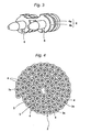
Fig. 1 is a perspective view of a connecting nail according to the invention; -
Fig. 2 is a developed view of a connecting member; -
Fig. 3 is a perspective view of a ring-shaped portion notched in part; -
Fig. 4 is a plan view simply showing the state where a connecting nail is wound in a coil shape; -
Fig. 5 is a sectional view of an ejecting mouth in the blowing state of a connecting nail; -
Fig. 6 is a perspective view of another manner of a connecting nail; -
Fig. 7 is a perspective view showing the state where a ring-shaped portion is notched in part; -
Fig. 8 is further another manner of a connecting nail; -
Fig. 9 is a perspective view showing the state where a ring-shaped portion is notched in part; -
Fig. 10 is a further manner of a connecting nail; -
Fig. 11 (a) and Fig. 11(b) are a perspective view of a connecting nail in a state connected by a wall-thin connecting member in a different manner; and -
Fig. 12(a) and Fig. 12(b) are a perspective view of a connecting nail in a state connected by a wall-thin connecting member in a different manner. - Hereinafter, an explanation will be given of a connecting nail according to exemplary embodiments of the invention.
- Referring to
Fig. 1 , a connectingnail 1 consists of a plurality ofnails 3 connected through a connectingmember 2 of synthetic resin such as polypropylene. The connectingmember 2 has ring-shaped portions 4 and a connectingportion 5. The ring-shaped portions 4 each is attached so as to encircle theshaft 3a of each of thenails 3 connected. The connectingportion 5 connects the ring-shaped portions 4 adjacent to each other. It should be noted that the connectingmember 2 connects the plurality ofnails 3, butFig. 1 illustrates only the manner of connecting twonails 3. - The ring-
shaped portions 4 each consists of an upper ring-shaped segment 4a and a lower ring-shaped segment 4b which are connected through a connectingpiece 4c. The outer shape of the ring-shaped portion 4 is circular and has a size approximately equal to that of thehead 3b of thenail 3. - The connecting
portion 5 consists of an upper connectingsegment 5a and a lower connectingsegment 5b which connect the upper ring-shaped segments 4a and the lower ring-shaped segments 4b, respectively. The upper ring-shaped segment 4a and the lower ring-shaped segment 4b are fit over theshaft 3a. - The connecting
portion 5 has strength enough to be broken when driving the fastener by a fastener driving tool. The ring-shaped portion 4 has strength enough to be held over theshaft 3a. However, it should be noted that the ring-shaped portion 4 may have the strength of the above magnitude in a state where the upper ring-shaped segment 4a and the lower ring-shaped segment 4b are integrally connected through the connectingpiece 4c. - The upper connecting
segment 5a and the lower connectingsegment 5b are formed at an offset position deviated towards the one side from the line connecting the centers of the adjacent ring-shaped portions 4, respectively. - The connecting
member 2 can be assembled by pressing a synthetic resin sheet "a" shown inFig. 2 and bending the sheet "a". - The ring-
shaped portion 4 may not encircle the entire periphery of theshaft 3a of thenail 3. For example, as shown inFig. 3 , it may be notched in apart 6. - The connecting
nail 1 structured as described above is wrapped in a state wound in a coil shape like a connecting nail of the ordinary wire connecting system. In winding, as shown inFig. 2 , the upper connectingsegment 5a and lower connectingsegment 5b are formed at a position offset from the line connecting the centers of the adjacent upper ring-shaped segments 4a and lower ring-shaped segments 4b, respectively. Therefore, by winding the connectingnail 1 with the offset side oriented toward the outside of the coil, the winding diameter at the center can be reduced. Thus, the entire shape of the connectingnail 1 can be made compact. Accordingly, the magazine of a nail driver using the connectingnail 1 can be downsized. - The connecting
nail 1 wound in a coil shape is loaded in a cylindrical magazine (not shown). The connectingnail 1 loaded in the magazine is fed in the driving mouth of the driver successively from thenail 3 at the top. Subsequently, as shown inFig. 5 , thenail 3 is driven by a driver 9 knocked by a knocking mechanism. In driving the nail, the ring-shapedsegments member 2 have the strength enough to be not deviated from theshaft 3a but held over theshaft 3a; and the connectingsegments portion 4 being held over theshaft 3a, the connectingportion 5 will be broken and separated from the connectingmember 2 of asubsequent nail 3. Thus, the ring-shapedportion 4 is fixed in a state where it is sandwiched between the member to be nail-driven and the head of thenail 3. Thesubsequent nail 3 will be driven in the same manner. Accordingly, with a progress of the nail-driving work, the connectingmember 2 will not dangle from the nail driver. As a result, the working efficiency can be remarkably improved as compared with the related-art work of driving out the connectingnail 1 using the connecting sheet. - The ring-shaped
portion 4 of the connectingnail 2 is formed in a circular shape in the size approximately equal to that of thehead 3b of thenail 3. Therefore, when thenail 3 fed in the ejectingmouth 10 suffers from the blow by the driver 9, it can be guided in a driving direction without theshaft 3a and foot of thenail 3 wobbling within the ejecting mouth so that thenail 3 can be appropriately driven. It should be noted that the shape of the ring-shapedportion 4 is not limited to the circle, but may be, formed for example a toothed-wheel shape. - In accordance with the above configuration, at the time of completing the sequential driving out of the connecting
nail 1, the connectingmember 2 is driven together with thenail 3, and fixed on the rear side of thehead 3b of thenail 3. For this reason, it is not necessary to scrap the connectingmember 2. Thus, the workability can be improved. - The connecting
member 2 can be easily manufactured by press-working a synthetic resin sheet. Only a single sheet permits the nails to be connected. Thus, the production cost can be reduced. - The embodiment of the connecting
nail 1 should not be limited in that described above. The connecting nail can be manufactured in the following various manners. - In the connecting
nail 1 illustrated inFig. 6 , the ring-shapedportion 4 of the syntheticresin connecting member 2 is formed wall-thick and in a size approximately equal to that of thehead 3b of thenail 3. The connectingportion 5 is formed wall-thin. - The connecting
portion 5 is wall-thin and has a width corresponding to that of the ring-shapedportion 4, but has an opening 7 formed at the center so as to give the strength enough to be broken in driving. The connectingportion 5 is formed at the position offset from the line connecting the centers of the adjacent ring-shapedportions 4. - In this case also, the ring-shaped
portion 4 is not required to encircle the entire periphery of theshaft 3a of thenail 3. As shown inFig. 7 , it may be notched in apart 6. - In accordance with the connecting
nail 1 having the configuration described above, the ring-shapedportion 4 of the connectingmember 2 has the strength enough to be not deviated from theshaft 3a but held over theshaft 3a in driving out; and the connectingportion 5 has the strength enough to be broken in driving out. Therefore, with the ring-shapedportion 4 being held over theshaft 3a, the connectingportion 5 will be broken and separated from the connectingmember 2 of asubsequent nail 3. Accordingly, with a progress of the nail-driving work, the connectingmember 2 will not dangle from the nail driver, thereby remarkably improving the working efficiency. Further, at the time of completing the sequential driving out of the connectingnail 1, the connectingmember 2 is driven together with thenail 3, and fixed on the rear side of thehead 3b of thenail 3. For this reason, it is not necessary to scrap the connectingmember 2. Thus, the workability is remarkably improved. - In addition, the ring-
shape portion 4 is wall-thick and difficult to be deformed. Thus, when thenail 3 is driven, theshaft 3a of thenail 3 can be more surely guided in the driving direction. Further, the connectingportion 5 is formed at the position offset from the line connecting the centers of the adjacent ring-shapedportions 4. For this reason, the entire shape of the connectingnail 1 can be made compact. - The connecting
member 2 can be easily manufactured by press-working a wall-thick synthetic resin sheet and making the opening 7. Further, only a single sheet permits the nails to be connected. Thus, the production cost can be reduced. - The ring-shaped
portion 4 of the connectingmember 2 is formed in a circular shape in the size approximately equal to that of thehead 3b of thenail 3. Therefore, in nail-driving, theshaft 3a and foot of thenail 3 can be guided in the driving direction. - Next, in a connecting
nail 1 as shown inFig. 8 , asingle nail shaft 3a is provided with aguide cylinder 8 without the connectingportion 5, and a syntheticresin connecting member 2 having a ring-shapedportion 4 with the connectingportion 5. Theguide cylinder 8 serves to guide theshaft 3a and foot of thenail 3 when thenail 3 is driven. Theguide cylinder 8 and the connectingmember 2 are arranged in a superposed manner. - In the connecting
member 2, a plurality of ring-shapedportions 4 are connected with each other through the connectingportion 5. Both the ring-shapedportion 4 and the connectingportion 5 are formed wall-thin and the connectingportion 5 is formed at the position offset from the line connecting the centers of the adjacent ring-shapedportions 4. - In this case also, the
guide cylinder 8 and the ring-shapedportion 4 are formed in the size approximately equal to that of thehead 3b of thenail 3. The ring-shapedportion 4 is not required to encircle the entire periphery of theshaft 3a of thenail 3. As shown inFig. 9 , it may be notched in apart 6. It may be formed in a toothed-wheel shape. Further, when driving thenail 3 by the nail driver, the ring-shapedportion 4 has strength enough to be held over theshaft 3a and the connectingportion 5 has strength enough to be broken. - In the connecting
nail 1 having the structure described above, the twonails 3 are connected by a single connectingportion 5. For this reason, the connectingnail 1 is apt to bend and so can be wholly wound compactly. Since the connectingportion 5 is formed at the offset position, the entire shape of the connectingnail 1 can be made further compact. - Each
nail 3 is provided with theguide cylinder 8 and ring-shapedportion 4. For this reason, in nail-driving, theshaft 3a and foot of thenail 3 can be more surely guided in the driving direction. - The connecting
member 2 can be manufactured at low cost by press-working a thin sheet material. - As in the embodiment described above, dangling of the connecting
member 2 in nail-driving can be avoided and its scrapping after completion of the driving is not required. - As shown in
Fig. 10 , the connectingportion 5 may be arranged on the line connecting the centers of the adjacent ring-shapedportions 4. - Particularly, where the connecting
nail 1 loaded in a vertical magazine is guided to the driving mouth of the nail driver, with the starting end of the connectingnail 1 pulled out from the vertical magazine, the connectingnail 1 must be twisted by 90° and thereafter guided into the driving mouth of the nail driver. In accordance with the above configuration, since there is only a single connectingportion 5 of theadjacent nails 3 in the connectingnail 1, the connectingnail 1 can be easily twisted. For this reason, limitation to the layout of the vertical magazine is trivial and the tool to be used can be made compact. On the other hand, in the structure in which the plurality ofnails 3 are connected by two connecting members, since there are two connectingportions 2, the connecting nail is hard to be twisted. For this reason, limitation to the layout is significant and the tool itself will become bulky. - Where several to ten or so nails 3 remain at the time of completing the nail-driving, the remaining connecting
nail 1 is once taken out from the nail driver; and immediately before nail-driving is started on the next day again, the connectingnail 1 taken out is loaded in a nose portion. Such a remaining connectingnail 1 is not still coil-like. Therefore, where the connectingnail 1 is loaded in the tool, if the connectingportion 5 is formed at the offset position, since both sides of the connectingnail 1 are not identical, attention must be paid on whether the connectingnail 1 should be loaded from which end. However, in the case of the connectingnail 1 in which the connectingportion 5 is formed on the line connecting the centers of the adjacent ring-shapedportions 4 as shown inFig. 10 , since both sides are identical, the connectingnail 1 may be loaded early from either end. Thus, the working is facilitated. - In the respective embodiments shown in
Figs. 1 ,3 ,6 and7 also, the connecting portion may be arranged on the line connecting the centers of the adjacent ring-shapedportions 4. - The manner in which the
single nail shaft 3a is provided with theguide cylinder 8 without the connectingportion 5 and the syntheticresin connecting member 2 having the ring-shapedportion 4 with the connectingportion 5 should not be limited to that described above. For example, in the case of along shaft nail 3, as shown inFig. 11(a) , theguide cylinder 8 may be fixedly fit near thehead 3b of thenail 3 and at the intermediate position of theshaft 3a, the same connectingmember 2 as shown inFig. 8 may be connected to thenail 3. - In this case also, the
guide cylinder 8 and the ring-shapedportion 4 are formed in the size approximately equal to that of thehead 3b of thenail 3. The ring-shapedportion 4 is not required to encircle the entire periphery of theshaft 3a of thenail 3. It may be notched in apart 6, or formed in a toothed-wheel shape. Further, when driving thenail 3 by the nail driver, the ring-shapedportion 4 has a strength enough to be held over theshaft 3a and the connectingportion 5 has a strength enough to be broken. - In the connecting
nail 1 having the structure described above, the twonails 3 are connected by a single connectingportion 5. For this reason, thenail 1 is apt to bend and so can be wholly wound compactly. Since the connectingportion 5 is formed at the offset position, the entire shape of the connectingnail 1 can be made further compact. - Each
nail 3 is provided with theguide cylinder 8 and ring-shapedportion 4. In addition, thenails 3 are separated from each other. For this reason, in nail-driving, theshaft 3a and foot of thenail 3 can be surely guided in the driving direction. - The
guide cylinder 8 can be formed by cutting a lengthy tubular member. The connectingmember 2 can be formed by press-working a thin sheet material. Thus, the connecting nail can be manufactured at low cost. - As in the embodiment described above, dangling of the connecting
member 2 in nail-driving can be avoided and its scrapping after completion of the driving is not required. - Meanwhile, as shown in
Fig. 11(b) , the connectingportion 5 may be arranged on the line connecting the centers of the adjacent ring-shapedportions 4. In accordance with this configuration, when the connectingnail 1 remaining only in part is loaded in the magazine, since both sides thereof are identical so that the connectingnail 1 may be loaded early from either terminal. Thus, the working is facilitated. - The connecting
member 2, as shown inFigs. 12(a) and 12(b) may be formed wall-thick. - In the embodiments shown in
Figs. 11(a) to 12(b) , the ring-shapedportion 4 may be notched in apart 6, or may be formed in a toothed-wheel shape. - In all the embodiments described above, the connecting portion may be notched to be wall-thin so that it can be easily broken.
- The embodiments described above are directed to the connecting nail, but the invention can be applied to a fastener such as a connecting screw.
- While the invention has been described in detail and by reference to the specific embodiments, it is apparent to those skilled in the art to which the invention pertains that various changes or modifications can be made to the invention without departing from the spirit and scope of the invention.
- The present patent application is based upon Japanese Patent Application (No.
2008-093066 - The present invention is used for a connecting fastener for use in a fastener driving tool.
Claims (6)
- A connecting fastener comprising:a plurality of fasteners; anda connecting member of synthetic resin connecting said plurality of fasteners,wherein said connecting member includes a ring-shaped portion attached to so as to encircle a shaft of each fastener and a connecting portion connected to the ring-shaped portion encircling adjacent fasteners, andwherein when driving the fastener by a fastener driving tool, said ring-shaped portion has strength enough to be held over the shaft, and said connecting portion has strength enough to be broken.
- The connecting fastener according to claim 1, wherein an outer shape of the ring-shaped portion is formed in a size approximately equal to a head of each fastener.
- The connecting fastener according to claim 1, wherein said ring-shaped portion and said connecting portion are formed in a sheet-shape.
- The connecting fastener according to claim 1, wherein said ring-shaped portion is formed wall-thick enough for the shaft of the fastener to be guidable in a driving direction in an ejecting mouth of the fastener driving tool and said connecting portion is formed wall-thin.
- The connecting fastener according to claim 1, wherein said connecting portion is formed at a position offset from a line connecting centers of adjacent ring-shaped portions.
- The connecting fastener according to claim 1, wherein said connecting portion is formed on the line connecting the centers of adjacent ring-shaped portions.
Applications Claiming Priority (2)
| Application Number | Priority Date | Filing Date | Title |
|---|---|---|---|
| JP2008093066 | 2008-03-31 | ||
| PCT/JP2009/056716 WO2009123214A1 (en) | 2008-03-31 | 2009-03-31 | Connected fasteners |
Publications (3)
| Publication Number | Publication Date |
|---|---|
| EP2258954A1 true EP2258954A1 (en) | 2010-12-08 |
| EP2258954A4 EP2258954A4 (en) | 2014-03-26 |
| EP2258954B1 EP2258954B1 (en) | 2016-12-21 |
Family
ID=41135582
Family Applications (1)
| Application Number | Title | Priority Date | Filing Date |
|---|---|---|---|
| EP09728592.8A Active EP2258954B1 (en) | 2008-03-31 | 2009-03-31 | Connected fasteners |
Country Status (6)
| Country | Link |
|---|---|
| US (1) | US8579571B2 (en) |
| EP (1) | EP2258954B1 (en) |
| JP (2) | JP2009264585A (en) |
| CN (1) | CN101978178A (en) |
| TW (1) | TWI451024B (en) |
| WO (1) | WO2009123214A1 (en) |
Cited By (2)
| Publication number | Priority date | Publication date | Assignee | Title |
|---|---|---|---|---|
| EP3269987A1 (en) * | 2016-07-15 | 2018-01-17 | Max Co., Ltd. | Connection fastener |
| US11149773B2 (en) | 2016-07-15 | 2021-10-19 | Max Co., Ltd. | Connection fastener |
Families Citing this family (6)
| Publication number | Priority date | Publication date | Assignee | Title |
|---|---|---|---|---|
| JP5429069B2 (en) * | 2010-06-21 | 2014-02-26 | マックス株式会社 | Connecting fastener |
| TWI572784B (en) * | 2009-10-21 | 2017-03-01 | Max Co Ltd | Link buckle |
| CN102039580B (en) * | 2009-10-21 | 2015-06-17 | 美克司株式会社 | Fastener punching machine |
| JP5727725B2 (en) * | 2010-07-05 | 2015-06-03 | マックス株式会社 | Connecting fastener |
| DE102011076239A1 (en) * | 2011-05-20 | 2012-11-22 | Hilti Aktiengesellschaft | Receptacle and fastener magazine strips |
| JP6681725B2 (en) * | 2016-01-29 | 2020-04-15 | 未来工業株式会社 | Fixed body, wiring box fixing method, and protective cover fixing method |
Citations (4)
| Publication number | Priority date | Publication date | Assignee | Title |
|---|---|---|---|---|
| US3756391A (en) * | 1971-11-26 | 1973-09-04 | Spotnails | Fastener assemblage |
| US4913611A (en) * | 1988-12-23 | 1990-04-03 | Leistner H E | Nailing strip |
| EP1391616A2 (en) * | 2002-08-21 | 2004-02-25 | Illinois Tool Works Inc. | Fastener assembly and fastener driving tool with debris exhaust mechanism |
| US20070264103A1 (en) * | 2006-05-12 | 2007-11-15 | Illinois Tool Works Inc. | Debris-free plastic collating strip for nails |
Family Cites Families (31)
| Publication number | Priority date | Publication date | Assignee | Title |
|---|---|---|---|---|
| US3212632A (en) * | 1963-10-03 | 1965-10-19 | Fastener Corp | Fastener assemblage |
| US3463304A (en) * | 1967-09-06 | 1969-08-26 | Fastener Corp | Assembly or package of fasteners |
| DE2350433C2 (en) * | 1970-08-28 | 1982-07-08 | Hilti AG, 9494 Schaan | Magazine equipped with nails for a powder-powered setting tool |
| JPS5020077U (en) * | 1973-06-20 | 1975-03-06 | ||
| JPS5217149B2 (en) | 1973-07-02 | 1977-05-13 | ||
| JPS5232072U (en) * | 1975-08-28 | 1977-03-07 | ||
| JPS5849378B2 (en) | 1975-09-05 | 1983-11-04 | アサヒガラス カブシキガイシヤ | Sekisouhouhou |
| JPS5286077U (en) * | 1975-12-23 | 1977-06-27 | ||
| US4103064A (en) | 1976-01-09 | 1978-07-25 | Dios, Inc. | Microdevice substrate and method for making micropattern devices |
| US4684022A (en) * | 1977-10-25 | 1987-08-04 | Duo-Fast Corporation | Fastener strip |
| JPS5571807U (en) * | 1978-11-14 | 1980-05-17 | ||
| JPS5571807A (en) | 1978-11-22 | 1980-05-30 | Toray Ind Inc | Melt spinning machine |
| JPS5939607B2 (en) | 1980-06-16 | 1984-09-25 | マックス株式会社 | Connecting fastener |
| AU7769881A (en) * | 1980-12-08 | 1982-06-17 | Signode Corp. | Washer strip for fasteners |
| JPS59157108U (en) * | 1983-04-08 | 1984-10-22 | 日立工機株式会社 | connecting nails |
| DE3606901A1 (en) * | 1986-03-03 | 1987-09-10 | Hilti Ag | NAIL STRIP |
| JPH0741543Y2 (en) * | 1989-07-28 | 1995-09-27 | オプトエンジニアリング株式会社 | Rivet holder |
| JPH0583425A (en) | 1991-09-18 | 1993-04-02 | Toshiba Corp | Call charge managing device |
| JP2526455Y2 (en) * | 1992-04-22 | 1997-02-19 | 若井産業株式会社 | Connecting nail tape |
| JPH0635623A (en) * | 1992-07-20 | 1994-02-10 | Ricoh Co Ltd | Information recording and reproducing device |
| JPH0635623U (en) * | 1992-10-19 | 1994-05-13 | 日本パワーファスニング株式会社 | Nail connection |
| JPH11336720A (en) * | 1998-05-26 | 1999-12-07 | Opt Engineering Kk | Blind rivet retainer |
| CN1117222C (en) | 1998-10-07 | 2003-08-06 | 伊利诺伊工具公司 | Fastener assembly with cross end lengthening part |
| JP2000240622A (en) | 1999-02-22 | 2000-09-05 | Max Co Ltd | Nail connecting sheet |
| FR2831231B1 (en) * | 2001-10-18 | 2004-06-11 | Prospection & Inventions | FIXING ELEMENT BAND AND CHARGER FOR SUCH A BAND FOR DRIVING DEVICE FOR SUCH FIXING ELEMENTS |
| JP4016698B2 (en) | 2002-04-12 | 2007-12-05 | マックス株式会社 | Connecting fixture |
| US7021462B2 (en) * | 2002-12-18 | 2006-04-04 | Powers Fasteners, Inc. | Fastener carrier assembly and method of use |
| US6779959B1 (en) * | 2003-04-21 | 2004-08-24 | Testo Industry Corp. | Belt of nails for nailers |
| JP4418200B2 (en) * | 2003-09-19 | 2010-02-17 | 日本パワーファスニング株式会社 | Connecting fastener and fastener holder |
| JP4456441B2 (en) | 2004-08-31 | 2010-04-28 | 日本パワーファスニング株式会社 | Connecting fastener |
| JP4872489B2 (en) * | 2006-06-29 | 2012-02-08 | マックス株式会社 | Connecting fastener |
-
2009
- 2009-03-25 JP JP2009073560A patent/JP2009264585A/en active Pending
- 2009-03-26 TW TW098109875A patent/TWI451024B/en active
- 2009-03-31 WO PCT/JP2009/056716 patent/WO2009123214A1/en active Application Filing
- 2009-03-31 CN CN2009801100540A patent/CN101978178A/en active Pending
- 2009-03-31 US US12/918,648 patent/US8579571B2/en active Active
- 2009-03-31 EP EP09728592.8A patent/EP2258954B1/en active Active
-
2012
- 2012-07-23 JP JP2012162471A patent/JP5418642B2/en active Active
Patent Citations (4)
| Publication number | Priority date | Publication date | Assignee | Title |
|---|---|---|---|---|
| US3756391A (en) * | 1971-11-26 | 1973-09-04 | Spotnails | Fastener assemblage |
| US4913611A (en) * | 1988-12-23 | 1990-04-03 | Leistner H E | Nailing strip |
| EP1391616A2 (en) * | 2002-08-21 | 2004-02-25 | Illinois Tool Works Inc. | Fastener assembly and fastener driving tool with debris exhaust mechanism |
| US20070264103A1 (en) * | 2006-05-12 | 2007-11-15 | Illinois Tool Works Inc. | Debris-free plastic collating strip for nails |
Non-Patent Citations (1)
| Title |
|---|
| See also references of WO2009123214A1 * |
Cited By (3)
| Publication number | Priority date | Publication date | Assignee | Title |
|---|---|---|---|---|
| EP3269987A1 (en) * | 2016-07-15 | 2018-01-17 | Max Co., Ltd. | Connection fastener |
| US10428853B2 (en) | 2016-07-15 | 2019-10-01 | Max Co., Ltd. | Connection fastener |
| US11149773B2 (en) | 2016-07-15 | 2021-10-19 | Max Co., Ltd. | Connection fastener |
Also Published As
| Publication number | Publication date |
|---|---|
| JP5418642B2 (en) | 2014-02-19 |
| TWI451024B (en) | 2014-09-01 |
| WO2009123214A1 (en) | 2009-10-08 |
| EP2258954B1 (en) | 2016-12-21 |
| TW200949080A (en) | 2009-12-01 |
| EP2258954A4 (en) | 2014-03-26 |
| CN101978178A (en) | 2011-02-16 |
| US20100329818A1 (en) | 2010-12-30 |
| JP2012197947A (en) | 2012-10-18 |
| JP2009264585A (en) | 2009-11-12 |
| US8579571B2 (en) | 2013-11-12 |
Similar Documents
| Publication | Publication Date | Title |
|---|---|---|
| US8579571B2 (en) | Connecting fastener | |
| US9610079B2 (en) | Medical staple and magazine | |
| EP2286734A1 (en) | Surgical staple | |
| US20110030194A1 (en) | Endoscopic insertion portion and manufacturing method thereof | |
| JPH06315905A (en) | Clinch staple, its production, and mounting method | |
| AU2004208719A1 (en) | Fastener for spacing object from substrate | |
| TW201418584A (en) | Connected fastener assembly | |
| AU2004274247B2 (en) | Connecting fastener and fastener holder | |
| JP5205921B2 (en) | Connecting fastener | |
| US4913611A (en) | Nailing strip | |
| US10863983B2 (en) | Medical stapler | |
| US8328012B2 (en) | Fastening element magazine strip | |
| US8721244B2 (en) | Connected fastener assembly | |
| US6739626B2 (en) | Spiral coil and bookbinding device and bookbinding method using the same | |
| US20190006810A1 (en) | Repositionable tool die | |
| JP4456441B2 (en) | Connecting fastener | |
| JP4872489B2 (en) | Connecting fastener | |
| JP2012171030A (en) | Cutting mechanism of connection band residual part in nailing machine | |
| CN209847270U (en) | Medical binder | |
| EP1060812A2 (en) | Wire for helical coil insert | |
| WO2013003502A1 (en) | Fuel cell adapter | |
| JP3011681B2 (en) | Cable tie and cable tie driving device | |
| KR20190131573A (en) | Rivet tape splicing |
Legal Events
| Date | Code | Title | Description |
|---|---|---|---|
| PUAI | Public reference made under article 153(3) epc to a published international application that has entered the european phase |
Free format text: ORIGINAL CODE: 0009012 |
|
| 17P | Request for examination filed |
Effective date: 20100818 |
|
| AK | Designated contracting states |
Kind code of ref document: A1 Designated state(s): AT BE BG CH CY CZ DE DK EE ES FI FR GB GR HR HU IE IS IT LI LT LU LV MC MK MT NL NO PL PT RO SE SI SK TR |
|
| AX | Request for extension of the european patent |
Extension state: AL BA RS |
|
| DAX | Request for extension of the european patent (deleted) | ||
| A4 | Supplementary search report drawn up and despatched |
Effective date: 20140220 |
|
| RIC1 | Information provided on ipc code assigned before grant |
Ipc: F16B 15/08 20060101AFI20140214BHEP |
|
| GRAP | Despatch of communication of intention to grant a patent |
Free format text: ORIGINAL CODE: EPIDOSNIGR1 |
|
| INTG | Intention to grant announced |
Effective date: 20160615 |
|
| RIN1 | Information on inventor provided before grant (corrected) |
Inventor name: TSUKADA, TAKAO Inventor name: YAMAMOTO, HIROKI Inventor name: HOSHINO, TAKAMICHI |
|
| GRAS | Grant fee paid |
Free format text: ORIGINAL CODE: EPIDOSNIGR3 |
|
| GRAA | (expected) grant |
Free format text: ORIGINAL CODE: 0009210 |
|
| RIN1 | Information on inventor provided before grant (corrected) |
Inventor name: HOSHINO, TAKAMICHI Inventor name: TSUKADA, TAKAO Inventor name: YAMAMOTO, HIROKI |
|
| AK | Designated contracting states |
Kind code of ref document: B1 Designated state(s): AT BE BG CH CY CZ DE DK EE ES FI FR GB GR HR HU IE IS IT LI LT LU LV MC MK MT NL NO PL PT RO SE SI SK TR |
|
| REG | Reference to a national code |
Ref country code: GB Ref legal event code: FG4D |
|
| REG | Reference to a national code |
Ref country code: CH Ref legal event code: EP |
|
| REG | Reference to a national code |
Ref country code: IE Ref legal event code: FG4D |
|
| REG | Reference to a national code |
Ref country code: CH Ref legal event code: NV Representative=s name: BOVARD AG PATENT- UND MARKENANWAELTE, CH |
|
| REG | Reference to a national code |
Ref country code: AT Ref legal event code: REF Ref document number: 855773 Country of ref document: AT Kind code of ref document: T Effective date: 20170115 |
|
| REG | Reference to a national code |
Ref country code: DE Ref legal event code: R096 Ref document number: 602009043219 Country of ref document: DE |
|
| PG25 | Lapsed in a contracting state [announced via postgrant information from national office to epo] |
Ref country code: LV Free format text: LAPSE BECAUSE OF FAILURE TO SUBMIT A TRANSLATION OF THE DESCRIPTION OR TO PAY THE FEE WITHIN THE PRESCRIBED TIME-LIMIT Effective date: 20161221 |
|
| REG | Reference to a national code |
Ref country code: LT Ref legal event code: MG4D |
|
| REG | Reference to a national code |
Ref country code: NL Ref legal event code: MP Effective date: 20161221 |
|
| PG25 | Lapsed in a contracting state [announced via postgrant information from national office to epo] |
Ref country code: GR Free format text: LAPSE BECAUSE OF FAILURE TO SUBMIT A TRANSLATION OF THE DESCRIPTION OR TO PAY THE FEE WITHIN THE PRESCRIBED TIME-LIMIT Effective date: 20170322 Ref country code: LT Free format text: LAPSE BECAUSE OF FAILURE TO SUBMIT A TRANSLATION OF THE DESCRIPTION OR TO PAY THE FEE WITHIN THE PRESCRIBED TIME-LIMIT Effective date: 20161221 Ref country code: SE Free format text: LAPSE BECAUSE OF FAILURE TO SUBMIT A TRANSLATION OF THE DESCRIPTION OR TO PAY THE FEE WITHIN THE PRESCRIBED TIME-LIMIT Effective date: 20161221 Ref country code: NO Free format text: LAPSE BECAUSE OF FAILURE TO SUBMIT A TRANSLATION OF THE DESCRIPTION OR TO PAY THE FEE WITHIN THE PRESCRIBED TIME-LIMIT Effective date: 20170321 |
|
| REG | Reference to a national code |
Ref country code: AT Ref legal event code: MK05 Ref document number: 855773 Country of ref document: AT Kind code of ref document: T Effective date: 20161221 |
|
| PG25 | Lapsed in a contracting state [announced via postgrant information from national office to epo] |
Ref country code: FI Free format text: LAPSE BECAUSE OF FAILURE TO SUBMIT A TRANSLATION OF THE DESCRIPTION OR TO PAY THE FEE WITHIN THE PRESCRIBED TIME-LIMIT Effective date: 20161221 Ref country code: HR Free format text: LAPSE BECAUSE OF FAILURE TO SUBMIT A TRANSLATION OF THE DESCRIPTION OR TO PAY THE FEE WITHIN THE PRESCRIBED TIME-LIMIT Effective date: 20161221 |
|
| PG25 | Lapsed in a contracting state [announced via postgrant information from national office to epo] |
Ref country code: NL Free format text: LAPSE BECAUSE OF FAILURE TO SUBMIT A TRANSLATION OF THE DESCRIPTION OR TO PAY THE FEE WITHIN THE PRESCRIBED TIME-LIMIT Effective date: 20161221 |
|
| PG25 | Lapsed in a contracting state [announced via postgrant information from national office to epo] |
Ref country code: CZ Free format text: LAPSE BECAUSE OF FAILURE TO SUBMIT A TRANSLATION OF THE DESCRIPTION OR TO PAY THE FEE WITHIN THE PRESCRIBED TIME-LIMIT Effective date: 20161221 Ref country code: EE Free format text: LAPSE BECAUSE OF FAILURE TO SUBMIT A TRANSLATION OF THE DESCRIPTION OR TO PAY THE FEE WITHIN THE PRESCRIBED TIME-LIMIT Effective date: 20161221 Ref country code: SK Free format text: LAPSE BECAUSE OF FAILURE TO SUBMIT A TRANSLATION OF THE DESCRIPTION OR TO PAY THE FEE WITHIN THE PRESCRIBED TIME-LIMIT Effective date: 20161221 Ref country code: IS Free format text: LAPSE BECAUSE OF FAILURE TO SUBMIT A TRANSLATION OF THE DESCRIPTION OR TO PAY THE FEE WITHIN THE PRESCRIBED TIME-LIMIT Effective date: 20170421 Ref country code: RO Free format text: LAPSE BECAUSE OF FAILURE TO SUBMIT A TRANSLATION OF THE DESCRIPTION OR TO PAY THE FEE WITHIN THE PRESCRIBED TIME-LIMIT Effective date: 20161221 |
|
| PG25 | Lapsed in a contracting state [announced via postgrant information from national office to epo] |
Ref country code: BE Free format text: LAPSE BECAUSE OF FAILURE TO SUBMIT A TRANSLATION OF THE DESCRIPTION OR TO PAY THE FEE WITHIN THE PRESCRIBED TIME-LIMIT Effective date: 20161221 Ref country code: ES Free format text: LAPSE BECAUSE OF FAILURE TO SUBMIT A TRANSLATION OF THE DESCRIPTION OR TO PAY THE FEE WITHIN THE PRESCRIBED TIME-LIMIT Effective date: 20161221 Ref country code: IT Free format text: LAPSE BECAUSE OF FAILURE TO SUBMIT A TRANSLATION OF THE DESCRIPTION OR TO PAY THE FEE WITHIN THE PRESCRIBED TIME-LIMIT Effective date: 20161221 Ref country code: BG Free format text: LAPSE BECAUSE OF FAILURE TO SUBMIT A TRANSLATION OF THE DESCRIPTION OR TO PAY THE FEE WITHIN THE PRESCRIBED TIME-LIMIT Effective date: 20170321 Ref country code: PT Free format text: LAPSE BECAUSE OF FAILURE TO SUBMIT A TRANSLATION OF THE DESCRIPTION OR TO PAY THE FEE WITHIN THE PRESCRIBED TIME-LIMIT Effective date: 20170421 Ref country code: PL Free format text: LAPSE BECAUSE OF FAILURE TO SUBMIT A TRANSLATION OF THE DESCRIPTION OR TO PAY THE FEE WITHIN THE PRESCRIBED TIME-LIMIT Effective date: 20161221 Ref country code: AT Free format text: LAPSE BECAUSE OF FAILURE TO SUBMIT A TRANSLATION OF THE DESCRIPTION OR TO PAY THE FEE WITHIN THE PRESCRIBED TIME-LIMIT Effective date: 20161221 |
|
| REG | Reference to a national code |
Ref country code: DE Ref legal event code: R097 Ref document number: 602009043219 Country of ref document: DE |
|
| PLBE | No opposition filed within time limit |
Free format text: ORIGINAL CODE: 0009261 |
|
| STAA | Information on the status of an ep patent application or granted ep patent |
Free format text: STATUS: NO OPPOSITION FILED WITHIN TIME LIMIT |
|
| 26N | No opposition filed |
Effective date: 20170922 |
|
| GBPC | Gb: european patent ceased through non-payment of renewal fee |
Effective date: 20170331 |
|
| PG25 | Lapsed in a contracting state [announced via postgrant information from national office to epo] |
Ref country code: DK Free format text: LAPSE BECAUSE OF FAILURE TO SUBMIT A TRANSLATION OF THE DESCRIPTION OR TO PAY THE FEE WITHIN THE PRESCRIBED TIME-LIMIT Effective date: 20161221 Ref country code: MC Free format text: LAPSE BECAUSE OF FAILURE TO SUBMIT A TRANSLATION OF THE DESCRIPTION OR TO PAY THE FEE WITHIN THE PRESCRIBED TIME-LIMIT Effective date: 20161221 |
|
| REG | Reference to a national code |
Ref country code: IE Ref legal event code: MM4A |
|
| REG | Reference to a national code |
Ref country code: FR Ref legal event code: ST Effective date: 20171130 |
|
| PG25 | Lapsed in a contracting state [announced via postgrant information from national office to epo] |
Ref country code: FR Free format text: LAPSE BECAUSE OF NON-PAYMENT OF DUE FEES Effective date: 20170331 Ref country code: LU Free format text: LAPSE BECAUSE OF NON-PAYMENT OF DUE FEES Effective date: 20170331 |
|
| PG25 | Lapsed in a contracting state [announced via postgrant information from national office to epo] |
Ref country code: GB Free format text: LAPSE BECAUSE OF NON-PAYMENT OF DUE FEES Effective date: 20170331 Ref country code: SI Free format text: LAPSE BECAUSE OF FAILURE TO SUBMIT A TRANSLATION OF THE DESCRIPTION OR TO PAY THE FEE WITHIN THE PRESCRIBED TIME-LIMIT Effective date: 20161221 Ref country code: IE Free format text: LAPSE BECAUSE OF NON-PAYMENT OF DUE FEES Effective date: 20170331 |
|
| PG25 | Lapsed in a contracting state [announced via postgrant information from national office to epo] |
Ref country code: MT Free format text: LAPSE BECAUSE OF NON-PAYMENT OF DUE FEES Effective date: 20170331 |
|
| PG25 | Lapsed in a contracting state [announced via postgrant information from national office to epo] |
Ref country code: HU Free format text: LAPSE BECAUSE OF FAILURE TO SUBMIT A TRANSLATION OF THE DESCRIPTION OR TO PAY THE FEE WITHIN THE PRESCRIBED TIME-LIMIT; INVALID AB INITIO Effective date: 20090331 |
|
| PG25 | Lapsed in a contracting state [announced via postgrant information from national office to epo] |
Ref country code: CY Free format text: LAPSE BECAUSE OF NON-PAYMENT OF DUE FEES Effective date: 20161221 |
|
| PG25 | Lapsed in a contracting state [announced via postgrant information from national office to epo] |
Ref country code: MK Free format text: LAPSE BECAUSE OF FAILURE TO SUBMIT A TRANSLATION OF THE DESCRIPTION OR TO PAY THE FEE WITHIN THE PRESCRIBED TIME-LIMIT Effective date: 20161221 |
|
| PG25 | Lapsed in a contracting state [announced via postgrant information from national office to epo] |
Ref country code: TR Free format text: LAPSE BECAUSE OF FAILURE TO SUBMIT A TRANSLATION OF THE DESCRIPTION OR TO PAY THE FEE WITHIN THE PRESCRIBED TIME-LIMIT Effective date: 20161221 |
|
| PGFP | Annual fee paid to national office [announced via postgrant information from national office to epo] |
Ref country code: DE Payment date: 20230131 Year of fee payment: 15 |
|
| PGFP | Annual fee paid to national office [announced via postgrant information from national office to epo] |
Ref country code: CH Payment date: 20230402 Year of fee payment: 15 |