EP2258246A2 - Mulcher - Google Patents
Mulcher Download PDFInfo
- Publication number
- EP2258246A2 EP2258246A2 EP10177336A EP10177336A EP2258246A2 EP 2258246 A2 EP2258246 A2 EP 2258246A2 EP 10177336 A EP10177336 A EP 10177336A EP 10177336 A EP10177336 A EP 10177336A EP 2258246 A2 EP2258246 A2 EP 2258246A2
- Authority
- EP
- European Patent Office
- Prior art keywords
- shredding blade
- shredder
- assembly
- mulcher
- base unit
- Prior art date
- Legal status (The legal status is an assumption and is not a legal conclusion. Google has not performed a legal analysis and makes no representation as to the accuracy of the status listed.)
- Granted
Links
Images


Classifications
-
- A—HUMAN NECESSITIES
- A01—AGRICULTURE; FORESTRY; ANIMAL HUSBANDRY; HUNTING; TRAPPING; FISHING
- A01G—HORTICULTURE; CULTIVATION OF VEGETABLES, FLOWERS, RICE, FRUIT, VINES, HOPS OR SEAWEED; FORESTRY; WATERING
- A01G3/00—Cutting implements specially adapted for horticultural purposes; Delimbing standing trees
- A01G3/002—Cutting implements specially adapted for horticultural purposes; Delimbing standing trees for comminuting plant waste
-
- B—PERFORMING OPERATIONS; TRANSPORTING
- B02—CRUSHING, PULVERISING, OR DISINTEGRATING; PREPARATORY TREATMENT OF GRAIN FOR MILLING
- B02C—CRUSHING, PULVERISING, OR DISINTEGRATING IN GENERAL; MILLING GRAIN
- B02C18/00—Disintegrating by knives or other cutting or tearing members which chop material into fragments
- B02C18/06—Disintegrating by knives or other cutting or tearing members which chop material into fragments with rotating knives
- B02C18/08—Disintegrating by knives or other cutting or tearing members which chop material into fragments with rotating knives within vertical containers
- B02C18/10—Disintegrating by knives or other cutting or tearing members which chop material into fragments with rotating knives within vertical containers with drive arranged above container
-
- B—PERFORMING OPERATIONS; TRANSPORTING
- B02—CRUSHING, PULVERISING, OR DISINTEGRATING; PREPARATORY TREATMENT OF GRAIN FOR MILLING
- B02C—CRUSHING, PULVERISING, OR DISINTEGRATING IN GENERAL; MILLING GRAIN
- B02C18/00—Disintegrating by knives or other cutting or tearing members which chop material into fragments
- B02C18/06—Disintegrating by knives or other cutting or tearing members which chop material into fragments with rotating knives
- B02C18/16—Details
Definitions
- This disclosure generally relates to products used to clean residential yards, and more particularly to products used to collect and dispose of fallen leaves or yard waste.
- Fallen leaves and yard waste are often collected and bagged or composted. Unless shredded, bagged leaves or yard waste can be bulky. Unfortunately, conventional shredders that are used to shred leaves and yard waster can be large and expensive. The large size can be inconvenient, particularly given that the product is generally used during only one season of the year.
- the applicants have developed a mulcher that has a removable shedder assembly that enables the product to be used for shredding leaves, yard waste, or other relatively lightweight materials.
- the shredder assembly can also be removed, enabling the vacuum to be used as a conventional utility vacuum. Because utility vacuums are used during all seasons, the product has more overall use.
- Fig. 1 is an isometric view of one embodiment of a mulcher that incorporates the new invention.
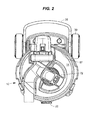
- Fig. 2 is a top plan view of the mulcher.
- Fig. 3 is a front elevation view of the mulcher.
- Fig. 4 is a left-side elevation view of the mulcher.
- Fig. 5 is a back elevation view of the mulcher.
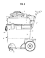
- Fig. 6 is a right-side elevation view of the mulcher.
- Fig. 7 is a bottom view of the mulcher.
- Fig. 8 is a partially exploded perspective view of the mulcher.
- Figs. 9 and 10 are further exploded perspective views of the mulcher.
- Fig. 11 is an exploded perspective view of the motor unit for the mulcher.
- Fig. 12a is a perspective view of blades in the shredder assembly.
- Fig. 12b is a top view of the blades seen in fig. 12a .
- Fig. 12c is a side view of the blades.
- Fig. 12d is a cross-sectional side view of the blades.
- Fig. 13 is a side sectional view of a portion of the mulcher.
- Figs. 14a and b are enlarged cross-sectional views through sections of the shredder assembly.
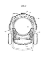
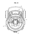
- Figs. 15-21 are views of the mulcher corresponding to figs. 1-8 but with the shredder assembly having been replaced by a basic head unit.
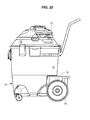
- Fig. 22 is an isometric view of another embodiment of a mulcher that incorporates the new invention.
- Fig. 23 is a top plan view of the mulcher of figure 22 .
- Fig. 24 is a front elevation view of that mulcher.
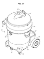
- Fig. 25 is a left-side elevation view of that mulcher.
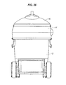
- Fig. 26 is a back elevation view of that mulcher.
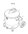
- Fig. 27 is a right-side elevation view of that mulcher.
- Fig. 28 is a bottom view of that mulcher.
- Figs. 29-35 are views that correspond with figures 22-28 , but show the mulcher with the shredder assembly removed.
- Fig. 36 is an exploded partial perspective view of the shredder assembly that is used with this embodiment of the invention, along with a conical filter.
- Fig. 37 is a cross-section view of the mulcher.
- Fig. 38 is an enlarged view of an electrical receptacle on the shredder assembly.
- Fig. 39 is a perspective view of a detachable blower that can be incorporated into a head unit in the mulcher.
- Fig. 40 is a side elevation view of an alternative arrangement of a detachable blower.
- the illustrated mulcher has three primary parts: a base unit 12, a shredder assembly 14 (seen in figs. 1-8 ), and a basic head unit 16 (seen in figs. 15-21 ). Each part will be described in turn.
- the illustrated base unit 12 has a tank wall 20, a closeable port 22, and an open top 24 (see figs. 8 and 9 ).
- the volume within the tank wall 20 defines a tank chamber (or storage reservoir) that is used to store collected dirt and debris, and can vary in size to meet consumer demands.
- the port can be used as an inlet during conventional vacuuming, or sealed with a cap (not shown) during mulching.
- the open top accommodates either the shredder assembly 14 (during mulching) or the head unit 16 (during conventional vacuuming).
- the base unit 12 can also include optional features like wheels or casters 30, a storage compartment 32, or a drain 34 for a wet/dry vacuum.
- a handle 35 can also be attached.
- the shredder assembly 14 (best seen in figs. 8-14 ) has a mulching inlet 36, a power module 37, and a lower rim 38.
- the mulching inlet can be used to collect leaves or other yard waste.
- the illustrated mulching inlet is part of a pathway that is relatively straight and has a relatively wide diameter. It has only two turns, each through an angle of less than 45°. Together with the 3 1 ⁇ 2" diameter of the inlet and its relatively short length (less than 10"), the straightness of this pathway provides a clog-resistant, easy- feeding inlet for leaves or yard waste. Other arrangements are possible, but it is preferred that the pathway to the power module be relatively wide and straight.
- the power module 37 cuts the material that is drawn in through the mulching inlet 36.
- the illustrated power module is powered by a motor 39, and preferably has a mulcher (or shredding) blade 40 that is optimized for shredding leaves, rather than for moving air.
- the shredding blade is mounted in front of and on the same shaft 41 as optional air impeller blades 42.
- the air impeller blades help to draw material to the shredding blade.
- the illustrated shredding blade is made of metal, and sits on top of and is supported by plastic impeller blades. This arrangement may help to prevent the shredding blade from deforming under centripetal force.
- the illustrated motor 39 is mounted between top and bottom covers 43a and 43b that fit against a motor plate 44.
- the shaft 41 extends through the motor plate, and a spacer 45 on the shaft provides clearance between the impeller blades 42 and the motor plate.
- a power switch 46 on the top cover enables a user to switch the motor on and off.
- the power module 37 fits onto a receptacle 48.
- the receptacle is in the shredder assembly 14.
- mounts 49 on the motor plate 44 enable the power module to be screwed onto the shredder assembly for ease of servicing. If the shredding blade 40 or the motor 39 would need to be repaired or replaced, the owner could remove the power module and return that assembly alone to the manufacturer or supplier for service.
- a safety switch 50 is mounted to the illustrated power module.
- a cooperating blade 51 (best seen in figs. 9 and 10 ) is mounted to a frame 52 within the shredder assembly 14. Contact between the blade and the safety switch is needed for power to pass through the switch.
- the blade contacts the safety switch, allowing power to pass through to the motor 39. Removing the power module from the receptacle breaks contact between the blade and the safety switch, disabling the motor.
- the frame is removed from the bottom of the shredder assembly, the blade loses contact with the safety switch and the power supply is shut off.
- the shredding blade 40 can spin within a mulcher housing 56 that is mounted within a cover 57 of the shredder assembly 14.
- the mulcher housing has a volute or similar arrangement that directs mulched material to a chamber outlet 58.
- Directional walls 59 are connected to the chamber outlet, and steer mulched debris and air that is ejected from the mulcher housing into a tangential path around an annular skirt wall 60 of the cover. While proceeding along that path, heavy debris falls into the storage reservoir in the base unit 12.
- a downwardly directed segment 61 at the end of a deflector 62 helps assure that lighter debris is also directed to the base unit.
- the illustrated shredder assembly 14 does not require a filter.
- the skirt wall 60, a lower wall 63 on the frame 52, a vertical rear wall 64 on the frame, and an annular inner wall 65 on the frame form a channel around the exterior of the directional walls 59. This channel leads to the sole exhaust port 66 on the shredder assembly, and forces large particles of debris in the unit to double back against the flow of air exiting the downstream end of the directional walls before they can reach the exhaust port.
- the port 22 on the base unit 12 can be sealed with a cap when the shredder assembly is in use. It is believed that the highspeed airflow exiting the directional walls will help to knock any large particles from the airflow heading in the opposite direction (toward the exhaust port), helping to reduce or eliminate the need for a separate filter.
- small holes are shown in the lower wall 63. These holes can help reduce pressure within the storage reservoir by permitting some air to exit the device without doubling back against the flow of air from the directional walls 59. The small size of the holes prevents large particles from taking this path.
- a solid wall (with no apertures) can also be used.
- the illustrated exhaust port 66 ( fig. 14 ) is positioned on the skirt wall 60 and is covered by an exhaust door 67 ( figs. 6 and 10 ).
- the exhaust door is hinged at the top so that it swings outwardly when the pressure inside the vacuum exceeds the outside pressure, allowing air to exhaust from the unit. When the unit is turned off, the weight of the door causes it to close.
- the lower rim 38 of the shredder assembly 14 is arranged so that it can be attached to the open top 24 of the base unit 12.
- Three latches 68 are provided on the illustrated base unit, and can be used to hold the shredder assembly to the base unit. Conventional latches are known.
- the latches 68 are arranged so that they can also hold the head unit 16 to the base unit 12. Although other arrangements are possible, providing the expensive parts of the latches on the base unit, rather than on both the shredder assembly 14 and on the head unit, may be preferred as a way to minimize cost.
- the opening of the lower rim 38 enables shredded leaves or yard waste cut by the shredding blade 40 to pass to the storage reservoir in the base unit.
- the open top 24 of the base unit also accommodates the head unit 16.
- a shredder power cord extends from the shredder assembly 14 and can be used to provide AC power to the shredder motor.
- An optional power receptacle 69 is electrically connected to the shredder power cord through a switch.
- the switch can be used to switch power coming in through the power cord to either the motor or, alternatively, to the receptacle. Providing a switch that directs power either to the motor or to the receptacle, but not to both simultaneously, helps to reduce the chance of overloading the circuit that the power cord is plugged into.
- a detachable blower 72 can be used with either the shredder assembly 14 or the head unit 16. When used with the head unit, the blower provides the vacuum used for conventional vacuuming, as explained in the 6,530,116 patent. When used with the shredder assembly, the blower can be used as an accessory tool. In that arrangement, a blower power cord for the blower can be plugged into the receptacle 68 on the shredder assembly, eliminating the need for the user to extend two separate cords to the primary power outlet.
- a caddy or supporting frame 74 on the shredder assembly ( fig. 9 ) accommodates the blower when it is not in use.
- FIG. 32-40 Another example of a shredder vacuum 10' is illustrated in figures 32-40 .
- This shredder vacuum 10' also has three primary parts: a base unit 12', a leaf shredder assembly 14', and a head unit 16'. Again, each part will be described in turn.
- the illustrated base unit 12' has a tank wall 20' ( fig. 38 ), a closeable port 22', and an open top 24'.
- the storage reservoir within the tank wall is also used to store collected products, and can vary in size to meet consumer demands.
- the port can be used as an inlet during conventional vacuuming, or sealed with a cap 26' during mulching.
- the open top accommodates either the shredder assembly 14' (during mulching) or the head unit 16' (during conventional vacuuming).
- the base unit 12' can also include optional features like wheels or casters 30', a storage compartment 32', or a drain 34'.
- the shredder assembly 14' has a mulching inlet 36', a shredding blade 40' ( fig. 38 ), and a lower rim 38'.
- the mulching inlet can be attached to a hose and is used to collect leaves.
- the shredding blade cuts the leaves that are drawn in through the inlet.
- the shredding blade is powered by a motor, and is preferably optimized for shredding leaves, rather than for moving air.
- the lower rim is arranged so that it can be attached to the open top 24' of the base unit 12', and has an opening 138' ( fig. 36 ) that enables the shredded leaves to move through a passage 139' from the shredding blade to the storage reservoir in the base unit.
- this shredder assembly 14' also has an upper opening 136'.
- the upper opening accommodates the head unit 16'.
- the shredder assembly 14' can also house an independent shredder motor for driving the shredding blade 40'.
- a shredder power cord running to the shredder motor can be used to provide AC power.
- the shredder assembly When the shredder assembly is provided with its own power cord, it can also be provided with a power receptacle 68', as seen in fig. 37 . That receptacle is electrically connected to the shredder power cord. Including a receptacle on the shredder assembly can provide the same advantage described above.
- the illustrated head unit 16' has a motor, an air impeller, a head inlet 140', and an exhaust port.
- the air impeller provides the motive force for drawing air, leaves, or other materials through the device.
- a conventional vacuum motor can be used to power the impeller.
- Relying on a separate impeller to provide the power for moving air through the device allows the shredding blade 40' to be specifically designed for shredding, rather than for moving air. Thus, a more efficient shredding blade can be used.
- the air impeller can be specifically designed to move air and not for shredding, as is the case in some household leaf vacuums.
- the head inlet 140' opens to the storage reservoir in the base unit 12', enabling the impeller to draw a vacuum in the reservoir through a passage 144' from the reservoir to the air impeller.
- the vacuum pulls leaves through the mulching inlet 36' during mulching operations and pulls dirt or debris through the port 22' in the base unit during vacuuming operations.
- the exhaust port allows air to escape from the unit.
- the head unit 16' can also include one or more filters.
- the illustrated filter 150' is a common paper filter mounted on a filter cage.
- the illustrated additional filter 152' is a conical filter that preliminarily filters the air before it reaches the paper filter.
- a flange 154' ( fig. 36 ) on the additional filter can be sized so that it can rest on an upper rim on either the open top 24' of the base unit 12' or on an upper opening 156' on the shredder assembly 14'.
- the illustrated head unit 16' includes a supporting frame 174' and a detachable blower 72', which houses the motor and the air impeller.
- the illustrated blower can be separated from the supporting frame so that the blower can be used separately.
- Non-detachable motor/impeller assemblies can also be used with the head unit.
- An impeller power cord can be used to provide AC power to the motor in the detachable blower 72'.
- the impeller power cord can be plugged into the receptacle on the shredder assembly to prevent the need for two separate cords to extend to user's primary power outlet.
- the illustrated embodiments provide differing options for mulching yard waste while being able to use a conventional wet/dry vacuum cleaner tank as the storage reservoir for the mulched material.
- the embodiment of figs. 1-21 utilizes air flow paths generated in the tank to minimize the amount of mulched material that passes out of the tank.
- the embodiment of figs. 22-38 utilizes conventional vacuum cleaner filtering to minimize the escape of mulched material. In each embodiment, much of the mulched material that is entrained in air flowing from the shredding blade is removed from air before the air passes out of the storage reservoir.
- a mulcher may comprise: an inlet for yard waste; a storage reservoir in a base unit; a shredding blade that is mounted in a unit that is separable from the base unit; a pathway that leads from the inlet to the shredding blade; an exhaust port that is in fluid communication with the shredding blade; and wherein shredded material is removed from air exiting the shredding blade before the air passes through the exhaust port.
- the shredding blade may be mounted in front of and on the same shaft as an impeller; the shredding blade may have a forwardly-projecting portion; and a back surface of the shredding blade may be supported by a forward portion of the impeller.
- the separable unit may have a vacuum assembly that carries an air impeller; and the shredding blade may be in a shedder assembly that is user-separable from the vacuum assembly.
- the shredding blade may be in a shredder assembly; the vacuum may have a separate vacuum assembly with an air impeller; and the base unit may have a part to which both the shredder assembly and the vacuum assembly can be alternately attached.
Abstract
Description
- This disclosure generally relates to products used to clean residential yards, and more particularly to products used to collect and dispose of fallen leaves or yard waste.
- Fallen leaves and yard waste are often collected and bagged or composted. Unless shredded, bagged leaves or yard waste can be bulky. Unfortunately, conventional shredders that are used to shred leaves and yard waster can be large and expensive. The large size can be inconvenient, particularly given that the product is generally used during only one season of the year.
- The applicants have developed a mulcher that has a removable shedder assembly that enables the product to be used for shredding leaves, yard waste, or other relatively lightweight materials. The shredder assembly can also be removed, enabling the vacuum to be used as a conventional utility vacuum. Because utility vacuums are used during all seasons, the product has more overall use.
-
Fig. 1 is an isometric view of one embodiment of a mulcher that incorporates the new invention. -
Fig. 2 is a top plan view of the mulcher. -
Fig. 3 is a front elevation view of the mulcher. -
Fig. 4 is a left-side elevation view of the mulcher. -
Fig. 5 is a back elevation view of the mulcher. -
Fig. 6 is a right-side elevation view of the mulcher. -
Fig. 7 is a bottom view of the mulcher. -
Fig. 8 is a partially exploded perspective view of the mulcher. -
Figs. 9 and10 are further exploded perspective views of the mulcher. -
Fig. 11 is an exploded perspective view of the motor unit for the mulcher. -
Fig. 12a is a perspective view of blades in the shredder assembly. -
Fig. 12b is a top view of the blades seen infig. 12a . -
Fig. 12c is a side view of the blades. -
Fig. 12d is a cross-sectional side view of the blades. -
Fig. 13 is a side sectional view of a portion of the mulcher. -
Figs. 14a andb are enlarged cross-sectional views through sections of the shredder assembly. -
Figs. 15-21 are views of the mulcher corresponding tofigs. 1-8 but with the shredder assembly having been replaced by a basic head unit. -
Fig. 22 is an isometric view of another embodiment of a mulcher that incorporates the new invention. -
Fig. 23 is a top plan view of the mulcher offigure 22 . -
Fig. 24 is a front elevation view of that mulcher. -
Fig. 25 is a left-side elevation view of that mulcher. -
Fig. 26 is a back elevation view of that mulcher. -
Fig. 27 is a right-side elevation view of that mulcher. -
Fig. 28 is a bottom view of that mulcher. -
Figs. 29-35 are views that correspond withfigures 22-28 , but show the mulcher with the shredder assembly removed. -
Fig. 36 is an exploded partial perspective view of the shredder assembly that is used with this embodiment of the invention, along with a conical filter. -
Fig. 37 is a cross-section view of the mulcher. -
Fig. 38 is an enlarged view of an electrical receptacle on the shredder assembly. -
Fig. 39 is a perspective view of a detachable blower that can be incorporated into a head unit in the mulcher. -
Fig. 40 is a side elevation view of an alternative arrangement of a detachable blower. - One example of a mulcher 10 that embodies the invention is illustrated in the figures. The illustrated mulcher has three primary parts: a
base unit 12, a shredder assembly 14 (seen infigs. 1-8 ), and a basic head unit 16 (seen infigs. 15-21 ). Each part will be described in turn. - The illustrated
base unit 12 has atank wall 20, acloseable port 22, and an open top 24 (seefigs. 8 and9 ). The volume within thetank wall 20 defines a tank chamber (or storage reservoir) that is used to store collected dirt and debris, and can vary in size to meet consumer demands. The port can be used as an inlet during conventional vacuuming, or sealed with a cap (not shown) during mulching. The open top accommodates either the shredder assembly 14 (during mulching) or the head unit 16 (during conventional vacuuming). - The
base unit 12 can also include optional features like wheels orcasters 30, astorage compartment 32, or adrain 34 for a wet/dry vacuum. Ahandle 35 can also be attached. - The shredder assembly 14 (best seen in
figs. 8-14 ) has amulching inlet 36, apower module 37, and alower rim 38. The mulching inlet can be used to collect leaves or other yard waste. The illustrated mulching inlet is part of a pathway that is relatively straight and has a relatively wide diameter. It has only two turns, each through an angle of less than 45°. Together with the 3 ½" diameter of the inlet and its relatively short length (less than 10"), the straightness of this pathway provides a clog-resistant, easy- feeding inlet for leaves or yard waste. Other arrangements are possible, but it is preferred that the pathway to the power module be relatively wide and straight. - The
power module 37 cuts the material that is drawn in through themulching inlet 36. As seen infig. 11 , the illustrated power module is powered by amotor 39, and preferably has a mulcher (or shredding)blade 40 that is optimized for shredding leaves, rather than for moving air. In the illustrated arrangement, the shredding blade is mounted in front of and on thesame shaft 41 as optionalair impeller blades 42. In this example, the air impeller blades help to draw material to the shredding blade. Infig. 12 , the illustrated shredding blade is made of metal, and sits on top of and is supported by plastic impeller blades. This arrangement may help to prevent the shredding blade from deforming under centripetal force. - As seen in
fig. 11 , the illustratedmotor 39 is mounted between top and bottom covers 43a and 43b that fit against amotor plate 44. Theshaft 41 extends through the motor plate, and aspacer 45 on the shaft provides clearance between theimpeller blades 42 and the motor plate. Apower switch 46 on the top cover enables a user to switch the motor on and off. - The
power module 37 fits onto areceptacle 48. As best seen infig. 8 , in this example the receptacle is in theshredder assembly 14. Although positioning the receptacle in the shredder assembly is generally preferred, in some instances it might be useful to mount the power module onto a receptacle in thebase unit 12. Here, mounts 49 on themotor plate 44 enable the power module to be screwed onto the shredder assembly for ease of servicing. If theshredding blade 40 or themotor 39 would need to be repaired or replaced, the owner could remove the power module and return that assembly alone to the manufacturer or supplier for service. - For safety, special care has been taken to minimize the risk of misuse of the
power module 37. As seen infigs. 11 and13 , asafety switch 50 is mounted to the illustrated power module. A cooperating blade 51 (best seen infigs. 9 and10 ) is mounted to aframe 52 within theshredder assembly 14. Contact between the blade and the safety switch is needed for power to pass through the switch. When the power module is seated onto thereceptacle 48, the blade contacts the safety switch, allowing power to pass through to themotor 39. Removing the power module from the receptacle breaks contact between the blade and the safety switch, disabling the motor. Similarly, if the frame is removed from the bottom of the shredder assembly, the blade loses contact with the safety switch and the power supply is shut off. - As suggested in
figs. 9 and10 , when thepower module 37 is seated onto thereceptacle 48, theshredding blade 40 can spin within amulcher housing 56 that is mounted within acover 57 of theshredder assembly 14. The mulcher housing has a volute or similar arrangement that directs mulched material to achamber outlet 58.Directional walls 59 are connected to the chamber outlet, and steer mulched debris and air that is ejected from the mulcher housing into a tangential path around anannular skirt wall 60 of the cover. While proceeding along that path, heavy debris falls into the storage reservoir in thebase unit 12. A downwardly directedsegment 61 at the end of adeflector 62 helps assure that lighter debris is also directed to the base unit. - The illustrated
shredder assembly 14 does not require a filter. As can be understood fromfig. 14 , theskirt wall 60, alower wall 63 on theframe 52, a verticalrear wall 64 on the frame, and an annularinner wall 65 on the frame form a channel around the exterior of thedirectional walls 59. This channel leads to thesole exhaust port 66 on the shredder assembly, and forces large particles of debris in the unit to double back against the flow of air exiting the downstream end of the directional walls before they can reach the exhaust port. (As mentioned previously, theport 22 on thebase unit 12 can be sealed with a cap when the shredder assembly is in use.) It is believed that the highspeed airflow exiting the directional walls will help to knock any large particles from the airflow heading in the opposite direction (toward the exhaust port), helping to reduce or eliminate the need for a separate filter. - In the illustrated device, small holes are shown in the
lower wall 63. These holes can help reduce pressure within the storage reservoir by permitting some air to exit the device without doubling back against the flow of air from thedirectional walls 59. The small size of the holes prevents large particles from taking this path. A solid wall (with no apertures) can also be used. - The illustrated exhaust port 66 (
fig. 14 ) is positioned on theskirt wall 60 and is covered by an exhaust door 67 (figs. 6 and10 ). The exhaust door is hinged at the top so that it swings outwardly when the pressure inside the vacuum exceeds the outside pressure, allowing air to exhaust from the unit. When the unit is turned off, the weight of the door causes it to close. - The
lower rim 38 of theshredder assembly 14 is arranged so that it can be attached to theopen top 24 of thebase unit 12. Three latches 68 are provided on the illustrated base unit, and can be used to hold the shredder assembly to the base unit. Conventional latches are known. - The
latches 68 are arranged so that they can also hold thehead unit 16 to thebase unit 12. Although other arrangements are possible, providing the expensive parts of the latches on the base unit, rather than on both theshredder assembly 14 and on the head unit, may be preferred as a way to minimize cost. - When the
shredder assembly 14 is attached to thebase unit 12, the opening of thelower rim 38 enables shredded leaves or yard waste cut by theshredding blade 40 to pass to the storage reservoir in the base unit. When the shredder assembly is removed from the base unit, theopen top 24 of the base unit also accommodates thehead unit 16. - As seen in
figs. 15-21 , mounting thehead unit 16 on thebase unit 12 creates a unit that can operate as a conventional utility vacuum cleaner. Comparable arrangements are described inU.S. patent no. 6,530,116 . The disclosure of that patent is incorporated by reference into this disclosure. - In the illustrated device, a shredder power cord (not shown) extends from the
shredder assembly 14 and can be used to provide AC power to the shredder motor. Anoptional power receptacle 69, best seen infig. 11 , is electrically connected to the shredder power cord through a switch. The switch can be used to switch power coming in through the power cord to either the motor or, alternatively, to the receptacle. Providing a switch that directs power either to the motor or to the receptacle, but not to both simultaneously, helps to reduce the chance of overloading the circuit that the power cord is plugged into. - A
detachable blower 72 can be used with either theshredder assembly 14 or thehead unit 16. When used with the head unit, the blower provides the vacuum used for conventional vacuuming, as explained in the 6,530,116 patent. When used with the shredder assembly, the blower can be used as an accessory tool. In that arrangement, a blower power cord for the blower can be plugged into thereceptacle 68 on the shredder assembly, eliminating the need for the user to extend two separate cords to the primary power outlet. A caddy or supportingframe 74 on the shredder assembly (fig. 9 ) accommodates the blower when it is not in use. - Another example of a shredder vacuum 10' is illustrated in
figures 32-40 . This shredder vacuum 10' also has three primary parts: a base unit 12', aleaf shredder assembly 14', and a head unit 16'. Again, each part will be described in turn. - The illustrated base unit 12' has a tank wall 20' (
fig. 38 ), a closeable port 22', and an open top 24'. The storage reservoir within the tank wall is also used to store collected products, and can vary in size to meet consumer demands. The port can be used as an inlet during conventional vacuuming, or sealed with a cap 26' during mulching. The open top accommodates either theshredder assembly 14' (during mulching) or the head unit 16' (during conventional vacuuming). - The base unit 12' can also include optional features like wheels or casters 30', a storage compartment 32', or a drain 34'.
- The
shredder assembly 14' has a mulching inlet 36', a shredding blade 40' (fig. 38 ), and a lower rim 38'. The mulching inlet can be attached to a hose and is used to collect leaves. The shredding blade cuts the leaves that are drawn in through the inlet. The shredding blade is powered by a motor, and is preferably optimized for shredding leaves, rather than for moving air. The lower rim is arranged so that it can be attached to the open top 24' of the base unit 12', and has an opening 138' (fig. 36 ) that enables the shredded leaves to move through a passage 139' from the shredding blade to the storage reservoir in the base unit. - Unlike in the other embodiments, this
shredder assembly 14' also has an upper opening 136'. The upper opening accommodates the head unit 16'. - The
shredder assembly 14' can also house an independent shredder motor for driving the shredding blade 40'. A shredder power cord running to the shredder motor can be used to provide AC power. When the shredder assembly is provided with its own power cord, it can also be provided with a power receptacle 68', as seen infig. 37 . That receptacle is electrically connected to the shredder power cord. Including a receptacle on the shredder assembly can provide the same advantage described above. - The illustrated head unit 16' has a motor, an air impeller, a head inlet 140', and an exhaust port. The air impeller provides the motive force for drawing air, leaves, or other materials through the device. A conventional vacuum motor can be used to power the impeller. Relying on a separate impeller to provide the power for moving air through the device allows the shredding blade 40' to be specifically designed for shredding, rather than for moving air. Thus, a more efficient shredding blade can be used. Similarly, the air impeller can be specifically designed to move air and not for shredding, as is the case in some household leaf vacuums.
- The head inlet 140' opens to the storage reservoir in the base unit 12', enabling the impeller to draw a vacuum in the reservoir through a passage 144' from the reservoir to the air impeller. The vacuum pulls leaves through the mulching inlet 36' during mulching operations and pulls dirt or debris through the port 22' in the base unit during vacuuming operations. The exhaust port allows air to escape from the unit.
- The head unit 16' can also include one or more filters. The illustrated filter 150' is a common paper filter mounted on a filter cage. The illustrated additional filter 152' is a conical filter that preliminarily filters the air before it reaches the paper filter. A flange 154' (
fig. 36 ) on the additional filter can be sized so that it can rest on an upper rim on either the open top 24' of the base unit 12' or on an upper opening 156' on theshredder assembly 14'. - As seen in
fig. 38 , the illustrated head unit 16' includes a supporting frame 174' and a detachable blower 72', which houses the motor and the air impeller. The illustrated blower can be separated from the supporting frame so that the blower can be used separately. Non-detachable motor/impeller assemblies can also be used with the head unit. - An impeller power cord can be used to provide AC power to the motor in the detachable blower 72'. When the
shredder assembly 14' is provided with a separate shredder power cord and receptacle, the impeller power cord can be plugged into the receptacle on the shredder assembly to prevent the need for two separate cords to extend to user's primary power outlet. - The illustrated embodiments provide differing options for mulching yard waste while being able to use a conventional wet/dry vacuum cleaner tank as the storage reservoir for the mulched material. The embodiment of
figs. 1-21 utilizes air flow paths generated in the tank to minimize the amount of mulched material that passes out of the tank. The embodiment offigs. 22-38 utilizes conventional vacuum cleaner filtering to minimize the escape of mulched material. In each embodiment, much of the mulched material that is entrained in air flowing from the shredding blade is removed from air before the air passes out of the storage reservoir. - A mulcher according to the invention may comprise: an inlet for yard waste; a storage reservoir in a base unit; a shredding blade that is mounted in a unit that is separable from the base unit; a pathway that leads from the inlet to the shredding blade; an exhaust port that is in fluid communication with the shredding blade; and wherein shredded material is removed from air exiting the shredding blade before the air passes through the exhaust port.
- In an embodiment, the shredding blade may be mounted in front of and on the same shaft as an impeller; the shredding blade may have a forwardly-projecting portion; and a back surface of the shredding blade may be supported by a forward portion of the impeller.
- In an embodiment, the separable unit may have a vacuum assembly that carries an air impeller; and the shredding blade may be in a shedder assembly that is user-separable from the vacuum assembly.
- In an embodiment, the shredding blade may be in a shredder assembly; the vacuum may have a separate vacuum assembly with an air impeller; and the base unit may have a part to which both the shredder assembly and the vacuum assembly can be alternately attached.
- This disclosure describes specific applications of the invention, and is intended to be illustrative only. It will be apparent to those of ordinary skill in the art that changes, additions, and deletions may be made to the disclosed embodiments without departing from the scope of the disclosure. The scope of the invention is set out in the following claims.
Claims (14)
- A mulcher (10') comprising:an inlet (36') for yard waste;a shredding blade (40');a pathway from the inlet (36') to the shredding blade (40');a storage reservoir beneath the shredding blade (40');an exhaust port (66) in fluid communication with the shredding blade (40'); anda filter (150') interposed between the shredding blade (40') and the exhaust port (66).
- A mulcher (10) comprising:an inlet (36) for yard waste;a shredding blade (40);a pathway from the inlet (36) to the shredding blade (40);a storage reservoir beneath the shredding blade (40);an exhaust port (66) in fluid communication with the shredding blade (40); anda wall (59) that is interposed between the shredding blade (40) and the exhaust port (66) and forces all shredded material exiting the shredding blade (40) to change direction before reaching the exhaust port (66).
- A mulcher (10) as recited in claim 2, in which:the wall (59) is part of a tube;the vacuum also has a channel (60, 63, 64, 65) adjacent the tube; andair flows though the tube in one direction, and through the channel (60, 63, 64, 65) in an opposite direction.
- A mulcher (10) as recited in claim 2, in which:the wall (59) is part of a tube;the vacuum also has a channel (60, 63, 64, 65) that is adjacent to and at least partially surrounds the tube; andair flows though the tube in one direction, and through the channel (60, 63, 64, 65) in an opposite direction.
- A shredder assembly (14; 14') for a utility vacuum that has (a) a base unit (12; 2') with an open top (24; 24') and (b) a user-separable head unit (16; 16') that attaches to the open top (24; 24') of the base unit (12; 12'), the shredder assembly (14; 14') comprising:an inlet (36; 36') for yard waste;a shredding blade (40; 40');a pathway from the inlet (36; 36') to the shredding blade (40; 40'); anda lower rim (38; 38') that attaches to the open top (24; 24') of the base unit (12; 12') of the utility vacuum and has an opening that enables shredded material to pass from the shredding blade (40; 40') to the base unit (12; 12') when the shredder assembly (14; 14') is attached to the base unit (12; 12').
- A shredder assembly (14') as recited in claim 5, in which the assembly also comprises:an upper opening (136') that attaches to an open bottom of a head unit (16') for the utility vacuum; anda passage that enables air to pass from the base unit (12') to an impeller in the head unit (16') when the shredder assembly (14') is attached to the base unit (12') and to the head unit (16').
- A shredder assembly (14; 14') as recited in claim 5, in which the assembly also comprises:a shredder power cord; andan electrical receptacle (69; 68').
- A shredder assembly (14) as recited in claim 5, in which the assembly also comprises a detachable power module (37) that houses both the shredding blade (40) and a shredder motor (39).
- A shredder assembly (14) as recited in claim 5, in which the assembly also comprises:a detachable power module (37); anda safety switch (50) that disables the power module (37) when the power module (37) is detached from the shredder assembly (14).
- A shredder assembly (14') as recited in claim 5, in which the assembly also comprises:an independent shredder motor that drives the shredding blade (40');a shredder power cord that runs from the shredder motor to an AC plug; anda power receptacle (68').
- A shredder assembly (14) as recited in claim 5, in which the assembly also comprises:a power receptacle (69);a shredder motor (39); anda switch that alternately switches power to either the shredder motor (39) or to the power receptacle (69), but not to both simultaneously.
- A mulcher (10; 10') comprising:an inlet (36; 36') for yard waste;a shredding blade (40; 40') in a shredder assembly (14; 14');a pathway from the inlet (36; 36') to the shredding blade (40; 40');a storage reservoir beneath the shredding blade (40; 40');an exhaust port (66) in fluid communication with the shredding blade (40; 40'); andan air moving unit that is user-separable from the shredder assembly (14; 14') and has an impeller.
- A mulcher (10; 10') as recited in claim 12, in which the mulcher also comprises:a blower (72; 72') that has a blower power cord, houses an air impeller, and is user- separable from a supporting frame (74; 174');a separate shredder power cord; andan electrical receptacle (69; 68').
- A mulcher (10; 10') as recited in claim 12, in which:the storage reservoir is in a base unit (12; 12'); andthe base unit (12; 12') also has a separate, closable port (22; 22').
Applications Claiming Priority (3)
| Application Number | Priority Date | Filing Date | Title |
|---|---|---|---|
| US84670006P | 2006-09-22 | 2006-09-22 | |
| US95754907P | 2007-08-23 | 2007-08-23 | |
| EP07873330A EP2063699B1 (en) | 2006-09-22 | 2007-09-22 | Leaf shredder vacuum |
Related Parent Applications (1)
| Application Number | Title | Priority Date | Filing Date |
|---|---|---|---|
| EP07873330.0 Division | 2007-09-22 |
Publications (3)
| Publication Number | Publication Date |
|---|---|
| EP2258246A2 true EP2258246A2 (en) | 2010-12-08 |
| EP2258246A3 EP2258246A3 (en) | 2011-03-23 |
| EP2258246B1 EP2258246B1 (en) | 2013-06-26 |
Family
ID=39789086
Family Applications (2)
| Application Number | Title | Priority Date | Filing Date |
|---|---|---|---|
| EP10177336.4A Expired - Fee Related EP2258246B1 (en) | 2006-09-22 | 2007-09-22 | Mulcher |
| EP07873330A Expired - Fee Related EP2063699B1 (en) | 2006-09-22 | 2007-09-22 | Leaf shredder vacuum |
Family Applications After (1)
| Application Number | Title | Priority Date | Filing Date |
|---|---|---|---|
| EP07873330A Expired - Fee Related EP2063699B1 (en) | 2006-09-22 | 2007-09-22 | Leaf shredder vacuum |
Country Status (9)
| Country | Link |
|---|---|
| US (1) | US7654480B2 (en) |
| EP (2) | EP2258246B1 (en) |
| AU (1) | AU2007350149B2 (en) |
| CA (1) | CA2653699C (en) |
| DE (1) | DE602007010795D1 (en) |
| DK (1) | DK2063699T3 (en) |
| HK (1) | HK1126949A1 (en) |
| MX (1) | MX2008016122A (en) |
| WO (1) | WO2008117110A2 (en) |
Families Citing this family (39)
| Publication number | Priority date | Publication date | Assignee | Title |
|---|---|---|---|---|
| DE102008030749B4 (en) * | 2008-06-27 | 2019-03-07 | Hosokawa Alpine Ag | Grinding device with mill as a built-in module |
| US8122697B1 (en) * | 2009-03-27 | 2012-02-28 | Leaf Harvest, LLC | Leaf cutting apparatus |
| US9826688B2 (en) * | 2009-11-06 | 2017-11-28 | Shop Vac Corporation | Vacuum device with positive pressure tank |
| US20110247170A1 (en) * | 2010-04-13 | 2011-10-13 | Jones Christopher W S | Trash Bin Vacuum Adapter Apparatus |
| US8602334B2 (en) | 2010-12-06 | 2013-12-10 | The Toro Company | Debris vacuum with supplemental debris shearing surface |
| US8596565B2 (en) | 2011-05-18 | 2013-12-03 | 105766 Canada Inc. | Leaf stripper |
| CN102615091A (en) * | 2012-04-09 | 2012-08-01 | 南京工业职业技术学院 | Leaf collecting, smashing, recovering and recycling device |
| USD746100S1 (en) | 2014-08-25 | 2015-12-29 | Emerson Electric Co. | Food waste disposer |
| USD753433S1 (en) | 2015-01-12 | 2016-04-12 | Emerson Electric Co. | Food waste disposer |
| USD753432S1 (en) | 2015-01-12 | 2016-04-12 | Emerson Electric Co. | Food waste disposer |
| USD759423S1 (en) | 2015-01-12 | 2016-06-21 | Emerson Electric Co. | Food waste disposer |
| TWI653962B (en) | 2016-02-29 | 2019-03-21 | Lg電子股份有限公司 | Vacuum cleaner |
| TWI637715B (en) * | 2016-02-29 | 2018-10-11 | Lg電子股份有限公司 | Vacuum cleaner |
| WO2017150816A1 (en) | 2016-02-29 | 2017-09-08 | 엘지전자 주식회사 | Vacuum cleaner |
| TWI636758B (en) | 2016-02-29 | 2018-10-01 | Lg電子股份有限公司 | Vacuum cleaner |
| TWI664943B (en) | 2016-02-29 | 2019-07-11 | Lg電子股份有限公司 | Vacuum cleaner |
| DE112017000532B4 (en) | 2016-02-29 | 2023-11-09 | Lg Electronics Inc. | Vacuum cleaner |
| TWI664944B (en) * | 2016-02-29 | 2019-07-11 | Lg電子股份有限公司 | Vacuum cleaner |
| TWI643596B (en) | 2016-02-29 | 2018-12-11 | Lg電子股份有限公司 | Vacuum cleaner |
| TWI643597B (en) | 2016-02-29 | 2018-12-11 | Lg電子股份有限公司 | Vacuum cleaner |
| WO2017150874A1 (en) | 2016-02-29 | 2017-09-08 | 엘지전자 주식회사 | Vacuum cleaner |
| TWI641353B (en) * | 2016-02-29 | 2018-11-21 | Lg電子股份有限公司 | Vacuum cleaner |
| DE202017000985U1 (en) * | 2016-02-29 | 2017-05-29 | Lg Electronics Inc. | vacuum cleaner |
| TWI637718B (en) | 2016-02-29 | 2018-10-11 | Lg電子股份有限公司 | Vacuum cleaner |
| DE202017000984U1 (en) | 2016-02-29 | 2017-05-29 | Lg Electronics Inc. | vacuum cleaner |
| WO2017150862A1 (en) | 2016-02-29 | 2017-09-08 | 엘지전자 주식회사 | Vacuum cleaner |
| US10299647B2 (en) | 2016-05-03 | 2019-05-28 | Lg Electronics Inc. | Vacuum cleaner |
| US10299645B2 (en) | 2016-05-03 | 2019-05-28 | Lg Electronics Inc. | Vacuum cleaner |
| US10299646B2 (en) | 2016-05-03 | 2019-05-28 | Lg Electronics Inc. | Vacuum cleaner |
| KR101822944B1 (en) | 2016-05-03 | 2018-01-29 | 엘지전자 주식회사 | Vacuum cleaner |
| KR101852435B1 (en) | 2016-05-03 | 2018-04-26 | 엘지전자 주식회사 | Vacuum cleaner |
| US10271702B2 (en) | 2016-05-03 | 2019-04-30 | Lg Electronics Inc. | Vacuum cleaner |
| DE202017002619U1 (en) | 2016-05-20 | 2017-08-04 | Lg Electronics Inc. | vacuum cleaner |
| USD822426S1 (en) | 2016-06-27 | 2018-07-10 | Emerson Electric Co. | Food waste disposer |
| US10869586B2 (en) | 2016-11-17 | 2020-12-22 | Karcher North America, Inc. | Portable vacuum and related accessories |
| CN108636543A (en) * | 2018-04-25 | 2018-10-12 | 安徽沃屹智能装备有限公司 | A kind of switch board installation Special cleaning tool |
| CN109328707B (en) * | 2018-10-19 | 2021-05-28 | 嘉善顺源金属制品有限公司 | Can collect trimming means of abandonment branch and leaf |
| CN112221628B (en) * | 2020-09-08 | 2022-03-18 | 田庆华 | Automatic pulping and cleaning process for kitchen garbage |
| GB2612613A (en) * | 2021-11-05 | 2023-05-10 | Robert Frohlich Pierre | Stem and branch cutter |
Citations (1)
| Publication number | Priority date | Publication date | Assignee | Title |
|---|---|---|---|---|
| US6530116B2 (en) | 2001-02-13 | 2003-03-11 | Shop Vac Corporation | Vacuum cleaner with muffled detachable blower exhaust |
Family Cites Families (19)
| Publication number | Priority date | Publication date | Assignee | Title |
|---|---|---|---|---|
| US4143823A (en) * | 1977-09-06 | 1979-03-13 | Judson Jr Carl | Hammermills |
| DE3623120A1 (en) * | 1986-07-09 | 1988-01-21 | Ernst Maurer | Universal leaf disintegrating unit |
| JPH01223205A (en) | 1988-03-02 | 1989-09-06 | Suiden:Kk | Suction type cleaner for cleaning fallen leaves |
| US5085375A (en) * | 1990-12-21 | 1992-02-04 | Cotter & Company | Leaf mulcher |
| GB9108689D0 (en) * | 1991-04-23 | 1991-06-12 | Clarke Robert D | Portable tool |
| US5245726A (en) | 1991-07-22 | 1993-09-21 | Rote Scott J | Apparatus for picking up and shredding natural yard waste |
| US5294063A (en) | 1991-11-04 | 1994-03-15 | Echo, Incorporated | Debris vacuum selectively usable as a hand-held and wheeled unit |
| US5340036A (en) | 1993-05-19 | 1994-08-23 | Emerson Electric Co. | Dry waste grinder |
| JP3128181B2 (en) | 1994-07-04 | 2001-01-29 | 株式会社共立 | Vacuum cleaner |
| US5485715A (en) * | 1994-11-14 | 1996-01-23 | Breeden; Harlan | Grass and leaf eradicator |
| AU6596496A (en) | 1995-07-28 | 1997-02-26 | Wci Outdoor Products, Inc. | Portable lawn and garden mulching vacuum |
| DE19601594C2 (en) * | 1996-01-18 | 1998-07-23 | Fritsch Gmbh | Method and device for comminuting materials, in particular for sample preparation for analysis |
| US5692262A (en) | 1996-01-22 | 1997-12-02 | Haupt; David J. | Mulching impeller for lawn and garden mulching blower-vacuum |
| DE19608376C2 (en) | 1996-03-05 | 2002-10-10 | Multi Cad Gmbh | cradle |
| DE19609569A1 (en) | 1996-03-12 | 1997-09-18 | Adlus Gmbh & Co | Blower and suction device, in particular suction chopper for collecting and crushing leaves and the like |
| WO1997044998A1 (en) | 1996-05-29 | 1997-12-04 | International Retail Direct Promotions, Inc. | Apparatus for converting string trimmer to mulcher and vacuum |
| US5988540A (en) * | 1998-08-26 | 1999-11-23 | Pugh; Terrance | Comminuting and distributing device for recycling yard waste |
| FR2812312B1 (en) | 2000-07-25 | 2003-01-24 | Sert | SANITARY CRUSHER |
| US6629818B2 (en) | 2001-02-09 | 2003-10-07 | The Toro Company | Impeller for use with portable blower/vacuums |
-
2007
- 2007-09-22 MX MX2008016122A patent/MX2008016122A/en not_active Application Discontinuation
- 2007-09-22 CA CA2653699A patent/CA2653699C/en not_active Expired - Fee Related
- 2007-09-22 DK DK07873330.0T patent/DK2063699T3/en active
- 2007-09-22 AU AU2007350149A patent/AU2007350149B2/en not_active Ceased
- 2007-09-22 EP EP10177336.4A patent/EP2258246B1/en not_active Expired - Fee Related
- 2007-09-22 WO PCT/IB2007/004399 patent/WO2008117110A2/en active Application Filing
- 2007-09-22 US US11/859,760 patent/US7654480B2/en active Active
- 2007-09-22 DE DE602007010795T patent/DE602007010795D1/en active Active
- 2007-09-22 EP EP07873330A patent/EP2063699B1/en not_active Expired - Fee Related
-
2009
- 2009-06-24 HK HK09105696.7A patent/HK1126949A1/en not_active IP Right Cessation
Patent Citations (1)
| Publication number | Priority date | Publication date | Assignee | Title |
|---|---|---|---|---|
| US6530116B2 (en) | 2001-02-13 | 2003-03-11 | Shop Vac Corporation | Vacuum cleaner with muffled detachable blower exhaust |
Also Published As
| Publication number | Publication date |
|---|---|
| EP2063699B1 (en) | 2010-11-24 |
| CA2653699A1 (en) | 2008-10-02 |
| CA2653699C (en) | 2014-06-10 |
| US20080072396A1 (en) | 2008-03-27 |
| EP2063699A2 (en) | 2009-06-03 |
| EP2258246B1 (en) | 2013-06-26 |
| MX2008016122A (en) | 2009-04-15 |
| WO2008117110A3 (en) | 2009-04-30 |
| DE602007010795D1 (en) | 2011-01-05 |
| HK1126949A1 (en) | 2009-09-18 |
| AU2007350149A1 (en) | 2008-10-02 |
| WO2008117110A2 (en) | 2008-10-02 |
| DK2063699T3 (en) | 2011-03-14 |
| EP2258246A3 (en) | 2011-03-23 |
| US7654480B2 (en) | 2010-02-02 |
| AU2007350149B2 (en) | 2011-02-24 |
Similar Documents
| Publication | Publication Date | Title |
|---|---|---|
| EP2258246B1 (en) | Mulcher | |
| US5231827A (en) | Lawn and garden chipper shredder vacuum apparatus | |
| CN106049326B (en) | Suction and blowing device | |
| EP2201881B1 (en) | Hand held vacuum cleaner | |
| JP3260271B2 (en) | Waste collection machine | |
| US5381970A (en) | Combination chipper/shredder and vacuum apparatus for lawns and gardens | |
| EP2223644B1 (en) | Motor, fan and filter arrangement for a vacuum cleaner | |
| US10231591B2 (en) | Dust container | |
| EP3082538A1 (en) | Autonomous cleaner | |
| EP1512319B1 (en) | Grass mower | |
| CN104509308B (en) | Intelligent mower | |
| CN219068764U (en) | Control box and garden tool | |
| CN101600382A (en) | Leaf shredder vacuum | |
| CN201051790Y (en) | Mower with dust absorption function | |
| US20140130327A1 (en) | Wet/Dry Vacuum Cleaner Leaf Mulcher | |
| JP3224651U (en) | Vacuum cleaner and smoke reduction device | |
| CN217885904U (en) | Sewage treatment device, base station and cleaning system | |
| CN209899254U (en) | Portable hand push dust collector of area linkage | |
| CN215087865U (en) | Hand-push pure-suction type electric leaf crushing vehicle | |
| EP1286582B1 (en) | Impeller assembly for yard vacuum unit | |
| CN219132385U (en) | Negative pressure split rotary shaver | |
| JPS5835315Y2 (en) | Kitchen waste processing machine | |
| CN115717373A (en) | Leaf-sucking type leaf-crushing machine | |
| CN2339370Y (en) | Improved hand sawing-machine | |
| CN112673802A (en) | Grass cutter |
Legal Events
| Date | Code | Title | Description |
|---|---|---|---|
| PUAI | Public reference made under article 153(3) epc to a published international application that has entered the european phase |
Free format text: ORIGINAL CODE: 0009012 |
|
| AC | Divisional application: reference to earlier application |
Ref document number: 2063699 Country of ref document: EP Kind code of ref document: P |
|
| AK | Designated contracting states |
Kind code of ref document: A2 Designated state(s): DE DK FR GB IT SE |
|
| RIN1 | Information on inventor provided before grant (corrected) |
Inventor name: BUSS, RANDY, L. Inventor name: CREVLING, ROBERT, LENT, JR. Inventor name: BAER, MARK, E. Inventor name: GOTSCHALL, JASON |
|
| PUAL | Search report despatched |
Free format text: ORIGINAL CODE: 0009013 |
|
| AK | Designated contracting states |
Kind code of ref document: A3 Designated state(s): DE DK FR GB IT SE |
|
| 17P | Request for examination filed |
Effective date: 20110923 |
|
| 17Q | First examination report despatched |
Effective date: 20120329 |
|
| REG | Reference to a national code |
Ref country code: DE Ref legal event code: R079 Ref document number: 602007031337 Country of ref document: DE Free format text: PREVIOUS MAIN CLASS: A47L0007000000 Ipc: A01G0003000000 |
|
| GRAP | Despatch of communication of intention to grant a patent |
Free format text: ORIGINAL CODE: EPIDOSNIGR1 |
|
| RIC1 | Information provided on ipc code assigned before grant |
Ipc: B02C 18/10 20060101ALI20130213BHEP Ipc: B02C 18/16 20060101ALI20130213BHEP Ipc: A01G 3/00 20060101AFI20130213BHEP |
|
| GRAS | Grant fee paid |
Free format text: ORIGINAL CODE: EPIDOSNIGR3 |
|
| GRAA | (expected) grant |
Free format text: ORIGINAL CODE: 0009210 |
|
| RIN1 | Information on inventor provided before grant (corrected) |
Inventor name: BAER, MARK, E. Inventor name: GOTSCHALL, JASON Inventor name: BUSS, RANDY, L. Inventor name: CREVLING, ROBERT, LENT, JR. |
|
| AC | Divisional application: reference to earlier application |
Ref document number: 2063699 Country of ref document: EP Kind code of ref document: P |
|
| AK | Designated contracting states |
Kind code of ref document: B1 Designated state(s): DE DK FR GB IT SE |
|
| REG | Reference to a national code |
Ref country code: GB Ref legal event code: FG4D |
|
| REG | Reference to a national code |
Ref country code: DE Ref legal event code: R096 Ref document number: 602007031337 Country of ref document: DE Effective date: 20130822 |
|
| PG25 | Lapsed in a contracting state [announced via postgrant information from national office to epo] |
Ref country code: SE Free format text: LAPSE BECAUSE OF FAILURE TO SUBMIT A TRANSLATION OF THE DESCRIPTION OR TO PAY THE FEE WITHIN THE PRESCRIBED TIME-LIMIT Effective date: 20130626 |
|
| PG25 | Lapsed in a contracting state [announced via postgrant information from national office to epo] |
Ref country code: DK Free format text: LAPSE BECAUSE OF FAILURE TO SUBMIT A TRANSLATION OF THE DESCRIPTION OR TO PAY THE FEE WITHIN THE PRESCRIBED TIME-LIMIT Effective date: 20130626 |
|
| PLBE | No opposition filed within time limit |
Free format text: ORIGINAL CODE: 0009261 |
|
| STAA | Information on the status of an ep patent application or granted ep patent |
Free format text: STATUS: NO OPPOSITION FILED WITHIN TIME LIMIT |
|
| PG25 | Lapsed in a contracting state [announced via postgrant information from national office to epo] |
Ref country code: IT Free format text: LAPSE BECAUSE OF FAILURE TO SUBMIT A TRANSLATION OF THE DESCRIPTION OR TO PAY THE FEE WITHIN THE PRESCRIBED TIME-LIMIT Effective date: 20130626 |
|
| 26N | No opposition filed |
Effective date: 20140327 |
|
| REG | Reference to a national code |
Ref country code: DE Ref legal event code: R097 Ref document number: 602007031337 Country of ref document: DE Effective date: 20140327 |
|
| REG | Reference to a national code |
Ref country code: FR Ref legal event code: PLFP Year of fee payment: 9 |
|
| PGFP | Annual fee paid to national office [announced via postgrant information from national office to epo] |
Ref country code: GB Payment date: 20150916 Year of fee payment: 9 Ref country code: DE Payment date: 20150916 Year of fee payment: 9 |
|
| PGFP | Annual fee paid to national office [announced via postgrant information from national office to epo] |
Ref country code: FR Payment date: 20150825 Year of fee payment: 9 |
|
| REG | Reference to a national code |
Ref country code: DE Ref legal event code: R119 Ref document number: 602007031337 Country of ref document: DE |
|
| GBPC | Gb: european patent ceased through non-payment of renewal fee |
Effective date: 20160922 |
|
| REG | Reference to a national code |
Ref country code: FR Ref legal event code: ST Effective date: 20170531 |
|
| PG25 | Lapsed in a contracting state [announced via postgrant information from national office to epo] |
Ref country code: GB Free format text: LAPSE BECAUSE OF NON-PAYMENT OF DUE FEES Effective date: 20160922 Ref country code: FR Free format text: LAPSE BECAUSE OF NON-PAYMENT OF DUE FEES Effective date: 20160930 Ref country code: DE Free format text: LAPSE BECAUSE OF NON-PAYMENT OF DUE FEES Effective date: 20170401 |