EP2256641A2 - Echtzeit-Planung von linearen Modellen zur Steuerung und Schätzung - Google Patents
Echtzeit-Planung von linearen Modellen zur Steuerung und Schätzung Download PDFInfo
- Publication number
- EP2256641A2 EP2256641A2 EP10156974A EP10156974A EP2256641A2 EP 2256641 A2 EP2256641 A2 EP 2256641A2 EP 10156974 A EP10156974 A EP 10156974A EP 10156974 A EP10156974 A EP 10156974A EP 2256641 A2 EP2256641 A2 EP 2256641A2
- Authority
- EP
- European Patent Office
- Prior art keywords
- linear
- models
- engine
- scheduling
- offline
- Prior art date
- Legal status (The legal status is an assumption and is not a legal conclusion. Google has not performed a legal analysis and makes no representation as to the accuracy of the status listed.)
- Withdrawn
Links
- 238000000034 method Methods 0.000 claims abstract description 114
- 238000005094 computer simulation Methods 0.000 claims abstract description 10
- 230000004044 response Effects 0.000 claims description 22
- 238000013459 approach Methods 0.000 claims description 17
- 238000001914 filtration Methods 0.000 claims description 8
- 238000012360 testing method Methods 0.000 description 13
- 230000008569 process Effects 0.000 description 8
- 238000004422 calculation algorithm Methods 0.000 description 7
- 230000036961 partial effect Effects 0.000 description 6
- 238000010200 validation analysis Methods 0.000 description 5
- 230000006866 deterioration Effects 0.000 description 4
- 230000036541 health Effects 0.000 description 4
- 238000004364 calculation method Methods 0.000 description 3
- 238000013016 damping Methods 0.000 description 3
- 230000006870 function Effects 0.000 description 3
- 239000011159 matrix material Substances 0.000 description 3
- 238000012986 modification Methods 0.000 description 3
- 230000004048 modification Effects 0.000 description 3
- 201000010743 Lambert-Eaton myasthenic syndrome Diseases 0.000 description 2
- 230000008901 benefit Effects 0.000 description 2
- 230000002950 deficient Effects 0.000 description 2
- 238000001514 detection method Methods 0.000 description 2
- 239000000446 fuel Substances 0.000 description 2
- 238000010606 normalization Methods 0.000 description 2
- 238000005457 optimization Methods 0.000 description 2
- 230000003094 perturbing effect Effects 0.000 description 2
- 238000005070 sampling Methods 0.000 description 2
- 238000013461 design Methods 0.000 description 1
- 238000000605 extraction Methods 0.000 description 1
- 238000012545 processing Methods 0.000 description 1
- 230000000135 prohibitive effect Effects 0.000 description 1
- 230000035945 sensitivity Effects 0.000 description 1
- 238000012795 verification Methods 0.000 description 1
Images

Classifications
-
- G—PHYSICS
- G05—CONTROLLING; REGULATING
- G05B—CONTROL OR REGULATING SYSTEMS IN GENERAL; FUNCTIONAL ELEMENTS OF SUCH SYSTEMS; MONITORING OR TESTING ARRANGEMENTS FOR SUCH SYSTEMS OR ELEMENTS
- G05B17/00—Systems involving the use of models or simulators of said systems
- G05B17/02—Systems involving the use of models or simulators of said systems electric
Definitions
- This invention relates generally to dynamic system modeling, control and estimation applications, and more particularly, to a method for accurate and efficient generation of linear models (LMs) at any given operating point of a nonlinear physical system of interest, where the linear models are available for subsequent use in real-time.
- LMs linear models
- LEMs Linear Engine Models
- Linear models are needed in cases where parameters of control, estimation and/or detection algorithms are computed online, from a current representation of a dynamic system (i.e. linear model (LM) or, for aircraft engine controls applications, more specifically would be a Linear Engine Model (LEM)), to thus adapt these parameters to changes in the system responses due to different operating points, variation from system to system, or deterioration in the health/performance of the dynamic system.
- LM linear model
- LEM Linear Engine Model
- a method of generating online linear models for a physical system of interest comprises:
- a method of generating linear engine models offline for use in subsequent online scheduling of linear engine models comprises the steps of:
- LEMs Linear Engine Models
- a continuous time LEM can be defined as well.
- LEMs can be obtained in two different ways. These include: 1) analytically, or in closed-form, by deriving equations for partial derivatives from equations of a physics-based (nonlinear) model of the engine; and 2) numerically, by considering a nonlinear engine model as a black box, namely, by perturbing model inputs and states from the current engine operating point, collecting the perturbed model state derivatives and outputs, and obtaining the corresponding partials from them. Only numerically obtained LEMs are considered herein as an exemplary embodiment.
- the flowchart illustrated in Figure 1 summarizes the steps performed offline to generate tables for linear model scheduling that are implemented and used online in real-time according to particular embodiments. These method steps are described in further detail below according to particular aspects of the invention. More particularly, the flowchart will be explained illustratively as a method of generating tables for linear engine model scheduling according to particular embodiments of the present invention. According to one embodiment, these steps are performed offline.
- LEM scheduling technique includes 1) selection of the set of pre-computed LEMs, namely, subject to given memory constraints, how many and where to place the points in the engine input-state domain to be used for the offline linearization; 2) optimal selection of the scheduling variables; that is, from the set of engine inputs and outputs available for online scheduling (i.e., those that can be sensed), which signals are best qualified to decide which LEM is to be used at any given operating condition; 3) selection of the scheduling technique; that is, to choose an algorithm to go from the current value of the scheduling variables to the final interpolated or scheduled LEM to be used by the engine controller; and 4) validation of the whole LEM scheduling approach.
- the embodied method of generating tables for online LEM scheduling commences in block 12 by pre-computing a plurality of LEMs corresponding to all flight modes of an aircraft engine over the entire flight envelope.
- these LEMs are based on a suitable non-linear offline engine model.
- Non-linear engine modeling techniques are known in the art of engine modeling; and since the non-linear engine model employed will depend upon the particular application, these engine models are not discussed further herein to preserve brevity and to enhance clarity in understanding the principles discussed herein.
- the goal is to compute LEMs in order to cover a flight envelope in a fairly uniform fashion.
- LEM filtering is represented in blocks 14 and 16, and includes eliminating "outliers" among system-level parameters according to one embodiment as represented in block 14.
- Preliminary filtering is implemented by simulating a step response for each LEM and then comparing the LEM step responses to corresponding step responses associated with the non-linear engine model. LEMs having step responses substantially dissimilar to the non-linear engine model are eliminated.
- additional filtering employs "system metrics" computed for each one of the original LEMs including 1) dynamic parameters (for dominant poles) including natural frequency ⁇ n , damping ⁇ , and 2) steady-state parameters, including steady-state gains, included but not limited to from control inputs to controlled outputs (e.g., fuel flow to fan speed), steady-state gains from any disturbances inputs to controlled outputs.
- system metrics computed for each one of the original LEMs including 1) dynamic parameters (for dominant poles) including natural frequency ⁇ n , damping ⁇ , and 2) steady-state parameters, including steady-state gains, included but not limited to from control inputs to controlled outputs (e.g., fuel flow to fan speed), steady-state gains from any disturbances inputs to controlled outputs.
- the identification is performed visually but, up to some extent, it can optionally be automated; for example, by detecting LEMs with parameters outside some standard deviation ⁇ range (e.g., LEMs with steady state or DC gains outside +/- 6 ⁇ ) .
- Two easy-to-implement tests include, without limitation, checking for stability (and eliminating unstable LEMs), and checking the sign of steady-state gains of known sign (and eliminating LEMs having opposite signed gains than the expected sign).
- the LEMs remaining (residual set) subsequent to filtering form the basis of two methods of online LEM scheduling as shown in Figure 1 .
- Method 1 the rectangularity of the residual set of LEMs with respect to the scheduling variables is the deciding factor as shown by block 18.
- the scheduling variables were altitude and ambient temperature and there were, say, 5 altitudes and 5 ambient temperatures that form the scheduling grid, then for each of these 25 grid points, there needs to be a LEM associated. This condition of rectangularity is a prerequisite for most interpolation algorithms. If there are more than two scheduling variables, then accordingly for every combination of the scheduling variables, there needs to be a LEM associated.
- the residual set of LEMs may not be rectangular with respect to the selected set of scheduling variables.
- the residual set LEMs from block 16 are then employed to generate LEMS that are used to form the grid or vertex points of one or more lookup tables satisfying the condition of rectangularity with respect to the selected scheduling variables as represented in block 20.
- two algorithmic options are proposed as shown in block 19. The first option is to generate rectangular set of Linear Models (or LEMs in the present embodiment), also called Grid Linear Models using lookup tables built for each element by interpolation using selected scheduling variables.
- the second option is to use lookup tables built for each element by a polytopic method using selected scheduling variables.
- LEMs In the so built rectangular set of LEMs, there is a table for each one of the LEM coefficients; and the inputs to these tables are the "scheduling variables", whose selection is discussed in further detail below.
- the parameters for the tables are the LEMs corresponding to the grid points, which come from a uniform sampling of these scheduling variables ranges.
- a rectangular grid in the scheduling variable space is carefully selected using established rules depending upon the specific application, aircraft engine control in the present case.
- These LEMs are known as "grid LEMs" and are generated by interpolation of the filtered original LEMs generated in block 16 using one of the two options mentioned in block 19.
- This interpolation is done according to one embodiment (option 1) using linear interpolation on an element (or coefficient) by element basis to build a lookup table for each LEM matrix element using the elements of the residual LEMs from block 16.
- this interpolation is done via a polytopic approach described in further detail below.
- linear interpolation using the distance metric of the grid scheduling variables from those corresponding to residual LEMs from block 16 is used to select and weigh (in inverse proportion to the distance) the appropriate closest LEM elements to form the grid point LEM element in the lookup table.
- the elements or coefficients of the residual LEMs are used to form the look-tables for each element corresponding to the selected rectangular set of grid points in the scheduling space.
- the desired LEMs are scheduled online as represented in block 20, by interpolating each LEM element using the lookup tables built for that element using selected scheduling variables as lookup table inputs.
- Natural generic candidates for scheduling variables are based upon previous knowledge and include, without limitation, operating condition, engine power level, and engine health. More precisely, the list becomes: altitude, engine speed and power level, assuming that other exogenous parameters like bleed and power extraction can be neglected. Deterioration level can be included if the control according to the present embodiment is not robust to this scheduling variable.
- the LEM tables generated in block 20 are then embedded into the engine controller algorithm as represented in block 26, such that for a given a set of LEMs, pre-computed for different engine operating conditions, and given a set of current values for the selected scheduling variables, the current LEM corresponding to these variables is then computed using a suitable interpolation scheme.
- Two approaches to generating the current LEM include, without limitation, 1) one based on the use of lookup tables for each LEM matrix element or coefficient as described earlier as Method 1 and 2) the other based on the concept of a polytopic system described as Method 2 in Figure 1 .
- the lookup table approach computes LEMs online from grid LEMs, which were computed offline from the original LEMs according to one embodiment, via a polytopic approach such described as Method 2 in Figure 1 .
- lookup tables for each one of the coefficients of the grid point LEM matrix elements are generated using linear interpolation as described earlier as Method 1. Later, the current values of the scheduling variable are used to enter the tables and by interpolation compute the coefficients of the current LEM.
- the residual set of LEMs as represented in block 16 need not be rectangular with respect to the scheduling variables.
- Each one of the systems, S i is computed for a given set (vector) of scheduling variables.
- the systems S i are also known as vertex or grid systems.
- the residual set of LEMs from block 16 form the basis to compute these vertex systems as shown in block 22.
- the weights w i are functions of the distances between the current values of scheduling variables sv1, sv2 and the scheduling variables corresponding to each LEM, sv1 i, sv2 i , where the closer the current values are to one of the LEM's values, the higher the corresponding weight, subject to the restrictions on weights given above.
- ⁇ is a design parameter
- d i is the distance in the scheduling variable space between the current value of the scheduling variables and the values of the scheduling variables for the i th LEM.
- only a few of the vertex LEMs are selected. For example only the ones "closer" to the current point in the scheduling variables space are selected, and zero weights are assigned to the remaining LEMs.
- the scheduling variables are normalized according to one aspect of the invention.
- the range of each one of the scheduling variables is used for this normalization.
- the mean and standard deviation of each one of the scheduling variables associated to all the LEMs in the database is used for this normalization
- distances are weighted in different ways; e.g., distances in the engine power level-related variable are desirably weighted more than for other scheduling variables.
- the polytopic approach described herein advantageously guarantees stability, under some assumption on the S i systems. That is, if the S i systems are quadratically stable or QS (i.e., if there exists a common Lyapunov function for all of them), then any convex combination of these LEMs is (always) a stable LEM.
- Quadratic stability is a generic property, and thus it holds in general for any set of LEMs. It is noted that obtaining LEMs by any generic interpolation method such as the element by element lookup table as in Method 1does not guarantee the stability of the computed LEM.
- Another advantage of the polytopic method over Method 1 of element by element linear interpolation is that the residual set of LEMs need not be rectangular with respect to the scheduling variables. This avoids the extra step as represented by block 19.
- the polytopic method (termed as Method 2 in Figure 1 ) is then embedded into the engine controller algorithm as represented in block 26 for online scheduling of LEMs.
- the selected scheduling variables and the "Vertex" systems form the basis of this algorithm as described earlier along with certain other tunable parameters.
- the polytopic method is also used to generate rectangular set(s) of LEMs using the non-rectangular set of residual LEMs using the selected set of scheduling variables as shown as option 2 in block 19.
- the validation process includes testing against another set of LEMs, not used as the vertex systems S i or not used to form the element by element lookup tables. If the LEMs computed through the selected LEM scheduling method as represented by blocks 20 or 24, have metrics, such as the selected steady-state gains and dynamic parameters, that are close to the ones for the true test LEMs, the LEM scheduling strategy- method 1 or 2, provides a workable solution.
- the validation process involves selection of different sets of scheduling variables as potential candidates to schedule the LEMs and choosing a subset of the grid point LEMs as test set and the remaining set as the set to be used for scheduling.
- the validation process further involves using the different candidate scheduling variable sets to interpolate the scheduled LEM for all the LEMs in the test set (using the element by element lookup as in method 1 or the polytopic approach as in method 2) and calculating the metrics such as steady state gains and dynamic parameters. Using the closeness of these scheduled test LEM metrics to the true values of the metrics of the test LEMs as the basis, the candidate scheduling variable sets are ranked.
- the candidate scheduling variable set that ensures the best match can be the desired choice of scheduling variables for scheduling LEMs.
- This selection process involves repetition using different subsets of the LEMs as test sets and using different criteria to evaluate the match between the parameters of the true and the scheduled test set LEM.
- the first step is to determine the "distances" in the scheduling variable space between the current value of scheduling variables and the values of the scheduling variables for all the LEMs in the grid set. Then, all these distances are sorted, from smallest to largest, and some criteria are used to decide how many of the closest LEMs participate in the computation of the interpolated LEM; e.g., decide to use the top 10 LEMs.
- This table is constructed offline (not in real time), by finding the 10 closests LEMs for each one of the table nodes (also referred to as table grid points).
- the lookup table outputs the indices of the 10 LEMs or lookup tables of the elements of the corresponding 10 LEMs to be used for the interpolation.
- the corresponding 10 weights are computed and, finally, used to obtain the interpolated (or scheduled) LEM as the weighted sum of these 10 LEMs using the polytopic method or as the weighted sum of elements corresponding to the 10 LEMs using the element by element lookup table method.
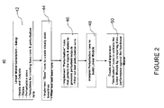
- FIG. 2 is a flow chart illustrating a process 40 for generating Linearized Engine Models (LEMs), according to one embodiment of the present invention. It is to be noted that this process in general applies to generating linear models numerically for any nonlinear model of a any physical system.
- the linear model or LEM structure is set up as represented in block 42, i.e. the inputs to be pertubed, their min and max values, the outputs of the LEMs (including their min/max values) and the states.
- one choice for the inputs includes the input actuators, health parameters and at times an input to the model that is not controlled.
- the outputs include all the control outputs that need to be fed back to the engine controller, all the constraint outputs that need to be fed back to the engine constraint controller if present and any other model outputs that are sensed or calculated and needed for control or estimation.
- the states of the model include speed states. Other important states of the model can be included as necessary. For example, for an aircraft engine, heat soak and clearance states can be included if they are fast enough to impact the dynamic performance of the engine controller
- the next step of the process 40 is represented in block 44 and creates a steady state base run which is referred to herein as the baseline for calculating deviations from perturbation run outputs.
- This step 44 involves three sub-steps, specifically if the nonlinear model of the aircraft engine has a solver - 1) getting a baseline, 2) tightening the solver tolerances and getting the baseline again, and 3) modifying the solver to run to the input values obtained in the previous step and getting the baseline again. This baseline is then used to calculate derivatives.
- Generating the perturbations is the next step as represented in block 46.
- the states and inputs are perturbed (i.e. 6 perturbations according to one embodiment) and the outputs of the model are recorded.
- the process of interpreting the perturbation run outputs as represented in block 48 involves the calculation of derivatives by dividing the deviation of perturbation run outputs from the baseline by the perturbation magnitude in the inputs and the states of the LEM.
- the LEM is then stored as a structure that contains the [A, B, C, D] matrices, the envelope conditions it was generated at (for example altitude, engine speed, ambient conditions,), the input base values, the output base values, and the list of input and output variables.
- the final step 50 is that of validating the generated LEMS against the offline nonlinear model. This is done by creating verification runs to run the offline nonlinear model through certain input perturbations. At the same time, the same input perturbations are passed to the generated LEM. The output response of the offline nonlinear model and the LEM are then compared. Certain metrics based upon the particular application are then used to judge the goodness and thereby the acceptability of the LEMs.
Landscapes
- Physics & Mathematics (AREA)
- General Physics & Mathematics (AREA)
- Engineering & Computer Science (AREA)
- Automation & Control Theory (AREA)
- Feedback Control In General (AREA)
Applications Claiming Priority (1)
| Application Number | Priority Date | Filing Date | Title |
|---|---|---|---|
| US12/473,413 US9618919B2 (en) | 2009-05-28 | 2009-05-28 | Real-time scheduling of linear models for control and estimation |
Publications (1)
| Publication Number | Publication Date |
|---|---|
| EP2256641A2 true EP2256641A2 (de) | 2010-12-01 |
Family
ID=42731817
Family Applications (1)
| Application Number | Title | Priority Date | Filing Date |
|---|---|---|---|
| EP10156974A Withdrawn EP2256641A2 (de) | 2009-05-28 | 2010-03-18 | Echtzeit-Planung von linearen Modellen zur Steuerung und Schätzung |
Country Status (4)
| Country | Link |
|---|---|
| US (1) | US9618919B2 (de) |
| EP (1) | EP2256641A2 (de) |
| JP (1) | JP2010277577A (de) |
| CA (1) | CA2697760A1 (de) |
Cited By (1)
| Publication number | Priority date | Publication date | Assignee | Title |
|---|---|---|---|---|
| EP3451085A1 (de) * | 2017-08-28 | 2019-03-06 | United Technologies Corporation | Verfahren zur auswahl optimaler motorbetriebsbedingungen zur erzeugung linearisierter modelle für bordsteuerung und schätzung |
Families Citing this family (11)
| Publication number | Priority date | Publication date | Assignee | Title |
|---|---|---|---|---|
| US8380473B2 (en) * | 2009-06-13 | 2013-02-19 | Eric T. Falangas | Method of modeling dynamic characteristics of a flight vehicle |
| JP5696629B2 (ja) * | 2011-09-20 | 2015-04-08 | トヨタ自動車株式会社 | 内燃機関の制御入力値演算方法 |
| JP6359471B2 (ja) * | 2015-02-13 | 2018-07-18 | トヨタテクニカルディベロップメント株式会社 | シミュレーション装置が参照するマップの生成装置及び生成方法 |
| JP6554905B2 (ja) | 2015-05-19 | 2019-08-07 | 株式会社リコー | 情報処理装置、情報処理方法およびプログラム |
| US10296402B2 (en) | 2015-12-17 | 2019-05-21 | Entit Software Llc | Scheduling jobs |
| US12056425B2 (en) | 2017-06-02 | 2024-08-06 | The Mathworks, Inc. | Systems and methods for rescaling executable simulation models |
| US11454188B2 (en) * | 2017-06-02 | 2022-09-27 | The Mathworks, Inc. | Systems and methods for rescaling executable simulation models |
| US11200512B2 (en) | 2018-02-21 | 2021-12-14 | International Business Machines Corporation | Runtime estimation for machine learning tasks |
| CN110045751B (zh) * | 2019-05-14 | 2022-10-04 | 哈尔滨工程大学 | 基于si控制的有缆水下机器人海底定点着陆运动控制方法 |
| CN111456856B (zh) * | 2020-04-04 | 2023-03-24 | 西北工业大学 | 航空发动机最大推力状态降保守性鲁棒控制器 |
| CN120948933B (zh) * | 2025-08-25 | 2026-03-03 | 国网吉林省电力有限公司长春供电公司 | 一种智能配电自动化终端自动测试方法及系统 |
Family Cites Families (4)
| Publication number | Priority date | Publication date | Assignee | Title |
|---|---|---|---|---|
| US5094213A (en) * | 1991-02-12 | 1992-03-10 | General Motors Corporation | Method for predicting R-step ahead engine state measurements |
| US7472100B2 (en) * | 2006-09-29 | 2008-12-30 | United Technologies Corporation | Empirical tuning of an on board real-time gas turbine engine model |
| GB0712980D0 (en) * | 2007-07-04 | 2007-08-15 | Rolls Royce Plc | Engine performance model |
| US7885717B2 (en) * | 2008-03-31 | 2011-02-08 | Sikorsky Aircraft Corporation | Fast control law optimization |
-
2009
- 2009-05-28 US US12/473,413 patent/US9618919B2/en active Active
-
2010
- 2010-03-18 EP EP10156974A patent/EP2256641A2/de not_active Withdrawn
- 2010-03-24 JP JP2010067102A patent/JP2010277577A/ja active Pending
- 2010-03-25 CA CA2697760A patent/CA2697760A1/en not_active Abandoned
Non-Patent Citations (1)
| Title |
|---|
| None |
Cited By (2)
| Publication number | Priority date | Publication date | Assignee | Title |
|---|---|---|---|---|
| EP3451085A1 (de) * | 2017-08-28 | 2019-03-06 | United Technologies Corporation | Verfahren zur auswahl optimaler motorbetriebsbedingungen zur erzeugung linearisierter modelle für bordsteuerung und schätzung |
| US10378455B2 (en) | 2017-08-28 | 2019-08-13 | United Technologies Corporation | Method for selection of optimal engine operating conditions for generating linearized models for on-board control and estimation |
Also Published As
| Publication number | Publication date |
|---|---|
| US9618919B2 (en) | 2017-04-11 |
| US20100305912A1 (en) | 2010-12-02 |
| JP2010277577A (ja) | 2010-12-09 |
| CA2697760A1 (en) | 2010-11-28 |
Similar Documents
| Publication | Publication Date | Title |
|---|---|---|
| US9618919B2 (en) | Real-time scheduling of linear models for control and estimation | |
| Volponi et al. | The use of Kalman filter and neural network methodologies in gas turbine performance diagnostics: a comparative study | |
| US8577481B2 (en) | System and method for utilizing a hybrid model | |
| CN103649858B (zh) | 用于预测组件或系统状况的方法和设备 | |
| KR20160021209A (ko) | 동적 모델 식별을 모니터링 및 가변 구조 또는 가변 동작 조건을 가진 동적 기기의 제어 방법 및 시스템 | |
| JP6404909B2 (ja) | 技術的な系の出力量のモデルを算出する方法 | |
| Simon et al. | Sensor selection for aircraft engine performance estimation and gas path fault diagnostics | |
| Kobayashi et al. | Hybrid kalman filter approach for aircraft engine in-flight diagnostics: Sensor fault detection case | |
| Gao et al. | Novel parameter identification by using a high-gain observer with application to a gas turbine engine | |
| Dewallef et al. | A methodology to improve the robustness of gas turbine engine performance monitoring against sensor faults | |
| Grauer et al. | Method for real-time frequency response and uncertainty estimation | |
| Blesa et al. | Set‐membership parity space approach for fault detection in linear uncertain dynamic systems | |
| CN105676692A (zh) | 发电机组励磁智能控制系统 | |
| WO2016133578A2 (en) | Estimating dynamic thrust or shaft power of an engine | |
| US10429811B2 (en) | Systems and methods for testing convergence of closed-loop control systems | |
| Rausch et al. | Integrated in-flight fault detection and accommodation: A model-based study | |
| Sun et al. | Bayesian network-based multiple sources information fusion mechanism for gas path analysis | |
| Borguet et al. | A sensor-fault-tolerant diagnosis tool based on a quadratic programming approach | |
| CN118332237A (zh) | 信息处理装置、信息处理方法以及存储介质 | |
| Meseguer et al. | Approximating fault detection linear interval observers using λ‐order interval predictors | |
| Salim et al. | An ℋ∞ approach to data-driven simultaneous fault detection and control | |
| Wang et al. | Virtual fault derivative based iterative UIO design and convergent fault estimation for Lipschitz nonlinear systems: H.-J. Wang and S.-J. Huang | |
| Candon et al. | Stall Flutter of the Benchmark Supercritical Wing Using Aeroelastic Model Reduction and Tunable Turbulence Parameters | |
| Rausch et al. | Integrated in-flight fault detection and accommodation: a model-based study | |
| EP3168578A1 (de) | System zur schätzung der parameter aus sensormessungen |
Legal Events
| Date | Code | Title | Description |
|---|---|---|---|
| PUAI | Public reference made under article 153(3) epc to a published international application that has entered the european phase |
Free format text: ORIGINAL CODE: 0009012 |
|
| AK | Designated contracting states |
Kind code of ref document: A2 Designated state(s): AT BE BG CH CY CZ DE DK EE ES FI FR GB GR HR HU IE IS IT LI LT LU LV MC MK MT NL NO PL PT RO SE SI SK SM TR |
|
| AX | Request for extension of the european patent |
Extension state: AL BA ME RS |
|
| STAA | Information on the status of an ep patent application or granted ep patent |
Free format text: STATUS: THE APPLICATION IS DEEMED TO BE WITHDRAWN |
|
| 18D | Application deemed to be withdrawn |
Effective date: 20151001 |