EP2256013B1 - Système d'entraînement hybride pour véhicules ferroviaires - Google Patents
Système d'entraînement hybride pour véhicules ferroviaires Download PDFInfo
- Publication number
- EP2256013B1 EP2256013B1 EP10160183.9A EP10160183A EP2256013B1 EP 2256013 B1 EP2256013 B1 EP 2256013B1 EP 10160183 A EP10160183 A EP 10160183A EP 2256013 B1 EP2256013 B1 EP 2256013B1
- Authority
- EP
- European Patent Office
- Prior art keywords
- drive system
- energy
- combustion engine
- drive
- machine
- Prior art date
- Legal status (The legal status is an assumption and is not a legal conclusion. Google has not performed a legal analysis and makes no representation as to the accuracy of the status listed.)
- Not-in-force
Links
Images

Classifications
-
- B—PERFORMING OPERATIONS; TRANSPORTING
- B61—RAILWAYS
- B61C—LOCOMOTIVES; MOTOR RAILCARS
- B61C7/00—Other locomotives or motor railcars characterised by the type of motive power plant used; Locomotives or motor railcars with two or more different kinds or types of motive power
- B61C7/04—Locomotives or motor railcars with two or more different kinds or types of engines, e.g. steam and IC engines
-
- B—PERFORMING OPERATIONS; TRANSPORTING
- B61—RAILWAYS
- B61C—LOCOMOTIVES; MOTOR RAILCARS
- B61C7/00—Other locomotives or motor railcars characterised by the type of motive power plant used; Locomotives or motor railcars with two or more different kinds or types of motive power
- B61C7/02—Locomotives or motor railcars with pneumatic accumulators
-
- Y—GENERAL TAGGING OF NEW TECHNOLOGICAL DEVELOPMENTS; GENERAL TAGGING OF CROSS-SECTIONAL TECHNOLOGIES SPANNING OVER SEVERAL SECTIONS OF THE IPC; TECHNICAL SUBJECTS COVERED BY FORMER USPC CROSS-REFERENCE ART COLLECTIONS [XRACs] AND DIGESTS
- Y02—TECHNOLOGIES OR APPLICATIONS FOR MITIGATION OR ADAPTATION AGAINST CLIMATE CHANGE
- Y02T—CLIMATE CHANGE MITIGATION TECHNOLOGIES RELATED TO TRANSPORTATION
- Y02T30/00—Transportation of goods or passengers via railways, e.g. energy recovery or reducing air resistance
Definitions
- the invention relates to a drive system with a dynamoelectric machine, an internal combustion engine, an electrical energy storage and a pressure accumulator, wherein the dynamoelectric machine can be driven by the internal combustion engine to charge the electrical energy storage.
- One or more drive motors can then be supplied with electrical energy via the energy store in order, for example, to drive a rail vehicle.
- Such hybrid drive systems are used, for example, in diesel-electric rail vehicles.
- the same drive concept is also known for road vehicles such as cars and buses.
- the energy storage is designed as a DC link capacitor
- the input side is connected via a usually three-phase coupled to the dynamoelectric machine rectifier and is coupled via a usually also three-phase inverter with the drive motors of the corresponding vehicle.
- Such a generic system is based on the idea to create an electrically powered vehicle that derives its energy from fossil fuels and thus is not bound to an electrification of the route.
- the invention has for its object to provide a cost-effective hybrid drive system with the possibility of recuperative braking.
- the invention is based on the finding that a hybrid drive system can be improved in a particularly efficient manner for the recovery of brake energy by the integration of the comparatively simple, lightweight and cost-effective pressure accumulator.
- the dynamoelectric machine is this with both the electrical energy storage as well coupled with the accumulator, so that the energy flow to drive the machine can be done via both memories. If the dynamoelectric machine is driven by means of the energy stored in the electrical energy store, it works as a motor. So it converts electrical energy into mechanical energy that can be used to compress a medium arranged in the pressure accumulator. This happens, for example, when braking a vehicle, which is equipped with the drive system according to the invention. In such a case, the drive motors of the vehicle would generate regenerative electrical energy, which is initially stored in the electrical energy storage. This electrical energy is used to drive the dynamoelectric machine, which in turn compresses the medium in the accumulator.
- the electrical energy store may in particular be an intermediate circuit capacitor of an inverter. This serves primarily to smooth the DC link voltage and is permanently fed by the drive motors in the electric drive of the dynamoelectric machine described above. Thus, the energy for driving the dynamoelectric machine flows from the drive motors via the DC link capacitor, which acts here as an electrical energy store in the sense of claim 1, to the dynamoelectric machine.
- the stored in this way in the accumulator energy is in turn available for example for an acceleration process. It can therefore be used to drive the dynamoelectric machine so that it works as a generator and charges the electrical energy storage.
- the dynamo-electric machine is powered by the internal combustion engine, which derives its energy from a fossil fuel.
- the pressure accumulator in acceleration phases can by the pressure accumulator according to the invention, the fuel consumption be extremely minimized.
- the pressure accumulator is able to provide the energy required for accelerating almost instantaneously. Peak power, as required in an acceleration process, no longer need to be provided by the internal combustion engine alone, but can be at least partially supplied by the stored energy in the accumulator.
- the internal combustion engine can be driven by the stored energy in the pressure accumulator.
- the internal combustion engine is first accelerated with the stored energy in the pressure accumulator, which then drives the dynamoelectric machine via a drive shaft.
- An embodiment of the invention which is particularly advantageous in terms of efficiency, is characterized in that the internal combustion engine is designed as a diesel engine. Diesel engines have a higher efficiency compared to gasoline engines. Furthermore, the energy density of diesel fuel is relatively high, so that high ranges can be achieved with a diesel-electric powered vehicle.
- the drive system comprises a fluid energy machine coupled to the internal combustion engine via a drive shaft, wherein the fluid energy machine is designed to convert the energy stored in the pressure accumulator into mechanical energy for driving the internal combustion engine.
- the fluid energy machine which is in particular a pump / motor unit, is driven during a braking operation in front of the internal combustion engine, so that a medium located in the pressure accumulator is compressed.
- the energy thus obtained can be utilized in an acceleration process by operating the fluid energy machine as a motor and assisting the internal combustion engine. It is advantageous here if the fluid energy machine can be driven via the drive shaft for compressing a medium stored in the pressure accumulator via the internal combustion engine.
- the fluid energy machine is connected via the drive shaft with the internal combustion engine, which in turn is coupled via a further drive shaft with the dynamoelectric machine.
- the dynamo-electric machine drives the internal combustion engine via the additional drive shaft, which in turn acts via the drive shaft on the fluid energy machine, which compresses the medium in the accumulator as a pump.
- a particularly compact design is achieved in an embodiment of the invention, in which the fluid energy machine is flanged to the internal combustion engine.
- the internal combustion engine is configured as a compressor for compressing and relaxing a stored in the pressure accumulator medium.
- the function of the fluid energy machine described above is taken directly from the internal combustion engine with.
- relaxing the medium of the internal combustion engine is operated by the medium as an additional or even alternative energy source for fuel.
- a further advantageous embodiment of the drive system according to the invention is characterized in that it comprises a first converter, via which the dynamoelectric machine is connected to the electrical energy store, at least one drive motor and a second converter, via which the at least one drive motor is connected to the electrical energy store, having.
- both inverters must allow bidirectional energy flow.
- the first inverter is designed as a pulse inverter with turn-off semiconductor devices.
- the electrical energy storage is designed as a DC link capacitor.
- the drive system can be operated with common and well-proven voltage source converters.
- the DC link capacitor is used primarily for smoothing the DC link voltage.
- the switching triplets caused by the power semiconductors are greatly reduced by a sufficiently large selected capacitance of the DC link capacitor.
- the electrical energy store as a DC reactor and to configure the power converter accordingly as a DC link converter with corresponding semiconductor components.
- a separate dynamoelectrically acting starter for the internal combustion engine can be saved in an advantageous embodiment of the invention in that means for starting the internal combustion engine are present in the drive system by the stored energy in the pressure accumulator.
- the proposed drive system is suitable for a variety of vehicles.
- rail vehicles such as diesel-electric locomotives can be operated very efficiently with a drive system according to one of the previously described embodiments.
- FIG. 1 shows a known from the prior art diesel-electric drive system.
- This drive system comprises an internal combustion engine 2 designed as a diesel engine, which is connected via a shaft to a dynamoelectric machine 1 operated as a generator.
- the intermediate circuit voltage is converted into a three-phase alternating voltage, which is applied to the terminals of drive motors 8, with which the diesel-electric vehicle is finally driven.
- the dynamoelectric machine always works as a generator.
- a recuperative braking is made possible by an additional energy storage, which is connected in parallel with the DC link capacitor.
- These are so-called SuperCaps 10, which are coupled via a DC-DC converter 11 to the DC link capacitor.
- the drive motors 8 work as a generator so that they charge the intermediate circuit capacitor and the SuperCaps 10 via the second converter 9.
- the electrical energy stored in the SuperCaps 10 can now be made available in addition to the energy provided by the diesel generator and the dynamoelectric machine 1.
- the electrical energy storage 3 or the energy stored in the SuperCaps 10 does not only drive the vehicle used but in addition to the supply of auxiliary drives.
- a third converter 12 converts the DC voltage into a three-phase AC voltage for supplying additional components in the drive system.
- the illustrated drive system further comprises a braking resistor 13, in which excess energy can be "destroyed” in a conventional manner.
- a gate turn-of-thyristor (GTO) 14 is ignited, so that the intermediate circuit capacitor can be discharged via the braking resistor to the extent that the intermediate circuit voltage is below a permissible threshold value.
- the storage of the recuperatively provided energy in the SuperCaps 10 is comparatively expensive.
- Supercapacitors are still not cost-effective to get.
- a considerable construction volume for the supercapacitors is required in order to be able to completely buffer the recuperative energy generated when braking a diesel-electric locomotive.
- FIG. 2 shows a drive system according to an embodiment of the invention. Principally identical elements are provided here with the same reference numerals as in FIG. 1 , The main difference to the drive system according to FIG. 1 is the design and the coupling of the additional energy storage for receiving the braking energy.
- the internal combustion engine 2 is not only connected via a shaft to the dynamoelectric machine 1, but also via a drive shaft with a fluid energy machine 6, which is coupled to a pressure accumulator 4. With the help of this fluid energy machine, which is performed as a pump / motor unit, the medium in the pressure accumulator 4 can be compressed. This happens in which the pump / motor unit pumps the medium from a low-pressure tank 15 into the pressure accumulator 4.
- the pump / motor unit performs this operation during recuperative braking.
- the drive of the motors 8 during of the braking process provided and rectified by the second inverter 9 electrical voltage from the first inverter 7 in turn applied as a three-phase AC voltage to the terminals of the dynamoelectric machine 1.
- the expensive and heavy additional electrical energy storage with SuperCaps 10 off FIG. 1 can be omitted here.
- the first inverter 7 is designed as a pulse inverter with active semiconductor components such as IGBTs or GTOs, so that it allows a bidirectional flow of energy.
- the dynamoelectric machine 1 operates in this operating case as a motor and drives the engine 2 at. This in turn acts via the drive shaft 5 to the pump / motor unit with which the medium is pumped from the low-pressure tank 15 into the pressure accumulator 4.
- the pressure accumulator 4 returns its energy via the pump / motor unit, so that the fluid energy machine 6 drives the internal combustion engine 2 via the drive shaft 5.
- This energy is finally transmitted from the engine 2 to the dynamoelectric machine 1, which resumes according to the regenerative operation to provide electrical energy to drive the drive motors 8.
- the combustion engine also draws its energy from a fossil fuel.
- the accumulator 4 shown here and its coupling with the aid of the fluid energy machine 6 with the internal combustion engine 2 represents a much more efficient and cost-effective implementation of a hybrid drive system with which braking energy can be regenerated.
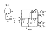
- FIG. 3 shows a further drive system according to another embodiment of the invention.
- This embodiment differs from that in FIG. 2 illustrated embodiment in that no own fluid energy machine 6 as a compressor is provided for compressing and relaxing the existing pressure in the accumulator 4 medium. Rather, this task is taken over by the internal combustion engine 2 with.
- pressure lines 16 are led directly from the accumulator 4 and from the low-pressure tank 15 to one or two cylinders of the internal combustion engine 2. It eliminates the additional pump / motor unit, so that the hardware cost for the entire system can be reduced.
Landscapes
- Engineering & Computer Science (AREA)
- Transportation (AREA)
- Mechanical Engineering (AREA)
- Electric Propulsion And Braking For Vehicles (AREA)
- Control Of Vehicle Engines Or Engines For Specific Uses (AREA)
Claims (11)
- Système d'entraînement comprenant- une machine ( 1 ) dynamoélectrique,- un moteur ( 2 ) à combustion interne pour l'entraînement de la machine ( 1 ) dynamoélectrique,- un accumulateur ( 3 ) d'énergie électrique pour l'accumulation d'une énergie électrique cédé par la machine dynamoélectrique dans un fonctionnement en génératrice, et- un accumulateur ( 4 ) de pression,caractérisé en ce que le système d'entraînement est conformé de manière à ce que la machine ( 1 ) dynamoélectrique puisse être entraînée tant par l'énergie accumulée dans l'accumulateur ( 3 ) d'énergie électrique qu'également par une énergie accumulée dans l'accumulateur ( 4 ) de pression.
- Système d'entraînement suivant la revendication 1,
dans lequel le moteur ( 2 ) à combustion interne peut être entraîné par l'énergie accumulée dans l'accumulateur ( 4 ) de pression. - Système d'entraînement suivant la revendication 1 ou 2,
dans lequel le moteur ( 2 ) à combustion interne est réalisé sous la forme d'un moteur diesel. - Système d'entraînement suivant l'une des revendications précédentes, comprenant une machine ( 6 ) à énergie fluidique couplée au moteur ( 2 ) à combustion interne par un arbre ( 5 ) d'entraînement, la machine ( 6 ) à énergie fluidique étant constituée pour transformer l'énergie accumulée dans l'accumulateur ( 4 ) de pression en énergie mécanique pour l'entraînement du moteur ( 2 ) à combustion interne.
- Système d'entraînement suivant la revendication 4,
dans lequel la machine ( 6 ) à énergie fluidique peut être entraînée par l'arbre ( 5 ) d'entraînement pour la compression par le moteur ( 2 ) à combustion interne d'un milieu accumulé dans l'accumulateur ( 4 ) de pression. - Système d'entraînement suivant la revendication 4 ou 5,
dans lequel la machine ( 6 ) à énergie fluidique est bridée sur le moteur ( 2 ) à combustion interne. - Système d'entraînement suivant l'une des revendications 1 à 3,
dans lequel le moteur ( 2 ) à combustion interne est agencé en compresseur pour la compression et la détente d'un milieu accumulé dans l'accumulateur ( 4 ) de pression. - Système d'entraînement suivant l'une des revendications précédentes,
dans lequel le système d'entraînement a- un premier convertisseur ( 7 ) par lequel, la machine ( 1 ) dynamoélectrique est reliée à l'accumulateur ( 3 ) d'énergie électrique,- au moins un moteur ( 8 ) d'entraînement et- un deuxième convertisseur ( 9 ) par lequel le au moins un moteur ( 8 ) d'entraînement est relié à l'accumulateur ( 3 ) d'énergie électrique. - Système d'entraînement suivant l'une des revendications précédentes,
dans lequel l'accumulateur ( 3 ) d'énergie électrique est réalisé sous la forme d'un condensateur de circuit intermédiaire. - Système d'entraînement suivant l'une des revendications précédentes, comprenant des moyens pour faire démarrer le moteur ( 2 ) à combustion interne par l'énergie accumulée dans l'accumulateur ( 4 ) de pression.
- Véhicule ferroviaire ayant un système d'entraînement suivant l'une des revendications précédentes.
Applications Claiming Priority (1)
| Application Number | Priority Date | Filing Date | Title |
|---|---|---|---|
| DE102009023101A DE102009023101A1 (de) | 2009-05-28 | 2009-05-28 | Hybrides Antriebssystem für Schienenfahrzeuge |
Publications (3)
| Publication Number | Publication Date |
|---|---|
| EP2256013A2 EP2256013A2 (fr) | 2010-12-01 |
| EP2256013A3 EP2256013A3 (fr) | 2012-06-06 |
| EP2256013B1 true EP2256013B1 (fr) | 2014-08-27 |
Family
ID=42670325
Family Applications (1)
| Application Number | Title | Priority Date | Filing Date |
|---|---|---|---|
| EP10160183.9A Not-in-force EP2256013B1 (fr) | 2009-05-28 | 2010-04-16 | Système d'entraînement hybride pour véhicules ferroviaires |
Country Status (3)
| Country | Link |
|---|---|
| EP (1) | EP2256013B1 (fr) |
| DE (1) | DE102009023101A1 (fr) |
| ES (1) | ES2502942T3 (fr) |
Families Citing this family (4)
| Publication number | Priority date | Publication date | Assignee | Title |
|---|---|---|---|---|
| JP6169403B2 (ja) * | 2013-04-26 | 2017-07-26 | 株式会社日立製作所 | 鉄道車両用駆動システム及びこれを搭載した鉄道車両 |
| DE102013008420A1 (de) * | 2013-05-17 | 2014-11-20 | Abb Technology Ag | Antriebseinheit zur Ansteuerung eines Motors |
| EP3223420B1 (fr) * | 2016-03-22 | 2020-05-06 | Siemens Aktiengesellschaft | Système de convertisseur de courant destiné au freinage fiable d'un système d'entrainement |
| EP3778285A1 (fr) * | 2019-08-16 | 2021-02-17 | Siemens Aktiengesellschaft | Système d'entraînement d'un véhicule électrique-diesel |
Family Cites Families (3)
| Publication number | Priority date | Publication date | Assignee | Title |
|---|---|---|---|---|
| DE393869C (de) * | 1921-01-22 | 1924-04-08 | Vaporackumulator Ab | Verbrennungsmotorlokomotive |
| DE102006011167A1 (de) * | 2006-03-10 | 2007-09-13 | Linde Material Handling Gmbh & Co. Kg | Hydrostatisch-elektrischer Antrieb |
| US20080083576A1 (en) * | 2006-10-04 | 2008-04-10 | Read David H | Regenerative energy storage system for hybrid locomotive |
-
2009
- 2009-05-28 DE DE102009023101A patent/DE102009023101A1/de not_active Withdrawn
-
2010
- 2010-04-16 EP EP10160183.9A patent/EP2256013B1/fr not_active Not-in-force
- 2010-04-16 ES ES10160183.9T patent/ES2502942T3/es active Active
Also Published As
| Publication number | Publication date |
|---|---|
| EP2256013A2 (fr) | 2010-12-01 |
| ES2502942T3 (es) | 2014-10-06 |
| EP2256013A3 (fr) | 2012-06-06 |
| DE102009023101A1 (de) | 2010-12-02 |
Similar Documents
| Publication | Publication Date | Title |
|---|---|---|
| DE102012011914B4 (de) | Motoransteuervorrichtung, die mit einer Energiespeichereinheit ausgestattet ist | |
| EP2387524B1 (fr) | Réseau de bord et transformateur de tension pour un véhicule et procédé pour commander un réseau de bord à tension multiple | |
| EP2996898B1 (fr) | Unité d'entraînement pour la commande d'un moteur | |
| DE10231379B3 (de) | Antriebssystem für ein Kraftfahrzeug mit einem Verbrennungsmotor und einer elektrischen Maschine | |
| DE102010017417A1 (de) | Elektrisches Versorgungs- und Startsystem für ein Kraftfahrzeug und Verfahren zum Betrieb des elektrischen Versorgungs- und Startsystems | |
| DE102006042945B4 (de) | Verfahren zur Effizienzsteigerung von dieselelektrisch getriebenen Fahrzeugen und Fahrzeug zur Durchführung des Verfahrens | |
| DE102010028972A1 (de) | Motorantriebssystem für ein Hybridfahrzeug und Verfahren zum Steuern desselben | |
| WO2011103987A2 (fr) | Système d'entraînement et machine de travail | |
| EP2941363B1 (fr) | Alimentation en énergie électrique de moteurs électriques de propulsion d'un véhicule ferroviaire à l'aide d'une pluralité de moteurs à combustion | |
| EP2433830A1 (fr) | Procédé de commande pour la préparation d'énergie électrique à partir d'une machine synchrone triphasée entraînée | |
| EP2256013B1 (fr) | Système d'entraînement hybride pour véhicules ferroviaires | |
| EP1403130A2 (fr) | Véhicule de travail | |
| WO2015172924A1 (fr) | Dispositif et procédé pour charger deux accumulateurs d'énergie | |
| DE102012007158A1 (de) | Pulswechselrichter mit Stromzwischenkreis zum Fahren und Laden eines batteriebetriebenen Elektrofahrzeugs | |
| WO2020260112A1 (fr) | Véhicule présentant une pièce de véhicule électroconductrice pouvant être utilisée comme élément de résistance pour convertir de l'énergie électrique en chaleur | |
| DE3525107A1 (de) | Antriebs- und betriebsbremsanlage von kraftfahrzeugen | |
| DE102011110639A1 (de) | Energieversorgungssteuerungseinrichtung | |
| DE102010025266A1 (de) | Transportfahrzeug mit einer Mehrzahl elektrischer Maschinen | |
| WO2021032557A1 (fr) | Système d'entraînement d'un véhicule diesel-électrique | |
| EP1412218B1 (fr) | Systeme moteur hybride et procede de regulation de ce systeme moteur hybride | |
| EP3184349A1 (fr) | Systeme d'alimentation en energie d'un vehicule et vehicule comprenant un systeme de traction electrique | |
| WO2012159830A1 (fr) | Véhicule hybride et procédé permettant de faire fonctionner un véhicule hybride | |
| DE102010063795B4 (de) | Kettengetriebenes Pistenfahrzeug mit seriellem Hybridantrieb | |
| WO2010105869A1 (fr) | Véhicule électrique pourvu d'un appareil chargeur de batterie | |
| DE102008064565A1 (de) | Transportfahrzeug mit einer Mehrzahl elektrischer Maschinen |
Legal Events
| Date | Code | Title | Description |
|---|---|---|---|
| PUAI | Public reference made under article 153(3) epc to a published international application that has entered the european phase |
Free format text: ORIGINAL CODE: 0009012 |
|
| AK | Designated contracting states |
Kind code of ref document: A2 Designated state(s): AT BE BG CH CY CZ DE DK EE ES FI FR GB GR HR HU IE IS IT LI LT LU LV MC MK MT NL NO PL PT RO SE SI SK SM TR |
|
| AX | Request for extension of the european patent |
Extension state: AL BA ME RS |
|
| PUAL | Search report despatched |
Free format text: ORIGINAL CODE: 0009013 |
|
| AK | Designated contracting states |
Kind code of ref document: A3 Designated state(s): AT BE BG CH CY CZ DE DK EE ES FI FR GB GR HR HU IE IS IT LI LT LU LV MC MK MT NL NO PL PT RO SE SI SK SM TR |
|
| AX | Request for extension of the european patent |
Extension state: AL BA ME RS |
|
| RIC1 | Information provided on ipc code assigned before grant |
Ipc: B61C 7/04 20060101ALI20120427BHEP Ipc: B61C 7/02 20060101AFI20120427BHEP |
|
| 17P | Request for examination filed |
Effective date: 20120518 |
|
| RAP1 | Party data changed (applicant data changed or rights of an application transferred) |
Owner name: SIEMENS AKTIENGESELLSCHAFT |
|
| GRAP | Despatch of communication of intention to grant a patent |
Free format text: ORIGINAL CODE: EPIDOSNIGR1 |
|
| INTG | Intention to grant announced |
Effective date: 20140328 |
|
| GRAS | Grant fee paid |
Free format text: ORIGINAL CODE: EPIDOSNIGR3 |
|
| GRAA | (expected) grant |
Free format text: ORIGINAL CODE: 0009210 |
|
| AK | Designated contracting states |
Kind code of ref document: B1 Designated state(s): AT BE BG CH CY CZ DE DK EE ES FI FR GB GR HR HU IE IS IT LI LT LU LV MC MK MT NL NO PL PT RO SE SI SK SM TR |
|
| REG | Reference to a national code |
Ref country code: GB Ref legal event code: FG4D Free format text: NOT ENGLISH |
|
| REG | Reference to a national code |
Ref country code: CH Ref legal event code: EP |
|
| REG | Reference to a national code |
Ref country code: AT Ref legal event code: REF Ref document number: 684371 Country of ref document: AT Kind code of ref document: T Effective date: 20140915 |
|
| REG | Reference to a national code |
Ref country code: IE Ref legal event code: FG4D Free format text: LANGUAGE OF EP DOCUMENT: GERMAN |
|
| REG | Reference to a national code |
Ref country code: ES Ref legal event code: FG2A Ref document number: 2502942 Country of ref document: ES Kind code of ref document: T3 Effective date: 20141006 |
|
| REG | Reference to a national code |
Ref country code: DE Ref legal event code: R096 Ref document number: 502010007746 Country of ref document: DE Effective date: 20141009 |
|
| REG | Reference to a national code |
Ref country code: LT Ref legal event code: MG4D |
|
| REG | Reference to a national code |
Ref country code: NL Ref legal event code: VDEP Effective date: 20140827 |
|
| PG25 | Lapsed in a contracting state [announced via postgrant information from national office to epo] |
Ref country code: NO Free format text: LAPSE BECAUSE OF FAILURE TO SUBMIT A TRANSLATION OF THE DESCRIPTION OR TO PAY THE FEE WITHIN THE PRESCRIBED TIME-LIMIT Effective date: 20141127 Ref country code: PT Free format text: LAPSE BECAUSE OF FAILURE TO SUBMIT A TRANSLATION OF THE DESCRIPTION OR TO PAY THE FEE WITHIN THE PRESCRIBED TIME-LIMIT Effective date: 20141229 Ref country code: SE Free format text: LAPSE BECAUSE OF FAILURE TO SUBMIT A TRANSLATION OF THE DESCRIPTION OR TO PAY THE FEE WITHIN THE PRESCRIBED TIME-LIMIT Effective date: 20140827 Ref country code: FI Free format text: LAPSE BECAUSE OF FAILURE TO SUBMIT A TRANSLATION OF THE DESCRIPTION OR TO PAY THE FEE WITHIN THE PRESCRIBED TIME-LIMIT Effective date: 20140827 Ref country code: GR Free format text: LAPSE BECAUSE OF FAILURE TO SUBMIT A TRANSLATION OF THE DESCRIPTION OR TO PAY THE FEE WITHIN THE PRESCRIBED TIME-LIMIT Effective date: 20141128 Ref country code: BG Free format text: LAPSE BECAUSE OF FAILURE TO SUBMIT A TRANSLATION OF THE DESCRIPTION OR TO PAY THE FEE WITHIN THE PRESCRIBED TIME-LIMIT Effective date: 20141127 Ref country code: LT Free format text: LAPSE BECAUSE OF FAILURE TO SUBMIT A TRANSLATION OF THE DESCRIPTION OR TO PAY THE FEE WITHIN THE PRESCRIBED TIME-LIMIT Effective date: 20140827 |
|
| PG25 | Lapsed in a contracting state [announced via postgrant information from national office to epo] |
Ref country code: CY Free format text: LAPSE BECAUSE OF FAILURE TO SUBMIT A TRANSLATION OF THE DESCRIPTION OR TO PAY THE FEE WITHIN THE PRESCRIBED TIME-LIMIT Effective date: 20140827 Ref country code: LV Free format text: LAPSE BECAUSE OF FAILURE TO SUBMIT A TRANSLATION OF THE DESCRIPTION OR TO PAY THE FEE WITHIN THE PRESCRIBED TIME-LIMIT Effective date: 20140827 Ref country code: IS Free format text: LAPSE BECAUSE OF FAILURE TO SUBMIT A TRANSLATION OF THE DESCRIPTION OR TO PAY THE FEE WITHIN THE PRESCRIBED TIME-LIMIT Effective date: 20141227 Ref country code: HR Free format text: LAPSE BECAUSE OF FAILURE TO SUBMIT A TRANSLATION OF THE DESCRIPTION OR TO PAY THE FEE WITHIN THE PRESCRIBED TIME-LIMIT Effective date: 20140827 |
|
| PG25 | Lapsed in a contracting state [announced via postgrant information from national office to epo] |
Ref country code: NL Free format text: LAPSE BECAUSE OF FAILURE TO SUBMIT A TRANSLATION OF THE DESCRIPTION OR TO PAY THE FEE WITHIN THE PRESCRIBED TIME-LIMIT Effective date: 20140827 |
|
| PG25 | Lapsed in a contracting state [announced via postgrant information from national office to epo] |
Ref country code: DK Free format text: LAPSE BECAUSE OF FAILURE TO SUBMIT A TRANSLATION OF THE DESCRIPTION OR TO PAY THE FEE WITHIN THE PRESCRIBED TIME-LIMIT Effective date: 20140827 Ref country code: RO Free format text: LAPSE BECAUSE OF FAILURE TO SUBMIT A TRANSLATION OF THE DESCRIPTION OR TO PAY THE FEE WITHIN THE PRESCRIBED TIME-LIMIT Effective date: 20140827 Ref country code: SK Free format text: LAPSE BECAUSE OF FAILURE TO SUBMIT A TRANSLATION OF THE DESCRIPTION OR TO PAY THE FEE WITHIN THE PRESCRIBED TIME-LIMIT Effective date: 20140827 Ref country code: EE Free format text: LAPSE BECAUSE OF FAILURE TO SUBMIT A TRANSLATION OF THE DESCRIPTION OR TO PAY THE FEE WITHIN THE PRESCRIBED TIME-LIMIT Effective date: 20140827 Ref country code: CZ Free format text: LAPSE BECAUSE OF FAILURE TO SUBMIT A TRANSLATION OF THE DESCRIPTION OR TO PAY THE FEE WITHIN THE PRESCRIBED TIME-LIMIT Effective date: 20140827 |
|
| REG | Reference to a national code |
Ref country code: DE Ref legal event code: R097 Ref document number: 502010007746 Country of ref document: DE |
|
| PG25 | Lapsed in a contracting state [announced via postgrant information from national office to epo] |
Ref country code: PL Free format text: LAPSE BECAUSE OF FAILURE TO SUBMIT A TRANSLATION OF THE DESCRIPTION OR TO PAY THE FEE WITHIN THE PRESCRIBED TIME-LIMIT Effective date: 20140827 |
|
| PLBE | No opposition filed within time limit |
Free format text: ORIGINAL CODE: 0009261 |
|
| STAA | Information on the status of an ep patent application or granted ep patent |
Free format text: STATUS: NO OPPOSITION FILED WITHIN TIME LIMIT |
|
| 26N | No opposition filed |
Effective date: 20150528 |
|
| PG25 | Lapsed in a contracting state [announced via postgrant information from national office to epo] |
Ref country code: SI Free format text: LAPSE BECAUSE OF FAILURE TO SUBMIT A TRANSLATION OF THE DESCRIPTION OR TO PAY THE FEE WITHIN THE PRESCRIBED TIME-LIMIT Effective date: 20140827 Ref country code: LU Free format text: LAPSE BECAUSE OF FAILURE TO SUBMIT A TRANSLATION OF THE DESCRIPTION OR TO PAY THE FEE WITHIN THE PRESCRIBED TIME-LIMIT Effective date: 20150416 Ref country code: MC Free format text: LAPSE BECAUSE OF FAILURE TO SUBMIT A TRANSLATION OF THE DESCRIPTION OR TO PAY THE FEE WITHIN THE PRESCRIBED TIME-LIMIT Effective date: 20140827 |
|
| REG | Reference to a national code |
Ref country code: CH Ref legal event code: PL |
|
| REG | Reference to a national code |
Ref country code: IE Ref legal event code: MM4A |
|
| PG25 | Lapsed in a contracting state [announced via postgrant information from national office to epo] |
Ref country code: LI Free format text: LAPSE BECAUSE OF NON-PAYMENT OF DUE FEES Effective date: 20150430 Ref country code: CH Free format text: LAPSE BECAUSE OF NON-PAYMENT OF DUE FEES Effective date: 20150430 |
|
| PG25 | Lapsed in a contracting state [announced via postgrant information from national office to epo] |
Ref country code: IE Free format text: LAPSE BECAUSE OF NON-PAYMENT OF DUE FEES Effective date: 20150416 |
|
| REG | Reference to a national code |
Ref country code: FR Ref legal event code: PLFP Year of fee payment: 7 |
|
| REG | Reference to a national code |
Ref country code: AT Ref legal event code: MM01 Ref document number: 684371 Country of ref document: AT Kind code of ref document: T Effective date: 20150416 |
|
| PG25 | Lapsed in a contracting state [announced via postgrant information from national office to epo] |
Ref country code: AT Free format text: LAPSE BECAUSE OF NON-PAYMENT OF DUE FEES Effective date: 20150416 |
|
| PG25 | Lapsed in a contracting state [announced via postgrant information from national office to epo] |
Ref country code: MT Free format text: LAPSE BECAUSE OF FAILURE TO SUBMIT A TRANSLATION OF THE DESCRIPTION OR TO PAY THE FEE WITHIN THE PRESCRIBED TIME-LIMIT Effective date: 20140827 |
|
| REG | Reference to a national code |
Ref country code: FR Ref legal event code: PLFP Year of fee payment: 8 |
|
| PG25 | Lapsed in a contracting state [announced via postgrant information from national office to epo] |
Ref country code: HU Free format text: LAPSE BECAUSE OF FAILURE TO SUBMIT A TRANSLATION OF THE DESCRIPTION OR TO PAY THE FEE WITHIN THE PRESCRIBED TIME-LIMIT; INVALID AB INITIO Effective date: 20100416 Ref country code: SM Free format text: LAPSE BECAUSE OF FAILURE TO SUBMIT A TRANSLATION OF THE DESCRIPTION OR TO PAY THE FEE WITHIN THE PRESCRIBED TIME-LIMIT Effective date: 20140827 |
|
| PG25 | Lapsed in a contracting state [announced via postgrant information from national office to epo] |
Ref country code: BE Free format text: LAPSE BECAUSE OF NON-PAYMENT OF DUE FEES Effective date: 20150430 |
|
| PG25 | Lapsed in a contracting state [announced via postgrant information from national office to epo] |
Ref country code: TR Free format text: LAPSE BECAUSE OF FAILURE TO SUBMIT A TRANSLATION OF THE DESCRIPTION OR TO PAY THE FEE WITHIN THE PRESCRIBED TIME-LIMIT Effective date: 20140827 |
|
| REG | Reference to a national code |
Ref country code: FR Ref legal event code: PLFP Year of fee payment: 9 |
|
| PG25 | Lapsed in a contracting state [announced via postgrant information from national office to epo] |
Ref country code: MK Free format text: LAPSE BECAUSE OF FAILURE TO SUBMIT A TRANSLATION OF THE DESCRIPTION OR TO PAY THE FEE WITHIN THE PRESCRIBED TIME-LIMIT Effective date: 20140827 |
|
| PGFP | Annual fee paid to national office [announced via postgrant information from national office to epo] |
Ref country code: DE Payment date: 20180619 Year of fee payment: 9 |
|
| PGFP | Annual fee paid to national office [announced via postgrant information from national office to epo] |
Ref country code: IT Payment date: 20180423 Year of fee payment: 9 Ref country code: FR Payment date: 20180412 Year of fee payment: 9 |
|
| PGFP | Annual fee paid to national office [announced via postgrant information from national office to epo] |
Ref country code: ES Payment date: 20180724 Year of fee payment: 9 Ref country code: GB Payment date: 20180410 Year of fee payment: 9 |
|
| REG | Reference to a national code |
Ref country code: DE Ref legal event code: R081 Ref document number: 502010007746 Country of ref document: DE Owner name: SIEMENS MOBILITY GMBH, DE Free format text: FORMER OWNER: SIEMENS AKTIENGESELLSCHAFT, 80333 MUENCHEN, DE |
|
| REG | Reference to a national code |
Ref country code: GB Ref legal event code: 732E Free format text: REGISTERED BETWEEN 20190207 AND 20190213 |
|
| REG | Reference to a national code |
Ref country code: DE Ref legal event code: R119 Ref document number: 502010007746 Country of ref document: DE |
|
| GBPC | Gb: european patent ceased through non-payment of renewal fee |
Effective date: 20190416 |
|
| PG25 | Lapsed in a contracting state [announced via postgrant information from national office to epo] |
Ref country code: GB Free format text: LAPSE BECAUSE OF NON-PAYMENT OF DUE FEES Effective date: 20190416 Ref country code: DE Free format text: LAPSE BECAUSE OF NON-PAYMENT OF DUE FEES Effective date: 20191101 |
|
| PG25 | Lapsed in a contracting state [announced via postgrant information from national office to epo] |
Ref country code: FR Free format text: LAPSE BECAUSE OF NON-PAYMENT OF DUE FEES Effective date: 20190430 |
|
| PG25 | Lapsed in a contracting state [announced via postgrant information from national office to epo] |
Ref country code: IT Free format text: LAPSE BECAUSE OF NON-PAYMENT OF DUE FEES Effective date: 20190416 |
|
| REG | Reference to a national code |
Ref country code: ES Ref legal event code: FD2A Effective date: 20200831 |
|
| PG25 | Lapsed in a contracting state [announced via postgrant information from national office to epo] |
Ref country code: ES Free format text: LAPSE BECAUSE OF NON-PAYMENT OF DUE FEES Effective date: 20190417 |